JP3973929B2 - Howling detection device - Google Patents
Howling detection device Download PDFInfo
- Publication number
- JP3973929B2 JP3973929B2 JP2002058891A JP2002058891A JP3973929B2 JP 3973929 B2 JP3973929 B2 JP 3973929B2 JP 2002058891 A JP2002058891 A JP 2002058891A JP 2002058891 A JP2002058891 A JP 2002058891A JP 3973929 B2 JP3973929 B2 JP 3973929B2
- Authority
- JP
- Japan
- Prior art keywords
- power
- unit
- processing unit
- output
- signals
- Prior art date
- Legal status (The legal status is an assumption and is not a legal conclusion. Google has not performed a legal analysis and makes no representation as to the accuracy of the status listed.)
- Expired - Lifetime
Links
Images


Classifications
-
- H—ELECTRICITY
- H04—ELECTRIC COMMUNICATION TECHNIQUE
- H04R—LOUDSPEAKERS, MICROPHONES, GRAMOPHONE PICK-UPS OR LIKE ACOUSTIC ELECTROMECHANICAL TRANSDUCERS; DEAF-AID SETS; PUBLIC ADDRESS SYSTEMS
- H04R3/00—Circuits for transducers, loudspeakers or microphones
- H04R3/02—Circuits for transducers, loudspeakers or microphones for preventing acoustic reaction, i.e. acoustic oscillatory feedback
Landscapes
- Health & Medical Sciences (AREA)
- General Health & Medical Sciences (AREA)
- Otolaryngology (AREA)
- Physics & Mathematics (AREA)
- Engineering & Computer Science (AREA)
- Acoustics & Sound (AREA)
- Signal Processing (AREA)
- Circuit For Audible Band Transducer (AREA)
- Fittings On The Vehicle Exterior For Carrying Loads, And Devices For Holding Or Mounting Articles (AREA)
- Golf Clubs (AREA)
- Diaphragms For Electromechanical Transducers (AREA)
Abstract
Description
【0001】
【発明の属する技術分野】
本発明は、マイクロホンとスピーカを有する音響装置において、スピーカとマイクロホン間の音響結合により発生するハウリングを自動的に検出するハウリング検出装置に関する。
【0002】
【従来の技術】
従来、マイクロホンとスピーカを組み合わせた音響装置では、スピーカで再生された音がマイクロホンに回り込むことによりフィードバックループが形成され、ハウリングが発生することがある。
【0003】
このハウリングを検出する装置として、AES東京コンベンション’95予稿集、p112〜115「DSPを使ったハウリング検出・除去の自動システム」柘植他、に記載されたものが知られている。
【0004】
図12は、従来のハウリング検出装置の構成例を示すブロック図であり、このハウリング検出装置は、マイクロホン等に接続される信号入力端子1001と、信号入力端子1001に入力された時間信号を複数の周波数帯域に分割する帯域分割処理部1002と、帯域分割処理部1002で複数の周波数帯域に分割された時間信号の絶対値を算出する振幅算出部1003と、ハウリングが発生しているか否かの判定を行うハウリング判定部1004と、ハウリング検出結果を出力する信号出力端子1005とを備えている。
【0005】
このようなハウリング検出装置において、信号入力端子1001に入力された時間信号は、帯域分割処理部1002で複数の周波数帯域に分割される。振幅算出部1003では、各帯域の信号の絶対値を算出する。この処理は、時々刻々変化する入力信号の周波数特性の測定に相当する。ハウリング判定部1004では、振幅算出部1003から出力された絶対値の全周波数帯域に対する最大値を常時監視し、最大値が予め設定された閾値を超え、かつピークを示す周波数値が複数回連続した場合にハウリング発生と判定し、判定結果を信号出力端子1005に出力する。
【0006】
このようにして周波数軸上でピークを示すハウリングの特徴に着目することにより、ハウリングの検出を自動的に行っていた。
【0007】
【発明が解決しようとする課題】
しかし、このような従来のハウリング検出装置では、各周波数帯域信号の絶対値の最大値を参照してハウリングの検出を行っているため、ハウリング検出処理が入力信号のレベルに大きく依存してしまい、レベルの大きな信号が継続して入力された場合や暗騒音レベルが非常に大きな場合にはハウリングの誤検出を引き起こす可能性があるという問題があった。
【0008】
本発明はこのような問題を解決するためになされたもので、精度良く安定してハウリングを検出することができるハウリング検出装置を提供するものである。
【0009】
【課題を解決するための手段】
本発明のハウリング検出装置は、時間信号を複数の周波数信号に分割する周波数分割処理部と、前記複数の周波数信号を遅延させる遅延器と、前記遅延器から出力される複数の遅延信号に係数を乗じる適応フィルタと、前記複数の周波数信号と前記複数の遅延信号と前記適応フィルタから出力される複数のフィルタ出力信号とに基づいて、前記適応フィルタの係数を更新する係数更新処理部と、前記複数のフィルタ出力信号それぞれのパワーを算出する周波数パワー算出部と、前記周波数パワー算出部が算出したパワーに対して平滑化を行う平滑化処理部と、前記平滑化処理部から出力される前記複数のフィルタ出力信号それぞれのパワーが時間的に増大しているか否かの判定を行うパワー増大判定処理部と、前記周波数分割処理部が出力する複数の周波数信号それぞれのパワーを算出する第2の周波数パワー算出部と、前記第2の周波数パワー算出部が算出したパワーに対して平滑化を行う第2の平滑化処理部と、前記第2の平滑化処理部から出力される前記複数の周波数信号それぞれのパワーが時間的に増大しているか否かの判定を行う第2のパワー増大判定処理部と、前記平滑化処理部から出力される前記複数のフィルタ出力信号それぞれのパワーが、他の前記フィルタ出力信号のパワーと比較して突出しているか否かの判定を行うパワー比判定処理部と、前記パワー増大判定処理部と前記第2のパワー増大判定処理部と前記パワー比判定処理部の出力結果に基づきハウリング発生か否かの判定を行うハウリング判定部とを備えた構成を有している。
【0010】
この構成により、入力信号が複数の周波数信号に分割され、それぞれの信号について適応フィルタによりハウリング成分である単一正弦波状信号が抽出され、パワー比判定処理部は、抽出されたそれぞれの信号のハウリング成分のパワーが他の信号のパワーに比べて突出していないかを判定し、パワー増大判定処理部及び第2のパワー増大判定処理部は、抽出されたそれぞれの信号のハウリング成分のパワーが時間的に増大しているかを判定し、ハウリング判定部は、パワー増大判定処理部と第2のパワー増大判定処理部とパワー比判定処理部の出力結果に基づきハウリング発生か否かの判定を行うので、入力信号のレベルのみに依存せず、レベルの大きな信号が継続して入力された場合や暗騒音レベルが非常に大きな場合においても、従来と比較してハウリング発生時に精度の高い安定したハウリング検出を行うことができるとともに、狭帯域成分の強い信号とハウリングの選別精度を向上させ、ハウリングの誤検出を低減することができる。
【0013】
また、前記周波数分割処理部が出力する複数の周波数信号に係数を乗じ、前記係数を乗じた複数の周波数信号を前記第2の周波数パワー算出部に出力する予測フィルタを備えることは好ましい。
【0014】
この構成により、複数の周波数信号に分割された入力信号は係数を乗じられ、それぞれの信号のパワーが時間的に増大しているかの判定も用いてハウリングが検出されることとなる。
【0015】
また、前記周波数パワー算出部及び前記第2の周波数パワー算出部は、入力される複数の信号それぞれに対してバンド化を行い、前記バンド化を行った複数の信号それぞれのパワーを算出することは好ましい。
【0016】
この構成により、分割された信号はバンド化され、パワーが算出されることとなる。
【0017】
本発明のハウリング検出装置は、時間信号を予め設定された周波数帯域毎の複数の時間信号に分割する帯域分割処理部と、前記複数の時間信号を遅延させる遅延器と、前記遅延器から出力される複数の遅延信号に係数を畳み込む適応フィルタと、前記複数の時間信号と前記複数の遅延信号と前記適応フィルタから出力される複数のフィルタ出力信号とに基づいて、前記適応フィルタの係数を更新する係数更新処理部と、前記複数のフィルタ出力信号それぞれのパワーを算出する帯域パワー算出部と、前記帯域パワー算出部が算出したパワーに対して平滑化を行う平滑化処理部と、前記平滑化処理部から出力される前記複数のフィルタ出力信号それぞれのパワーが時間的に増大しているか否かの判定を行うパワー増大判定処理部と、前記帯域分割処理部が出力する複数の時間信号それぞれのパワーを算出する第2の帯域パワー算出部と、前記第2の帯域パワー算出部が算出したパワーに対して平滑化を行う第2の平滑化処理部と、前記第2の平滑化処理部から出力される前記複数の時間信号それぞれのパワーが時間的に増大しているか否かの判定を行う第2のパワー増大判定処理部と、前記平滑化処理部から出力される前記複数のフィルタ出力信号それぞれのパワーが、他の前記フィルタ出力信号のパワーと比較して突出しているか否かの判定を行うパワー比判定処理部と、前記パワー増大判定処理部と前記第2のパワー増大判定処理部と前記パワー比判定処理部の出力結果に基づきハウリング発生か否かの判定を行うハウリング判定部とを備えた構成を有している。
【0018】
この構成により、入力信号が複数の時間信号に分割され、それぞれの信号について適応フィルタによりハウリング成分である単一正弦波状信号が抽出され、パワー比判定処理部は、抽出されたそれぞれの信号のハウリング成分のパワーが他の信号のパワーに比べて突出していないかを判定し、パワー増大判定処理部及び第2のパワー増大判定処理部は、抽出されたそれぞれの信号のハウリング成分のパワーが時間的に増大しているかを判定し、ハウリング判定部は、パワー増大判定処理部と第2のパワー増大判定処理部とパワー比判定処理部の出力結果に基づきハウリング発生か否かの判定を行うので、入力信号のレベルのみに依存せず、レベルの大きな信号が継続して入力された場合や暗騒音レベルが非常に大きな場合においても、従来と比較してハウリング発生時に精度の高い安定したハウリング検出を行うことができるとともに、狭帯域成分の強い信号とハウリングの選別精度を向上させ、ハウリングの誤検出を低減することができる。
【0021】
また、前記帯域分割処理部が出力する複数の時間信号と係数を畳み込み、前記係数を畳み込んだ複数の時間信号を前記第2の帯域パワー算出部に出力する予測フィルタを備えることは好ましい。
【0022】
この構成により、複数の時間信号に分割された入力信号は係数を畳み込まれ、それぞれの信号のパワーが時間的に増大しているかの判定も用いてハウリングが検出されることとなる。
【0023】
また、前記パワー増大判定処理部及び前記第2のパワー増大判定処理部は、入力された複数の信号のパワーを遅延させるパワー遅延器と、入力されたパワーと前記パワー遅延器から出力されるパワーとを前記複数の信号毎に比較するパワー比較部と、前記パワー比較部の比較結果に基づいて、前記パワー遅延器出力より前記平滑化処理部出力が大きい場合の処理フレーム数をカウントするパワー増大判定カウンタ部とを備えたことは好ましい。
【0024】
この構成により、分割された入力信号それぞれについて、パワーが時間的に増大しているか否かが判定され、パワーが時間的に増大しているフレーム数がカウントされることとなる。
【0025】
また、前記パワー増大判定処理部及び前記第2のパワー増大判定処理部は、入力された複数の信号の複数の処理フレームの間におけるパワーの最大値を算出する最大値算出部と、前記複数の信号のパワー最大値を遅延させるパワー最大値遅延器と、前記最大値算出部から出力されるパワー最大値と前記パワー最大値遅延器から出力されるパワー最大値とを前記複数の信号毎に比較するパワー比較部と、前記パワー比較部の比較結果に基づいて、前記パワー最大値遅延器から出力されるパワー最大値より前記最大値算出部から出力されるパワー最大値が大きい場合の処理フレーム数をカウントするパワー増大判定カウンタ部とを備えたことは好ましい。
【0026】
この構成により、分割された入力信号それぞれについて、複数の処理フレームの間のパワーの最大値が増大しているか否かが判定され、パワーの最大値が増大しているフレーム数がカウントされることとなる。
【0027】
また、前記パワー増大判定処理部及び前記第2のパワー増大判定処理部は、入力された複数の信号の複数の処理フレームの間におけるパワーの最小値を算出する最小値算出部と、前記複数の信号のパワー最小値を遅延させるパワー最小値遅延器と、前記最小値算出部から出力されるパワー最小値と前記パワー最小値遅延器から出力されるパワー最小値とを前記複数の信号毎に比較するパワー比較部と、前記パワー比較部の比較結果に基づいて、前記パワー最小値遅延器から出力されるパワー最小値より前記最小値算出部から出力されるパワー最小値が大きい場合の処理フレーム数をカウントするパワー増大判定カウンタ部とを備えたことは好ましい。
【0028】
この構成により、分割された入力信号それぞれについて、複数の処理フレームの間のパワーの最小値が増大しているか否かが判定され、パワーの最小値が増大しているフレーム数がカウントされることとなる。
【0031】
また、前記パワー増大判定処理部、前記第2のパワー増大判定処理部、及び前記パワー比判定処理部は、前記入力される複数の信号の一部の信号に対してのみ判定処理を行うことは好ましい。
【0032】
この構成により、分割された入力信号の一部の信号に対してのみパワー増大判定及びパワー比判定が行われることとなる。
【0033】
【発明の実施の形態】
以下、本発明の実施の形態について、図面を参照して説明する。
【0034】
(第1の実施の形態)(参考例)
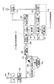
図1は本発明の第1の実施の形態のハウリング検出装置を示すブロック図である。
【0035】
図1に示すように、本実施の形態のハウリング検出装置は、図示していないマイクロホン等から信号が入力される信号入力端子101と、信号入力端子101に入力された信号をアナログ信号からディジタル信号へ変換するA/Dコンバータ102と、A/Dコンバータ102から出力される時間信号を変換して複数の周波数信号に分割する周波数分割処理部103と、周波数分割処理部103から出力される各周波数信号を遅延させて後述する適応フィルタ105の参照信号を生成する遅延器104と、遅延器104から出力される参照信号に常時更新される係数を乗じる適応フィルタ105と、周波数分割処理部103から出力される周波数信号と遅延器104から出力される信号と適応フィルタ105から出力される信号とに基づいて適応フィルタ105の係数更新を行う係数更新処理部106と、周波数分割処理部103から出力される信号と適応フィルタ105から出力される信号の差分をとる加算器107と、適応フィルタ105から出力される複数の周波数信号それぞれのパワーを算出する周波数パワー算出部108と、周波数パワー算出部108により算出された各周波数信号のパワーの平滑化を行う平滑化処理部109と、平滑化処理部109から出力される分割された各信号のパワーが時間的に増大しているか否かの判定を行うパワー増大判定処理部110と、特定の信号のパワーが他の信号のパワーと比較して突出しているか否かの判定を行うパワー比判定処理部111と、パワー増大判定処理部110及びパワー比判定処理部111の判定結果に基づきハウリング発生か否かの判定を行うハウリング判定部112と、ハウリング判定部112における判定結果を出力する信号出力端子113とを備えている。
【0036】
また、パワー増大判定処理部110は、平滑化処理部109によって平滑化された分割された信号毎のパワー値を遅延させる遅延器121と、平滑化処理部109から出力されるパワー値と遅延器121から出力されるパワー値との比較をそれぞれの信号毎に行うパワー比較部122と、パワー比較部122の比較結果に基づいて、遅延器121から出力されるパワー値より平滑化処理部109から出力されるパワー値が大きい場合の処理フレーム数をカウントし、そのカウンタ値を出力するパワー増大判定カウンタ部123とを備えている。
【0037】
また、パワー比判定処理部111は、平滑化処理部109によって平滑化された分割された信号のパワーの平均値(以下、パワー平均値という。)を算出する平均パワー算出部131と、平滑化処理部109によって平滑化を行われた分割された信号それぞれのパワー値と平均パワー算出部131によって算出されたパワー平均値との倍率差であるパワー比を算出するパワー比算出部132と、パワー比算出部132によって算出された分割された信号それぞれのパワー比と予め定めた第1のハウリング検出用閾値との比較を行うパワー比比較部133と、パワー比比較部133の比較結果に基づいて、パワー比が第1のハウリング検出用閾値を超えた処理フレーム数をカウントし、そのカウンタ値を出力するパワー比判定カウンタ部134とを備えている。
【0038】
このようなハウリング検出装置において、図示していないマイクロホン等から信号入力端子101へ入力された時間信号は、A/Dコンバータ102によりアナログ信号からディジタル信号に変換された後、周波数分割処理部103に入力され、予め設定された周波数間隔の複数の周波数信号へ変換される。ここで、周波数分割処理部103で行う複数の周波数信号への分割方法としては、高速フーリエ変換などの時間−周波数変換を用いる。
【0039】
周波数分割処理部103から出力される信号を希望信号とし、適応フィルタ105へは希望信号を遅延器104により遅延させた信号を参照信号として入力させる。ここで、遅延器104における遅延フレーム数としては、希望信号と参照信号に含まれている信号成分が互いに相関を持たなくなるような値に設定する。
【0040】
希望信号に対して十分に長い遅延を与えた場合、遅延器104の入力信号と出力信号の相関は十分小さくなり、ほぼ無相関とみなすことができるが、単一正弦波状信号に酷似したハウリング成分は依然として十分強い相関を有する。このため、遅延器104から出力される信号を適応フィルタ105のハウリング成分の参照信号として用いる。
【0041】
適応フィルタ105では、参照信号とフィルタ係数を乗じ、係数更新処理部106では、参照信号と、適応フィルタ105の出力信号と希望信号の差分信号を出力する加算器107の出力(誤差信号)から、二乗平均誤差が最小となるよう、適応フィルタ105の係数の更新を常時行う(図中、適応フィルタ105からの斜めの太線矢印は、適応フィルタ105の係数が更新されることを示している)。
【0042】
これは、二乗平均誤差を最小とすると、希望信号と参照信号で相関のある信号、すなわちハウリング成分が適応フィルタ105から出力され、入力信号からハウリング成分を抽出できるためである。
【0043】
なお、適応フィルタ105の係数更新アルゴリズムとしては、よく知られている複素LMS(Least Mean Square)アルゴリズム、複素NLMS(Normalized Least Mean Square)アルゴリズム、複素RLS(Recursive Least Squares)アルゴリズム、複素FRLS(Fast Recursive Least Squares)アルゴリズム等を用いる。
【0044】
例えば、複素NLMSアルゴリズムを用いた場合、適応フィルタ105の入力信号(参照信号)をX(k)、希望信号と適応フィルタ105の出力信号との差分である誤差信号をE(k)、適応フィルタ105の係数をW(k)とすると、複素NLMSアルゴリズムの更新式は次の数1で表される。
【0045】
【数1】

ここで、kはフレーム数、αは係数更新の大きさを制御するステップサイズパラメータ、δは充分小さな定数、*は複素共役、Tは転置を表す。
【0047】
なお、ここでは例として複素NLMSアルゴリズムを示したが、他のアルゴリズムにおいても数1のような適応アルゴリズムにより、適応フィルタ105の係数は、係数更新処理部106により二乗平均誤差を最小とする規範で自動的に更新される。
【0048】
周波数パワー算出部108では、適応フィルタ105の出力を用いて各周波数毎のパワーを算出し、平滑化処理部109で平滑化を行う。ここで、現在の処理フレームkにおいて周波数パワー算出部108で算出された周波数のパワーをP_pre(k)とし、現在の処理フレームkにおける平滑化した周波数のパワーをP(k)とすると、平滑化処理部109による平滑化は、忘却係数FF(Forgetting Factor)を用いた次式で示される移動平均によって行われる。なお、忘却係数FFは、0<FF≪1の関係を満たす係数である。
P(k) = FF×P_pre(k)+(1.0-FF)×P(k-1)
【0049】
パワー増大判定処理部110の遅延器121では、平滑化処理部109で平滑化された分割された信号それぞれのパワー値を遅延させパワー比較部122に入力する。
【0050】
パワー比較部122では、平滑化処理部109から出力される分割された信号それぞれについて現在の処理フレームのパワー値と遅延器121から出力された過去の処理フレームのパワー値の比較を行い、ある信号の過去の処理フレームのパワー値より現在の処理フレームのパワー値が大きい場合、パワー増大判定カウンタ部123にカウンタをインクリメントさせる。
【0051】
パワー増大判定カウンタ部123は、インクリメントしたカウンタ値をハウリング判定部112に出力する。
【0052】
パワー比判定処理部111の平均パワー算出部131では、分割された信号のパワーの平均値を算出し、パワー比算出部132に入力する。
【0053】
パワー比算出部132では、各信号のパワー値とパワー平均値との倍率差であるパワー比を算出し、パワー比比較部133では、分割された信号それぞれについてパワー比と予め設定された第1のハウリング検出用閾値と比較を行い、ある信号におけるパワー比が第1のハウリング検出用閾値を超えた場合、パワー比判定カウンタ部134にカウンタをインクリメントさせる。
【0054】
パワー比判定カウンタ部134は、インクリメントしたカウンタ値をハウリング判定部112に出力する。
【0055】
ハウリング判定部112では、パワー増大判定カウンタ部123のカウンタ値が予め定めた第2のハウリング検出用閾値を超え、かつパワー比判定カウンタ部134のカウンタ値が予め定めた第3のハウリング検出用閾値を超えた場合、ハウリング発生と判定し、判定結果を信号出力端子113へ出力する。
【0056】
なお、パワー増大判定カウンタ部123においてカウンタをインクリメント中にパワー比較部122におけるハウリング判定条件を満たさなくなった場合、パワー比較部122は、パワー増大判定カウンタ部123にカウンタ値をリセットさせる。
【0057】
また、パワー比判定カウンタ部134においてカウンタをインクリメント中にパワー比比較部133におけるハウリング判定条件を満たさなくなった場合には、パワー比比較部133は、パワー比判定カウンタ部134にカウンタ値をリセットさせる。
【0058】
以上のように、本実施の形態においては、入力された信号に含まれるハウリング成分である単一正弦波状信号の抽出を適応フィルタ105によって適応的に行った後、適応フィルタ105から出力される信号をハウリングの発生を検出する際の参照信号として用い、パワー比判定処理部111において、他の周波数のパワーに比べてパワーが突出している周波数が存在するかの判定を行うことにより、入力信号のレベルのみに依存せず、レベルの大きな信号が継続して入力された場合や暗騒音レベルが非常に大きな場合においても、従来と比較してハウリング発生時に精度の高い安定したハウリング検出を行うことができる。
【0059】
また、パワー増大判定処理部110において、各周波数のパワーが時間的に増大しているか否かの判定を行い、狭帯域成分の強い信号とハウリングを選別することで、ハウリングの誤検出を低減することができる。
【0060】
本実施の形態の他の態様としては、図2に示すように、周波数パワー算出部108に代えて、適応フィルタ105から出力される分割されたそれぞれの周波数信号を所定のポイント数ずつ加算することでバンド化を行い、バンド化を行った信号のパワーを算出する周波数バンドパワー算出部141を用いる。このように構成することによって、より少ない演算量でハウリング検出を行うことができる。
【0061】
なお、本実施形態において、パワー増大判定処理部110における遅延器121、パワー比較部122、パワー増大判定カウンタ部123、またパワー比判定処理部111におけるパワー比算出部132、パワー比比較部133、パワー比判定カウンタ部134、及びハウリング判定部112の処理を一部の周波数(即ち、ハウリング発生が予想される周波数)の信号のみに限定して施すようにすれば、演算量を削減することができる。
【0062】
(第2の実施の形態)
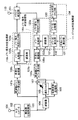
図3は本発明の第2の実施の形態のハウリング検出装置を示すブロック図である。なお、本実施の形態は、上述の第1の実施の形態と略同様に構成されているので、同様な構成には同一の符号を付して特徴部分のみ説明する。
【0063】
本実施の形態においては、周波数分割処理部103の出力信号のパワーを参照し、周波数分割処理部103の出力信号の周波数パワーが時間的に増大しているか否かをハウリング発生の判定に用いることを特徴としている。
【0064】
具体的には、本実施の形態のハウリング検出装置は、適応フィルタ105の希望信号である周波数分割処理部103の出力信号を入力される周波数パワー算出部108bと、周波数パワー算出部108bにより算出されたパワーに対し平滑化を行う平滑化処理部109bと、平滑化処理部109bから出力される信号のパワーが時間的に増大しているかを判定するパワー増大判定処理部110bと、パワー比判定処理部111とパワー増大判定処理部110a、110bの判定結果に基づきハウリング発生か否かの判定を行うハウリング判定部201とを備えている。
【0065】
パワー増大判定処理部110bの遅延器121bは、平滑化処理部109bによって平滑化されたパワー値を遅延させ、パワー比較部122bは、平滑化処理部109bから出力されるパワー値と遅延器121bから出力されるパワー値との比較を行い、遅延器121bから出力されるパワー値より平滑化処理部109bから出力されるパワー値が大きい場合、パワー増大判定カウンタ部123bにカウンタをインクリメントさせる。
【0066】
パワー増大判定カウンタ部123bは、インクリメントしたカウンタ値をハウリング判定部201に出力する。
【0067】
ハウリング判定部201は、パワー増大判定カウンタ部123aのカウンタ値が予め定めた第2のハウリング検出用閾値を超え、かつパワー比判定カウンタ部134のカウンタ値が予め定めた第3のハウリング検出用閾値を超え、かつパワー増大判定カウンタ部123bのカウンタ値が予め定めた第4のハウリング検出用閾値を超えた場合、ハウリング発生と判定し、判定結果を信号出力端子113へ出力する。
【0068】
なお、パワー増大判定カウンタ部123bにおいてカウンタをインクリメント中にパワー比較部122bにおけるハウリング判定条件を満たさなくなった場合、パワー比較部122bは、パワー増大判定カウンタ部123bにカウンタ値をリセットさせる。
【0069】
以上のように、本実施の形態においては、入力された信号に含まれるハウリング成分である単一正弦波状信号の抽出を適応フィルタ105によって適応的に行った後、適応フィルタ105から出力される信号をハウリングの発生を検出する際の参照信号として用い、パワー比判定処理部111において、他の周波数のパワーに比べてパワーが突出している周波数が存在するかの判定を行うことにより、入力信号のレベルのみに依存せず、レベルの大きな信号が継続して入力された場合や暗騒音レベルが非常に大きな場合においても、従来と比較してハウリング発生時に精度の高い安定したハウリング検出を行うことができる。
【0070】
また、適応フィルタ105の希望信号と出力信号の間で遅延差が生じることを利用し、適応フィルタ105の出力信号及び希望信号の各周波数のパワーが時間的に増大しているか否かの判定をパワー増大判定処理部110a、110bにおいてそれぞれ行うことにより、狭帯域成分の強い信号とハウリングの選別精度を向上させ、ハウリングの誤検出を低減することができる。
【0071】
本実施の形態の他の態様としては、図4に示すように、周波数パワー算出部108a、108bに代えて、入力される分割されたそれぞれの周波数信号を所定のポイント数ずつ加算することでバンド化を行い、バンド化を行った信号のパワーを算出する周波数バンドパワー算出部141a、141bを用いる。このように構成することによって、より少ない演算量でハウリング検出を行うことができる。
【0072】
(第3の実施の形態)
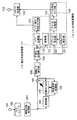
図5は本発明の第3の実施の形態のハウリング検出装置を示すブロック図である。なお、本実施の形態は、上述の第2の実施の形態と略同様に構成されているので、同様な構成には同一の符号を付して特徴部分のみ説明する。
【0073】
本実施の形態においては、周波数分割処理部103と周波数パワー算出部108bとの間に予測フィルタ301を設け、周波数分割処理部103の出力信号に係数を乗じることで予測信号を生成することを特徴としている。
【0074】
具体的には、適応フィルタ105は、係数更新処理部106で設定される係数を予測フィルタ301に転送する。予測フィルタ301は、適応フィルタ105から転送された係数を周波数分割処理部103の出力信号に乗じ、予測信号を生成する。この予測信号は、同時に単一正弦波状信号の抽出処理も施されることになる。
【0075】
予測フィルタ301から出力された予測信号は、周波数パワー算出部108bで各周波数毎のパワーを算出され、平滑化処理部109bで平滑化される。
【0076】
その後、パワー増大判定処理部110bでは平滑化処理部109bで平滑化された予測信号のパワー値が時間的に増大しているか否かの判定処理を行う。
【0077】
ハウリング判定部201は、パワー増大判定処理部110a、110b、パワー比判定処理部111の判定結果によりハウリング発生の検出を行う。
【0078】
以上のように、本実施の形態においては、入力された信号に含まれるハウリング成分である単一正弦波状信号の抽出を適応フィルタ105によって適応的に行った後、適応フィルタ105から出力される信号をハウリングの発生を検出する際の参照信号として用い、パワー比判定処理部111において、他の周波数のパワーに比べてパワーが突出している周波数が存在するかの判定を行うことにより、入力信号のレベルのみに依存せず、レベルの大きな信号が継続して入力された場合や暗騒音レベルが非常に大きな場合においても、従来と比較してハウリング発生時に精度の高い安定したハウリング検出を行うことができる。
【0079】
また、予測フィルタ301において、適応フィルタ105の係数を用いて現在の信号から未来の単一正弦波状信号抽出処理を施された予測信号を生成し、この予測信号の各周波数のパワーが時間的に増大しているか否かの判定を行うことにより、狭帯域成分の強い信号とハウリングの選別精度を向上させ、ハウリングの誤検出を低減することができる。
【0080】
本実施の形態の他の態様としては、図6に示すように、周波数パワー算出部108a、108bに代えて、入力される分割されたそれぞれの周波数信号を所定のポイント数ずつ加算することでバンド化を行い、バンド化を行った信号のパワーを算出する周波数バンドパワー算出部141a、141bを用いる。このように構成することによって、より少ない演算量でハウリング検出を行うことができる。
【0081】
(第4の実施の形態)(参考例)
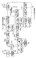
図7は本発明の第4の実施の形態のハウリング検出装置を示すブロック図である。なお、本実施の形態は、上述の第1の実施の形態と略同様に構成されているので、同様な構成には同一の符号を付して特徴部分のみ説明する。
【0082】
本実施の形態においては、入力信号を複数の帯域に分割し、分割した帯域毎のパワーによりハウリングの発生を検出することを特徴としている。
【0083】
具体的には、帯域分割処理部401は、入力された時間信号を複数のFIR(Finite Impulse Response)型バンドパスフィルタやIIR(Infinite Impulse Response)型バンドパスフィルタ、または演算量を削減可能なサブバンド信号処理を用いて予め設定された周波数帯域別に複数の時間信号に分割する。
【0084】
分割された信号は、遅延器104、適応フィルタ105を通って帯域パワー算出部402に入力される。
【0085】
帯域パワー算出部402では、各周波数帯域に分割された時間信号のパワーを算出してハウリング検出のための参照信号として平滑化処理部109へ出力する。
【0086】
平滑化処理部109で平滑化されたパワー値は、パワー増大判定処理部110、パワー比判定処理部により判定され、その判定結果によりハウリング判定部112によりハウリングが検出される。
【0087】
以上のように、本実施の形態においては、入力された信号に含まれるハウリング成分である単一正弦波状信号の抽出を適応フィルタ105によって適応的に行った後、適応フィルタ105から出力される信号をハウリングの発生を検出する際の参照信号として用い、パワー比判定処理部111において、帯域のパワーが他の帯域のパワーに比べて突出しているか否かの判定を行うことにより、入力信号のレベルのみに依存せず、レベルの大きな信号が継続して入力された場合や暗騒音レベルが非常に大きな場合においても、従来と比較してハウリング発生時に精度の高い安定したハウリング検出を行うことができる。
【0088】
また、パワー増大判定処理部110において、各帯域のパワーが時間的に増大しているか否かの判定を行い、狭帯域成分の強い信号とハウリングを選別することで、ハウリングの誤検出を低減させることができる。
【0089】
また、本実施の形態においては、時間信号を周波数信号に変換することなく、ハウリングの検出を行うことができる。
【0090】
なお、本実施の形態において、パワー増大判定処理部110における遅延器121、パワー比較部122、パワー増大判定カウンタ部123、またパワー比判定処理部111におけるパワー比算出部132、パワー比比較部133、パワー比判定カウンタ部134、及びハウリング判定部112の処理を一部の周波数帯域(即ち、ハウリング発生が予想される周波数帯域)の時間信号のみに限定して施すようにすれば、演算量を削減することができる。
【0091】
(第5の実施の形態)
図8は本発明の第5の実施の形態のハウリング検出装置を示すブロック図である。なお、本実施の形態は、上述の第2、第4の実施の形態と略同様に構成されているので、同様な構成には同一の符号を付して特徴部分のみ説明する。
【0092】
本実施の形態においては、帯域分割処理部401の出力信号のパワーを参照し、帯域分割処理部401の出力信号のパワーが時間的に増大しているか否かをハウリング発生の判定に用いることを特徴としている。
【0093】
具体的には、本実施の形態のハウリング検出装置は、適応フィルタ105の希望信号である帯域分割処理部401の出力信号を入力される帯域パワー算出部402bと、帯域パワー算出部402bにより算出されたパワーに対し平滑化を行う平滑化処理部109bと、平滑化処理部109bから出力される信号のパワーが時間的に増大しているかを判定するパワー増大判定処理部110bとを備えている。
【0094】
このようなハウリング検出装置において、適応フィルタ105の希望信号である帯域分割処理部401の出力信号は、帯域パワー算出部402bでパワーを算出される。
【0095】
この算出されたパワーは、平滑化処理部109bで平滑化された後、パワー増大判定処理部110bで時間的に増大しているか否かの判定が行われ、ハウリング判定部201は、パワー増大判定処理部110bの判定結果も用いてハウリングの発生を検出する。
【0096】
以上のように、本実施の形態においては、入力された信号に含まれるハウリング成分である単一正弦波状信号の抽出を適応フィルタ105によって適応的に行った後、適応フィルタ105から出力される信号をハウリングの発生を検出する際の参照信号として用い、パワー比判定処理部111において、帯域のパワーが他の帯域のパワーに比べて突出しているか否かの判定を行うことにより、入力信号のレベルのみに依存せず、レベルの大きな信号が継続して入力された場合や暗騒音レベルが非常に大きな場合においても、従来と比較してハウリング発生時に精度の高い安定したハウリング検出を行うことができる。
【0097】
また、適応フィルタの希望信号と出力信号の間で遅延差が生じることを利用し、適応フィルタの出力信号及び希望信号の各帯域のパワーが時間的に増大しているか否かの判定を、パワー増大判定処理部110a、110bにおいてそれぞれ行うことにより、狭帯域成分の強い信号とハウリングの選別精度を向上させ、ハウリングの誤検出を低減させることができる。
【0098】
(第6の実施の形態)
図9は本発明の第6の実施の形態のハウリング検出装置を示すブロック図である。なお、本実施の形態は、上述の第3、第5の実施の形態と略同様に構成されているので、同様な構成には同一の符号を付して特徴部分のみ説明する。
【0099】
本実施の形態においては、帯域分割処理部401と帯域パワー算出部402bとの間に予測フィルタ301を設け、周波数分割処理部103の出力信号と係数を畳み込むことで予測信号を生成することを特徴としている。
【0100】
具体的には、適応フィルタ105は、係数更新処理部106で設定される係数を予測フィルタ301に転送する。予測フィルタ301は、適応フィルタ105から転送された係数と帯域分割処理部401の出力信号を畳み込み、予測信号を生成する。
【0101】
予測フィルタ301から出力された予測信号は、帯域パワー算出部402bで各帯域毎のパワーを算出される。
【0102】
この算出されたパワーは、平滑化処理部109bで平滑化された後、パワー増大判定処理部110bで時間的に増大しているか否かの判定が行われ、ハウリング判定部201は、パワー増大判定処理部110bの判定結果も用いてハウリングの発生を検出する。
【0103】
以上のように、本実施の形態においては、入力された信号に含まれるハウリング成分である単一正弦波状信号の抽出を適応フィルタ105によって適応的に行った後、適応フィルタ105から出力される信号をハウリングの発生を検出する際の参照信号として用い、パワー比判定処理部111において、帯域のパワーが他の帯域のパワーに比べて突出しているか否かの判定を行うことにより、入力信号のレベルのみに依存せず、レベルの大きな信号が継続して入力された場合や暗騒音レベルが非常に大きな場合においても、従来と比較してハウリング発生時に精度の高い安定したハウリング検出を行うことができる。
【0104】
また、予測フィルタ301を用いて現在の信号から未来の単一正弦波状信号抽出処理を施された予測信号を生成し、この予測信号の帯域のパワーが時間的に増大しているか否かの判定をパワー増大判定処理部110bにおいて行うことにより、狭帯域成分の強い信号とハウリングの選別精度を向上させ、ハウリングの誤検出を低減することができる。
【0105】
(第7の実施の形態)
図10は本発明の第7の実施の形態のハウリング検出装置のパワー増大判定処理部を示すブロック図である。なお、本実施の形態は、上述の第1から第6の実施の形態のパワー増大判定処理部の別の構成例を示したものであり、同様な構成には同一の符号を付して特徴部分のみ説明する。
【0106】
本実施の形態においては、平滑化を行われた分割された信号それぞれのパワー値の複数の処理フレームの間における最大値(以下、パワー最大値という。)を算出する最大値算出部701を設け、複数の処理フレームの間の最大値が増大しているかを判定することを特徴としている。
【0107】
具体的には、最大値算出部701は、信号入力端子702に入力された分割された信号それぞれの平滑化されたパワー値を1フレームずつ遅延させ、現在の処理フレームから過去Nfフレーム前の処理フレームまでの各パワー値を保持しておき、現在の処理フレームからNfフレーム前までの間のそれぞれの信号のパワー最大値を算出する。
【0108】
その後は上述の実施の形態と同様に、最大値算出部701で算出されたパワー最大値と、遅延器121で遅延されたパワー最大値を比較し、遅延器121から出力されるパワー最大値より最大値算出部701から出力されるパワー最大値が大きい場合の処理フレーム数をカウントし、そのカウンタ値を信号出力端子703に出力する。
【0109】
以上のように、本実施の形態においては、複数の処理フレームの間におけるパワー最大値を算出し、パワー最大値が時間的に増大しているか否かの判定を行うことにより、パワー値の微少変動を低減することができ、狭帯域成分の強い信号とハウリングの選別精度を向上させ、ハウリングの誤検出を低減することが可能となる。
【0110】
なお、本実施の形態において、平滑化されたパワー値の微少変動を低減するために複数の処理フレームの間におけるパワー最大値を算出しているが、同様にして複数の処理フレームの間におけるパワー最小値を算出し、パワー最小値によりパワーが時間的に増大しているか否かを判定してもよい。
【0111】
(第8の実施の形態)
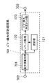
図11は、本発明の第8の実施の形態の音響装置を示すブロック図である。なお、本実施の形態のハウリング検出装置803は、上述の第1から第7の実施の形態のいずれかのハウリング検出装置を使うものである。
【0112】
本実施の形態の音響装置は、マイクロホン801と、マイクロホン801に入力される信号を増幅するマイクアンプ802と、マイクアンプ802から出力される信号に対してハウリングの検出処理を行うハウリング検出装置803と、ハウリング検出装置803のハウリング検出結果に基づいてハウリングの抑圧処理を行うハウリング抑圧装置804と、ハウリング抑圧装置804から出力される信号を増幅するパワーアンプ805と、パワーアンプ805から出力される信号に基づいて音を出力するスピーカ806とを備えている。
【0113】
このような音響装置において、マイクロホン801へ入力された時間信号は、マイクアンプ802により増幅された後にハウリング検出装置803及びハウリング抑圧装置804へそれぞれ入力される。ハウリング抑圧装置804から出力される信号は、パワーアンプ805により増幅された後にスピーカ806によって出力される。
【0114】
ここで、スピーカ806から1.0以上のゲインを有する音が再びマイクロホン801へ入力されてハウリングが発生した場合、ハウリング検出装置803ではハウリングの検出を行い、ハウリング抑圧装置804ではハウリングが検出された周波数又は周波数バンドまたは周波数帯域のゲインを、例えばノッチフィルタ又はバンドカットフィルタ又はパラメトリックイコライザを用いたり、或いは1.0以下の乗数を乗じることで低減することにより、ハウリングの抑圧を行う。
【0115】
以上のように、本実施の形態においては、ハウリング検出装置803によりハウリングを従来と比較して精度良く検出し、抑圧することができるので、聴感上耳障りであったものを改善することができるのに加え、ハウリングの発生によって制限されていたパワーアンプ805の利得を向上することができる。
【0116】
【発明の効果】
以上説明したように、本発明によれば、入力された信号を複数の周波数信号に分割し、それぞれの信号に含まれるハウリング成分である単一正弦波状信号の抽出を適応的に行った後、特定の周波数信号の抽出した単一正弦波状信号のパワーが他の周波数信号のパワーに比べて突出しているか否かの判定を行うことにより、入力信号のレベルのみに依存せず、レベルの大きな信号が継続して入力された場合や暗騒音レベルが非常に大きな場合においても、精度の高い安定したハウリング検出を行うことができる。
【0117】
また、各周波数信号のパワーが時間的に増大しているか否かの判定を行っているので、狭帯域成分の強い信号とハウリングを選別することで、ハウリングの誤検出を低減することができる。
【図面の簡単な説明】
【図1】本発明の第1の実施の形態のハウリング検出装置を示す概略ブロック図
【図2】本発明の第1の実施の形態の他の態様のハウリング検出装置を示す概略ブロック図
【図3】本発明の第2の実施の形態のハウリング検出装置を示す概略ブロック図
【図4】本発明の第2の実施の形態の他の態様のハウリング検出装置を示す概略ブロック図
【図5】本発明の第3の実施の形態のハウリング検出装置を示す概略ブロック図
【図6】本発明の第3の実施の形態の他の態様のハウリング検出装置を示す概略ブロック図
【図7】本発明の第4の実施の形態のハウリング検出装置を示す概略ブロック図
【図8】本発明の第5の実施の形態のハウリング検出装置を示す概略ブロック図
【図9】本発明の第6の実施の形態のハウリング検出装置を示す概略ブロック図
【図10】本発明の第7の実施の形態のハウリング検出装置を示す概略ブロック図
【図11】本発明の第8の実施の形態のハウリング検出装置を示す概略ブロック図
【図12】従来のハウリング検出装置を示す概略ブロック図
【符号の説明】
101 信号入力端子
102 A/Dコンバータ
103 周波数分割処理部
104 遅延器
105 適応フィルタ
106 係数更新処理部
107 加算器
108、108a、108b 周波数パワー算出部
109、109a、109b 平滑化処理部
110、110a、110b パワー増大判定処理部
111、111a、111b パワー比判定処理部
112 ハウリング判定部
113 信号出力端子
121、121a、121b 遅延器
122、122a、122b パワー比較部
123、123a、123b パワー増大判定カウンタ部
131 平均パワー算出部
132 パワー比算出部
133 パワー比比較部
134 パワー比判定カウンタ部
141、141a、141b 周波数バンドパワー算出部
201 ハウリング判定部
301 予測フィルタ
401 帯域分割処理部
402、402a、402b 帯域パワー算出部
701 最大値算出部
702 信号入力端子
703 信号出力端子
801 マイクロホン
802 マイクアンプ
803 ハウリング検出装置
804 ハウリング抑圧装置
805 パワーアンプ
806 スピーカ
1001 信号入力端子
1002 帯域分割処理部
1003 振幅算出部
1004 ハウリング判定部
1005 信号出力端子[0001]
BACKGROUND OF THE INVENTION
The present invention relates to a howling detection apparatus for automatically detecting howling generated by acoustic coupling between a speaker and a microphone in an acoustic apparatus having a microphone and a speaker.
[0002]
[Prior art]
Conventionally, in a sound device in which a microphone and a speaker are combined, a feedback loop is formed when sound reproduced by the speaker wraps around the microphone, and howling may occur.
[0003]
As a device for detecting this howling, those described in AES Tokyo Convention '95 Preliminary Proceedings, p112 to 115 “Howling Detection / Removal Automatic System Using DSP” Tsuji et al. Are known.
[0004]
FIG. 12 is a block diagram showing an example of the configuration of a conventional howling detection apparatus. This howling detection apparatus receives a
[0005]
In such a howling detection apparatus, the time signal input to the
[0006]
In this way, howling is automatically detected by paying attention to the characteristic of howling that shows a peak on the frequency axis.
[0007]
[Problems to be solved by the invention]
However, in such a conventional howling detection apparatus, since howling is detected with reference to the maximum absolute value of each frequency band signal, howling detection processing greatly depends on the level of the input signal, When a signal having a high level is continuously input or when the background noise level is very high, there is a problem that erroneous detection of howling may occur.
[0008]
The present invention has been made to solve such problems, and provides a howling detection apparatus capable of detecting howling with high accuracy and stability.
[0009]
[Means for Solving the Problems]
The howling detection apparatus of the present invention includes a frequency division processing unit that divides a time signal into a plurality of frequency signals, a delay device that delays the plurality of frequency signals, and a coefficient that is applied to the plurality of delay signals output from the delay device. An adaptive filter to be multiplied, a coefficient update processing unit for updating a coefficient of the adaptive filter based on the plurality of frequency signals, the plurality of delay signals, and a plurality of filter output signals output from the adaptive filter; A frequency power calculation unit for calculating the power of each of the filter output signals, andCalculated by frequency power calculatorA smoothing processing unit that performs smoothing on power, and a power increase determination process that determines whether or not the power of each of the plurality of filter output signals output from the smoothing processing unit has increased in time. AndA second frequency power calculation unit that calculates power of each of the plurality of frequency signals output by the frequency division processing unit; and a second smoothing that performs smoothing on the power calculated by the second frequency power calculation unit. A second power increase determination processing unit that determines whether or not the power of each of the plurality of frequency signals output from the second smoothing processing unit is temporally increased,A power ratio determination processing unit that determines whether or not the power of each of the plurality of filter output signals output from the smoothing processing unit protrudes in comparison with the power of the other filter output signal; and the power An increase determination processing unit andThe second power increase determination processing unit;A howling determination unit that determines whether or not howling has occurred based on an output result of the power ratio determination processing unit.
[0010]
With this configuration, the input signal is divided into a plurality of frequency signals, and a single sinusoidal signal that is a howling component is extracted by an adaptive filter for each signal,The power ratio determination processing unitWhether the power of the howling component of each extracted signal is more prominent than the power of other signalsTheJudgmentShi,The power increase determination processing unit and the second power increase determination processing unit are:Does the power of the howling component of each extracted signal increase over time?TheJudgment,The howling determination unit determines whether or not howling has occurred based on the output results of the power increase determination processing unit, the second power increase determination processing unit, and the power ratio determination processing unit, and thus does not depend only on the level of the input signal. Even when a signal with a large level is continuously input or when the background noise level is very large, it is possible to perform stable howling detection with higher accuracy when a howling occurs compared to the conventional case, and a narrowband component. Signal and howling selection accuracy can be improved, and howling detection errors can be reduced.
[0013]
In addition, it is preferable to include a prediction filter that multiplies a plurality of frequency signals output from the frequency division processing unit by a coefficient and outputs a plurality of frequency signals multiplied by the coefficient to the second frequency power calculation unit.
[0014]
With this configuration, the input signal divided into a plurality of frequency signals is multiplied by a coefficient, and howling is detected using the determination of whether the power of each signal is increasing with time.
[0015]
Further, the frequency power calculation unit and the second frequency power calculation unit perform banding on each of a plurality of inputted signals, and calculate power of each of the plurality of banded signals. preferable.
[0016]
With this configuration, the divided signals are banded and the power is calculated.
[0017]
The howling detection apparatus of the present invention is a band division processing unit that divides a time signal into a plurality of time signals for each preset frequency band, a delay device that delays the plurality of time signals, and an output from the delay device. A coefficient of the adaptive filter is updated based on an adaptive filter that convolves a coefficient with the plurality of delayed signals, the plurality of time signals, the plurality of delayed signals, and the plurality of filter output signals output from the adaptive filter. A coefficient update processing unit; a band power calculation unit that calculates power of each of the plurality of filter output signals;Calculated by band power calculatorA smoothing processing unit that performs smoothing on power, and a power increase determination process that determines whether or not the power of each of the plurality of filter output signals output from the smoothing processing unit has increased in time. AndA second band power calculation unit that calculates the power of each of the plurality of time signals output from the band division processing unit, and a second smoothing that performs smoothing on the power calculated by the second band power calculation unit A second power increase determination processing unit that determines whether or not the power of each of the plurality of time signals output from the second smoothing processing unit is temporally increased,A power ratio determination processing unit that determines whether or not the power of each of the plurality of filter output signals output from the smoothing processing unit protrudes in comparison with the power of the other filter output signal; and the power An increase determination processing unit andThe second power increase determination processing unit;A howling determination unit that determines whether or not howling has occurred based on an output result of the power ratio determination processing unit.
[0018]
With this configuration, the input signal is divided into a plurality of time signals, and a single sinusoidal signal that is a howling component is extracted by an adaptive filter for each signal,The power ratio determination processing unitWhether the power of the howling component of each extracted signal is more prominent than the power of other signalsTheJudgmentShi,The power increase determination processing unit and the second power increase determination processing unit are:Does the power of the howling component of each extracted signal increase over time?TheJudgment,The howling determination unit determines whether or not howling has occurred based on the output results of the power increase determination processing unit, the second power increase determination processing unit, and the power ratio determination processing unit, and thus does not depend only on the level of the input signal. Even when a signal with a large level is continuously input or when the background noise level is very large, it is possible to perform stable howling detection with higher accuracy when a howling occurs compared to the conventional case, and a narrowband component. Signal and howling selection accuracy can be improved, and howling detection errors can be reduced.
[0021]
In addition, it is preferable to include a prediction filter that convolves a plurality of time signals and coefficients output from the band division processing unit and outputs a plurality of time signals convolved with the coefficients to the second band power calculation unit.
[0022]
With this configuration, the input signal divided into a plurality of time signals is convoluted with coefficients, and howling is detected using determination as to whether the power of each signal is increased with time.
[0023]
The power increase determination processing unit and the second power increase determination processing unit include a power delay unit that delays the power of a plurality of input signals, input power, and power output from the power delay unit. And a power increase unit that counts the number of processing frames when the output of the smoothing processing unit is larger than the output of the power delay unit based on the comparison result of the power comparison unit It is preferable to include a determination counter unit.
[0024]
With this configuration, for each of the divided input signals, it is determined whether or not the power is increasing in time, and the number of frames whose power is increasing in time is counted.
[0025]
The power increase determination processing unit and the second power increase determination processing unit include a maximum value calculation unit that calculates a maximum value of power between a plurality of processing frames of a plurality of input signals, and the plurality of power increase determination processing units. A power maximum value delay unit that delays the power maximum value of a signal, a power maximum value output from the maximum value calculation unit, and a power maximum value output from the power maximum value delay unit are compared for each of the plurality of signals. The number of processing frames when the maximum power value output from the maximum value calculation unit is larger than the maximum power value output from the maximum power value delay unit based on the comparison result between the power comparison unit and the power comparison unit It is preferable to include a power increase determination counter unit that counts.
[0026]
With this configuration, for each of the divided input signals, it is determined whether or not the maximum value of power between a plurality of processing frames has increased, and the number of frames in which the maximum value of power has increased is counted. It becomes.
[0027]
The power increase determination processing unit and the second power increase determination processing unit include: a minimum value calculation unit that calculates a minimum value of power between a plurality of processing frames of a plurality of input signals; A power minimum value delayer for delaying a power minimum value of a signal, a power minimum value output from the minimum value calculation unit, and a power minimum value output from the power minimum value delayer are compared for each of the plurality of signals. The number of processing frames when the power minimum value output from the minimum value calculation unit is larger than the power minimum value output from the power minimum value delay unit based on the comparison result between the power comparison unit and the power comparison unit It is preferable to include a power increase determination counter unit that counts.
[0028]
With this configuration, for each of the divided input signals, it is determined whether or not the minimum power value between the plurality of processing frames has increased, and the number of frames in which the minimum power value has increased is counted. It becomes.
[0031]
In addition, the power increase determination processing unit, the second power increase determination processing unit, and the power ratio determination processing unit may perform determination processing only on a part of the plurality of input signals. preferable.
[0032]
With this configuration, the power increase determination and the power ratio determination are performed only for some of the divided input signals.
[0033]
DETAILED DESCRIPTION OF THE INVENTION
Embodiments of the present invention will be described below with reference to the drawings.
[0034]
(First embodiment)(Reference example)
FIG. 1 is a block diagram showing a howling detection apparatus according to a first embodiment of the present invention.
[0035]
As shown in FIG. 1, the howling detection apparatus of this embodiment includes a
[0036]
The power increase determination processing unit 110 also delays the power value of each divided signal smoothed by the smoothing
[0037]
In addition, the power ratio determination processing unit 111 includes an average
[0038]
In such a howling detection apparatus, a time signal input to a
[0039]
A signal output from the frequency
[0040]
When a sufficiently long delay is given to the desired signal, the correlation between the input signal and the output signal of the
[0041]
The
[0042]
This is because if the mean square error is minimized, a signal having a correlation between the desired signal and the reference signal, that is, a howling component is output from the
[0043]
As the coefficient update algorithm of the
[0044]
For example, when the complex NLMS algorithm is used, the input signal (reference signal) of the
[0045]
[Expression 1]
Where k is the number of frames, α is a step size parameter that controls the magnitude of the coefficient update, δ is a sufficiently small constant,*Is a complex conjugate,TRepresents transposition.
[0047]
Although the complex NLMS algorithm is shown here as an example, the coefficient of the
[0048]
The frequency
P (k) = FF x P_pre (k) + (1.0-FF) x P (k-1)
[0049]
In the
[0050]
The
[0051]
The power increase
[0052]
The average
[0053]
The power
[0054]
The power ratio
[0055]
In the howling
[0056]
When the power increase
[0057]
Further, when the power ratio
[0058]
As described above, in the present embodiment, the signal output from the
[0059]
Further, the power increase determination processing unit 110 determines whether or not the power of each frequency is increased with time, and selects a signal having a strong narrowband component and howling, thereby reducing erroneous detection of howling. be able to.
[0060]
As another aspect of the present embodiment, as shown in FIG. 2, instead of the frequency
[0061]
In this embodiment, the
[0062]
(Second Embodiment)
FIG. 3 is a block diagram showing a howling detection apparatus according to the second embodiment of the present invention. Since the present embodiment is configured in substantially the same manner as the first embodiment described above, the same reference numerals are given to the same configurations, and only the characteristic portions will be described.
[0063]
In the present embodiment, the power of the output signal of the frequency
[0064]
Specifically, the howling detection apparatus according to the present embodiment is calculated by a frequency
[0065]
The
[0066]
The power increase
[0067]
The howling
[0068]
If the howling determination condition in the
[0069]
As described above, in the present embodiment, the signal output from the
[0070]
Further, using the fact that a delay difference is generated between the desired signal and the output signal of the
[0071]
As another aspect of the present embodiment, as shown in FIG. 4, instead of the frequency
[0072]
(Third embodiment)
FIG. 5 is a block diagram showing a howling detection apparatus according to the third embodiment of the present invention. Since the present embodiment is configured in substantially the same manner as the above-described second embodiment, the same reference numerals are given to the same configurations, and only characteristic portions will be described.
[0073]
In the present embodiment, a prediction filter 301 is provided between the frequency
[0074]
Specifically, the
[0075]
For the prediction signal output from the prediction filter 301, the power for each frequency is calculated by the frequency
[0076]
Thereafter, the power increase determination processing unit 110b performs a determination process as to whether or not the power value of the prediction signal smoothed by the smoothing
[0077]
The howling
[0078]
As described above, in the present embodiment, the signal output from the
[0079]
In addition, the prediction filter 301 generates a prediction signal that has been subjected to future single sinusoidal signal extraction processing from the current signal using the coefficient of the
[0080]
As another mode of the present embodiment, as shown in FIG. 6, instead of the frequency
[0081]
(Fourth embodiment)(Reference example)
FIG. 7 is a block diagram showing a howling detection apparatus according to the fourth embodiment of the present invention. Since the present embodiment is configured in substantially the same manner as the first embodiment described above, the same reference numerals are given to the same configurations, and only the characteristic portions will be described.
[0082]
The present embodiment is characterized in that an input signal is divided into a plurality of bands, and howling is detected based on the power of each divided band.
[0083]
Specifically, the band
[0084]
The divided signal is input to the band
[0085]
The band
[0086]
The power value smoothed by the smoothing
[0087]
As described above, in the present embodiment, the signal output from the
[0088]
Further, the power increase determination processing unit 110 determines whether or not the power of each band is increased with time, and selects a signal having a narrow band component and howling to reduce erroneous detection of howling. be able to.
[0089]
In the present embodiment, howling can be detected without converting a time signal into a frequency signal.
[0090]
In the present embodiment,
[0091]
(Fifth embodiment)
FIG. 8 is a block diagram showing a howling detection apparatus according to the fifth embodiment of the present invention. Since the present embodiment is configured in substantially the same manner as the above-described second and fourth embodiments, the same reference numerals are given to the same configurations, and only characteristic portions will be described.
[0092]
In the present embodiment, the power of the output signal of the band
[0093]
Specifically, the howling detection apparatus according to the present embodiment is calculated by a band
[0094]
In such a howling detection apparatus, the power of the output signal of the band
[0095]
After the calculated power is smoothed by the smoothing
[0096]
As described above, in the present embodiment, the signal output from the
[0097]
In addition, using the fact that a delay difference is generated between the desired signal and the output signal of the adaptive filter, it is determined whether the power of each band of the output signal of the adaptive filter and the desired signal is increased over time. By performing in each of the increase
[0098]
(Sixth embodiment)
FIG. 9 is a block diagram showing a howling detection apparatus according to the sixth embodiment of the present invention. Since the present embodiment is configured in substantially the same manner as the third and fifth embodiments described above, the same reference numerals are given to the same configurations, and only the characteristic portions will be described.
[0099]
In the present embodiment, a prediction filter 301 is provided between the band
[0100]
Specifically, the
[0101]
For the prediction signal output from the prediction filter 301, the power for each band is calculated by the band
[0102]
After the calculated power is smoothed by the smoothing
[0103]
As described above, in the present embodiment, the signal output from the
[0104]
In addition, a prediction signal that has undergone a future single sinusoidal signal extraction process is generated from the current signal using the prediction filter 301, and it is determined whether or not the power of the band of the prediction signal has increased with time. In the power increase determination processing unit 110b, it is possible to improve the accuracy of selecting a signal having a narrow band component and howling, and to reduce erroneous detection of howling.
[0105]
(Seventh embodiment)
FIG. 10 is a block diagram showing a power increase determination processing unit of the howling detection apparatus according to the seventh embodiment of the present invention. The present embodiment shows another configuration example of the power increase determination processing unit of the first to sixth embodiments described above, and the same components are denoted by the same reference numerals. Only the part is explained.
[0106]
In the present embodiment, a maximum
[0107]
Specifically, the maximum
[0108]
Thereafter, as in the above-described embodiment, the power maximum value calculated by the maximum
[0109]
As described above, in the present embodiment, the power maximum value between a plurality of processing frames is calculated, and it is determined whether or not the power maximum value increases with time, thereby reducing the power value. It is possible to reduce fluctuations, improve the accuracy of selecting a signal having a narrow band component and howling, and reduce erroneous detection of howling.
[0110]
In the present embodiment, the power maximum value between a plurality of processing frames is calculated in order to reduce slight fluctuations in the smoothed power value. Similarly, power between a plurality of processing frames is calculated. A minimum value may be calculated, and it may be determined whether or not the power increases with time based on the minimum power value.
[0111]
(Eighth embodiment)
FIG. 11 is a block diagram showing an acoustic apparatus according to the eighth embodiment of the present invention. Note that the howling
[0112]
The acoustic device according to the present embodiment includes a
[0113]
In such an acoustic device, the time signal input to the
[0114]
Here, when a sound having a gain of 1.0 or more is input again from the
[0115]
As described above, in the present embodiment, the howling
[0116]
【The invention's effect】
As described above, according to the present invention, an input signal is divided into a plurality of frequency signals, and after extracting a single sinusoidal signal that is a howling component included in each signal adaptively, By determining whether the power of a single sinusoidal signal extracted from a specific frequency signal is more prominent than the power of other frequency signals, it is not dependent only on the level of the input signal, but a signal with a high level. Can be detected with high accuracy and even when the background noise level is very high and the background noise level is very high.
[0117]
Further, since it is determined whether or not the power of each frequency signal is increased with time, it is possible to reduce erroneous detection of howling by selecting a signal having a narrow band component and howling.
[Brief description of the drawings]
FIG. 1 is a schematic block diagram showing a howling detection apparatus according to a first embodiment of the present invention.
FIG. 2 is a schematic block diagram showing a howling detection apparatus according to another aspect of the first embodiment of the present invention.
FIG. 3 is a schematic block diagram showing a howling detection apparatus according to a second embodiment of the present invention.
FIG. 4 is a schematic block diagram showing a howling detection apparatus according to another aspect of the second embodiment of the present invention;
FIG. 5 is a schematic block diagram showing a howling detection apparatus according to a third embodiment of the present invention.
FIG. 6 is a schematic block diagram showing a howling detection apparatus according to another aspect of the third embodiment of the present invention;
FIG. 7 is a schematic block diagram showing a howling detection apparatus according to a fourth embodiment of the present invention.
FIG. 8 is a schematic block diagram showing a howling detection apparatus according to a fifth embodiment of the present invention.
FIG. 9 is a schematic block diagram showing a howling detection apparatus according to a sixth embodiment of the present invention.
FIG. 10 is a schematic block diagram showing a howling detection apparatus according to a seventh embodiment of the present invention.
FIG. 11 is a schematic block diagram showing a howling detection apparatus according to an eighth embodiment of the present invention.
FIG. 12 is a schematic block diagram showing a conventional howling detection apparatus.
[Explanation of symbols]
101 Signal input terminal
102 A / D converter
103 Frequency division processing unit
104 delay
105 Adaptive filter
106 Coefficient update processing unit
107 adder
108, 108a, 108b Frequency power calculator
109, 109a, 109b Smoothing processing unit
110, 110a, 110b Power increase determination processing unit
111, 111a, 111b Power ratio determination processing unit
112 Howling judgment section
113 Signal output terminal
121, 121a, 121b delay device
122, 122a, 122b Power comparison unit
123, 123a, 123b Power increase determination counter unit
131 Average power calculator
132 Power ratio calculator
133 Power ratio comparator
134 Power ratio determination counter section
141, 141a, 141b Frequency band power calculator
201 Howling determination unit
301 Prediction filter
401 Band division processing unit
402, 402a, 402b Band power calculation unit
701 Maximum value calculator
702 Signal input terminal
703 Signal output terminal
801 Microphone
802 Microphone amplifier
803 Howling detection device
804 Howling suppression device
805 Power amplifier
806 Speaker
1001 Signal input terminal
1002 Band division processing unit
1003 Amplitude calculation unit
1004 Howling determination unit
1005 Signal output terminal
Claims (9)
Priority Applications (7)
| Application Number | Priority Date | Filing Date | Title |
|---|---|---|---|
| JP2002058891A JP3973929B2 (en) | 2002-03-05 | 2002-03-05 | Howling detection device |
| US10/378,442 US6674863B2 (en) | 2002-03-05 | 2003-03-03 | Microphone-speaker apparatus |
| EP03004360A EP1343352B1 (en) | 2002-03-05 | 2003-03-03 | Microphone-speaker apparatus |
| DK03004360T DK1343352T3 (en) | 2002-03-05 | 2003-03-03 | Furnishing with a microphone and a speaker |
| AT03004360T ATE332619T1 (en) | 2002-03-05 | 2003-03-03 | MICROPHONE SPEAKER DEVICE |
| DE60306562T DE60306562D1 (en) | 2002-03-05 | 2003-03-03 | Microphone-speaker apparatus |
| CNB031597343A CN100338969C (en) | 2002-03-05 | 2003-03-05 | Microphone-loudspeaker device |
Applications Claiming Priority (1)
| Application Number | Priority Date | Filing Date | Title |
|---|---|---|---|
| JP2002058891A JP3973929B2 (en) | 2002-03-05 | 2002-03-05 | Howling detection device |
Publications (2)
| Publication Number | Publication Date |
|---|---|
| JP2003259480A JP2003259480A (en) | 2003-09-12 |
| JP3973929B2 true JP3973929B2 (en) | 2007-09-12 |
Family
ID=27751078
Family Applications (1)
| Application Number | Title | Priority Date | Filing Date |
|---|---|---|---|
| JP2002058891A Expired - Lifetime JP3973929B2 (en) | 2002-03-05 | 2002-03-05 | Howling detection device |
Country Status (7)
| Country | Link |
|---|---|
| US (1) | US6674863B2 (en) |
| EP (1) | EP1343352B1 (en) |
| JP (1) | JP3973929B2 (en) |
| CN (1) | CN100338969C (en) |
| AT (1) | ATE332619T1 (en) |
| DE (1) | DE60306562D1 (en) |
| DK (1) | DK1343352T3 (en) |
Families Citing this family (15)
| Publication number | Priority date | Publication date | Assignee | Title |
|---|---|---|---|---|
| JP4287762B2 (en) * | 2004-02-20 | 2009-07-01 | パナソニック株式会社 | Howling detection method and apparatus, and acoustic apparatus including the same |
| JP2006121188A (en) * | 2004-10-19 | 2006-05-11 | Matsushita Electric Ind Co Ltd | Howling suppressing apparatus |
| CN101199233B (en) * | 2005-05-18 | 2012-01-18 | 松下电器产业株式会社 | Howling control apparatus and acoustic apparatus |
| JP4890050B2 (en) * | 2006-02-27 | 2012-03-07 | 株式会社ディーアンドエムホールディングス | Audio signal amplifier |
| US8081766B2 (en) * | 2006-03-06 | 2011-12-20 | Loud Technologies Inc. | Creating digital signal processing (DSP) filters to improve loudspeaker transient response |
| CN101940003A (en) * | 2009-01-30 | 2011-01-05 | 松下电器产业株式会社 | Howling suppression device, howling suppression method, program, and integrated circuit |
| DK200970303A (en) * | 2009-12-29 | 2011-06-30 | Gn Resound As | A method for the detection of whistling in an audio system and a hearing aid executing the method |
| WO2012065217A1 (en) * | 2010-11-18 | 2012-05-24 | Hear Ip Pty Ltd | Systems and methods for reducing unwanted sounds in signals received from an arrangement of microphones |
| CN102547526B (en) * | 2012-01-13 | 2014-12-24 | 广东启明科技发展有限公司 | Real-time monitoring method and system of microphone working state |
| US9351072B2 (en) | 2013-11-05 | 2016-05-24 | Bose Corporation | Multi-band harmonic discrimination for feedback suppression |
| CN105095232B (en) * | 2014-04-29 | 2019-06-25 | 联想(北京)有限公司 | A kind of information processing method and electronic equipment |
| US9549621B2 (en) * | 2015-06-15 | 2017-01-24 | Roseline Michael Neveling | Crib mountable noise suppressor |
| US10257620B2 (en) * | 2016-07-01 | 2019-04-09 | Sonova Ag | Method for detecting tonal signals, a method for operating a hearing device based on detecting tonal signals and a hearing device with a feedback canceller using a tonal signal detector |
| CN108093356B (en) * | 2016-11-23 | 2020-10-23 | 杭州萤石网络有限公司 | Howling detection method and device |
| US11245983B2 (en) | 2017-08-28 | 2022-02-08 | Sony Corporation | Audio processing device and method for echo cancellation |
Family Cites Families (9)
| Publication number | Priority date | Publication date | Assignee | Title |
|---|---|---|---|---|
| JP3235925B2 (en) | 1993-11-19 | 2001-12-04 | 松下電器産業株式会社 | Howling suppression device |
| JP2760373B2 (en) * | 1995-03-03 | 1998-05-28 | 日本電気株式会社 | Noise canceller |
| US5717772A (en) | 1995-08-07 | 1998-02-10 | Motorola, Inc. | Method and apparatus for suppressing acoustic feedback in an audio system |
| US5999631A (en) * | 1996-07-26 | 1999-12-07 | Shure Brothers Incorporated | Acoustic feedback elimination using adaptive notch filter algorithm |
| JP3152160B2 (en) * | 1996-11-13 | 2001-04-03 | ヤマハ株式会社 | Howling detection prevention circuit and loudspeaker using the same |
| JP3240947B2 (en) * | 1997-01-28 | 2001-12-25 | ヤマハ株式会社 | Howling detector and howling cancel device |
| JPH11127496A (en) * | 1997-10-20 | 1999-05-11 | Sony Corp | Howling removing device |
| DE19802568C2 (en) * | 1998-01-23 | 2003-05-28 | Cochlear Ltd | Hearing aid with compensation of acoustic and / or mechanical feedback |
| JP4568439B2 (en) * | 2001-01-22 | 2010-10-27 | パナソニック株式会社 | Echo suppression device |
-
2002
- 2002-03-05 JP JP2002058891A patent/JP3973929B2/en not_active Expired - Lifetime
-
2003
- 2003-03-03 US US10/378,442 patent/US6674863B2/en not_active Expired - Lifetime
- 2003-03-03 DE DE60306562T patent/DE60306562D1/en not_active Expired - Lifetime
- 2003-03-03 DK DK03004360T patent/DK1343352T3/en active
- 2003-03-03 AT AT03004360T patent/ATE332619T1/en not_active IP Right Cessation
- 2003-03-03 EP EP03004360A patent/EP1343352B1/en not_active Expired - Lifetime
- 2003-03-05 CN CNB031597343A patent/CN100338969C/en not_active Expired - Fee Related
Also Published As
| Publication number | Publication date |
|---|---|
| EP1343352B1 (en) | 2006-07-05 |
| DK1343352T3 (en) | 2006-10-30 |
| DE60306562D1 (en) | 2006-08-17 |
| US20030169892A1 (en) | 2003-09-11 |
| US6674863B2 (en) | 2004-01-06 |
| CN100338969C (en) | 2007-09-19 |
| JP2003259480A (en) | 2003-09-12 |
| CN1489417A (en) | 2004-04-14 |
| ATE332619T1 (en) | 2006-07-15 |
| EP1343352A1 (en) | 2003-09-10 |
Similar Documents
| Publication | Publication Date | Title |
|---|---|---|
| JP4681163B2 (en) | Howling detection and suppression device, acoustic device including the same, and howling detection and suppression method | |
| JP3973929B2 (en) | Howling detection device | |
| US7003099B1 (en) | Small array microphone for acoustic echo cancellation and noise suppression | |
| JP4177882B2 (en) | Hearing aid with adaptive feedback suppression system | |
| EP1228665B1 (en) | Feedback cancellation apparatus and methods utilizing an adaptive reference filter | |
| JP5450567B2 (en) | Method and system for clear signal acquisition | |
| KR100238630B1 (en) | Noise reducing microphone apparatus | |
| US8085930B2 (en) | Communication system | |
| JP4287762B2 (en) | Howling detection method and apparatus, and acoustic apparatus including the same | |
| US8184828B2 (en) | Background noise estimation utilizing time domain and spectral domain smoothing filtering | |
| EP1141948A1 (en) | Method and apparatus for adaptively suppressing noise | |
| CN105794228B (en) | Adaptive residual feedback inhibits | |
| US20100329474A1 (en) | Howling suppression device, howling suppression method, program, and integrated circuit | |
| JP2007206691A (en) | Method for extending spectral bandwidth of speech signal and system thereof | |
| JP3558954B2 (en) | Howling Suppression Device Using Adaptive Notch Filter | |
| US6507623B1 (en) | Signal noise reduction by time-domain spectral subtraction | |
| JP4594960B2 (en) | Background noise interpolation apparatus and background noise interpolation method | |
| WO2018229821A1 (en) | Signal processing device, teleconferencing device, and signal processing method | |
| JP2004032387A (en) | Howling control unit and hearing aid | |
| JP5036283B2 (en) | Auto gain control device, audio signal recording device, video / audio signal recording device, and communication device | |
| JPH05197391A (en) | Adaptive processor |
Legal Events
| Date | Code | Title | Description |
|---|---|---|---|
| A621 | Written request for application examination |
Free format text: JAPANESE INTERMEDIATE CODE: A621 Effective date: 20040910 |
|
| A131 | Notification of reasons for refusal |
Free format text: JAPANESE INTERMEDIATE CODE: A131 Effective date: 20070220 |
|
| A521 | Request for written amendment filed |
Free format text: JAPANESE INTERMEDIATE CODE: A523 Effective date: 20070423 |
|
| TRDD | Decision of grant or rejection written | ||
| A01 | Written decision to grant a patent or to grant a registration (utility model) |
Free format text: JAPANESE INTERMEDIATE CODE: A01 Effective date: 20070522 |
|
| A61 | First payment of annual fees (during grant procedure) |
Free format text: JAPANESE INTERMEDIATE CODE: A61 Effective date: 20070613 |
|
| R150 | Certificate of patent or registration of utility model |
Free format text: JAPANESE INTERMEDIATE CODE: R150 Ref document number: 3973929 Country of ref document: JP Free format text: JAPANESE INTERMEDIATE CODE: R150 |
|
| FPAY | Renewal fee payment (event date is renewal date of database) |
Free format text: PAYMENT UNTIL: 20100622 Year of fee payment: 3 |
|
| FPAY | Renewal fee payment (event date is renewal date of database) |
Free format text: PAYMENT UNTIL: 20100622 Year of fee payment: 3 |
|
| FPAY | Renewal fee payment (event date is renewal date of database) |
Free format text: PAYMENT UNTIL: 20110622 Year of fee payment: 4 |
|
| FPAY | Renewal fee payment (event date is renewal date of database) |
Free format text: PAYMENT UNTIL: 20120622 Year of fee payment: 5 |
|
| FPAY | Renewal fee payment (event date is renewal date of database) |
Free format text: PAYMENT UNTIL: 20120622 Year of fee payment: 5 |
|
| FPAY | Renewal fee payment (event date is renewal date of database) |
Free format text: PAYMENT UNTIL: 20130622 Year of fee payment: 6 |
|
| EXPY | Cancellation because of completion of term |