JP3973408B2 - Digital movie camera and operation control method thereof - Google Patents
Digital movie camera and operation control method thereof Download PDFInfo
- Publication number
- JP3973408B2 JP3973408B2 JP2001356838A JP2001356838A JP3973408B2 JP 3973408 B2 JP3973408 B2 JP 3973408B2 JP 2001356838 A JP2001356838 A JP 2001356838A JP 2001356838 A JP2001356838 A JP 2001356838A JP 3973408 B2 JP3973408 B2 JP 3973408B2
- Authority
- JP
- Japan
- Prior art keywords
- image
- image data
- moving image
- solid
- state electronic
- Prior art date
- Legal status (The legal status is an assumption and is not a legal conclusion. Google has not performed a legal analysis and makes no representation as to the accuracy of the status listed.)
- Expired - Fee Related
Links
Images


Classifications
-
- H—ELECTRICITY
- H04—ELECTRIC COMMUNICATION TECHNIQUE
- H04N—PICTORIAL COMMUNICATION, e.g. TELEVISION
- H04N1/00—Scanning, transmission or reproduction of documents or the like, e.g. facsimile transmission; Details thereof
- H04N1/21—Intermediate information storage
- H04N1/2104—Intermediate information storage for one or a few pictures
- H04N1/2112—Intermediate information storage for one or a few pictures using still video cameras
- H04N1/212—Motion video recording combined with still video recording
-
- H—ELECTRICITY
- H04—ELECTRIC COMMUNICATION TECHNIQUE
- H04N—PICTORIAL COMMUNICATION, e.g. TELEVISION
- H04N23/00—Cameras or camera modules comprising electronic image sensors; Control thereof
- H04N23/60—Control of cameras or camera modules
- H04N23/63—Control of cameras or camera modules by using electronic viewfinders
- H04N23/633—Control of cameras or camera modules by using electronic viewfinders for displaying additional information relating to control or operation of the camera
-
- H—ELECTRICITY
- H04—ELECTRIC COMMUNICATION TECHNIQUE
- H04N—PICTORIAL COMMUNICATION, e.g. TELEVISION
- H04N5/00—Details of television systems
- H04N5/76—Television signal recording
- H04N5/765—Interface circuits between an apparatus for recording and another apparatus
- H04N5/77—Interface circuits between an apparatus for recording and another apparatus between a recording apparatus and a television camera
- H04N5/772—Interface circuits between an apparatus for recording and another apparatus between a recording apparatus and a television camera the recording apparatus and the television camera being placed in the same enclosure
-
- H—ELECTRICITY
- H04—ELECTRIC COMMUNICATION TECHNIQUE
- H04N—PICTORIAL COMMUNICATION, e.g. TELEVISION
- H04N2101/00—Still video cameras
-
- H—ELECTRICITY
- H04—ELECTRIC COMMUNICATION TECHNIQUE
- H04N—PICTORIAL COMMUNICATION, e.g. TELEVISION
- H04N5/00—Details of television systems
- H04N5/76—Television signal recording
- H04N5/907—Television signal recording using static stores, e.g. storage tubes or semiconductor memories
-
- H—ELECTRICITY
- H04—ELECTRIC COMMUNICATION TECHNIQUE
- H04N—PICTORIAL COMMUNICATION, e.g. TELEVISION
- H04N9/00—Details of colour television systems
- H04N9/79—Processing of colour television signals in connection with recording
- H04N9/7921—Processing of colour television signals in connection with recording for more than one processing mode
-
- H—ELECTRICITY
- H04—ELECTRIC COMMUNICATION TECHNIQUE
- H04N—PICTORIAL COMMUNICATION, e.g. TELEVISION
- H04N9/00—Details of colour television systems
- H04N9/79—Processing of colour television signals in connection with recording
- H04N9/80—Transformation of the television signal for recording, e.g. modulation, frequency changing; Inverse transformation for playback
- H04N9/804—Transformation of the television signal for recording, e.g. modulation, frequency changing; Inverse transformation for playback involving pulse code modulation of the colour picture signal components
- H04N9/8042—Transformation of the television signal for recording, e.g. modulation, frequency changing; Inverse transformation for playback involving pulse code modulation of the colour picture signal components involving data reduction
- H04N9/8047—Transformation of the television signal for recording, e.g. modulation, frequency changing; Inverse transformation for playback involving pulse code modulation of the colour picture signal components involving data reduction using transform coding
Landscapes
- Engineering & Computer Science (AREA)
- Multimedia (AREA)
- Signal Processing (AREA)
- Studio Devices (AREA)
- Television Signal Processing For Recording (AREA)
Description
【0001】
【技術分野】
この発明は,ディジタル・ムービ・カメラおよびその動作制御方法に関する。
【0002】
【発明の背景】
ディジタル・ムービ・カメラは,一定周期(たとえば1/60秒)で被写体を撮像し,撮像により得られた動画像データをビデオ・テープ,メモリ・カードなどの記録媒体に記録するものである。ディジタル・ムービ・カメラの中には,動画像データの記録中にシャッタ・レリーズ・ボタンを押すことにより,シャッタ・レリーズ・ボタンの押下タイミングで被写体を撮像し,得られた画像データを記録媒体に記録するスチル記録の機能をもつものもある(いわゆるディジタル・ムービ・スチル・カメラ)。
【0003】
しかしながら,このようなディジタル・ムービ・スチル・カメラは,動画を構成する各駒の画像のうち,シャッタ・レリーズ・ボタンが押されたことを示すデータを,押されたときに撮像された画像に付加するものである。動画を構成する画像の解像度と静止画の解像度は同じである。また,動画記録中に連写を行うことは考えられていない。
【0004】
【発明の開示】
この発明は,動画像データを記録する動画像記録モードが設定されている場合でも連写により得られた複数駒分の高画質の静止画像データを記録媒体に記録できるようにすることを目的とする。
【0005】
この発明によるディジタル・ムービ・カメラは,被写体を撮像し,被写体像を表す画像データを出力する固体電子撮像素子を含む撮像手段,動画記録モードが設定されたことに応じて,被写体像を一定周期で撮像し,動画データを出力するように上記固体電子撮像素子を駆動する第1の駆動手段,上記第1の駆動手段による駆動のもとに上記固体電子撮像素子から動画読み出しされた画像データを動画像データとして記録媒体に記録する動画像記録制御手段,上記動画像記録モードによる動作中に連写モードが設定されたことに応じて,連写間隔に応じたタイミングで被写体を連写し,静止画データを出力するように上記固体電子撮像素子を駆動する第2の駆動手段(第1の駆動手段と第2の駆動手段とは同じでもよい),および上記第2の駆動手段による駆動のもとに上記固体電子撮像素子から静止画読み出しされた画像データを静止画像データとして上記記録媒体に記録する静止画像記録制御手段を備えていることを特徴とする。
【0006】
この発明は,上記ディジタル・ムービ・カメラの動作制御方法も提供している。すなわち,この方法は,固体電子撮像素子を含む撮像手段を用いて,被写体を撮像し,被写体像を表す画像データを得,動画記録モードが設定されたことに応じて,被写体像を一定周期で撮像し,動画データを出力するように上記固体電子撮像素子を駆動し,上記固体電子撮像素子から動画読み出しされた画像データを動画像データとして記録媒体に記録し,上記動画像記録モードによる動作中に連写モードが設定されたことに応じて,連写間隔に応じたタイミングで被写体を連写し,静止画データを出力するように上記固体電子撮像素子を駆動し,上記固体電子撮像素子から静止画読み出しされた画像データを静止画像データとして上記記録媒体に記録するものである。
【0007】
この発明によると,動画記録モードが設定されると,被写体が一定周期で撮像され,動画読み出し(動画記録のためのものであり,好ましくは固体電子撮像素子の有効画素領域から得られる画像データの一部を間引きなどにより読み出すもの)するように上記固体電子撮像素子が駆動される。固体電子撮像素子から出力された画像データは,動画像データとして記録媒体に記録される。この動画記録モードによる動作中に連写モードが設定されると,連写間隔に応じたタイミングで被写体が連写され,静止画読み出し(静止画記録のためのものであり,好ましくは固体電子撮像素子の有効画素領域から得られる画像データを実質的にすべて読み出すもの)するように上記固体電子撮像素子が駆動される。上記連写モードの動作が終了すると(連写が終了すると),再び被写体が一定周期で撮像され,動画読み出しされるように上記固体電子撮像素子が駆動される。
【0008】
動画記録モードが設定され動画像データが記録媒体に記録されていても連写モードが設定されると,連写モードとなる。動画記録モードによる動作中でも連写により得られた複数駒分の静止画像データを記録媒体に記録することができる。特に,連写モードとなると動画読出しから静止画読出しとなるように固体電子撮像素子が駆動されるので解像度の高い複数駒分の静止画像データが得られる。また連写枚数が1枚であれば実質的に単写となり,高画質の1駒分の静止画像データが得られるのはいうまでもない。
【0009】
上記連写間隔中の一部の動画挿入期間内において被写体を一定周期で撮像し,動画読み出しするように上記第1の駆動手段を制御する駆動制御手段をさらに備えてもよい。
【0010】
連写間隔中の一部の動画挿入期間においても被写体を一定周期で撮像するので,動画像データが得られ,得られた動画像データが記録媒体に記録される。連写中においても動画像データを記録できる。連写モードが設定されている期間の間中動画像データの記録が中止されるのではなく,連写間隔中の一部に動画像データが記録されるので,得られた動画像データを再生しても動きの滑らかな動画が得られる。
【0011】
上記撮像手段から出力された画像データによって表される被写体像を表示する表示装置をさらに備えてもよい。この場合,動画記録モードが設定されているときには,撮像により得られた動画像データによって表される動画像が表示される。動画記録モードの設定中に連写モードが設定されると,連写中であっても動画挿入期間には動画像が表示される。連写中は,静止画像だけが表示されるのではなく,一部の期間において動画像が表示されるので,表示装置に表示される動画像を見ながら比較的容易に主被写体を追従することができる。
【0012】
上記撮像手段から出力された複数駒分の画像データを順次一時的に記憶するバッファ・メモリ,上記バッファ・メモリに記憶された画像データを読み出し,上記表示装置に与える読み出し手段,および上記連写期間中における上記動画挿入期間を除く静止画処理期間は,上記静止画処理期間直前の動画挿入期間に撮像された被写体像(好ましくは,直前の動画挿入期間の最後に撮像された被写体像)を上記表示装置に表示するように上記読み出し手段を制御する読み出し制御手段をさらに備えてもよい。
【0013】
上記静止画処理期間は,たとえば,被写体の撮像および上記固体電子撮像素子からの画像データの読み出しに必要な静止画撮像期間と,上記固体電子撮像素子から出力された画像データを信号処理する信号処理期間とを含む。
【0014】
上記静止画処理期間は,上述したように,たとえば,被写体の撮像および上記固体電子撮像素子からの画像データの読み出しに必要な静止画撮像期間と等しいものである。この場合,上記静止画撮像期間直後の上記動画挿入期間に上記固体電子撮像素子から出力された画像データを信号処理する信号処理回路をさらに備えるとよい。
【0015】
上記信号処理回路による信号処理の期間と動画挿入期間とを重複した期間に設定できるので,連写間隔を短縮できる。また,動画挿入期間の間隔も短縮できるので,滑らかな動画を得ることができる。
【0016】
上記動画像データと上記静止画像データとを関連づけるデータを上記記録媒体に記録する関連データ記録制御手段をさらに備えてもよい。
【0017】
関連データが記録媒体に記録されているので,連写により得られた静止画像データにより表される静止画像を連写により抜かれた画像位置に挿入することができる。滑らかな動画が得られることとなる。
【0018】
【実施例の説明】
図1は,この発明の実施例を示すもので,動画像データを記録する機能をもつディジタル・スチル・カメラを背面から見た斜視図である。この実施例によるディジタル・スチル・カメラは,詳しくは後述するように動画像データを記録する動画像記録モードが設定されている間に連写モードを設定することができる。動画の記録に割り込んで連写記録ができるようになる。
【0019】
ディジタル・スチル・カメラ1の上面には,そのほぼ中央に電源ボタン2が設けられている。この電源ボタン2の右側にはシャッタ・レリーズ・ボタン3が設けられている。このシャッタ・レリーズ・ボタン3の回りに回転自在なモード・ダイアル4が設けられている。このモード・ダイアル4には,指標4Aが形成されている。指標4Aの位置に応じて静止画撮像モード(SR),再生モード(PB)または動画撮像モード(MR)が設定される。
【0020】
ディジタル・スチル・カメラ1の背面には,そのほぼ全面にわたって液晶表示画面8が設けられている。上述したように,ディジタル・スチル・カメラ1は連写が可能である。連写モードが設定されていると,液晶表示画面8の左上に連写マーク9が表示される。連写モードは,液晶表示画面8にメニューを表示させ,そのメニューから設定される。液晶表示画面8には,撮像された画像,再生された画像,多数のサムネイル画像などが表示される。
【0021】
液晶表示画面8の上には,逆送り指令(再生駒を一駒戻す指令,多数のサムネイル画像が表示されているときにサムネイル画像を指定するカーソルを左側に移動させる指令など)を入力するときにユーザによって押される逆送りスイッチ5,ズーム指令を入力するときにユーザによって押されるズーム・スイッチ6および順送り指令(再生駒を一駒進ませる指令,カーソルを右側に移動させる指令など)を入力するときにユーザによって押される順送りスイッチ7が設けられている。
【0022】
液晶表示画面8の右側には,決定スイッチ10およびメニュー・スイッチ11が設けられている。決定スイッチ10は,メニューの中から所望のモードを決定する指令,動画撮像モードが設定されているときの動画記録の開始指令および終了指令,動画再生の開始指令,動画再生の終了指令などの各種指令を与えるときに,ユーザによって押される。メニュー・スイッチ11は,液晶表示画面8にメニューを表示させるときに押される。
【0023】
図2は,ディジタル・スチル・カメラ1の電気的構成を示すブロック図である。
【0024】
ディジタル・スチル・カメラ1の全体の構成は,CPU20によって統括される。
【0025】
上述したシャッタ・レリーズ・ボタン3,モード・ダイアル4などからの出力信号は,CPU22に入力する。
【0026】
ディジタル・スチル・カメラ1には,画像データの転送および各回路からの読み出しを制御するDMA(direct memory access)コントローラ31およびフレーム・メモリ32への画像データの書き込みおよび読み出しを制御するSDRAM(synchronous dynamic random access memory)コントローラ33が含まれている。
【0027】
静止画撮像モードまたは動画撮像モードが設定されると,CCD22によって1/60秒周期で被写体が撮像され,被写体像を表す映像信号が出力される。CCD22は,駆動回路21によって静止画読み出しモードまたは動画読み出しモードで駆動される。静止画読み出しモードでは,水平方向1280画素,垂直方向 960画素の画像を表す映像信号がCCD22から出力される。動画読み出しモードでは,水平方向640画素垂直方向480画素の画像を表す映像信号がCCD22から出力される。静止画読み出しモードでは高解像度の画像が得られるが,読み出し時間が長くなる。これに対して,動画読み出しモードでは,動画を構成する各駒の画像の解像度は比較的高くないが,読み出し時間が短い。後述するように,静止画を記録するときには静止画読み出しモードが設定され,動画を記録するときおよび撮像中は動画読み出しモードが設定される。
【0028】
CCD22から出力された映像信号は,前処理およびアナログ/ディジタル変換回路23において白バランス調整,ガンマ補正などの所定の前処理が行われ,かつアナログ映像信号からRGBのディジタル画像データに変換される。ディジタル画像データは,DMAコントローラ31によって制御される画像入力制御回路24を介してSDRAMコントローラ33により制御されるフレーム・メモリ32に一時的に記憶される。画像データは,フレーム・メモリ32から読み出され表示制御回路28に与えられる。表示制御回路28によって表示装置29が制御され,撮像により得られた画像が表示装置29の表示画面8上に表示される。
【0029】
動画撮像モードが設定されているときに,決定スイッチ10が押されると,動画記録モードとなる。動画記録モードにおいては,上述したように,画像入力制御回路24から出力され,フレーム・メモリ32に一時的に記憶された画像データはDMAコントローラ31の制御のもとに動画信号処理回路25に入力する。動画信号処理回路25において,RGBのディジタル画像データから輝度データおよび色差データの生成処理その他の所定の動画信号処理が実行される。生成された輝度データおよび色差データは,フレーム・メモリ32に与えられ,再び一時的に記憶される。
【0030】
輝度データおよび色差データは,フレーム・メモリ32から読み出され,圧縮/伸長回路27に入力する。圧縮/伸長回路27においてMPEG(moving picture experts group)圧縮が行われる。圧縮された輝度データおよび色差データが記録/読出制御回路30により順次メモリ・カード34に記録されていく。このような処理は,動画を構成する一駒分ずつ1/60周期で繰り返される。再び決定スイッチ10が押されることにより,動画記録モードは終了し,動画撮像モードに戻る。
【0031】
静止画撮像モードが設定されているときに,シャッタ・レリーズ・ボタン3が押されると,CCD22は,静止画読み出しモードに設定される。すると,上述したようにCCD22から高画質の静止画を表す映像信号が出力されることとなる。映像信号は,前処理およびアナログ/ディジタル変換回路24において所定の前処理およびディジタル変換が行われフレーム・メモリ32に一時的に記憶される。
【0032】
ディジタル画像データは,フレーム・メモリ32から読み出され,静止画信号処理回路26に入力する。静止画信号処理回路26において,ディジタル画像データから輝度データおよび色差データを生成する処理,高解像度の静止画像を得るための高周波輝度データの生成処理などの所定の静止画信号処理が行われる。生成された輝度データおよび色差データは,フレーム・メモリ32に与えられ,再び記憶される。輝度データおよび色差データは,フレーム・メモリ32から読み出され,圧縮/伸長回路27においてJPEG(joint photographic experts group)圧縮される。圧縮された輝度データおよび色差データは,フレーム・メモリ32に与えられ,再び記憶される。
【0033】
圧縮された輝度データおよび色差データは,フレーム・メモリ32から読み出され,記録/読出制御回路30に入力する。記録/読出制御回路30により圧縮された輝度データおよび色差データが静止画像データとしてメモリ・カード34に記録される。
【0034】
再生モードが設定されると,メモリ・カード34に記録された画像データが記録/読出制御回路30により読み出される。読み出された画像データは,フレーム・メモリ32に与えられ,一時的に記憶される。画像データは,フレーム・メモリ32から読み出され,圧縮/伸長回路27において伸長される。読み出された画像データが静止画像データであれば,JPEG圧縮にもとづく伸長が行われ,動画像データであればMPEG圧縮にもとづく伸長が行われるのはいうまでもない。伸長された画像データがフレーム・メモリ32に再び与えられ,記憶される。画像データは,フレーム・メモリ32から読み出され表示制御装置28に与えられる。すると,選択された静止画または動画が表示装置29の表示画面上に表示される。
【0035】
図3は,メモリ・カード34の記録領域を示している。
【0036】
メモリ・カード34には,左側に示すように,動画像データが格納されている複数の動画ファイルと静止画像データが格納されている複数の連写ファイルとが含まれている。この実施例においては連写枚数は5駒であり,連写ファイルは,5つのファイル(▲1▼から▲5▼)が一組となっている。連写することにより5駒の静止画像が得られ,各駒の静止画像を表すデータを格納する1つの連写ファイルが得られる。
【0037】
中央に示すように,動画ファイルには,ヘッダ記録領域とデータ記録領域とが含まれている。ヘッダ記録領域には,ヘッダ情報が記録されており,データ記録領域には,動画像データが記録されている。
【0038】
ヘッダ情報には,右側に示すように,基本情報とユーザ情報とが含まれている。基本情報には,動画駒数(1つの動画ファイルによって表される動画を構成する駒数),撮像周期(1/60秒)および動画構成駒画素数(動画を構成する一駒の画像の水平方向および垂直方向のそれぞれの画素数)が記録されている。ユーザ情報には,設定された動画挿入駒数F(詳しくは後述する),設定された連写枚数N(上述したように5駒である),静止画画素数(静止画撮影モードにおいて静止画像を得たときの水平方向および垂直方向のそれぞれの画素数)および静止画記録開始時間,対応する連写ファイルがあるときの連写ファイル記録アドレスが記録されている。
【0039】
図4は,ディジタル・スチル・カメラ1において動画撮像モードが設定されたときのタイム・チャート,図5は,図4に示すタイム・チャートのΔt2間を拡大して示すタイム・チャート,図6および図7は,ディジタル・スチル・カメラ1の処理手順を示すフローチャートである。
【0040】
この実施例によるディジタル・スチル・カメラ1は,上述したように,動画記録モードが設定され,動画記録が行われているときにシャッタ・レリーズ・ボタン3が押されることにより連写モードの割り込みができる。連写モードの割り込みがあると,設定された連写枚数Nの静止画が得られるまで,静止画の記録と動画の記録とが交互に行われる。表示画面8上には,連写枚数N分の静止画像が得られる間中静止画像が表示されるのではなく,静止画の記録中には静止画が表示されるが,次の駒の静止画の記録までの間には,動画が表示される。したがって,液晶表示画面8に表示されている被写体像を見ることにより主被写体を追うことが比較的容易になる。以下,ユーザによって連写モードが設定されており,かつ連写駒数Nが5,動画挿入駒数F(連写による静止画の記録間隔の間に記録される動画を構成する画像の駒数)が2に設定されているものとする。
【0041】
まず,時刻t1の時点でモード・ダイアル4により動画撮像モードが設定されたものとする(ステップ41でYES)。すると,CCD22(駆動回路21)は,動画読み出しモードに設定され,1/60秒周期で被写体が撮像される(ステップ42)。液晶表示画面8には,被写体像が動画で表示されることとなる。
【0042】
時刻t2の時点でユーザによって決定スイッチ10が押されたとする(ステップ43でYES)。すると,ディジタル・スチル・カメラ1は動画記録モードとなる。動画記録モードとなると,現在の連写駒数nおよび現在の動画挿入駒数fがそれぞれリセットされる(n=0,f=0)。
【0043】
1/60秒周期で被写体が撮像され,上述のようにして得られた画像データが信号処理,圧縮され順次メモリ・カード34に記録されていく。動画を構成する一駒分の画像データがメモリ・カード34に記録されるごとに現在の動画挿入駒数fがインクレメントされる(ステップ45)。
【0044】
2回目の決定スイッチ10が押されると(ステップ46でYES),動画記録モードが終了する。2回目の決定スイッチ10が押されなければ(ステップ46でNO),シャッタ・レリーズ・ボタン3が押されたかどうかが判定される(ステップ47)。
【0045】
ディジタル・スチル・カメラ1が動画記録モードとなっていてもシャッタ・レリーズ・ボタン3が押されていなければ(ステップ47でNO),現在の連写枚数nが0かどうかが確認される(ステップ48)。シャッタ・レリーズ・ボタン3が押されていなければ,現在の連写枚数は0であるから(ステップ48でYES)ステップ45からの処理が繰り返される。したがって,動画像データの記録が1/60秒周期で繰り返される。
【0046】
ディジタル・スチル・カメラ1が動画記録モードとなっているときにシャッタ・レリーズ・ボタン3が押されると(ステップ47でYES),現在の動画挿入駒数fが,設定された動画挿入駒数Fとされる(ステップ49)。シャッタ・レリーズ・ボタン3が押されたときにすぐに連写モードに移行させるためである。
【0047】
つづいて,現在の動画挿入駒数fが,設定された動画挿入駒数F未満かどうかが確認される(ステップ50)。シャッタ・レリーズ・ボタン3が押されたときには,現在の動画挿入駒数fが,設定された動画挿入駒数Fとされるからステップ50においてNOとなる。すると,CCD22の駆動が静止画読み出しモードに設定され(ステップ51),連写モードでの一駒目の被写体が撮像される。撮像により得られた静止画像データは,メモリ・カード34に与えられ,5つの連写ファイルの組から構成される一つ目の連写ファイル内に格納されて記録される(ステップ52)。
【0048】
連写モードでの一駒目の撮像が行われたので,現在の連写枚数nがインクレメントされ,かつ現在の動画挿入駒数fがリセットされる(ステップ53)。動画挿入駒数fがリセットされるのは,一駒目の静止画の撮像から次の2駒目の静止画の撮像までの間の動画挿入期間は動画像データをメモリ・カード34に記録し,かつ液晶表示画面8に動画を表示させるためである。
【0049】
現在の連写枚数nが設定された連写枚数N以下であれば(ステップ54でYES),残りの連写を行うためにステップ45からの処理が繰り返される。先行する静止画の撮影,記録と後続の静止画の撮影,記録との間においては,リセットされた現在の動画挿入駒数fが再び,設定された動画挿入駒数Fとなるまで動画像データの記録が繰り返される。連写モードにおける一駒目の画像が記録されると,現在の連写枚数nは1となるのでステップ48でNOとなる。これにより,現在の動画挿入駒数fが,設定された動画挿入駒数F以上となると(ステップ50でNO)再び連写が行われることとなる。
【0050】
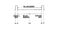
このようにして,動画記録が行われている途中にシャッタ・レリーズ・ボタン3が押されると,連写モードに移行し,高画質の静止画像が得られることとなる(時刻t3〜t4,t5〜t6,t7〜t8,t9〜t10,t11〜t12の静止画処理時間)。また,連写における静止画の撮像の合間には動画像データの記録が行われる(時刻t4〜t5,t6〜t7,t8〜t9,t10〜t11の動画挿入期間)。さらに,連写における静止画の撮像の合間に動画像が液晶表示画面8上に表示されるので,液晶表示画面8に表示されている画像を見ながら主被写体を追うことができるようになる。動きのある主被写体を連写すると場合であっても主被写体を見失うことを未然に防止できる。静止画の撮像は,図5に示すように静止画処理期間(動画挿入期間の間の期間)の前半の静止画撮像時間(時刻t5〜t20)に行なわれ,得られた静止画像データについての信号処理は後半の信号処理期間(時刻t20〜t6)に行われる。もっとも後述するように信号処理は動画挿入期間内に行なわれるようにしてもよい。
【0051】
時刻t12において,設定された連写枚数の連写が終了すると(ステップ54でNO),現在の連写枚数nがリセットされる(ステップ55)。
【0052】
その後,ステップ45の処理に戻り再び動画記録モードに変更される。再び動画像データの記録が行われるようになる。
【0053】
時刻t13において,2回目の決定スイッチ10の押下があると(ステップ46でYES),動画記録モードが終了し,メモリ・カード34への動画像データの記録も停止する。
【0054】
動画記録モード中に連写が割り込まれると,図3に示したように動画ファイルと連写ファイルとがメモリ・カード34に記録されることとなる。再生時においては,動画像ファイルによって表される動画像の中に,連写ファイルによって表される静止画像が静止画が記録された時間に対応して挿入されるように動画像データが生成される。動画中において,静止画像を表す駒の駒落ちが無くなるので,再生される動画はより滑らかなものとなる。再生表示において,静止画像の大きさ(解像度)は,動画を構成する一駒の画像の大きさにリサイズされるのはいうまでもない。
【0055】
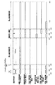
図8は,他の実施例を示すもので,ディジタル・スチル・カメラ1において動画撮像モードが設定されたときのタイム・チャート,図9は,図8に示すタイム・チャートのΔt2間を拡大して示すタイム・チャートである。図9においては,図8に示されている静止画信号処理回路への転送/読出し,静止画のための圧縮/伸長回路への転送/読出しについてのタイム・チャートは省略されている。
【0056】
上述した実施例においては,静止画処理期間に静止画の撮像(静止画撮像期間)と信号処理(信号処理期間)とを行っているため連写間隔(連写期間)を短くするのに制限がある。静止画処理期間が比較的長くなるので,連写モードの間,液晶表示画面8に表示される静止画処理期間の割合が多くなり,動画像の動きが滑らかとならないことがある。
【0057】
図8および図9に示すものは,静止画処理期間の時間を短くし,連写モードにおいて静止画が表示されている時間を短縮するものである。具体的には,信号処理は,動画挿入期間の間に行われる。静止画撮像期間が静止画処理期間と同じとなり,連写モードにおいて静止画が表示されている時間が短くなる。比較的滑らかな動画が表示されることとなる。
【0058】
この実施例においては,上述したディジタル・スチル・カメラ1における撮像バスのバス幅よりも画像バスのバス幅が広いものが用いられる(図2参照)。たとえば,撮像バスのバス幅が12ビット(同時に送信できるデータ量が12ビット)のものが用いられ,画像バスのバス幅は32ビットのものが用いられる。撮像バスのバス幅よりも画像バスのバス幅の方が広いから,クロック周波数の高いクロック・パルスを用いることにより同じデータ量であれば撮像バスにおけるデータの転送時間よりもさらに一層短い時間で画像バス内をデータを転送できる。たとえば撮像バス内をデータが転送するときには,12MHzのクロック周波数をもつクロック・パルスにもとづいて行われるが,画像バス内をデータが転送するときには, 100MHzのクロック周波数をもつクロック・パルスにもとづいて行われる。
【0059】
1水平走査ライン分の画像データが撮像バスを介して画像入力制御回路24に入力する。画像入力制御回路24において,12ビットのバス幅に適した配列から32ビットのバス幅に適した配列となるように画像データの配列変換が行われる。配列変換された画像データが画像バスを介して上述したようにフレーム・メモリ32に記憶されることとなる。
【0060】
動画撮像モードが設定されており,かつ決定スイッチ10が押されたことにより動画記録モードとなっているものとする。また,時刻t35の時点でシャッタ・レリーズ・ボタン3が押されるものとする。
【0061】
時刻t35の時点においてシャッタ・レリーズ・ボタン3が押される前までは動画記録モードとなっているから,CCD22は動画読み出しモードに設定され,1/60秒(=16.6ms)周期で被写体の撮像が繰り返されている。動画用の被写体を撮像するときには(動画撮影モード,動画記録モード),1/60秒周期で垂直同期信号が出力され,静止画用の被写体を撮像するときには(静止画撮影モード),垂直同期信号の出力間隔は120msとなる。
【0062】
動画記録モードとなっているときに,時刻t31において垂直同期信号が出力され,得られた動画像データが時刻t32からt33までの間に1水平走査ライン分ずつ画像入力制御回路24から出力されフレーム・メモリ32に与えられる。また,時刻t32からt33までの間に1水平走査ライン分ずつ動画像データがフレーム・メモリ32から読み出され,動画信号処理回路25に与えられる。また,動画信号処理された動画像データが動画信号処理回路25から読み出され,フレーム・メモリ32に与えられる。さらに,時刻t32からt33までの間に1水平走査ライン分ずつフレーム・メモリ32から読み出され,圧縮/伸長回路27においてMPEG圧縮が行われ,再びフレーム・メモリ32に与えられる。圧縮された画像データはフレーム・メモリ32から読み出され,画像バスを介して記録/読み出し制御回路30に与えられ,メモリ・カード34に記録される。
【0063】
より詳しくは,図9に示すように,時刻t51からt52の間に画像入力制御回路24から出力された1水平走査ライン分の画像データが画像バスを介してフレーム・メモリ32に与えられる。時刻t52からt53までの間にフレーム・メモリ32に記憶された1水平走査ライン分の画像データが読み出され,動画信号処理回路25に入力し,動画信号処理されて画像バスを介してフレーム・メモリ32に与えられる。時刻t53からt54までの間にフレーム・メモリ32から1ライン分の画像データが読み出され,圧縮/伸長回路27に与えられる。時刻t54からt55までの間にフレーム・メモリ32から1ライン分の画像データが読み出され,記録/読み出し制御回路30に与えられる。このように,画像データの転送を時分割で行っているので,画像バス上で画像データが衝突することを未然に防止できる。しかも,画像バスは,撮像バスよりもそのバス幅が広く転送速度も速いので水平同期信号の出力周期内で1ライン分の画像データを複数種類の回路に転送させることができるようになる。水平同期信号の周期はt51〜t56の約63.5μsである。
【0064】
時刻t36においてシャッタ・レリーズ・ボタン3が押されると,CCD22は静止画読み出しモードとされる。得られた静止画像データは,時刻t37からt39までの間に静止画信号処理回路26への転送および静止画信号処理回路26からの読み出しが行われる。また,時刻t39からt41までの間に圧縮/伸長回路27への転送および圧縮/伸長回路27からの読み出しが行われる。さらに,時刻t41からt43までの間に記録/読み出し制御回路30に与えられ,メモリ・カード34に記録されることとなる。
【0065】
静止画像データについても動画像データと同様に,図9に示すように時分割で画像データの転送および各回路からの読み出しが行われているのはいうまでもない。
【0066】
このように連写における動画挿入期間の間には静止画撮像が行われ,静止画像データの信号処理は行われていないので,動画挿入期間の間隔が短くなる。また,連写速度も向上させることができる。
【図面の簡単な説明】
【図1】ディジタル・スチル・カメラを背面から見た斜視図である。
【図2】ディジタル・スチル・カメラの電気的構成を示すブロック図である。
【図3】メモリ・カードの記録領域を示している。
【図4】動画記録モードが設定されたときのタイム・チャートを示している。
【図5】動画記録モードが設定されたときのタイム・チャートを示している。
【図6】ディジタル・スチル・カメラの処理手順を示すフローチャートである。
【図7】ディジタル・スチル・カメラの処理手順を示すフローチャートである。
【図8】動画記録モードが設定されたときのタイム・チャートを示している。
【図9】動画記録モードが設定されたときのタイム・チャートを示している。
【符号の説明】
1 ディジタル・スチル・カメラ
3 シャッタ・レリーズ・ボタン
4 モード・スイッチ
8 液晶表示画面
10 決定スイッチ
20 CPU
21 駆動回路
24 画像入力制御回路
25 動画信号処理回路
26 静止画信号処理回路
28 表示制御回路
29 表示装置
30 記録/読み出し制御回路
31 DMAコントローラ
32 フレーム・メモリ
33 SDRAMコントローラ
34 メモリ・カード[0001]
【Technical field】
The present invention relates to a digital movie camera and an operation control method thereof.
[0002]
BACKGROUND OF THE INVENTION
The digital movie camera captures a subject at a constant cycle (for example, 1/60 second) and records moving image data obtained by the imaging on a recording medium such as a video tape or a memory card. In some digital movie cameras, the subject is imaged at the timing when the shutter release button is pressed by pressing the shutter release button during recording of moving image data, and the obtained image data is stored on a recording medium. Some have a still recording function (so-called digital movie still camera).
[0003]
However, such a digital movie still camera adds data indicating that the shutter release button has been pressed among the images of each frame constituting the movie to the image captured when the movie was pressed. To do. The resolution of images constituting a moving image is the same as the resolution of still images. In addition, continuous shooting is not considered during video recording.
[0004]
DISCLOSURE OF THE INVENTION
An object of the present invention is to enable recording of high-quality still image data for a plurality of frames obtained by continuous shooting on a recording medium even when a moving image recording mode for recording moving image data is set. To do.
[0005]
The digital movie camera according to the present invention captures a subject image at a constant cycle in accordance with the setting of an imaging means including a solid-state electronic image pickup device that captures a subject and outputs image data representing the subject image. The first driving means for driving the solid-state electronic image pickup device so as to output the moving image data, and the image data read out from the solid-state electronic image pickup device under the driving by the first driving means. A moving image recording control means for recording moving image data on a recording medium, and in response to the setting of the continuous shooting mode during operation in the moving image recording mode, the subject is continuously shot at a timing corresponding to the continuous shooting interval, Second driving means for driving the solid-state electronic image pickup device so as to output image data (the first driving means and the second driving means may be the same), and the second driving means Characterized in that it comprises a still image recording control means for recording on said recording medium the still image read image data from the solid-state electronic image sensing device based on the driving by motion means as still image data.
[0006]
The present invention also provides an operation control method for the digital movie camera. That is, in this method, the subject is imaged using an imaging means including a solid-state electronic image sensor, image data representing the subject image is obtained, and the subject image is captured at a certain period according to the setting of the moving image recording mode. The solid-state electronic image pickup device is driven so as to pick up an image and output moving image data, and image data read out from the solid-state electronic image pickup device is recorded as moving image data on a recording medium, and is operating in the moving image recording mode. In response to the setting of the continuous shooting mode, the solid-state electronic image sensor is driven so as to continuously shoot the subject at a timing corresponding to the continuous shooting interval and output still image data. The read image data is recorded on the recording medium as still image data.
[0007]
According to the present invention, when the moving image recording mode is set, the subject is imaged at a fixed period and the moving image is read (for moving image recording, preferably image data obtained from the effective pixel area of the solid-state electronic image sensor). The solid-state electronic imaging device is driven so that a part is read by thinning or the like. Image data output from the solid-state electronic image sensor is recorded on a recording medium as moving image data. If the continuous shooting mode is set during operation in this video recording mode, the subject is continuously shot at a timing corresponding to the continuous shooting interval, and still image readout (for still image recording, preferably solid-state electronic imaging) The solid-state electronic image pickup device is driven so as to read out substantially all image data obtained from the effective pixel region of the device. When the operation in the continuous shooting mode is finished (when the continuous shooting is finished), the solid-state electronic image pickup device is driven so that the subject is picked up at a constant cycle and the moving image is read out again.
[0008]
Even if the moving image recording mode is set and the moving image data is recorded on the recording medium, the continuous shooting mode is set when the continuous shooting mode is set. Even during operation in the moving image recording mode, still image data for a plurality of frames obtained by continuous shooting can be recorded on a recording medium. In particular, in the continuous shooting mode, the solid-state electronic image pickup device is driven so as to start moving image reading and still image reading, so that still image data for a plurality of frames with high resolution can be obtained. Needless to say, if the number of continuous shots is one, a single shot is practically obtained, and still image data for one frame with high image quality can be obtained.
[0009]
Drive control means for controlling the first drive means so as to capture an image of the subject at a constant period and read the moving image within a part of the moving image insertion period in the continuous shooting interval may be further provided.
[0010]
Since the subject is imaged at a fixed period even during a part of the moving image insertion period during the continuous shooting interval, moving image data is obtained, and the obtained moving image data is recorded on the recording medium. Video data can be recorded even during continuous shooting. During the period when the continuous shooting mode is set, the recording of the moving image data is not stopped, but the moving image data is recorded in a part of the continuous shooting interval, so the obtained moving image data is played back. Even so, you can get a smooth motion video.
[0011]
You may further provide the display apparatus which displays the to-be-photographed image represented with the image data output from the said imaging means. In this case, when the moving image recording mode is set, a moving image represented by moving image data obtained by imaging is displayed. If the continuous shooting mode is set while the moving image recording mode is set, a moving image is displayed during the moving image insertion period even during continuous shooting. During continuous shooting, not only a still image is displayed, but a moving image is displayed during a certain period, so it is relatively easy to follow the main subject while watching the moving image displayed on the display device. Can do.
[0012]
A buffer memory for sequentially and temporarily storing image data for a plurality of frames output from the imaging means, a reading means for reading out the image data stored in the buffer memory and giving it to the display device, and the continuous shooting period In the still image processing period excluding the moving image insertion period, the subject image captured during the moving image insertion period immediately before the still image processing period (preferably, the subject image captured at the end of the immediately preceding moving image insertion period) You may further provide the read-out control means which controls the said read-out means so that it may display on a display apparatus.
[0013]
The still image processing period includes, for example, a still image imaging period necessary for imaging a subject and reading image data from the solid-state electronic image sensor, and signal processing for performing signal processing on the image data output from the solid-state electronic image sensor. Including period.
[0014]
As described above, the still image processing period is equal to, for example, a still image capturing period necessary for imaging a subject and reading image data from the solid-state electronic image sensor. In this case, it is preferable to further include a signal processing circuit that performs signal processing on the image data output from the solid-state electronic image sensor in the moving image insertion period immediately after the still image capturing period.
[0015]
Since the signal processing period by the signal processing circuit and the moving image insertion period can be set to overlap, the continuous shooting interval can be shortened. In addition, since the interval of the moving image insertion period can be shortened, a smooth moving image can be obtained.
[0016]
The apparatus may further comprise related data recording control means for recording data relating the moving image data and the still image data on the recording medium.
[0017]
Since the related data is recorded on the recording medium, the still image represented by the still image data obtained by continuous shooting can be inserted into the image position extracted by continuous shooting. A smooth video will be obtained.
[0018]
[Explanation of Examples]
FIG. 1 shows an embodiment of the present invention, and is a perspective view of a digital still camera having a function of recording moving image data as viewed from the back. The digital still camera according to this embodiment can set the continuous shooting mode while the moving image recording mode for recording moving image data is set as will be described in detail later. You can interrupt the recording of movies and record continuously.
[0019]
On the upper surface of the digital
[0020]
A liquid
[0021]
When a reverse feed command (command to return one playback frame, command to move the cursor for specifying a thumbnail image to the left when a large number of thumbnail images are displayed, etc.) is input on the liquid
[0022]
On the right side of the liquid
[0023]
FIG. 2 is a block diagram showing an electrical configuration of the digital
[0024]
The entire configuration of the digital
[0025]
Output signals from the
[0026]
The digital
[0027]
When the still image capturing mode or the moving image capturing mode is set, the subject is imaged by the CCD 22 at a period of 1/60 second, and a video signal representing the subject image is output. The CCD 22 is driven by the
[0028]
The video signal output from the CCD 22 is subjected to predetermined preprocessing such as white balance adjustment and gamma correction in the preprocessing and analog / digital conversion circuit 23, and converted from the analog video signal to RGB digital image data. The digital image data is temporarily stored in the frame memory 32 controlled by the SDRAM controller 33 via the image input control circuit 24 controlled by the DMA controller 31. The image data is read from the frame memory 32 and given to the display control circuit 28. The
[0029]
If the determination switch 10 is pressed while the moving image capturing mode is set, the moving image recording mode is set. In the moving image recording mode, as described above, the image data output from the image input control circuit 24 and temporarily stored in the frame memory 32 is input to the moving image signal processing circuit 25 under the control of the DMA controller 31. To do. In the moving image signal processing circuit 25, luminance data and color difference data generation processing from the RGB digital image data and other predetermined moving image signal processing are executed. The generated luminance data and color difference data are given to the frame memory 32 and temporarily stored again.
[0030]
Luminance data and color difference data are read from the frame memory 32 and input to the compression / decompression circuit 27. The compression / decompression circuit 27 performs MPEG (moving picture experts group) compression. The compressed luminance data and color difference data are sequentially recorded on the
[0031]
When the
[0032]
The digital image data is read from the frame memory 32 and input to the still image signal processing circuit 26. In the still image signal processing circuit 26, predetermined still image signal processing such as processing for generating luminance data and color difference data from digital image data and generation processing of high-frequency luminance data for obtaining a high-resolution still image is performed. The generated luminance data and color difference data are given to the frame memory 32 and stored again. Luminance data and color difference data are read from the frame memory 32 and compressed by a compression / expansion circuit 27 in JPEG (joint photographic experts group). The compressed luminance data and color difference data are given to the frame memory 32 and stored again.
[0033]
The compressed luminance data and color difference data are read from the frame memory 32 and input to the recording / reading control circuit 30. Luminance data and color difference data compressed by the recording / reading control circuit 30 are recorded in the
[0034]
When the reproduction mode is set, the image data recorded on the
[0035]
FIG. 3 shows the recording area of the
[0036]
As shown on the left side, the
[0037]
As shown in the center, the moving image file includes a header recording area and a data recording area. Header information is recorded in the header recording area, and moving image data is recorded in the data recording area.
[0038]
As shown on the right side, the header information includes basic information and user information. Basic information includes the number of movie frames (number of frames constituting a movie represented by one movie file), imaging cycle (1/60 seconds), and number of pixels constituting movie frames (horizontal direction of one frame image constituting a movie) And the number of pixels in the vertical direction) are recorded. The user information includes a set number F of moving image insertion frames (described in detail later), a set number of consecutive shots N (5 frames as described above), and the number of still image pixels (still images in the still image shooting mode). The number of pixels in each of the horizontal direction and the vertical direction when the image is obtained), the still image recording start time, and the continuous shooting file recording address when there is a corresponding continuous shooting file are recorded.
[0039]
4 is a time chart when the moving image capturing mode is set in the digital
[0040]
In the digital
[0041]
First, it is assumed that the moving image capturing mode is set by the
[0042]
Assume that the determination switch 10 is pressed by the user at time t2 (YES in step 43). Then, the digital
[0043]
The subject is imaged at a period of 1/60 seconds, and the image data obtained as described above is signal-processed, compressed, and sequentially recorded on the
[0044]
When the second determination switch 10 is pressed (YES in step 46), the moving image recording mode ends. If the second determination switch 10 is not pressed (NO in step 46), it is determined whether the
[0045]
Even if the digital
[0046]
When the
[0047]
Subsequently, it is confirmed whether or not the current moving image insertion frame number f is less than the set moving image insertion frame number F (step 50). When the
[0048]
Since the first frame has been picked up in the continuous shooting mode, the current continuous shooting number n is incremented, and the current moving image insertion frame number f is reset (step 53). The number f of moving image insertion frames is reset because moving image data is recorded in the
[0049]
If the current continuous shooting number n is less than or equal to the set continuous shooting number N (YES in step 54), the processing from step 45 is repeated to perform the remaining continuous shooting. Between the shooting and recording of the preceding still image and the shooting and recording of the subsequent still image, the moving image data until the reset number f of the current moving image insertion frame reaches the set number F of moving image insertion frames again. Is repeated. When the first frame image is recorded in the continuous shooting mode, the current continuous shooting number n is 1, so that the result of
[0050]
In this way, when the
[0051]
When continuous shooting of the set number of continuous shots is completed at time t12 (NO in step 54), the current number of continuous shots n is reset (step 55).
[0052]
Thereafter, the process returns to the process of step 45 and is again changed to the moving image recording mode. Recording of moving image data is performed again.
[0053]
If the determination switch 10 is pressed for the second time at time t13 (YES in step 46), the moving image recording mode is terminated and recording of moving image data on the
[0054]
When continuous shooting is interrupted during the moving image recording mode, the moving image file and the continuous shooting file are recorded on the
[0055]
FIG. 8 shows another embodiment, which is a time chart when the moving image capturing mode is set in the digital
[0056]
In the above-described embodiments, since still image capturing (still image capturing period) and signal processing (signal processing period) are performed during the still image processing period, the continuous shooting interval (continuous shooting period) is limited to be shortened. There is. Since the still image processing period becomes relatively long, the ratio of the still image processing period displayed on the liquid
[0057]
FIG. 8 and FIG. 9 shorten the time of the still image processing period and shorten the time during which the still image is displayed in the continuous shooting mode. Specifically, signal processing is performed during the moving image insertion period. The still image capturing period is the same as the still image processing period, and the time during which the still image is displayed in the continuous shooting mode is shortened. A relatively smooth video will be displayed.
[0058]
In this embodiment, the image bus having a wider bus width than the imaging bus in the digital
[0059]
Image data for one horizontal scanning line is input to the image input control circuit 24 via the imaging bus. In the image input control circuit 24, the arrangement of the image data is converted so that the arrangement suitable for the bus width of 12 bits is changed to the arrangement suitable for the bus width of 32 bits. The array-converted image data is stored in the frame memory 32 through the image bus as described above.
[0060]
It is assumed that the moving image capturing mode is set and the moving image recording mode is set when the determination switch 10 is pressed. It is assumed that the
[0061]
Since the moving image recording mode is set before the
[0062]
When the moving image recording mode is set, a vertical synchronization signal is output at time t31, and the obtained moving image data is output from the image input control circuit 24 by one horizontal scanning line from time t32 to t33. • Given to memory 32. Also, moving image data for one horizontal scanning line is read from the frame memory 32 and supplied to the moving image signal processing circuit 25 from time t32 to t33. In addition, moving image data that has undergone moving image signal processing is read out from the moving image signal processing circuit 25 and applied to the frame memory 32. Further, during the period from time t32 to t33, the data is read from the frame memory 32 by one horizontal scanning line, subjected to MPEG compression in the compression / decompression circuit 27, and supplied to the frame memory 32 again. The compressed image data is read from the frame memory 32, supplied to the recording / reading control circuit 30 via the image bus, and recorded on the
[0063]
More specifically, as shown in FIG. 9, the image data for one horizontal scanning line output from the image input control circuit 24 between times t51 and t52 is applied to the frame memory 32 via the image bus. Image data for one horizontal scanning line stored in the frame memory 32 from time t52 to t53 is read out and input to the moving image signal processing circuit 25, where the moving image signal is processed and the frame data is transmitted via the image bus. Given to memory 32. One line of image data is read from the frame memory 32 and supplied to the compression / decompression circuit 27 between times t53 and t54. From time t54 to t55, one line of image data is read from the frame memory 32 and supplied to the recording / reading control circuit 30. As described above, since the transfer of the image data is performed in a time division manner, it is possible to prevent the image data from colliding on the image bus. Moreover, the image bus has a wider bus width and a higher transfer speed than the imaging bus, so that one line of image data can be transferred to a plurality of types of circuits within the output period of the horizontal synchronization signal. The period of the horizontal synchronizing signal is about 63.5 μs from t51 to t56.
[0064]
When the
[0065]
Needless to say, as with moving image data, still image data is transferred in time division and read out from each circuit as shown in FIG.
[0066]
In this manner, still image capturing is performed during the moving image insertion period in continuous shooting, and signal processing of still image data is not performed, so the interval of the moving image insertion period is shortened. Also, the continuous shooting speed can be improved.
[Brief description of the drawings]
FIG. 1 is a perspective view of a digital still camera as viewed from the back.
FIG. 2 is a block diagram showing an electrical configuration of a digital still camera.
FIG. 3 shows a recording area of a memory card.
FIG. 4 shows a time chart when a moving image recording mode is set.
FIG. 5 shows a time chart when the moving image recording mode is set.
FIG. 6 is a flowchart showing a processing procedure of the digital still camera.
FIG. 7 is a flowchart showing a processing procedure of the digital still camera.
FIG. 8 shows a time chart when the moving image recording mode is set.
FIG. 9 shows a time chart when the moving image recording mode is set.
[Explanation of symbols]
1 Digital still camera
3 Shutter release button
4 Mode switch
8 LCD display screen
10 Decision switch
20 CPU
21 Drive circuit
24 Image input control circuit
25 Video signal processing circuit
26 Still image signal processing circuit
28 Display control circuit
29 Display device
30 Recording / reading control circuit
31 DMA controller
32 frame memory
33 SDRAM controller
34 Memory card
Claims (8)
動画記録モードが設定されたことに応じて,被写体像を一定周期で撮像し,動画読み出しをして上記固体電子撮像素子の有効画素領域から得られる画像データの一部である動画データを出力するように上記固体電子撮像素子を駆動する第1の駆動手段,
上記動画記録モードによる動作中に連写モードが設定されたことに応じて,連写間隔に応じたタイミングで被写体を連写し,静止画読み出しをして上記固体電子撮像素子の有効画素領域から得られる画像データを実質的にすべて読み出して得られる画像データである静止画データを出力するように上記固体電子撮像素子を駆動する第2の駆動手段,
上記第2の駆動手段による駆動のもとに上記固体電子撮像素子から静止画読み出しされた画像データを静止画像データとして上記記録媒体に記録する静止画像記録制御手段,
上記第2の駆動手段による連写の合間に,被写体を一定周期で撮像し,動画読み出しをして上記固体電子撮像素子の有効画素領域から得られる画像データの一部である動画データを出力するように上記固体電子撮像素子を駆動する第3の駆動手段,ならびに
上記第1の駆動手段および上記第3の駆動手段による駆動のもとに上記固体電子撮像素子から動画読み出しされた画像データを動画像データとして記録媒体に記録する動画像記録制御手段,
を備えたディジタル・ムービ・カメラ。An imaging means including a solid-state electronic imaging device for imaging a subject and outputting image data representing the subject image;
In response to setting of the moving image recording mode, the subject image is captured at a fixed period, the moving image is read out, and moving image data that is a part of the image data obtained from the effective pixel area of the solid-state electronic image sensor is output. First driving means for driving the solid-state electronic image sensor,
When the continuous shooting mode is set during operation in the moving image recording mode, the subject is continuously shot at a timing corresponding to the continuous shooting interval, and the still image is read out from the effective pixel area of the solid-state electronic image sensor. Second driving means for driving the solid-state electronic image pickup device so as to output still image data, which is image data obtained by reading out substantially all of the image data obtained ,
Still image recording control means for recording image data read out from the solid-state electronic image sensor as still image data on the recording medium under the driving of the second driving means;
During continuous shooting by the second driving means, the subject is imaged at a fixed period, the moving image is read, and moving image data that is a part of image data obtained from the effective pixel area of the solid-state electronic image sensor is output. A third driving means for driving the solid-state electronic image sensor, and
Moving image recording control means for recording image data read out from the solid-state electronic image sensor as moving image data on a recording medium under the driving of the first driving means and the third driving means;
Digital movie camera with
上記バッファ・メモリに記憶された画像データを読み出し,上記表示装置に与える読み出し手段,および
上記連写期間中における上記動画挿入期間を除く静止画処理期間は,上記静止画処理期間直前の動画挿入期間に撮像された被写体像を上記表示装置に表示するように上記読み出し手段を制御する読み出し制御手段,
をさらに備えた請求項3に記載のディジタル・ムービ・カメラ。A buffer memory for temporarily and temporarily storing image data for a plurality of frames output from the imaging means;
Reading means for reading image data stored in the buffer memory and giving it to the display device, and a still image processing period excluding the moving image insertion period in the continuous shooting period is a moving image insertion period immediately before the still image processing period Reading control means for controlling the reading means so as to display the subject image picked up on the display device;
The digital movie camera according to claim 3, further comprising:
請求項4に記載のディジタル・ムービ・カメラ。The still image processing period includes a still image imaging period necessary for imaging a subject and reading image data from a solid-state electronic image sensor, and a signal processing period for performing signal processing on the image data output from the solid-state electronic image sensor. Including
The digital movie camera according to claim 4.
上記静止画撮像期間直後の上記動画挿入期間に上記固体電子撮像素子から出力された画像データを信号処理する信号処理回路をさらに備えた請求項4に記載のディジタル・ムービ・カメラ。The still image processing period is equal to the still image capturing period necessary for imaging the subject and reading the image data from the solid-state electronic image sensor,
5. The digital movie camera according to claim 4, further comprising a signal processing circuit that performs signal processing on image data output from the solid-state electronic image sensor during the moving image insertion period immediately after the still image capturing period.
動画記録モードが設定されたことに応じて,被写体像を一定周期で撮像し,動画読み出しをして上記固体電子撮像素子の有効画素領域から得られる画像データの一部である動画データを出力するように上記固体電子撮像素子を駆動する第1の駆動を行い,
上記動画記録モードによる動作中に連写モードが設定されたことに応じて,連写間隔に応じたタイミングで被写体を連写し,静止画読み出しをして上記固体電子撮像素子の有効画素領域から得られる画像データを実質的にすべて読み出して得られる画像データである静止画データを出力するように上記固体電子撮像素子を駆動する第2の駆動を行い,
第2の駆動により上記固体電子撮像素子から静止画読み出しされた画像データを静止画像データとして上記記録媒体に記録し,
上記第2の駆動による連写の合間に,被写体を一定周期で撮像し,動画読み出しをして上記固体電子撮像素子の有効画素領域から得られる画像データの一部である動画データを出力するように上記固体電子撮像素子を駆動する第3の駆動を行い,
上記第1の駆動および第3の駆動により上記固体電子撮像素子から動画読み出しされた画像データを動画像データとして記録媒体に記録する,
ディジタル・ムービ・カメラの動作制御方法。Using an imaging means including a solid-state electronic image sensor, image the subject, obtain image data representing the subject image,
In response to setting of the moving image recording mode, the subject image is captured at a fixed period, the moving image is read out, and moving image data that is a part of the image data obtained from the effective pixel area of the solid-state electronic image sensor is output. The first drive for driving the solid-state electronic image sensor is performed as follows :
In response to the continuous shooting mode is set in operation by the dynamic equi recording mode, consecutive images of the subject at the timing corresponding to the continuous shooting interval, the effective pixel region of the solid-state electronic image sensing device and a still image read A second drive for driving the solid-state electronic image sensor so as to output still image data, which is image data obtained by reading substantially all of the image data obtained from
The second drive is recorded on the recording medium the still image read image data from the solid-state electronic image sensing device as still image data,
In between the continuous shooting by the second driving, the subject is imaged at a constant period, the moving image is read, and moving image data that is a part of image data obtained from the effective pixel area of the solid-state electronic image sensor is output. And a third drive for driving the solid-state electronic image sensor,
Image data read out from the solid-state electronic image sensor by the first driving and the third driving is recorded as moving image data on a recording medium;
Operation control method of digital movie camera.
Priority Applications (2)
| Application Number | Priority Date | Filing Date | Title |
|---|---|---|---|
| JP2001356838A JP3973408B2 (en) | 2001-11-22 | 2001-11-22 | Digital movie camera and operation control method thereof |
| US10/300,823 US7528865B2 (en) | 2001-11-22 | 2002-11-21 | Digital movie camera and method of controlling operations thereof |
Applications Claiming Priority (1)
| Application Number | Priority Date | Filing Date | Title |
|---|---|---|---|
| JP2001356838A JP3973408B2 (en) | 2001-11-22 | 2001-11-22 | Digital movie camera and operation control method thereof |
Publications (3)
| Publication Number | Publication Date |
|---|---|
| JP2003158653A JP2003158653A (en) | 2003-05-30 |
| JP2003158653A5 JP2003158653A5 (en) | 2005-02-17 |
| JP3973408B2 true JP3973408B2 (en) | 2007-09-12 |
Family
ID=19168283
Family Applications (1)
| Application Number | Title | Priority Date | Filing Date |
|---|---|---|---|
| JP2001356838A Expired - Fee Related JP3973408B2 (en) | 2001-11-22 | 2001-11-22 | Digital movie camera and operation control method thereof |
Country Status (2)
| Country | Link |
|---|---|
| US (1) | US7528865B2 (en) |
| JP (1) | JP3973408B2 (en) |
Families Citing this family (53)
| Publication number | Priority date | Publication date | Assignee | Title |
|---|---|---|---|---|
| JP4299410B2 (en) * | 1999-09-28 | 2009-07-22 | Hoya株式会社 | Electronic still camera recording operation control device |
| JP2004201282A (en) | 2002-12-06 | 2004-07-15 | Casio Comput Co Ltd | Photographing device and photographing method |
| US7312821B2 (en) * | 2003-06-03 | 2007-12-25 | Hewlett-Packard Development Company, L.P. | Time-sliced still image generation |
| JP3992659B2 (en) * | 2003-08-08 | 2007-10-17 | 三洋電機株式会社 | Imaging device |
| JP4160883B2 (en) | 2003-09-02 | 2008-10-08 | 富士フイルム株式会社 | Image recording apparatus and image recording method |
| US20050168589A1 (en) * | 2004-01-30 | 2005-08-04 | D. Amnon Silverstein | Method and system for processing an image with an image-capturing device |
| JP2005223557A (en) * | 2004-02-05 | 2005-08-18 | Casio Comput Co Ltd | Photographing instrument and program therefor |
| JP4039386B2 (en) * | 2004-04-21 | 2008-01-30 | コニカミノルタオプト株式会社 | Imaging sensor and imaging apparatus |
| US8902320B2 (en) | 2005-01-31 | 2014-12-02 | The Invention Science Fund I, Llc | Shared image device synchronization or designation |
| US20070236505A1 (en) * | 2005-01-31 | 2007-10-11 | Searete Llc, A Limited Liability Corporation Of The State Of Delaware | Resampling of transformed shared image techniques |
| US7920169B2 (en) | 2005-01-31 | 2011-04-05 | Invention Science Fund I, Llc | Proximity of shared image devices |
| US9124729B2 (en) | 2005-01-31 | 2015-09-01 | The Invention Science Fund I, Llc | Shared image device synchronization or designation |
| US20060187228A1 (en) * | 2005-01-31 | 2006-08-24 | Searete Llc, A Limited Liability Corporation Of The State Of Delaware | Sharing including peripheral shared image device |
| US20060171603A1 (en) * | 2005-01-31 | 2006-08-03 | Searete Llc, A Limited Liability Corporation Of The State Of Delaware | Resampling of transformed shared image techniques |
| US20060174203A1 (en) | 2005-01-31 | 2006-08-03 | Searete Llc, A Limited Liability Corporation Of The State Of Delaware | Viewfinder for shared image device |
| US9489717B2 (en) | 2005-01-31 | 2016-11-08 | Invention Science Fund I, Llc | Shared image device |
| US7876357B2 (en) * | 2005-01-31 | 2011-01-25 | The Invention Science Fund I, Llc | Estimating shared image device operational capabilities or resources |
| US9325781B2 (en) | 2005-01-31 | 2016-04-26 | Invention Science Fund I, Llc | Audio sharing |
| US9910341B2 (en) | 2005-01-31 | 2018-03-06 | The Invention Science Fund I, Llc | Shared image device designation |
| US20060173972A1 (en) * | 2005-01-31 | 2006-08-03 | Searete Llc, A Limited Liability Corporation Of The State Of Delaware | Audio sharing |
| US9082456B2 (en) | 2005-01-31 | 2015-07-14 | The Invention Science Fund I Llc | Shared image device designation |
| US8606383B2 (en) | 2005-01-31 | 2013-12-10 | The Invention Science Fund I, Llc | Audio sharing |
| JP4148228B2 (en) * | 2005-02-10 | 2008-09-10 | ソニー株式会社 | Image recording apparatus, image reproduction control apparatus, image recording / reproduction control apparatus, processing method of these apparatuses, and program causing computer to execute the method |
| KR100713404B1 (en) * | 2005-03-24 | 2007-05-04 | 삼성전자주식회사 | Apparatus and method for photographing during video recording |
| JP4035543B2 (en) * | 2005-04-04 | 2008-01-23 | キヤノン株式会社 | Imaging device |
| JP4137085B2 (en) * | 2005-04-21 | 2008-08-20 | キヤノン株式会社 | Imaging device |
| US8253821B2 (en) * | 2005-10-31 | 2012-08-28 | The Invention Science Fund I, Llc | Degradation/preservation management of captured data |
| US9001215B2 (en) | 2005-06-02 | 2015-04-07 | The Invention Science Fund I, Llc | Estimating shared image device operational capabilities or resources |
| US8964054B2 (en) | 2006-08-18 | 2015-02-24 | The Invention Science Fund I, Llc | Capturing selected image objects |
| US9967424B2 (en) | 2005-06-02 | 2018-05-08 | Invention Science Fund I, Llc | Data storage usage protocol |
| US8681225B2 (en) | 2005-06-02 | 2014-03-25 | Royce A. Levien | Storage access technique for captured data |
| US9819490B2 (en) | 2005-05-04 | 2017-11-14 | Invention Science Fund I, Llc | Regional proximity for shared image device(s) |
| US7782365B2 (en) * | 2005-06-02 | 2010-08-24 | Searete Llc | Enhanced video/still image correlation |
| US9451200B2 (en) | 2005-06-02 | 2016-09-20 | Invention Science Fund I, Llc | Storage access technique for captured data |
| US7872675B2 (en) | 2005-06-02 | 2011-01-18 | The Invention Science Fund I, Llc | Saved-image management |
| US20070098348A1 (en) * | 2005-10-31 | 2007-05-03 | Searete Llc, A Limited Liability Corporation Of The State Of Delaware | Degradation/preservation management of captured data |
| US10003762B2 (en) | 2005-04-26 | 2018-06-19 | Invention Science Fund I, Llc | Shared image devices |
| US9942511B2 (en) | 2005-10-31 | 2018-04-10 | Invention Science Fund I, Llc | Preservation/degradation of video/audio aspects of a data stream |
| US9191611B2 (en) | 2005-06-02 | 2015-11-17 | Invention Science Fund I, Llc | Conditional alteration of a saved image |
| JP4902136B2 (en) | 2005-04-28 | 2012-03-21 | キヤノン株式会社 | Imaging apparatus, imaging method, and program |
| JP4724577B2 (en) * | 2005-05-11 | 2011-07-13 | キヤノン株式会社 | Imaging apparatus and control method thereof |
| US20060274153A1 (en) * | 2005-06-02 | 2006-12-07 | Searete Llc, A Limited Liability Corporation Of The State Of Delaware | Third party storage of captured data |
| JP4336387B2 (en) * | 2007-01-15 | 2009-09-30 | パナソニック株式会社 | Imaging device |
| JP2009038649A (en) * | 2007-08-02 | 2009-02-19 | Panasonic Corp | Signal processing circuit and imaging apparatus |
| US20090066808A1 (en) * | 2007-09-11 | 2009-03-12 | Sanyo Electric Co., Ltd. | Image-data processing apparatus and data-processing circuit |
| TWI366148B (en) * | 2007-12-21 | 2012-06-11 | Asia Optical Co Inc | A method of image data processing |
| JP4931845B2 (en) * | 2008-03-18 | 2012-05-16 | 富士フイルム株式会社 | Imaging apparatus and captured image display control method |
| JP5224925B2 (en) * | 2008-06-18 | 2013-07-03 | キヤノン株式会社 | Imaging device |
| JP5251684B2 (en) * | 2009-04-01 | 2013-07-31 | 富士通セミコンダクター株式会社 | Image processing device |
| JP5573145B2 (en) * | 2009-12-16 | 2014-08-20 | ソニー株式会社 | Image processing system, image processing apparatus, image processing method, and program |
| JP5911298B2 (en) * | 2011-12-27 | 2016-04-27 | キヤノン株式会社 | Imaging apparatus and control method thereof |
| JP5783929B2 (en) * | 2012-02-20 | 2015-09-24 | キヤノン株式会社 | Imaging device |
| JP5866674B1 (en) | 2014-07-29 | 2016-02-17 | パナソニックIpマネジメント株式会社 | Imaging device |
Family Cites Families (22)
| Publication number | Priority date | Publication date | Assignee | Title |
|---|---|---|---|---|
| US5589943A (en) * | 1991-08-20 | 1996-12-31 | Canon Kabushiki Kaisha | Apparatus for recording digital still image signals and analog still image signals in respective recording areas |
| US5734424A (en) * | 1990-08-08 | 1998-03-31 | Canon Kabushiki Kaisha | Image pickup apparatus capable of providing moving video signal and still video signal |
| JP3081018B2 (en) * | 1991-06-06 | 2000-08-28 | キヤノン株式会社 | Still image recording device |
| JPH0522686A (en) | 1991-07-15 | 1993-01-29 | Canon Inc | Magnetic recorder |
| JPH07135592A (en) | 1993-11-11 | 1995-05-23 | Canon Inc | Image pickup device |
| US5828406A (en) * | 1994-12-30 | 1998-10-27 | Eastman Kodak Company | Electronic camera having a processor for mapping image pixel signals into color display pixels |
| US6359649B1 (en) * | 1995-04-04 | 2002-03-19 | Canon Kabushiki Kaisa | Video camera integrated with still camera |
| US5899575A (en) * | 1996-09-04 | 1999-05-04 | Hitachi, Ltd. | Video capture device, video recording/playing apparatus having the video capture device attached thereto, and video input device |
| JP3787398B2 (en) * | 1996-11-27 | 2006-06-21 | キヤノン株式会社 | Image processing apparatus and method |
| US6937273B1 (en) * | 1997-05-28 | 2005-08-30 | Eastman Kodak Company | Integrated motion-still capture system with indexing capability |
| US6122003A (en) * | 1997-08-22 | 2000-09-19 | Flashpoint Technology, Inc. | Method and apparatus for changing operating modes of an image capture device |
| US6359643B1 (en) * | 1998-08-31 | 2002-03-19 | Intel Corporation | Method and apparatus for signaling a still image capture during video capture |
| JP3932006B2 (en) | 1998-12-02 | 2007-06-20 | 株式会社日立製作所 | Imaging device |
| US6665453B2 (en) * | 1999-03-16 | 2003-12-16 | Intel Corporation | Multi-resolution support for video images |
| JP2000308076A (en) | 1999-04-26 | 2000-11-02 | Hitachi Ltd | Image pickup device |
| JP2000352759A (en) | 1999-06-10 | 2000-12-19 | Olympus Optical Co Ltd | Electronic camera |
| JP4518346B2 (en) | 1999-08-25 | 2010-08-04 | カシオ計算機株式会社 | Electronic camera and photographing method |
| JP2001078137A (en) | 1999-09-01 | 2001-03-23 | Olympus Optical Co Ltd | Electronic camera |
| EP1081946A3 (en) * | 1999-09-03 | 2004-01-02 | Victor Company Of Japan, Limited | Recording apparatus and recording method of video signal |
| JP2001292357A (en) * | 2000-04-07 | 2001-10-19 | Asahi Optical Co Ltd | Continuous mode image processing apparatus |
| JP4245782B2 (en) * | 2000-07-03 | 2009-04-02 | オリンパス株式会社 | Imaging device |
| US6992707B2 (en) * | 2002-03-06 | 2006-01-31 | Hewlett-Packard Development Company, L.P. | Delayed encoding based joint video and still image pipeline with still burst mode |
-
2001
- 2001-11-22 JP JP2001356838A patent/JP3973408B2/en not_active Expired - Fee Related
-
2002
- 2002-11-21 US US10/300,823 patent/US7528865B2/en not_active Expired - Fee Related
Also Published As
| Publication number | Publication date |
|---|---|
| JP2003158653A (en) | 2003-05-30 |
| US7528865B2 (en) | 2009-05-05 |
| US20030095191A1 (en) | 2003-05-22 |
Similar Documents
| Publication | Publication Date | Title |
|---|---|---|
| JP3973408B2 (en) | Digital movie camera and operation control method thereof | |
| KR102077967B1 (en) | Electronic device | |
| JP2003158653A5 (en) | ||
| US6903770B1 (en) | Digital camera which produces a single image based on two exposures | |
| JP2003324644A (en) | Video signal processing apparatus, image display control method, storage medium and program | |
| US6697106B1 (en) | Apparatus for processing image signals representative of a still picture and moving pictures picked up | |
| US7369683B2 (en) | Imaging device | |
| JP4556195B2 (en) | Imaging device, moving image playback device, and program | |
| US20070035654A1 (en) | Video camera apparatus | |
| JP2000041171A (en) | Image recorder | |
| JP4200551B2 (en) | Imaging apparatus, image processing apparatus, imaging method, and image processing method | |
| JP2007166539A (en) | Imaging apparatus, imaging method, program and storage medium | |
| US7428013B2 (en) | Electronic camera having solid-state image pickup device | |
| JP2929956B2 (en) | Creation method of still image data in video camera | |
| JP2000041192A5 (en) | ||
| JP2000023007A (en) | Image input device and method and memory medium | |
| JP2002125145A (en) | Image pickup device and drive method for solid-state image pickup element | |
| JPH07322114A (en) | Image pickup device | |
| JP3768987B2 (en) | Imaging device | |
| JP2003060954A (en) | Digital camera | |
| JP2000253280A (en) | Image pickup device | |
| JP2001086373A (en) | Image pickup unit, method for controlling image pickup unit and computer-readable storage medium | |
| JP2000041161A (en) | Image recording and reproducing device and its data display method | |
| EP0920774A1 (en) | Image pick-up method and apparatus using the image pick-up method | |
| JP2005167531A (en) | Image processor |
Legal Events
| Date | Code | Title | Description |
|---|---|---|---|
| A521 | Request for written amendment filed |
Free format text: JAPANESE INTERMEDIATE CODE: A523 Effective date: 20040312 |
|
| A621 | Written request for application examination |
Free format text: JAPANESE INTERMEDIATE CODE: A621 Effective date: 20040312 |
|
| A977 | Report on retrieval |
Free format text: JAPANESE INTERMEDIATE CODE: A971007 Effective date: 20060119 |
|
| A131 | Notification of reasons for refusal |
Free format text: JAPANESE INTERMEDIATE CODE: A131 Effective date: 20060124 |
|
| A521 | Request for written amendment filed |
Free format text: JAPANESE INTERMEDIATE CODE: A523 Effective date: 20060323 |
|
| A02 | Decision of refusal |
Free format text: JAPANESE INTERMEDIATE CODE: A02 Effective date: 20060808 |
|
| A521 | Request for written amendment filed |
Free format text: JAPANESE INTERMEDIATE CODE: A523 Effective date: 20061005 |
|
| A711 | Notification of change in applicant |
Free format text: JAPANESE INTERMEDIATE CODE: A712 Effective date: 20061207 |
|
| A911 | Transfer to examiner for re-examination before appeal (zenchi) |
Free format text: JAPANESE INTERMEDIATE CODE: A911 Effective date: 20061212 |
|
| TRDD | Decision of grant or rejection written | ||
| A01 | Written decision to grant a patent or to grant a registration (utility model) |
Free format text: JAPANESE INTERMEDIATE CODE: A01 Effective date: 20070606 |
|
| A61 | First payment of annual fees (during grant procedure) |
Free format text: JAPANESE INTERMEDIATE CODE: A61 Effective date: 20070612 |
|
| R150 | Certificate of patent or registration of utility model |
Free format text: JAPANESE INTERMEDIATE CODE: R150 |
|
| FPAY | Renewal fee payment (event date is renewal date of database) |
Free format text: PAYMENT UNTIL: 20100622 Year of fee payment: 3 |
|
| FPAY | Renewal fee payment (event date is renewal date of database) |
Free format text: PAYMENT UNTIL: 20100622 Year of fee payment: 3 |
|
| FPAY | Renewal fee payment (event date is renewal date of database) |
Free format text: PAYMENT UNTIL: 20110622 Year of fee payment: 4 |
|
| FPAY | Renewal fee payment (event date is renewal date of database) |
Free format text: PAYMENT UNTIL: 20110622 Year of fee payment: 4 |
|
| FPAY | Renewal fee payment (event date is renewal date of database) |
Free format text: PAYMENT UNTIL: 20120622 Year of fee payment: 5 |
|
| FPAY | Renewal fee payment (event date is renewal date of database) |
Free format text: PAYMENT UNTIL: 20120622 Year of fee payment: 5 |
|
| FPAY | Renewal fee payment (event date is renewal date of database) |
Free format text: PAYMENT UNTIL: 20130622 Year of fee payment: 6 |
|
| R250 | Receipt of annual fees |
Free format text: JAPANESE INTERMEDIATE CODE: R250 |
|
| R250 | Receipt of annual fees |
Free format text: JAPANESE INTERMEDIATE CODE: R250 |
|
| LAPS | Cancellation because of no payment of annual fees |