JP3973317B2 - Manufacturing method of wheel bearing device - Google Patents
Manufacturing method of wheel bearing device Download PDFInfo
- Publication number
- JP3973317B2 JP3973317B2 JP11509199A JP11509199A JP3973317B2 JP 3973317 B2 JP3973317 B2 JP 3973317B2 JP 11509199 A JP11509199 A JP 11509199A JP 11509199 A JP11509199 A JP 11509199A JP 3973317 B2 JP3973317 B2 JP 3973317B2
- Authority
- JP
- Japan
- Prior art keywords
- bearing device
- wheel bearing
- wheel
- inner member
- mounting flange
- Prior art date
- Legal status (The legal status is an assumption and is not a legal conclusion. Google has not performed a legal analysis and makes no representation as to the accuracy of the status listed.)
- Expired - Lifetime
Links
Images


Description
【0001】
【発明の属する技術分野】
この発明は、自動車の車輪軸受装置の製造方法に関するものである。
【0002】
【従来の技術】
自動車の車輪軸受装置には、駆動輪用のものと、非駆動輪用のものとがあり、それぞれ種々の型式のものがある。その一例として、駆動輪用の車輪軸受装置を図12に示す。即ち、その基本構造は、内周に複列の転走面3a、3bを有する外方部材3と、その各々の転走面3a、3bに対向する転走面1a、1bを有する内方部材1と、上記外方部材3と内方部材1との間に介在する複列の転動体8とからなり、内方部材1に車輪取付けフランジ2を設けたものである。また、図12に示す例では、内方部材1は内周に駆動軸の嵌合孔9を有する。なお、内方部材1の複列の転走面1a、1bのうち、アウター側の転走面1aを内方部材1の外周に直接形成しており、インナー側の転走面1bを別体の内輪に形成している。ここで、アウター側の転走面は車輪取付けフランジに近い方の軌道面をいい、その反対にインナー側の転走面は遠い方の軌道面をいう。
【0003】
ところで、車輪軸受メーカーから自動車メーカーの自動車組立て工場に納入された車輪軸受装置の車輪取付けフランジ2の側面2aには、自動車組立て工場において別部品として納入されたブレーキロータ20がボルト18によって固定される。ところが、組立て後に、ブレーキロータ20の側面21に面振れがあると、自動車の高速化に伴って、高速走行からのブレーキ時の振動の原因となったり、ブレーキの偏摩耗の原因になったりする。また、面振れの状態によっては、低速時でもこのブレーキ時の振動が生じる場合がある。
【0004】
従来、かかるブレーキロータ20の側面21の面振れを解消するために、自動車組立て工場において、車輪軸受メーカーから納入された車輪軸受装置の車輪取付けフランジ2に、別部品として納入されたブレーキロータ20を組付ける時に車輪取付けフランジ2の面振れとブレーキロータ20の側面21の面振れを位相合わせする等の調整を行っているが、かかる方法は甚だ面倒で作業性が悪い。
【0005】
【発明が解決しようとする課題】
そこで、この発明は、自動車の高速化に伴なって発生するブレーキロータ20の面振れによる振動及びブレーキの偏摩耗を防止すること、並びに自動車組立て工場において面倒なブレーキロータ20の振れ調整を行う必要のない、信頼性の高い車輪軸受装置の製造方法を提供しようとするものである。
【0006】
【課題を解決するための手段】
この発明は、内周に複列の転走面を有する外方部材と、その各々の転走面に対向する転走面を有する内方部材と、上記外方部材と内方部材との間に介在する複列の転動体とからなり、上記外方部材又は内方部材のいずれか一方に車輪取付けフランジを設け、この車輪取付けフランジの一方の側面にブレーキロータの固定面を形成する車輪軸受装置の製造方法において、上記車輪取付けフランジを設けた外方部材又は内方部材の転走面側の円筒部を旋削により形成した後、この円筒部の円筒面を基準に車輪取付けフランジのブレーキロータ固定面を切削仕上げするようにしたものである。
【0007】
ブレーキロータ固定面を転走面側の円筒部を基準に切削仕上げを行うと、ブレーキロータ固定面が、内方部材又は外方部材の回転軸心に対して正確に加工できるので、ブレーキロータ固定面の面振れを最小限に抑制することができる。
【0008】
したがって、自動車組立て工場における面倒なブレーキロータの面振れの調整が不要になる。
【0009】
また、ブレーキロータ固定面の表面粗さを細かく、3Ra以下に仕上げることにより、ブレーキロータの面振れをさらに抑制することができる。
【0010】
この3Ra以下という表面粗さは、車輪取付けフランジを一次旋削して形成した後、転走面を基準にして内方部材又は外方部材を回転させながら一方の側面のブレーキロータの固定面を二次旋削することにより得ることができる。
【0011】
【発明の実施の形態】
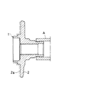
この発明に係る製造方法は、例えば、車輪取付けフランジ2を設けた内方部材1の転走面1a及びインナー側の端部14の外周面を一次旋削により形成した後、内方部材1の外周の転送面1a及びインナー側端部14の外周面を高周波焼入れし、その後、図1に示すように、内方部材1の転走面1aと同軸で旋削されたインナー側の端部を、NC旋盤のチャッキング装置Aに固定して、車輪取付けフランジ2のブレーキロータ20の固定面となる側面2aを二次旋削するものである。これにより、転走面を基準にブレーキロータ20の側面2aが二次旋削される。
【0012】
次に、この発明によって製造する自動車の車輪軸受装置は、例えば、図2に示すように、内周に複列の転走面3a、3bを有する外方部材3と、その各々の転走面3a、3bに対向する転走面1a、1bを有する内方部材1と、上記外方部材3と内方部材1との間に介在する複列の転動体8とからなり、上記内方部材1に車輪取付けフランジ2を設けた構造であり、この車輪取付けフランジ2の側面2aに、ブレーキロータ20がボルト18によって固定されるようになっている。具体的には、図2乃至図8に示すような、駆動輪用のものと、図9乃至図11に示すように、駆動軸が取付けられない非駆動輪用のものとがあり、以下にその具体例を説明する。
【0013】
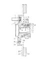
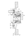
図2に示す車輪軸受装置は、駆動輪用の車輪軸受装置であってこの発明によって製造する第1の実施例である。この図2の内方部材1は、内周に駆動軸と嵌合するスプラインを設けた嵌合孔9を形成している。また、内方部材1の複列の転走面1a、1bのうち、アウター側の転走面1aを、内方部材1の外周に直接形成しており、インナー側の転走面1bを別体の内輪15に形成し、この内輪15をハブ輪14の端部の肩部に嵌め入れている。また、この図2の内方部材1のハブ輪14には、車輪取付けフランジ2が一体に形成され、そのアウター側の側面の中央に、ホイールパイロット10が形成されている。この車輪取付けフランジ2には、ホイールを固定するハブボルト7のボルト孔11が形成され、また、このアウター側の側面2aにブレーキロータ20がボルト18によって固定されるようになっている。また、この図2の外方部材3は、内周に複列の転走面3a、3bを直接形成している。また、外方部材3には、車体に固定するボルト孔12を有するフランジ4が一体に形成されているとともに、その両端部内周面には、軸受内部を密封するシール部材19が装着されている。そして、この図2の例では、ブレーキロータ20を固定するアウター側の側面2aが二次旋削によって、表面粗さが3Ra以下の細かさに仕上げられており、他方の側面2bの表面粗さは一次旋削の状態の3〜6Raである。
【0014】
次に、図3に示す車輪軸受装置は、駆動輪用の車輪軸受装置であって、この発明の第2の実施例であり、上記第1の実施例における別体の内輪15が、等速自在継手の車軸の外径に圧入されるように構成されている。この例でも、ブレーキロータ20を固定するアウター側の側面2aが二次旋削されている。
【0015】
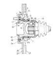
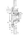
次に、図4に示す車輪軸受装置は、駆動輪用の車輪軸受装置であって、この発明の第3の実施例である。このものは、内方部材1を、等速自在継手13の外輪と一体に構成したものである。また、この内方部材1には、外周に複列の転走面1a、1bが直接形成されている。また、この図4の内方部材1のアウター側には、ホイールパイロット10と、車輪取付けフランジ2が一体に形成されている。一方、図4の外方部材3には、内周に複列の転走面3a、3bが直接形成されている。また、この外方部材3の外面には、車体に固定するボルト孔12を有するフランジ4が一体に形成されている。この図4の例では、車輪取付けフランジ2の側面2aにブレーキロータ20がボルト18によって固定されるようになっており、このブレーキロータ20を固定する車輪取付けフランジ2の側面2aが内方部材1の転走面1aを基準に二次旋削によって表面粗さが3Ra以下に仕上げられている。
【0016】
図5に示す車輪軸受装置も、駆動輪用の車輪軸受装置であってこの発明の第4の実施例である。この図5の内方部材1の複列の転走面1a、1bは、別体の2つの内輪15、15によって形成され、内方部材1に車輪取付けフランジ2が形成され、この側面2aにブレーキロータ20がボルト18によって固定されている。一方、外方部材3は、図2乃至図4に示す車輪軸受装置と同様に、内周に複列の転走面3a、3bを直接形成したものである。この第4の実施例では、内方部材1の車輪取付けフランジ2の側面2aを二次旋削している。
【0017】
図6に示す車輪軸受装置も、駆動輪用の車輪軸受装置であってこの発明の第5の実施例である。この図6の内方部材1は、図5に示すものと同様に、駆動軸に装着される内方部材1は、その複列の転走面1a、1bを別体の2つの内輪15、15に形成している。また、外方部材3は、車体に固定するボルト孔12を有するフランジ4を形成したハウジング16と、複列の転走面3a、3bを形成した外輪17とによって形成している。この第5の実施例も、内方部材1の車輪取付けフランジ2の側面2aを二次旋削している。
【0018】
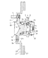
次に、図7に示す車輪軸受装置は、駆動輪用の車輪軸受装置で、ブレーキロータ20を車輪取付けフランジ2のインナー側に固定したこの発明の第6の実施例である。
【0019】
この第6の実施例のように、ブレーキロータ20を車輪取付けフランジ2のインナー側に取付ける場合、車輪取付けフランジ2のインナー側の側面2bはホイール取付け面でないので、ブレーキロータ20の取付け面22を、図8に示すように、内方部材1の車輪取付けフランジ2の外径面がブレーキロータ20のブレーキパイロットになる段部25の付いた形状に形成している。そして、上記ブレーキロータ20の取付け面22には、ブレーキロータ20を固定するためのボルト18の固定孔24だけを形成し、ハブボルト7が取付け面22にかからないようにハブボルト7の位置に切欠部23を形成している。このように、ブレーキロータ20の取付け面22に、切欠部23を形成しておくと、ハブボルト7にナットを締め付けた際に、ホイールが軸方向に変形しても、ブレーキロータ20にはその影響が全く出ないので、ブレーキロータ20の面振れをより低減することができる。この第6の実施例では、インナー側の側面2bを、二次旋削によって表面粗さをアウター側の側面2aよりも細かく、3Ra以下に仕上げている。
【0020】
この第6の実施例のように、ブレーキロータ20を車輪取付けフランジ2のインナー側に取付けるようにすることは、他の実施例にも適宜適用することは可能である。その場合には、車輪取付けフランジ2のインナー側の側面2bを、内方部材1の転走面1aを基準に二次旋削により、表面粗さが3Ra以下になるように仕上げる。
【0021】
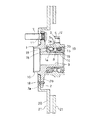
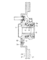
次に、図9に示す車輪軸受装置は、非駆動輪用の車輪軸受装置であってこの発明の第7の実施例である。この図9の内方部材1は、複列の転走面1a、1bのうちのアウター側の転走面1aを外面に直接形成し、インナー側の端部に装着される別体の内輪15にインナー側の転走面1bを形成している。この内方部材1には、車輪取付けフランジ2が一体に形成され、この車輪取付けフランジ2の側面2aにブレーキロータ20がボルト18によって固定されている。この車輪取付けフランジ2の側面2aは、内方部材1の転走面1aを基準に二次切削により表面粗さが3Ra以下に仕上げられている。また、図9の外方部材3は、内周に複列の転走面3a、3bを直接形成しており、外面に車体に固定するためのボルト孔12を有するフランジ4を形成している。なお、内方部材1のインナー側には、ねじ部30が形成されており、ナット31で締結することにより内輪15を固定するとともに、軸受に予圧を付与し軸受剛性を得ている。さらに、ハブキャップ32によってインナー側を封止している。
【0022】
図10に示す車輪軸受装置は、非駆動輪用の車輪軸受装置であってこの発明の第8の実施例である。このものは、外方部材3に車輪取付けフランジ2を設け、外方部材3の内面に複列の転走面3a、3bを直接形成している。そして、外方部材3の内側に、外面に転走面1a、1bを形成した内方部材1(内輪15、15)が設けられている。この図10の例では、外方部材3の車輪取付けフランジ2のアウター側の側面2aにブレーキロータ20が固定されている。
【0023】
図11に示す車輪軸受装置は、この発明の第9の実施例である。この車輪軸受装置は、外方部材3を、車輪取付けフランジ2を有し、内周に複列の転走面3a、3bを有する別体の外輪17を圧入することによって形成している。そして、外面に転走面1a、1bを形成した内方部材1(内輪15、15)が、転動体8を介して外方部材3の内側に設けられている。この図11の例では、外方部材3の車輪取付けフランジ2のアウター側の側面2aにブレーキロータ20がボルト18によって固定されている。
【0024】
第8及び第9の実施例では、ブレーキロータ20を固定する車輪取付けフランジ2のアウター側の側面2aが、外方部材3の転走面3a、3bを基準に二次旋削により表面粗さが3Ra以下に仕上げられている。
【0025】
なお、以上の各実施例の車輪軸受装置において、シールは符号19によって示され、その他同一構成の部分には同一符号を付している。
【0026】
また、上記の各実施例において、車輪取付けフランジ2の側面2a又は2bの二次旋削は、一次旋削した外方部材3を高周波焼入れした後に行っている。外方部材3の転走面3a、3bと同軸で旋削される内周面をチャッキングして二次旋削することにより、転走面を基準に側面2aを旋削することになる。
【0027】
【発明の効果】
以上のように、この発明によれば、車輪取付けフランジの一方の側面のブレーキロータ固定面を、転走面を基準に二次旋削により細かい表面粗さに仕上げているので、ブレーキロータの面振れが抑制された高品質の車輪軸受装置を得ることができる。
【図面の簡単な説明】
【図1】二次旋削による仕上げ工程を示す図
【図2】この発明によって製造する駆動輪用の車輪軸受装置の第1の実施例を示す断面図
【図3】この発明によって製造する駆動輪用の車輪軸受装置の第2の実施例を示す断面図
【図4】この発明によって製造する駆動輪用の車輪軸受装置の第3の実施例を示す断面図
【図5】この発明によって製造する駆動輪用の車輪軸受装置の第4の実施例を示す断面図
【図6】この発明によって製造する駆動輪用の車輪軸受装置の第5の実施例を示す断面図
【図7】この発明によって製造する駆動輪用の車輪軸受装置の第6の実施例を示す断面図
【図8】上記第6の実施例のブレーキロータの一部分を示す正面図
【図9】この発明によって製造する非駆動輪用の車輪軸受装置の第7の実施例を示す断面図
【図10】この発明によって製造する非駆動輪用の車輪軸受装置の第8の実施例を示す断面図
【図11】この発明によって製造する非駆動輪用の車輪軸受装置の第9の実施例を示す断面図
【図12】従来例の断面図
【符号の説明】
A チャッキング装置
1 内方部材
1a、1b 転走面
2 車輪取付けフランジ
2a、2b 側面
3 外方部材
3a、3b 転走面
4 フランジ
7 ハブボルト
8 転動体
9 嵌合孔
10 ホイールパイロット
11 ボルト孔
12 ボルト孔
13 等速自在継手
14 ハブ輪
15 内輪
16 ハウジング
17 外輪
18 ボルト
19 シール
20 ブレーキロータ
21 側面
22 取付け面
23 切欠部
24 固定孔
25 段部
30 ねじ部
31 ナット
32 ハブキャップ[0001]
BACKGROUND OF THE INVENTION
The present invention relates to a method for manufacturing a wheel bearing device for an automobile.
[0002]
[Prior art]
There are two types of wheel bearing devices for automobiles, one for driving wheels and the other for non-driving wheels. As an example, a wheel bearing device for driving wheels is shown in FIG. That is, the basic structure is an
[0003]
By the way, the
[0004]
Conventionally, in order to eliminate the surface runout of the
[0005]
[Problems to be solved by the invention]
Therefore, the present invention needs to prevent vibrations due to surface runout of the
[0006]
[Means for Solving the Problems]
The present invention provides an outer member having a double row rolling surface on the inner periphery, an inner member having a rolling surface facing each of the rolling surfaces, and the outer member and the inner member. A wheel bearing flange having a wheel mounting flange on one of the outer member and the inner member, and a fixed surface of the brake rotor formed on one side surface of the wheel mounting flange. In the manufacturing method of the apparatus, after the cylindrical part on the rolling surface side of the outer member or the inner member provided with the wheel mounting flange is formed by turning, the brake rotor of the wheel mounting flange is based on the cylindrical surface of the cylindrical part. The fixed surface is finished by cutting.
[0007]
If the brake rotor fixing surface is cut and finished with the cylindrical part on the rolling surface side as a reference, the brake rotor fixing surface can be accurately machined with respect to the rotation axis of the inner member or the outer member. Surface runout can be minimized.
[0008]
This eliminates the need for troublesome adjustment of the runout of the brake rotor in the automobile assembly plant.
[0009]
Further, by finely finishing the surface roughness of the brake rotor fixing surface to 3 Ra or less, the surface vibration of the brake rotor can be further suppressed.
[0010]
The surface roughness of 3Ra or less is formed by first turning the wheel mounting flange, and then rotating the inner member or the outer member on the basis of the rolling surface while rotating the fixing surface of the brake rotor on one side. It can be obtained by the next turning.
[0011]
DETAILED DESCRIPTION OF THE INVENTION
In the manufacturing method according to the present invention, for example, the outer peripheral surface of the
[0012]
Next, an automobile wheel bearing device manufactured according to the present invention includes, as shown in FIG. 2, for example, an
[0013]
The wheel bearing device shown in FIG. 2 is a wheel bearing device for a drive wheel and is a first embodiment manufactured by the present invention. The
[0014]
Next, the wheel bearing device shown in FIG. 3 is a wheel bearing device for driving wheels, which is a second embodiment of the present invention, in which the separate
[0015]
Next, the wheel bearing device shown in FIG. 4 is a wheel bearing device for driving wheels, which is a third embodiment of the present invention. In this structure, the
[0016]
The wheel bearing device shown in FIG. 5 is also a wheel bearing device for driving wheels and is a fourth embodiment of the present invention. The double-
[0017]
The wheel bearing device shown in FIG. 6 is also a wheel bearing device for driving wheels, and is a fifth embodiment of the present invention. The
[0018]
Next, the wheel bearing device shown in FIG. 7 is a wheel bearing device for driving wheels, which is a sixth embodiment of the present invention in which the
[0019]
When the
[0020]
Mounting the
[0021]
Next, the wheel bearing device shown in FIG. 9 is a wheel bearing device for non-driving wheels and is a seventh embodiment of the present invention. The
[0022]
The wheel bearing device shown in FIG. 10 is a wheel bearing device for non-driven wheels and is an eighth embodiment of the present invention. In this device, a
[0023]
The wheel bearing device shown in FIG. 11 is a ninth embodiment of the present invention. In this wheel bearing device, the
[0024]
In the eighth and ninth embodiments, the
[0025]
In the wheel bearing device of each of the above embodiments, the seal is indicated by
[0026]
Further, in each of the above-described embodiments, the secondary turning of the
[0027]
【The invention's effect】
As described above, according to the present invention, the brake rotor fixing surface on one side of the wheel mounting flange is finished to a fine surface roughness by secondary turning with reference to the rolling surface. Can be obtained.
[Brief description of the drawings]
FIG. 1 is a view showing a finishing process by secondary turning. FIG. 2 is a cross-sectional view showing a first embodiment of a wheel bearing device for a drive wheel manufactured according to the present invention. FIG. 3 is a drive wheel manufactured according to the present invention. FIG. 4 is a cross-sectional view showing a second embodiment of a wheel bearing device for a drive wheel manufactured according to the present invention. FIG. 5 is a cross-sectional view showing a third embodiment of a wheel bearing device for a drive wheel manufactured according to the present invention. FIG. 6 is a cross-sectional view showing a fourth embodiment of a wheel bearing device for a drive wheel. FIG. 6 is a cross-sectional view showing a fifth embodiment of a wheel bearing device for a drive wheel manufactured according to the present invention. Sectional view showing a sixth embodiment of a wheel bearing device for a drive wheel to be manufactured. FIG. 8 is a front view showing a part of a brake rotor of the sixth embodiment. FIG. 9 is a non-drive wheel manufactured by the present invention. Sectional view showing a seventh embodiment of the wheel bearing device for a vehicle [Fig. FIG. 11 is a sectional view showing an eighth embodiment of a wheel bearing device for non-driving wheels manufactured according to the present invention. FIG. 11 shows a ninth embodiment of a wheel bearing device for non-driving wheels manufactured according to the present invention. Sectional view [Fig. 12] Sectional view of conventional example [Explanation of symbols]
A
Claims (9)
Priority Applications (9)
| Application Number | Priority Date | Filing Date | Title |
|---|---|---|---|
| JP11509199A JP3973317B2 (en) | 1999-04-22 | 1999-04-22 | Manufacturing method of wheel bearing device |
| KR1019990049512A KR20000035349A (en) | 1998-11-11 | 1999-11-09 | Automotive wheel bearing assembly and method for manufacturing the same |
| US09/437,149 US6250814B1 (en) | 1909-04-22 | 1999-11-10 | Automotive wheel bearing assembly and method for manufacturing the same |
| EP99122393A EP1000772B1 (en) | 1998-11-11 | 1999-11-10 | Automotive wheel bearing assembly and method for manufacturing the same |
| DE69939092T DE69939092D1 (en) | 1998-11-11 | 1999-11-10 | Wheel bearing unit for motor vehicles and method of manufacture |
| US09/850,271 US6357925B2 (en) | 1998-11-11 | 2001-05-08 | Automotive wheel bearing assembly and method for manufacturing the same |
| KR1020070076421A KR20070094703A (en) | 1998-11-11 | 2007-07-30 | Automotive wheel bearing assembly and method for manufacturing the same |
| KR1020080011113A KR100858316B1 (en) | 1998-11-11 | 2008-02-04 | A constant-velocity joint for a driven wheel |
| KR1020080075174A KR101037742B1 (en) | 1998-11-11 | 2008-07-31 | Method for manufacturing automotive wheel bearing assembly |
Applications Claiming Priority (1)
| Application Number | Priority Date | Filing Date | Title |
|---|---|---|---|
| JP11509199A JP3973317B2 (en) | 1999-04-22 | 1999-04-22 | Manufacturing method of wheel bearing device |
Publications (2)
| Publication Number | Publication Date |
|---|---|
| JP2000301401A JP2000301401A (en) | 2000-10-31 |
| JP3973317B2 true JP3973317B2 (en) | 2007-09-12 |
Family
ID=14653989
Family Applications (1)
| Application Number | Title | Priority Date | Filing Date |
|---|---|---|---|
| JP11509199A Expired - Lifetime JP3973317B2 (en) | 1909-04-22 | 1999-04-22 | Manufacturing method of wheel bearing device |
Country Status (1)
| Country | Link |
|---|---|
| JP (1) | JP3973317B2 (en) |
Families Citing this family (14)
| Publication number | Priority date | Publication date | Assignee | Title |
|---|---|---|---|---|
| AU2003280828A1 (en) * | 2003-01-29 | 2004-08-23 | Nsk Ltd. | Wheel bearing unit and method of manufacturing the bearing unit |
| US7524115B2 (en) | 2003-12-16 | 2009-04-28 | Ntn Corporation | Rolling bearing |
| JP4526998B2 (en) * | 2005-04-22 | 2010-08-18 | Ntn株式会社 | Drive wheel bearing device |
| US7913374B2 (en) | 2005-08-09 | 2011-03-29 | Ntn Corporation | Processing method for brake rotor-equipped wheel bearing devices |
| JP4994617B2 (en) * | 2005-08-09 | 2012-08-08 | Ntn株式会社 | Processing method of wheel bearing device |
| JP4554467B2 (en) * | 2005-08-09 | 2010-09-29 | Ntn株式会社 | Processing method of wheel bearing device with brake rotor |
| JP4855005B2 (en) * | 2005-08-09 | 2012-01-18 | Ntn株式会社 | Processing method of wheel bearing device |
| JP4948856B2 (en) * | 2006-03-08 | 2012-06-06 | Ntn株式会社 | Brake rotor machining method for drive wheel bearing unit |
| JP4993342B2 (en) * | 2006-05-08 | 2012-08-08 | Ntn株式会社 | Wheel bearing device |
| JP2008207803A (en) * | 2008-03-24 | 2008-09-11 | Jtekt Corp | Bearing device and manufacturing method therefor |
| JP6107205B2 (en) | 2013-02-15 | 2017-04-05 | 株式会社ジェイテクト | Hub wheel manufacturing method and vehicle bearing device manufacturing method |
| JP7047388B2 (en) * | 2018-01-12 | 2022-04-05 | 株式会社ジェイテクト | Wheel bearing device and its manufacturing method |
| JP7047389B2 (en) * | 2018-01-12 | 2022-04-05 | 株式会社ジェイテクト | Wheel bearing device and its manufacturing method |
| JP7172822B2 (en) * | 2019-04-15 | 2022-11-16 | 株式会社ジェイテクト | Machining method for outer ring flange of wheel bearing device |
-
1999
- 1999-04-22 JP JP11509199A patent/JP3973317B2/en not_active Expired - Lifetime
Also Published As
| Publication number | Publication date |
|---|---|
| JP2000301401A (en) | 2000-10-31 |
Similar Documents
| Publication | Publication Date | Title |
|---|---|---|
| US6250814B1 (en) | Automotive wheel bearing assembly and method for manufacturing the same | |
| JP4484132B2 (en) | Hub assembly with minimal runout and manufacturing method thereof | |
| JP3973317B2 (en) | Manufacturing method of wheel bearing device | |
| US9839962B2 (en) | Processing method for brake rotor-equipped wheel bearing devices | |
| JP2002323056A (en) | Wheel bearing device | |
| US6309110B1 (en) | Wheel bearing assembly with brake rotor | |
| US6626580B2 (en) | Wheel bearing assembly | |
| JPH08253165A (en) | Integral type wheel end assembly | |
| US20080063335A1 (en) | Rolling Bearing Assembly | |
| JP4994617B2 (en) | Processing method of wheel bearing device | |
| JP4116729B2 (en) | Wheel bearing device | |
| JP4699977B2 (en) | Wheel bearing device | |
| WO2006087838A1 (en) | Method of cutting braking surface of wheel bearing device with brake rotor | |
| EP1470936A1 (en) | Bearing unit for vehicle wheel | |
| JP4439334B2 (en) | Wheel bearing device | |
| WO2022264877A1 (en) | Vehicular power device and vehicle wheel bearing device with power generator | |
| JP5254938B2 (en) | Wheel bearing device | |
| JP2005335455A (en) | Bearing device for wheel | |
| JP2007237332A (en) | Brake rotor machining method of bearing unit for drive wheel | |
| JP2007223459A (en) | Method of manufacturing power transmission mechanism | |
| JP2007046685A (en) | Processing method of wheel bearing device with brake rotor | |
| JP2001105807A (en) | Brake rotor and wheel bearing device therewith | |
| KR20000047825A (en) | Wheel bearing assembly with brake rotor | |
| JP2000203208A (en) | Wheel bearing device | |
| JP2002317824A (en) | Manufacturing method for rolling bearing unit for driving wheel, and driving unit for wheel |
Legal Events
| Date | Code | Title | Description |
|---|---|---|---|
| A621 | Written request for application examination |
Free format text: JAPANESE INTERMEDIATE CODE: A621 Effective date: 20040312 |
|
| A131 | Notification of reasons for refusal |
Free format text: JAPANESE INTERMEDIATE CODE: A131 Effective date: 20070213 |
|
| A521 | Written amendment |
Free format text: JAPANESE INTERMEDIATE CODE: A523 Effective date: 20070416 |
|
| TRDD | Decision of grant or rejection written | ||
| A01 | Written decision to grant a patent or to grant a registration (utility model) |
Free format text: JAPANESE INTERMEDIATE CODE: A01 Effective date: 20070529 |
|
| A61 | First payment of annual fees (during grant procedure) |
Free format text: JAPANESE INTERMEDIATE CODE: A61 Effective date: 20070612 |
|
| R150 | Certificate of patent or registration of utility model |
Free format text: JAPANESE INTERMEDIATE CODE: R150 |
|
| FPAY | Renewal fee payment (event date is renewal date of database) |
Free format text: PAYMENT UNTIL: 20100622 Year of fee payment: 3 |
|
| FPAY | Renewal fee payment (event date is renewal date of database) |
Free format text: PAYMENT UNTIL: 20100622 Year of fee payment: 3 |
|
| FPAY | Renewal fee payment (event date is renewal date of database) |
Free format text: PAYMENT UNTIL: 20110622 Year of fee payment: 4 |
|
| FPAY | Renewal fee payment (event date is renewal date of database) |
Free format text: PAYMENT UNTIL: 20110622 Year of fee payment: 4 |
|
| FPAY | Renewal fee payment (event date is renewal date of database) |
Free format text: PAYMENT UNTIL: 20120622 Year of fee payment: 5 |
|
| FPAY | Renewal fee payment (event date is renewal date of database) |
Free format text: PAYMENT UNTIL: 20120622 Year of fee payment: 5 |
|
| FPAY | Renewal fee payment (event date is renewal date of database) |
Free format text: PAYMENT UNTIL: 20130622 Year of fee payment: 6 |
|
| R250 | Receipt of annual fees |
Free format text: JAPANESE INTERMEDIATE CODE: R250 |
|
| R250 | Receipt of annual fees |
Free format text: JAPANESE INTERMEDIATE CODE: R250 |
|
| R250 | Receipt of annual fees |
Free format text: JAPANESE INTERMEDIATE CODE: R250 |
|
| R250 | Receipt of annual fees |
Free format text: JAPANESE INTERMEDIATE CODE: R250 |
|
| R250 | Receipt of annual fees |
Free format text: JAPANESE INTERMEDIATE CODE: R250 |
|
| R250 | Receipt of annual fees |
Free format text: JAPANESE INTERMEDIATE CODE: R250 |
|
| EXPY | Cancellation because of completion of term |