JP3972884B2 - Assembled battery - Google Patents
Assembled battery Download PDFInfo
- Publication number
- JP3972884B2 JP3972884B2 JP2003351710A JP2003351710A JP3972884B2 JP 3972884 B2 JP3972884 B2 JP 3972884B2 JP 2003351710 A JP2003351710 A JP 2003351710A JP 2003351710 A JP2003351710 A JP 2003351710A JP 3972884 B2 JP3972884 B2 JP 3972884B2
- Authority
- JP
- Japan
- Prior art keywords
- unit
- flat
- frame
- battery
- cell
- Prior art date
- Legal status (The legal status is an assumption and is not a legal conclusion. Google has not performed a legal analysis and makes no representation as to the accuracy of the status listed.)
- Expired - Fee Related
Links
Images


Classifications
-
- H—ELECTRICITY
- H01—ELECTRIC ELEMENTS
- H01M—PROCESSES OR MEANS, e.g. BATTERIES, FOR THE DIRECT CONVERSION OF CHEMICAL ENERGY INTO ELECTRICAL ENERGY
- H01M10/00—Secondary cells; Manufacture thereof
- H01M10/60—Heating or cooling; Temperature control
- H01M10/61—Types of temperature control
- H01M10/613—Cooling or keeping cold
-
- H—ELECTRICITY
- H01—ELECTRIC ELEMENTS
- H01M—PROCESSES OR MEANS, e.g. BATTERIES, FOR THE DIRECT CONVERSION OF CHEMICAL ENERGY INTO ELECTRICAL ENERGY
- H01M10/00—Secondary cells; Manufacture thereof
- H01M10/04—Construction or manufacture in general
- H01M10/0413—Large-sized flat cells or batteries for motive or stationary systems with plate-like electrodes
-
- H—ELECTRICITY
- H01—ELECTRIC ELEMENTS
- H01M—PROCESSES OR MEANS, e.g. BATTERIES, FOR THE DIRECT CONVERSION OF CHEMICAL ENERGY INTO ELECTRICAL ENERGY
- H01M10/00—Secondary cells; Manufacture thereof
- H01M10/04—Construction or manufacture in general
- H01M10/0468—Compression means for stacks of electrodes and separators
-
- H—ELECTRICITY
- H01—ELECTRIC ELEMENTS
- H01M—PROCESSES OR MEANS, e.g. BATTERIES, FOR THE DIRECT CONVERSION OF CHEMICAL ENERGY INTO ELECTRICAL ENERGY
- H01M10/00—Secondary cells; Manufacture thereof
- H01M10/04—Construction or manufacture in general
- H01M10/0481—Compression means other than compression means for stacks of electrodes and separators
-
- H—ELECTRICITY
- H01—ELECTRIC ELEMENTS
- H01M—PROCESSES OR MEANS, e.g. BATTERIES, FOR THE DIRECT CONVERSION OF CHEMICAL ENERGY INTO ELECTRICAL ENERGY
- H01M10/00—Secondary cells; Manufacture thereof
- H01M10/04—Construction or manufacture in general
- H01M10/0486—Frames for plates or membranes
-
- H—ELECTRICITY
- H01—ELECTRIC ELEMENTS
- H01M—PROCESSES OR MEANS, e.g. BATTERIES, FOR THE DIRECT CONVERSION OF CHEMICAL ENERGY INTO ELECTRICAL ENERGY
- H01M10/00—Secondary cells; Manufacture thereof
- H01M10/42—Methods or arrangements for servicing or maintenance of secondary cells or secondary half-cells
- H01M10/44—Methods for charging or discharging
- H01M10/441—Methods for charging or discharging for several batteries or cells simultaneously or sequentially
-
- H—ELECTRICITY
- H01—ELECTRIC ELEMENTS
- H01M—PROCESSES OR MEANS, e.g. BATTERIES, FOR THE DIRECT CONVERSION OF CHEMICAL ENERGY INTO ELECTRICAL ENERGY
- H01M10/00—Secondary cells; Manufacture thereof
- H01M10/60—Heating or cooling; Temperature control
- H01M10/62—Heating or cooling; Temperature control specially adapted for specific applications
- H01M10/625—Vehicles
-
- H—ELECTRICITY
- H01—ELECTRIC ELEMENTS
- H01M—PROCESSES OR MEANS, e.g. BATTERIES, FOR THE DIRECT CONVERSION OF CHEMICAL ENERGY INTO ELECTRICAL ENERGY
- H01M10/00—Secondary cells; Manufacture thereof
- H01M10/60—Heating or cooling; Temperature control
- H01M10/64—Heating or cooling; Temperature control characterised by the shape of the cells
- H01M10/647—Prismatic or flat cells, e.g. pouch cells
-
- H—ELECTRICITY
- H01—ELECTRIC ELEMENTS
- H01M—PROCESSES OR MEANS, e.g. BATTERIES, FOR THE DIRECT CONVERSION OF CHEMICAL ENERGY INTO ELECTRICAL ENERGY
- H01M10/00—Secondary cells; Manufacture thereof
- H01M10/60—Heating or cooling; Temperature control
- H01M10/65—Means for temperature control structurally associated with the cells
- H01M10/655—Solid structures for heat exchange or heat conduction
- H01M10/6554—Rods or plates
-
- H—ELECTRICITY
- H01—ELECTRIC ELEMENTS
- H01M—PROCESSES OR MEANS, e.g. BATTERIES, FOR THE DIRECT CONVERSION OF CHEMICAL ENERGY INTO ELECTRICAL ENERGY
- H01M50/00—Constructional details or processes of manufacture of the non-active parts of electrochemical cells other than fuel cells, e.g. hybrid cells
- H01M50/20—Mountings; Secondary casings or frames; Racks, modules or packs; Suspension devices; Shock absorbers; Transport or carrying devices; Holders
- H01M50/204—Racks, modules or packs for multiple batteries or multiple cells
- H01M50/207—Racks, modules or packs for multiple batteries or multiple cells characterised by their shape
- H01M50/211—Racks, modules or packs for multiple batteries or multiple cells characterised by their shape adapted for pouch cells
-
- H—ELECTRICITY
- H01—ELECTRIC ELEMENTS
- H01M—PROCESSES OR MEANS, e.g. BATTERIES, FOR THE DIRECT CONVERSION OF CHEMICAL ENERGY INTO ELECTRICAL ENERGY
- H01M50/00—Constructional details or processes of manufacture of the non-active parts of electrochemical cells other than fuel cells, e.g. hybrid cells
- H01M50/20—Mountings; Secondary casings or frames; Racks, modules or packs; Suspension devices; Shock absorbers; Transport or carrying devices; Holders
- H01M50/289—Mountings; Secondary casings or frames; Racks, modules or packs; Suspension devices; Shock absorbers; Transport or carrying devices; Holders characterised by spacing elements or positioning means within frames, racks or packs
- H01M50/291—Mountings; Secondary casings or frames; Racks, modules or packs; Suspension devices; Shock absorbers; Transport or carrying devices; Holders characterised by spacing elements or positioning means within frames, racks or packs characterised by their shape
-
- H—ELECTRICITY
- H01—ELECTRIC ELEMENTS
- H01M—PROCESSES OR MEANS, e.g. BATTERIES, FOR THE DIRECT CONVERSION OF CHEMICAL ENERGY INTO ELECTRICAL ENERGY
- H01M50/00—Constructional details or processes of manufacture of the non-active parts of electrochemical cells other than fuel cells, e.g. hybrid cells
- H01M50/50—Current conducting connections for cells or batteries
- H01M50/502—Interconnectors for connecting terminals of adjacent batteries; Interconnectors for connecting cells outside a battery casing
- H01M50/503—Interconnectors for connecting terminals of adjacent batteries; Interconnectors for connecting cells outside a battery casing characterised by the shape of the interconnectors
-
- H—ELECTRICITY
- H01—ELECTRIC ELEMENTS
- H01M—PROCESSES OR MEANS, e.g. BATTERIES, FOR THE DIRECT CONVERSION OF CHEMICAL ENERGY INTO ELECTRICAL ENERGY
- H01M50/00—Constructional details or processes of manufacture of the non-active parts of electrochemical cells other than fuel cells, e.g. hybrid cells
- H01M50/50—Current conducting connections for cells or batteries
- H01M50/502—Interconnectors for connecting terminals of adjacent batteries; Interconnectors for connecting cells outside a battery casing
- H01M50/507—Interconnectors for connecting terminals of adjacent batteries; Interconnectors for connecting cells outside a battery casing comprising an arrangement of two or more busbars within a container structure, e.g. busbar modules
-
- H—ELECTRICITY
- H01—ELECTRIC ELEMENTS
- H01M—PROCESSES OR MEANS, e.g. BATTERIES, FOR THE DIRECT CONVERSION OF CHEMICAL ENERGY INTO ELECTRICAL ENERGY
- H01M50/00—Constructional details or processes of manufacture of the non-active parts of electrochemical cells other than fuel cells, e.g. hybrid cells
- H01M50/50—Current conducting connections for cells or batteries
- H01M50/502—Interconnectors for connecting terminals of adjacent batteries; Interconnectors for connecting cells outside a battery casing
- H01M50/509—Interconnectors for connecting terminals of adjacent batteries; Interconnectors for connecting cells outside a battery casing characterised by the type of connection, e.g. mixed connections
- H01M50/51—Connection only in series
-
- H—ELECTRICITY
- H01—ELECTRIC ELEMENTS
- H01M—PROCESSES OR MEANS, e.g. BATTERIES, FOR THE DIRECT CONVERSION OF CHEMICAL ENERGY INTO ELECTRICAL ENERGY
- H01M50/00—Constructional details or processes of manufacture of the non-active parts of electrochemical cells other than fuel cells, e.g. hybrid cells
- H01M50/50—Current conducting connections for cells or batteries
- H01M50/502—Interconnectors for connecting terminals of adjacent batteries; Interconnectors for connecting cells outside a battery casing
- H01M50/514—Methods for interconnecting adjacent batteries or cells
- H01M50/516—Methods for interconnecting adjacent batteries or cells by welding, soldering or brazing
-
- Y—GENERAL TAGGING OF NEW TECHNOLOGICAL DEVELOPMENTS; GENERAL TAGGING OF CROSS-SECTIONAL TECHNOLOGIES SPANNING OVER SEVERAL SECTIONS OF THE IPC; TECHNICAL SUBJECTS COVERED BY FORMER USPC CROSS-REFERENCE ART COLLECTIONS [XRACs] AND DIGESTS
- Y02—TECHNOLOGIES OR APPLICATIONS FOR MITIGATION OR ADAPTATION AGAINST CLIMATE CHANGE
- Y02E—REDUCTION OF GREENHOUSE GAS [GHG] EMISSIONS, RELATED TO ENERGY GENERATION, TRANSMISSION OR DISTRIBUTION
- Y02E60/00—Enabling technologies; Technologies with a potential or indirect contribution to GHG emissions mitigation
- Y02E60/10—Energy storage using batteries
-
- Y—GENERAL TAGGING OF NEW TECHNOLOGICAL DEVELOPMENTS; GENERAL TAGGING OF CROSS-SECTIONAL TECHNOLOGIES SPANNING OVER SEVERAL SECTIONS OF THE IPC; TECHNICAL SUBJECTS COVERED BY FORMER USPC CROSS-REFERENCE ART COLLECTIONS [XRACs] AND DIGESTS
- Y02—TECHNOLOGIES OR APPLICATIONS FOR MITIGATION OR ADAPTATION AGAINST CLIMATE CHANGE
- Y02P—CLIMATE CHANGE MITIGATION TECHNOLOGIES IN THE PRODUCTION OR PROCESSING OF GOODS
- Y02P70/00—Climate change mitigation technologies in the production process for final industrial or consumer products
- Y02P70/50—Manufacturing or production processes characterised by the final manufactured product
-
- Y—GENERAL TAGGING OF NEW TECHNOLOGICAL DEVELOPMENTS; GENERAL TAGGING OF CROSS-SECTIONAL TECHNOLOGIES SPANNING OVER SEVERAL SECTIONS OF THE IPC; TECHNICAL SUBJECTS COVERED BY FORMER USPC CROSS-REFERENCE ART COLLECTIONS [XRACs] AND DIGESTS
- Y10—TECHNICAL SUBJECTS COVERED BY FORMER USPC
- Y10T—TECHNICAL SUBJECTS COVERED BY FORMER US CLASSIFICATION
- Y10T29/00—Metal working
- Y10T29/49—Method of mechanical manufacture
- Y10T29/49002—Electrical device making
- Y10T29/49108—Electric battery cell making
- Y10T29/49114—Electric battery cell making including adhesively bonding
Landscapes
- Chemical & Material Sciences (AREA)
- Chemical Kinetics & Catalysis (AREA)
- Electrochemistry (AREA)
- General Chemical & Material Sciences (AREA)
- Engineering & Computer Science (AREA)
- Manufacturing & Machinery (AREA)
- Battery Mounting, Suspending (AREA)
- Connection Of Batteries Or Terminals (AREA)
Description
本発明は、高エネルギー密度かつ小型軽量で大きなエネルギーを供給する電力源として最適な組電池に関する。 The present invention relates to an assembled battery that is optimal as a power source that supplies large energy with high energy density, small size, and light weight.
近年、環境意識の高まりを受けて、自動車の動力源を、化石燃料を利用するエンジンから電気エネルギーを利用するモータに移行しようとする動きがある。このため、モータの電力源となる電池の技術も急速に発展しつつある。 In recent years, in response to growing environmental awareness, there is a movement to shift the power source of automobiles from an engine using fossil fuel to a motor using electric energy. For this reason, the technology of the battery that serves as a power source for the motor is also rapidly developing.
自動車には、小型軽量で、大きな電力を頻繁に充放電可能な、耐震動性、放熱性に優れた電池の搭載が望まれる。大きな電力を供給することができる放熱性に優れた組電池としては、下記特許文献1に示すようなものがある。
An automobile is desired to be mounted with a battery that is small and light and can be charged and discharged with a large amount of electric power and has excellent vibration resistance and heat dissipation. As an assembled battery excellent in heat dissipation capable of supplying large electric power, there is a battery as shown in
特許文献1に開示されている組電池は、直列、並列または直並列に電気的に接続された複数の扁平型単電池を、当該単電池の厚み方向に所定の間隔で配置し、単電池間に両側の単電池を押圧する押圧部材を配置して、外装部材によって複数の単電池を固定したものである。このような構造とすることによって単電池の放熱特性を良好にして組電池としてのサイクル特性、レート特性を向上させている。
特許文献1の組電池は、単電池として扁平型電池を用いているため、扁平型電池以外の電池を用いて構成した従来の組電池に比較してエネルギー密度が高く、同一の電力容量の電池であれば小型化が可能である。このため、扁平型電池で構成された組電池は、小型、高エネルギー密度という点では自動車搭載用電池として適している。
Since the assembled battery of
しかしながら、特許文献1の組電池は、蓄電システム用に開発された組電池であるため、生産効率性、小型軽量化、対振動性、高信頼性が要求される自動車用の組電池として使用できるようにするためにはその構造に大きな改良を加える必要がある。
However, since the assembled battery of
具体的には、生産効率を高くできる組電池の構造を考える必要があり、また、小型軽量化のためにできるだけ少ない部品により容積効率が最大になるように単電池を配置して組電池を構成できるようにし、さらに、頻繁に充放電が繰り返えされても単電池内部で発生するガスによって容量低下、寿命の低下を起こさないような構造にし、そして、常に振動にさらされていても安定して動作できる耐振動性を備えた構造にし、単電池を極めて高密度に配置しても効率的に放熱が行われるようにするといった種々の改良を加える必要がある。 Specifically, it is necessary to consider the structure of an assembled battery that can increase the production efficiency, and in order to reduce the size and weight, the assembled battery is configured by arranging cells to maximize the volumetric efficiency with as few parts as possible. In addition, even if charging and discharging are repeated frequently, the gas generated inside the cell does not cause a decrease in capacity and life, and it is stable even if it is constantly exposed to vibration. Thus, it is necessary to make various improvements such as having a structure having vibration resistance that can be operated in an efficient manner and efficiently dissipating heat even if the cells are arranged at a very high density.
本発明は、上記の要求に応えることができる、高エネルギー密度かつ小型軽量で大きなエネルギーを供給する電力源として最適な構造を備えた組電池の提供を目的とする。 An object of the present invention is to provide an assembled battery having an optimum structure as a power source that can supply large energy with high energy density, small size and light weight, which can meet the above-described requirements.
上記目的を達成するための本発明にかかる組電池は、電池ユニットを備える組電池であって、当該電池ユニットは複数の小モジュールが接続されることによって形成され、当該小モジュールは複数の扁平型単電池が接続されることによって形成され、前記複数の扁平型単電池は1個ずつ板形状を成すフレームに保持され、当該1個の扁平型単電池を保持した板形状を成すフレームを積層することによって小モジュールが形成され、前記フレームは、当該フレームに保持されている扁平型単電池の一方の電極タブと積層方向に隣接する他のフレームに保持されている扁平型単電池の一方の電極タブとを電気的に接続する第1接続手段を備えていることを特徴とする。
また、電池ユニットを備える組電池であって、当該電池ユニットは複数の小モジュールが接続されることによって形成され、当該小モジュールは複数の扁平型単電池が接続されることによって形成され、1の平面上に配列される前記複数個の扁平型単電池が板形状を成すフレームに保持されて小モジュールが形成され、前記複数個の扁平型単電池が1の平面上に配列された小モジュールを積層することによって前記電池ユニットが形成されることを特徴とする。
An assembled battery according to the present invention for achieving the above object is an assembled battery including a battery unit, wherein the battery unit is formed by connecting a plurality of small modules, and the small modules are formed by a plurality of flat types. The plurality of flat unit cells are formed by being connected to each other, and each of the plurality of flat unit cells is held by a frame having a plate shape, and a frame having a plate shape holding the one flat unit cell is stacked. Thus, a small module is formed, and the frame is connected to one electrode tab of the flat cell held by the frame and one electrode of the flat cell held by another frame adjacent in the stacking direction. It has the 1st connection means which electrically connects with a tab, It is characterized by the above-mentioned.
Moreover, it is an assembled battery provided with a battery unit, the battery unit is formed by connecting a plurality of small modules, and the small module is formed by connecting a plurality of flat unit cells. A plurality of flat unit cells arranged on a plane are held by a plate-shaped frame to form a small module, and the plurality of flat unit cells are arranged on one plane. The battery unit is formed by stacking.
また、上記目的を達成するための本発明にかかる組電池の製造方法は、複数の扁平型単電池を接続することによって小モジュールを形成する小モジュール形成段階と、複数の小モジュールを接続して電池ユニットを形成する電池ユニット形成段階と、を含み、前記小モジュール形成段階は、1個の扁平型単電池を板形状を成すフレームに保持させる段階と、当該1個の扁平型単電池を保持した板形状を成すフレームを積層する段階と、を含むことを特徴とする。
そして、複数の扁平型電池を接続することによって小モジュールを形成する小モジュール形成段階と、複数の小モジュールを接続して電池ユニットを形成する電池ユニット形成段階と、を含み、前記小モジュール形成段階においては、1の平面上に配列される複数個の扁平型単電池をフレームに保持させることによって前記小モジュールを形成し、前記電池ユニット形成段階においては、前記複数個の扁平型単電池が1の平面上に配列された小モジュールを積層することによって前記電池ユニットを形成することを特徴とする。
Moreover, the manufacturing method of the assembled battery according to the present invention for achieving the above object includes a small module forming stage in which a small module is formed by connecting a plurality of flat unit cells, and a plurality of small modules are connected. A battery unit forming step of forming a battery unit, wherein the small module forming step holds one flat unit cell in a plate-shaped frame and holds the one flat unit cell And laminating a frame having a plate shape.
Then, it includes a small module formation step of forming a small module by connecting a plurality of flat batteries, and a battery unit forming step of forming a battery unit by connecting a plurality of small modules, and the small module forming stage The small module is formed by holding a plurality of flat cells arranged on one plane in a frame, and in the battery unit formation stage, the plurality of flat cells are 1 The battery unit is formed by stacking small modules arranged on a flat surface.
以上のような構成の組電池によれば、電池ユニットが扁平型単電池によって形成されているため、容積効率を極めて高くすることができ、高エネルギー密度の組電池を構成することができる。 According to the assembled battery configured as described above, since the battery unit is formed of a flat unit cell, the volumetric efficiency can be extremely increased, and an assembled battery having a high energy density can be configured.
また、以上のような組電池の製造方法によれば、まず小モジュールを形成し、次に電池ユニットを形成するので、各生産工程の作業分担が明確になり、信頼性の高い組電池の製造を効率的に行うことができるようになる。 In addition, according to the method for manufacturing an assembled battery as described above, first, a small module is formed, and then a battery unit is formed. Therefore, the work sharing in each production process is clarified, and a highly reliable assembled battery is manufactured. Can be performed efficiently.
以下、本発明にかかる組電池を[実施の形態1]から[実施の形態3]に分けて詳細に説明する。実施の形態1では組電池を[組電池の構造]と[組電池の製造手順]に分けて説明する。 Hereinafter, the assembled battery according to the present invention will be described in detail from [Embodiment 1] to [Embodiment 3]. In the first embodiment, the assembled battery will be described by dividing it into [assembled battery structure] and [assembled battery manufacturing procedure].
[実施の形態1]
実施の形態1で説明する組電池は、フレームに4個の扁平型単電池(以下、単に単電池という。)をその幅方向に配列し、このフレームを24枚積層して電池ユニットを構成し、この電池ユニットを積層方向両面からヒートシンクで加圧して一体的に保持してなるものである。組電池ユニットは96個の単電池を有しているが、すべての単電池はフレームやヒートシンクに設けられた接続手段によって直列に接続されている。具体的には、それぞれが積層方向に24個の単電池を直列に接続した4個の単電池積層体を接続手段によって直列に接続している。
[Embodiment 1]
In the assembled battery described in
実施の形態1の組電池は概略以上のような構造となっているが、以下にこの組電池の構造とその製造手順を図面に基づいて詳細に説明する。 The assembled battery of the first embodiment has a structure as described above. Hereinafter, the structure of the assembled battery and the manufacturing procedure thereof will be described in detail with reference to the drawings.
[組電池の構造]
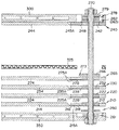
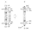
図1は本発明にかかる組電池の外観を示す斜視図、図2は図1に示した組電池の主要な構成要素の積層状態を示す図1A−A方向の模式的な部分断面図、図3は図2の一部拡大断面図、図4は図1に示した組電池のバスバーと通しボルトとの接続関係を示す図、図5は図1に示した組電池を構成する単電池相互間の接続状態を模式的に示す図である。
[Battery structure]
1 is a perspective view showing an external appearance of an assembled battery according to the present invention, FIG. 2 is a schematic partial cross-sectional view in the direction of FIG. 1A-A showing a stacked state of main components of the assembled battery shown in FIG. 3 is a partially enlarged cross-sectional view of FIG. 2, FIG. 4 is a diagram showing the connection relationship between the bus bar and through bolts of the assembled battery shown in FIG. 1, and FIG. It is a figure which shows typically the connection state between.
図1に示すとおり、本願発明にかかる組電池100は、板形状のフレームがその厚み方向に複数個積層されてなる電池ユニット200を、保持手段として機能するヒートシンク300、350でその積層方向の両面から挟んで加圧し一体的に保持したものである。
As shown in FIG. 1, an assembled
図示されていないフレームは4個の扁平状の単電池を並列に配置するため4箇所の保持部を有している。組電池100はフレームが24枚積層され、積層方向6枚おきに中間ヒートシンク325が介挿される。したがって、組電池100は4個並列に配置された単電池がそれぞれ24個ずつ積層されており、合計96個の単電池を有している。
The frame (not shown) has four holding portions for arranging four flat cells in parallel. In the assembled
ヒートシンク300および350は両ヒートシンクを連結する6個の加圧ユニットをナット310A〜310Fで取り付けることによって固定する。加圧ユニットは引っ張りコイルばねの両端にナット310A〜310Fで固定されるシャフトを取り付けたものであり、これをヒートシンク300および350間に取り付けることによって電池ユニット200を構成するすべての単電池に対して積層方向に適切な面圧を与えている。
The heat sinks 300 and 350 are fixed by attaching six pressure units connecting the heat sinks with nuts 310A to 310F. The pressure unit has shafts fixed by nuts 310 </ b> A to 310 </ b> F attached to both ends of a tension coil spring, and is attached between the
組電池100の積層構造は図2および図3に示すとおりである。なお、これらの図は発明の理解を容易にするために簡略化して記載してある。これらの図には、ヒートシンク350と中間ヒートシンク325との間には4枚のフレームしか設けられていないが、実際には6枚のフレームが設けられている。
The laminated structure of the assembled
小モジュールを構成することになるフレーム210(絶縁ワッシャ埋め込みフレーム)の一端部には絶縁性の部材である絶縁ワッシャ212が埋め込まれ、フレーム210の周囲には単電池214の周縁部216を支持する周縁支持部218が形成されている。フレーム210において周縁支持部218によって囲まれているフレーム210の中央部分は開口され、積層方向に隣接する要素(ヒートシンク350および単電池224)と単電池214の外装面とが直接接触するようになっている。フレーム210の他端部には単電池214の電極タブ215Bを、積層方向に隣接する単電池224の電極タブ225Bと超音波溶接するための開口部217Aが設けられている。単電池214の電極タブ215Aは絶縁ワッシャ212および後述するバスバー260と接触する。なお、絶縁ワッシャ212の厚みは、フレーム210の厚みよりも厚く単電池214の厚みよりも薄くしてある。つまり、絶縁ワッシャ212の厚みはフレーム210と単電池214の厚みの間の厚みとなるようにしている。組電池100を構成するすべての絶縁ワッシャ埋め込みフレームはこのような厚み関係の絶縁ワッシャを使用している。
An
フレーム220(導通ワッシャ埋め込みフレーム)の一端部には導電性の部材である導通ワッシャ222が埋め込まれ、フレーム220の周囲にはフレーム210と同様の周縁支持部228が形成され、また、周縁支持部228によって囲まれているフレーム220の中央部分は開口されている。フレーム220の他端部にはフレーム210と同様の開口部217Bが設けられている。単電池224の一方の電極タブ225Aは導通ワッシャ222と接触し、この導通ワッシャ222を介して単電池234の電極タブ235Aと接続される。なお、導通ワッシャ222の厚みは、フレーム220の厚みよりも厚く単電池224の厚みよりも薄くしてある。つまり、導通ワッシャ222の厚みはフレーム220と単電池224の厚みの間の厚みとなるようにしている。このような厚み関係とすれば、単電池224に所望の面圧を与えつつ電極タブ225Aと導通ワッシャ222とを接触させることができるからである。組電池100を構成するすべての導通ワッシャ埋め込みフレームはこのような厚み関係の導通ワッシャを使用している。
A
フレーム210に位置決め支持されている単電池214の電極タブ215Bとフレーム220に位置決め支持されている単電池224の電極タブ225Bは、それぞれのフレームに設けられている開口部217A、217Bの両側から図示しない冶具で加圧され超音波溶接が施される。
The
フレーム230(絶縁ワッシャ埋め込みフレーム)の一端部には絶縁ワッシャ232が埋め込まれ、フレーム230の周囲にはフレーム210と同様の周縁支持部238が形成され、また、周縁支持部238によって囲まれているフレーム230の中央部分は開口されている。フレーム230の他端部にはフレーム210と同様の開口部217Cが設けられている。単電池234の一方の電極タブ235Aは絶縁ワッシャ232および導通ワッシャ222と接触する。フレーム220とフレーム230を積層すると、開口部217Cの存在によって、単電池234の電極タブ235Bが溶接済みの下側の電極タブ215B、225Bと接触してしまうので、電極タブ225Bの上側には絶縁テープ250Aが貼り付けてある。
An insulating
フレーム265(導通ワッシャ埋め込みフレーム)の一端部には導通ワッシャ266が埋め込まれ、このフレーム265の上に積層される中間ヒートシンク325の載置部273が形成されている。また、フレーム265の周囲にはフレーム210と同様の周縁支持部278が形成され、また、周縁支持部278によって囲まれているフレーム265の中央部分は開口されている。フレーム265の他端部にはフレーム210と同様の開口部277Dが設けられている。単電池274の一方の電極タブ275Aは導通ワッシャ266と接触している。なお、導通ワッシャ266の厚みは、絶縁ワッシャまたは導通ワッシャの厚み(絶縁ワッシャの厚み=導通ワッシャの厚み)に中間ヒートシンク325の厚みを加えた厚みに等しくしている。
A
図2および図3ではヒートシンク350と中間ヒートシンク325との間に4枚のフレームしか介在されていないが、実際には、ヒートシンク350と中間ヒートシンク325との間に、下側の層から(絶縁ワッシャ埋め込みフレーム)−(導通ワッシャ埋め込みフレーム)−(絶縁ワッシャ埋め込みフレーム)−(導通ワッシャ埋め込みフレーム)−(絶縁ワッシャ埋め込みフレーム)−(導通ワッシャ埋め込みフレーム)という順番でフレームが6枚積層される。
2 and 3, only four frames are interposed between the
フレーム265の載置部273には中間ヒートシンク325が載せられる。中間ヒートシンク325と導通ワッシャ266とはフレーム265によって絶縁されている。
An
中間ヒートシンク325の上側にはさらに(6枚のフレーム)−(中間ヒートシンク)−(6枚のフレーム)−(中間ヒートシンク)−(6枚のフレーム)−ヒートシンク300がこの順番で積層される。ヒートシンク300の直下のフレーム240は、フレーム220と同様の構成となっている。つまり、フレーム240には導通ワッシャ242が埋め込まれ、フレーム210と同様の周縁支持部248が形成され、また、周縁支持部248によって囲まれているフレーム240の中央部分は開口されている。フレーム240の他端部にはフレーム210と同様の開口部217Eが設けられている。単電池244の一方の電極タブ245Aは導通ワッシャ242と接触している。図示はしていないが、単電池244の電極タブ245Bはその下側に位置する単電池の電極タブと超音波溶接されている。電極タブ245Bの上側にはヒートシンク300との絶縁を図るため絶縁テープ250Bが貼り付けられている。
On the upper side of the
積層されたすべてのフレームは通しボルト270とボルト271とによって固定される。ナット271と導通ワッシャ242との間には絶縁ワッシャ278、ワッシャ279が介在しているが、絶縁ワッシャ278はバスバー262の絶縁用として、ワッシャ279は絶縁ワッシャ278がセラミック製のためその破損防止用として、それぞれ用いられる。
All the laminated frames are fixed by through
ヒートシンク350には積層されている単電池をその単電池の配列方向に隣接する単電池と電気的に接続するためのバスバー260が設けられている。バスバー260は絶縁ワッシャ261によってヒートシンク350と絶縁されている。バスバー260にはその周囲を絶縁処理した通しボルト270が機械的に接続されている。組電池100に存在しているバスバー260、262、264と通しボルト270、275、280、285とは図4に示すように連結されている。通しボルト270、275、280、285はヒートシンク350の底面から立設され、通しボルト270、275、280、285は積層されている単電池同士をバスバー260、262、264によって直列に接続する。
The
図2および図3において、これらの図が図4のA−A断面を表しているとするならば、符番262は電力端子450Aに繋がる部材263を、これらの図が図4のB−B断面を表しているとするならば、符番262はバスバーをそれぞれ表すことになる。
2 and 3, if these figures represent the AA cross section of FIG. 4, the
ヒートシンク300と350が電池ユニット200を介在させた状態でボルトおよびナット310A〜310Fによって固定され、4本の通しボルトが4個の連結端子で締め付けられると、組電池100を構成する単電池は図5に示すように直列に接続される。
When the
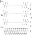
組電池100は、24個の単電池が積層された4列の単電池積層体を有しているが、図5に示すように、各単電池積層体400、410、420、430は、単電池がその積層方向にすべて直列に接続されている。すなわち、単電池積層体400の左側の単電池同士の接続(図中の×印部分)は超音波溶接によって行われ、単電池同士の絶縁(図中の四角印部分)は絶縁テープ(たとえば図2の250A、250B)によって行われている。一方、単電池積層体400の右側の単電池同士の接続(図中の○印部分)は導通ワッシャ(たとえば図2の222、266など)によって行われ、単電池同士の絶縁(図示三角印部分)は絶縁ワッシャによって行われている。したがって、組電池100が組み上がると、単電池積層体400を構成するすべての単電池が直列に接続される。他の単電池積層体410、420、430も同一の構造によりすべての単電池が直列に接続される。
The assembled
各単電池積層体400、410、420、430は、さらにヒートシンク(図2の300、350)に取り付けられたバスバー260、262、264(図4参照)によって直列に接続される。このように、組電池100を構成するすべての単電池は直列に接続される。このような接続方法を採用すると、電力端子450A、450Bの接続部を一方向(ヒートシンク300の上側)のみにすることができるので、組電池設置後の電力配線が行いやすくなり生産性が向上する。
Each
組電池100の全体の構造は以上のとおりである。次に、組電池を構成する主要な構成要素について詳細に説明する。
The overall structure of the assembled
(単電池)
本実施の形態で用いる単電池214は、図6に示すような矩形状の扁平型積層二次電池であり、少なくとも正極板と負極板を順に積層した積層型の発電要素を内部に備えており、たとえば、特開2003−059486号公報に開示されているような構造を持つものである。単電池214はその外装材としてラミネートフィルムが用いられ、内蔵されている発電要素は単電池214の周縁部のラミネートフィルムが熱融着接合されることで封止される。単電池214の長手方向両側面からは電極タブ215A、215Bが引き出されている。電極タブ215Aは+の電極タブであり、たとえば厚さ0.2mm程度のアルミニウム薄板で構成されている。一方、電極タブ215Bは−の電極タブであり、たとえば厚さ0.2mm程度の銅の薄板で構成されている。両電極タブ215A、215Bには通しボルト(図2の270)を挿入するための挿入孔272A、272Bが開口されている。なお、熱融着接合されている単電池214の周縁部216はフレームに形成されている保持部で位置決め保持される。単電池の積層方向は、この発電要素を構成する正極板と負極板の積層方向と同一の方向である。
(Single cell)
The
本実施の形態では図6のように対抗する2辺に別々の極性の電極タブが取り付けられているタイプの単電池を用いて組電池100を構成しているが、特開2003−059486号公報に開示されているように、1辺のみに別々の極性の電極タブが取り付けられているタイプの単電池を用いて組電池100を構成しても良い。ただ、このタイプの単電池を用いた場合には、フレームの構造や単電池同士の接続方法は本実施の形態とは大きく異なる。また、本実施の形態では、1つの扁平型電池を単電池としているが、直列接続された複数の電池、または並列接続された複数の電池、直列と並列の接続を交えて接続された複数の電池をそれぞれ単電池としてフレームに保持させても良い。
In the present embodiment, the assembled
(フレーム)
本実施の形態で用いるフレームは、図7Aに示すような絶縁ワッシャ埋め込みフレーム210、図7Bに示すような導通ワッシャ埋め込みフレーム220の2種類である。
(flame)
There are two types of frames used in this embodiment: an insulating washer embedded
絶縁ワッシャ埋め込みフレーム210は、その一端部210Aに絶縁ワッシャ212が埋め込まれている。絶縁ワッシャ212の厚みはフレーム210の厚みよりも若干厚く単電池の厚みよりも薄くなっている。
The insulating washer embedded
導通ワッシャ埋め込みフレーム220は、その一端部220Aに導通ワッシャ222が埋め込まれている。導通ワッシャ222の厚みは、図2、3に符番265で示した中間ヒートシンク325直下のフレームにおける導通ワッシャ266を除いて、絶縁ワッシャと同様、フレーム220の厚みよりも若干厚く単電池の厚みよりも薄くなっている。導通ワッシャは、フレームに保持されている単電池の一方の電極タブを積層方向に隣接する他のフレームに保持されている単電池の一方の電極タブと電気的に接続する第1接続手段としての機能を備えている。
The conductive washer embedded
上記の各フレーム210、220は、図7に示すように、1の平面上に配列される4個の単電池を位置決め保持する保持部を備えている。すなわち、単電池214(図6参照)の周縁部216の少なくとも1部を支持する周縁支持部218、228と、単電池214を位置決めする位置決め部とを備えている。なお、位置決め部とは、周縁支持部218、228の周囲に形成され、単電池214の周縁端がはまり込むように形取られている部分である。フレーム210、220の2隅には後述するロケートピン(図10の符番510、520)を挿入する図示しないロケートピン挿入孔が開口されている。
As shown in FIG. 7, each of the
単電池はフレームの位置決め部によってその位置が固定され、周縁支持部でその周縁部が支持される。単電池の周縁部とフレームの周縁支持部は両面テープで仮止めされる。したがって、製造段階において単電池をフレームに載置した状態で容易に搬送することができる。 The position of the cell is fixed by the positioning part of the frame, and the peripheral part is supported by the peripheral support part. The peripheral part of the cell and the peripheral support part of the frame are temporarily fixed with a double-sided tape. Therefore, the unit cell can be easily transported in a state of being placed on the frame in the manufacturing stage.
各フレームには、その導通または絶縁ワッシャが取り付けられている側の端部に図8に示すような電圧検出用端子500が取り付けられている。電圧検出用端子500は各単電池の電圧を検出するために設けられている端子であり、各単電池の電極タブと溶接によって接続される。図1に示したようにフレームが積層されると、図9に示すように、電圧検出用端子500はフレームの積層方向に規則正しい間隔で1列ずつ配列されることになる。すべての電圧検出用端子500には図示しないコネクタが取り付けられ、個々の単電池の電圧が充放電を制御する制御装置に提供される。このように、フレームに電圧検出用端子500が一体化されるようにすると、電圧検出用端子500への配線作業が効率化され作業性が向上する。
A
(ヒートシンク)
本実施の形態で用いるヒートシンクは、図1に示したとおり、最上段に位置されるヒートシンク300、積層されているフレーム間に少なくとも1以上介挿される中間ヒートシンク325、最下段に位置されるヒートシンク350の3種類である。
(heatsink)
As shown in FIG. 1, the heat sink used in the present embodiment includes a
最下段のヒートシンク350は、図10に示すように、積層されるフレームを位置決めするためのロケートピン510、520を備えている。もちろんフレームにはこれらのロケートピン510、520が挿入されるロケートピン挿入孔(図示せず)が開口されている。ヒートシンク350にフレームを積層する場合には、フレームのロケートピン挿入孔をこれらのロケートピン510、520に挿入しフレームの位置決めを行う。また、ヒートシンク350の一端部には隣り合う単電池積層体同士、たとえば単電池積層体400と410(図5参照)を電気的に直列接続するためのバスバー260、264を埋め込むバスバー埋め込み溝360、370が設けられている。バスバー埋め込み溝360、370には通しボルト270、275、280、285(図4参照)をヒートシンク350の底面から立設するための通しボルト挿入孔362、364、372、374が開口されている。さらに、ヒートシンク350には、電池ユニット200に適切な面圧を付与するとともに電池ユニット200をヒートシンク300、350と一体的に保持するための保持手段としての機能を有する加圧ユニットの取り付け孔380〜385が設けられている。
As shown in FIG. 10, the
これらの取り付け孔380〜385には図11に示すように、6個の加圧ユニット530〜535が取り付けられる。加圧ユニット530〜535は、ヒートシンク300と350で電池ユニット200を挟み込むときに、電池ユニット200に付与する面圧を容易に微調整できるようにするものである。ヒートシンク300、350の材質としては銅、アルミニウム、マグネシウムなどが適切であるが、放熱性や軽量化を考慮するとアルミニウムが最適である。ヒートシンク350は、放熱効率を向上させるためその長手方向に貫通する通気口352が形成されている。
As shown in FIG. 11, six
加圧ユニット530〜535は具体的には次のような構造になっている。図12は加圧ユニットの具体的な構成図、図13は加圧ユニットの動作説明図である。特に、図12Aは加圧ユニットの全体構成を示す図、図12Bはバネ保持部の構成を示す図であり、図13Aは加圧ユニットの初期状態を示す図、図13Bは加圧ユニットをヒートシンク間に取り付けた様子を示す図である。
Specifically, the pressurizing
加圧ユニット530は、引っ張りコイルバネ542(弾性体)と、引っ張りコイルバネ542の両端を保持するバネ保持部543とからなる。
The
引っ張りコイルバネ542は、引き延ばされた状態でヒートシンク300、350(図1参照)間に取り付けられる。これによって、引っ張りコイルバネ542は収縮しようと作用し、ヒートシンク300、350を相互に接近させる方向の引っ張り力を発生する。
The
バネ保持部543は、本体部544と、引っ張りコイルバネ542のピッチP1よりも大きなピッチP2でねじ山が形成された螺合部545と、螺合部545から引っ張りコイルバネ542の中心に向かって伸びる突合せ部546と、本体544から伸びてヒートシンク300、350に挿通される挿通部547とを含む。
The
本体部544は、引っ張りコイルバネ542より大きな径を有し、引っ張りコイルバネ542が外れないように、これに当接する。また、本体部544は、加圧ユニット530を組電池に取り付けたときに、ヒートシンク300、350と当接する。
The
螺合部545は、図示のとおり、引っ張りコイルバネ542の端部にねじ込まれて、引っ張りコイルバネ542の内側と螺合し、これを固定する。螺合部545は、図12Bに示すように、表面にピッチP2のねじ山が形成されている。螺合部545のピッチP2は、引っ張りコイルバネ542のピッチP1より大きい。したがって、螺合部545を図12B中矢印の方向にねじ込むことができる。螺合部545をねじ込むことによって、突合せ部546が、引っ張りコイルバネ542の中央に向かって進行する。
As shown in the figure, the screwing
引っ張りコイルバネ542の両端から螺合部545をねじ込んで行くと、図12Aに示すように、両側から進行してきた突合せ部546が突き当たる。この状態で、引っ張りコイルバネ542は自然長より伸ばされ、加圧ユニット530の初期状態として、初期張力が与えられている。
When the screwing
挿通部547は、先端にナット541と締結可能なねじ山が形成されている。挿通部547の頭には、後述する回り止め用のスリット548が設けられている。スリット548に、マイナスドライバー等を挿すことによって、バネ保持部543を容易に回り止めできる。
The
以上のような、加圧ユニット530を、ヒートシンク300,350間に配置すると、図13Aに示すようになる。
When the pressurizing
ここで、挿通部547は、ヒートシンク300取り付け孔に挿通されている。この状態で、一方のバネ保持部543を回り止めしながら、他方のバネ保持部543の挿通部547をナット541で締結する。すると、バネ保持部543がナット541側に引き寄せられる。これを両方のバネ保持部543で行うと、図13Bに示すように、バネ保持部543が引っ張りコイルバネ542を保持した状態で相対的に引き離され、引っ張りコイルバネ542がヒートシンク300、350間に引き伸ばされた状態で保持される。
Here, the
このように、ヒートシンク300、350間の幅に合わせて、引っ張りコイルバネ542を引き伸ばすので、ナット541の締め付けトルクに関わらず、引っ張りコイルバネ542による収縮する方向の弾性力が得られる。該弾性力が電池ユニット200を構成する単電池への加圧力となる。
In this manner, the
中間ヒートシンク325は、図14に示すように、ロケートピン510、520を貫通するロケートピン貫通孔330、332、加圧ユニット530〜535を貫通させる加圧ユニット貫通孔335〜340、通しボルトを貫通させる通しボルト貫通口341〜344が開口されている。
As shown in FIG. 14, the
中間ヒートシンク325はヒートシンク350に取り付けられているロケートピン510、520をロケートピン挿入孔330、332に挿入することで位置決めされる。中間ヒートシンク325は、電池ユニット200に等間隔で3枚介挿される。中間ヒートシンク325の材質としてはヒートシンク350と同一のものでも良いが軽量化を考慮して熱伝達性の良い樹脂を用いても良い。
The
最上段のヒートシンク300は、図15に示すように、ロケートピン510、520を挿入するロケートピン挿入孔312、314、加圧ユニット530〜535の上に取り付けられているボルトを貫通させそれをナット310A〜310Fで固定するためのボルト挿入孔315〜320、通しボルトを貫通させる通しボルト貫通口321、322、電力端子450A、450B(図4参照)を取り付けるための電力端子取り付け孔323、324が開口されている。ヒートシンク300はロケートピン挿入孔312、314にロケートピン510、520を挿入することで位置決めされる。ヒートシンク300を位置決めするときに加圧ユニット530〜535の上に取り付けられているボルトをボルト挿入孔315〜320に挿入し、ナット310A〜310Fでヒートシンク300を固定する。この固定によってヒートシンク300と350が電池ユニット200と一体化される。通しボルト貫通口321、322には図示上から下方向に向けて通しボルトが挿入される。この通しボルトにはバスバー262(図4参照)が取り付けられる。電力端子取り付け孔323、324には電力端子450A、450Bが取り付けられ、これらの電力端子が充電装置または動力源のモータに接続される。
As shown in FIG. 15, the
ヒートシンク300と350は、電池ユニット200をその積層方向の両面から加圧して一体的に保持する保持手段として機能し、この保持手段は、電池ユニット200を構成するすべての単電池に積層方向の面圧を付与する加圧手段としての機能と、電池ユニット200から生じる熱を放散する冷却手段としての機能とを備えている。また、ヒートシンク300と350は、電池ユニット200を構成する1つの単電池積層体(たとえば図5の電池積層体400)を別の単電池積層体(たとえば図5の電池積層体410)に電気的に接続する第3接続手段としてのバスバー(たとえば図4の260)を取り付ける機能を備えている。
The heat sinks 300 and 350 function as holding means that pressurizes and integrally holds the
[組電池の製造手順]
次に、本実施の形態にかかる組電池の製造手順を図面に基づいて詳細に説明する。本発明にかかる組電池は[小モジュール形成段階]と[電池ユニット形成段階]を経て製造される。
[Battery manufacturing procedure]
Next, the manufacturing procedure of the assembled battery according to the present embodiment will be described in detail with reference to the drawings. The assembled battery according to the present invention is manufactured through a [small module forming step] and a [battery unit forming step].
(小モジュール形成段階)
まず、図16に示すように、電池ユニット200の最下層に位置されることになる板形状を成すフレーム210に4個の単電池214A〜214Dを載置する。単電池を載置するときには、各単電池の周縁部216に厚みの非常に薄い両面テープを貼り付け、周縁部216をフレーム210の周縁支持部218に載置させてその位置決め部にはめ込むようにする。これによって4個の単電池はフレームに仮止めされ、製造現場での搬送が可能になる。4個の単電池がフレームに載置された状態は図17に示すとおりであるが、単電池をフレームに配列させるときには、その電極タブ215の極性が図16、図17に示すように、単電池の配列方向に正負交互となるようにする。つまり、単電池の極性が+−交互に並ぶように単電池の向きを変えながら配列する。
(Small module formation stage)
First, as shown in FIG. 16, four
次に、図17に示すように、フレーム210に配列された単電池214A〜214Dの片側の電極タブ215を電圧検出用端子500に超音波溶接によって接合する。片側の電極タブとは、フレーム210の導通ワッシャまたは絶縁ワッシャが埋め込まれている側に位置されている電極タブである。したがって、この段階において超音波溶接で接合する箇所は図17に示すようにフレームごとに4箇所(図示手前側の電極タブ215と電圧検出用端子500)である。
Next, as shown in FIG. 17, the
以上の単電池の配列、電極タブと電圧検出用端子との接合を、電池ユニット200を構成することになる24枚のフレームに対して行う。なお、単電池を配列するときには図18に示すようにその極性が配列方向に正負交互となるようにするだけではなく、フレームの積層方向にもその極性が正負交互となるように注意する。たとえば、最下層位置されるフレームに載置する単電池の極性が図17に示すように手前左端から「+」、「−」、「+」、「−」と並んでいるのであれば、そのフレームの上に積層されるフレームに載置する単電池の極性は手前左端から「−」、「+」、「−」、「+」となるように配列する。単電池をこのように配列しないと、最終的に図5に示すような直列回路を構成することができないからである。
The arrangement of the unit cells and the joining of the electrode tab and the voltage detection terminal are performed on 24 frames constituting the
(電池ユニット形成段階)
次に、絶縁ワッシャ212が埋め込まれているフレーム210に導通ワッシャが埋め込まれているフレーム220を図19に示すように重ねる。重ねるときには、導通ワッシャと絶縁ワッシャが取り付けられている側を同一方向にして重ねる。フレームの導通ワッシャと絶縁ワッシャが取り付けられていない側の端部には図16に示すように開口部217Aが形成されている。フレーム210の下側およびフレーム220の上側の開口部217Aに超音波溶接装置の冶具を挿入し、フレーム210とフレーム220に載置されている単電池の電極タブをその冶具で挟んで超音波溶接を行う。この超音波溶接は図19に示すように4組の単電池の片側の電極タブ215、225に対して行う。
(Battery unit formation stage)
Next, the
電極タブ同士の接合に超音波溶接を用いるのは次の2つの理由からである。超音波溶接は、接合される部分に高周波振動を与えることによって金属の原子を拡散させ、再結晶させることによって機械的な接合を行うため、同種、異種の金属の重ね溶接に対して非常に効果的である。本実施の形態で用いている単電池は、その一方の電極タブがアルミニウムの薄板であり、他方の電極タブが銅の薄板である。また、バスバーおよび電圧検出用端子は銅製である。したがって、電極タブ同士の接合、電極タブと電圧検出用端子との接合は異種金属同士の接合になる。このために超音波溶接を用いている。これがまず1つ目の理由である。次に、超音波溶接は、接合時に高い温度に達することなく、接合面の最高温度は融点の35〜50%程度に抑えることができるため、高温溶接を行ったときに生じる母材の溶融やもろい鋳造組織が形成されることはない。本実施の形態で用いている単電池は、外装がラミネート材であり電極タブをあまり高い温度に上げることができないため、単電池を高温状態にさらすことなく、非常に薄い金属で形成されている電極タブを接合するのには超音波調節が最適である。これが2つ目の理由である。 The ultrasonic welding is used for joining the electrode tabs for the following two reasons. Ultrasonic welding is very effective for lap welding of the same or different kinds of metals because it performs mechanical joining by diffusing and recrystallizing metal atoms by applying high-frequency vibration to the parts to be joined. Is. In the unit cell used in the present embodiment, one electrode tab is an aluminum thin plate, and the other electrode tab is a copper thin plate. The bus bar and the voltage detection terminal are made of copper. Therefore, the bonding between the electrode tabs and the bonding between the electrode tab and the voltage detection terminal are bonding between different metals. For this purpose, ultrasonic welding is used. This is the first reason. Next, in ultrasonic welding, the maximum temperature of the joint surface can be suppressed to about 35 to 50% of the melting point without reaching a high temperature at the time of joining. A brittle cast structure is not formed. The unit cell used in the present embodiment is made of a very thin metal without exposing the unit cell to a high temperature state because the exterior is a laminate material and the electrode tab cannot be raised to a very high temperature. Ultrasonic adjustment is optimal for joining electrode tabs. This is the second reason.
この溶接によって図17、図18に示すように電極タブ215、225が電圧検出用端子500とともに接合される。ここまでの作業によって絶縁ワッシャ212が埋め込まれているフレーム210と導通ワッシャが埋め込まれているフレーム220を1組とするフレームユニットが形成される。この溶接は、電池ユニット200を構成することになる12組のフレームユニットに対して行う。溶接作業が終了すると、フレームユニットが積層されて行くときに、フレームユニット間で電気的な絶縁を図るため、図17に示すように電極タブ215の外側の面に絶縁テープ250Aを貼り付ける。
By this welding, the
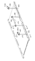
次に、図20に示すように、ヒートシンク350にロケートピン510、520を立て、加圧ユニット530〜535を取り付け、バスバー260、264を設置して通しボルト270、275、280、285を取り付ける。そして、上記のフレームユニット550に設けられているそれぞれの孔に図に示すようにロケートピン510、520、加圧ユニット530〜535、通しボルト270、275、280、285を通し、フレームユニット550をヒートシンク350上に載せる。フレームユニット550は導通ワッシャが取り付けられているフレームを上側にして載置する。フレームに載置されている各単電池は、バスバー260または264と直接接触し電気的に接続される。なお、バスバー260、264はヒートシンク350との間では絶縁ワッシャによって絶縁されている。
Next, as shown in FIG. 20, locate
上記のようにしてフレームユニット550を3組、導通ワッシャが取り付けられているフレームを上側にして図21のように積層する。3組のフレームユニットが積層されると6個の単電池が積層されることになる。フレームは単電池を支持する周縁部以外が開口されているので、積層方向に積み重ねられる単電池の外装面同士は直接接触する。3組のフレームユニットの上には図に示すように中間ヒートシンク325が積み重ねられる。したがって、6個の単電池がヒートシンク350と中間ヒートシンク325に挟まれる。単電池の外装面同士は直接接触しているので、単電池の内部で発生した熱はヒートシンク350および中間ヒートシンク325に効率的に伝達されて放熱される。もちろん熱の一部はフレームから間接的にこれらのヒートシンクに伝えられる。放熱性を考慮すれば、フレームの材料は熱伝達特性の良いものを使用することが望ましい。
As described above, three sets of the
さらに、中間ヒートシンク325の上に(3組のフレームユニット)−(中間ヒートシンク325)−(3組のフレームユニット)−(中間ヒートシンク325)−(3組のフレームユニット)を積み重ね、最後にヒートシンク300を重ねて、ナット310A〜310F(図1参照)でヒートシンク300を仮止めし、通しボルト270、275、280、285をナットで仮止めする。
Further, (three sets of frame units)-(intermediate heat sink 325)-(three sets of frame units)-(intermediate heat sink 325)-(three sets of frame units) are stacked on the
なお、本実施の形態においては、導通ワッシャの厚みを単電池の厚み以下としているため、単にフレームユニットを積層しただけでは、フレームユニット間の通電は行われず、作業者は電圧を考慮することなく作業ができる。なお、電圧を考慮することなく作業を容易に行うためには、その電圧を40V以下とすることが望ましい。また、1枚のフレームユニットが積層される度に通しボルト(図5の270)に紙製の絶縁ワッシャを挿入して各フレームユニットを確実に絶縁することが好ましい。これにより組電池としては電力端子450A、450B間には高電圧が得られる。このため作業者が確実に高電圧にさらされずに済む。したがって、以上のように通しボルト270、275、280、285をナットで仮止めした状態では、すべての単電池が電気的には接続されていない状態にある。
In the present embodiment, since the thickness of the conductive washer is equal to or less than the thickness of the unit cell, the current between the frame units is not simply energized by simply stacking the frame units, and the operator does not consider the voltage. I can work. In order to easily perform the work without considering the voltage, it is desirable that the voltage be 40 V or less. Further, it is preferable that a paper insulating washer is inserted into a through bolt (270 in FIG. 5) each time one frame unit is stacked, so that each frame unit is reliably insulated. As a result, a high voltage is obtained between the
以上のようにして組電池100を組み立て、紙製の絶縁ワッシャを挿入した場合にはフレームユニット間に介在されている紙製の絶縁ワッシャを取り除き、最後に仮止め状態のすべてのナットを締め込むと、各単電池に面圧が加わり、電極タブと導通ワッシャが接触して組電池100を構成するすべての単電池は、図5に示したように電力端子450A、450B間で直列に接続されることになり電力端子450A、450B間に高電圧が得られる。
When the assembled
以上のように、本実施の形態では、単電池の一方の電極タブを超音波溶接し、他方の電極タブを通しボルトで固定したが、両側の電極タブを通しボルトで固定するようにしても良い。両側の電極タブを通しボルトで固定する場合には、通しボルトに導通ワッシャと絶縁ワッシャとを交互に入れて隣接する電極タブ同士を導通または絶縁させる。この場合には、電圧検出用端子はその端子が接続された導通ワッシャを通しボルトに挿入することによって設置するようにしても良い。また、両方の電極タブを超音波溶接するようにしても良い。この場合、フレームを積層しながら超音波溶接をする必要があるので、超音波溶接の冶具が狭い隙間内でも設置することができるように、単電池の電極タブの引き出し位置を単電池の積層位置によって変えると良い。たとえば、最下層に配置されるフレームユニットに載置する単電池はその電極タブが左側にオフセットされているものを配置し、その上に積層されるフレームユニットに載置する単電池はその電極タブが通常通り中央から引き出されているものを配置し、さらにその上に積層されるフレームユニットに載置する単電池はその電極タブが右側にオフセットされているものを配置する。このようにすれば、フレームユニットを積層した状態でも超音波溶接の冶具の設置スペースが確保しやすくなる。 As described above, in the present embodiment, one electrode tab of the unit cell is ultrasonically welded and the other electrode tab is fixed with a through bolt, but the electrode tabs on both sides may be fixed with a through bolt. good. When the electrode tabs on both sides are fixed with through bolts, conductive washers and insulating washers are alternately inserted into the through bolts to conduct or insulate adjacent electrode tabs. In this case, the voltage detection terminal may be installed by inserting a conduction washer to which the terminal is connected into a bolt. Further, both electrode tabs may be ultrasonically welded. In this case, it is necessary to perform ultrasonic welding while laminating the frames, so the position where the electrode tabs of the unit cells are pulled out is positioned so that the ultrasonic welding jig can be installed even in a narrow gap. It is good to change by. For example, the unit cell placed on the frame unit arranged in the lowermost layer is arranged such that the electrode tab is offset to the left side, and the unit cell placed on the frame unit laminated thereon is arranged on the electrode tab Is arranged as usual, and the unit cell placed on the frame unit stacked thereon is arranged such that its electrode tab is offset to the right side. If it does in this way, it will become easy to ensure the installation space of the jig of ultrasonic welding even in the state where the frame unit was laminated.
[実施の形態2]
実施の形態2に示す組電池は、実施の形態1とは単電池同士の接続方法が異なっている。具体的には、フレームに配列された単電池をフレーム内で直列に接続して小モジュールを形成し、さらにこれらの単電池を積層方向に隣接するフレーム間で直列に接続して電池ユニット200を形成し、電池ユニット200に含まれる単電池をすべて直列に接続したものである。
[Embodiment 2]
The assembled battery shown in the second embodiment is different from the first embodiment in the connection method between the single cells. Specifically, the single cells arranged in the frame are connected in series in the frame to form a small module, and further, these single cells are connected in series between the frames adjacent in the stacking direction to form the
本実施の形態では、フレームに配列されている単電池を並列に接続するため、図22、図23に示すように構成されたフレーム600を用いている。図22はフレーム600を載置される単電池605〜608とともに示した斜視図であり、図23はフレーム600を載置された単電池605〜608とともに模式的に示した平面図である。
In the present embodiment, a
これらの図に示されているように、フレーム600は、その一端部610Aの両側にL字形状のバスバー620A、620Bを有し、その中央部分にI字形状のバスバー620Cを有している。さらにフレーム600の他端側610BにI字形状のバスバー620D、620Eを有している。なお図示はしないが、実施の形態1で説明したフレームと同様に、各フレームは、1の平面上に配列される4個の単電池を保持する保持部を備えている。すなわち、単電池の周縁部の少なくとも1部を支持する周縁支持部と、単電池を位置決めする位置決め部とを備えている。なお、位置決め部とは、周縁支持部の周囲に形成され、単電池の周縁端がはまり込むように形取られている部分である。単電池はフレームの位置決め部によってその位置が固定され、周縁支持部でその周縁部が支持される。単電池の周縁部とフレームの周縁支持部は両面テープで仮止めされる。したがって、製造段階において単電池をフレームに載置した状態で容易に搬送することができる。
As shown in these drawings, the
フレーム600に単電池605〜608を載置させると、単電池605の電極タブ605Aはバスバー620Aに、その電極タブ605Bはバスバー620Dに接触する。単電池606の電極タブ606Aはバスバー620Cに、その電極タブ606Bはバスバー620Dに接触する。単電池607の電極タブ607Aはバスバー620Cに、その電極タブ607Bはバスバー620Eに接触する。単電池608の電極タブ608Aはバスバー620Bに、その電極タブ608Bはバスバー620Eに接触する。
When the
フレーム600には単電池の極性の配列が図23に示すように+−交互となるように単電池を載置する。このように単電池を配列すると1枚のフレームに載置したすべての単電池が直列に接続される。バスバー620A〜620Eは、フレームに保持されている単電池の一方の電極タブを同一のフレームに保持されている他の単電池の一方の電極タブと電気的に接続する第2接続手段として機能する。
The cells are placed on the
図24に示すように、フレーム600上に載置された単電池605〜608の各電極タブ605A、605B、606A、606B、607A、607B、608A、608Bは、それぞれの電極タブが接触しているバスバー620A〜620Eと超音波溶接される。図25は、図24のフレーム600を矢視B方向(下側)から見た図であるが、フレームの一端部610Aと他端部にはバスバーと電極タブを超音波溶接によって接合するための冶具の挿入口630A〜630Hが設けられている。これらの挿入口から超音波溶接機の冶具を入れ、電極タブ側を超音波振動させて電極タブとバスバーとを接合する。
As shown in FIG. 24, the
以上のようにして単電池が接合されたフレームを実施の形態1の場合と同様ヒートシンク350上に24枚積層させて組電池を形成する。なお、フレームを積層するときには、単電池の極性がフレームの積層方向にも正負交互となるように注意する。たとえば、最下層位置されるフレームに載置する単電池の極性が図23に示すように手前左端から「+」、「−」、「+」、「−」と並んでいるのであれば、そのフレームの上に積層されるフレームに載置する単電池の極性は手前左端から「−」、「+」、「−」、「+」となるように配列する。
As in the case of the first embodiment, 24 frames are stacked on the
このように配列すれば、各フレームが有するL字形状のバスバーの極性も積層方向に正負交互に並ぶため、積層方向に隣接するバスバーを2つおきに絶縁物を介在させながら接続することによって、積層されているすべての単電池を図26に示すように直列に接続することができる。なお、本実施の形態の場合にもフレームを6枚積層するごとに中間ヒートシンクを介在させている。 If arranged in this way, the polarities of the L-shaped bus bars of each frame are also alternately arranged in the laminating direction, so by connecting every two bus bars adjacent in the laminating direction while interposing an insulator, All the unit cells stacked can be connected in series as shown in FIG. In the present embodiment, an intermediate heat sink is interposed every time six frames are stacked.
図26の最下層に示す回路は図23のフレーム600によって形成される回路である。図に示すように、同一フレームに配列されている単電池605〜608がバスバー620A〜620Eによって直列に接続される。そのフレーム600の上にはさらに別のフレームが積層されるが、フレームを重ねた状態でバスバー620Bの上側に位置されるバスバー(図中の×印部分)が超音波溶接される。また、一方のバスバー620Aは上側に位置されるバスバーと接触しないようにバスバー620Aの上側に絶縁テープ(図中の四角印部分)が貼り付けられる。図に示すように24枚のフレームを積層し、積層方向に隣接する一方のバスバーを超音波溶接し、他方のバスバーを絶縁処理すると、最終的には96個の単電池が直列に接続された直列回路が構成できる。
The circuit shown in the lowermost layer in FIG. 26 is a circuit formed by the
なお、本実施の形態ではバスバー同士の接続を超音波溶接で行うようにしたが、ボルトナットを用いて接続するようにしても良い。ただ、ボルトナットで接合した場合にはその自重でバスバーの振動が起こりやすくなるのでその振動を抑える振れ止めが必要になる。 In this embodiment, the bus bars are connected by ultrasonic welding, but may be connected using bolts and nuts. However, when joined with bolts and nuts, the bus bar tends to vibrate due to its own weight, so a steady stop is required to suppress the vibration.
[実施の形態3]
実施の形態3に示す組電池は、実施の形態1、2とは異なり、1個の単電池しか載置できないフレームを用いて形成されている。実施の形態3に示す組電池は、1個の単電池を載置したフレームを積層して小モジュールである単電池積層体を形成し、この単電池積層体を平面的に複数配置して電池ユニットを形成したものである。
[Embodiment 3]
Unlike the first and second embodiments, the assembled battery shown in the third embodiment is formed using a frame on which only one unit cell can be placed. In the assembled battery shown in Embodiment 3, a single battery stack is formed by stacking frames on which a single battery is mounted, and a plurality of the single battery stacks are arranged in a plane. A unit is formed.
図27は、本実施の形態で用いるフレーム700の構成図である。フレーム700の構造は実施の形態1で説明したフレームにおいて1つの単電池を載置する部分とほぼ同じである。すなわち、フレーム700には1個の単電池を保持する保持部が備えられている。保持部は、単電池の周縁部の少なくとも1部を支持する周縁支持部と、単電池を位置決めする位置決め部とを備えている。なお、位置決め部とは、周縁支持部の周囲に形成され、単電池の周縁端がはまり込むように形取られている部分である。
FIG. 27 is a configuration diagram of a
フレーム700の4隅にはフレーム位置決め用のロケートピンを貫通させるロケートピン貫通孔702,704,706,708が設けられている。フレーム700には電圧検出用端子720がインサート成形によって取り付けられている。フレーム700に単電池710を載置すると、単電池700の一方の電極タブ710Aが電圧検出用端子720と接触する。
Locating pin through
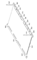
このフレーム700を図28に示すように6枚ごとに中間ヒートシンク730を介在させて合計24枚積層し、単電池積層体750を形成する。単電池積層体750を構成する単電池は、図5の単電池積層体400と同様にすべての単電池が直列に接続される。本実施の形態の場合、すべての電極タブ同士の接合は超音波溶接によって行っている。単電池積層体の最下層と最上層に位置されるフレームにはバスバー740Aおよび740Bが取り付けられている。
As shown in FIG. 28, a total of 24
以上のようにして製造した単電池積層体は図29に示されているようにヒートシンク350上に4列平面的に配置される。ヒートシンク350には各電池積層体750、760、770、780を位置決めするための16本(各単電池積層体について4本ずつ)のロケートピン745が立設されているので、各単電池積層体750、760、770、780のロケートピン貫通孔に、対応するロケートピンを挿入する。これによってすべての単電池積層体750、760、770、780がヒートシンク350上に取り付けられる。図示していないが、各単電池積層体のバスバー同士は4個の単電池積層体が直列に接続されるように接続手段で電気的に接続される。ヒートシンク350上に単電池積層体750、760、770、780が取り付けられたら最後に図1に示したようなヒートシンク300を取り付ける。これによって外観上は図1の組電池100と変わらない組電池が形成される。
The unit cell stack manufactured as described above is arranged in four rows in a plane on the
以上、第1〜第3の実施の形態で説明したように、本発明にかかる組電池は単電池間に隙間を設けることなく積層し、必要放熱量に応じた数の中間ヒートシンクを介在させ、各単電池に適切な面圧を付与しているので、小型でエネルギー密度の高い自動車搭載用電池が構成できる。さらに、隙間の存在しない堅固な構造であるので、剛性が高く耐振動性に優れている。また、その組み立てはフレームユニットを単に積み重ねてボルト締めするだけでよいので、組み立て作業性も良好である。 As described above, as described in the first to third embodiments, the assembled battery according to the present invention is laminated without providing a gap between the single cells, and a number of intermediate heat sinks according to the required heat dissipation amount are interposed, Since an appropriate surface pressure is applied to each unit cell, it is possible to configure a small vehicle-mounted battery with high energy density. Furthermore, since it has a solid structure with no gaps, it has high rigidity and excellent vibration resistance. Moreover, the assembly workability is also good because the frame units are simply stacked and bolted.
なお、本発明にかかる組電池は耐振動性、放熱性が特に優れ、また、小型軽量であるので、自動車用の電池に限られず、環境の劣悪な現場で作業を行うロボット用電源、工事現場用電源としても利用することができる。 Note that the assembled battery according to the present invention is particularly excellent in vibration resistance and heat dissipation, and is small and light. Therefore, the battery pack is not limited to a battery for automobiles, but is a power source for a robot that performs work in a poor environment, a construction site It can also be used as a power source.
本発明にかかる組電池は、自動車積載用電池として利用できるだけでなく、環境の劣悪な生産現場や工事現場で使用する電源として利用できる。 The assembled battery according to the present invention can be used not only as a vehicle-mounted battery but also as a power source used in a production site or a construction site having a poor environment.
100 組電池、
200 電池ユニット、
210、220、230 フレーム、
212、232 絶縁ワッシャ、
214、224、234、244、274 単電池、
215A、215B、225A、225B、235A、235B、245A、245B、275A、275B 電極タブ、
216 周縁部、
217A、217B、217C、217D、217E 開口部、
218、228、238、248 周縁支持部、
222、242 導通ワッシャ、
250A、250B 絶縁テープ、
260、262、264 バスバー、
270、275、280、285 通しボルト、
272A、272B 挿入孔、
300、350 ヒートシンク、
310A〜310F ナット、
325 中間ヒートシンク、
312、314、330、332 ロケートピン貫通孔、
315〜320 ボルト挿入孔、
335〜340 加圧ユニット貫通孔、
321、322 通しボルト貫通口、
323、324 電力端子取り付け孔、
341〜344 通しボルト貫通口、
352 通気口、
360、370 バスバー埋め込み溝、
362、364、372、374 通しボルト挿入孔、
380〜385 取り付け孔、
400、410、420、430 単電池積層体、
450A、450B 電力端子、
500 電圧検出用端子、
510、520 ロケートピン、
530〜535 加圧ユニット、
550 フレームユニット、
600 フレーム、
605〜608 単電池、
620A〜620E バスバー、
700 フレーム、
710 単電池、
720 電圧検出用端子、
730 中間ヒートシンク、
745 ロケートピン、
750、760、770、780 単電池積層体。
100 battery packs,
200 battery unit,
210, 220, 230 frames,
212, 232 insulation washers,
214, 224, 234, 244, 274 cells,
215A, 215B, 225A, 225B, 235A, 235B, 245A, 245B, 275A, 275B electrode tabs,
216 rim,
217A, 217B, 217C, 217D, 217E opening,
218, 228, 238, 248 peripheral support,
222, 242 conductive washers,
250A, 250B insulating tape,
260, 262, 264 bus bars,
270, 275, 280, 285 through bolts,
272A, 272B insertion hole,
300, 350 heat sink,
310A-310F nut,
325 Intermediate heat sink,
312, 314, 330, 332 locate pin through hole,
315-320 bolt insertion hole,
335-340 Pressure unit through hole,
321, 322 through bolt through hole,
323, 324 power terminal mounting hole,
341-344 through-bolt through holes,
352 vents,
360, 370 Busbar embedded groove,
362, 364, 372, 374 through bolt insertion hole,
380-385 mounting holes,
400, 410, 420, 430 cell stack,
450A, 450B power terminal,
500 Voltage detection terminal,
510, 520 locate pin,
530-535 pressure unit,
550 frame unit,
600 frames,
605-608 cells,
620A-620E bus bar,
700 frames,
710 cell,
720 voltage detection terminal,
730 intermediate heat sink,
745 locate pin,
750, 760, 770, 780 Single cell stack.
Claims (21)
当該電池ユニットは複数の小モジュールが接続されることによって形成され、
当該小モジュールは複数の扁平型単電池が接続されることによって形成され、
前記複数の扁平型単電池は1個ずつ板形状を成すフレームに保持され、当該1個の扁平型単電池を保持した板形状を成すフレームを積層することによって小モジュールが形成され、
前記フレームは、当該フレームに保持されている扁平型単電池の一方の電極タブと積層方向に隣接する他のフレームに保持されている扁平型単電池の一方の電極タブとを電気的に接続する第1接続手段を備えていることを特徴とする組電池。 An assembled battery comprising a battery unit,
The battery unit is formed by connecting a plurality of small modules,
The small module is formed by connecting a plurality of flat cells ,
The plurality of flat unit cells are held one by one in a plate-shaped frame, and a small module is formed by laminating the plate-shaped frame holding the one flat unit cell,
The frame electrically connects one electrode tab of the flat unit cell held by the frame and one electrode tab of the flat unit cell held by another frame adjacent in the stacking direction. An assembled battery comprising first connecting means .
当該電池ユニットは複数の小モジュールが接続されることによって形成され、
当該小モジュールは複数の扁平型単電池が接続されることによって形成され、
1の平面上に配列される前記複数個の扁平型単電池が板形状を成すフレームに保持されて小モジュールが形成され、前記複数個の扁平型単電池が1の平面上に配列された小モジュールを積層することによって前記電池ユニットが形成され、
前記フレームは、当該フレームに保持されている扁平型単電池の一方の電極タブと積層方向に隣接する他のフレームに保持されている扁平型単電池の一方の電極タブとを電気的に接続する第1接続手段を備えていることを特徴とする組電池。 An assembled battery comprising a battery unit,
The battery unit is formed by connecting a plurality of small modules,
The small module is formed by connecting a plurality of flat cells,
A plurality of flat unit cells arranged on one plane are held by a plate-shaped frame to form a small module, and the plurality of flat unit cells are arranged on one plane. The battery unit is formed by stacking modules,
The frame electrically connects one electrode tab of the flat unit cell held by the frame and one electrode tab of the flat unit cell held by another frame adjacent in the stacking direction. An assembled battery comprising first connecting means .
複数の小モジュールを接続して電池ユニットを形成する電池ユニット形成段階と、を含み、A battery unit forming step of connecting a plurality of small modules to form a battery unit,
前記小モジュール形成段階は、The small module forming step includes:
1個の扁平型単電池を板形状を成すフレームに保持させる段階と、Holding one flat cell in a plate-shaped frame;
当該1個の扁平型単電池を保持した板形状を成すフレームを積層する段階と、Laminating a frame having a plate shape holding the one flat unit cell;
を含むことを特徴とする組電池の製造方法。A method for producing an assembled battery, comprising:
複数の小モジュールを接続して電池ユニットを形成する電池ユニット形成段階と、を含み、
前記小モジュール形成段階においては、1の平面上に配列される複数個の扁平型単電池をフレームに保持させることによって前記小モジュールを形成し、
前記電池ユニット形成段階においては、前記複数個の扁平型単電池が1の平面上に配列された小モジュールを積層することによって前記電池ユニットを形成することを特徴とする組電池の製造方法。 A small module forming step of forming a small module by connecting a plurality of flat batteries;
A battery unit forming step of connecting a plurality of small modules to form a battery unit,
In the small module forming step, the small module is formed by holding a plurality of flat cells arranged on one plane in a frame,
Wherein in the battery unit forming step, the manufacturing method of the battery pack, characterized by forming said cell unit by laminating a small module that said plurality of flat unit cells are arranged on one plane.
前記電池ユニット形成段階においては、複数の小モジュールを接続する際に前記小モジュールを形成する扁平型単電池が相互に電気的に接続されることを特徴とする請求項16または17記載の組電池の製造方法。 In the small module formation stage, the flat type cells forming the small module are mechanically connected in small module units, but are electrically disconnected from each other.
The assembled battery according to claim 16 or 17, wherein in the battery unit formation step, flat unit cells forming the small modules are electrically connected to each other when a plurality of small modules are connected. Manufacturing method.
1の小モジュールを形成する扁平型単電池と他の小モジュールを形成する扁平型単電池との電気的な接続を溶接によって行う段階を含むことを特徴とする請求項17記載の組電池の製造方法。 The battery unit forming step includes:
18. The production of an assembled battery according to claim 17, further comprising a step of performing electrical connection between a flat unit cell forming one small module and a flat unit cell forming another small module by welding. Method.
1の小モジュールを形成する扁平型単電池と他の小モジュールを形成する扁平型単電池との電気的な接続を機械的接合によって行う段階を含むことを特徴とする請求項17記載の組電池の製造方法。 The battery unit forming step includes:
18. The assembled battery according to claim 17, further comprising a step of electrically connecting the flat cell forming one small module and the flat cell forming another small module by mechanical joining. Manufacturing method.
1の小モジュールを形成する扁平型単電池と他の小モジュールを形成する扁平型単電池との電気的な接続を溶接および機械的接合によって行う段階を含むことを特徴とする請求項17記載の組電池の製造方法。 The battery unit forming step includes:
18. The method of claim 17, further comprising the step of performing electrical connection between a flat unit cell forming one small module and a flat unit cell forming another small module by welding and mechanical joining. A method for producing an assembled battery.
Priority Applications (6)
| Application Number | Priority Date | Filing Date | Title |
|---|---|---|---|
| JP2003351710A JP3972884B2 (en) | 2003-10-10 | 2003-10-10 | Assembled battery |
| US10/959,299 US7648538B2 (en) | 2003-10-10 | 2004-10-07 | Battery |
| EP20040024087 EP1523051A3 (en) | 2003-10-10 | 2004-10-08 | Laminated flat battery in a frame |
| CNU2004201223579U CN2785147Y (en) | 2003-10-10 | 2004-10-10 | Battery set |
| CNB2004101038731A CN100349310C (en) | 2003-10-10 | 2004-10-10 | Battery |
| KR1020040080884A KR100751623B1 (en) | 2003-10-10 | 2004-10-11 | Battery |
Applications Claiming Priority (1)
| Application Number | Priority Date | Filing Date | Title |
|---|---|---|---|
| JP2003351710A JP3972884B2 (en) | 2003-10-10 | 2003-10-10 | Assembled battery |
Publications (2)
| Publication Number | Publication Date |
|---|---|
| JP2005116427A JP2005116427A (en) | 2005-04-28 |
| JP3972884B2 true JP3972884B2 (en) | 2007-09-05 |
Family
ID=34309276
Family Applications (1)
| Application Number | Title | Priority Date | Filing Date |
|---|---|---|---|
| JP2003351710A Expired - Fee Related JP3972884B2 (en) | 2003-10-10 | 2003-10-10 | Assembled battery |
Country Status (5)
| Country | Link |
|---|---|
| US (1) | US7648538B2 (en) |
| EP (1) | EP1523051A3 (en) |
| JP (1) | JP3972884B2 (en) |
| KR (1) | KR100751623B1 (en) |
| CN (2) | CN100349310C (en) |
Families Citing this family (111)
| Publication number | Priority date | Publication date | Assignee | Title |
|---|---|---|---|---|
| JP3731595B2 (en) * | 2003-10-10 | 2006-01-05 | 日産自動車株式会社 | Assembled battery |
| JP4400235B2 (en) * | 2004-02-03 | 2010-01-20 | 新神戸電機株式会社 | Connection structure between batteries |
| JP5357373B2 (en) * | 2004-03-19 | 2013-12-04 | 富士重工業株式会社 | Planar alignment structure of power storage unit |
| JP4062273B2 (en) * | 2004-03-31 | 2008-03-19 | 日産自動車株式会社 | Assembled battery |
| KR100846074B1 (en) * | 2005-05-09 | 2008-07-14 | 주식회사 엘지화학 | Three-Dimensional Electrode Terminal For Pouch-Typed Battery |
| KR100861713B1 (en) * | 2006-02-09 | 2008-10-06 | 주식회사 엘지화학 | Battery Module |
| US8192857B2 (en) * | 2006-03-04 | 2012-06-05 | Enerdel, Inc. | Battery assembly and method of forming the same |
| US9484591B2 (en) * | 2006-03-06 | 2016-11-01 | Lg Chem, Ltd. | Voltage sensing member and battery module employed with the same |
| KR100948002B1 (en) * | 2006-03-06 | 2010-03-18 | 주식회사 엘지화학 | Middle or Large-sized Battery Module |
| JP5037537B2 (en) * | 2006-03-06 | 2012-09-26 | エルジー・ケム・リミテッド | Electrical connection member, battery module and battery system |
| WO2007102670A1 (en) * | 2006-03-06 | 2007-09-13 | Lg Chem, Ltd. | Middle or large-sized battery module |
| JP5154454B2 (en) * | 2006-03-06 | 2013-02-27 | エルジー・ケム・リミテッド | Battery module |
| US20080020272A1 (en) * | 2006-07-24 | 2008-01-24 | Paul Leslie Kemper | Device and method for producing layered battery cells |
| US7531270B2 (en) * | 2006-10-13 | 2009-05-12 | Enerdel, Inc. | Battery pack with integral cooling and bussing devices |
| US20080299448A1 (en) * | 2006-11-20 | 2008-12-04 | Derrick Scott Buck | Battery unit with temperature control device |
| JP5236210B2 (en) * | 2007-05-10 | 2013-07-17 | カルソニックカンセイ株式会社 | Battery module structure of the battery |
| JP5196876B2 (en) * | 2007-06-01 | 2013-05-15 | 三洋電機株式会社 | Assembled battery |
| TWI416791B (en) * | 2007-07-04 | 2013-11-21 | Wistron Corp | A coupling structure of fuel cells is disclosed |
| DE102007037416A1 (en) * | 2007-08-08 | 2009-02-12 | Behr Gmbh & Co. Kg | Electrochemical energy storage unit |
| PL2191524T3 (en) * | 2007-08-14 | 2019-11-29 | Battery Patent Trust | Battery module |
| US8846231B2 (en) * | 2007-11-07 | 2014-09-30 | Enerdel, Inc. | Battery assembly with temperature control device |
| US8883342B2 (en) * | 2007-12-05 | 2014-11-11 | Enerdel, Inc. | Battery assembly with temperature control device |
| DE102008010839A1 (en) * | 2008-02-23 | 2009-08-27 | Daimler Ag | Battery with a arranged in a battery housing heat conduction |
| DE102008010828A1 (en) * | 2008-02-23 | 2009-08-27 | Daimler Ag | Battery with several single cells |
| WO2009120294A1 (en) * | 2008-03-24 | 2009-10-01 | Lightening Energy | A modular battery, an interconnector for such batteries and methods related to modular batteries |
| CN101290746A (en) * | 2008-06-18 | 2008-10-22 | 北京工业大学 | Image updating method of electronic paper screen |
| US8163412B2 (en) * | 2008-06-30 | 2012-04-24 | Lg Chem, Ltd. | Battery cell interconnect and voltage sensing assembly and method for coupling a battery cell assembly thereto |
| DE112009002351T5 (en) * | 2008-09-30 | 2012-01-26 | Magna E-Car Systems Gmbh & Co Og | Energy storage unit |
| US8153290B2 (en) | 2008-10-28 | 2012-04-10 | Tesla Motors, Inc. | Heat dissipation for large battery packs |
| DE102009005124A1 (en) * | 2009-01-19 | 2010-07-29 | Li-Tec Battery Gmbh | Electrochemical energy storage device |
| DE102009011524A1 (en) * | 2009-03-03 | 2010-09-09 | Li-Tec Battery Gmbh | Electric energy storage cell and cell block, electric energy storage device and vehicle with it |
| DE102009013346A1 (en) * | 2009-03-16 | 2010-09-30 | Li-Tec Battery Gmbh | Electric energy storage device with flat cells and spacers |
| DE102009013727A1 (en) * | 2009-03-20 | 2010-09-30 | Clean Mobile Ag | Battery e.g. lithium ion battery, for use in e.g. electric vehicle, has spring provided for pressing electrode connections of flat cells on electrically conducting connecting piece for two flat cells that lie on top of each other |
| CN102379058B (en) * | 2009-04-01 | 2014-06-18 | 株式会社Lg化学 | Voltage-detecting member, and battery module including same |
| KR101106103B1 (en) * | 2009-04-01 | 2012-01-18 | 주식회사 엘지화학 | Battery Module of Improved Safety |
| DE102009018787A1 (en) * | 2009-04-24 | 2010-10-28 | Akasol Engineering Gmbh | battery module |
| US8173294B2 (en) | 2009-04-28 | 2012-05-08 | Lightening Energy | High voltage modular battery with electrically-insulated cell module and interconnector peripheries |
| JP5526227B2 (en) * | 2009-05-11 | 2014-06-18 | エルジー・ケム・リミテッド | Cell cartridge having elastic pressing member, and cell module including cell cartridge |
| DE102009049043A1 (en) * | 2009-10-12 | 2011-04-14 | Li-Tec Battery Gmbh | Cell block with lateral support of the cells |
| CN102598362B (en) * | 2009-10-28 | 2014-12-03 | 矢崎总业株式会社 | Bus bar for connecting battery poles, and battery voltage-monitoring device using same |
| JP5496604B2 (en) | 2009-10-30 | 2014-05-21 | 三洋電機株式会社 | Power supply device and vehicle equipped with the same |
| DE102009047178A1 (en) * | 2009-11-26 | 2011-06-01 | Robert Bosch Gmbh | Elastic mounting frame |
| WO2011065675A2 (en) * | 2009-11-27 | 2011-06-03 | (주)브이이엔에스 | Battery |
| KR101097223B1 (en) * | 2009-12-18 | 2011-12-21 | 에스비리모티브 주식회사 | Battery module providing improved fixing structure for restrainer and the manufacturing method thereof |
| US8343642B2 (en) | 2009-12-31 | 2013-01-01 | Lightening Energy | High voltage modular battery with compression bladder |
| US8822064B2 (en) * | 2009-12-31 | 2014-09-02 | Lightening Energy | Modular battery with polymeric compression sealing |
| DE102010005017A1 (en) * | 2010-01-19 | 2011-07-21 | Li-Tec Battery GmbH, 01917 | Electric power unit and spacer |
| US20110177383A1 (en) * | 2010-01-19 | 2011-07-21 | Lightening Energy | Battery cell module for modular battery with interleaving separator |
| DE102010006390A1 (en) * | 2010-02-01 | 2011-08-04 | Li-Tec Battery GmbH, 01917 | Stacked electric power unit |
| DE102010012936A1 (en) * | 2010-03-26 | 2011-09-29 | Daimler Ag | Cell network with a predefinable number of parallel and / or series electrically interconnected single cells |
| US8802264B2 (en) | 2010-05-06 | 2014-08-12 | GM Global Technology Operations LLC | Easy-to-assemble battery pack with prismatic battery cells |
| KR101136310B1 (en) * | 2010-06-07 | 2012-04-19 | 에스비리모티브 주식회사 | Battery pack |
| US8673480B2 (en) * | 2010-07-12 | 2014-03-18 | GM Global Technology Operations LLC | Support feature for joining of battery cell tabs |
| US8574740B2 (en) | 2010-08-10 | 2013-11-05 | GM Global Technology Operations LLC | Molded frame with corrugated cooling fin for air-cooled battery |
| US9385360B2 (en) | 2010-08-10 | 2016-07-05 | GM Global Technology Operations LLC | Integrated stackable battery |
| US8673473B2 (en) | 2010-08-10 | 2014-03-18 | GM Global Technology Operations LLC | Integrated cooling fin and frame |
| KR101403930B1 (en) | 2010-08-16 | 2014-07-01 | 주식회사 엘지화학 | Battery Pack of Compact Structure |
| GB2483079B (en) * | 2010-08-25 | 2012-12-19 | Lightning Car Company Ltd | Battery module |
| JP5553163B2 (en) * | 2010-09-09 | 2014-07-16 | ソニー株式会社 | Battery unit |
| US9318735B2 (en) * | 2010-12-07 | 2016-04-19 | Autonetworks Technologies, Ltd. | Terminal-attached plate, plate assembly, and battery module |
| DE102010062744B4 (en) * | 2010-12-09 | 2019-02-28 | Mahle International Gmbh | Method for constructing an electrochemical energy storage unit and electrochemical energy storage unit |
| JP5333684B2 (en) * | 2010-12-16 | 2013-11-06 | 株式会社村田製作所 | battery |
| US9657457B2 (en) * | 2011-01-26 | 2017-05-23 | Sumitomo Heavy Industries, Ltd. | Shovel |
| FR2974249B1 (en) * | 2011-04-12 | 2015-03-27 | Peugeot Citroen Automobiles Sa | MODULAR TEMPERATURE TRANSPORT DEVICE FOR A MOTOR VEHICLE BATTERY, METHOD FOR MOUNTING THE SAME, AND MOTOR VEHICLE BATTERY COMPRISING SUCH A DEVICE |
| US8679671B2 (en) * | 2011-04-28 | 2014-03-25 | GM Global Technology Operations LLC | Integrated sense lead module frame |
| RU2013158343A (en) * | 2011-06-03 | 2015-07-20 | Энердел, Инк. | ENERGY ACCUMULATION SYSTEM |
| TWI420725B (en) | 2011-07-18 | 2013-12-21 | Delta Electronics Inc | Battery device and battery device module |
| US8350526B2 (en) | 2011-07-25 | 2013-01-08 | Lightening Energy | Station for rapidly charging an electric vehicle battery |
| US8174235B2 (en) | 2011-07-25 | 2012-05-08 | Lightening Energy | System and method for recharging electric vehicle batteries |
| EP2738838B1 (en) * | 2011-07-25 | 2017-11-29 | LG Chem, Ltd. | Battery module having improved reliability and mid-to-large battery pack comprising same |
| US9786961B2 (en) | 2011-07-25 | 2017-10-10 | Lightening Energy | Rapid charging electric vehicle and method and apparatus for rapid charging |
| KR101944826B1 (en) * | 2011-10-18 | 2019-04-17 | 에스케이이노베이션 주식회사 | Battery Module and Middle or Large-sized Battery Module having Battery Module |
| DE102011120511A1 (en) * | 2011-12-07 | 2013-06-13 | Daimler Ag | Battery and cell block for a battery |
| JP5968211B2 (en) * | 2012-02-14 | 2016-08-10 | 住友重機械工業株式会社 | Power storage module, manufacturing method thereof, and work machine |
| WO2013122766A1 (en) | 2012-02-16 | 2013-08-22 | Lightening Energy | Energy banking system and method using rapidly rechargeable batteries |
| USD768566S1 (en) * | 2012-10-20 | 2016-10-11 | Apple Inc. | Battery |
| US9748548B2 (en) | 2013-07-30 | 2017-08-29 | Johnson Controls Technology Company | Pouch frame with integral circuitry for battery module |
| KR102082871B1 (en) * | 2013-09-11 | 2020-02-28 | 삼성에스디아이 주식회사 | Battery cell for electronic device |
| KR101583371B1 (en) * | 2013-10-15 | 2016-01-07 | 주식회사 엘지화학 | Pouch type secondary battery and secondary battery module comprising the same |
| KR101558694B1 (en) * | 2013-12-18 | 2015-10-07 | 현대자동차주식회사 | High voltage battery for vehicle |
| JP2015125878A (en) * | 2013-12-26 | 2015-07-06 | 株式会社デンソー | Battery cell and battery pack |
| US9741991B2 (en) * | 2014-02-12 | 2017-08-22 | Ford Global Technologies, Llc | Integrated voltage sense and bus bar system and method for vehicles having a traction battery |
| US10770762B2 (en) * | 2014-05-09 | 2020-09-08 | Lg Chem, Ltd. | Battery module and method of assembling the battery module |
| WO2016004079A1 (en) * | 2014-06-30 | 2016-01-07 | Black & Decker Inc. | Battery pack for a cordless power tools |
| US10103367B2 (en) | 2014-09-26 | 2018-10-16 | Johnson Controls Technology Company | Lithium ion battery module with free floating prismatic battery cells |
| US10020534B2 (en) | 2014-09-26 | 2018-07-10 | Johnson Controls Technology Company | Free floating battery cell assembly techniques for lithium ion battery module |
| USD805027S1 (en) | 2015-03-06 | 2017-12-12 | Apple Inc. | Battery |
| USD767572S1 (en) | 2015-03-08 | 2016-09-27 | Apple Inc. | Component of an electronic device |
| JP6828019B2 (en) | 2015-08-31 | 2021-02-10 | スカイヤ インコーポレイテッドSkyre,Inc. | How to manufacture electrochemical cell stack and planar electrochemical cell module |
| KR101670356B1 (en) * | 2015-12-07 | 2016-10-28 | 국방과학연구소 | Battery cell for managing temperature of battery by varying current path and Battery module having the same |
| JP6926074B2 (en) * | 2016-05-27 | 2021-08-25 | パナソニック株式会社 | Rechargeable battery |
| JP6697332B2 (en) * | 2016-06-28 | 2020-05-20 | 三洋電機株式会社 | Battery system and electric vehicle including battery system |
| KR20180026945A (en) * | 2016-09-05 | 2018-03-14 | 주식회사 엘지화학 | Battery module and battery pack including the same |
| KR102101906B1 (en) * | 2016-10-21 | 2020-04-17 | 주식회사 엘지화학 | Battery Pack Comprising Coupling Member Having Assembling Guide Function |
| USD843933S1 (en) * | 2016-10-26 | 2019-03-26 | Apple Inc. | Battery |
| KR102124640B1 (en) * | 2016-12-21 | 2020-06-18 | 주식회사 엘지화학 | Electrode Assembly Comprising Electrode Lead Coupled to Long Side Portion |
| US11870028B2 (en) | 2017-02-14 | 2024-01-09 | Volkswagen Ag | Electric vehicle battery cell with internal series connection stacking |
| US11362338B2 (en) | 2017-02-14 | 2022-06-14 | Volkswagen Ag | Electric vehicle battery cell with solid state electrolyte |
| US10797284B2 (en) | 2017-02-14 | 2020-10-06 | Volkswagen Ag | Electric vehicle battery cell with polymer frame for battery cell components |
| US11362371B2 (en) * | 2017-02-14 | 2022-06-14 | Volkswagen Ag | Method for manufacturing electric vehicle battery cells with polymer frame support |
| CN106654135A (en) * | 2017-03-08 | 2017-05-10 | 江西迪比科股份有限公司 | Conductive connection structure for cylindrical power battery modules |
| DE102017115589B3 (en) * | 2017-07-12 | 2019-01-03 | Lisa Dräxlmaier GmbH | BATTERY FOR A VEHICLE AND METHOD |
| KR102134601B1 (en) * | 2018-08-17 | 2020-07-16 | 엘에스일렉트릭(주) | Module type current limiting resistor |
| US20220109216A1 (en) * | 2018-10-01 | 2022-04-07 | Honda Motor Co., Ltd. | Battery module and battery pack |
| KR20210046342A (en) * | 2019-10-18 | 2021-04-28 | 주식회사 엘지화학 | Battery pack and device including the same |
| DE102019218330A1 (en) * | 2019-11-27 | 2021-05-27 | Mahle Lnternational Gmbh | Traction battery for a vehicle |
| EP3937271A1 (en) * | 2020-07-07 | 2022-01-12 | Volvo Truck Corporation | A vehicle |
| KR20220039158A (en) | 2020-09-22 | 2022-03-29 | 주식회사 엘지에너지솔루션 | Battery Pack With Improved Battery Cell Lifetime And Device Including It |
| KR20220094838A (en) * | 2020-12-29 | 2022-07-06 | 주식회사 엘지에너지솔루션 | A battery module having a structure capable of absorbing swelling, and a battery pack and vehicle including the same |
| JP2024512713A (en) * | 2021-03-31 | 2024-03-19 | エノビクス・コーポレイション | Reinforcement for electrical interconnection systems of electrochemical cells, and systems and methods therefor. |
| WO2024030913A1 (en) * | 2022-08-02 | 2024-02-08 | 24M Technologies, Inc. | Systems, devices, and methods for providing heat to electrochemical cells and electrochemical cell stacks |
Family Cites Families (16)
| Publication number | Priority date | Publication date | Assignee | Title |
|---|---|---|---|---|
| US3844841A (en) * | 1972-12-29 | 1974-10-29 | Energy Res Corp | Modular battery construction |
| PT77565B (en) * | 1982-10-29 | 1986-02-27 | Chloride Group Plc | Method of assembling multicell electric storage batteries |
| US5227260A (en) * | 1991-11-04 | 1993-07-13 | Globe-Union, Inc. | Sealed lead acid battery using modular frame construction |
| US5487958A (en) * | 1993-12-06 | 1996-01-30 | Tura; Drew | Interlocking frame system for lithium-polymer battery construction |
| JPH07183022A (en) | 1993-12-24 | 1995-07-21 | Shin Kobe Electric Mach Co Ltd | Thin, sealed lead-acid battery |
| ZA958252B (en) * | 1994-10-13 | 1996-04-15 | Programme 3 Patent Holdings | Electrochemical cell |
| CN1178398A (en) * | 1996-09-30 | 1998-04-08 | 松下电器产业株式会社 | Cooling method of batteries |
| DE69805683T2 (en) | 1997-02-18 | 2003-02-06 | Koninkl Philips Electronics Nv | Thin-film accumulator device consisting of an electrochemical cell and electrical contact means |
| JP3799463B2 (en) | 1998-12-28 | 2006-07-19 | 大阪瓦斯株式会社 | Battery module |
| JP4220649B2 (en) | 1999-06-10 | 2009-02-04 | パナソニック株式会社 | Assembled battery |
| JP4572019B2 (en) * | 1999-10-08 | 2010-10-27 | パナソニック株式会社 | Assembled battery |
| JP2001297740A (en) * | 2000-04-12 | 2001-10-26 | Matsushita Electric Ind Co Ltd | Mounting frame of battery module and mounting method of battery module using same |
| JP4127985B2 (en) * | 2001-07-23 | 2008-07-30 | 松下電器産業株式会社 | Battery pack |
| JP2003059486A (en) | 2001-08-10 | 2003-02-28 | Matsushita Electric Ind Co Ltd | Stacked type battery and its manufacturing method |
| JP4292451B2 (en) | 2001-12-26 | 2009-07-08 | ソニー株式会社 | Battery pack |
| US7198866B2 (en) * | 2002-07-09 | 2007-04-03 | Nissan Motor Co., Ltd. | Cell assembly |
-
2003
- 2003-10-10 JP JP2003351710A patent/JP3972884B2/en not_active Expired - Fee Related
-
2004
- 2004-10-07 US US10/959,299 patent/US7648538B2/en active Active
- 2004-10-08 EP EP20040024087 patent/EP1523051A3/en not_active Withdrawn
- 2004-10-10 CN CNB2004101038731A patent/CN100349310C/en not_active Expired - Fee Related
- 2004-10-10 CN CNU2004201223579U patent/CN2785147Y/en not_active Expired - Fee Related
- 2004-10-11 KR KR1020040080884A patent/KR100751623B1/en not_active IP Right Cessation
Also Published As
| Publication number | Publication date |
|---|---|
| JP2005116427A (en) | 2005-04-28 |
| US20050089751A1 (en) | 2005-04-28 |
| EP1523051A3 (en) | 2007-08-22 |
| CN100349310C (en) | 2007-11-14 |
| KR100751623B1 (en) | 2007-08-22 |
| EP1523051A2 (en) | 2005-04-13 |
| KR20050035113A (en) | 2005-04-15 |
| CN2785147Y (en) | 2006-05-31 |
| CN1619859A (en) | 2005-05-25 |
| US7648538B2 (en) | 2010-01-19 |
Similar Documents
| Publication | Publication Date | Title |
|---|---|---|
| JP3972884B2 (en) | Assembled battery | |
| JP4858726B2 (en) | Secondary battery holding structure | |
| JP4701658B2 (en) | Battery module and battery pack | |
| JP3897029B2 (en) | Battery frame and battery pack | |
| US20150086823A1 (en) | Non-welded battery module | |
| JP4461940B2 (en) | Assembled battery | |
| JP2005116433A (en) | Packed battery | |
| JP3894183B2 (en) | Assembled battery | |
| CN108923004B (en) | Battery module with substrate for large current | |
| JP3963165B2 (en) | Assembled battery | |
| JP3731595B2 (en) | Assembled battery | |
| JP4595306B2 (en) | Assembled battery | |
| JP5229511B2 (en) | Secondary battery holding structure | |
| US11342638B2 (en) | Electrochemical cell unit, energy storage module and method for the assembly thereof | |
| JP4374977B2 (en) | Assembled battery | |
| JP4513451B2 (en) | Assembled battery | |
| KR20070049255A (en) | Flat battery of novel structure and battery module comprising the same | |
| KR101275811B1 (en) | Battery pack | |
| JP2005353375A (en) | Manufacturing method of battery pack, and fastening tool used for the method | |
| JP3948449B2 (en) | Battery pack and manufacturing method thereof | |
| KR101136807B1 (en) | Cartridge for Middle or Large-sized Battery Module | |
| JP2005347159A (en) | Contact resistance reduction device and its method | |
| JP2005116437A (en) | Packed battery | |
| JP4186781B2 (en) | Assembled battery | |
| TW201115808A (en) | Battery module |
Legal Events
| Date | Code | Title | Description |
|---|---|---|---|
| A977 | Report on retrieval |
Free format text: JAPANESE INTERMEDIATE CODE: A971007 Effective date: 20061122 |
|
| A131 | Notification of reasons for refusal |
Free format text: JAPANESE INTERMEDIATE CODE: A131 Effective date: 20070123 |
|
| A521 | Request for written amendment filed |
Free format text: JAPANESE INTERMEDIATE CODE: A523 Effective date: 20070309 |
|
| TRDD | Decision of grant or rejection written | ||
| A01 | Written decision to grant a patent or to grant a registration (utility model) |
Free format text: JAPANESE INTERMEDIATE CODE: A01 Effective date: 20070522 |
|
| A61 | First payment of annual fees (during grant procedure) |
Free format text: JAPANESE INTERMEDIATE CODE: A61 Effective date: 20070604 |
|
| R150 | Certificate of patent or registration of utility model |
Free format text: JAPANESE INTERMEDIATE CODE: R150 |
|
| FPAY | Renewal fee payment (event date is renewal date of database) |
Free format text: PAYMENT UNTIL: 20100622 Year of fee payment: 3 |
|
| LAPS | Cancellation because of no payment of annual fees |