JP3966251B2 - DC current detection circuit and DC ground fault current detection circuit - Google Patents
DC current detection circuit and DC ground fault current detection circuit Download PDFInfo
- Publication number
- JP3966251B2 JP3966251B2 JP2003290269A JP2003290269A JP3966251B2 JP 3966251 B2 JP3966251 B2 JP 3966251B2 JP 2003290269 A JP2003290269 A JP 2003290269A JP 2003290269 A JP2003290269 A JP 2003290269A JP 3966251 B2 JP3966251 B2 JP 3966251B2
- Authority
- JP
- Japan
- Prior art keywords
- current
- voltage value
- value
- ground fault
- comparison voltage
- Prior art date
- Legal status (The legal status is an assumption and is not a legal conclusion. Google has not performed a legal analysis and makes no representation as to the accuracy of the status listed.)
- Expired - Lifetime
Links
- 238000001514 detection method Methods 0.000 title claims description 148
- 230000007704 transition Effects 0.000 claims description 50
- 238000012544 monitoring process Methods 0.000 claims description 23
- 230000006870 function Effects 0.000 claims description 2
- 238000010586 diagram Methods 0.000 description 17
- 238000003780 insertion Methods 0.000 description 8
- 230000037431 insertion Effects 0.000 description 8
- 230000000052 comparative effect Effects 0.000 description 5
- 230000007423 decrease Effects 0.000 description 5
- 230000010355 oscillation Effects 0.000 description 5
- 239000000696 magnetic material Substances 0.000 description 2
- 229910000889 permalloy Inorganic materials 0.000 description 2
- 230000003247 decreasing effect Effects 0.000 description 1
- 230000007613 environmental effect Effects 0.000 description 1
- 238000001914 filtration Methods 0.000 description 1
- 238000000034 method Methods 0.000 description 1
Images
Classifications
-
- G—PHYSICS
- G01—MEASURING; TESTING
- G01R—MEASURING ELECTRIC VARIABLES; MEASURING MAGNETIC VARIABLES
- G01R19/00—Arrangements for measuring currents or voltages or for indicating presence or sign thereof
- G01R19/18—Arrangements for measuring currents or voltages or for indicating presence or sign thereof using conversion of DC into AC, e.g. with choppers
- G01R19/20—Arrangements for measuring currents or voltages or for indicating presence or sign thereof using conversion of DC into AC, e.g. with choppers using transductors, i.e. a magnetic core transducer the saturation of which is cyclically reversed by an AC source on the secondary side
-
- H—ELECTRICITY
- H02—GENERATION; CONVERSION OR DISTRIBUTION OF ELECTRIC POWER
- H02H—EMERGENCY PROTECTIVE CIRCUIT ARRANGEMENTS
- H02H3/00—Emergency protective circuit arrangements for automatic disconnection directly responsive to an undesired change from normal electric working condition with or without subsequent reconnection ; integrated protection
- H02H3/26—Emergency protective circuit arrangements for automatic disconnection directly responsive to an undesired change from normal electric working condition with or without subsequent reconnection ; integrated protection responsive to difference between voltages or between currents; responsive to phase angle between voltages or between currents
- H02H3/32—Emergency protective circuit arrangements for automatic disconnection directly responsive to an undesired change from normal electric working condition with or without subsequent reconnection ; integrated protection responsive to difference between voltages or between currents; responsive to phase angle between voltages or between currents involving comparison of the voltage or current values at corresponding points in different conductors of a single system, e.g. of currents in go and return conductors
- H02H3/33—Emergency protective circuit arrangements for automatic disconnection directly responsive to an undesired change from normal electric working condition with or without subsequent reconnection ; integrated protection responsive to difference between voltages or between currents; responsive to phase angle between voltages or between currents involving comparison of the voltage or current values at corresponding points in different conductors of a single system, e.g. of currents in go and return conductors using summation current transformers
Description
本発明は、パーマロイ等の磁性材料を利用した零相変流器(以下、単にZCTと称する)を使用して直流電流値を検出する直流電流検出回路、例えば直流地絡電流の発生の有無を検出する、例えば連系系統装置の連系保護に使用される直流地絡電流検出回路に関する。 The present invention provides a DC current detection circuit that detects a DC current value using a zero-phase current transformer (hereinafter simply referred to as ZCT) using a magnetic material such as permalloy, for example, whether or not a DC ground fault current is generated. The present invention relates to a DC ground fault current detection circuit that is used to detect, for example, interconnection protection of an interconnection system device.
従来、このような直流電流検出回路として使用される直流地絡電流検出回路としては、例えば直流電源の直流電力を交流電力に変換する連系系統装置に使用され、変流器にて直流電源の正極側から流れ出る電流と負極側から流れ出る電流との電流差を検出し、この電流差のレベルに応じて直流地絡電流が発生したか否かを判定する技術が知られている(例えば特許文献1参照)。 Conventionally, as a DC ground fault current detection circuit used as such a DC current detection circuit, for example, it is used in an interconnection system device that converts DC power of a DC power supply into AC power, and the DC power supply of a current transformer is used. A technique is known in which a current difference between a current flowing out from the positive electrode side and a current flowing out from the negative electrode side is detected, and whether or not a DC ground fault current is generated according to the level of this current difference (for example, Patent Documents) 1).
このような特許文献1の直流地絡電流検出回路によれば、変流器にて検出した電流差が所定レベルを超えると、直流地絡電流が発生したと判断し、電流差が所定レベルを超えていないと、直流地絡電流が発生していないものと判断するようにしたので、この直流地絡電流の発生の有無に基づいて系統連系装置の直流地絡事故に対処することができる。 According to such a DC ground fault current detection circuit of Patent Document 1, when the current difference detected by the current transformer exceeds a predetermined level, it is determined that a DC ground fault current has occurred, and the current difference reaches the predetermined level. If it has not exceeded, it is determined that the DC ground fault current has not occurred. Therefore, it is possible to deal with the DC ground fault of the grid interconnection device based on the presence or absence of the generation of the DC ground fault current. .
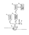
では、このような直流地絡電流検出回路を使用する系統連系システムにおいて、この直流地絡電流検出回路がどのように使用されるかについて説明する。図10は一般的な系統連系システムの概略構成を示すブロック図である。 Now, how the DC ground fault current detection circuit is used in a grid interconnection system using such a DC ground fault current detection circuit will be described. FIG. 10 is a block diagram showing a schematic configuration of a general grid interconnection system.
図10に示す系統連系システム100は、太陽電池等の直流電源101と、例えば単相3線式の交流系統102と、これら直流電源101及び交流系統102間に配置され、直流電源101の直流電力を交流電力に変換する系統連系装置103とを有し、この系統連系装置103は、直流電源101からの直流電力を交流電力に変換するインバータ104と、交流系統102との連系をON/OFF制御する連系リレー105と、インバータ104及び交流系統102間のU相の電源線110A及びW相の電源線110B間の電流差を磁気的に検出するZCT10と、このZCT10にて検出された電流差に基づいて直流地絡電流の発生の有無を検出する直流地絡電流検出回路107と、この直流地絡電流検出回路107の検出結果に基づいてインバータ104及び連系リレー105等を制御するCPU108とを有している。
A
系統連系装置103のCPU108は、直流地絡電流検出回路107にて直流地絡電流が発生したとの検出結果を得ると、連系リレー105をOFF制御することで、交流系統102との連系を遮断するものである。
When the
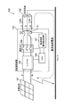
図11は直流地絡電流検出回路107内部の概略構成を示すブロック図である。図12は直流地絡電流検出回路107内部の各出力波形を通じて同直流地絡電流検出回路107の動作を端的に示す説明図、図12(a)は直流地絡電流の発生と判断しない場合、図12(b)は直流地絡電流の発生と判断する場合である。
FIG. 11 is a block diagram showing a schematic configuration inside the DC ground fault
直流地絡電流検出回路107は、U相の電源線110A及びW相の電源線110Bを挿通することで、各電源線110A,110Bの電流差を磁気的に検出し、この電流差で生じる磁界変化に応じて自己インピーダンスを変動する、前述したZCT10と、所定電圧V1を発生する発振回路11と、ZCT10と直列に接続された分圧抵抗12と、ZCT10のインピーダンス変化に応じてZCT10及び分圧抵抗12間で分圧された電圧値V2に基づいて比較電圧値V5を生成する比較電圧値生成回路13と、この比較電圧値生成回路13にて生成した比較電圧値V5が地絡判定用閾値以上であるか否かを判定し、この判定結果に基づいて直流地絡電流の発生有無を検出する制御回路14とを有している。尚、電圧値V2は、ZCT10のインピーダンスをZ1、分圧抵抗12の抵抗値をR1とすると、Z1/(Z1+R1)*V1で求めることができる。
The DC ground fault
比較電圧値生成回路13は、図12(a)又は(b)に示すように、電圧値V2を検出すると、この電圧値V2を整流する整流回路131と、この整流回路131からの出力電圧V3をオフセット増幅するオフセット増幅回路132と、このオフセット増幅回路132からの出力電圧V4をフィルタ処理することで比較電圧値V5を出力するフィルタ回路133とを有している。
When the comparison voltage
制御回路14は、図12(b)に示すように、比較電圧値生成回路13からの比較電圧値V5が地絡判定用閾値(所定レベル)以上であると判定されると、電源線110A,110Bに直流地絡電流が発生したものと判断するものである。
As shown in FIG. 12B, the
また、制御回路14は、図12(a)に示すように、比較電圧値V5が地絡判定用閾値以上でないと判定されると、直流地絡電流が発生していないものと判断するものである。
Further, as shown in FIG. 12A, the
従って、従来の直流地絡電流検出回路107によれば、ZCT10のインピーダンス変化に応じてZCT10及び分圧抵抗12間で分圧された電圧値V2に基づいて比較電圧値V5を生成し、この比較電圧値V5が地絡判定用閾値以上であると判定されると、直流地絡電流が発生したものと判断し、地絡判定用閾値以上でないと判定されると、直流地絡電流が発生していないものと判断するようにしたので、直流地絡電流の発生の有無を確実に検出することができる。
Therefore, according to the conventional DC ground fault
尚、図10に示す系統連系装置100においては、単相3線方式の交流系統102を例にあげて、U相の電源線110A及びW相の電源線110BをZCT10に挿通させるようにしたが、例えば単相2線方式の交流系統102の場合、L相の電源線及びN相の電源線をZCT10に挿通させることで、直流地絡電流検出回路107では、単相2線方式であっても、同様に直流地絡電流の発生の有無を確実に認識することができるものである。
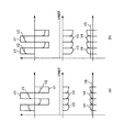
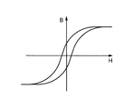
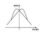
上記従来の直流地絡電流検出回路107によれば、電源線110A,110Bの電流差を検出するZCT10は磁性材料のパーマロイを使用しているため、図13に示すヒステリシス特性を有することになるため、そのZCT10の透磁率−磁化電流特性は図14に示すようになる。
According to the conventional DC ground fault
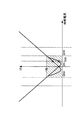
しかしながら、このようなZCT10を使用した直流地絡電流検出回路107によれば、ZCT10のヒステリシス特性の影響を受けて微小電流範囲、例えば図15に示すように、−30mA〜+30mAといった直流地絡電流の発生有無を判断する電流範囲(斜線部分)で、例えば15mAの直流電流値を検出するような場合には比較電圧値V5が2点となるため、比較電圧値V5に基づく正確な直流電流値の検出が困難となり、その結果、直流地絡電流の発生の有無を正確に検出することができなくなる。
However, according to the DC ground fault
また、直流地絡電流検出回路107に限らず、一般的な直流電流検出回路においても、同様に、ZCT10のヒステリシス特性の影響を受けて、比較電圧値に基づいて、現在の直流電流値を正確に検出することができない。
Further, not only the DC ground fault
本発明は上記点に鑑みてなされたものであり、その目的とするところは、ZCTのヒステリシス特性の影響を受けることなく、現在の直流電流値を正確に検出することができる直流電流検出回路を提供することにある。 The present invention has been made in view of the above points, and an object of the present invention is to provide a direct current detection circuit capable of accurately detecting the current direct current value without being affected by the hysteresis characteristics of ZCT. It is to provide.
また、本発明は上記点に鑑みてなされたものであり、その目的とするところは、ZCTのヒステリシス特性の影響を受けることなく、直流地絡電流の発生の有無を正確に検出することができる直流地絡電流検出回路を提供することにある。 In addition, the present invention has been made in view of the above points, and an object of the present invention is to accurately detect the presence or absence of a DC ground fault current without being affected by the hysteresis characteristics of ZCT. The object is to provide a DC ground fault current detection circuit.
上記目的を達成するために本発明の直流電流検出回路は、電源線を挿通することで、各電源線の電流差を磁気的に検出し、この電流差で生じる磁界変化に応じて自己インピーダンスを変動する、分圧抵抗に直列に接続された零相変流器と、この零相変流器のインピーダンス変化に応じて前記零相変流器及び前記分圧抵抗間で分圧された電圧値に基づいて比較電圧値を生成する比較電圧値生成回路と、この比較電圧値生成回路にて生成した比較電圧値に基づいて、現在の直流電流値を検出する制御回路とを有する直流電流検出回路であって、前記零相変流器に挿通されるオフセット用電線と、前記零相変流器のヒステリシス特性の影響を受けて、前記比較電圧値に基づく正確な直流電流値の検出を困難とする電流範囲での、前記比較電圧値に基づく直流電流値の検出を可能とすべく、前記オフセット用電線にオフセット電流を発生するオフセット電流発生回路と、前記電源線を挿通すると共に、前記零相変流器にて検出するオフセット電流とは逆方向のオフセット電流が検出されるように、前記オフセット用電線を挿通する、前記零相変流器と同一特性の補償用零相変流器と、この補償用零相変流器に直列に接続され、前記分圧抵抗と同一特性の補償用分圧抵抗と、前記補償用零相変流器のインピーダンス変化に応じて前記補償用零相変流器及び前記補償用分圧抵抗間で分圧される電圧値に基づいて補償用比較電圧値を生成する補償用比較電圧値生成回路とを有して構成し、前記制御回路が、前記比較電圧値生成回路にて生成した比較電圧値に基づいて正方向の電流値を検出し、この正方向の電流値及び前記オフセット電流分の電流値に基づいて正方向の直流電流値を算出すると共に、前記補償用比較電圧値生成回路にて生成した補償用比較電圧値に基づいて逆方向の電流値を検出し、この逆方向の電流値及び前記オフセット電流分の電流値に基づいて逆方向の直流電流値を算出する直流電流値算出回路と、前記正方向の直流電流値及び前記逆方向の直流電流値の内、前記比較電圧値が前記補償用比較電圧値よりも高いと判定されると、前記正方向の直流電流値を選択し、この正方向の直流電流値を前記現在の直流電流値として検出すると共に、前記補償用比較電圧値が前記比較電圧値よりも高いと判定されると、前記逆方向の直流電流値を選択し、この逆方向の直流電流値を前記現在の直流電流値として検出する現在直流値検出回路とを有して構成するようにした。 In order to achieve the above object, the DC current detection circuit of the present invention magnetically detects the current difference of each power supply line by inserting the power supply line, and reduces the self impedance according to the magnetic field change caused by this current difference. A variable zero-phase current transformer connected in series with a voltage dividing resistor, and a voltage value divided between the zero-phase current transformer and the voltage dividing resistor in accordance with a change in impedance of the zero-phase current transformer. DC voltage detection circuit having a comparison voltage value generation circuit for generating a comparison voltage value based on the reference voltage and a control circuit for detecting a current DC current value based on the comparison voltage value generated by the comparison voltage value generation circuit In this case, it is difficult to accurately detect the direct current value based on the comparison voltage value due to the influence of the offset wire inserted into the zero-phase current transformer and the hysteresis characteristic of the zero-phase current transformer. Based on the comparison voltage value in the current range to be Ku in order to enable the detection of the DC current value, and the offset current generating circuit for generating an offset current to the offset electric wire, as well as through the power line, the offset current detected by the zero-phase current transformer A compensation zero-phase current transformer having the same characteristics as the zero-phase current transformer, which is inserted through the offset wire, so as to detect an offset current in the reverse direction, and the compensation zero-phase current transformer in series. A voltage dividing resistor for compensation having the same characteristics as the voltage dividing resistor and a voltage dividing resistor between the compensating zero phase current transformer and the compensating voltage dividing resistor according to a change in impedance of the compensating zero phase current transformer. based on the voltage value divided constituted by organic and compensation comparison voltage value generation circuit for generating a compensation reference voltage value, wherein the control circuit, the comparison voltage values generated by the comparison voltage value generating circuit detecting a positive direction of the current value based, this To calculate the positive direction of the DC current value based on the direction of the current value and the current value of the offset current component, on the basis of the compensation reference voltage value generated by the compensation reference voltage value generation circuit of reverse current A DC current value calculation circuit that detects a value and calculates a DC current value in the reverse direction based on the current value in the reverse direction and the current value corresponding to the offset current; and the DC current value in the forward direction and the reverse direction When it is determined that the comparison voltage value is higher than the compensation comparison voltage value among the DC current values, the DC current value in the positive direction is selected, and the DC current value in the positive direction is set as the current DC current. and detects a value, the the compensation reference voltage value is determined to be higher than the comparison voltage value, the select reverse DC current value, the DC current value of the reverse direction of the current direct current Current DC value detected as a value And a detection circuit .
本発明の直流電流検出回路は、電源線を挿通することで、各電源線の電流差を磁気的に検出し、この電流差で生じる磁界変化に応じて自己インピーダンスを変動する、分圧抵抗に直列に接続された零相変流器と、この零相変流器のインピーダンス変化に応じて前記零相変流器及び前記分圧抵抗間で分圧された電圧値に基づいて比較電圧値を生成する比較電圧値生成回路と、この比較電圧値生成回路にて生成した比較電圧値に基づいて、現在の直流電流値を検出する制御回路とを有する直流電流検出回路であって、前記零相変流器に挿通されるオフセット用電線と、前記零相変流器のヒステリシス特性の影響を受けて、前記比較電圧値に基づく正確な直流電流値の検出を困難とする電流範囲での、前記比較電圧値に基づく直流電流値の検出を可能とすべく、前記オフセット用電線に所定周期毎に電流値の異なるオフセット電流を発生する機能を有するオフセット電流発生回路とを有して構成し、前記制御回路が、前記比較電圧値生成回路にて生成した比較電圧値に基づいて正方向の電流値及び逆方向の電流値を検出し、前記正方向の電流値及び前記オフセット電流分の電流値に基づいて正方向の直流電流値を算出すると共に、前記逆方向の電流値及び前記オフセット電流分の電流値に基づいて逆方向の直流電流値を算出する直流電流値算出回路と、前記正方向の直流電流値及び前記逆方向の直流電流値を算出すると、前記電流値検出時に関わる前記オフセット電流値と前記比較電圧値との変動推移を監視する変動推移監視回路と、この変動推移監視回路にて、前記オフセット電流値が高くなると、前記比較電圧値も高くなる変動推移を検出すると、前記正方向の直流電流値を前記現在の直流電流値として検出すると共に、前記オフセット電流値が高くなると、前記比較電圧値が低くなる変動推移を検出すると、前記逆方向の直流電流値を前記現在の直流電流値として検出する現在直流値検出回路とを有して構成するようにした。 The DC current detection circuit of the present invention is a voltage dividing resistor that magnetically detects the current difference between the power supply lines by inserting the power supply line and fluctuates the self-impedance according to the magnetic field change caused by the current difference. A zero-phase current transformer connected in series and a comparison voltage value based on a voltage value divided between the zero-phase current transformer and the voltage dividing resistor according to the impedance change of the zero-phase current transformer. A direct current detection circuit comprising: a comparison voltage value generation circuit to be generated; and a control circuit for detecting a current direct current value based on the comparison voltage value generated by the comparison voltage value generation circuit, wherein the zero phase In the current range in which it is difficult to accurately detect a direct current value based on the comparison voltage value due to the influence of the hysteresis characteristics of the offset wire inserted through the current transformer and the zero-phase current transformer. DC current value can be detected based on the comparison voltage value In order to the make up and a offset current generation circuit having a function of generating a different offset current of the current value for each predetermined period to the offset electric wire, the control circuit, in the comparison voltage value generating circuit together on the basis of the generated comparison voltage value detected in the positive direction of the current value and the reverse current value to calculate the positive direction of the current value and the positive direction of the DC current value based on the current value of the offset current component a DC current value calculating circuit for calculating a reverse direct current value based on the current value and the current value of the offset current component of the reverse, the positive direction of the DC current value and the DC current value of the reverse When calculated, a fluctuation transition monitoring circuit for monitoring a fluctuation transition between the offset current value and the comparison voltage value involved in the detection of the current value, and the offset current value is calculated by the fluctuation transition monitoring circuit. And Kunar, when detecting variations transition made higher the comparison voltage value, and detects the positive direction of the DC current value said as the current of the DC current value and the offset current value is high, the comparison voltage value is lower Upon detecting a variation trend was a DC current value of the reverse direction to configure possess the current DC value detecting circuit for detecting said as the current of the DC current value.
本発明の直流電流検出回路は、電源線を挿通することで、各電源線の電流差を磁気的に検出し、この電流差で生じる磁界変化に応じて自己インピーダンスを変動する、分圧抵抗に直列に接続された零相変流器と、この零相変流器のインピーダンス変化に応じて前記零相変流器及び前記分圧抵抗間で分圧された電圧値に基づいて比較電圧値を生成する比較電圧値生成回路と、この比較電圧値生成回路にて生成した比較電圧値に基づいて、前記電源線に関わる直流地絡電流の発生の有無を検出する制御回路とを有する直流地絡電流検出回路であって、前記零相変流器に挿通されるオフセット用電線と、前記零相変流器のヒステリシス特性の影響を受けて、前記比較電圧値に基づく正確な直流地絡電流の直流電流値の検出を困難とする電流範囲を、前記比較電圧値に基づく直流電流値の検出を可能とする電流検出可能範囲にシフトすべく、前記オフセット用電線にオフセット電流を発生するオフセット電流発生回路と、前記電流検出可能範囲内の直流地絡電流発生判断に関わる直流電流値に対応した地絡判定用上限閾値及び地絡判定用下限閾値を記憶管理した地絡判定用閾値メモリと、前記電源線を挿通すると共に、前記零相変流器にて検出するオフセット電流とは逆方向のオフセット電流が検出されるように、前記オフセット用電線を挿通する、前記零相変流器と同一特性の補償用零相変流器と、この補償用零相変流器に直列に接続され、前記分圧抵抗と同一特性の補償用分圧抵抗と、前記補償用零相変流器のインピーダンス変化に応じて前記補償用零相変流器及び前記補償用分圧抵抗間で分圧される電圧値に基づいて補償用比較電圧値を生成する補償用比較電圧値生成回路とを有して構成し、前記制御回路が、前記比較電圧値生成回路にて比較電圧値を生成し、この比較電圧値が前記地絡判定用上限閾値以上であると判定されると、前記正方向の直流地絡電流が発生したものと判断すると共に、前記補償用比較電圧値生成回路にて補償用比較電圧値を生成し、この補償用比較電圧値が前記地絡判定用上限閾値以上であると判定されると、前記逆方向の直流地絡電流が発生したものと判断する直流地絡判定回路を有するようにした。 The DC current detection circuit of the present invention is a voltage dividing resistor that magnetically detects the current difference between the power supply lines by inserting the power supply line and fluctuates the self-impedance according to the magnetic field change caused by the current difference. A zero-phase current transformer connected in series and a comparison voltage value based on a voltage value divided between the zero-phase current transformer and the voltage dividing resistor according to the impedance change of the zero-phase current transformer. DC ground fault having a comparison voltage value generating circuit to be generated and a control circuit for detecting the presence or absence of generation of a DC ground fault current related to the power supply line based on the comparison voltage value generated by the comparison voltage value generating circuit A current detection circuit, which is influenced by the hysteresis characteristics of the offset wire inserted into the zero-phase current transformer and the zero-phase current transformer, and is capable of accurately detecting a DC ground fault current based on the comparison voltage value. A current range that makes DC current value detection difficult. An offset current generating circuit for generating an offset current in the offset wire to shift to a current detectable range that enables detection of a DC current value based on the comparison voltage value, and a DC ground fault in the current detectable range A ground fault judgment threshold memory that stores and manages a ground fault judgment upper limit threshold value and a ground fault judgment lower limit threshold value corresponding to a DC current value related to current generation judgment, and the zero-phase current transformer while being inserted through the power line. A compensating zero-phase current transformer having the same characteristics as the zero-phase current transformer, which is inserted through the offset wire, so that an offset current in a direction opposite to the offset current detected in the first and second currents is detected. A compensation voltage dividing resistor connected in series to the zero phase current transformer, having the same characteristics as the voltage dividing resistance, and the compensation zero phase current transformer according to the impedance change of the compensation zero phase current transformer, Voltage divider resistor for compensation A compensation comparison voltage value generating circuit that generates a compensation comparison voltage value based on the voltage value divided by the control voltage, and the control circuit generates the comparison voltage value in the comparison voltage value generation circuit. If the comparison voltage value is determined to be equal to or greater than the ground fault determination upper limit threshold value, it is determined that the positive DC ground fault current has occurred, and the compensation comparison voltage value generation circuit A compensation reference voltage value is generated, and when it is determined that the compensation comparison voltage value is equal to or greater than the ground fault determination upper limit threshold value, the DC ground is determined to have generated the reverse DC ground fault current. It was made to have a fault determination circuit .
本発明の直流電流検出回路は、電源線を挿通することで、各電源線の電流差を磁気的に検出し、この電流差で生じる磁界変化に応じて自己インピーダンスを変動する、分圧抵抗に直列に接続された零相変流器と、この零相変流器のインピーダンス変化に応じて前記零相変流器及び前記分圧抵抗間で分圧された電圧値に基づいて比較電圧値を生成する比較電圧値生成回路と、この比較電圧値生成回路にて生成した比較電圧値に基づいて、前記電源線に関わる直流地絡電流の発生の有無を検出する制御回路とを有する直流地絡電流検出回路であって、前記零相変流器に挿通されるオフセット用電線と、前記零相変流器のヒステリシス特性の影響を受けて、前記比較電圧値に基づく正確な直流地絡電流の直流電流値の検出を困難とする電流範囲を、前記比較電圧値に基づく直流電流値の検出を可能とする電流検出可能範囲にシフトすべく、前記オフセット用電線に所定周期毎に電流値の異なるオフセット電流を発生するオフセット電流発生回路と、前記電流検出可能範囲内の直流地絡電流発生判断に関わる直流電流値に対応した地絡判定用上限閾値及び地絡判定用下限閾値を記憶管理した地絡判定用閾値メモリとを有して構成し、前記制御回路が、前記電源線に関わる直流地絡電流が発生したものと判断されると、この直流地絡電流発生判断時に関わる前記オフセット電流値と前記比較電圧値との変動推移を監視する変動推移監視回路と、この変動推移監視回路にて、前記オフセット電流値が高くなると、前記比較電圧値も高くなる変動推移を検出すると、前記正方向の直流地絡電流が発生したものと判断すると共に、前記オフセット電流値が高くなると、前記比較電圧値が低くなる変動推移を検出すると、前記逆方向の直流地絡電流が発生したものと判断する直流地絡判定回路とを有して構成するようにした。 The DC current detection circuit of the present invention is a voltage dividing resistor that magnetically detects the current difference between the power supply lines by inserting the power supply line and fluctuates the self-impedance according to the magnetic field change caused by the current difference. A zero-phase current transformer connected in series and a comparison voltage value based on a voltage value divided between the zero-phase current transformer and the voltage dividing resistor according to the impedance change of the zero-phase current transformer. a comparison voltage generation circuit to be generated, based on the comparison voltage values generated by this comparison voltage value generating circuit, a DC ground fault and a control circuit for detecting the occurrence of DC ground fault current relating to the power line A current detection circuit, which is influenced by the hysteresis characteristics of the offset wire inserted into the zero-phase current transformer and the zero-phase current transformer, and is capable of accurately detecting a DC ground fault current based on the comparison voltage value. A current range that makes DC current value detection difficult. An offset current generating circuit for generating an offset current having a different current value for each predetermined period in the offset wire in order to shift to a current detectable range that enables detection of a DC current value based on the comparison voltage value; and the current A ground fault determination threshold memory that stores and manages the ground fault determination upper limit threshold and the ground fault determination lower limit threshold corresponding to the DC current value related to the DC ground fault current generation determination within the detectable range, When the control circuit determines that a DC ground fault current related to the power supply line has been generated, a change for monitoring a change transition of the offset current value and the comparison voltage value related to the determination of the DC ground fault current generation When the transition monitoring circuit and the variation transition monitoring circuit detect a variation transition in which the comparison voltage value increases when the offset current value increases, the DC ground fault current in the positive direction is generated. A DC ground fault determination circuit that determines that a reverse DC ground fault current has been generated when a fluctuation transition in which the comparison voltage value decreases as the offset current value increases is determined. It was made to have .
上記のように構成された本発明の直流電流検出回路によれば、零相変流器のヒステリシス特性の影響を受けて、比較電圧値に基づく正確な直流電流値の検出を困難とする電流範囲(微小電流範囲)での、比較電圧値に基づく直流電流値の検出を可能とすべく、オフセット電流を零相変流器に流して同電流範囲をオフセット電流分だけシフトすることで、比較電圧値に基づく電流値検出を可能とし、この電流値及びオフセット電流分の電流値に基づいて直流電流値を算出し、この直流電流値を現在の直流電流値として検出するようにしたので、零相変流器のヒステリシス特性の影響を受けることなく、正確に現在の直流電流値を検出することができる。 According to the DC current detection circuit of the present invention configured as described above, the current range that makes it difficult to accurately detect the DC current value based on the comparison voltage value due to the influence of the hysteresis characteristic of the zero-phase current transformer. In order to enable detection of a direct current value based on the comparison voltage value in the (small current range), an offset current is passed through the zero-phase current transformer, and the current range is shifted by the offset current, thereby comparing voltage The current value detection based on the value is possible, the direct current value is calculated based on the current value and the current value for the offset current, and this direct current value is detected as the current direct current value. The current direct current value can be accurately detected without being affected by the hysteresis characteristics of the current transformer.
本発明の直流電流検出回路によれば、零相変流器にて検出するオフセット電流とは逆方向のオフセット電流が検出されるようにオフセット用電線及び電源線を挿通すると共に、補償用分圧抵抗と直列に接続する、前記零相変流器と同一特性の補償用零相変流器と、この補償用零相変流器のインピーダンス変化に応じて補償用零相変流器及び補償用分圧抵抗間で分圧される電圧値に基づいて補償用比較電圧値を生成する補償用比較電圧値生成回路とを有し、比較電圧値に基づいて正方向の直流電流値を算出すると共に、補償用比較電圧値に基づいて逆方向の直流電流値を算出し、前記比較電圧値が前記補償用比較電圧値よりも高いと判定されると、前記正方向の直流電流値を現在の直流電流値として検出すると共に、前記補償用比較電圧値が前記比較電圧値よりも高いと判定されると、前記逆方向の直流電流値を前記現在の直流電流値として検出するようにしたので、零相変流器のヒステリシス特性の影響を受けることなく、現在の直流電流値を正確に検出することができることはもちろんのこと、現在の直流電流値が正方向又は逆方向に急峻に変化したとしても、同直流電流値が正方向の直流電流値であるか、又は逆方向の直流電流値であるかを正確に検出することができる。 According to the DC current detection circuit of the present invention, the offset electric wire and the power supply line are inserted so that the offset current in the direction opposite to the offset current detected by the zero-phase current transformer is detected, and the compensation voltage dividing Compensating zero-phase current transformer having the same characteristics as the zero-phase current transformer connected in series with the resistor, and the compensating zero-phase current transformer and the compensating zero-phase current transformer according to the impedance change of the compensating zero-phase current transformer A compensation comparison voltage value generating circuit that generates a compensation comparison voltage value based on a voltage value divided between the voltage dividing resistors, and calculating a positive direct current value based on the comparison voltage value Then, a reverse direct current value is calculated based on the compensation comparison voltage value, and if it is determined that the comparison voltage value is higher than the compensation comparison voltage value, the forward direct current value is converted to the current direct current value. In addition to detecting the current value, the compensation comparison voltage value is If it is determined that the voltage is higher than the comparison voltage value, the current value in the reverse direction is detected as the current DC current value, so that the current value is not affected by the hysteresis characteristics of the zero-phase current transformer. In addition to being able to detect the DC current value of the current accurately, even if the current DC current value changes sharply in the forward or reverse direction, is the DC current value in the positive direction? Or a direct current value in the reverse direction can be accurately detected.
本発明の直流電流検出回路によれば、所定周期毎に電流値の異なるオフセット電流を流し、前記比較電圧値生成回路にて生成した比較電圧値に基づいて正方向の直流電流値及び逆方向の直流電流値を算出すると、電流値検出時に関わるオフセット電流値と比較電圧値との変動推移を監視し、前記オフセット電流値が高くなると、前記比較電圧値も高くなる変動推移を検出すると、前記正方向の直流電流値を前記現在の直流電流値として検出すると共に、前記オフセット電流値が高くなると、前記比較電圧値が低くなる変動推移を検出すると、前記逆方向の直流電流値を前記現在の直流電流値として検出するようにしたので、零相変流器のヒステリシス特性の影響を受けることなく、現在の直流電流値を正確に検出することができることはもちろんのこと、補償用零相変流器、補償用分圧抵抗や補償用比較電圧値生成回路を設けなくても、現在の直流電流値が正方向又は逆方向に急峻に変化としても、同直流電流値が正方向の直流電流値、若しくは逆方向の直流電流値であるかを正確に検出することができる。 According to the DC current detection circuit of the present invention, an offset current having a different current value is caused to flow every predetermined period, and the DC current value in the forward direction and the reverse direction current value based on the comparison voltage value generated by the comparison voltage value generation circuit. When the DC current value is calculated, the fluctuation transition between the offset current value and the comparison voltage value related to the detection of the current value is monitored, and when the fluctuation transition in which the comparison voltage value increases as the offset current value increases, the positive current value is detected. When the DC current value in the direction is detected as the current DC current value, and the fluctuation transition in which the comparison voltage value decreases as the offset current value increases, the DC current value in the reverse direction is detected as the current DC current value. Since the current value is detected, the current DC current value can be accurately detected without being affected by the hysteresis characteristics of the zero-phase current transformer. Even if there is no compensation zero-phase current transformer, compensation voltage dividing resistor or compensation comparison voltage value generation circuit, even if the current DC current value changes sharply in the forward or reverse direction, the same It is possible to accurately detect whether the direct current value is a forward direct current value or a reverse direct current value.
本発明の直流電流検出回路によれば、零相変流器のヒステリシス特性の影響を受けて、比較電圧値に基づく正確な直流電流値の検出を困難とする電流範囲での、比較電圧値に基づく直流電流値の検出を可能とすべく、前記零相変流器に対して、前記電源線を複数回挿通するように構成することで、同電流範囲を挿通回数の電流分だけシフトすることで、比較電圧値に基づく電流値検出を可能とし、この電流値及び挿通回数の電流分の電流値に基づいて直流電流値を算出し、この直流電流値を現在の直流電流値として検出するようにしたので、オフセット電流発生回路等の別回路を設けなくても、その電源線の挿通回数を変えるだけで、零相変流器のヒステリシス特性の影響を受けることなく、正確に現在の直流電流値を検出することができる。 According to the direct current detection circuit of the present invention, the comparison voltage value in the current range in which it is difficult to accurately detect the direct current value based on the comparison voltage value due to the hysteresis characteristic of the zero-phase current transformer. In order to enable detection of a direct current value based on the zero-phase current transformer, the power line is configured to be inserted a plurality of times, thereby shifting the current range by the number of insertions. The current value can be detected based on the comparison voltage value, the direct current value is calculated based on the current value and the current value corresponding to the number of insertions, and the direct current value is detected as the current direct current value. Therefore, even if no separate circuit such as an offset current generation circuit is provided, it is possible to accurately change the current DC current without affecting the hysteresis characteristics of the zero-phase current transformer simply by changing the number of insertions of the power line. Value can be detected
上記のように構成された本発明の直流地絡電流検出回路によれば、前記零相変流器のヒステリシス特性の影響を受けて、比較電圧値に基づく正確な直流地絡電流の直流電流値の検出を困難とする電流範囲(微小電流範囲)を、比較電圧値に基づく直流電流値の検出を可能とする電流検出可能範囲にシフトすべく、零相変流器にオフセット電流を流し、前記電流検出可能範囲内の直流地絡電流発生判断に関わる直流電流値に対応した地絡判定用上限閾値及び地絡判定用下限閾値を記憶管理しておき、前記比較電圧値生成回路にて比較電圧値を生成し、この比較電圧値が地絡判定用上限閾値以上であると判定されると、又は、前記比較電圧値が前記地絡判定用下限閾値以下であると判定されると、前記電源線に関わる直流地絡電流が発生したものと判断するようにしたので、零相変流器のヒステリシス特性の影響を受けることなく、直流地絡電流の発生の有無を正確に検出することができる。 According to the DC ground fault current detection circuit of the present invention configured as described above, the DC current value of the accurate DC ground fault current based on the comparison voltage value is affected by the hysteresis characteristic of the zero-phase current transformer. In order to shift the current range that makes it difficult to detect the current range (minute current range) to a current detectable range that enables detection of the DC current value based on the comparison voltage value, an offset current is passed through the zero-phase current transformer, The upper limit threshold for ground fault determination and the lower limit threshold for ground fault determination corresponding to the DC current value related to the determination of DC ground fault current generation within the current detectable range are stored and managed, and the comparison voltage value generating circuit compares the comparison voltage. If the comparison voltage value is determined to be greater than or equal to the ground fault determination upper limit threshold, or if the comparison voltage value is determined to be less than or equal to the ground fault determination lower limit threshold, the power supply DC ground fault current related to the wire Since so as to determine, it is without being affected by the hysteresis characteristic of the zero-phase current transformer, to accurately detect the occurrence of DC ground fault current that.
本発明の直流地絡電流検出回路によれば、零相変流器にて検出するオフセット電流とは逆方向のオフセット電流が検出されるようにオフセット用電線及び電源線を挿通すると共に、補償用分圧抵抗と直列に接続する、前記零相変流器と同一特性の補償用零相変流器と、この補償用零相変流器のインピーダンス変化に応じて補償用零相変流器及び補償用分圧抵抗間で分圧される電圧値に基づいて補償用比較電圧値を生成する補償用比較電圧値生成回路とを有し、比較電圧値生成回路にて生成した比較電圧値が地絡判定用上限閾値以上であると判定されると、正方向の直流地絡電流が発生したものと判断すると共に、前記補償用比較電圧値生成回路にて生成した補償用比較電圧値が前記地絡判定用上限閾値以上であると判定されると、前記逆方向の直流地絡電流が発生したものと判断するようにしたので、零相変流器のヒステリシス特性の影響を受けることなく、直流地絡電流の発生の有無を正確に検出することができることはもちろんのこと、直流地絡電流が正方向又は逆方向に急峻に発生したとしても、この直流地絡電流が正方向の直流地絡電流、若しくは逆方向の直流地絡電流であるかを正確に検出することができる。 According to the DC ground fault current detection circuit of the present invention, the offset wire and the power line are inserted so that the offset current in the direction opposite to the offset current detected by the zero-phase current transformer is detected, and the compensation current A compensation zero-phase current transformer connected in series with a voltage dividing resistor and having the same characteristics as the zero-phase current transformer, a compensation zero-phase current transformer according to the impedance change of the compensation zero-phase current transformer, and A compensation comparison voltage value generating circuit that generates a compensation comparison voltage value based on a voltage value divided between the compensation voltage dividing resistors, and the comparison voltage value generated by the comparison voltage value generation circuit is If it is determined that the value is equal to or greater than the upper limit threshold for determination of a fault, it is determined that a positive DC ground fault current has occurred, and the compensation comparison voltage value generated by the compensation comparison voltage value generation circuit is the ground voltage. When it is determined that the value is greater than or equal to the upper limit threshold for determination of entanglement, Since it was determined that a DC ground fault current was generated, it is possible to accurately detect the occurrence of a DC ground fault current without being affected by the hysteresis characteristics of the zero-phase current transformer. Even if the DC ground fault current is sharply generated in the forward direction or the reverse direction, it can be accurately detected whether the DC ground fault current is a positive DC ground fault current or a reverse DC ground fault current. be able to.
本発明の直流地絡電流検出回路によれば、所定周期毎に電流値の異なるオフセット電流を流し、前記電源線に関わる直流地絡電流が発生したものと判断されると、この直流地絡電流発生判断時に関わる前記オフセット電流値と前記比較電圧値との変動推移を監視し、前記オフセット電流値が高くなると、前記比較電圧値も高くなる変動推移を検出すると、前記正方向の直流地絡電流が発生したものと判断すると共に、前記オフセット電流値が高くなると、前記比較電圧値が低くなる変動推移を検出すると、前記逆方向の直流地絡電流が発生したものと判断するようにしたので、零相変流器のヒステリシス特性の影響を受けることなく、直流地絡電流の発生の有無を正確に検出することができることはもちろんのこと、補償用零相変流器、補償用分圧抵抗や補償用比較電圧値生成回路を設けなくても、直流地絡電流が正方向又は逆方向に急峻に発生したとしても、この直流地絡電流が正方向の直流地絡電流であるか、又は逆方向の直流地絡電流であるかを正確に検出することができる。 According to the DC ground fault current detection circuit of the present invention, when it is determined that a DC ground fault current related to the power supply line is generated by passing an offset current having a different current value every predetermined period, the DC ground fault current is detected. When the fluctuation transition between the offset current value and the comparison voltage value related to occurrence determination is monitored, and the fluctuation transition in which the comparison voltage value also increases when the offset current value increases, the DC ground fault current in the positive direction is detected. As the offset current value is increased, and the change transition when the comparison voltage value is decreased is detected, it is determined that the reverse DC ground fault current has occurred. Without being affected by the hysteresis characteristics of the zero-phase current transformer, it is possible to accurately detect the occurrence of DC ground fault current, as well as the compensation zero-phase current transformer and compensation Even if there is no voltage dividing resistor or compensation voltage generation circuit for compensation, even if the DC ground fault current steeply occurs in the forward or reverse direction, this DC ground fault current is the positive DC ground fault current. Or a DC ground fault current in the reverse direction can be accurately detected.
本発明の直流地絡電流検出回路によれば、零相変流器のヒステリシス特性の影響を受けて、比較電圧値に基づく正確な直流地絡電流の直流電流値の検出を困難とする電流範囲を、前記比較電圧値に基づく直流電流値の検出を可能とする電流検出可能範囲にシフトすべく、前記零相変流器に対して、前記電源線を複数回挿通するように構成したので、オフセット電流発生回路等の別回路を設けなくても、その電源線の挿通回数を変えるだけで、零相変流器のヒステリシス特性の影響を受けることなく、直流地絡電流の発生の有無を正確に検出することができる。 According to the DC ground fault current detection circuit of the present invention, it is difficult to accurately detect the DC current value of the DC ground fault current based on the comparison voltage value under the influence of the hysteresis characteristic of the zero-phase current transformer. Since the zero-phase current transformer is configured to pass through the power supply line a plurality of times in order to shift to a current detectable range that enables detection of a direct current value based on the comparison voltage value, Even if no separate circuit such as an offset current generator is provided, the presence or absence of a DC ground fault current can be accurately detected without changing the hysteresis characteristics of the zero-phase current transformer by simply changing the number of insertions of the power line. Can be detected.
以下、図面に基づいて本発明の直流電流検出回路(直流地絡電流検出回路)における実施の形態を示す直流地絡電流検出回路について説明する。尚、図10及び図11に示す直流地絡電流検出回路107と同一のものには同一符号を付すことで、その重複する構成及び動作の説明については省略する。
Hereinafter, a DC ground fault current detection circuit showing an embodiment of a DC current detection circuit (DC ground fault current detection circuit) of the present invention will be described with reference to the drawings. The same components as those of the DC ground fault
(実施の形態1)
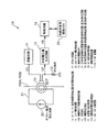
では、第1の実施の形態を示す直流地絡電流検出回路について説明する。図1は第1の実施の形態を示す直流地絡電流検出回路内部の概略構成を示すブロック図である。
(Embodiment 1)
Now, the DC ground fault current detection circuit showing the first embodiment will be described. FIG. 1 is a block diagram showing a schematic configuration inside the DC ground fault current detection circuit showing the first embodiment.
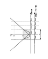
図1に示す直流地絡電流検出回路1Aは、電源線110A及び110Bを挿通するZCT10、発振回路11、分圧抵抗12及び比較電圧値生成回路13の他に、ZCT10に挿通されるオフセット用電線21と、図2に示すように、ZCT10のヒステリシス特性の影響を受けて、比較電圧値V5に基づく正確な直流地絡電流の直流電流値の検出を困難とする電流範囲X(斜線部分)を、比較電圧値V5に基づく直流電流値の検出を可能とする電流検出可能範囲にシフトすべく、オフセット用電線21にオフセット電流を発生するオフセット電流発生回路22と、電流検出可能範囲内の直流地絡電流発生判断に関わる直流電流値に対応した地絡判定用上限閾値VA及び地絡判定用下限閾値VBを記憶管理した地絡判定用閾値メモリ23と、比較電圧値生成回路13にて生成した比較電圧値V5が地絡判定用上限閾値VA以上であると判定されると、又は、比較電圧値V5が地絡判定用下限閾値VB以下であると判定されると、電源線110A,110Bに関わる直流地絡電流が発生したものと判断する制御回路14Aとを有している。
A DC ground fault
オフセット電流発生回路22は、例えば60mAのオフセット電流をオフセット用電線21に常時流しているものとする。
It is assumed that the offset
尚、請求項1記載の直流電流検出回路及び請求項5記載の直流地絡電流検出回路は直流地絡電流検出回路1A、制御回路は制御回路14Aに相当するものである。
The DC current detection circuit according to claim 1 and the DC ground fault current detection circuit according to claim 5 correspond to the DC ground fault
次に第1の実施の形態を示す直流地絡電流検出回路1Aの動作について説明する。
Next, the operation of the DC ground fault
オフセット電流発生回路21は、オフセット用電線21に60mAのオフセット電流を常時流す。従って、ZCT10のヒステリシス特性の影響で比較電圧値V5に基づく直流地絡電流の正確な検出ができなかった電流範囲(−30mA〜+30mA)は、図2に示すように、+60mAのオフセット電流で、ヒステリシス特性の影響を受けない+30mA〜+90mAの電流範囲にシフトされることになる。その結果、比較電圧値V5に基づく、−30mA〜+30mAの直流地絡電流の正確な検出が可能となる。
The offset
比較電圧値生成回路13は、ZCT10のインピーダンス変動に応じてZCT10及び分圧抵抗12間で分圧される電圧値V2を検出すると、この電圧値V2に基づいて比較電圧値V5を生成する。
When the comparison voltage
比較電圧値生成回路13は、比較電圧値V5を生成すると、この比較電圧値V5を制御回路14Aに伝送することになる。
When the comparison voltage
制御回路14Aは、比較電圧値V5を検出すると、この比較電圧値V5が地絡判定用上限閾値VA以上であるか否かを判定する。 When detecting the comparison voltage value V5, the control circuit 14A determines whether or not the comparison voltage value V5 is equal to or greater than the ground fault determination upper limit threshold VA.
制御回路14Aは、比較電圧値V5が地絡判定用上限閾値VA以上であると判定されると、その直流地絡電流が30mA以上であると判断し、電源線110A,110Bに関わる直流地絡電流が発生したものと判断する。
When it is determined that the comparison voltage value V5 is equal to or higher than the ground fault determination upper limit threshold VA, the control circuit 14A determines that the DC ground fault current is 30 mA or higher, and the DC ground fault related to the
また、制御回路14Aは、比較電圧値V5が地絡判定用下限閾値VB以下であるか否かを判定する。 Further, the control circuit 14A determines whether or not the comparison voltage value V5 is equal to or lower than the ground fault determination lower limit threshold VB.
制御回路14Aは、比較電圧値V5が地絡判定用下限閾値VB以下であると判定されると、その直流地絡電流が−30mA以下であると判断し、電源線110A,110Bに関わる直流地絡電流が発生したものと判断する。
When it is determined that the comparison voltage value V5 is equal to or less than the ground fault determination lower limit threshold VB, the control circuit 14A determines that the DC ground fault current is −30 mA or less, and the DC ground related to the
また、制御回路14Aは、比較電圧値V5が地絡判定用上限閾値VA以上でなく、地絡判定用下限閾値VB以下でなければ、電源線110A,110Bに関わる直流地絡電流が発生していないものと判断する。
The control circuit 14A generates a DC ground fault current related to the
第1の実施の形態によれば、ZCT10のヒステリシス特性の影響を受ける電流範囲(微小電流範囲)を、比較電圧値V5に基づく直流電流値の検出を可能とする電流検出可能範囲にシフトすべく、ZCT10にオフセット電流を流し、電流検出可能範囲内の直流地絡電流発生判断に関わる直流電流値に対応した地絡判定用上限閾値VA及び地絡判定用下限閾値VBを記憶管理しておき、比較電圧値生成回路13にて生成した比較電圧値V5が地絡判定用上限閾値VA以上であると判定されると、又は、比較電圧値V5が地絡判定用下限閾値VB以下であると判定されると、電源線110A,110Bに関わる直流地絡電流が発生したものと判断するようにしたので、ZCT10のヒステリシス特性の影響を受けることなく、直流地絡電流の発生の有無を正確に検出することができる。
According to the first embodiment, the current range (minute current range) affected by the hysteresis characteristics of the
尚、上記第1の実施の形態においては、ZCT10のヒステリシス特性の影響を受ける電流範囲をオフセット電流にて電流検出可能範囲にシフトすることで、比較電圧値V5に基づく直流地絡電流の発生有無を検出する直流地絡電流検出回路1Aについて説明したが、現在の直流電流値を検出する直流電流検出回路についても適用可能であることは言うまでもなく、この場合、オフセット電流にて電流検出可能範囲にシフトすることで比較電圧値V5に基づく電流値検出を可能とし、この電流値及びオフセット電流分の電流値に基づいて直流電流値を算出し、この直流電流値を現在の直流電流値として検出するようにすれば、、ZCT10のヒステリシス特性の影響を受けることなく、正確に現在の直流電流値を検出することができる。
In the first embodiment described above, whether or not a DC ground fault current is generated based on the comparison voltage value V5 by shifting the current range affected by the hysteresis characteristic of the
また、上記第1の実施の形態に示す直流地絡電流検出回路1Aでは、比較電圧値V5が地絡判定用上限閾値VA以上であると判定されると、直流地絡電流が発生したものと判断するが、比較電圧値V5が地絡判定用上限閾値VA以上の場合、図4に示すように直流地絡電流は+30mA以上の正方向の場合と、−150mA以上の逆方向の場合とが考えられる。また、同様に比較電圧値V5が地絡判定用下限閾値VB以下の場合、直流地絡電流が−30mA以下の正方向の場合と、−90mA以下の逆方向の場合とが考えられる。尚、正方向の直流地絡電流とは、図4に示す直流地絡電流+オフセット電流の0mAに対してプラス側の直流地絡電流、逆方向の直流地絡電流とは、直流地絡電流+オフセット電流の0mAに対してマイナス側の直流地絡電流に相当するものである。
In the DC ground fault
そこで、図1に示す直流地絡電流検出回路1Aによれば、地絡判定用下限閾値VB以下の比較電圧値V5に基づく直流電流値の監視を継続することで直流電流値の変動推移を監視し、この変動推移に基づいて、この直流地絡電流が正方向の直流地絡電流であるか、若しくは逆方向の直流地絡電流であるかを正確に検出することができる。
Therefore, according to the DC ground fault
しかしながら、この直流地絡電流検出回路1Aによれば、地絡判定用下限閾値VB以下の比較電圧値V5に基づく直流電流値の変動推移を監視することで、正方向の直流地絡電流であるか、若しくは逆方向の直流地絡電流であるかを正確に検出するようにしたが、その変動推移はあくまでも直流地絡電流が緩やかに変動した場合にのみ対処できるものであり、例えば直流地絡電流が0mAから急峻に−150mAに変化した場合、地絡判定用下限閾値VB以下の比較電圧値V5に基づく直流電流値の変動推移を監視することができないため、比較電圧値V5が地絡判定用上限閾値VA以上であるにも関わらず、+30mAの正方向の直流地絡電流であると判断してしまうおそれがある。
However, according to the DC ground fault
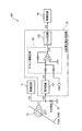
(実施の形態2)
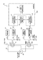
そこで、このような直流地絡電流が急峻に発生したとしても、直流地絡電流が正方向の直流地絡電流であるか、若しくは逆方向の直流地絡電流であるかを正確に検出することができる、第2の実施の形態を示す直流地絡電流検出回路について説明する。図3は第2の実施の形態を示す直流地絡電流検出回路内部の概略構成を示すブロック図である。尚、図1に示す直流地絡電流検出回路1Aと同一のものには同一符号を付すことで、その重複する構成及び動作の説明については省略する。
(Embodiment 2)
Therefore, even if such a DC ground fault current steeply occurs, it is possible to accurately detect whether the DC ground fault current is a positive DC ground fault current or a reverse DC ground fault current. A DC ground fault current detection circuit showing a second embodiment capable of performing the above will be described. FIG. 3 is a block diagram showing a schematic configuration inside the DC ground fault current detection circuit showing the second embodiment. In addition, the same code | symbol is attached | subjected to the same thing as 1 A of DC ground fault current detection circuits shown in FIG. 1, and the description of the overlapping structure and operation | movement is abbreviate | omitted.
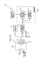
図3に示す直流地絡電流検出回路1Bは、電源線110A、110B及びオフセット用電線21を挿通するZCT10、発振回路11、比較電圧値生成回路13、オフセット電流発生回路22及び地絡判定用閾値メモリ23の他に、電源線110A、110Bを挿通すると共に、ZCT10にて検出するオフセット電流とは逆方向のオフセット電流が検出されるようにオフセット用電線21を挿通する、ZCT10と同一特性の補償用ZCT10Bと、補償用ZCT10Bに直列に接続され、分圧抵抗12と同一特性の補償用分圧抵抗12Bと、補償用ZCT10Bのインピーダンス変化に応じて補償用ZCT10B及び補償用分圧抵抗12B間で分圧される電圧値に基づいて補償用比較電圧値を生成する補償用比較電圧値生成回路13Bと、地絡判定用閾値メモリ23のメモリ内容、比較電圧値又は補償用比較電圧値に基づいて直流地絡電流の発生の有無を判断する制御回路14Bとを有している。
The DC ground fault
補償用ZCT10Bに流れるオフセット電流は、ZCT10に流れるオフセット電流(+60mA)と逆方向のオフセット電流、すなわち−60mAのオフセット電流が流れることになる。
As the offset current flowing through the
比較電圧値生成回路13は、比較電圧値V5に基づいて正方向の直流地絡電流を判別するものであり、補償用比較電圧用生成回路13Bは、補償用比較電圧値V5に基づいて逆方向の直流地絡電流を判別するものである。
The comparison voltage
制御回路14Bは、比較電圧値生成回路13にて生成した比較電圧値V5が地絡判定用上限閾値VA以上であるか否かを判定する正方向直流地絡判定回路31と、補償用比較電圧値生成回路13Bにて生成した補償用比較電圧値V5が地絡判定用上限閾値VA以上であるか否かを判定する逆方向直流地絡判定回路32と、正方向直流地絡判定回路31及び逆方向直流地絡判定回路32の判定結果に基づいて直流地絡電流が発生したか否かは勿論のこと、直流地絡電流が発生したと判断するにしても、正方向の直流地絡電流が発生したのか、若しくは逆方向の直流地絡電流が発生したのかを判断する直流地絡判定回路33とを有している。
The
直流地絡判定回路33は、正方向直流地絡判定回路31にて比較電圧値V5が地絡判定用上限閾値VA以上であると判定されると、正方向の直流地絡電流が発生したものと判断すると共に、逆方向直流地絡判定回路32にて補償用比較電圧値V5が地絡判定用上限閾値VA以上であると判定されると、逆方向の直流地絡電流が発生したものと判断するものである。
The DC ground fault determination circuit 33 generates a positive DC ground fault current when the positive DC ground
つまり、比較電圧値及び補償用比較電圧値の内、地絡判定用上限閾値VA以上であると判定された電圧値に基づいて、正方向の直流地絡電流であるか、若しくは逆方向の直流地絡電流であるかを判断するものである。 In other words, based on the voltage value determined to be equal to or higher than the ground fault determination upper limit threshold value VA among the comparison voltage value and the compensation comparison voltage value, it is a positive DC ground fault current or a reverse direct current. It is judged whether it is a ground fault current.
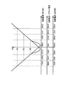
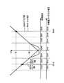
では、地絡判定用上限閾値VA以上であると判定された電圧値(比較電圧値及び補償用比較電圧値)に基づいて、正方向の直流地絡電流、若しくは逆方向の直流地絡電流であるかを判断するための原理について説明する。図4は第2の実施の形態を示す直流地絡電流検出回路1Bに関わる比較電圧値V5と直流電流値(直流地絡電流、直流地絡電流+オフセット電流)との関係を示す説明図、図5は直流地絡電流検出回路1Bにおけるオフセット電流毎の直流地絡電流と比較電圧値V5との対応関係の一例を示す説明図である。
Then, based on the voltage value (comparison voltage value and compensation comparison voltage value) determined to be equal to or higher than the ground fault determination upper limit threshold VA, the forward DC ground current or the reverse DC ground current is The principle for determining whether or not there is will be described. FIG. 4 is an explanatory diagram showing a relationship between a comparison voltage value V5 and a DC current value (DC ground fault current, DC ground fault current + offset current) related to the DC ground fault
図4及び図5に示すように、例えばZCT10には+60mAのオフセット電流、補償用ZCT10Bには−60mAのオフセット電流が流れているものとする。
As shown in FIGS. 4 and 5, for example, it is assumed that an offset current of +60 mA flows through the
さらにZCT10及び補償用ZCT10Bに+30mAの直流地絡電流が発生したとすると、図4及び図5に示すように、ZCT10には、+30mAの直流地絡電流と+60mAのオフセット電流との合計+90mAの電流が流れ、補償用ZCT10Bには、+30mAの直流地絡電流と−60mAのオフセット電流との合計−30mAの電流が流れたことになる。
Further, assuming that a DC ground fault current of +30 mA is generated in the
比較電圧値生成回路13は、ZCT10のインピーダンス変化に応じてZCT10及び分圧抵抗間で分圧された電圧値V2に基づいて比較電圧値V5を生成する。尚、この際の比較電圧値V5は、図4に示すように地絡判定用上限閾値VA(直流地絡電流+オフセット電流が90mAとなる)と同じ値となる。
The comparison voltage
また、補償用比較電圧値生成回路13Bは、補償用ZCT10Bのインピーダンス変化に応じて補償用ZCT10B及び補償用分圧抵抗12B間で分圧された電圧値V2に基づいて補償用比較電圧値V5を生成する。尚、この際の補償用比較電圧値V5は、図4に示すように地絡判定用上限閾値VB(直流地絡電流+オフセット電流が−30mAとなる)と同じ値となる。
Further, the compensation comparison voltage
つまり、ZCT10及び補償用ZCT10Bに同一の+30mAの直流地絡電流が流れているにも関わらず、比較電圧値V5は地絡判定用上限閾値VA以上、補償用比較電圧値V5は地絡判定用下限閾値VB以下と、これら比較電圧値及び補償用比較電圧値は異なる値となる。
That is, although the same +30 mA DC ground fault current flows through the
そこで、実際の直流地絡電流は30mAであることに着目すると、地絡判定用閾値VA以上と判定された比較電圧値V5が正しいということが解る。 Therefore, focusing on the fact that the actual DC ground fault current is 30 mA, it can be seen that the comparison voltage value V5 determined to be equal to or higher than the ground fault determination threshold VA is correct.
また、同様に、−30mAの直流地絡電流が流れた場合、ZCT10には、オフセット電流+直流地絡電流の合計+30mAの電流が流れ、補償用ZCT10Bには、オフセット電流+直流地絡電流の合計−90mAの電流が流れる。
Similarly, when a DC ground fault current of −30 mA flows, a total current of offset current + DC ground fault current + 30 mA flows in ZCT10, and offset current + DC ground fault current flows in
つまり、比較電圧値生成回路13では、図4に示すように、地絡判定用下限閾値VB以下の比較電圧値V5が生成され、補償用比較電圧生成回路13Bでは、地絡判定用上限閾値VA以上の補償用比較電圧値V5が生成されることになる。
That is, as shown in FIG. 4, the comparison voltage
そこで、実際の直流地絡電流が−30mAであることに着目すると、地絡判定用閾値VA以上と判定された補償用比較電圧値V5が正しいということが解る。 Therefore, when attention is paid to the fact that the actual DC ground fault current is −30 mA, it is understood that the compensation comparison voltage value V5 determined to be equal to or higher than the ground fault determination threshold value VA is correct.
従って、比較電圧値及び補償用比較電圧値の内、比較電圧値V5が地絡判定用上限閾値VA以上であると判定されると、正方向の直流地絡電流が発生したものと判断し、補償用比較電圧値V5が地絡判定用上限閾値VA以上であると判定されると、逆方向の直流地絡電流が発生したものと判断することにした。 Therefore, when it is determined that the comparison voltage value V5 is equal to or greater than the ground fault determination upper limit threshold VA among the comparison voltage value and the compensation comparison voltage value, it is determined that a positive DC ground fault current has occurred, When it is determined that the compensation comparison voltage value V5 is equal to or greater than the ground fault determination upper limit threshold value VA, it is determined that a DC ground fault current in the reverse direction has occurred.
尚、請求項2記載の直流電流検出回路及び請求項6記載の直流地絡電流検出回路は直流地絡電流検出回路1B、制御回路は制御回路14Bに相当するものである。
The DC current detection circuit according to claim 2 and the DC ground fault current detection circuit according to claim 6 correspond to the DC ground fault
次に第2の実施の形態を示す直流地絡電流検出回路1Bの動作について説明する。
Next, the operation of the DC ground fault
ZCT10には、+60mAのオフセット電流が流れ、補償用ZCT10Bには、−60mAのオフセット電流が流れる。
An offset current of +60 mA flows through the
比較電圧値生成回路13は、ZCT10及び分圧抵抗12間で分圧された電圧値V2に基づいて比較電圧値V5を生成すると、この比較電圧値V5を正方向直流地絡判定回路31に伝送する。
When the comparison voltage
また、補償用比較電圧値生成回路13Bは、補償用ZCT10B及び補償用分圧抵抗12B間で分圧された電圧値V2に基づいて補償用比較電圧値V5を生成すると、この補償用比較電圧値V5を逆方向直流地絡判定回路32に伝送する。
Further, when the compensation comparison voltage
正方向直流地絡判定回路31は、比較電圧値V5が地絡判定用上限閾値VA以上であるか否かを判定し、この判定結果を直流地絡判定回路33に伝送する。
The positive-direction DC ground
逆方向直流地絡判定回路32は、補償用比較電圧値V5が地絡判定用上限閾値VA以上であるか否かを判定し、この判定結果を直流地絡判定回路33に伝送する。
The reverse DC ground
直流地絡判定回路33は、正方向直流地絡判定回路31にて比較電圧値V5が地絡判定用上限閾値VA以上であると判定されると、正方向の直流地絡電流が発生したものと判断すると共に、逆方向直流地絡判定回路32にて補償用比較電圧値V5が地絡判定用上限閾値VA以上であると判定されると、逆方向の直流地絡電流が発生したものと判断する。
The DC ground fault determination circuit 33 generates a positive DC ground fault current when the positive DC ground
第2の実施の形態によれば、ZCT10にて検出するオフセット電流とは逆方向のオフセット電流が検出されるようにオフセット用電線21及び電源線110A,110Bを挿通すると共に、補償用分圧抵抗12Bと直列に接続する、ZCT10と同一特性の補償用ZCT10Bと、この補償用ZCT10Bのインピーダンス変化に応じて補償用ZCT10B及び補償用分圧抵抗12B間で分圧される電圧値に基づいて補償用比較電圧値を生成する補償用比較電圧値生成回路13Bとを有し、比較電圧値生成回路13にて生成した比較電圧値が地絡判定用上限閾値VA以上であると判定されると、正方向の直流地絡電流が発生したものと判断すると共に、補償用比較電圧値生成回路13Bにて生成した補償用比較電圧値が地絡判定用上限閾値VA以上であると判定されると、逆方向の直流地絡電流が発生したものと判断するようにしたので、ZCT10のヒステリシス特性の影響を受けることなく、直流地絡電流の発生の有無を正確に検出することができることはもちろんのこと、直流地絡電流が正方向又は逆方向に急峻に発生したとしても、この直流地絡電流が正方向の直流地絡電流であるか、又は逆方向の直流地絡電流であるかを正確に検出することができる。
According to the second embodiment, the offset
尚、上記第2の実施の形態においては、比較電圧値が地絡判定用上限閾値VA以上であると判定されると、正方向の直流地絡電流が発生したものと判断すると共に、補償用比較電圧値が地絡判定用上限閾値VA以上であると判定されると、逆方向の直流地絡電流が発生したものと判断する直流地絡電流検出回路1Bについて説明したが、正方向及び逆方向の直流電流値を検出する直流電流検出回路にも適用可能であることは言うまでもなく、この場合には、比較電圧値に基づいて正方向の直流電流値を算出すると共に、補償用比較電圧値に基づいて逆方向の直流電流値を算出し、比較電圧値が補償用比較電圧値よりも高いと判定されると、正方向の直流電流値を現在の直流電流値として検出すると共に、補償用比較電圧値が比較電圧値よりも高いと判定されると、前記逆方向の直流電流値を前記現在の直流電流値として検出するようにすれば、ZCT10のヒステリシス特性の影響を受けることなく、正方向又は逆方向の現在の直流電流値を正確に検出することができる。
In the second embodiment, when it is determined that the comparison voltage value is equal to or greater than the ground fault determination upper limit threshold VA, it is determined that a positive DC ground fault current has occurred, and the compensation voltage value is compensated. The DC ground fault
(実施の形態3)
また、直流地絡電流が急峻に発生したとしても、直流地絡電流が正方向の直流地絡電流、若しくは逆方向の直流地絡電流であるかを正確に検出することができる、第3の実施の形態を示す直流地絡電流検出回路について説明する。図6は第3の実施の形態を示す直流地絡電流検出回路内部の概略構成を示すブロック図である。尚、図1に示す直流地絡電流検出回路1Aと同一のものには、同一符号を付すことで、その重複する構成及び動作の説明については省略する。
(Embodiment 3)
Further, even if the DC ground fault current is sharply generated, it is possible to accurately detect whether the DC ground fault current is a forward DC ground fault current or a reverse DC ground fault current. A DC ground fault current detection circuit showing the embodiment will be described. FIG. 6 is a block diagram showing a schematic configuration inside the DC ground fault current detection circuit showing the third embodiment. The same components as those of the DC ground fault
図6に示す直流地絡電流検出回路1Cは、電源線110A,110B及びオフセット用電線21を挿通するZCT10、発振回路11、比較電圧値生成回路13及び地絡判定用閾値メモリ23の他に、所定周期毎に電流値の異なるオフセット電流を発生するオフセット電流発生回路22Cと、比較電圧値V5が地絡判定用上限閾値VA以上であると判定されると、又は、比較電圧値V5が地絡判定用下限閾値VB以下であると判定されると、電源線110A,110Bに直流地絡電流が発生したものと判断する制御回路14Cとを有している。
The DC ground fault
オフセット電流発生回路22Cは、所定周期、例えば20ms毎に、+58mAのオフセット電流と+60mAのオフセット電流とを交互に発生出力するものである。
The offset
制御回路14Cは、電源線110A,110Bに関わる直流地絡電流が発生したものと判断されると、この直流地絡電流発生判断時に関わるオフセット電流値と比較電圧値V5との変動推移を監視する変動推移監視回路41と、この変動推移監視回路41の監視結果に基づいて、正方向の直流地絡電流又は逆方向の直流地絡電流が発生したものであるかを判断する直流地絡判定回路42とを有している。
When it is determined that the DC ground fault current related to the
直流地絡判定回路42は、変動推移監視回路41の監視結果に基づいて、オフセット電流値が高くなると、比較電圧値V5も高くなる変動推移を検出すると、正方向の直流地絡電流が発生したものと判断すると共に、オフセット電流値が高くなると、比較電圧値V5が低くなる変動推移を検出すると、逆方向の直流地絡電流が発生したものと判断するものである。
When the DC ground
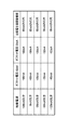
では、これら比較電圧値V5及びオフセット電流値に基づく変動推移について説明する。図7は第3の実施の形態を示す直流地絡電流検出回路1Cに関わる比較電圧値V5及び直流電流値(直流地絡電流、直流地絡電流+オフセット電流)との関係を示す説明図、図8は直流地絡電流検出回路1Cに関わる直流地絡電流と変動推移との対応関係の一例を示す説明図である。
Now, a change transition based on the comparison voltage value V5 and the offset current value will be described. FIG. 7 is an explanatory diagram illustrating a relationship between a comparison voltage value V5 and a DC current value (DC ground fault current, DC ground fault current + offset current) related to the DC ground fault
例えば+30mAの直流地絡電流が流れた場合、図7及び図8に示すように、+60mAのオフセット電流が流れると、+90mAの直流地絡電流+オフセット電流が流れる。また、+58mAのオフセット電流が流れると、図7及び図8に示すように、+88mAの直流地絡電流+オフセット電流が流れる。 For example, when a +30 mA DC ground fault current flows, as shown in FIGS. 7 and 8, if a +60 mA offset current flows, a +90 mA DC ground fault current + offset current flows. When an offset current of +58 mA flows, a +88 mA DC ground fault current + offset current flows as shown in FIGS.
この際、+60mAのオフセット電流と+58mAのオフセット電流との比較電圧値V5に着目すると、+60mAのオフセット電流が流れた時の比較電圧値V5が+58mAのオフセット電流が流れた時の比較電圧値V5よりも高くなることが解る。 At this time, focusing on the comparison voltage value V5 between the offset current of +60 mA and the offset current of +58 mA, the comparison voltage value V5 when the offset current of +60 mA flows is larger than the comparison voltage value V5 when the offset current of +58 mA flows. It turns out that it becomes high.
また、0mAの直流地絡電流が流れた場合、図7及び図8に示すように、+60mAのオフセット電流が流れた時の比較電圧値V5が+58mAのオフセット電流が流れた時の比較電圧値V5よりも高くなることが解る。 When a DC ground fault current of 0 mA flows, as shown in FIGS. 7 and 8, the comparison voltage value V5 when the offset current of +58 mA flows is the comparison voltage value V5 when the offset current of +60 mA flows. It turns out that it becomes higher than.
このように+60mAのオフセット電流が流れた時の比較電圧値V5が+58mAのオフセット電流が流れた時の比較電圧値V5よりも高くなる変動推移を、オフセット電流値が高くなると比較電圧値V5が高くなる変動推移としている。 As described above, when the offset current value is increased, the comparison voltage value V5 when the offset current of +60 mA flows is higher than the comparison voltage value V5 when the offset current of +58 mA flows. The change is as follows.
また、−120mAの直流地絡電流が流れた場合、+60mAのオフセット電流が流れると、図7及び図8に示すように、−60mAの直流地絡電流+オフセット電流が流れる。また、+58mAのオフセット電流が流れると、図7及び図8に示すように、−62mAの直流地絡電流+オフセット電流が流れる。 Further, when a −120 mA DC ground fault current flows, a +60 mA offset current flows, as shown in FIGS. 7 and 8, a −60 mA DC ground fault current + offset current flows. Further, when an offset current of +58 mA flows, as shown in FIGS. 7 and 8, a DC ground fault current of +62 mA and an offset current flow.
この際、+60mAのオフセット電流と+58mAのオフセット電流との比較電圧値V5に着目すると、+58mAのオフセット電流が流れた時の比較電圧値V5が+60mAのオフセット電流が流れた時の比較電圧値V5よりも高くなることが解る。 At this time, focusing on the comparison voltage value V5 between the offset current of +60 mA and the offset current of +58 mA, the comparison voltage value V5 when the offset current of +58 mA flows is larger than the comparison voltage value V5 when the offset current of +60 mA flows. It turns out that it becomes high.
同様に、−90mAの直流地絡電流が流れた場合、+58mAのオフセット電流が流れた時の比較電圧値V5が+60mAのオフセット電流が流れた時の比較電圧値V5よりも高くなることが解る。 Similarly, when a DC ground fault current of −90 mA flows, the comparison voltage value V5 when the offset current of +58 mA flows is higher than the comparison voltage value V5 when the offset current of +60 mA flows.
このように+60mAのオフセット電流が流れた時の比較電圧値V5が+58mAのオフセット電流が流れた時の比較電圧値V5よりも低くなる変動推移を、オフセット電流値が高くなると比較電圧値V5が低くなる変動推移としている。 In this way, the variation voltage V5 when the offset current of +60 mA flows is lower than the comparison voltage value V5 when the offset current of +58 mA flows, and the comparison voltage value V5 decreases as the offset current value increases. The change is as follows.
尚、請求項3記載の直流電流検出回路及び請求項6記載の直流地絡電流検出回路は直流地絡電流検出回路1C、オフセット電流検出回路はオフセット電流検出回路22C、制御回路は制御回路14Cに相当するものである。
The DC current detection circuit according to claim 3 and the DC ground fault current detection circuit according to claim 6 are connected to the DC ground fault
次に第3の実施の形態を示す直流地絡電流検出回路1Cの動作について説明する。
Next, the operation of the DC ground fault
制御回路14Cの変動推移監視回路41は、直流地絡電流が発生したものと判断されると、この直流地絡電流発生判断時の+58mAのオフセット電流が流れた時の比較電圧値V5と+60mAのオフセット電流が流れた時の比較電圧値V5との変動推移を監視する。
When it is determined that a DC ground fault current has occurred, the fluctuation
直流地絡判定回路42は、変動推移監視回路41からの監視結果に基づいて、オフセット電流値が高くなると、比較電圧値V5が高くなるような変動推移、すなわち、+60mAのオフセット電流が流れた時の比較電圧値V5が+58mAのオフセット電流が流れた時の比較電圧値V5よりも高くなる変動推移を検出すると、正方向の直流地絡電流が発生したものと判断する。
Based on the monitoring result from the fluctuation
また、直流地絡判定回路42は、変動推移監視回路41からの監視結果に基づいて、オフセット電流値が高くなると、比較電圧値V5が低くなるような変動推移、すなわち、+60mAのオフセット電流が流れた時の比較電圧値V5が+58mAのオフセット電流が流れた時の比較電圧値V5よりも低くなる変動推移を検出すると、逆方向の直流地絡電流が発生したものと判断する。
Further, the DC ground
第3の実施の形態によれば、所定周期毎に電流値の異なるオフセット電流を流し、電源線110A,110Bに関わる直流地絡電流が発生したものと判断されると、この直流地絡電流発生判断時に関わるオフセット電流値と比較電圧値V5との変動推移を監視し、オフセット電流値が高くなると、比較電圧値V5も高くなる変動推移を検出すると、正方向の直流地絡電流が発生したものと判断すると共に、オフセット電流値が高くなると、比較電圧値が低くなる変動推移を検出すると、逆方向の直流地絡電流が発生したものと判断するようにしたので、ZCT10のヒステリシス特性の影響を受けることなく、直流地絡電流の発生の有無を正確に検出することができることはもちろんのこと、補償用ZCT、補償用分圧抵抗や補償用比較電圧値生成回路を設けなくても、直流地絡電流が正方向又は逆方向に急峻に発生したとしても、この直流地絡電流が正方向の直流地絡電流、又は逆方向の直流地絡電流であるかを正確に検出することができる。
According to the third embodiment, when it is determined that a DC ground fault current relating to the
尚、上記第3の実施の形態においては、オフセット電流値と比較電圧値V5との変動推移に基づいて正方向の直流地絡電流、若しくは逆方向の直流地絡電流であるかを判断する直流地絡電流検出回路1Cについて説明したが、正方向及び逆方向の直流電流値を検出する直流電流検出回路にも適用可能であることは言うまでもなく、比較電圧値V5に基づいて正方向の直流電流値及び逆方向の直流電流値を算出すると、電流値検出時に関わるオフセット電流値と比較電圧値V5との変動推移を監視し、オフセット電流値が高くなると、比較電圧値V5も高くなる変動推移を検出すると、前記正方向の直流電流値を前記現在の直流電流値として検出すると共に、オフセット電流値が高くなると、比較電圧値が低くなる変動推移を検出すると、逆方向の直流電流値を現在の直流電流値として検出するようにすれば、補償用ZCT、補償用分圧抵抗や補償用比較電圧値生成回路を設けなくても、ZCT10のヒステリシス特性の影響を受けることなく、現在の直流電流値を正確に検出することができることはもちろんのこと、補償用ZCT、補償用分圧抵抗や補償用比較電圧値生成回路を設けなくても、現在の直流電流値が正方向又は逆方向に急峻に変化としても、同直流電流値が正方向の直流電流値、若しくは逆方向の直流電流値であるかを正確に検出することができる。
In the third embodiment, a direct current for determining whether the current is a forward DC ground fault current or a reverse DC ground fault current based on a change transition of the offset current value and the comparison voltage value V5. The ground fault
(実施の形態4)
次に第4の実施の形態を示す直流地絡電流検出回路について説明する。図9は第4の実施の形態を示す直流地絡電流検出回路内部の概略構成を示すブロック図である。尚、図1に示す直流地絡電流検出回路1Aと同一のものには同一符号を付すことで、その重複する構成及び動作の説明については省略する。
(Embodiment 4)
Next, a DC ground fault current detection circuit showing a fourth embodiment will be described. FIG. 9 is a block diagram showing a schematic configuration inside the DC ground fault current detection circuit showing the fourth embodiment. In addition, the same code | symbol is attached | subjected to the same thing as 1 A of DC ground fault current detection circuits shown in FIG. 1, and the description of the overlapping structure and operation | movement is abbreviate | omitted.
図9に示す直流地絡電流検出回路1Dは、電源線110A、110Bを挿通するZCT10、発振回路11、比較電圧値生成回路13及び地絡判定用閾値メモリ23を有し、ZCT10のヒステリシス特性の影響を受けて、比較電圧値V5に基づく正確な直流地絡電流の直流電流値の検出を困難とする電流範囲を、比較電圧値V5に基づく直流電流値の検出を可能とする電流検出可能範囲にシフトすべく、ZCT10に対して、電源線110A,110Bを複数回挿通するように構成した。
The DC ground fault current detection circuit 1D shown in FIG. 9 has a
つまり、ZCT10に挿通する電源線110A,110Bの挿通回数分だけ直流地絡電流が加算されることになるため、この加算分だけ、電流検出可能範囲にシフトされるとことになる。
That is, since the DC ground fault current is added by the number of insertions of the
尚、請求項4記載の直流電流検出回路及び請求項8記載の直流地絡電流検出回路は直流地絡電流検出回路1Dに相当するものである。 The DC current detection circuit according to claim 4 and the DC ground fault current detection circuit according to claim 8 correspond to the DC ground fault current detection circuit 1D.
次に第4の実施の形態を示す直流地絡電流検出回路1Dの動作について説明する。 Next, the operation of the DC ground fault current detection circuit 1D showing the fourth embodiment will be described.
ZCT10では、電源線110A、110Bが3回挿通された場合、例えば電源線110A,110Bに+20mAの直流地絡電流が流れると、ZCT10では、+60mAの電流が流れたのと同じになる。
In ZCT10, when the
比較電圧値生成回路13では、ZCT10のインピーダンス変化に応じてZCT10及び分圧抵抗12間で分圧された電圧値に基づいて比較電圧値V5を生成することになる。
In the comparison voltage
制御回路14では、比較電圧値V5が地絡判定用上限閾値VA以上であると判定されると、又は、比較電圧値V5が地絡判定用下限閾値VB以下であると判定されると、直流地絡電流が発生したものと判断する。
In the
第4の実施の形態によれば、ZCT10のヒステリシス特性の影響を受けて、比較電圧値V5に基づく正確な直流地絡電流の直流電流値の検出を困難とする電流範囲を、比較電圧値V5に基づく直流電流値の検出を可能とする電流検出可能範囲にシフトすべく、ZCT10に対して、電源線110A、110Bを複数回挿通するように構成したので、オフセット電流発生回路等の別回路を設けなくても、その電源線110A,110Bの挿通回数を変えるだけで、ZCT10のヒステリシス特性の影響を受けることなく、直流地絡電流の発生の有無を正確に検出することができる。
According to the fourth embodiment, a current range in which it is difficult to accurately detect the DC current value of the DC ground fault current based on the comparison voltage value V5 under the influence of the hysteresis characteristic of the
尚、第4の実施の形態においては、オフセット電流発生回路を用いることなく、電源線110A,110BをZCT10に複数回挿通することで、ZCT10のヒステリシス特性の影響を受ける電流範囲を電流検出可能範囲にシフトし、この電流検出可能範囲内で比較電圧値V5に基づく直流地絡電流の発生の有無を検出することができる直流地絡電流検出回路1Dについて説明したが、現在の直流電流値を検出する直流電流検出回路にも適用可能であることは言うまでもなく、この場合、ZCT10のヒステリシス特性の影響を受けて、比較電圧値V5に基づく正確な直流電流値の検出を困難とする電流範囲での、比較電圧値V5に基づく直流電流値の検出を可能とすべく、ZCT10に対して、電源線110A,110Bを複数回挿通するように構成することで、同電流範囲を挿通回数の電流分だけシフトすることで、比較電圧値V5に基づく電流値検出を可能とし、この電流値及び挿通回数の電流分の電流値に基づいて直流電流値を算出し、この直流電流値を現在の直流電流値として検出するようにすれば、オフセット電流発生回路等の別回路を設けなくても、その電源線110A,110Bの挿通回数を変えるだけで、ZCT10のヒステリシス特性の影響を受けることなく、正確に現在の直流電流値を検出することができる。
In the fourth embodiment, the current range affected by the hysteresis characteristics of the
本発明の直流電流検出回路は、比較電圧値に基づいて直流電流値を検出することができない微小電流範囲内であっても、現在の直流電流値を正確に検出することができる、ZCTを使用した直流電流検出回路に有用である。 The DC current detection circuit of the present invention uses the ZCT, which can accurately detect the current DC current value even within a minute current range where the DC current value cannot be detected based on the comparison voltage value. This is useful for a DC current detection circuit.
また、本発明の直流地絡電流検出回路は、比較電圧値に基づく直流地絡電流の発生の有無を検出することができない微小電流範囲内であっても、正確に直流地絡電流の発生有無を検出することができる、ZCTを使用した直流地絡電流検出回路に有用である。 In addition, the DC ground fault current detection circuit of the present invention accurately detects whether or not a DC ground fault current is generated even within a minute current range in which the presence or absence of a DC ground fault current based on the comparison voltage value cannot be detected. This is useful for a DC ground fault current detection circuit using ZCT.
1A、1B,1C,1D 直流地絡電流検出回路(直流電流検出回路)
10 ZCT(零相変流器)
10B 補償用ZCT(補償用零相変流器)
12 分圧抵抗
12B 補償用分圧抵抗
13 比較電圧値生成回路
13B 補償用比較電圧値生成回路
14、14B、14C 制御回路
21 オフセット用電線
22、22C オフセット電流発生回路
23 地絡判定用閾値メモリ
31 正方向直流地絡判定回路(現在直流値検出回路、直流地絡判定回路)
32 逆方向直流地絡判定回路(現在直流値検出回路、直流地絡判定回路)
33、42 直流地絡判定回路
41 変動推移監視回路
110A,110B 電源線
1A, 1B, 1C, 1D DC ground fault current detection circuit (DC current detection circuit)
10 ZCT (Zero Phase Current Transformer)
10B ZCT for compensation (zero phase current transformer for compensation)
12
32 Reverse DC ground fault judgment circuit (current DC value detection circuit, DC ground fault judgment circuit)
33, 42 DC ground
Claims (4)
前記零相変流器に挿通されるオフセット用電線と、
前記零相変流器のヒステリシス特性の影響を受けて、前記比較電圧値に基づく正確な直流電流値の検出を困難とする電流範囲での、前記比較電圧値に基づく直流電流値の検出を可能とすべく、前記オフセット用電線にオフセット電流を発生するオフセット電流発生回路と、
前記電源線を挿通すると共に、前記零相変流器にて検出するオフセット電流とは逆方向のオフセット電流が検出されるように、前記オフセット用電線を挿通する、前記零相変流器と同一特性の補償用零相変流器と、
この補償用零相変流器に直列に接続され、前記分圧抵抗と同一特性の補償用分圧抵抗と、
前記補償用零相変流器のインピーダンス変化に応じて前記補償用零相変流器及び前記補償用分圧抵抗間で分圧される電圧値に基づいて補償用比較電圧値を生成する補償用比較電圧値生成回路とを有して構成し、
前記制御回路が、
前記比較電圧値生成回路にて生成した比較電圧値に基づいて正方向の電流値を検出し、この正方向の電流値及び前記オフセット電流分の電流値に基づいて正方向の直流電流値を算出すると共に、前記補償用比較電圧値生成回路にて生成した補償用比較電圧値に基づいて逆方向の電流値を検出し、この逆方向の電流値及び前記オフセット電流分の電流値に基づいて逆方向の直流電流値を算出する直流電流値算出回路と、
前記正方向の直流電流値及び前記逆方向の直流電流値の内、前記比較電圧値が前記補償用比較電圧値よりも高いと判定されると、前記正方向の直流電流値を選択し、この正方向の直流電流値を前記現在の直流電流値として検出すると共に、前記補償用比較電圧値が前記比較電圧値よりも高いと判定されると、前記逆方向の直流電流値を選択し、この逆方向の直流電流値を前記現在の直流電流値として検出する現在直流値検出回路とを有して構成したことを特徴とする直流電流検出回路。 A zero-phase current transformer connected in series with a voltage dividing resistor that detects the current difference of each power line magnetically by inserting the power line and fluctuates the self-impedance according to the magnetic field change caused by this current difference. And a comparison voltage value generation circuit that generates a comparison voltage value based on a voltage value divided between the zero phase current transformer and the voltage dividing resistor in accordance with an impedance change of the zero phase current transformer, A direct current detection circuit having a control circuit for detecting a current direct current value based on the comparison voltage value generated by the comparison voltage value generation circuit;
An offset wire inserted through the zero-phase current transformer;
Possible to detect a DC current value based on the comparison voltage value in a current range that makes it difficult to detect an accurate DC current value based on the comparison voltage value due to the hysteresis characteristics of the zero-phase current transformer. An offset current generating circuit for generating an offset current in the offset wire;
Same as the zero-phase current transformer, which is inserted through the power supply line and through which the offset wire is inserted so that an offset current in a direction opposite to the offset current detected by the zero-phase current transformer is detected. A zero-phase current transformer for compensating characteristics;
A compensation voltage dividing resistor connected in series to the compensation zero-phase current transformer, having the same characteristics as the voltage dividing resistor,
Compensation for generating a comparison comparison voltage value based on a voltage value divided between the compensation zero-phase current transformer and the compensation voltage dividing resistor in accordance with an impedance change of the compensation zero-phase current transformer It constitutes a comparison voltage value generating circuit,
Wherein the control circuit,
A positive current value is detected based on the comparison voltage value generated by the comparison voltage value generation circuit, and a positive direct current value is calculated based on the positive current value and the current value corresponding to the offset current. In addition, a reverse current value is detected based on the compensation comparison voltage value generated by the compensation comparison voltage value generation circuit, and the reverse current value and the current value corresponding to the offset current are reversed. A direct current value calculation circuit for calculating a direct current value in the direction;
Of the direct current value in the forward direction and the direct current value in the reverse direction, if it is determined that the comparison voltage value is higher than the compensation comparison voltage value, the direct current value in the positive direction is selected, While detecting a direct current value in the forward direction as the current direct current value and determining that the compensation comparison voltage value is higher than the comparison voltage value, select the reverse direct current value, dc current detecting circuit, characterized by being configured to have a the current DC value detecting circuit for detecting a reverse DC current value said as the current of the DC current value.
前記零相変流器に挿通されるオフセット用電線と、
前記零相変流器のヒステリシス特性の影響を受けて、前記比較電圧値に基づく正確な直流電流値の検出を困難とする電流範囲での、前記比較電圧値に基づく直流電流値の検出を可能とすべく、前記オフセット用電線に所定周期毎に電流値の異なるオフセット電流を発生する機能を有するオフセット電流発生回路とを有して構成し、
前記制御回路が、
前記比較電圧値生成回路にて生成した比較電圧値に基づいて正方向の電流値及び逆方向の電流値を検出し、前記正方向の電流値及び前記オフセット電流分の電流値に基づいて正方向の直流電流値を算出すると共に、前記逆方向の電流値及び前記オフセット電流分の電流値に基づいて逆方向の直流電流値を算出する直流電流値算出回路と、
前記正方向の直流電流値及び逆方向の直流電流値を算出すると、前記電流値検出時に関わる前記オフセット電流値と前記比較電圧値との変動推移を監視する変動推移監視回路と、
この変動推移監視回路にて、前記オフセット電流値が高くなると、前記比較電圧値も高くなる変動推移を検出すると、前記正方向の直流電流値を前記現在の直流電流値として検出すると共に、前記オフセット電流値が高くなると、前記比較電圧値が低くなる変動推移を検出すると、前記逆方向の直流電流値を前記現在の直流電流値として検出する現在直流検出回路とを有して構成したことを特徴とする直流電流検出回路。 A zero-phase current transformer connected in series with a voltage dividing resistor that detects the current difference of each power line magnetically by inserting the power line and fluctuates the self-impedance according to the magnetic field change caused by this current difference. And a comparison voltage value generation circuit that generates a comparison voltage value based on a voltage value divided between the zero phase current transformer and the voltage dividing resistor in accordance with an impedance change of the zero phase current transformer, A direct current detection circuit having a control circuit for detecting a current direct current value based on the comparison voltage value generated by the comparison voltage value generation circuit;
An offset wire inserted through the zero-phase current transformer;
Possible to detect a DC current value based on the comparison voltage value in a current range that makes it difficult to detect an accurate DC current value based on the comparison voltage value due to the hysteresis characteristics of the zero-phase current transformer. in order to the make up and a offset current generating circuit which have the function of generating different offset current of the current value for each predetermined period to the offset electric wire,
Wherein the control circuit,
A forward current value and a reverse current value are detected based on the comparison voltage value generated by the comparison voltage value generation circuit, and a positive direction is determined based on the positive current value and the current value corresponding to the offset current. A DC current value calculating circuit that calculates a DC current value in the reverse direction based on the current value in the reverse direction and the current value corresponding to the offset current,
When calculating the direct current value in the forward direction and the direct current value in the reverse direction, a variation transition monitoring circuit that monitors a variation transition between the offset current value and the comparison voltage value related to the detection of the current value;
In the fluctuation transition monitoring circuit, when the fluctuation transition in which the comparison voltage value is increased when the offset current value is increased is detected, the DC current value in the positive direction is detected as the current DC current value, and the offset wherein the current value is high, when the comparison voltage value detecting variations transition becomes lower, that the direct current value of the reverse was constructed possess a current DC detection circuit for detecting said as the current value of the direct current dc current detecting circuit according to.
前記零相変流器に挿通されるオフセット用電線と、
前記零相変流器のヒステリシス特性の影響を受けて、前記比較電圧値に基づく正確な直流地絡電流の直流電流値の検出を困難とする電流範囲を、前記比較電圧値に基づく直流電流値の検出を可能とする電流検出可能範囲にシフトすべく、前記オフセット用電線にオフセット電流を発生するオフセット電流発生回路と、
前記電流検出可能範囲内の直流地絡電流発生判断に関わる直流電流値に対応した地絡判定用上限閾値及び地絡判定用下限閾値を記憶管理した地絡判定用閾値メモリと、
前記電源線を挿通すると共に、前記零相変流器にて検出するオフセット電流とは逆方向のオフセット電流が検出されるように、前記オフセット用電線を挿通する、前記零相変流器と同一特性の補償用零相変流器と、
この補償用零相変流器に直列に接続され、前記分圧抵抗と同一特性の補償用分圧抵抗と、
前記補償用零相変流器のインピーダンス変化に応じて前記補償用零相変流器及び前記補償用分圧抵抗間で分圧される電圧値に基づいて補償用比較電圧値を生成する補償用比較電圧値生成回路とを有して構成し、
前記制御回路が、
前記比較電圧値生成回路にて比較電圧値を生成し、この比較電圧値が前記地絡判定用上限閾値以上であると判定されると、前記正方向の直流地絡電流が発生したものと判断すると共に、前記補償用比較電圧値生成回路にて補償用比較電圧値を生成し、この補償用比較電圧値が前記地絡判定用上限閾値以上であると判定されると、前記逆方向の直流地絡電流が発生したものと判断する直流地絡判定回路を有して構成したことを特徴とする直流地絡電流検出回路。 A zero-phase current transformer connected in series with a voltage dividing resistor that detects the current difference of each power line magnetically by inserting the power line and fluctuates the self-impedance according to the magnetic field change caused by this current difference. And a comparison voltage value generation circuit that generates a comparison voltage value based on a voltage value divided between the zero phase current transformer and the voltage dividing resistor in accordance with an impedance change of the zero phase current transformer, A DC ground fault current detection circuit having a control circuit for detecting the presence or absence of the occurrence of a DC ground fault current related to the power supply line based on the comparison voltage value generated by the comparison voltage value generation circuit,
An offset wire inserted through the zero-phase current transformer;
Under the influence of the hysteresis characteristic of the zero-phase current transformer, a current range that makes it difficult to detect a direct current value of an accurate direct current ground fault current based on the comparison voltage value is a direct current value based on the comparison voltage value. An offset current generating circuit for generating an offset current in the offset wire to shift to a current detectable range that enables detection of
A ground fault determination threshold memory storing and managing a ground fault determination upper limit threshold value and a ground fault determination lower limit threshold value corresponding to a DC current value related to a DC ground fault current generation determination within the current detectable range;
Same as the zero-phase current transformer, which is inserted through the power supply line and through which the offset wire is inserted so that an offset current in a direction opposite to the offset current detected by the zero-phase current transformer is detected. A zero-phase current transformer for compensating characteristics;
A compensation voltage dividing resistor connected in series to the compensation zero-phase current transformer, having the same characteristics as the voltage dividing resistor,
Compensation for generating a comparison comparison voltage value based on a voltage value divided between the compensation zero-phase current transformer and the compensation voltage dividing resistor in accordance with an impedance change of the compensation zero-phase current transformer and configure have a comparison voltage value generating circuit,
Wherein the control circuit,
A comparison voltage value is generated by the comparison voltage value generation circuit, and when it is determined that the comparison voltage value is equal to or greater than the upper limit threshold for ground fault determination, it is determined that the positive DC ground fault current has occurred. In addition, the compensation comparison voltage value generation circuit generates a compensation comparison voltage value, and when the compensation comparison voltage value is determined to be equal to or higher than the ground fault determination upper limit threshold, the reverse direction direct current straight Nagarechi fault current detecting circuit, characterized in that the ground fault current is composed have a DC ground fault determining circuit which determines that occurred.
前記零相変流器に挿通されるオフセット用電線と、
前記零相変流器のヒステリシス特性の影響を受けて、前記比較電圧値に基づく正確な直流地絡電流の直流電流値の検出を困難とする電流範囲を、前記比較電圧値に基づく直流電流値の検出を可能とする電流検出可能範囲にシフトすべく、前記オフセット用電線に所定周期毎に電流値の異なるオフセット電流を発生するオフセット電流発生回路と、
前記電流検出可能範囲内の直流地絡電流発生判断に関わる直流電流値に対応した地絡判定用上限閾値及び地絡判定用下限閾値を記憶管理した地絡判定用閾値メモリとを有して構成し、
前記制御回路が、
前記電源線に関わる直流地絡電流が発生したものと判断されると、この直流地絡電流発生判断時に関わる前記オフセット電流値と前記比較電圧値との変動推移を監視する変動推移監視回路と、
この変動推移監視回路にて、前記オフセット電流値が高くなると、前記比較電圧値も高くなる変動推移を検出すると、前記正方向の直流地絡電流が発生したものと判断すると共に、前記オフセット電流値が高くなると、前記比較電圧値が低くなる変動推移を検出すると、前記逆方向の直流地絡電流が発生したものと判断する直流地絡判定回路とを有して構成したことを特徴とする直流地絡電流検出回路。 A zero-phase current transformer connected in series with a voltage dividing resistor that detects the current difference of each power line magnetically by inserting the power line and fluctuates the self-impedance according to the magnetic field change caused by this current difference. And a comparison voltage value generation circuit that generates a comparison voltage value based on a voltage value divided between the zero phase current transformer and the voltage dividing resistor in accordance with an impedance change of the zero phase current transformer, A DC ground fault current detection circuit having a control circuit for detecting the presence or absence of the occurrence of a DC ground fault current related to the power supply line based on the comparison voltage value generated by the comparison voltage value generation circuit,
An offset wire inserted through the zero-phase current transformer;
Under the influence of the hysteresis characteristic of the zero-phase current transformer, a current range that makes it difficult to detect a direct current value of an accurate direct current ground fault current based on the comparison voltage value is a direct current value based on the comparison voltage value. An offset current generating circuit for generating an offset current having a different current value for each predetermined period in the offset wire to shift to a current detectable range that enables detection of
A ground fault determination threshold memory that stores and manages a ground fault determination upper limit threshold and a ground fault determination lower limit threshold corresponding to a DC current value related to the determination of a DC ground fault current occurrence within the current detectable range. And
Wherein the control circuit,
When it is determined that a DC ground fault current related to the power supply line has occurred, a change transition monitoring circuit that monitors a change transition of the offset current value and the comparison voltage value related to the determination of the DC ground fault current,
When the fluctuation transition monitoring circuit detects a fluctuation transition in which the comparison voltage value also increases when the offset current value increases, it is determined that the positive DC ground fault current has occurred, and the offset current value When increases, when the comparison voltage value detecting variations transition be lower, straight, characterized in that the reverse DC ground fault current is constituted by perforated a DC ground fault determining circuit which determines that occurred Current ground fault current detection circuit.
Priority Applications (4)
| Application Number | Priority Date | Filing Date | Title |
|---|---|---|---|
| JP2003290269A JP3966251B2 (en) | 2003-08-08 | 2003-08-08 | DC current detection circuit and DC ground fault current detection circuit |
| EP04017130A EP1505398A1 (en) | 2003-08-08 | 2004-07-20 | Direct current detection circuit |
| US10/901,249 US7176673B2 (en) | 2003-08-08 | 2004-07-27 | Direct current detection circuit |
| CNA2004100558739A CN1580796A (en) | 2003-08-08 | 2004-08-05 | DC. detection circuit and DC. earthing current detection circuit |
Applications Claiming Priority (1)
| Application Number | Priority Date | Filing Date | Title |
|---|---|---|---|
| JP2003290269A JP3966251B2 (en) | 2003-08-08 | 2003-08-08 | DC current detection circuit and DC ground fault current detection circuit |
Publications (2)
| Publication Number | Publication Date |
|---|---|
| JP2005065382A JP2005065382A (en) | 2005-03-10 |
| JP3966251B2 true JP3966251B2 (en) | 2007-08-29 |
Family
ID=33550078
Family Applications (1)
| Application Number | Title | Priority Date | Filing Date |
|---|---|---|---|
| JP2003290269A Expired - Lifetime JP3966251B2 (en) | 2003-08-08 | 2003-08-08 | DC current detection circuit and DC ground fault current detection circuit |
Country Status (4)
| Country | Link |
|---|---|
| US (1) | US7176673B2 (en) |
| EP (1) | EP1505398A1 (en) |
| JP (1) | JP3966251B2 (en) |
| CN (1) | CN1580796A (en) |
Families Citing this family (24)
| Publication number | Priority date | Publication date | Assignee | Title |
|---|---|---|---|---|
| DE102005007378A1 (en) * | 2005-02-17 | 2006-08-24 | Siemens Ag | Device for inductive DC detection |
| JP4986114B2 (en) * | 2006-04-17 | 2012-07-25 | ルネサスエレクトロニクス株式会社 | Semiconductor integrated circuit and design method of semiconductor integrated circuit |
| WO2008026276A1 (en) | 2006-08-31 | 2008-03-06 | Mitsubishi Electric Corporation | Zero-phase current detecting apparatus |
| CN101452034B (en) * | 2007-11-30 | 2011-08-10 | 上海市电力公司 | Portable intelligent DC earthing searching instrument |
| AU2010329183B2 (en) * | 2009-12-07 | 2014-03-06 | Kabushiki Kaisha Toshiba | Photovoltaic power generation system |
| CN101776723B (en) * | 2009-12-25 | 2013-07-24 | 上海希明电气技术有限公司 | Method for detecting earth fault of direct current system by utilizing frequency deviation method |
| JP5295996B2 (en) * | 2010-03-10 | 2013-09-18 | 株式会社東芝 | Solar power system |
| EP2372857B1 (en) * | 2010-03-31 | 2015-10-07 | SMA Solar Technology AG | Determination of the proportion of differential current made up of faulty current |
| KR101077768B1 (en) * | 2010-04-30 | 2011-10-27 | 엘에스산전 주식회사 | Apparatus for fault current supervision of power system |
| DE102011002756A1 (en) | 2011-01-17 | 2012-07-19 | Sunways Ag Photovoltaic Technology | Current measuring device for detecting a current, solar inverters and method for detecting a current |
| JP5817316B2 (en) * | 2011-08-11 | 2015-11-18 | 富士電機機器制御株式会社 | Earth leakage breaker |
| JP6362837B2 (en) * | 2012-08-29 | 2018-07-25 | 京セラ株式会社 | Zero-phase current transformer, ground fault current detection device, power conditioner, and zero-phase current transformer failure detection method |
| CN102866289B (en) * | 2012-09-05 | 2014-10-29 | 山东康威通信技术股份有限公司 | Power cable sheath grounding current fault analysis method |
| US9025298B2 (en) * | 2012-10-22 | 2015-05-05 | Eaton Corporation | Electrical switching apparatus including transductor circuit and alternating current electronic trip circuit |
| EP2796886B1 (en) | 2013-04-23 | 2017-09-06 | Technische Universität Graz | Circuit assembly for locating of insulation faults |
| CN103792444B (en) * | 2013-08-20 | 2016-12-28 | 深圳市金霆科技有限公司 | Direct-current remote feeding power input grounding testing circuit and detection method thereof |
| CN103645418A (en) * | 2013-12-04 | 2014-03-19 | 国家电网公司 | Earth fault line selector for transformer station direct current system |
| CN103995208A (en) * | 2014-03-31 | 2014-08-20 | 国网上海市电力公司 | Direct current leakage monitoring and alarming device |
| KR101803132B1 (en) * | 2014-04-28 | 2017-11-29 | 엘에스산전 주식회사 | Apparatus for Monitoring Residual Current of Transformer-less PV Inverter |
| CN104459291A (en) * | 2014-12-15 | 2015-03-25 | 南车株洲电力机车有限公司 | Method and system for detecting AC signals of specific frequency |
| CN105044549B (en) * | 2015-04-14 | 2018-04-20 | 广西电网有限责任公司电力科学研究院 | A kind of direct current grounding trouble shooting method with self compensation electric current |
| JP6429153B2 (en) * | 2015-04-22 | 2018-11-28 | パナソニックIpマネジメント株式会社 | Shut-off device |
| CA2988618A1 (en) * | 2015-06-16 | 2016-12-22 | General Electric Technology Gmbh | Methods and systems for open-phase detection in power transformers |
| FR3050034B1 (en) * | 2016-04-12 | 2019-08-02 | Sagemcom Energy & Telecom Sas | METHOD FOR DETECTING A FAULT IN AN ELECTRIC ENERGY METER COMPRISING A CUTTING MEMBER |
Family Cites Families (11)
| Publication number | Priority date | Publication date | Assignee | Title |
|---|---|---|---|---|
| US4280162A (en) * | 1977-08-04 | 1981-07-21 | North American Philips Corporation | Ground fault circuit interrupter |
| US4289946A (en) * | 1978-05-15 | 1981-09-15 | Olin Corporation | Electromagnetic casting apparatus |
| US4280163A (en) * | 1979-03-05 | 1981-07-21 | Homexx International Corp. | Electronic lock |
| US4320433A (en) * | 1980-03-21 | 1982-03-16 | Fuji Electric Co., Ltd. | Earth-leakage-current circuit breaker system |
| US4415896A (en) * | 1981-06-09 | 1983-11-15 | Adec, Inc. | Computer controlled energy monitoring system |
| US4933633A (en) * | 1981-06-09 | 1990-06-12 | Adec, Inc. | Computer controlled energy monitoring system |
| GB2251741A (en) * | 1991-01-09 | 1992-07-15 | Wellong Trading Ltd | Rapid response ground fault circuit interrupter |
| US5537029A (en) * | 1992-02-21 | 1996-07-16 | Abb Power T&D Company Inc. | Method and apparatus for electronic meter testing |
| JP3286446B2 (en) * | 1993-12-29 | 2002-05-27 | 住友特殊金属株式会社 | DC current sensor |
| US5856902A (en) * | 1996-07-09 | 1999-01-05 | Fuji Electric Co., Ltd. | Earth leakage breaker |
| US6134126A (en) * | 1998-09-08 | 2000-10-17 | Kabushiki Kaisha Toshiba | Power conversion system |
-
2003
- 2003-08-08 JP JP2003290269A patent/JP3966251B2/en not_active Expired - Lifetime
-
2004
- 2004-07-20 EP EP04017130A patent/EP1505398A1/en not_active Withdrawn
- 2004-07-27 US US10/901,249 patent/US7176673B2/en active Active
- 2004-08-05 CN CNA2004100558739A patent/CN1580796A/en active Pending
Also Published As
| Publication number | Publication date |
|---|---|
| US7176673B2 (en) | 2007-02-13 |
| EP1505398A1 (en) | 2005-02-09 |
| JP2005065382A (en) | 2005-03-10 |
| US20050030005A1 (en) | 2005-02-10 |
| CN1580796A (en) | 2005-02-16 |
Similar Documents
| Publication | Publication Date | Title |
|---|---|---|
| JP3966251B2 (en) | DC current detection circuit and DC ground fault current detection circuit | |
| EP2752674B1 (en) | A detection method of a ground fault in an electric power distribution network | |
| EP2737325B1 (en) | System for measuring current and method of making same | |
| JP4849094B2 (en) | Ground fault detection circuit | |
| CN112068040A (en) | Connection detection circuit and method and electric equipment | |
| US9692314B2 (en) | Detection circuit and three-phase AC-to-AC power converting apparatus incorporating the same | |
| CN105914712A (en) | Device and method for detecting residual curent | |
| US9651580B2 (en) | Electronic device for measuring a differential current in an electric line | |
| US7005859B2 (en) | Circuit arrangement and method for monitoring a current circuit | |
| CN111936874A (en) | Diagnostic device for motor | |
| JP5952388B2 (en) | Sequencer analog output unit | |
| JP2006204069A (en) | Individual operation detecting method and individual operation detecting device | |
| CN107703414A (en) | Detect circuit and detection method | |
| JP2009031187A (en) | Method and device for measuring insulation resistance | |
| JP5305070B2 (en) | Detection device | |
| JP2005057905A (en) | Direct-current ground-fault current detector and direct current detector | |
| JP5950084B2 (en) | Condition monitoring device | |
| CN212364552U (en) | Connection detection circuit and electric equipment | |
| JP2018066569A (en) | Arc fault detection system and arc fault detection method | |
| JP6956371B2 (en) | Judgment system, judgment method, and program | |
| JP5871991B2 (en) | INVERTER DEVICE, ITS CONTROL METHOD, ELECTRIC MOTOR CONTROL DEVICE | |
| JP2015156747A (en) | Dc ground fault detection system, and power conditioner | |
| JP4690680B2 (en) | Electricity meter | |
| US6417701B1 (en) | Method and apparatus for identifying a waveform period | |
| JP2010048577A (en) | System discrimination device |
Legal Events
| Date | Code | Title | Description |
|---|---|---|---|
| A621 | Written request for application examination |
Free format text: JAPANESE INTERMEDIATE CODE: A621 Effective date: 20060220 |
|
| A977 | Report on retrieval |
Free format text: JAPANESE INTERMEDIATE CODE: A971007 Effective date: 20070201 |
|
| A131 | Notification of reasons for refusal |
Free format text: JAPANESE INTERMEDIATE CODE: A131 Effective date: 20070213 |
|
| A521 | Request for written amendment filed |
Free format text: JAPANESE INTERMEDIATE CODE: A523 Effective date: 20070409 |
|
| TRDD | Decision of grant or rejection written | ||
| A01 | Written decision to grant a patent or to grant a registration (utility model) |
Free format text: JAPANESE INTERMEDIATE CODE: A01 Effective date: 20070508 |
|
| A61 | First payment of annual fees (during grant procedure) |
Free format text: JAPANESE INTERMEDIATE CODE: A61 Effective date: 20070521 |
|
| R150 | Certificate of patent or registration of utility model |
Free format text: JAPANESE INTERMEDIATE CODE: R150 Ref document number: 3966251 Country of ref document: JP Free format text: JAPANESE INTERMEDIATE CODE: R150 |
|
| FPAY | Renewal fee payment (event date is renewal date of database) |
Free format text: PAYMENT UNTIL: 20100608 Year of fee payment: 3 |
|
| FPAY | Renewal fee payment (event date is renewal date of database) |
Free format text: PAYMENT UNTIL: 20110608 Year of fee payment: 4 |
|
| FPAY | Renewal fee payment (event date is renewal date of database) |
Free format text: PAYMENT UNTIL: 20110608 Year of fee payment: 4 |
|
| FPAY | Renewal fee payment (event date is renewal date of database) |
Free format text: PAYMENT UNTIL: 20120608 Year of fee payment: 5 |
|
| FPAY | Renewal fee payment (event date is renewal date of database) |
Free format text: PAYMENT UNTIL: 20130608 Year of fee payment: 6 |
|
| EXPY | Cancellation because of completion of term |