JP3964553B2 - Information distribution system - Google Patents
Information distribution system Download PDFInfo
- Publication number
- JP3964553B2 JP3964553B2 JP25669998A JP25669998A JP3964553B2 JP 3964553 B2 JP3964553 B2 JP 3964553B2 JP 25669998 A JP25669998 A JP 25669998A JP 25669998 A JP25669998 A JP 25669998A JP 3964553 B2 JP3964553 B2 JP 3964553B2
- Authority
- JP
- Japan
- Prior art keywords
- information
- terminal
- alarm
- database
- location
- Prior art date
- Legal status (The legal status is an assumption and is not a legal conclusion. Google has not performed a legal analysis and makes no representation as to the accuracy of the status listed.)
- Expired - Fee Related
Links
Images


Landscapes
- Testing And Monitoring For Control Systems (AREA)
- Alarm Systems (AREA)
- Mobile Radio Communication Systems (AREA)
- Telephonic Communication Services (AREA)
Description
【0001】
【発明の属する技術分野】
この発明は、配水系統、電力系統等の監視制御システム等から出力される,事故や異常の発生時の警報情報を配信したり、平常時の保守点検における点検リストや機器の操作方法等を配信するのに適した情報配信システムに関するものである。
【0002】
【従来の技術】
配水系統、電力系統などで事故や異常が発生した場合には、一般に、監視制御装置は警報を発するようになっている。このような場合、待機中の職員への警報の連絡を無線や電話を用いた音声で行っている。
【0003】
ここで警報の連絡を自動的に行う場合には、あらかじめ録音した音声を再生して通報するか、音声合成装置による警報メッセージを自動発信で通報する。したがって、連絡される情報は事故や異常の状況のみであり、種々の状況を考慮した判断に基づき通報を行うのは困難である。
また、平常時の保守点検は、点検項目リストや機器の操作方法等を点検者が記憶するか、リストを持参することで対応している。
【0004】
【発明が解決しようとする課題】
ここで、配水系統や電力系統等は、公衆の生活に密着する設備であるために異常発生時に早急に復帰させるべき要請が特に強い。したがって、事故や異常が発生した場合、監視制御装置が発する警報を通報装置から通報対象の職員に確実に届け、迅速に対応することが重要である。
【0005】
しかしながら、従来の技術では警報の内容である事故や異常の情報を伝達するだけで、現場への最短経路や当該設備での注意事項等の迅速対応を向上できる情報を伝達することはできなかった。
【0006】
また、配水系統や電力系統等は市や県といった非常に広い領域に施設が点在するシステムであり、この特性を考慮した通報を行う必要がある。
しかしながら、従来技術では警報を通報する職員の現在地を考慮していないため、異常発生した設備の近くにいる職員へタイムリーに連絡する等はできなかった。
【0007】
さらに、日常の保守点検業務においては、点検項目や機器の操作方法等を職員の携帯する端末に配信したり、保守点検結果を端末からサーバに登録することはできない。したがって、無人の遠方施設を点検するような場合に、たまたま現場職員が必要な情報を持ち合わせていないと日を改めて点検等を行う必要があり、利便性にかけていた。また、保守点検結果を中央監視室で早急にチェックする等ができなかった。
【0008】
本発明は、このような実情を考慮してなされたもので、その第1の目的は、職員に警報内容のみならず設備への経路情報等の情報を通知して事故や異常への迅速な対応を可能とし、ひいては、プラントや系統の被害を最小限に食い止め速やかに復旧させることができる情報配信システムを提供することにある。
【0009】
第2の目的は、事故や異常への迅速な対応ができる最適な職員に連絡することを可能とし、ひいては、プラントや系統の被害を最小限に食い止め速やかに復旧させることができる情報配信システムを提供することにある。
【0010】
【課題を解決するための手段】
上記課題を解決するために、請求項1に対応する発明は、広域に複数の設備が配置されてなるシステムの監視制御装置と、当該監視制御装置に公衆回線を介して接続される移動体通信手段を備えた複数の携帯端末とからなる情報配信システムについてなされたものである。
【0011】
ここでまず、何れかの設備についての警報情報が発生すると、監視制御装置に設けられた通報手段によってその旨が携帯端末に通報される。
次に、その警報発生の旨を受信した携帯端末から設備位置情報の取得要求を受けると、複数の設備の位置情報が格納された位置情報データベースが検索され、警報情報に関連する設備の位置情報が当該携帯端末に送出される。
【0012】
そして、携帯端末においては、監視制御装置から警報情報に関連する設備の位置情報が受信されると、情報出力手段によって当該位置情報が出力される。
したがって、職員に警報内容のみならず設備への経路情報等の情報を通知して事故や異常への迅速な対応を可能とし、ひいては、プラントや系統の被害を最小限に食い止め速やかに復旧させることができる。
【0013】
次に、請求項1に対応する発明は、地図情報を格納する地図データベースが携帯端末に設けられている。
この地図データベースの地図情報、及び警報情報に関連する設備の位置情報に基づき、情報出力手段によって設備位置が地図上に表示出力される。
【0014】
次に、請求項1に対応する発明は、監視制御装置に設けられた端末位置取得手段によって、移動体通信の事業所に問い合わせが行われ、移動体通信手段が接続された基地局の位置が取得される。基地局の有効エリアは限られた狭い範囲であるため、この基地局位置は携帯端末位置として携帯端末に通知される。
【0015】
携帯端末では、監視制御装置から取得した自端末の現在位置が情報出力手段によって地図上に表示される。
また、請求項1に対応する発明は、携帯端末としては、警報情報に関連する設備の位置情報、及び自端末の現在位置に基づき、現在位置から設備までの経路を算出し、当該経路を地図上に表示する経路算出手段を備えている。
従って、現在位置から現場までの最短経路を表示することができ、故障や異常の発生時に、現場へ急行して迅速に復旧作業を行うことができる。
さらに、請求項1に対応する発明は、監視制御装置としては、全職員の専門分野についての情報、及び各警報の種別に対応した専門分野の適応度を示す適応度表を格納した職員データベースを備えている。
また、前述した警報情報は、異常や事故の発生した機器、場所、時刻、警報(発生)のレベル、警報内容(現象)を一定のフォーマットに編集した異常通知であり、この警報情報が一定の条件を満たしている場合には、通報手段によって、当該警報情報から警報メッセージが音声情報として合成され、この警報メッセージが通報手段からの制御によって前記携帯端末に通報されるものである。
通報手段は、警報情報を受けると、職員のもつ全携帯端末の位置情報取得を端末位置取得手段に依頼し、得られた全携帯端末の位置情報に基づいて、各携帯端末と設備との距離をd、職員データベースに格納された適応度表内の適応度をfとして、担当職員の専門と設備までの距離とを考慮した指数i=d/fを各携帯端末について求め、最小の指数iをもつ携帯端末を通報先として決定する機能を備えている。
従って、各職員の現在位置のみならずその専門性をも考慮して通報先を選択するようにしたので、より適切な職員に通報することができ、的確かつ迅速な設備復旧を実現させることができる。
次に、請求項2に対応する発明は、請求項1に対応する発明の端末位置取得手段に代えて、監視制御装置に、移動体通信手段の現在位置を取得する端末位置取得手段を備えている。この現在位置を取得する方法は、実施形態で説明するようにGPSによる位置検出手段を携帯端末に設け当該端末から位置情報を受ける方法である。
【0017】
次に、請求項3に対応する発明は、請求項1又は請求項2に対応する発明において、各設備についての点検項目を登録する点検項目データベースが監視制御装置に設けられる。
【0018】
また監視制御装置においては、端末位置取得手段から得られた携帯端末の現在位置付近にある設備が位置情報データベースから検索され、さらに検索された設備の点検項目が点検項目データベースから検索されて当該携帯端末に送出される。
【0019】
したがって、事故や異常への迅速な対応ができる最適な職員に連絡することを可能とし、ひいては、プラントや系統の被害を最小限に食い止め速やかに復旧させることができる。
【0020】
【発明の実施の形態】
以下、本発明の実施の形態について説明する。
(発明の第1の実施の形態)
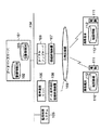
図1は本発明の第1の実施の形態に係る情報配信システムの一例を示す構成図である。
【0021】
この情報配信システムは、監視制御システム105や音声通報サーバ100等が接続されてなるLAN104から、公衆回線網109を介して各職員の有する携帯端末110や113に情報配信ができるように構成されている。
【0022】
LAN104はバス型LANであり、監視制御システム105、音声通報サーバ100の他、ダイアルアップサーバ106及びデータベースサーバ101が接続されて構成される。
【0023】
ここでまず、監視制御システム105は、配水系統、電力系統等における各設備・各機器の監視装置である。プラントで事故や異常等が発生すると、それを検知して事故や異常の発生した機器、場所、時刻、警報のレベル、警報内容等を一定のフォーマットに編集した異常通知を送信する。
【0024】
音声通報サーバ100は、データ音声両用回線終端装置108によって公衆回線網109に接続する。また、監視制御システム105が発信した警報情報を受信すると、適切な通報先を選択し、その番号の無線電話111(携帯電話やPHS等)に接続して警報内容を自動的に音声で通報する。
【0025】
データベースサーバ101は、警報情報データベース102と設備機器の位置情報データベース103を管理する。警報情報データベース102には、監視制御システム105が発生した全ての警報情報がデータベースサーバ101により受信され格納されている。また、設備機器の位置情報データベース103には、各設備や機器の位置情報が予め登録されている。
【0026】
ダイアルアップサーバ106は、回線終端装置107を介して公衆回線網109に接続する。
無線電話110が接続された携帯端末110や無線電話内蔵型携帯端末113は、例えばモバイル機能、及び表示手段や音声出力手段等の情報出力手段を備えたパーソナルコンピュータからなり、地図情報データベース112を備え、無線電話110を介して公衆回線網109と接続される。この携帯端末110,113は、設備機器の位置情報データベース103から当該設備や機器の位置情報を取得し、その表示画面の地図上に当該設備や機器の位置を表示するようになっている。
【0027】
この図1の構成をより具体化して現したのが図2である。
図2は本実施形態の情報配信システムの構成例を具体的に示した図であり、図1と同一部分には同一符号を付している。
【0028】
同図に示す監視制御システム105は、ある市における配水系統の監視制御を行うシステムである。
また、データ音声両用回線終端装置108は、DSVDモデム121及びターミナルアダプタ121から構成される。なお、DSVDモデム121は、データのみならず音声をも送信できるモデムである。
【0029】
回線終端装置107は、モデム123及びターミナルアダプタ124から構成される。さらに、無線電話111としては、PHS125が使用され、PHS基地局126を経由して公衆回線網109に接続される。
【0030】
次に、以上のように構成された本実施形態における情報配信システムの動作について説明する。
まず、監視制御システム105により市内の配水系統の流量や圧力等が監視されている。ここで、監視対象における事故や異常が検知されると、当該監視制御システム105から警報が出力され、LAN104を介して音声通報サーバ100及びデータベースサーバ101に伝送される。このとき、伝送されるのは、異常や事故の発生した機器、場所、時刻、警報(発生)のレベル、警報内容(現象)等の警報情報である。
【0031】
この警報情報は、データベースサーバ101における警報情報データベース102に項目毎に登録される。こうして、警報情報データベース102には全警報情報が蓄積されている。
【0032】
一方、LAN104上に送出された警報情報が一定の条件(例えば警報レベルが重警報)を満たしている場合には、音声通報サーバ100によって、当該警報情報から警報メッセージが音声情報として合成される。この警報メッセージは音声通報サーバ100からの制御によってDSVDサーバ121及びターミナルアダプタ122(データ音声両用回線終端装置108)から自動発信され、公衆回線網109,PHS基地局126を介して職員の持つPHS125(無線電話111)にて受信される。PHS125に着信した警報メッセージは、音声として職員に対して出力される。
【0033】
この警報メッセージを受けた職員は、携帯端末110又は無線電話内蔵型携帯端末113のPHS125によって、PHS基地局126,公衆回線網109,ターミナルアダプタ124,モデム123を介してダイアルアップサーバ106にダイアルアップ接続する。
【0034】
ダイアルアップ接続後、携帯端末110,113から警報情報データベース102に対して異常や故障の発生している設備や機器についての問い合わせが行われる。さらに、位置情報データベース103から当該機器や設備の位置情報が取得される。
【0035】
携帯端末110,113においては、その端末の表示画面に示された地図上に、取得された位置情報を基づいた当該設備や機器の場所が表示される。このとき表示される地図は、携帯端末110,113が保持している地図情報データベース112から作成される。
【0036】
こうして警報を受けた職員は、異常等が発生した設備の地図上の位置を確認できることとなる。
上述したように、本発明の実施の形態に係る情報配信システムは、警報情報が発生した場合には、適宜の携帯端末110,113にその旨が通知されるので、配水系統を構成する機器等に異常や故障が発生した場合に、音声通報機能等で市内巡回中の職員に自動的に通報ができる。
【0037】
また、現場への最短経路や当該設備での注意事項などの当該設備の場所や経路に関連した情報が端末に通知され、通報を受けた職員は、異常や故障が発生した機器の場所を端末の地図上で確認するなどできる。
【0038】
これにより、事故や異常への迅速な対応を可能とし、プラントや系統の被害を最小限に食い止め速やかに復旧させることができる。
(発明の第2の実施の形態)
本実施形態は、携帯端末110,113において、異常等発生の位置のみならず当該携帯端末110,113の位置を地図上に表示するものである。
【0039】
図3は本発明の第2の実施の形態に係る情報配信システムの一例を示す構成図であり、図1と同一部分には同一符号を付して説明を省略し、ここでは異なる部分についてのみ述べる。
【0040】
この情報配信システムは、携帯端末110及び113に、その端末位置情報を受信するためのGPS200を取り付ける。このGPS200は、GPSアンテナとその受信電波から位置算出する位置検出装置からなり、GPS衛星201からの信号を受信し、自己の位置を検出するようになっている。
【0041】
携帯端末110及び113は、位置情報データベース103からの位置情報受信時に、設備位置とともにGPS200にて取得した自端末位置を地図上に表示するようになっている。
【0042】
本実施形態の情報配信システムは、以上の点を除く他、第1の実施形態と同様に構成されている。
次に、このように構成された本実施形態における情報配信システムの動作について説明する。
【0043】
本実施形態における動作は、携帯端末110,113の位置情報の取得に関する部分以外は第1の実施形態と同様である。
まず、携帯端末110及び113においては、GPSアンテナにより衛星201からの電波が受信され、自己の位置が常に検出されている。
【0044】
また、携帯端末110及び113では、音声通報サーバ100から警報メッセージを受けると、ダイアルアップサーバ106への接続が行われ、さらにデータベースサーバ101から事故等発生設備の位置情報を受け取る。
【0045】
この事故等発生設備の位置情報の受信に伴い、端末110,113の地図上には、当該設備や機器の位置と同時にGPS200から得た端末の現在位置が表示される。
【0046】
上述したように、本発明の実施の形態に係る情報配信システムは、GPS200を設けたので、携帯端末110,113から当該端末位置を表示することができる。これにより、職員は現場に急行することが一層容易になる。
(発明の第3の実施の形態)
本実施形態は、第1の実施形態において、第2の実施形態とは異なる方法で携帯端末の位置情報を取得するものである。
【0047】
図4は本発明の第3の実施の形態に係る情報配信システムの一例を示す構成図であり、図1と同一部分には同一符号を付して説明を省略し、ここでは異なる部分についてのみ述べる。
【0048】
この情報配信システムは、LAN104にPHS位置情報取得装置300が接続され、さらに当該PHS位置情報取得装置300から回線終端装置301を介して公衆回線網109に接続されPHS事業所310に問い合わせができるようになっている他、第1の実施形態と同様に構成されている。なお、本実施形態では、携帯端末110及び113に用いられる無線電話は111はPHS125となっている。
【0049】
PHS位置情報取得装置300は、PHS事業所310に問い合わせることでPHS125が接続されているPHS基地局の位置情報を取得し、これを携帯端末110,113の位置情報として当該端末に送信する。
【0050】
この図4の構成をより具体化して現したのが図5である。
図5は本実施形態の情報配信システムの構成例を具体的に示した図であり、図2又は図4と同一部分には同一符号を付している。
【0051】
この情報配信システムにおいて、回線終端装置301は、それぞれモデム123及びターミナルアダプタ124と同様な構成を有するモデム302及びターミナルアダプタ303から構成される。
【0052】
次に、以上のように構成された本実施形態における情報配信システムの動作について説明する。
本実施形態における動作は、携帯端末110,113の位置情報の取得に関する部分以外は第1の実施形態と同様である。
【0053】
まず、警報メッセージ受信時に、携帯端末110,113からPHS位置情報取得装置300に対し、回線終端装置301(ターミナルアダプタ303及びモデム302)を介して自分のPHS301の接続している基地局の位置情報要求がなされる。
【0054】
この要求を受けたPHS位置情報取得装置300からPHS事業所310に対して位置情報要求のあった端末の接続基地局の位置が問い合わせられ、当該基地局の位置情報が取得される。
【0055】
PHSにおいては基地局と端末の位置に大きなずれはないから、この基地局位置が端末位置情報としてPHS位置情報取得装置300から要求のあった携帯端末110,113に返信される。
【0056】
この端末位置情報を受け取った携帯端末110や無線電話内蔵型携帯端末113においては、第1の実施形態と同様にして表示画面上に地図及び設備位置が表示されるとともに、当該端末位置情報に基づく現在位置が表示される。
【0057】
上述したように、本発明の実施の形態に係る情報配信システムは、PHS位置情報取得装置300を設け、PHS事業所310にPHS基地局の位置を問い合わせることができるので、携帯端末の位置を取得でき、当該携帯端末位置を画面上に表示させることができる。
(発明の第4の実施の形態)
本実施形態は、第2又は第3の実施形態において、携帯端末現在位置から事故等発生設備までの経路を算出し表示するようにしたものである。
【0058】
図6は本発明の第4の実施の形態に係る情報配信システムの一例を示す構成図であり、図5と同一部分には同一符号を付して説明を省略し、ここでは異なる部分についてのみ述べる。
【0059】
図6に示す情報配信システムは、携帯端末110及び113に設備までの経路を算出し表示する経路算出部320が設けられる他、第3の実施形態と同様に構成されている。なお、同経路算出部320以外は、図3に示す第2の実施形態と同様な構成を備えてGPSシステムで現在位置を取得するようにしてもよい。
【0060】
経路算出部320は、異常や故障の発生した機器や設備の位置情報と、PHS位置情報取得装置300若しくはGPS200の何れかから取得した端末位置情報に基づき、現在位置から機器や設備までの経路を算出し、画面の地図上に表示する。
【0061】
次に、以上のように構成された本実施形態における情報配信システムの動作について説明する。
本実施形態における動作は、経路算出表示に関する部分以外は第2又は第3の実施形態と同様である。
【0062】
携帯端末110,113においては、異常や故障の設備や機器および端末の位置情報及び自端末位置情報が取得されると、当該各位置情報及び地図情報に基づき、経路算出部320により、この2地点間の経路が探索され、最適な経路が地図上に表示される。
【0063】
経路探索は以下のように行う。
図7は経路探索の様子を示す図である。
地図情報112には、ノード(道路の分岐点)の座標とそのノードから移動可能なノードが地図情報の一部として記憶されており、図7にはノードとその座標、移動可能ノードの例が示されている。
【0064】
また、目標物の座標も登録しておく。図7ではαで示されている。職員の現在地Sから目標地点αへ行く経路は次のように求める。
現在地から目標値への経路を求める手順
ステップs1:Sの現在値の座標を得る。この例では(42.027,135.510)である。
【0065】
ステップs2:各ノードとSの直線距離を求め、最寄りノードを調べる。この例ではノードGである。
ステップs3:目標地点αの座標を得る。この例では(42.017,135.544)である。
【0066】
ステップs4:各ノードとαの直線距離を求め、最寄りノードを調べる。この例ではノードCである。
ステップs5:ノードCへ到達可能なノードを列挙し、それぞれのノードからノードCへの直線距離を計算する。この例ではノードB→C(距離=0.023),D→C(距離=0.017)である。なお、この例ではA−C間は一方通行であり、A→Cの移動はできない。
【0067】
ステップs6:ノードB,Dへ到達可能なノードを列挙し、それぞれのノードからノードCへの道のりを同様に計算する。ただし、直前のノードにはもどらない。また、到達可能なノードがない場合はその経路は捨てる。この例では以下の通りである。
【0068】
H→B→C(道のり=0.017 +0.023 =0.040 )
A→B→C(道のり=0.017 +0.023 =0.040 )
E→D→C(道のり=0.017 +0.017 =0.034 )
ステップs7:ノードH,A,Eへ到達可能なノードを列挙し、それぞれのノードからノードCへの道のりを同様に計算する。ただし、直前のノードには戻らない。また、到達可能なノードがない場合はその経路は捨てる。この例では以下の通りである。
【0069】
H→B→C…捨てる
G→A→B→C(道のり=0.017 +0.017 +0.023 =0.057 )
E→A→B→C(道のり=0.017 +0.017 +0.023 =0.057 )
A→E→D→C(道のり=0.017 +0.017 +0.017 =0.051 )
F→E→D→C(道のり=0.017 +0.017 +0.017 =0.051 )
以上より、Sの最寄りノードGまでの経路が見つかったので、S→G→A→B→C→αを経路として出力し表示する。なお、この経路の道のりは0.057である。
【0070】
上述したように、本発明の実施の形態に係る情報配信システムは、携帯端末110等に経路算出部320を設けたので、現在位置から現場までの最短経路を表示することができ、故障や異常の発生時に、現場へ急行して迅速に復旧作業を行うことができる。
(発明の第5の実施の形態)
本実施形態は、第3の実施形態において、複数職員のもつ各PHS125の位置を所得し、その位置情報から事故等発生設備に最も近い職員に警報メッセージを通報するようにしたものである。
【0071】
図8は本発明の第5の実施の形態に係る情報配信システムの一例を示す構成図であり、図4と同一部分には同一符号を付して説明を省略し、ここでは異なる部分についてのみ述べる。
【0072】
この情報配信システムは、音声通報サーバ100に通報先判定部330が設けられる他、第3の実施形態と同様に構成されている。
通報先判定部330は、音声通報サーバ100が監視制御システム105から警報情報を受けると、PHS位置情報取得装置300に職員の持つ全PHS125の位置情報取得を依頼する。さらにPHS位置情報取得装置300から取得した職員の持つ全PHS125の位置情報に基づいて、事故等が発生した設備に最も近いPHS125の携帯端末110,113を選択し警報メッセージの通報先として決定する。
【0073】
次に、以上のように構成された本実施形態における情報配信システムの動作について説明する。
本実施形態における動作は、通報先選択に関する部分以外は第3の実施形態と同様である。
【0074】
まず、音声通報サーバ100が監視制御システム105から警報情報を受けると、通報先判定部330によってPHS位置情報取得部300に対する各PHSの位置情報取得要求が出力される。
【0075】
この要求を受け取ったPHS位置情報取得部300によって、職員が保持し、かつ、その時点で電源が入っている全PHSの位置(PHS基地局の位置)がPHS事業所310に問い合わせされる。
【0076】
この位置情報はPHS位置情報取得部300から音声通報サーバ100に通知される。
通知された各PHS位置情報は、データベースサーバ101の位置情報データベース103から取得された事故等発生設備の位置情報と比較され、つまり各PHS125から機器や設備までの距離が計算されて、当該設備位置に最も近いPHS125が選択される。
【0077】
以下、この選択されたPHS125を所有する職員に対して上記実施形態と同様にして音声通報サーバ100から警報メッセージが出力され、以降の各処理が実行される。
【0078】
なお、PHSと当該設備との距離は、例えば第4の実施形態に示した経路算出部320の処理と同様な手順により求められる。また例えば単純に両者の直線距離を当該距離としてもよい。
【0079】
上述したように、本発明の実施の形態に係る情報配信システムは、各職員の現在位置を把握しその上で通報先を判定するようにしたので、最も現場近くにいる職員に連絡することができる。
【0080】
また、職員の現在位置に関連した情報を配信したりすることも可能である。
なお、本実施形態では、各PHSの位置情報を第3の実施形態で説明した方法で取得するようにしたが、この位置情報は第2の実施形態で説明した方法を用いて取得するようにしてもよい。この点は、以下の第6,第7の実施形態等においても同様である。
(発明の第6の実施の形態)
本実施形態は、設備までの距離に加えて、各職員の専門性等をも考慮して通報先を判定するようにしたものである。
【0081】
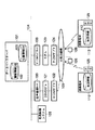
図9は本発明の第6の実施の形態に係る情報配信システムの一例を示す構成図であり、図8と同一部分には同一符号を付して説明を省略し、ここでは異なる部分についてのみ述べる。
【0082】
この情報配信システムは、データベースサーバ101に職員データベース400が設けられ、通報先判定部330′に当該データベース400を考慮した判定処理機能が付加される他、第3の実施形態と同様に構成されている。
【0083】
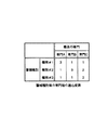
職員データベース400は、全職員の専門分野についての情報、及び各警報の種別に対応した専門分野の適応度を示す適応度表を格納している。
図10は職員データベースに格納される適応度表の内容例を示す図である。
【0084】
例えば専門分野がAの職員は、種別#1の警報内容に対して適応度fが3であり、種別#2、#3に対しては適応度fが1であることを示している。
通報先判定部330′は、第5の実施形態の通報先判定部330と同様な処理を行う他、PHS選択としては単に事故等発生設備に最も近いものとはせずに、次のような基準に基づいて行う。すなわち各PHSと設備との距離をd、適応度をfとして、担当職員の専門と設備までの距離とを考慮した指数i=d/fを求める。この指数iを各PHS125について求め、指数iが最小のPHS125を通報先として決定する。
【0085】
次に、以上のように構成された本実施形態における情報配信システムの動作について説明する。
本実施形態における動作は、通報先PHSの選択に関する部分以外は第5の実施形態と同様である。
【0086】
まず、監視制御システム105より警報を受けた音声通報サーバ100の通報先判定部330′においては、位置情報に関するデータ取得のみならず、データベースサーバ101の職員データベース400から各職員の専門情報が取得されるとともに、警報種別に対応した各専門分野の適応度情報が取得される。
【0087】
この専門情報及び適応度情報に基づき、通報先判定部330′によって各職員の適応度fが計算される。さらに、各PHSと設備との距離dと適応度fとから各PHS125についての指数i=d/fが算出され、指数iが最小となるPHS125が通報先として決定される。
【0088】
以下、この選択されたPHS125を所有する職員に対して上記実施形態と同様にして音声通報サーバ100から警報メッセージが出力され、以降の各処理が実行される。
【0089】
上述したように、本発明の実施の形態に係る情報配信システムは、各職員の現在位置のみならずその専門性をも考慮して通報先を選択するようにしたので、より適切な職員に通報することができ、的確かつ迅速な設備復旧を実現させることができる。
(発明の第7の実施の形態)
第5又は第6の実施形態では、警報メッセージを一の携帯端末110,113に通知するようにしたが、本実施形態は、一定の基準を満たす複数の携帯端末110,113に警報メッセージを通知するようにしたものである。
【0090】
本実施形態の情報配信システムは、図8又は図9に示す通報先判定部330又は330′において、複数の通報先が選択されるようになっており、音声通報サーバ100等の各部が複数通報に対応するようになっている他、第5又は第6の実施形態と同様に構成されている。
【0091】
通報先判定部330又は330′は、設備までの距離が短い順に所定数のPHS125を選択し、また、指数iが小さい順に所定数のPHS125を選択するようになっている。
【0092】
次に、以上のように構成された本実施形態における情報配信システムの動作について説明する。
本実施形態における動作は、通報先PHSの選択数に関する部分以外は第5又は第6の実施形態と同様である。
【0093】
すなわち通報先判定部330又は330′により、第5又は第6の実施形態と同様な基準で、但し唯一でなく複数のPHS125が選択される。選択数は適宜設定できるようになっており(n番目まで)、選択は上記のごとく距離又は指数iの小さいものから順に行われる。なお、選択は所定数でなく、所定の基準(距離又は指数i)を満たすもの全てとしてもよい。
【0094】
以下、この選択されたPHS125を所有する職員に対して上記実施形態と同様にして音声通報サーバ100から警報メッセージが出力され、以降の各処理が実行される。
【0095】
上述したように、本発明の実施の形態に係る情報配信システムは、複数の職員に警報メッセージを送信するようにしたので、確実な設備復旧を実現させることができる。
(発明の第8の実施の形態)
本実施形態は、第1の実施形態に機器等の位置情報提供のみならず、各種のガイド機能を付加したものである。
【0096】
図11は本発明の第8の実施の形態に係る情報配信システムの一例を示す構成図であり、図1と同一部分には同一符号を付して説明を省略し、ここでは異なる部分についてのみ述べる。
【0097】
本実施形態の情報配信システムは、データベースサーバ101内にガイダンスデータベース500が設けられ、ダイアルアップサーバ106にガイド処理部501が設けられる他、第1の実施形態と同様に構成されている。
【0098】
ガイダンスデータベース500には、各設備や機器に関するガイダンス、仕様、操作方法等のガイド情報が格納されている。
ガイド処理部501は、携帯端末110や無線電話内蔵型携帯端末113からの要求を受けると、対応する設備や機器についてのガイド情報を要求元に送信する。
【0099】
次に、以上のように構成された本実施形態における情報配信システムの動作について説明する。
本実施形態における動作は、設備ガイドに関する部分以外は第1の実施形態と同様である。
【0100】
まず、携帯端末110や無線電話内蔵型携帯端末113において設備等の位置情報が取得されると、現在異常や故障の発生している当該設備等についてのガイド情報が当該携帯端末110等からダイアルアップサーバ106に要求される。
【0101】
要求を受けたダイアルアップサーバ106のガイド処理部501によって、ガイダンスデータベース500から当該設備や機器に関するガイダンス、仕様、操作方法などが取得され、当該携帯端末110等に送信される。
【0102】
携帯端末110等に送信されたガイド情報は、端末画面上に表示され、または音声で出力される。
上述したように、本発明の実施の形態に係る情報配信システムは、ガイダンスデータベース500を設け、ガイド情報を携帯端末から表示させるようにしたので、現場では異常を起こした機器や設備のガイダンスを端末上で見ることができる。
【0103】
なお、本実施形態では、ガイド処理部501をダイアルアップサーバ106に設けるようにしたが、当該ガイド処理部501は例えば音声通報サーバ100に設けるようにしてもよい。
(発明の第9の実施の形態)
本実施形態は、第2又は第3の実施形態において、保守や点検の対象となる設備や機器の点検項目を携帯端末110等から表示するシステムである。
【0104】
図12は本発明の第9の実施の形態に係る情報配信システムの一例を示す構成図であり、図3と同一部分には同一符号を付して説明を省略し、ここでは異なる部分についてのみ述べる。
【0105】
本実施形態の情報配信システムは、データベースサーバ101内に点検項目データベース600が設けられ、当該データベース500内のデータを公衆回線網109を介して携帯端末110,113から表示できるように構成される他、第2又は第3の実施形態と同様に構成されている。なお、図12には第2の実施形態に対応する構成が示されている。
【0106】
点検項目データベース600は、各設備や機器の点検項目についての情報を格納する。
次に、以上のように構成された本実施形態における情報配信システムの動作について説明する。
【0107】
本実施形態における動作は、点検項目情報の取得及び表示に関する部分以外は第2又は第3の実施形態と同様である。
まず保守や点検時に、携帯端末110又は無線電話内蔵型携帯端末113からデータベースサーバ101に対し、端末現在位置の情報が伝えられるとともに、その現在位置の設備や機器の点検項目情報の問い合わせが行われる。
【0108】
データベースサーバ101では、位置情報データベース103が検索されることで端末現在位置に存在する設備機器が特定され、さらに、点検項目データベース600が検索される。
【0109】
この点検項目データベース600の検索により、端末現在位置にある設備、機器の点検項目が所得され、その取得情報が携帯端末110等に送信される。携帯端末110等においては受信した点検項目が画面上に表示され、あるいは音声出力される。
【0110】
上述したように、本発明の実施の形態に係る情報配信システムは、点検項目データベース600を設け、点検項目を取得できるようにしたので、的確な保守点検を行うことができる。
【0111】
なお、本実施形態の情報配信システムでは、設備等の異常警報を受けたときのみならず、通常時の保守等における点検項目情報取得にも利用できる。
つまり、このような端末を携帯することにより、点検員は点検すべき機器の前に立ち、端末に点検項目の受信を指示する(メニューを選択する、ボタンを押す等)だけで、これから点検する機器の点検項目を端末上に表示することができる。
【0112】
したがって、日常の保守点検業務を効率化省力化することもできる。
(発明の第10の実施の形態)
本実施形態は、第9の実施形態において、保守や点検の結果をデータベースサーバ101へ保存するシステムである。
【0113】
図13は本発明の第10の実施の形態に係る情報配信システムの一例を示す構成図であり、図12と同一部分には同一符号を付して説明を省略し、ここでは異なる部分についてのみ述べる。
【0114】
本実施形態の情報配信システムは、データベースサーバ101内に点検結果データベース700が設けられ、保守や点検の結果が携帯端末110、公衆回線網109等を介して当該データベース700に保存できるように構成される他、第9の実施形態と同様に構成されている。なお、図13には第2の実施形態に対応する構成が示されている。
【0115】
点検結果データベース700は、携帯端末110や無線電話内蔵型携帯端末113から入力された設備や機器の点検結果が登録されるようになっている。当該データベース700は、予め作成された点検結果登録用のテーブル等からなっている。
【0116】
次に、以上のように構成された本実施形態における情報配信システムの動作について説明する。
本実施形態における動作は、点検結果をデータベース700に保存する部分以外は第9の実施形態と同様である。
【0117】
すなわちまず第9の実施形態と同様に、携帯端末110や無線電話内蔵型携帯端末113において、その現在位置にある機器や設備の点検項目情報が取得される。職員はその項目を点検し、点検結果を携帯端末110等に入力する。
【0118】
携帯端末110等から入力された点検結果が公衆回線網109を介してデータベースサーバ101に送信され、点検結果データベース700に登録される。
上述したように、本発明の実施の形態に係る情報配信システムは、現在位置の位置情報から機器や設備の点検項目を取得し、点検結果を端末から入力することで保守結果を点検結果データベース700に保存できるようにしたので、保守点検作業の効率化省力化を図ることができる。
【0119】
なお、本実施形態の情報配信システムは、第9の実施形態と同様に、通常時の保守等における点検項目情報取得保存にも利用できる。
したがって、日常の保守点検業務においては、点検項目や機器の操作方法などを職員の携帯する端末に配信したり、保守点検結果を端末からサーバに登録することが可能である。
【0120】
このような端末を携帯することにより、点検員は点検すべき機器の前に立ち、点検項目の受信を指示する(メニューを選択する、ボタンを押す等)だけで、これから点検する機器の点検項目を端末上に表示することができる。受信した点検項目の情報には、機器を特定する情報(A設備1号ポンプ等)を付加しておくことにより、当該機器の前を離れてもそれがどの機器の点検項目であるかがわかる。同様に点検結果もどの機器の点検結果であるかがわかる。
【0121】
なお、本発明は、上記各実施の形態に限定されるものでなく、その要旨を逸脱しない範囲で種々に変形することが可能である。
また、実施形態に記載した手法は、計算機(コンピュータ)に実行させることができるプログラム(ソフトウエア手段)として、例えば磁気ディスク(フロッピーディスク、ハードディスク等)、光ディスク(CD−ROM、DVD等)、半導体メモリ等の記憶媒体に格納し、また通信媒体により伝送して頒布することもできる。なお、媒体側に格納されるプログラムには、計算機に実行させるソフトウエア手段(実行プログラムのみならずテーブルやデータ構造も含む)を計算機内に構成させる設定プログラムをも含むものである。本装置を実現する計算機は、記憶媒体に記録されたプログラムを読み込み、また場合により設定プログラムによりソフトウエア手段を構築し、このソフトウエア手段によって動作が制御されることにより上述した処理を実行する。
【0122】
【発明の効果】
以上詳記したように本発明によれば、職員に警報内容のみならず設備への経路情報等の情報を通知して事故や異常への迅速な対応を可能とし、ひいては、プラントや系統の被害を最小限に食い止め速やかに復旧させることができる情報配信システムを提供することができる。
【0123】
また、本発明によれば、事故や異常への迅速な対応ができる最適な職員に連絡することを可能とし、ひいては、プラントや系統の被害を最小限に食い止め速やかに復旧させることができる情報配信システムを提供することができる。
【図面の簡単な説明】
【図1】本発明の第1の実施の形態に係る情報配信システムの一例を示す構成図。
【図2】同実施形態の情報配信システムの構成例を具体的に示した図。
【図3】本発明の第2の実施の形態に係る情報配信システムの一例を示す構成図。
【図4】本発明の第3の実施の形態に係る情報配信システムの一例を示す構成図。
【図5】同実施形態の情報配信システムの構成例を具体的に示した図。
【図6】本発明の第4の実施の形態に係る情報配信システムの一例を示す構成図。
【図7】経路探索の様子を示す図。
【図8】本発明の第5の実施の形態に係る情報配信システムの一例を示す構成図。
【図9】本発明の第6の実施の形態に係る情報配信システムの一例を示す構成図。
【図10】職員データベースに格納される適応度表の内容例を示す図。
【図11】本発明の第8の実施の形態に係る情報配信システムの一例を示す構成図。
【図12】本発明の第9の実施の形態に係る情報配信システムの一例を示す構成図。
【図13】本発明の第10の実施の形態に係る情報配信システムの一例を示す構成図。
【符号の説明】
100…音声通報サーバ
101…データベースサーバ
102…警報情報データベース
103…設備機器の位置情報データベース
104…LAN
105…監視制御システム
106…ダイアルアップサーバ
107…回線終端装置
108…データ、音声両用回線終端装置
109…公衆回線網
110…携帯端末
111…携帯電話、PHS等の無線電話
112…地図情報データベース
113…無線電話内蔵型携帯端末
121…DSVDモデム
122,124…ターミナルアダプタ
123…モデム
125…PHS
126…PHS基地局
200…GPS
201…GPS衛星
300…PHS位置情報取得装置
301…PHS
302…モデム
303…ターミナルアダプタ
310…PHS事業所
320…経路算出部
330,330′…通報先判定部
400…職員データベース
500…ガイダンスデータベース
501…ガイド処理部
600…点検項目データベース
700…点検結果データベース[0001]
BACKGROUND OF THE INVENTION
This invention distributes alarm information when accidents or abnormalities are output from monitoring and control systems such as water distribution systems, power systems, etc., and distributes inspection lists and operation methods for equipment during normal maintenance inspections. The present invention relates to an information distribution system suitable for doing so.
[0002]
[Prior art]
Generally, when an accident or abnormality occurs in a water distribution system, an electric power system, etc., the monitoring control device issues an alarm. In such a case, the alarm is communicated to the waiting staff by radio or telephone.
[0003]
Here, when the alarm notification is automatically performed, the previously recorded voice is reproduced and notified, or the alarm message from the voice synthesizer is automatically transmitted. Therefore, the information to be communicated is only the situation of an accident or abnormality, and it is difficult to make a report based on judgments that take various situations into consideration.
Also, maintenance inspections in normal times are dealt with by the inspector memorizing the inspection item list, the operation method of the equipment, etc. or bringing the list.
[0004]
[Problems to be solved by the invention]
Here, since the water distribution system, the power system, and the like are facilities closely related to the public life, there is a particularly strong demand to return immediately when an abnormality occurs. Therefore, in the event of an accident or abnormality, it is important to reliably deliver an alarm issued by the monitoring control device from the notification device to the staff of the notification target and respond quickly.
[0005]
However, with the conventional technology, it was not possible to transmit information that could improve the quick response to the shortest route to the site and precautions at the facility, only by transmitting information on the accident or abnormality that is the content of the alarm. .
[0006]
In addition, the water distribution system and the power system are systems in which facilities are scattered in a very wide area such as a city or a prefecture, and it is necessary to make a report in consideration of this characteristic.
However, since the conventional technology does not consider the current location of the staff reporting the alarm, it was not possible to contact the staff near the facility where the abnormality occurred in a timely manner.
[0007]
Furthermore, in daily maintenance and inspection work, inspection items, device operation methods, and the like cannot be distributed to a terminal carried by the staff, and maintenance inspection results cannot be registered in the server from the terminal. Therefore, when inspecting an unattended remote facility, it is necessary to conduct another inspection if the on-site staff does not have the necessary information. Also, the maintenance inspection results could not be checked immediately in the central monitoring room.
[0008]
The present invention has been made in consideration of such a situation, and its first purpose is to notify not only the alarm contents but also information such as the route information to the facility to the staff so that an accident or abnormality can be promptly performed. An object is to provide an information distribution system that can cope with the damage and, in turn, minimize damage to the plant and system and restore it quickly.
[0009]
The second purpose is to establish an information distribution system that can contact the most appropriate staff capable of promptly responding to accidents and abnormalities, and thus prevent damage to plants and systems to a minimum and restore them quickly. It is to provide.
[0010]
[Means for Solving the Problems]
In order to solve the above-mentioned problems, the invention corresponding to
[0011]
Here, first, when alarm information about one of the facilities is generated, a notification means provided in the monitoring control device notifies that to the portable terminal.
Next, upon receiving an equipment location information acquisition request from the mobile terminal that has received the alarm occurrence, the location information database storing the location information of a plurality of facilities is searched, and the location information of the equipment related to the alarm information Is sent to the mobile terminal.
[0012]
In the portable terminal, when the position information of the facility related to the alarm information is received from the monitoring control device, the position information is output by the information output means.
Therefore, it is possible to promptly respond to accidents and abnormalities by notifying the staff of not only the alarm contents but also information such as route information to the equipment, so that damage to the plant and system can be minimized and promptly restored. Can do.
[0013]
Next, the claim1The invention corresponding toThe groundA map database for storing figure information is provided in the portable terminal.
Based on the map information in the map database and the facility position information related to the alarm information, the facility position is displayed and output on the map by the information output means.
[0014]
Next, the claim1The invention corresponding to, SupervisorThe terminal position acquisition means provided in the vision control device makes an inquiry to a mobile communication establishment, and acquires the position of the base station to which the mobile communication means is connected. Since the effective area of the base station is a limited narrow range, the base station position is notified to the mobile terminal as the mobile terminal position.
[0015]
In the portable terminal, the current position of the terminal acquired from the monitoring control device is displayed on the map by the information output means.
In the invention corresponding to
Accordingly, the shortest path from the current position to the site can be displayed, and when a failure or abnormality occurs, the site can be promptly restored and the restoration work can be performed quickly.
Furthermore, in the invention corresponding to
In addition, the alarm information described above is an abnormality notification in which the device, location, time, alarm (occurrence) level, alarm content (phenomenon) in which an abnormality or accident has occurred is edited in a certain format, and this alarm information is constant. When the condition is satisfied, an alarm message is synthesized as voice information from the alarm information by the reporting means, and the alarm message is reported to the portable terminal by control from the reporting means.
Upon receiving the alarm information, the reporting means requests the terminal position acquisition means to acquire the position information of all the mobile terminals held by the staff, and based on the obtained position information of all the mobile terminals, the distance between each mobile terminal and the equipment D,Stored in staff databaseAn index i = d / f is calculated for each mobile terminal, taking into account the specialization of the staff in charge and the distance to the equipment, with the fitness level in the fitness table as f, and the mobile terminal with the smallest index i is determined as the report destination It has a function to do.
Therefore, since the notification destination is selected in consideration of not only the current position of each staff member but also their expertise, it is possible to report to more appropriate staff members and to realize accurate and prompt facility restoration. it can.
Next, the invention corresponding to
[0017]
Next, the claim3The invention corresponding to the first aspect is as follows.Or claim 2In the corresponding invention, an inspection item database for registering inspection items for each facility is provided in the monitoring control device.
[0018]
Further, in the monitoring control device, the equipment in the vicinity of the current position of the mobile terminal obtained from the terminal position acquisition means is searched from the position information database, and the inspection items of the searched equipment are searched from the inspection item database and the mobile Sent to the terminal.
[0019]
Therefore, it is possible to contact the most suitable staff who can promptly respond to accidents and abnormalities, and as a result, damage to the plant and system can be minimized and promptly restored.
[0020]
DETAILED DESCRIPTION OF THE INVENTION
Embodiments of the present invention will be described below.
(First Embodiment of the Invention)
FIG. 1 is a block diagram showing an example of an information distribution system according to the first embodiment of the present invention.
[0021]
This information distribution system is configured so that information can be distributed from the
[0022]
The
[0023]
First, the
[0024]
The
[0025]
The
[0026]
The dial-up
The
[0027]
FIG. 2 shows the configuration of FIG. 1 more concretely.
FIG. 2 is a diagram specifically illustrating a configuration example of the information distribution system according to the present embodiment. The same reference numerals are given to the same portions as those in FIG.
[0028]
A
The data / voice mixed
[0029]
The
[0030]
Next, the operation of the information distribution system in the present embodiment configured as described above will be described.
First, the
[0031]
This alarm information is registered for each item in the
[0032]
On the other hand, when the alarm information transmitted on the
[0033]
The staff who has received this warning message dials up to the dial-up
[0034]
After dial-up connection, the
[0035]
In the
[0036]
The staff who received the warning in this way can confirm the position on the map of the facility where the abnormality or the like has occurred.
As described above, in the information distribution system according to the embodiment of the present invention, when alarm information is generated, the appropriate
[0037]
In addition, information related to the location and route of the equipment, such as the shortest route to the site and precautions for the equipment, is notified to the terminal. You can check on the map.
[0038]
As a result, it is possible to promptly respond to accidents and abnormalities, minimize damage to the plant and system, and quickly restore the damage.
(Second Embodiment of the Invention)
In the present embodiment, the positions of the
[0039]
FIG. 3 is a block diagram showing an example of an information distribution system according to the second embodiment of the present invention. The same parts as those in FIG. State.
[0040]
In this information distribution system,
[0041]
The
[0042]
The information distribution system of this embodiment is configured in the same manner as in the first embodiment except for the above points.
Next, the operation of the information distribution system in the present embodiment configured as described above will be described.
[0043]
The operation in this embodiment is the same as that in the first embodiment except for the portion relating to the acquisition of the position information of the
First, in the
[0044]
In addition, when receiving an alarm message from the
[0045]
Accompanying the reception of the location information of the facility where the accident occurred, the current location of the terminal obtained from the
[0046]
As described above, since the information distribution system according to the embodiment of the present invention is provided with the
(Third embodiment of the invention)
In the first embodiment, the position information of the mobile terminal is acquired in the first embodiment by a method different from that in the second embodiment.
[0047]
FIG. 4 is a block diagram showing an example of an information distribution system according to the third embodiment of the present invention. The same parts as those in FIG. State.
[0048]
In this information distribution system, a PHS location
[0049]
The PHS location
[0050]
FIG. 5 shows the configuration of FIG. 4 more concretely.
FIG. 5 is a diagram specifically showing a configuration example of the information distribution system of the present embodiment, and the same reference numerals are given to the same parts as those in FIG. 2 or FIG.
[0051]
In this information distribution system, the line termination device 301 includes a
[0052]
Next, the operation of the information distribution system in the present embodiment configured as described above will be described.
The operation in this embodiment is the same as that in the first embodiment except for the portion relating to the acquisition of the position information of the
[0053]
First, when receiving an alarm message, the location information of the base station to which the PHS 301 is connected to the PHS location
[0054]
The PHS location
[0055]
In the PHS, since there is no large difference between the positions of the base station and the terminal, the base station position is returned as the terminal position information to the
[0056]
In the
[0057]
As described above, the information distribution system according to the embodiment of the present invention includes the PHS location
(Fourth embodiment of the invention)
In this embodiment, in the second or third embodiment, a route from the current position of the mobile terminal to an accident occurrence facility is calculated and displayed.
[0058]
FIG. 6 is a block diagram showing an example of an information distribution system according to the fourth embodiment of the present invention. The same parts as those in FIG. State.
[0059]
The information distribution system shown in FIG. 6 is configured in the same manner as in the third embodiment, except that the
[0060]
The
[0061]
Next, the operation of the information distribution system in the present embodiment configured as described above will be described.
The operation in this embodiment is the same as that in the second or third embodiment except for the portion related to the route calculation display.
[0062]
In the
[0063]
The route search is performed as follows.
FIG. 7 is a diagram showing a state of route search.
The
[0064]
Also, the coordinates of the target are registered. In FIG. 7, it is indicated by α. The route from the current location S of the staff to the target point α is obtained as follows.
Procedure for obtaining the route from the current location to the target value
Step s1: Obtain the coordinates of the current value of S. In this example, (42.027, 135.510).
[0065]
Step s2: The straight line distance between each node and S is obtained, and the nearest node is examined. In this example, it is node G.
Step s3: Obtain the coordinates of the target point α. In this example, (42.015, 135.544).
[0066]
Step s4: The distance between each node and α is obtained, and the nearest node is examined. In this example, it is node C.
Step s5: The nodes that can reach the node C are listed, and the straight line distance from each node to the node C is calculated. In this example, node B → C (distance = 0.023) and D → C (distance = 0.177). In this example, A-C is one-way, and A → C cannot be moved.
[0067]
Step s6: List nodes that can reach nodes B and D, and calculate the path from each node to node C in the same manner. However, it does not return to the previous node. If there is no reachable node, the route is discarded. In this example:
[0068]
H-> B-> C (Distance = 0.017 + 0.023 = 0.040)
A-> B-> C (Distance = 0.017 + 0.023 = 0.040)
E-> D-> C (Distance = 0.017 + 0.017 = 0.034)
Step s7: Nodes that can reach the nodes H, A, and E are listed, and the path from each node to the node C is calculated in the same manner. However, it does not return to the previous node. If there is no reachable node, the route is discarded. In this example:
[0069]
H → B → C ... Throw away
G-> A-> B-> C (Distance = 0.017 +0.017 +0.023 = 0.057)
E-> A-> B-> C (Distance = 0.017 +0.017 +0.023 = 0.057)
A-> E-> D-> C (Distance = 0.017 + 0.017 + 0.017 = 0.051)
F-> E-> D-> C (Distance = 0.017 +0.017 +0.017 = 0.051)
As described above, since the route to the nearest node G of S is found, S → G → A → B → C → α is output and displayed as a route. The path of this route is 0.057.
[0070]
As described above, since the information distribution system according to the embodiment of the present invention includes the
(Fifth embodiment of the invention)
In the third embodiment, the position of each
[0071]
FIG. 8 is a block diagram showing an example of an information distribution system according to the fifth embodiment of the present invention. The same parts as those in FIG. State.
[0072]
This information distribution system is configured in the same manner as in the third embodiment except that the
When the
[0073]
Next, the operation of the information distribution system in the present embodiment configured as described above will be described.
The operation in this embodiment is the same as that in the third embodiment except for the part related to the report destination selection.
[0074]
First, when the
[0075]
The PHS location
[0076]
This position information is notified from the PHS position
The notified PHS position information is compared with the position information of the facility such as an accident acquired from the
[0077]
Thereafter, an alarm message is output from the
[0078]
Note that the distance between the PHS and the equipment is obtained, for example, by the same procedure as the processing of the
[0079]
As described above, the information distribution system according to the embodiment of the present invention grasps the current position of each staff member and determines the report destination on that, so that the staff member closest to the site can be contacted. it can.
[0080]
It is also possible to distribute information related to the current position of the staff.
In this embodiment, the position information of each PHS is acquired by the method described in the third embodiment. However, this position information is acquired by using the method described in the second embodiment. May be. This also applies to the following sixth and seventh embodiments.
(Sixth embodiment of the invention)
In this embodiment, in addition to the distance to the equipment, the report destination is determined in consideration of the expertise of each staff member.
[0081]
FIG. 9 is a block diagram showing an example of an information distribution system according to the sixth embodiment of the present invention. The same parts as those in FIG. State.
[0082]
This information distribution system is configured in the same manner as in the third embodiment except that a
[0083]
The
FIG. 10 is a diagram showing an example of the contents of the fitness table stored in the staff database.
[0084]
For example, a staff member with a specialized field A indicates that the fitness level f is 3 for the
The report destination determination unit 330 ′ performs the same process as the report destination determination unit 330 of the fifth embodiment, and as a PHS selection, it is not simply the closest to the occurrence facility such as an accident. Based on criteria. That is, an index i = d / f is calculated in consideration of the specialty of the staff in charge and the distance to the equipment, where d is the distance between each PHS and the equipment and f is the fitness. This index i is obtained for each
[0085]
Next, the operation of the information distribution system in the present embodiment configured as described above will be described.
The operation in the present embodiment is the same as that in the fifth embodiment except for the part related to selection of the report destination PHS.
[0086]
First, in the notification destination determination unit 330 ′ of the
[0087]
Based on the specialized information and the fitness information, the report destination determination unit 330 ′ calculates the fitness f of each staff member. Further, an index i = d / f for each
[0088]
Thereafter, an alarm message is output from the
[0089]
As described above, the information distribution system according to the embodiment of the present invention selects the report destination in consideration of not only the current position of each staff member but also their expertise, so that the more appropriate staff member is notified. It is possible to achieve accurate and quick equipment restoration.
(Seventh embodiment of the invention)
In the fifth or sixth embodiment, an alarm message is notified to one
[0090]
In the information distribution system of this embodiment, a plurality of report destinations are selected in the report destination determination unit 330 or 330 ′ shown in FIG. 8 or FIG. 9, and each unit such as the
[0091]
The report destination determination unit 330 or 330 ′ selects a predetermined number of
[0092]
Next, the operation of the information distribution system in the present embodiment configured as described above will be described.
The operation in the present embodiment is the same as that in the fifth or sixth embodiment except for the portion related to the number of selected report destination PHSs.
[0093]
That is, the report destination determination unit 330 or 330 ′ selects a plurality of
[0094]
Thereafter, an alarm message is output from the
[0095]
As described above, the information distribution system according to the embodiment of the present invention transmits an alarm message to a plurality of staff members, so that reliable facility restoration can be realized.
(Eighth Embodiment of the Invention)
This embodiment is obtained by adding various guide functions to the first embodiment in addition to providing position information of devices and the like.
[0096]
FIG. 11 is a block diagram showing an example of an information distribution system according to the eighth embodiment of the present invention. The same parts as those in FIG. State.
[0097]
The information distribution system of this embodiment is configured in the same manner as in the first embodiment except that a
[0098]
The
When the
[0099]
Next, the operation of the information distribution system in the present embodiment configured as described above will be described.
The operation in this embodiment is the same as that in the first embodiment except for the part related to the equipment guide.
[0100]
First, when location information such as equipment is acquired in the
[0101]
The
[0102]
The guide information transmitted to the
As described above, the information distribution system according to the embodiment of the present invention provides the
[0103]
In this embodiment, the
(Ninth embodiment of the invention)
This embodiment is a system that displays the inspection items of equipment and equipment that are the targets of maintenance and inspection from the
[0104]
FIG. 12 is a block diagram showing an example of an information distribution system according to the ninth embodiment of the present invention. The same parts as those in FIG. State.
[0105]
The information distribution system of the present embodiment is configured such that an
[0106]
The
Next, the operation of the information distribution system in the present embodiment configured as described above will be described.
[0107]
The operation in this embodiment is the same as that in the second or third embodiment except for the portion relating to the acquisition and display of inspection item information.
First, at the time of maintenance or inspection, information on the current position of the terminal is transmitted from the
[0108]
In the
[0109]
By searching the
[0110]
As described above, since the information distribution system according to the embodiment of the present invention is provided with the
[0111]
Note that the information distribution system of the present embodiment can be used not only when receiving an abnormality alarm for equipment or the like, but also for acquiring inspection item information during normal maintenance or the like.
In other words, by carrying such a terminal, the inspector stands in front of the equipment to be inspected and instructs the terminal to receive inspection items (select a menu, press a button, etc.), and inspect from now on. Equipment inspection items can be displayed on the terminal.
[0112]
Therefore, daily maintenance inspection work can be made more efficient and labor-saving.
(Tenth embodiment of the invention)
The present embodiment is a system for storing the results of maintenance and inspection in the
[0113]
FIG. 13 is a block diagram showing an example of an information distribution system according to the tenth embodiment of the present invention. The same parts as those in FIG. State.
[0114]
The information distribution system of the present embodiment is configured such that an
[0115]
The
[0116]
Next, the operation of the information distribution system in the present embodiment configured as described above will be described.
The operation in the present embodiment is the same as that in the ninth embodiment except for the part that stores the inspection result in the
[0117]
That is, first, as in the ninth embodiment, in the
[0118]
The inspection result input from the
As described above, the information distribution system according to the embodiment of the present invention acquires the inspection items of equipment and facilities from the position information of the current position, and inputs the inspection results from the terminal, thereby obtaining the maintenance results as the
[0119]
Note that the information distribution system of this embodiment can also be used for acquiring and storing inspection item information in normal maintenance and the like, as in the ninth embodiment.
Therefore, in daily maintenance and inspection work, it is possible to distribute inspection items and device operation methods to a terminal carried by a staff member, and register maintenance inspection results from the terminal to a server.
[0120]
By carrying such a terminal, the inspector stands in front of the equipment to be inspected, and instructs to receive the inspection items (select menu, press a button, etc.). Can be displayed on the terminal. By adding information (A facility No. 1 pump, etc.) that identifies the device to the received inspection item information, it is possible to know which device is the inspection item even if it leaves the front of the device. . Similarly, it can be seen which device is the inspection result.
[0121]
The present invention is not limited to the above embodiments, and various modifications can be made without departing from the scope of the invention.
The method described in the embodiment is a program (software means) that can be executed by a computer (computer), for example, a magnetic disk (floppy disk, hard disk, etc.), an optical disk (CD-ROM, DVD, etc.), a semiconductor, etc. It can be stored in a storage medium such as a memory, or transmitted and distributed via a communication medium. The program stored on the medium side includes a setting program for configuring software means (including not only the execution program but also a table and data structure) to be executed in the computer. A computer that implements the present apparatus reads the program recorded in the storage medium, constructs software means by a setting program in some cases, and executes the processing described above by controlling the operation by the software means.
[0122]
【The invention's effect】
As described above in detail, according to the present invention, not only the alarm contents but also information such as route information to the facility can be notified to enable quick response to accidents and abnormalities. It is possible to provide an information distribution system that can prevent and minimize recovery of information quickly.
[0123]
In addition, according to the present invention, it is possible to contact an optimal staff capable of promptly responding to an accident or abnormality, and in turn, information distribution that can prevent damage to the plant or system to a minimum and restore it quickly. A system can be provided.
[Brief description of the drawings]
FIG. 1 is a configuration diagram showing an example of an information distribution system according to a first embodiment of the present invention.
FIG. 2 is a diagram specifically illustrating a configuration example of an information distribution system according to the embodiment.
FIG. 3 is a configuration diagram showing an example of an information distribution system according to a second embodiment of the present invention.
FIG. 4 is a configuration diagram showing an example of an information distribution system according to a third embodiment of the present invention.
FIG. 5 is a diagram specifically showing a configuration example of the information distribution system of the embodiment.
FIG. 6 is a configuration diagram showing an example of an information distribution system according to a fourth embodiment of the present invention.
FIG. 7 is a diagram showing a state of route search.
FIG. 8 is a configuration diagram showing an example of an information distribution system according to a fifth embodiment of the present invention.
FIG. 9 is a configuration diagram showing an example of an information distribution system according to a sixth embodiment of the present invention.
FIG. 10 is a view showing an example of contents of a fitness table stored in a staff database.
FIG. 11 is a configuration diagram showing an example of an information distribution system according to an eighth embodiment of the present invention.
FIG. 12 is a configuration diagram showing an example of an information distribution system according to a ninth embodiment of the present invention.
FIG. 13 is a configuration diagram showing an example of an information distribution system according to a tenth embodiment of the present invention.
[Explanation of symbols]
100: Voice report server
101 ... Database server
102 ... Alarm information database
103 ... Location information database of equipment
104 ... LAN
105. Monitoring control system
106 ... Dial-up server
107: Line termination device
108 ... Data and voice line termination equipment
109: Public network
110: Mobile terminal
111 ... Mobile phone, wireless phone such as PHS
112 ... Map information database
113 ... Mobile phone built-in portable terminal
121 ... DSVD modem
122, 124 ... Terminal adapter
123 Modem
125 ... PHS
126 ... PHS base station
200 ... GPS
201 ... GPS satellite
300 ... PHS position information acquisition device
301 ... PHS
302 Modem
303 ... Terminal adapter
310 ... PHS office
320: Route calculation unit
330, 330 '... Report destination determination unit
400 ... Staff database
500 ... Guidance database
501: Guide processing unit
600 ... Inspection item database
700 ... Check result database
Claims (3)
前記監視制御装置は、
何れかの設備についての警報情報を受信すると、その旨を前記携帯端末に通報する通報手段と、
前記複数の設備の位置情報を格納するとともに、前記携帯端末から位置情報取得要求を受けると、前記警報情報に関連する設備の位置情報を当該携帯端末に送出する位置データベースと、
移動体通信の事業所に問い合わせることで、前記移動体通信手段が接続された基地局の位置を取得するとともに、当該基地局位置を携帯端末位置として出力する端末位置取得手段と、
全職員の専門分野についての情報、及び各警報の種別に対応した専門分野の適応度を示す適応度表を格納した職員データベースとを備え、
前記警報情報は、異常や事故の発生した機器、場所、時刻、警報(発生)のレベル、警報内容(現象)を一定のフォーマットに編集した異常通知であり、この警報情報が一定の条件を満たしている場合には、前記通報手段によって、当該警報情報から警報メッセージが音声情報として合成され、この警報メッセージが前記通報手段からの制御によって前記携帯端末に通報されるものであり、
前記通報手段は、前記警報情報を受けると、職員のもつ全携帯端末の位置情報取得を前記端末位置取得手段に依頼し、得られた全携帯端末の位置情報に基づいて、各携帯端末と設備との距離をd、前記職員データベースに格納された適応度表内の適応度をfとして、担当職員の専門と設備までの距離とを考慮した指数i=d/fを各携帯端末について求め、最小の指数iをもつ携帯端末を通報先として決定する機能を備えており、
前記携帯端末は、
前記監視制御装置から前記警報情報に関連する設備の位置情報を受信すると、当該位置情報を出力する情報出力手段と、
地図情報を格納する地図データベースを備え、
前記情報出力手段は、
前記地図データベースの地図情報、及び前記警報情報に関連する設備の位置情報に基づき、当該設備位置を地図上に表示出力する機能と、
前記端末位置取得手段から取得した自端末の現在位置を前記地図上に表示する機能とを備え、
前記携帯端末は、
前記警報情報に関連する設備の位置情報、及び前記自端末の現在位置に基づき、現在位置から設備までの経路を算出し、当該経路を前記地図上に表示する経路算出手段と、
を備えたことを特徴とする情報配信システム。An information distribution system comprising a monitoring control device of a system in which a plurality of facilities are arranged in a wide area, and a plurality of mobile terminals provided with mobile communication means connected to the monitoring control device via a public line. ,
The monitoring and control device includes:
Upon receiving alarm information about any of the facilities, a reporting means for reporting the fact to the mobile terminal;
While storing the location information of the plurality of facilities, upon receiving a location information acquisition request from the portable terminal, a location database that sends the location information of the facility related to the alarm information to the portable terminal,
By inquiring a mobile communication establishment, the position of the base station to which the mobile communication means is connected is acquired, and the terminal position acquisition means for outputting the base station position as a mobile terminal position;
A staff database that stores information on the specialized fields of all staff and a fitness table showing the fitness of specialized fields corresponding to each type of alarm;
The alarm information is an anomaly notification in which the device, location, time, alarm (occurrence) level, alarm content (phenomenon) where the anomaly or accident occurred has been edited in a certain format, and this alarm information satisfies certain conditions. If the alarm means, the alarm message is synthesized as voice information from the alarm information, the alarm message is reported to the mobile terminal by the control from the notification means,
Upon receiving the alarm information, the reporting means requests the terminal position acquisition means to acquire the position information of all portable terminals held by the staff, and based on the obtained position information of all portable terminals, The index i = d / f is calculated for each mobile terminal, taking into account the specialty of the staff in charge and the distance to the equipment, where d is the distance to and the fitness in the fitness table stored in the staff database is f. It has a function to determine the mobile terminal with the smallest index i as the report destination,
The portable terminal is
When receiving the position information of the equipment related to the alarm information from the monitoring control device, information output means for outputting the position information;
It has a map database that stores map information,
The information output means includes
Based on the map information of the map database, and the location information of the equipment related to the alarm information, a function to display and output the equipment location on the map,
A function of displaying the current position of the terminal acquired from the terminal position acquisition unit on the map;
The portable terminal is
Based on the location information of the equipment related to the alarm information and the current location of the terminal itself, a route from the current location to the equipment is calculated, and the route calculation means for displaying the route on the map;
An information distribution system comprising:
Priority Applications (1)
| Application Number | Priority Date | Filing Date | Title |
|---|---|---|---|
| JP25669998A JP3964553B2 (en) | 1998-09-10 | 1998-09-10 | Information distribution system |
Applications Claiming Priority (1)
| Application Number | Priority Date | Filing Date | Title |
|---|---|---|---|
| JP25669998A JP3964553B2 (en) | 1998-09-10 | 1998-09-10 | Information distribution system |
Publications (2)
| Publication Number | Publication Date |
|---|---|
| JP2000092240A JP2000092240A (en) | 2000-03-31 |
| JP3964553B2 true JP3964553B2 (en) | 2007-08-22 |
Family
ID=17296257
Family Applications (1)
| Application Number | Title | Priority Date | Filing Date |
|---|---|---|---|
| JP25669998A Expired - Fee Related JP3964553B2 (en) | 1998-09-10 | 1998-09-10 | Information distribution system |
Country Status (1)
| Country | Link |
|---|---|
| JP (1) | JP3964553B2 (en) |
Families Citing this family (19)
| Publication number | Priority date | Publication date | Assignee | Title |
|---|---|---|---|---|
| US7230582B1 (en) | 1999-02-12 | 2007-06-12 | Fisher-Rosemount Systems, Inc. | Wearable computer in a process control environment |
| US6806847B2 (en) * | 1999-02-12 | 2004-10-19 | Fisher-Rosemount Systems Inc. | Portable computer in a process control environment |
| US7640007B2 (en) | 1999-02-12 | 2009-12-29 | Fisher-Rosemount Systems, Inc. | Wireless handheld communicator in a process control environment |
| JP2001282945A (en) * | 2000-03-31 | 2001-10-12 | Mitsubishi Heavy Ind Ltd | System for maintaining various plants and restoring abnormality |
| JP2002015068A (en) * | 2000-06-29 | 2002-01-18 | Matsushita Electric Works Ltd | Measurement/diagnosis system with the use of health care equipment, using communication network, and measurement/diagnosis method with the use of health care equipment, using communication network |
| JP2002189900A (en) * | 2000-12-22 | 2002-07-05 | Myotoku Ltd | Method and device for component selection, and recording medium |
| WO2002063863A1 (en) * | 2001-02-05 | 2002-08-15 | Abraham Borovsky | Supervisory system |
| JP2003078974A (en) * | 2001-09-04 | 2003-03-14 | Nec Corp | Central management system and controlled device to be used for the system |
| JP4884129B2 (en) * | 2006-08-10 | 2012-02-29 | 富士通株式会社 | Command system, audio output destination selection device, and computer program |
| CA2837940C (en) | 2009-05-15 | 2018-05-22 | Fisher-Rosemount Systems, Inc. | Improved detection and location of wireless field devices |
| US9703279B2 (en) | 2010-07-28 | 2017-07-11 | Fisher-Rosemount Systems, Inc. | Handheld field maintenance device with improved user interface |
| JP2012068852A (en) * | 2010-09-22 | 2012-04-05 | Toshiba Corp | Information distribution server and information distribution system |
| JP6060685B2 (en) * | 2013-01-07 | 2017-01-18 | ブラザー工業株式会社 | Image reading device |
| JP6344060B2 (en) * | 2014-05-28 | 2018-06-20 | 株式会社寺岡精工 | Ozone generator monitoring method and ozone generator monitoring system |
| WO2016103332A1 (en) * | 2014-12-22 | 2016-06-30 | 株式会社 テクノミライ | Digital find security system, method, and program |
| EP3522128B1 (en) * | 2016-09-29 | 2021-01-27 | Coaido Inc. | Disaster emergency system for simultaneously calling telephones in region |
| EP3836106B1 (en) * | 2018-08-07 | 2023-08-30 | Honda Motor Co., Ltd. | Server device, vehicle, and method |
| JP2021039411A (en) * | 2019-08-30 | 2021-03-11 | 株式会社東芝 | Information processing apparatus, and system and method for alert monitoring |
| TW202221437A (en) * | 2020-11-25 | 2022-06-01 | 日商發那科股份有限公司 | Assistance device, and mechanical system |
-
1998
- 1998-09-10 JP JP25669998A patent/JP3964553B2/en not_active Expired - Fee Related
Also Published As
| Publication number | Publication date |
|---|---|
| JP2000092240A (en) | 2000-03-31 |
Similar Documents
| Publication | Publication Date | Title |
|---|---|---|
| JP3964553B2 (en) | Information distribution system | |
| AU707640B2 (en) | System for displaying position of mobile terminal | |
| US6490525B2 (en) | Systems and methods for distributing real-time site-specific weather information | |
| JP4014108B2 (en) | Ship operation monitoring system | |
| JP2001520488A (en) | Network monitoring method for telecommunications network | |
| CN108267670B (en) | Distribution network fault study and judgment early warning system and implementation method thereof | |
| CN103150598B (en) | Processing system and method for sudden failure of power transmission network | |
| JP2002220119A (en) | Deliverer's current position grasping system and transmission device for deliverer | |
| KR20210097988A (en) | System and method for providing harmful material monitoring service using IoT based smart environmental sensors | |
| JPH11335020A (en) | Remote monitor system | |
| CN107896159B (en) | System and method for evaluating operation and maintenance performance of transformer substation | |
| JPH11335021A (en) | Remote monitor system and maintenance support system | |
| JP2005195429A (en) | Position data output system | |
| JPH09154243A (en) | Distribution facility patrol and inspection device | |
| CN211904214U (en) | Communication tower on-line monitoring and scheduling system | |
| JP2004118303A (en) | Customer service server | |
| JP2003067477A (en) | Area-oriented information providing system and computer readable recording medium with area-oriented information providing program recorded thereon | |
| CN110994420A (en) | Method and device for patrolling power distribution facilities in residential area | |
| JP4564615B2 (en) | Fault location system | |
| JP4859405B2 (en) | Inspection construction management device, inspection construction management system, and inspection construction management method | |
| JP4520813B2 (en) | Monitoring center server | |
| CN114660405A (en) | Method for rapidly studying and judging fault points of power distribution network based on 5G communication | |
| JPH08249569A (en) | Emergency information communication system, center equipment and mobile terminal equipment of the same | |
| JP4165804B2 (en) | Customer service server | |
| JP2003066160A (en) | Region-relating information providing system and computer-readable recording medium with region- relating information providing program recorded thereon |
Legal Events
| Date | Code | Title | Description |
|---|---|---|---|
| A977 | Report on retrieval |
Free format text: JAPANESE INTERMEDIATE CODE: A971007 Effective date: 20040428 |
|
| A131 | Notification of reasons for refusal |
Free format text: JAPANESE INTERMEDIATE CODE: A131 Effective date: 20040601 |
|
| A521 | Request for written amendment filed |
Free format text: JAPANESE INTERMEDIATE CODE: A523 Effective date: 20040730 |
|
| A131 | Notification of reasons for refusal |
Free format text: JAPANESE INTERMEDIATE CODE: A131 Effective date: 20041214 |
|
| A521 | Request for written amendment filed |
Free format text: JAPANESE INTERMEDIATE CODE: A523 Effective date: 20050214 |
|
| A02 | Decision of refusal |
Free format text: JAPANESE INTERMEDIATE CODE: A02 Effective date: 20050405 |
|
| A521 | Request for written amendment filed |
Free format text: JAPANESE INTERMEDIATE CODE: A523 Effective date: 20050601 |
|
| A911 | Transfer to examiner for re-examination before appeal (zenchi) |
Free format text: JAPANESE INTERMEDIATE CODE: A911 Effective date: 20050609 |
|
| A912 | Re-examination (zenchi) completed and case transferred to appeal board |
Free format text: JAPANESE INTERMEDIATE CODE: A912 Effective date: 20050722 |
|
| A61 | First payment of annual fees (during grant procedure) |
Free format text: JAPANESE INTERMEDIATE CODE: A61 Effective date: 20070524 |
|
| FPAY | Renewal fee payment (event date is renewal date of database) |
Free format text: PAYMENT UNTIL: 20100601 Year of fee payment: 3 |
|
| FPAY | Renewal fee payment (event date is renewal date of database) |
Free format text: PAYMENT UNTIL: 20110601 Year of fee payment: 4 |
|
| FPAY | Renewal fee payment (event date is renewal date of database) |
Free format text: PAYMENT UNTIL: 20120601 Year of fee payment: 5 |
|
| FPAY | Renewal fee payment (event date is renewal date of database) |
Free format text: PAYMENT UNTIL: 20120601 Year of fee payment: 5 |
|
| FPAY | Renewal fee payment (event date is renewal date of database) |
Free format text: PAYMENT UNTIL: 20130601 Year of fee payment: 6 |
|
| LAPS | Cancellation because of no payment of annual fees |