JP3961925B2 - Beam accelerator - Google Patents
Beam accelerator Download PDFInfo
- Publication number
- JP3961925B2 JP3961925B2 JP2002302684A JP2002302684A JP3961925B2 JP 3961925 B2 JP3961925 B2 JP 3961925B2 JP 2002302684 A JP2002302684 A JP 2002302684A JP 2002302684 A JP2002302684 A JP 2002302684A JP 3961925 B2 JP3961925 B2 JP 3961925B2
- Authority
- JP
- Japan
- Prior art keywords
- acceleration
- core
- magnetic flux
- acceleration core
- annular
- Prior art date
- Legal status (The legal status is an assumption and is not a legal conclusion. Google has not performed a legal analysis and makes no representation as to the accuracy of the status listed.)
- Expired - Lifetime
Links
Images


Classifications
-
- H—ELECTRICITY
- H05—ELECTRIC TECHNIQUES NOT OTHERWISE PROVIDED FOR
- H05H—PLASMA TECHNIQUE; PRODUCTION OF ACCELERATED ELECTRICALLY-CHARGED PARTICLES OR OF NEUTRONS; PRODUCTION OR ACCELERATION OF NEUTRAL MOLECULAR OR ATOMIC BEAMS
- H05H11/00—Magnetic induction accelerators, e.g. betatrons
-
- H—ELECTRICITY
- H05—ELECTRIC TECHNIQUES NOT OTHERWISE PROVIDED FOR
- H05H—PLASMA TECHNIQUE; PRODUCTION OF ACCELERATED ELECTRICALLY-CHARGED PARTICLES OR OF NEUTRONS; PRODUCTION OR ACCELERATION OF NEUTRAL MOLECULAR OR ATOMIC BEAMS
- H05H7/00—Details of devices of the types covered by groups H05H9/00, H05H11/00, H05H13/00
- H05H7/04—Magnet systems, e.g. undulators, wigglers; Energisation thereof
Landscapes
- Physics & Mathematics (AREA)
- Engineering & Computer Science (AREA)
- Plasma & Fusion (AREA)
- Spectroscopy & Molecular Physics (AREA)
- Optics & Photonics (AREA)
- Particle Accelerators (AREA)
Description
【0001】
【発明の属する技術分野】
この発明は、癌治療、もしくは殺菌用等に用いられる高エネルギーX線、もしくは高エネルギー荷電粒子線を発生させるビーム加速装置に関し、特に荷電粒子ビームを偏向させる手段として固定磁場を用いるFFAG型であって円形磁気誘導(ベータトロン)加速方式のビーム加速装置に関するものである。
【0002】
【従来の技術】
ビーム加速装置とは、例えば電子等の荷電粒子を加速するものである。そして、この加速された荷電粒子を銅やタングステン等のX線変換ターゲットに照射してX線を生成し、このX線を患部に照射することでがん治療や殺菌等を行う。そして、本発明に係るビーム加速装置は、荷電粒子ビームを偏向させる手段として固定磁場を用いるFFAG(Fixed Field Alternating Gradient)型のビーム加速装置であり、小型、高出力という特徴を持つ。電子加速のためのFFAG型ビーム加速装置は米国のMURA(Midwestern Universities Research Association)での試作例しかない(例えば、非特許文献1参照)。
【0003】
従来のFFAG型のビーム加速装置の出力電流制限条件について説明する。電子ビーム電流を大きくすると十分加速されていない領域(低エネルギーの領域)で電子ビームが発散してしまうため、効率の良い加速が難しい。この発散を抑制するには、加速電圧を上げて早い時点で加速を行い、発散する前に高エネルギービームにすればよい。すなわち、磁束の時間変化に比例する加速電圧を上げればよい。これを行うには、加速コアに印可する励磁周波数を上げる必要がある。
【0004】
【非特許文献1】
エフ・ティー・コール(F.T.Cole),外4名,“ザ レビュー オブ サイエンティフィック インストロメンツ(THE REVIEW OF SCIENTIFIC INSTRUMENTS) ボリュウーム28(Vo1.28) ナンバー6(Num.6)”,(米国),アメリカ物理学会(American Institute of Physics),1957年,p.403−420
【0005】
【発明が解決しようとする課題】
しかし、FFAG型で且つベータトロン加速方式のビーム加速装置において、加速コアに印可する励磁周波数は、従来数100Hz程度に制限されていた。これは、加速コアに用いる材料によるものである。従来加速コアに用いられていた例えば膜厚100μm程度の珪素鋼板は、高い飽和磁束密度を持つが、コア損失が大きく発熱が大きい。そのため、高い励磁周波数(1kHz以上)での運転が困難であった。
【0006】
加速コアの内部磁束の変化量は、材料によって定まる飽和磁束密度とコアの断面積の積によって決まる。飽和磁束密度の高いコア材料を用いれば、コア断面積を小さくすることができ、材料を少なくできるとともに装置を小型にすることができる。しかしながら、飽和磁束密度の高い材料は、一般にコア損失が大きく発熱が大きい。その結果、コア断面積が大きくなり装置が大型になるといった問題があった。
【0007】
すなわち、このようなFFAG型で且つベータトロン加速方式のビーム加速装置において、加速コアに印可する励磁周波数を1kHz以上とした場合には、温度上昇の点から高損失な高飽和磁束密度材料を使うことができず、加速コアが大きくなるという問題があった。あるいは逆に、小型化を重視して高飽和磁束密度材料(膜厚100μm以上の珪素鋼板等)を使用した場合には、加速コアに印可する励磁周波数を1kHz未満として運転しなければならず、十分な出力が得られないという問題があった。
【0008】
この発明は、上述のような課題を解決するためになされたもので、加速コアの発熱を抑制し加速コアに印可する励磁周波数を高周波数とすることで加速電圧を増大させることができる高性能なビーム加速装置を得ることを目的とする。また、小型で且つコスト削減を図ることができるビーム加速装置を得ることを目的とする。
【0009】
【課題を解決するための手段】
この発明に係るビーム加速装置は、荷電粒子ビームが通過する環状通路が内部に形成された環状中空容器と、環状中空容器の円周方向に沿って複数個設けられ荷電粒子ビームを偏向させて荷電粒子ビームを環状通路内の周回軌道上に誘導する固定磁場発生手段と、環状中空容器の所定の位置に設けられ荷電粒子ビームの加速電場を誘起する加速ギャップと、環状中空容器を取り囲むように設けられ内部の磁束を変化させて電磁誘導により加速ギャップを介して加速電場を発生する加速コアとを備え、加速コアに印可する励磁周波数の1周期以内に荷電粒子の入射から出射までを完了するビーム加速装置であって、加速コアは、厚さが50μm以下で飽和磁束密度が1T以上の軟磁性合金のリボン状薄板材が多層巻きされて作製されている。
【0010】
【発明の実施の形態】
実施の形態1.
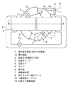
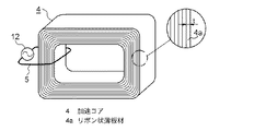
図1は本発明の実施の形態1のビーム加速装置の上面図である。図2は図1のI−I線に沿う矢視断面図である。図3は図2の断面図の偏向電磁石の部分を拡大して示す拡大図である。図4は図3の偏向電磁石の磁極片に巻回された巻線の様子を示す斜視図である。図5は図1のビーム加速装置の加速コアがリボン状薄板材が多層巻きされて作製されている様子を説明する斜視図である。
【0011】
本実施の形態のビーム加速装置は、FFAG型で且つベータトロン加速方式のビーム加速装置である。図1及び図2において、ビーム加速装置は、環状を成す環状真空容器1を有している。環状真空容器1は、ステンレス或いは鉄でなる薄板が接合されて作製され、円形環状をなし内部に断面楔型の密閉空間が形成され、この密閉空間は真空に保持され荷電粒子ビームが通過する環状通路1aとされている。すなわち、環状真空容器1は、荷電粒子ビームが通過する環状通路1aが内部に形成された環状中空容器を構成している。環状通路1aの断面の形状は、径方向において内径側から径方向外側に向かって幅(高さ)が徐々に小さくなる概略楔型を成している。
【0012】
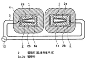
環状真空容器1には、環状真空容器1の円周方向に沿って6個の偏向電磁石2が所定の間隔を空けて等間隔に配設されている。6個の偏向電磁石2は、断面楔型の環状真空容器1を所々で取り囲むようにして設けられている。偏向電磁石2は、環状真空容器1の上下2主面に各々対向する2つの磁極片2a、2bを有している。2つの磁極片2a、2bは、環状真空容器1を挟んで上下に対向して配置され、環状通路1aの内径側から外径側に向かって徐々に間隔を狭めるように設けられている。2つの磁極片2a、2bは中央部でさらに互いに間隔を狭めるように断面形状が中央部で凸の湾曲形状とされている。
【0013】
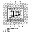
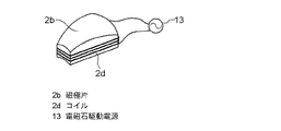
2つの磁極片2a、2bには、図3及び図4に示すように、それぞれコイル2c、2dが巻回されている。2つのコイル2c、2dは、同じ巻回方向で巻かれている。そして、偏向電磁石2は、電源13からコイル2c、2dに電力を供給されて図3に太線矢印で示すような磁力を発生する。一対の磁極片2a、2bの間隔が広がると磁束密度が粗となり磁力が弱くなる。逆に間隔が狭まると磁束密度が密となり磁力が強くなる。つまり、磁場発生手段である偏向電磁石2の作り出す磁場は、半径方向に内径側から外径側に徐々に小から大となる固定の強さの固定磁場である。そのため、偏向電磁石2は固定磁場発生手段でもある。この固定磁場は、荷電粒子の回転に同期させて磁場を内側から外側に移動される変動磁場と逆の関係にあるものである。偏向電磁石2は、この磁場によって荷電粒子ビームの移動方向を所定の曲率半径で偏向させる。そして、偏向電磁石2は、荷電粒子ビームを環状通路1a内の所定の周回軌道上に誘導する。
【0014】
図1に戻り、環状真空容器1の円周方向の一箇所に環状真空容器1を囲繞するように加速ギャップ3が設けられている。加速ギャップ3が設けられた部分の環状真空容器1は、加速電場を発生する為に円周方向に直角な面で分断され、分断箇所は所定の隙間を持って離されている。そして、加速ギャップ3は、セラミック等で作成された短尺円筒状の部材を有し、この円筒部材で該隙間を覆うようにして分断された部分の環状真空容器1を密閉して連結している。そして加速ギャップ3は、このセラミック円筒部材の内側の空間に荷電粒子ビームの加速電場を誘起する。
【0015】
また、環状真空容器1の円周方向の二箇所で該環状真空容器1を取り囲むようにして一対の加速コア4が設けられている。一対の加速コア4は環状真空容器1の中心に対して対象に配置されている。本実施の形態の加速コア4は、図5に示すように、厚さが50μmで飽和磁束密度が1T以上の軟磁性合金でなるリボン状材料4aが多層巻きされて作製されている。2つの加速コア4には、それぞれ加速コア駆動電源12から駆動電流を供給するコイル5が1回巻かれている。
【0016】
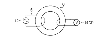
図6は加速コアに係わる電気回路を説明する電気系統図である。各々の加速コア4には、加速コア駆動電源12から非常に強い交流の電流を供給されるコイル5が一巻き巻かれている。2つの加速コア4は環状真空容器1を介して加速ギャップ3と電気的に接続されている。加速コア4はコイル5を介して加速コア駆動電源12から非常に強い交流の電力を供給され内部の磁束を変化させる。この磁束の変化は、電磁誘導の法則にしたがって加速ギャップ3に加速電場を発生させる。
【0017】
図1に戻り、環状真空容器1の所定の位置に、電子を発射する電子銃6が設けられている。電子銃6には、発射された電子を環状真空容器1内に導く静電偏向器7が接続されている。一方、電子ビームの出口8には、電子が加速されてなる高エネルギー電子ビーム9が衝突する位置にX線変換ターゲット10が配置されている。高エネルギー電子ビーム9は、X線変換ターゲット10を通過することによりX線11となる。
【0018】
次にビーム加速装置の動作を示す。電子銃6により生成された電子は、静電偏向器7により環状真空容器1の中の周回軌道に誘導される。電子は偏向電磁石2により生成されたフィールド磁界により偏向され、周回軌道上に閉じこめられる。この周回軌道には加速ギャップ3設けられており、加速コア4内の磁束が変化するとき、電磁誘導の法則により加速ギャップ3に加速電場が発生する。この加速電場によって電子は周回を重ねる毎に加速され、高エネルギー電子ビーム9となる。そして環状真空容器1から引き出される。引き出された高エネルギー電子ビーム9は、X線変換ターゲット10に照射されX線11に変換される。
【0019】
次に加速ギャップ3が誘起する加速電場の印加方法について説明する。本発明に係るビーム加速装置は、ベータトロン加速方式のものであり、加速ギャップ3にかかる交番電界の加速フェーズの間を周回電子が何度も通過することで、該電子は高エネルギーをえる。そして、電子の入射から出射までは、交番電磁界の一周期以内で終了する。
【0020】
加速コア4内部の磁束の変化量はコア材料によって定まる。飽和磁束密度の高いコア材料を用いれば、コア断面積を小さくでき、コア材料も少なくできるので、環状真空容器1の径を小さくすることができ、小型化、低コスト化を図ることができる。本実施の形態においては、高周波で磁束密度が大きく、コア損失の小さい膜厚50μm以下の軟磁性材料を用いることで加速コア4の発熱を抑制する。これにより、加速コア4に印可する励磁周波数を1kHz以上として運転することが可能となる。
【0021】
本実施の形態においては、加速コア4に用いる飽和磁束密度の高い材料として以下の(1)、(2)、(3)いずれかを用いる。これらの材料を用いることで発熱を抑制することができる。
【0022】
(1)鉄系アモルファス
一般式:FeaMbYc(式中、MはTi、V、Cr、Mn、Co、Ni、Zr、Nb、Mo、Hf、Ta、W、Re、Ga、Ru、Rh、Pd、Os、Ir、Pt、希土類元素の群から選ばれた少なくとも1種の元素を、YはSi、B、P、Cの群から選ばれた少なくとも1種の元素を示し、65≦a≦85、0≦b≦15、5≦c≦35、各数字はat%)で実質的に表され、絶縁層を有するもの。
【0023】
(2)鉄系ナノクリスタル
一般式:(Fe1−aMa)100−X−Y−Z−αCuXSiYBZM1α(原子%)(ただし、MはCo及び/又はNiであり、M1はNb、W、Ta、Zr、Hf、Ti及びMoからなる群から選ばれた少なくとも1種の元素であり、a、X、Y、Z及びαはそれぞれ0≦a≦0.5、0.1≦X≦3、0≦Y≦30、0≦Z≦25、5≦Y+Z≦30及び0.1≦α≦30を満たす。)により表される組成を有し、組織の少なくとも50%が1μm以下の平均粒径を有する微細な結晶粒と残部の非晶質、前記結晶粒又は非晶質のいずれかであり、絶縁層を有するFe基軟磁性合金、もしくは、
【0024】
一般式:(Fel−aMa)100−X−Y−Z−α−βCuXSiYBZM1αM2β(原子%)(ただし、MはCo及び/又はNiであり、M1はNb、W、Ta、Zr、Hf、Ti及びMoからなる群から選ばれた少なくとも1種の元素、M2はV、Cr、Mn、Al、白金属元素、S、c、Y、希土類元素、Au、Zn、Sn、Reからなる群から選ばれた少なくとも1種の元素であり、a、X、Y、Z、α及びβはそれぞれ0≦a≦0.5、0.1≦X≦3、0≦Y
≦30、0≦Z≦25、5≦Y+Z≦30、0.1≦α≦30及びβ≦10を満たす。)により表される組成を有し、組織の少なくとも50%が1μm以下の平均粒径を有する微細な結晶粒と残部の非晶質、前記結晶粒又は非晶質のいずれかであり、絶縁層を有するFe基軟磁性合金、もしくは、
【0025】
一般式:(Fe1−aMa)100−X−Y−Z−α−γCuXSiYBZM1αXγ(原子%)(ただし、MはCo及び/又はNiであり、M1はNb、W、Ta、Zr、Hf、Ti及びMoからなる群から選ばれた少なくとも1種の元素、XはC、Ge、P、Ga、Sb、In、Be、Asからなる群から選ばれた少なくとも1種の元素であり、a、X、Y、Z、α及びγはそれぞれ0≦a≦0.5、0.1≦X≦3、0≦Y≦30、0≦Z≦25、5≦Y+Z≦30、0.1≦α≦30及びγ≦10を満たす。)により表される組成を有し、組織の少なくとも50%が1μm以下の平均粒径を有する微細な結晶粒と残部の非晶質、前記結晶粒又は非晶質のいずれかであり、絶縁層を有するFe基軟磁性合金もしくは、(Fe1−aMa)100−X−Y−Z−α−β−γCuXSiYBZM1αM2βXγ(原子%)(ただし、MはCo及び/又はNiであり、M1はNb、W、Ta、Zr、Hf、Ti及びMoからなる群から選ばれた少なくとも1種の元素、M2はV、Cr、Mn、Al、白金属元素、Sc、Y、希土類元素、Au、Zn、Sn、Reからなる群から選ばれた少なくとも1種の元素、XはC、Ge、P、Ga、Sb、In、Be、Asからなる群から選ばれた少なくとも1種の元素であり、a、X、Y、Z、α及びγはそれぞれ0≦a≦0.5、0.1≦X≦3、0≦Y≦30、0≦Z≦25、5≦Y+Z≦30、0.1≦α≦30、β≦10及びγ≦10を満たす。)により表される組成を有し、組織の少なくとも50%が1μm以下の平均粒径を有する微細な結晶粒と残部の非晶質、前記結晶粒又は非晶質のいずれかであり、絶縁層を有するFe基軟磁性合金。
【0026】
(3)絶縁層を有する珪素鋼板もしくは方向性珪素鋼板において、膜厚が50μm以下のもの。
【0027】
ここで、加速コア4に用いる材料の特性を説明する。
まず、膜厚について:
材料の膜厚が厚いほど渦電流損すなわちコア損失が増え、消費電力や発熱が増大し問題となる。本実施の形態で用いた材料の特性図で図7に示す。図7は加速コア4を1Tで励磁した場合について、縦軸に損失、横軸に膜厚をとり、周波数をパラメータと示したものである。
【0028】
図7の結果によれば、膜厚が厚くなるほど曲線の曲がり方が大きくなり、つまり周波数増加に対して損失が急速に増大することが解る。加速電圧Vaccelは、加速コア4の励磁周波数fに比例するので、加速コア4の運転に関しては、電子の加速電圧を高くする目的で、なるべく高周波の励磁周波数にすることが必要となる。そのため、周波数増に対して損失増のゆるやかな膜厚50μm以下の材料を用いることが望ましい。
【0029】
次に、加速コア4の励磁周波数について:
図7に示すように、膜厚を50μm以下とした場合であっても、周波数が1kHzより小さい場合には、損失がほとんど増えない。そのため、実施の形態で用いる軟磁性合金は、励磁周波数が1kHz以上の場合に特に有効となることが解る。
【0030】
次に、飽和磁束密度について:
加速コア4の損失は、また使用磁束密度によって変化する。
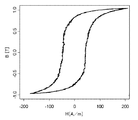
図8に本実施の形態の加速コアの磁束密度−起磁力曲線(BH曲線)を示す。図8において、縦軸は磁束密度B[T]を示し、横軸は起磁力H[A/m]を示す。図8の磁束密度−起磁力曲線において、加速コア4の損失は曲線で囲まれる面積に相当する。従って、低い磁束密度で使用すれば曲線で囲まれる面積が小さくなり、加速コア4の損失を低減することができる。しかし、加速電圧Vaccelは材料の使用磁束密度Bに比例するので、できるだけ高磁束で使用するほうが望ましい。そして実際には図8に示すBH曲線の飽和磁束密度近くまで励磁するのでコア損失も最大となります。この材料の場合Bmaxはほぼ1Tである。このように、1T以上の高磁束密度で使用する場合は高損失となるので、飽和磁束密度が1T以上の軟磁性合金を用いる本実施の形態は特に有効となる。
【0031】
図9は種々の材料について、実用飽和磁束密度と損失を比較した関係図である。損失については、励磁周波数2kHz、磁束密度1Tの場合を示しており、単位はW/kgである。加速コアの小型化を考慮すると、実用飽和磁束密度の低いフェライトが最も不利で、他の材料はほぼ同等である。
【0032】
また、損失の点を考慮すると、鉄系ナノクリスタル、鉄系アモルファス、珪素鋼板(50μm)、珪素鋼板(100μm)の順で良いが、コスト面の点を考慮すると、鉄系ナノクリスタル、鉄系アモルファス、珪素鋼板(50μm)の順で良く、また珪素鋼板(50μm)と珪素鋼板(100μm)とはほぼ同等であることが解る。
【0033】
以上のように、本実施の形態のビーム加速装置においては、加速コア4は、厚さが50μm以下で飽和磁束密度が1T以上の軟磁性合金のリボン状薄板材4aが多層巻きされて作製されている。そのため、コア損失を抑制できるとともに加速コアを小型にすることができる。その結果、ビーム加速装置を小型とすることができ、また、コストの削減を図ることができる。
【0034】
また、加速コア4に印可する励磁周波数を1kHz以上とすることで、加速電圧を増大することができ、高性能なビーム加速装置とすることができる。
【0035】
さらにまた、磁場発生手段(固定磁場発生手段)としての偏向電磁石2は、環状通路1a内に内径側から外径側に徐々に大きくなる固定磁場を生成するので、荷電粒子の回転に同期させて磁場を内側から外側に変動させる必要が無く、しかも軌道を多数回周回する複数の荷電粒子を同時に加速できる。また、偏向電磁石2に電力を供給する電源を、複雑で高価な高周波電源から簡単で安価な一般的な電源にすることができ、コストの削減を図ることができる。
【0036】
さらに、磁場発生手段(固定磁場発生手段)は、環状通路1aを挟んで対向して配置され、環状通路1aの内径側から外径側に向かって徐々に間隔を狭める一対の磁極片2a、2bを有する偏向電磁石2である。そのため、環状通路1a内に内径側から外径側に徐々に大きくなる固定磁場を容易に生成することができる。
【0037】
実施の形態2.
加速コアに関して、コア損失が大きい材料を用いても使用する体積が小さければ総発熱量を抑制できる。このことから、本実施の形態は、ビーム加速装置の大きさに直接係わる環状真空容器が囲む部分の加速コアのみに飽和磁束密度の高い材料を用いるようにして発熱を抑制するものである。
【0038】
図10は本発明の実施の形態2のビーム加速装置を示す加速コアの断面図である。図10において、本実施の形態の加速コア14は、環状真空容器1に囲まれた内部加速コア14aとその他の部分であるコ字型の外部加速コア14bとから構成されている。外部加速コア14bは、厚さ50μm以下の軟磁性合金でなるリボン状材料が実施の形態1と同様に多層巻きされて四角環状の積層体とされた後、四角の1辺部が切り離されて作製される。一方、内部加速コア14aは、外部加速コア14bに用いられる材料より飽和磁束密度が高く、厚さ5.0μm以上の軟磁性合金でなるリボン状材料が多数枚積層されて作製される。そして、1個の内部加速コア14aと2個の外部加速コア14bとが接合されて、断面概略めがね状の環状真空容器1を2箇所で囲む一対の加速コア14とされている。
【0039】
尚、外部加速コア14bと内部加速コア14aの接合においては、接合部が約45°に形成され、接合面は所定の程度の鏡面仕上げによって磨かれ、両接合面は、例えば接着剤にて接合される。上述にて接合面が磨かれる理由は、両接合面間に含浸する接着剤層を微少な厚さとすることであり、接着剤層が所定の厚さ以下であれば、加速コア14内に磁束が良好に発生する。
【0040】
また、外部加速コア14bと内部加速コア14aは、外部加速コア14bの飽和磁束密度Boと、内部加速コア14aの飽和磁束密度Biとの比が、内部加速コア14aの断面積Sdと、内部加速コア14aと外部加速コア14bの接合面積Ssの比と等しくなるように(Bo:Bi=Sd:Ss)されている。このように接合することで、両者の飽和磁束密度のしきい値を同じとすることができ、内部加速コア14a及び外部加速コア14bを共に、飽和磁束密度に安全係数(通常0.7〜0.9)をかけた値で使用することができる。尚、接合面積Ssの調整は、接合面の傾きを変化されることにより行うことができる。
【0041】
本実施の形態においては、内部加速コア14aの飽和磁束密度が高いため、必要な磁束を得るためのコア断面積を小さくすることができ、ビーム加速装置を小型・軽量化することができ、コストダウンを図ることができる。一方、内部加速コア14aの体積は、加速コア全体の1/4〜1/5に過ぎないため、発熱の総量を抑制することができる。
【0042】
このような構成のビーム加速装置においては、加速コア14は、環状真空容器1の内側側面によって径方向内側に囲まれる部分の内部加速コア14aとこの内部加速コア14aとともに環を成す断面コ字型の外部加速コア14bを有し、内部加速コア14aは外部加速コア14bよりも飽和磁束密度の高い軟磁性合金で作製されている。すなわち、加速コア14の環状真空容器1で囲まれた部分に飽和磁束密度の高い軟磁性合金を用い、その他の部分にコア損失の小さい軟磁性合金を用いることにより、加速コア14の全体での損失(発熱)を抑制することができ、電源負荷の低減、冷却構造の簡素化ができると同時に、コストを増加させることなく加速コアを小型にすることができる。
尚、本実施の形態においては、偏向電磁石2のような固定磁場発生手段に限らず、その他の磁場発生手段、例えば変動磁場発生手段等においても同様な効果を得ることができる。
【0043】
【発明の効果】
この発明に係るビーム加速装置は、荷電粒子ビームが通過する環状通路が内部に形成された環状中空容器と、環状中空容器の円周方向に沿って複数個設けられ荷電粒子ビームを偏向させて荷電粒子ビームを環状通路内の周回軌道上に誘導する固定磁場発生手段と、環状中空容器の所定の位置に設けられ荷電粒子ビームの加速電場を誘起する加速ギャップと、環状中空容器を取り囲むように設けられ内部の磁束を変化させて電磁誘導により加速ギャップを介して加速電場を発生する加速コアとを備え、加速コアに印可する励磁周波数の1周期以内に荷電粒子の入射から出射までを完了するビーム加速装置であって、加速コアは、厚さが50μm以下で飽和磁束密度が1T以上の軟磁性合金のリボン状薄板材が多層巻きされて作製されている。そのため、コア損失を抑制できるとともに加速コアを小型にすることができる。その結果、ビーム加速装置を小型とすることができ、また、コストの削減を図ることができる。
【図面の簡単な説明】
【図1】 本発明の実施の形態1のビーム加速装置の上面図である。
【図2】 図1のI−I線に沿う矢視断面図である。
【図3】 図2の断面図の偏向電磁石の部分を拡大して示す拡大図である。
【図4】 図3の偏向電磁石の磁極片に巻回された巻線の様子を示す斜視図である。
【図5】 実施の形態1のビーム加速装置の加速コアがリボン状薄板材が多層巻きされて作製されている様子を説明する斜視図である。
【図6】 図5の加速コアに係わる電気回路を説明する電気系統図である。
【図7】 実施の形態1の材料膜厚との特性図である。
【図8】 実施の形態1の加速コアの磁束密度−起磁力曲線を示す関係図である。
【図9】 種々の材料について実用飽和磁束密度と損失を比較した関係図である。
【図10】 本発明の実施の形態2のビーム加速装置を示す加速コアの断面図である。
【符号の説明】
1 環状真空容器(環状中空容器)、1a 環状通路、2 偏向電磁石(磁場発生手段)、2a,2b 磁極片、3 加速ギャップ、4,14 加速コア、5コイル、6 電子銃、7 静電偏向器、8 出口、9 高エネルギー電子ビーム、10 X線変換ターゲット、11 X線、12 加速コア駆動電源、13 偏向電磁石駆動電源、14a 内部加速コア、14b 外部加速コア。[0001]
BACKGROUND OF THE INVENTION
The present invention relates to a beam accelerator for generating high-energy X-rays or high-energy charged particle beams used for cancer treatment or sterilization, and more particularly to a FFAG type using a fixed magnetic field as a means for deflecting charged particle beams. The present invention relates to a beam accelerator of a circular magnetic induction (betatron) acceleration type.
[0002]
[Prior art]
The beam accelerator is for accelerating charged particles such as electrons. Then, the accelerated charged particles are irradiated to an X-ray conversion target such as copper or tungsten to generate an X-ray, and the X-ray is irradiated to the affected area to perform cancer treatment, sterilization, or the like. The beam accelerator according to the present invention is a FFAG (Fixed Field Alternating Gradient) type beam accelerator using a fixed magnetic field as a means for deflecting a charged particle beam, and has a feature of small size and high output. The FFAG type beam accelerator for electron acceleration is only a prototype in the US MURA (Midwestern Universities Research Association) (for example, refer nonpatent literature 1).
[0003]
An output current limiting condition of a conventional FFAG type beam accelerator will be described. When the electron beam current is increased, the electron beam diverges in a region that is not sufficiently accelerated (low energy region), so that efficient acceleration is difficult. In order to suppress this divergence, the acceleration voltage is increased and acceleration is performed at an early point, and a high energy beam may be formed before divergence. That is, the acceleration voltage proportional to the time change of the magnetic flux may be increased. To do this, it is necessary to increase the excitation frequency applied to the acceleration core.
[0004]
[Non-Patent Document 1]
FT Cole, 4 others, “THE REVIEW OF SCIENTIFIC INSTRUMENTS, Volume 28 (Vo1.28) Number 6 (Num.6)”, (US), American Institute of Physics, 1957, p. 403-420
[0005]
[Problems to be solved by the invention]
However, in the FFAG type and betatron acceleration type beam accelerator, the excitation frequency applied to the acceleration core is conventionally limited to about several hundred Hz. This is due to the material used for the acceleration core. For example, a silicon steel sheet having a film thickness of about 100 μm, which has been used for an acceleration core in the past, has a high saturation magnetic flux density, but has a large core loss and large heat generation. Therefore, operation at a high excitation frequency (1 kHz or more) has been difficult.
[0006]
The amount of change in the internal magnetic flux of the acceleration core is determined by the product of the saturation magnetic flux density determined by the material and the cross-sectional area of the core. If a core material having a high saturation magnetic flux density is used, the core cross-sectional area can be reduced, the material can be reduced, and the apparatus can be downsized. However, a material with a high saturation magnetic flux density generally has a large core loss and a large amount of heat generation. As a result, there is a problem that the core cross-sectional area becomes large and the apparatus becomes large.
[0007]
That is, in such a FFAG type and betatron acceleration type beam accelerator, when the excitation frequency applied to the acceleration core is set to 1 kHz or more, a high-saturation magnetic flux density material having a high loss is used from the point of temperature rise. There was a problem that the acceleration core became large. Or, conversely, when high saturation magnetic flux density material (silicon steel plate having a film thickness of 100 μm or more) is used with emphasis on downsizing, the excitation frequency applied to the acceleration core must be operated at less than 1 kHz, There was a problem that sufficient output could not be obtained.
[0008]
The present invention has been made to solve the above-mentioned problems, and is capable of increasing the acceleration voltage by suppressing the heat generation of the acceleration core and increasing the excitation frequency applied to the acceleration core. To obtain a simple beam accelerator. It is another object of the present invention to obtain a beam accelerator that is small in size and capable of reducing costs.
[0009]
[Means for Solving the Problems]
The beam accelerator according to the present invention includes an annular hollow container in which an annular passage through which a charged particle beam passes is formed, and a plurality of provided along the circumferential direction of the annular hollow container. Fixed magnetic field generating means for guiding the particle beam onto the circular orbit in the annular passage, an acceleration gap for inducing an accelerating electric field of the charged particle beam at a predetermined position of the annular hollow container, and surrounding the annular hollow container And an accelerating core that generates an accelerating electric field through an accelerating gap by electromagnetic induction by changing the internal magnetic flux, and completes from charged particle incidence to emission within one cycle of the excitation frequency applied to the accelerating core. In the acceleration device, the acceleration core is manufactured by winding a ribbon-like thin plate material of a soft magnetic alloy having a thickness of 50 μm or less and a saturation magnetic flux density of 1 T or more in multiple layers.
[0010]
DETAILED DESCRIPTION OF THE INVENTION
FIG. 1 is a top view of a beam accelerator according to
[0011]
The beam accelerator of this embodiment is a FFAG type and a betatron acceleration type beam accelerator. 1 and 2, the beam accelerator has an
[0012]
In the
[0013]
As shown in FIGS. 3 and 4,
[0014]
Returning to FIG. 1, an
[0015]
A pair of
[0016]
FIG. 6 is an electrical system diagram illustrating an electrical circuit related to the acceleration core. Each of the
[0017]
Returning to FIG. 1, an
[0018]
Next, the operation of the beam accelerator will be described. Electrons generated by the
[0019]
Next, a method for applying an acceleration electric field induced by the
[0020]
The amount of change in the magnetic flux inside the
[0021]
In the present embodiment, any of the following (1), (2), and (3) is used as a material having a high saturation magnetic flux density used for the
[0022]
(1) Iron-based amorphous
General formula: FeaMbYc (wherein M is Ti, V, Cr, Mn, Co, Ni, Zr, Nb, Mo, Hf, Ta, W, Re, Ga, Ru, Rh, Pd, Os, Ir, Pt, At least one element selected from the group of rare earth elements, Y represents at least one element selected from the group of Si, B, P, and C, 65 ≦ a ≦ 85, 0 ≦ b ≦ 15, 5 ≦ c ≦ 35, each number is substantially expressed as at%), and has an insulating layer.
[0023]
(2) Iron-based nanocrystals
General formula: (Fe1-aMa) 100-XYZ-αCuXSiYBZM1α (atomic%) (where M is Co and / or Ni, and M1 is from Nb, W, Ta, Zr, Hf, Ti and Mo) A, X, Y, Z and α are 0 ≦ a ≦ 0.5, 0.1 ≦ X ≦ 3, 0 ≦ Y ≦ 30, and 0 ≦ Z, respectively. ≦ 25, 5 ≦ Y + Z ≦ 30 and 0.1 ≦ α ≦ 30), and at least 50% of the structure has fine crystal grains having an average grain size of 1 μm or less and the balance Amorphous, either the crystal grain or amorphous, Fe-based soft magnetic alloy having an insulating layer, or
[0024]
General formula: (Fel-aMa) 100-XY-Z-α-βCuXSiYBZM1αM2β (atomic%) (where M is Co and / or Ni, M1 is Nb, W, Ta, Zr, Hf, Ti and At least one element selected from the group consisting of Mo, M2 is selected from the group consisting of V, Cr, Mn, Al, white metal elements, S, c, Y, rare earth elements, Au, Zn, Sn, Re A, X, Y, Z, α, and β are 0 ≦ a ≦ 0.5, 0.1 ≦ X ≦ 3, and 0 ≦ Y, respectively.
≦ 30, 0 ≦ Z ≦ 25, 5 ≦ Y + Z ≦ 30, 0.1 ≦ α ≦ 30 and β ≦ 10 are satisfied. ), And at least 50% of the structure has fine crystal grains having an average grain size of 1 μm or less and the remaining amorphous, either the crystal grains or amorphous, and an insulating layer Fe-based soft magnetic alloy having, or
[0025]
General formula: (Fe1-aMa) 100-XYZ-α-γCuXSiYBZM1αXγ (atomic%) (where M is Co and / or Ni, M1 is Nb, W, Ta, Zr, Hf, Ti and At least one element selected from the group consisting of Mo, X is at least one element selected from the group consisting of C, Ge, P, Ga, Sb, In, Be, As, and a, X, Y, Z, α and γ are 0 ≦ a ≦ 0.5, 0.1 ≦ X ≦ 3, 0 ≦ Y ≦ 30, 0 ≦ Z ≦ 25, 5 ≦ Y + Z ≦ 30, 0.1 ≦ α ≦ 30, respectively. And γ ≦ 10), and at least 50% of the structure has fine crystal grains having an average grain size of 1 μm or less and the remaining amorphous, the crystal grains or amorphous Either an Fe-based soft magnetic alloy having an insulating layer or (Fe1-aMa) 10 -X-Y-Z- [alpha]-[beta]-[gamma] CuXSiYBZM1 [alpha] M2 [beta] X [gamma] (atomic%) (where M is Co and / or Ni, and M1 is selected from the group consisting of Nb, W, Ta, Zr, Hf, Ti and Mo) At least one element, M2 is at least one element selected from the group consisting of V, Cr, Mn, Al, white metal element, Sc, Y, rare earth element, Au, Zn, Sn, Re, and X is It is at least one element selected from the group consisting of C, Ge, P, Ga, Sb, In, Be, As, and a, X, Y, Z, α, and γ are 0 ≦ a ≦ 0.5, respectively. 0.1 ≦ X ≦ 3, 0 ≦ Y ≦ 30, 0 ≦ Z ≦ 25, 5 ≦ Y + Z ≦ 30, 0.1 ≦ α ≦ 30, β ≦ 10, and γ ≦ 10. Fine crystal grains having a composition and at least 50% of the structure having an average grain size of 1 μm or less Amorphous balance, the is a grain or amorphous either, Fe-based soft magnetic alloy having an insulating layer.
[0026]
(3) A silicon steel sheet or a directional silicon steel sheet having an insulating layer and having a thickness of 50 μm or less.
[0027]
Here, the characteristic of the material used for the
First, about film thickness:
As the film thickness of the material increases, eddy current loss, that is, core loss increases, and power consumption and heat generation increase, which becomes a problem. FIG. 7 is a characteristic diagram of materials used in this embodiment mode. FIG. 7 shows the case where the
[0028]
According to the result of FIG. 7, it can be understood that as the film thickness is increased, the curve is bent more rapidly, that is, the loss is rapidly increased as the frequency is increased. Since the acceleration voltage Vaccel is proportional to the excitation frequency f of the
[0029]
Next, regarding the excitation frequency of the acceleration core 4:
As shown in FIG. 7, even when the film thickness is 50 μm or less, the loss hardly increases when the frequency is smaller than 1 kHz. Therefore, it can be seen that the soft magnetic alloy used in the embodiment is particularly effective when the excitation frequency is 1 kHz or more.
[0030]
Next, about saturation magnetic flux density:
The loss of the accelerating
FIG. 8 shows a magnetic flux density-magnetomotive force curve (BH curve) of the acceleration core of the present embodiment. In FIG. 8, the vertical axis indicates the magnetic flux density B [T], and the horizontal axis indicates the magnetomotive force H [A / m]. In the magnetic flux density-magnetomotive force curve of FIG. 8, the loss of the
[0031]
FIG. 9 is a relational diagram comparing practical saturation magnetic flux density and loss for various materials. Regarding the loss, the case of
[0032]
In consideration of loss, iron-based nanocrystal, iron-based amorphous, silicon steel plate (50 μm), silicon steel plate (100 μm) may be used in this order. However, considering cost, iron-based nanocrystal, iron-based It is understood that the order is amorphous and silicon steel plate (50 μm), and that the silicon steel plate (50 μm) and the silicon steel plate (100 μm) are almost equivalent.
[0033]
As described above, in the beam accelerator of the present embodiment, the accelerating
[0034]
In addition, by setting the excitation frequency applied to the
[0035]
Furthermore, the deflecting
[0036]
Further, the magnetic field generating means (fixed magnetic field generating means) are arranged to face each other with the
[0037]
Regarding the acceleration core, even if a material having a large core loss is used, the total heat generation amount can be suppressed if the volume used is small. For this reason, in this embodiment, heat generation is suppressed by using a material having a high saturation magnetic flux density only for the portion of the acceleration core surrounded by the annular vacuum vessel directly related to the size of the beam accelerator.
[0038]
FIG. 10 is a cross-sectional view of an acceleration core showing a beam accelerator according to
[0039]
In the joining of the
[0040]
Further, the
[0041]
In the present embodiment, since the saturation magnetic flux density of the
[0042]
In the beam accelerator having such a configuration, the
In the present embodiment, the same effect can be obtained not only in the fixed magnetic field generating means such as the deflecting
[0043]
【The invention's effect】
The beam accelerator according to the present invention includes an annular hollow container in which an annular passage through which a charged particle beam passes is formed, and a plurality of provided along the circumferential direction of the annular hollow container. Fixed magnetic field generating means for guiding the particle beam onto the circular orbit in the annular passage, an acceleration gap for inducing an accelerating electric field of the charged particle beam at a predetermined position of the annular hollow container, and surrounding the annular hollow container And an accelerating core that generates an accelerating electric field through an accelerating gap by electromagnetic induction by changing the internal magnetic flux, and completes from charged particle incidence to emission within one cycle of the excitation frequency applied to the accelerating core. In the acceleration device, the acceleration core is manufactured by winding a ribbon-like thin plate material of a soft magnetic alloy having a thickness of 50 μm or less and a saturation magnetic flux density of 1 T or more in multiple layers. Therefore, the core loss can be suppressed and the acceleration core can be reduced in size. As a result, the beam accelerator can be reduced in size and cost can be reduced.
[Brief description of the drawings]
FIG. 1 is a top view of a beam accelerator according to a first embodiment of the present invention.
FIG. 2 is a cross-sectional view taken along the line II in FIG.
3 is an enlarged view showing an enlarged portion of the bending electromagnet in the cross-sectional view of FIG. 2;
4 is a perspective view showing a state of a winding wound around a magnetic pole piece of the deflection electromagnet of FIG. 3. FIG.
FIG. 5 is a perspective view for explaining a state in which the acceleration core of the beam accelerator according to the first embodiment is manufactured by winding a ribbon-like thin plate material in multiple layers.
6 is an electrical system diagram for explaining an electrical circuit related to the acceleration core of FIG. 5;
FIG. 7 is a characteristic diagram with the material film thickness in the first embodiment.
FIG. 8 is a relationship diagram illustrating a magnetic flux density-magnetomotive force curve of the acceleration core according to the first embodiment.
FIG. 9 is a relational diagram comparing practical saturation magnetic flux density and loss for various materials.
FIG. 10 is a sectional view of an acceleration core showing a beam accelerator according to a second embodiment of the present invention.
[Explanation of symbols]
1 annular vacuum vessel (annular hollow vessel), 1a annular passage, 2 deflection electromagnets (magnetic field generating means), 2a, 2b pole piece, 3 acceleration gap, 4,14 acceleration core, 5 coils, 6 electron gun, 7
Claims (6)
前記環状中空容器の円周方向に沿って複数個設けられ前記荷電粒子ビームを偏向させて該荷電粒子ビームを前記環状通路内の周回軌道上に誘導する固定磁場発生手段と、
前記環状中空容器の所定の位置に設けられ前記荷電粒子ビームの加速電場を誘起する加速ギャップと、
前記環状中空容器を取り囲むように設けられ内部の磁束を変化させて電磁誘導により前記加速ギャップを介して前記加速電場を発生する加速コアとを備え、
前記加速コアに印可する励磁周波数の1周期以内に荷電粒子の入射から出射までを完了するビーム加速装置であって、
前記加速コアは、厚さが50μm以下で飽和磁束密度が1T以上の軟磁性合金のリボン状薄板材が多層巻きされて作製されている
ことを特徴とするビーム加速装置。An annular hollow container in which an annular passage through which a charged particle beam passes is formed;
A plurality of fixed magnetic field generating means provided along a circumferential direction of the annular hollow container for deflecting the charged particle beam and guiding the charged particle beam onto a circular orbit in the annular passage;
An acceleration gap that is provided at a predetermined position of the annular hollow container and induces an acceleration electric field of the charged particle beam;
An accelerating core that is provided so as to surround the annular hollow container and generates the accelerating electric field through the accelerating gap by electromagnetic induction by changing an internal magnetic flux;
A beam accelerator that completes from the entrance to the exit of charged particles within one cycle of the excitation frequency applied to the acceleration core,
The acceleration core is produced by winding a ribbon-like thin plate material of a soft magnetic alloy having a thickness of 50 μm or less and a saturation magnetic flux density of 1 T or more.
前記環状中空容器の円周方向に沿って複数個設けられ前記荷電粒子ビームを偏向させて該荷電粒子ビームを前記環状通路内の周回軌道上に誘導する磁場発生手段と、
前記環状中空容器の所定の位置に設けられ前記荷電粒子ビームの加速電場を誘起する加速ギャップと、
前記環状中空容器を取り囲むように設けられ内部の磁束を変化させて電磁誘導により前記加速ギャップを介して前記加速電場を発生する加速コアとを備え、
前記加速コアに印可する励磁周波数の1周期以内に荷電粒子の入射から出射までを完了するビーム加速装置であって、
前記加速コアは、前記環状中空容器の内側側面によって径方向内側に囲まれる部分の内部加速コアと、該内部加速コアとともに環を成す断面コ字型の外部加速コアとを有し、前記内部加速コアは該外部加速コアよりも飽和磁束密度の高い軟磁性合金で作製されている
ことを特徴とするビーム加速装置。An annular hollow container in which an annular passage through which a charged particle beam passes is formed;
A plurality of magnetic field generating means provided along a circumferential direction of the annular hollow container for deflecting the charged particle beam and guiding the charged particle beam onto a circular orbit in the annular passage;
An acceleration gap that is provided at a predetermined position of the annular hollow container and induces an acceleration electric field of the charged particle beam;
An accelerating core that is provided so as to surround the annular hollow container and generates the accelerating electric field through the accelerating gap by electromagnetic induction by changing an internal magnetic flux;
A beam accelerator that completes from the entrance to the exit of charged particles within one cycle of the excitation frequency applied to the acceleration core,
The acceleration core includes a portion of an internal acceleration core surrounded by a radially inner side by an inner side surface of the annular hollow container, and an external acceleration core having a U-shaped cross section that forms a ring with the internal acceleration core. A beam accelerator characterized in that the core is made of a soft magnetic alloy having a saturation magnetic flux density higher than that of the external acceleration core.
ことを特徴とする請求項2に記載のビーム加速装置。In the external acceleration core and the internal acceleration core, the ratio of the saturation magnetic flux density of the external acceleration core to the saturation magnetic flux density of the internal acceleration core is such that the cross-sectional area of the internal acceleration core and the internal acceleration core and the external acceleration core The beam acceleration device according to claim 2, wherein the beam acceleration device is equal to the ratio of the junction area of the beam accelerator.
ことを特徴とする請求項1から3のいずれかに記載のビーム加速装置。The beam acceleration apparatus according to any one of claims 1 to 3, wherein an excitation frequency of the acceleration core is 1 kHz or more.
ことを特徴とする請求項1から4のいずれかに記載のビーム加速装置。The beam according to any one of claims 1 to 4, wherein the fixed magnetic field generating means or the magnetic field generating means generates a fixed magnetic field that gradually increases from the inner diameter side to the outer diameter side in the annular passage. Accelerator.
ことを特徴とする請求項5に記載のビーム加速装置。The fixed magnetic field generating means or the magnetic field generating means is an electromagnet that is disposed to face each other with the annular passage interposed therebetween, and has a pair of magnetic pole pieces that gradually narrows the interval from the inner diameter side to the outer diameter side of the annular passage. The beam accelerator according to claim 5, wherein the beam accelerator is provided.
Priority Applications (2)
| Application Number | Priority Date | Filing Date | Title |
|---|---|---|---|
| JP2002302684A JP3961925B2 (en) | 2002-10-17 | 2002-10-17 | Beam accelerator |
| US10/417,218 US6713976B1 (en) | 2002-10-17 | 2003-04-17 | Beam accelerator |
Applications Claiming Priority (1)
| Application Number | Priority Date | Filing Date | Title |
|---|---|---|---|
| JP2002302684A JP3961925B2 (en) | 2002-10-17 | 2002-10-17 | Beam accelerator |
Publications (2)
| Publication Number | Publication Date |
|---|---|
| JP2004139812A JP2004139812A (en) | 2004-05-13 |
| JP3961925B2 true JP3961925B2 (en) | 2007-08-22 |
Family
ID=31987232
Family Applications (1)
| Application Number | Title | Priority Date | Filing Date |
|---|---|---|---|
| JP2002302684A Expired - Lifetime JP3961925B2 (en) | 2002-10-17 | 2002-10-17 | Beam accelerator |
Country Status (2)
| Country | Link |
|---|---|
| US (1) | US6713976B1 (en) |
| JP (1) | JP3961925B2 (en) |
Families Citing this family (60)
| Publication number | Priority date | Publication date | Assignee | Title |
|---|---|---|---|---|
| JP2003031172A (en) * | 2001-07-16 | 2003-01-31 | Nikon Corp | Deflector and manufacturing method of the same, and charged particle exposing device |
| EP2259664B1 (en) | 2004-07-21 | 2017-10-18 | Mevion Medical Systems, Inc. | A programmable radio frequency waveform generator for a synchrocyclotron |
| US20060017010A1 (en) * | 2004-07-22 | 2006-01-26 | Axcelis Technologies, Inc. | Magnet for scanning ion beams |
| US7957507B2 (en) | 2005-02-28 | 2011-06-07 | Cadman Patrick F | Method and apparatus for modulating a radiation beam |
| US8232535B2 (en) | 2005-05-10 | 2012-07-31 | Tomotherapy Incorporated | System and method of treating a patient with radiation therapy |
| US8442287B2 (en) | 2005-07-22 | 2013-05-14 | Tomotherapy Incorporated | Method and system for evaluating quality assurance criteria in delivery of a treatment plan |
| CN101267857A (en) | 2005-07-22 | 2008-09-17 | 断层放疗公司 | System and method of delivering radiation therapy to a moving region of interest |
| CA2616292A1 (en) * | 2005-07-22 | 2007-02-01 | Tomotherapy Incorporated | Method and system for evaluating quality assurance criteria in delivery of a treament plan |
| CA2616306A1 (en) * | 2005-07-22 | 2007-02-01 | Tomotherapy Incorporated | Method and system for processing data relating to a radiation therapy treatment plan |
| EP1906826A4 (en) * | 2005-07-22 | 2009-10-21 | Tomotherapy Inc | System and method of detecting a breathing phase of a patient receiving radiation therapy |
| US7643661B2 (en) * | 2005-07-22 | 2010-01-05 | Tomo Therapy Incorporated | Method and system for evaluating delivered dose |
| CA2616280A1 (en) * | 2005-07-22 | 2007-02-01 | Tomotherapy Incorporated | System and method of remotely analyzing operation of a radiation therapy system |
| WO2007014092A2 (en) * | 2005-07-22 | 2007-02-01 | Tomotherapy Incorporated | Method of placing constraints on a deformation map and system for implementing same |
| CA2616136A1 (en) * | 2005-07-22 | 2007-02-01 | Tomotherapy Incorporated | System and method of evaluating dose delivered by a radiation therapy system |
| US7574251B2 (en) * | 2005-07-22 | 2009-08-11 | Tomotherapy Incorporated | Method and system for adapting a radiation therapy treatment plan based on a biological model |
| AU2006272730A1 (en) * | 2005-07-22 | 2007-02-01 | Tomotherapy Incorporated | Method of and system for predicting dose delivery |
| CN101267767A (en) * | 2005-07-23 | 2008-09-17 | 断层放疗公司 | Radiation therapy imaging and delivery utilizing coordinated motion of gantry and couch |
| JP4485437B2 (en) * | 2005-09-08 | 2010-06-23 | 三菱電機株式会社 | High-frequency accelerating cavity and circular accelerator |
| EP2389981A3 (en) | 2005-11-18 | 2012-03-07 | Still River Systems, Inc. | Charged particle radiation therapy |
| JP4513756B2 (en) * | 2006-02-06 | 2010-07-28 | 三菱電機株式会社 | Electromagnetic wave generator |
| US7809441B2 (en) * | 2006-05-17 | 2010-10-05 | Cardiac Pacemakers, Inc. | Implantable medical device with chemical sensor and related methods |
| US20080043910A1 (en) * | 2006-08-15 | 2008-02-21 | Tomotherapy Incorporated | Method and apparatus for stabilizing an energy source in a radiation delivery device |
| US7928672B2 (en) * | 2007-09-19 | 2011-04-19 | Schlumberger Technology Corporation | Modulator for circular induction accelerator |
| WO2009048931A1 (en) * | 2007-10-09 | 2009-04-16 | Passport Systems, Inc. | A method for achieving high duty cycle operation and multiple beams with weak focusing and fixed field alternating gradient induction accelerators |
| US8063356B1 (en) | 2007-12-21 | 2011-11-22 | Schlumberger Technology Corporation | Method of extracting formation density and Pe using a pulsed accelerator based litho-density tool |
| US8581523B2 (en) | 2007-11-30 | 2013-11-12 | Mevion Medical Systems, Inc. | Interrupted particle source |
| US8933650B2 (en) * | 2007-11-30 | 2015-01-13 | Mevion Medical Systems, Inc. | Matching a resonant frequency of a resonant cavity to a frequency of an input voltage |
| US8321131B2 (en) * | 2007-12-14 | 2012-11-27 | Schlumberger Technology Corporation | Radial density information from a Betatron density sonde |
| US8035321B2 (en) * | 2007-12-14 | 2011-10-11 | Schlumberger Technology Corporation | Injector for betatron |
| US8311186B2 (en) * | 2007-12-14 | 2012-11-13 | Schlumberger Technology Corporation | Bi-directional dispenser cathode |
| US7916838B2 (en) * | 2007-12-14 | 2011-03-29 | Schlumberger Technology Corporation | Betatron bi-directional electron injector |
| US7638957B2 (en) * | 2007-12-14 | 2009-12-29 | Schlumberger Technology Corporation | Single drive betatron |
| US8169167B2 (en) * | 2008-01-09 | 2012-05-01 | Passport Systems, Inc. | Methods for diagnosing and automatically controlling the operation of a particle accelerator |
| WO2009089441A1 (en) * | 2008-01-09 | 2009-07-16 | Passport Systems, Inc. | Methods and systems for accelerating particles using induction to generate an electric field with a localized curl |
| EP2232959A4 (en) * | 2008-01-09 | 2015-04-08 | Passport Systems Inc | Diagnostic methods and apparatus for an accelerator using induction to generate an electric field with a localized curl |
| US8138677B2 (en) * | 2008-05-01 | 2012-03-20 | Mark Edward Morehouse | Radial hall effect ion injector with a split solenoid field |
| US8362717B2 (en) * | 2008-12-14 | 2013-01-29 | Schlumberger Technology Corporation | Method of driving an injector in an internal injection betatron |
| JP5565798B2 (en) * | 2010-03-30 | 2014-08-06 | 大学共同利用機関法人 高エネルギー加速器研究機構 | Bending electromagnet system with acceleration function |
| TW201433331A (en) | 2012-09-28 | 2014-09-01 | Mevion Medical Systems Inc | Adjusting coil position |
| US9681531B2 (en) | 2012-09-28 | 2017-06-13 | Mevion Medical Systems, Inc. | Control system for a particle accelerator |
| US10254739B2 (en) | 2012-09-28 | 2019-04-09 | Mevion Medical Systems, Inc. | Coil positioning system |
| JP6254600B2 (en) | 2012-09-28 | 2017-12-27 | メビオン・メディカル・システムズ・インコーポレーテッド | Particle accelerator |
| US9622335B2 (en) | 2012-09-28 | 2017-04-11 | Mevion Medical Systems, Inc. | Magnetic field regenerator |
| CN104813749B (en) | 2012-09-28 | 2019-07-02 | 梅维昂医疗系统股份有限公司 | Control the intensity of the particle beams |
| TW201422279A (en) | 2012-09-28 | 2014-06-16 | Mevion Medical Systems Inc | Focusing a particle beam |
| TW201438787A (en) | 2012-09-28 | 2014-10-16 | Mevion Medical Systems Inc | Controlling particle therapy |
| CN104812444B (en) | 2012-09-28 | 2017-11-21 | 梅维昂医疗系统股份有限公司 | The energy adjustment of the particle beams |
| EP2962309B1 (en) | 2013-02-26 | 2022-02-16 | Accuray, Inc. | Electromagnetically actuated multi-leaf collimator |
| US8791656B1 (en) | 2013-05-31 | 2014-07-29 | Mevion Medical Systems, Inc. | Active return system |
| US9730308B2 (en) | 2013-06-12 | 2017-08-08 | Mevion Medical Systems, Inc. | Particle accelerator that produces charged particles having variable energies |
| CN110237447B (en) | 2013-09-27 | 2021-11-02 | 梅维昂医疗系统股份有限公司 | Particle therapy system |
| US9962560B2 (en) | 2013-12-20 | 2018-05-08 | Mevion Medical Systems, Inc. | Collimator and energy degrader |
| US10675487B2 (en) | 2013-12-20 | 2020-06-09 | Mevion Medical Systems, Inc. | Energy degrader enabling high-speed energy switching |
| US9661736B2 (en) | 2014-02-20 | 2017-05-23 | Mevion Medical Systems, Inc. | Scanning system for a particle therapy system |
| US9950194B2 (en) | 2014-09-09 | 2018-04-24 | Mevion Medical Systems, Inc. | Patient positioning system |
| US10786689B2 (en) | 2015-11-10 | 2020-09-29 | Mevion Medical Systems, Inc. | Adaptive aperture |
| US10925147B2 (en) | 2016-07-08 | 2021-02-16 | Mevion Medical Systems, Inc. | Treatment planning |
| US11103730B2 (en) | 2017-02-23 | 2021-08-31 | Mevion Medical Systems, Inc. | Automated treatment in particle therapy |
| EP3645111A1 (en) | 2017-06-30 | 2020-05-06 | Mevion Medical Systems, Inc. | Configurable collimator controlled using linear motors |
| WO2020185544A1 (en) | 2019-03-08 | 2020-09-17 | Mevion Medical Systems, Inc. | Delivery of radiation by column and generating a treatment plan therefor |
Family Cites Families (1)
| Publication number | Priority date | Publication date | Assignee | Title |
|---|---|---|---|---|
| US5811943A (en) * | 1996-09-23 | 1998-09-22 | Schonberg Research Corporation | Hollow-beam microwave linear accelerator |
-
2002
- 2002-10-17 JP JP2002302684A patent/JP3961925B2/en not_active Expired - Lifetime
-
2003
- 2003-04-17 US US10/417,218 patent/US6713976B1/en not_active Expired - Lifetime
Also Published As
| Publication number | Publication date |
|---|---|
| US6713976B1 (en) | 2004-03-30 |
| JP2004139812A (en) | 2004-05-13 |
Similar Documents
| Publication | Publication Date | Title |
|---|---|---|
| JP3961925B2 (en) | Beam accelerator | |
| US7506566B2 (en) | Bulk stamped amorphous metal magnetic component | |
| KR100442990B1 (en) | Systems and Methods for Generating Nested Static and Time-Varying Magnetic Fields | |
| US20010043134A1 (en) | Bulk stamped amorphous metal magnetic component | |
| JPH1126198A (en) | Electromagnet, accelerator and magnetic field generator | |
| WO2004039133A1 (en) | Electron accelerator and radiotherapy apparatus using same | |
| JP4422057B2 (en) | Electromagnet and accelerator system | |
| JPH02184002A (en) | Magnetic field generator for mri | |
| JP4061166B2 (en) | Core unit of charged particle accelerator | |
| JP3102784B2 (en) | Magnetic field variable magnet | |
| JP4066351B2 (en) | Electromagnet for fixed magnetic field alternating gradient accelerator | |
| JP4106286B2 (en) | Betatron accelerator | |
| JP2935082B2 (en) | Normal conducting magnet type electron storage ring | |
| JP2533705B2 (en) | Electromagnet device | |
| JPH0394733A (en) | Magnetic field generator for mri | |
| JPH03141615A (en) | Solid mass iron core electromagnet | |
| JPH04316305A (en) | Iron core structure of electromagnet | |
| JPH09167699A (en) | High frequency accelerating cavity and annular accelerator using this | |
| JPH0487199A (en) | Synchrotron radiation generating device | |
| JPS63224230A (en) | X-ray exposure device | |
| JP2022084397A (en) | ECR ion source | |
| WO1999033398A1 (en) | Mri magnetic field generator | |
| JPH04113604A (en) | Quadrupole electromagnet | |
| JP2000068099A (en) | Deflection magnet | |
| Huffman et al. | The Betatron |
Legal Events
| Date | Code | Title | Description |
|---|---|---|---|
| A621 | Written request for application examination |
Free format text: JAPANESE INTERMEDIATE CODE: A621 Effective date: 20041222 |
|
| TRDD | Decision of grant or rejection written | ||
| A01 | Written decision to grant a patent or to grant a registration (utility model) |
Free format text: JAPANESE INTERMEDIATE CODE: A01 Effective date: 20070515 |
|
| A61 | First payment of annual fees (during grant procedure) |
Free format text: JAPANESE INTERMEDIATE CODE: A61 Effective date: 20070517 |
|
| R150 | Certificate of patent or registration of utility model |
Ref document number: 3961925 Country of ref document: JP Free format text: JAPANESE INTERMEDIATE CODE: R150 Free format text: JAPANESE INTERMEDIATE CODE: R150 |
|
| FPAY | Renewal fee payment (event date is renewal date of database) |
Free format text: PAYMENT UNTIL: 20100525 Year of fee payment: 3 |
|
| FPAY | Renewal fee payment (event date is renewal date of database) |
Free format text: PAYMENT UNTIL: 20110525 Year of fee payment: 4 |
|
| FPAY | Renewal fee payment (event date is renewal date of database) |
Free format text: PAYMENT UNTIL: 20110525 Year of fee payment: 4 |
|
| FPAY | Renewal fee payment (event date is renewal date of database) |
Free format text: PAYMENT UNTIL: 20120525 Year of fee payment: 5 |
|
| FPAY | Renewal fee payment (event date is renewal date of database) |
Free format text: PAYMENT UNTIL: 20120525 Year of fee payment: 5 |
|
| FPAY | Renewal fee payment (event date is renewal date of database) |
Free format text: PAYMENT UNTIL: 20130525 Year of fee payment: 6 |
|
| FPAY | Renewal fee payment (event date is renewal date of database) |
Free format text: PAYMENT UNTIL: 20140525 Year of fee payment: 7 |
|
| R250 | Receipt of annual fees |
Free format text: JAPANESE INTERMEDIATE CODE: R250 |
|
| R250 | Receipt of annual fees |
Free format text: JAPANESE INTERMEDIATE CODE: R250 |
|
| R250 | Receipt of annual fees |
Free format text: JAPANESE INTERMEDIATE CODE: R250 |
|
| R250 | Receipt of annual fees |
Free format text: JAPANESE INTERMEDIATE CODE: R250 |
|
| R250 | Receipt of annual fees |
Free format text: JAPANESE INTERMEDIATE CODE: R250 |
|
| R250 | Receipt of annual fees |
Free format text: JAPANESE INTERMEDIATE CODE: R250 |
|
| R250 | Receipt of annual fees |
Free format text: JAPANESE INTERMEDIATE CODE: R250 |
|
| EXPY | Cancellation because of completion of term |