JP3953144B2 - Code image quality inspection system - Google Patents
Code image quality inspection system Download PDFInfo
- Publication number
- JP3953144B2 JP3953144B2 JP19131397A JP19131397A JP3953144B2 JP 3953144 B2 JP3953144 B2 JP 3953144B2 JP 19131397 A JP19131397 A JP 19131397A JP 19131397 A JP19131397 A JP 19131397A JP 3953144 B2 JP3953144 B2 JP 3953144B2
- Authority
- JP
- Japan
- Prior art keywords
- code image
- error
- code
- error correction
- reading
- Prior art date
- Legal status (The legal status is an assumption and is not a legal conclusion. Google has not performed a legal analysis and makes no representation as to the accuracy of the status listed.)
- Expired - Fee Related
Links
Images


Classifications
-
- G—PHYSICS
- G06—COMPUTING; CALCULATING OR COUNTING
- G06K—GRAPHICAL DATA READING; PRESENTATION OF DATA; RECORD CARRIERS; HANDLING RECORD CARRIERS
- G06K7/00—Methods or arrangements for sensing record carriers, e.g. for reading patterns
- G06K7/10—Methods or arrangements for sensing record carriers, e.g. for reading patterns by electromagnetic radiation, e.g. optical sensing; by corpuscular radiation
- G06K7/14—Methods or arrangements for sensing record carriers, e.g. for reading patterns by electromagnetic radiation, e.g. optical sensing; by corpuscular radiation using light without selection of wavelength, e.g. sensing reflected white light
- G06K7/1404—Methods for optical code recognition
- G06K7/1408—Methods for optical code recognition the method being specifically adapted for the type of code
- G06K7/1417—2D bar codes
-
- G—PHYSICS
- G06—COMPUTING; CALCULATING OR COUNTING
- G06K—GRAPHICAL DATA READING; PRESENTATION OF DATA; RECORD CARRIERS; HANDLING RECORD CARRIERS
- G06K19/00—Record carriers for use with machines and with at least a part designed to carry digital markings
- G06K19/06—Record carriers for use with machines and with at least a part designed to carry digital markings characterised by the kind of the digital marking, e.g. shape, nature, code
- G06K19/06009—Record carriers for use with machines and with at least a part designed to carry digital markings characterised by the kind of the digital marking, e.g. shape, nature, code with optically detectable marking
- G06K19/06037—Record carriers for use with machines and with at least a part designed to carry digital markings characterised by the kind of the digital marking, e.g. shape, nature, code with optically detectable marking multi-dimensional coding
-
- G—PHYSICS
- G06—COMPUTING; CALCULATING OR COUNTING
- G06K—GRAPHICAL DATA READING; PRESENTATION OF DATA; RECORD CARRIERS; HANDLING RECORD CARRIERS
- G06K5/00—Methods or arrangements for verifying the correctness of markings on a record carrier; Column detection devices
-
- G—PHYSICS
- G06—COMPUTING; CALCULATING OR COUNTING
- G06K—GRAPHICAL DATA READING; PRESENTATION OF DATA; RECORD CARRIERS; HANDLING RECORD CARRIERS
- G06K7/00—Methods or arrangements for sensing record carriers, e.g. for reading patterns
- G06K7/10—Methods or arrangements for sensing record carriers, e.g. for reading patterns by electromagnetic radiation, e.g. optical sensing; by corpuscular radiation
- G06K7/14—Methods or arrangements for sensing record carriers, e.g. for reading patterns by electromagnetic radiation, e.g. optical sensing; by corpuscular radiation using light without selection of wavelength, e.g. sensing reflected white light
Landscapes
- Physics & Mathematics (AREA)
- Engineering & Computer Science (AREA)
- General Physics & Mathematics (AREA)
- Theoretical Computer Science (AREA)
- Health & Medical Sciences (AREA)
- Electromagnetism (AREA)
- General Health & Medical Sciences (AREA)
- Toxicology (AREA)
- Artificial Intelligence (AREA)
- Computer Vision & Pattern Recognition (AREA)
- Accessory Devices And Overall Control Thereof (AREA)
Description
【0001】
【発明の属する技術分野】
本発明は、音声情報,映像情報,又は各種ディジタルデータの少なくとも一つを含む情報データが光学的に読み取り可能なコードイメージとして印刷記録された印刷媒体上の該コードイメージの品質を検査するためのコードイメージ品質検査装置に関するものである。
【0002】
【従来の技術】
本出願人は、紙面等の印刷媒体上に音声情報等の情報データを光学的に読み取り可能な形で印刷記録するためのコードイメージであるドットコード、及び、そのドットコードを手動で走査して光学的に読み取り、元の音声情報等を再生出力する読取装置を発明し、特開平6−231466号公報として提案している。
【0003】
図10は、そのドットコード10の物理フォーマット構成を示したものである。
即ち、複数個のブロック12が2次元的に隣接配列されてドットコード10を形成し、その各ブロック12は、音声情報等の情報データを含むエラー訂正符号データのブロック毎に分割されたデータがその値である「0」又は「1」に対応した白ドット又は黒ドットのドットイメージとして存在するデータエリア14と、そのデータエリア14の各ドットを検出する基準点を見つけるためのパターンコード16と、そのパターンコード16を検出するために各ブロックの四隅に配置された一定の黒の連続数を有するマーカ18と、上記複数の異なるブロックのイメージを読み取り時に識別できるように配置されたエラー検出又はエラー訂正符号を含むブロックアドレス20とから構成されている。
【0004】
このドットコード10については、上記特開平6−231466号公報に詳細に示されているので、これ以上の説明は省略する。
而して、このような物理フォーマットからなる上記ドットコードは、方式や機種の違う様々な印刷機と、紙やインキの違う様々な印刷材料と、印刷機の調整や設定の違う様々な管理方法等の組合せで決定される、多様な印刷条件で印刷される。従って、その上記ドットコードを所定の読取装置で如何なる条件化においても常に安定して読み取らせるためには、上記ドットコード自体の印刷品質を常に安定して維持しておく必要がある。よって、そのためにドットコードのための品質検査が必要となる。
【0005】
従来より知られているバーコードは、バー濃度、バーの幅、バー間距離等を測定して、印字の良否を検査している。これについては、例えば、特開平5−77530号公報で開示されているように、印刷機やプリンタにこのバーコードの検査装置を取り付けて自動的に行っている。
【0006】
また、本来、印刷物を全数検査することが好ましいものの、その印刷物から抜き取った一部の印刷物の品質を検査することで、すべての印刷物を所定の品質に管理するという抜き取り検査方法も知られている。これは検査を含めたトータル費用を全数検査を行った場合と比較して、安く抑えることができるという点で優れている。
【0007】
通常の印刷で行われている、写真入り印刷物の写真画質の品質検査では、この抜き取り検査方法が多用されている。
これを説明すると、オフセット印刷方式での枚葉印刷機では、通常毎時10000枚の速度で印刷される。その印刷物中の写真部分の品質検査は、その印刷工程中で印刷用紙を抜き取り、その抜き取った用紙中の複数の写真のうちの一部の写真を観察するか、それとも前記抜き取った用紙内に分散して配置された所定のパターンを濃度計で計測することで写真の品質を管理している。即ち、全印刷物中から所定の印刷用紙を抜き取り、且つ、その抜き取った用紙中の一部分の検査を行うことで全数を管理したものとみなしている。これは、通常の印刷においては、数枚違いで印刷物の写真の品質がほとんど変化しないという前提に基づいているから可能となる。
【0008】
そこで、上記したドットコードについても同様に、上記したバーコードの検査方法を応用し、更に、上記抜き取り検査方法を適用することが考えられる。即ち、抜き取った用紙中に存在する一つのドットコードのドットやマーカの特徴量(濃度、大きさ、ドット間距離等)を測定することにより、全印刷物の全ドットコードの品質を検査するというものである。
【0009】
然るに、ドットコードについて上記特開平5−77530号公報と同様のことを行わせるには、撮像部と、その撮像部からの画像データよりドット等の形状解析や濃度を画像解析する画像解析部が必要となる。この撮像部としては、ドットの形状を解析できるレベルの解像度で、且つ、1コードの大きさ全体を撮像できるものが必要となってくる。従って、その装置は大規模で高価になってしまう。加えて、ドットコードは極めて多くのドットとマーカから構成されているため、通常の画像解析装置により、大きさや形状、濃度を計測するには処理時間があまりにもかかり過ぎ、ドットコードの品質検査に適用することは現実的に難しい。
【0010】
ドットコードの別の品質検査方法として、印刷記録の対象である情報データがエラー訂正符号データとして構成されているため、特公昭63−33748号公報に開示のディジタル情報信号のエラー状態表示装置を利用することも考えられる。この場合、上記した如き大規模の撮像装置は必ずしも必要とせず、装置コストの上昇を抑えることができるが、別の理由からドットコードの品質を検査をすることが極めて困難となる。
【0011】
即ち、ドットコードとして印刷記録されるべき、情報データを含むエラー訂正符号データの持つエラー訂正能力は、少なくともドットコードの品質、読取装置の性能、及び該読取装置の手動走査に基づく不定の読取状態に各起因したドットコード読み取りエラーに対応し得るだけのエラー訂正能力を予め備えていることが必要不可欠であって、そのために、上記情報データを含むエラー訂正符号データは、ドットコードをほぼ通常の条件化で読み取ったときのエラー訂正処理後に、エラーがほとんど残らないレベルのエラー訂正能力を確実に具備するエラー訂正符号データとなっている。従って、上記した特公昭63−33748号公報に開示の、エラー訂正処理した結果エラー訂正しきれなかったエラーの個数を表示するエラー状態表示装置を当該ドットコードの品質検査に利用したのでは、そのエラー数の表示がそもそも不可能となるため、当該ドットコードの品質検査装置には好適に利用できないわけとなる。なお、本発明における印刷記録とは、通常のオフセット方式や凸版方式などの印刷を含む他、熱転写やインクジェット方式など様々な記録方式のプリンタでの印刷記録も含むものとする。
【0012】
【発明が解決しようとする課題】
上記した如く、手動走査による読み取りを前提とするコードイメージは、そのエラー訂正の能力を予め強力に設定しておく必要がある。
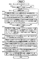
以下、これについて、図11の(A)乃至(F)を参照しながら、更に詳しく説明する。
【0013】
図11の(A)は、走査の良否とコードイメージ読み取りエラーとの関係を示したもので、手動走査に基づく不定の読取状態である、読取装置の傾き、浮き、回転、或いは走査時のスピード等によって走査状態が悪化すると、読み取りエラーが増加することを示している。図中の最悪走査は、ユーザが行う走査のうちほとんどのユーザがこの最悪の走査より良い走査の範囲で走査することを前提にして設定された走査である。このときの読取装置は、基準となる所定の読取装置であり、コードイメージは、基準となる所定の検査用のコードイメージである。
【0014】
図11の(B)は、読取装置の性能の良否とコードイメージ読み取りエラーとの関係を示したもので、コードイメージ読取装置の性能が悪化すると読み取りエラーが増加することを示している。図中の基準となる読取装置は、読取装置の種々の性能のうちユーザに対して供給し得る最悪の性能を持った読取装置である。このときの走査は、ユーザが行う走査のうちの所定の上記最悪の走査であり、コードイメージは、基準となる所定の検査用のコードイメージである。
【0015】
図11の(C)は、コードイメージの品質の良否とコードイメージ読み取りエラーとの関係を示したもので、コードイメージの品質が悪化すると読み取りエラーが増加することを示している。図中の基準となるコードイメージとは、コードイメージの種々の品質のうちユーザに対して供給し得る最悪の品質のコードイメージである。このときの読取装置は上記基準となる読取装置で、走査はユーザが行う走査のうち上記最悪の走査である。
【0016】
図11の(D)は、上記コードイメージの品質と、上記読取装置の性能と、上記手動走査の仕方の3つの要因で概ね決定されるコードイメージ読み取りエラーの量を示した概念図である。
【0017】
即ち、図中の立方体は、上記コードイメージの品質で決まる長さと、上記読取装置の性能で決まる長さと、上記手動走査の仕方で決まる長さの3辺より構成され、この立方体を一つの升とみなしたときに注入可能な水の容量が、実際の読み取り時に想定されるコードイメージ読み取りエラーの量に相当するものであることを示している。
【0018】
図11の(E)及び(F)は、手動走査を前提に、予め設定したエラー訂正の能力と、コードイメージ読み取りエラーとの関係を示した図である。ここで、予め設定されたエラー訂正の能力を図11の(E)ではコップAの容量として示してあり、また、図11の(F)ではコップBの容量として示してある。
【0019】
図11の(E)は、図11の(D)で示す升の水をコップAに注入した場合であって、コップAが、注入される水の量より大きな容量を持っているため、コップAから水が溢れ出ることはない。これは、予め設定されたエラー訂正能力が、最良走査に対する最悪走査時のコードイメージ読み取りエラーの増加分だけ、マージンを持っていることを意味している。これより殆どの場合、水が溢れ出ることはなく、換言すれば、エラー訂正処理後に残ったエラー数が「0」となり、読取装置はほぼ忠実に元のエラー訂正符号データを再生出力可能となる。
【0020】
従って、上記した特公昭63−33748号公報に開示の、エラー訂正処理した結果エラー訂正しきれなかったエラーの個数を表示するエラー状態表示装置が、本発明におけるコードイメージの品質検査に利用できないことは、既述の如く明らかである。
【0021】
また、図11の(F)は、図11の(D)で示す升の水をコップBに注入した場合であって、コップBが、注入される水の量より小さな容量であるため、コップBから水が溢れ出る。これは、予め設定されたエラー訂正能力が、最良走査に対する最悪走査時のコードイメージ読み取りエラーの増加分だけ、マージンを持っていないために起きる現象であって、当然に、元のエラー訂正符号データを忠実に再生出力することが困難となる。上記特公昭63−33748号公報に開示のエラー状態表示装置は、元々このようなコップBから溢れ出た水の量を測定する技術であって、同図のコップC内の水の量を測定することにより、読取装置や記録媒体の品質を検査するものと言える。
【0022】
以上の如く、コードイメージを読取装置で読み取った際の、コードイメージ読み取りエラーは、コードイメージの品質、読取装置の性能、及び手動による走査方法の3つの要因で概ね決まる。そして、そのうちの走査方法はユーザに依存するため製造側としては管理ができず、従って、ユーザが所定の自由度を持ちながら安定して走査するためには、コードイメージの品質と読取装置の性能について、確実に管理できるだけの検査方法が必要となる。
【0023】
ここでコードイメージ読み取りエラーとは、情報データを含むエラー訂正符号データをコードイメージとして印刷し、そのコードイメージを読取装置で光学的に読み取って処理を行う際、その読み取られたエラー訂正符号データと、本来正しく印刷記録されるべき元のエラー訂正符号データとの差異を指している。
【0024】
本発明は、上記した種々の事情に鑑みてなされたものであって、大規模で、高価な撮像部や画像解析部等を必要とすることなく、印刷工程中におけるコードイメージの抜き取り検査によって当該コードイメージの品質を簡便に検査することができ、また、エラー訂正処理によって訂正しきれなかったエラーが存在しなくとも、コードイメージの品質を確実に検査することが可能なコードイメージ品質検査装置を提供することを目的とするものである。
【0025】
【課題を解決するための手段】
上記の目的を達成するために、請求項1に記載の発明によるコードイメージ品質検査装置は、エラー訂正符号データが光学的に読み取り可能なコードイメージとして印刷記録された印刷媒体上の、該コードイメージの品質を検査するためのコードイメージ品質検査装置であって、
上記コードイメージを撮像する撮像手段と、
上記撮像手段で撮像されたコードイメージから上記エラー訂正符号データを復元する復元手段と、
上記復元手段で復元されたエラー訂正符号データについてエラー訂正処理を行う前の当該エラー訂正符号データから、上記撮像されたコードイメージの読み取りエラーを抽出する読み取りエラー抽出手段と、
上記読み取りエラー抽出手段で抽出された読み取りエラーを計数する計数手段と、
上記計数手段で計数された数値を所定の態様にて報知する報知手段と、
を具備し、
上記読み取りエラー抽出手段は、上記復元手段で復元されたエラー訂正符号データと、印刷記録されるべき理想的なコードイメージに対応するエラー訂正符号データとを比較して、その不一致部分を上記コードイメージ読み取りエラーとして抽出するように構成されたことを特徴とする。
【0026】
即ち、請求項1に記載の発明のコードイメージ品質検査装置によれば、計数手段にて計数された読み取りエラー数、又はその読み取りエラー数より算出されたエラーレートのうち何れかを報知手段で表示するようにしているので、被検査コードイメージの印刷品質を検査することが可能となる。これにより、印刷現場で手軽に、且つ、迅速に上記コードイメージの印刷品質を検査することができ、一方では、ユーザに対して走査自由度の高い、安定した走査感を与え得るコードイメージを提供することが可能となる。
【0027】
なおここで、コードイメージ読み取りエラーとは、後述する第1の実施の形態の説明においては、読み取って復元された音声情報,映像情報,及び各種ディジタルデータの少なくとも一つでなる情報データを含むエラー訂正符号データと、本来印刷記録されるべき元の理想的なドット配列情報との比較に基づく差分に対応し、第2の実施の形態の説明においては、復調データのエラー検出処理がなされた結果のエラーに対応する。
また、請求項2に記載の発明によるコードイメージ品質検査装置は、エラー訂正符号データが光学的に読み取り可能なコードイメージとして印刷記録された印刷媒体上の、該コードイメージの品質を検査するためのコードイメージ品質検査装置であって、
上記コードイメージを撮像する撮像手段と、
上記撮像手段で撮像されたコードイメージから上記エラー訂正符号データを復元する復元手段と、
上記復元手段で復元されたエラー訂正符号データについてエラー訂正処理を行う前の当該エラー訂正符号データから、上記撮像されたコードイメージの読み取りエラーを抽出する読み取りエラー抽出手段と、
上記読み取りエラー抽出手段で抽出された読み取りエラーを計数する計数手段と、
上記計数手段が計数した上記コードイメージ読み取りエラーの数値を各検査対象のコードイメージ間で規格化するための規格化手段と、
上記規格化手段で規格化された数値を所定の態様にて報知する報知手段と、
を具備することを特徴とする。
また、請求項3に記載の発明によるコードイメージ品質検査装置は、エラー訂正符号データが光学的に読み取り可能なコードイメージとして印刷記録された印刷媒体上の、該コードイメージの品質を検査するためのコードイメージ品質検査装置であって、
上記コードイメージを撮像する撮像手段と、
上記撮像手段で撮像されたコードイメージから上記エラー訂正符号データを復元する復元手段と、
上記復元手段で復元されたエラー訂正符号データについてエラー訂正処理を行う前の当該エラー訂正符号データから、上記撮像されたコードイメージの読み取りエラーを抽出する読み取りエラー抽出手段と、
上記読み取りエラー抽出手段で抽出された読み取りエラーを計数する計数手段と、
上記計数手段が計数した上記読み取りエラーの数値の、他の品質検査装置との性能差に基づく誤差を補正するための数値補正手段と、
上記数値補正手段で補正された数値を所定の態様にて報知する報知手段と、
を具備することを特徴とする。
また、請求項4に記載の発明によるコードイメージ品質検査装置は、エラー訂正符号データが光学的に読み取り可能なコードイメージとして印刷記録された印刷媒体上の、該コードイメージの品質を検査するためのコードイメージ品質検査装置であって、
上記コードイメージを撮像する撮像手段と、
上記撮像手段で撮像されたコードイメージから上記エラー訂正符号データを復元する復元手段と、
上記復元手段で復元されたエラー訂正符号データについてエラー訂正処理を行う前の当該エラー訂正符号データから、上記撮像されたコードイメージの読み取りエラーを抽出する読み取りエラー抽出手段と、
上記読み取りエラー抽出手段で抽出された読み取りエラーを計数する計数手段と、
上記計数手段で計数された数値を所定の態様にて報知する報知手段と、
を具備し、
上記コードイメージが、データを所定の情報量毎に分割したブロックデータの内容に応じてイメージ化されたデータパターンと、該ブロック毎に割り付けられたアドレスを表すアドレスデータの内容に応じてイメージ化されたアドレスデータパターンとから少なくとも構成されたブロックを、所定のブロック配列フォーマットに従って複数個配列したもの であるとき、
上記読み取りエラー抽出手段は、上記撮像手段で撮像されたコードイメージに含まれる上記各ブロックのアドレスと、印刷記録されるべき理想的なコードイメージに含まれる各ブロックのアドレスとを比較してその異なるアドレスを上記コードイメージ読み取りエラーとして抽出するように構成されたことを特徴とする。
また、請求項5に記載の発明によるコードイメージ品質検査装置は、エラー訂正符号データが光学的に読み取り可能なコードイメージとして印刷記録された印刷媒体上の、該コードイメージの品質を検査するためのコードイメージ品質検査装置であって、
上記コードイメージを撮像する撮像手段と、
上記撮像手段で撮像されたコードイメージから上記エラー訂正符号データを復元する復元手段と、
上記復元手段で復元されたエラー訂正符号データについてエラー訂正処理を行う前の当該エラー訂正符号データから、上記撮像されたコードイメージの読み取りエラーを抽出する読み取りエラー抽出手段と、
上記読み取りエラー抽出手段で抽出された読み取りエラーを計数する計数手段と、
上記計数手段で計数された数値を所定の態様にて報知する報知手段と、
を具備し、
上記読み取りエラー抽出手段は、上記読取手段が一のコードイメージ中の同一箇所を複数回撮像したときの当該同一箇所においてコードイメージ読み取りエラーが発生する確率を算出するエラー発生確率算出手段を更に含んでおり、
上記エラー発生確率算出手段で算出された値が所定の閾値を越えた上記箇所を上記コードイメージ読み取りエラーとして抽出するように構成されたことを特徴とする。
【0028】
また、請求項6に記載の発明によるコードイメージ品質検査装置は、エラー訂正符号データが光学的に読み取り可能なコードイメージとして印刷記録された印刷媒体上の、該コードイメージの品質を検査するためのコードイメージ品質検査装置であって、
上記コードイメージを撮像する撮像手段と、
上記撮像手段で撮像されたコードイメージから上記エラー訂正符号データを復元する復元手段と、
上記復元手段で復元されたエラー訂正符号データについてエラー訂正処理を行う前の当該エラー訂正符号データから、上記撮像されたコードイメージの読み取りエラーを抽出する読み取りエラー抽出手段と、
上記読み取りエラー抽出手段で抽出された読み取りエラーの、当該コードイメージ上での位置を検出する読み取りエラー位置検出手段と、
上記読み取りエラー位置検出手段で検出された位置を表示する表示手段と、
を具備し、
上記読み取りエラー抽出手段は、上記復元手段で復元されたエラー訂正符号データと、印刷記録されるべき理想的なコードイメージに対応するエラー訂正符号データとを比較して、その不一致部分を上記コードイメージ読み取りエラーとして抽出するように構成されたことを特徴とする。
【0029】
即ち、請求項6に記載の発明のコードイメージ品質検査装置によれば、読み取りエラー位置検出手段にて、読み取りエラー抽出手段で抽出されたコードイメージ読み取りエラーの、当該コードイメージ上での位置を検出して、これを表示手段に表示するようにしているので、読み取りエラー位置を検出することができ、品質不良箇所を特定でき、フィルムや刷版等の原版や印刷物のコードイメージ上の位置と対比して観察することにより、不具合箇所を容易に検出することができる。これによって、印刷工程へのフィードバックが可能となり、不良印刷物を極力少なくすることができる。
【0032】
【発明の実施の形態】
以下、本発明の実施の形態を図面を参照して説明する。
(第1の実施の形態)
図1の(A)は、本発明の第1の実施の形態に係るコードイメージ品質検査装置の構成を示したものである。
【0033】
本実施の形態では、コードイメージとして図10に示したドットコード10を用いており、このドットコードを手動で走査してドットコード全体を読み取り、そのドット単位の読み取りエラーを検出し、処理することで、ドットエラーレートを算出し、これをモニタに表示(報知)するようにしている。
【0034】
上記ドットのエラーレートは、被検査ドットコードの品質を表す指標の一つであって、これを管理することにより、ユーザには常に安定した品質のドットコードが供給でき、ドットコードを読取装置で走査した際には、再生出力が不可能となる等の不具合が解消される。
【0035】
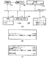
図1の(A)において、コードイメージ品質検査装置100は、CPUバス102に、撮像部104、撮像メモリ106、CPU108、RAM110、ROM112、マンマシンインターフェース114、及び出力部116が接続されて構成されている。
【0036】
また、同図中の実線はデータを、破線は制御信号を意味し、矢印の向きはデータや制御信号の向きを示す。制御信号は主たる信号のみを記載する。
撮像部104は、ドットコード10を照明し、そのドットコードからの反射光を撮像して読み取り、対応する画像データに変換する。撮像メモリ106は、この画像データを記憶する。CPU108は、プログラムにそって演算処理し、各構成及び全体の動作制御を司る。
【0037】
RAM110は、CPU108によって上記画像データを処理し出力部116に出力するまでの中間データ、例えば音声情報等の情報データを含むエラー訂正符号データを一時的に記憶し、また、制御情報等を記憶しておくためのものである。ROM112は、CPU108のプログラムを記憶し、且つ、各種パラメータ、テーブルデータ等を予め記憶しておくためのものである。
【0038】
マンマシンインターフェース114は、電源投入の指示やユーザの操作指示を入力するためのスイッチ部を具備する。出力部116は、復元されたエラー訂正符号データに基づく元の情報データである音声情報や映像情報を出力するためのスピーカやモニタ、そして、これを印字記録するためのプリンタ等を含む。
【0039】
以下、図2のフローチャートを参照して、このような構成のコードイメージ品質検査装置100のCPU108の動作を説明する。
先ず、マンマシンインターフェース114のスイッチ部にある電源スイッチをONにすると、当該コードイメージ品質検査装置100がイニシャライズされる(ステップS10)。このイニシャライズは、RAM110及び画像メモリ106のメモリチェックやクリア、撮像部104内に構成されてドットコードを読み取るための照明系LEDの消灯、撮像素子の動作チェック、出力部116の初期化として、表示部の画面クリアや音声出力を無音状態にするなど各種の設定を行う。
【0040】
次に、ユーザの読み取りの指示としてマンマシンインターフェース114の操作スイッチの押下状態であるかをチェックし(ステップS12)、押下状態であれば次に進み、押下状態でなければ該ステップS12を繰り返すことで待機する。
【0041】
次いで、撮像部104の撮像素子であるCCDと照明系のLEDを起動して画像取り込み状態にし、1画面分の画像取り込みを行う(ステップS14)。
そして、図10で示したドットコード10のマーカ18をこの取り込んだ1画面分の画像から検出し、この検出されたマーカの中心座標より図10のパターンコード16の存在を画像処理することでドットコード10の一部であるブロック12を認識し、更に、そのパターンコード16よりデータエリア14のドットを検出するための基準座標である読み取り基準点検出を行う(ステップS16)。
【0042】
次に、認識したブロックのブロックアドレス20を検出して、その検出されたブロックのブロックアドレスを検出し、取り込み済みブロックアドレスとしてRAM110にストアする(ステップS18)。
【0043】
その後、図10で示したデータエリア14内の所定のドット配列順に検出したドットの白か黒かを示すドット配列情報を、対応する「0」又は「1」の値として検出し、即ち情報データを含むエラー訂正符号データとして復元し、この復元された値に対応する各ドットの位置を示すドット位置情報と上記検出したブロックアドレスとからRAM110上のメモリアドレスを計算して、該メモリアドレスに上記ドット配列情報の値であるエラー訂正符号データをストアする(ステップS20)。
【0044】
そして、上記ステップS20で検出されたドット配列情報の値と、ROM112上の情報であって本来印刷記録されるべき元の理想的なドット配列情報の値とを比較して、不一致であるドットを検出し(コードイメージ読み取りエラーの抽出に相当)、その不一致数を計数する(ステップS22)。
【0045】
次に、操作スイッチが押下状態であるかをチェックし(ステップS24)、もし押下状態のままであれば上記ステップS14に戻り、次の画像を取り込んで、再度ステップS22までの処理を繰り返す。
【0046】
また、上記ステップS24で押下状態でないことを確認した場合には、RAM110に記憶した上記取り込み済みブロックアドレスより取り込みブロックアドレス総数を算出し、また、本来印刷記録されるべきドットコードのブロック総数をROM112上の上記元のドット配列情報から検出する(ステップS26)。ここで、ブロック総数とは、ドットコード中に記録された異なるブロックアドレスの総数を意味する。
【0047】
なお、本実施の形態におけるブロック総数は、上記ドットコードを記録する際の本来印刷記録されるべき元の理想的なドット配列情報から検出するようにしたが、ドット配列情報中にブロック総数を算出することができるパラメータ情報を予め記録しておき、実際に読み取ったドット配列情報から該パラメータ情報を抽出してブロック総数を算出することも可能である。
【0048】
次に、当該ドットコードの理想的なブロック総数と実際に取り込んだブロックアドレス総数を出力部で表示する(ステップS28)。なおここで、上記取り込みブロックアドレス総数と上記ドットコードの理想的なブロック総数との比を算出して、ブロックの読み取り率として表示するようにしても良い。
【0049】
上記取り込みブロックアドレスの総数と上記理想的ブロックの総数は、通常、一致するべきであり、上記読み取り率は100%となるべきであるが、この100%でないときは、当該品質検査装置100で被検査物のドットコードを走査したときのドットコードに品質不良があったか、或いは、そのときに走査ミスがあったかの何れかが原因として考えられる。従って、適正且つ良好な走査をしても上記割合が100%にならないときは、ドットコード自体に問題、即ち、品質不良のあったことがわかる。
【0050】
よって、上記取り込み済みブロックアドレスに基づいて、ドットコードの品質不良を検出することができ、更に、品質検査時の走査ミスも検出できる。
而して、上記ドットの不一致数と、上記理想的なブロックの総数から求められた総ドット数との比率を求めることによって、ドットコード品質検査の結果をドットコード間で規格化しており、ドット単位のエラーレートとしてこれを出力部で表示する(ステップS30)。そして、本フローを終了する。
【0051】
図1の(B)は、上記ステップS30での表示例を示す図で、求めた比率をドットエラーレートとして%表示を行っている。
このドットエラーレートは、読取装置での読み取り処理直後のドットに直接対応するエラー訂正符号データから求められた評価値であり、読み取り後の各種処理が無く、演算誤差も含まれない。従って、複数ドットのエラーが一つのエラーになったり複数のエラーに変化したりする復調処理等による精度劣化を生ずることがなく、印刷の品質を極めて精度良く判定することができる。また、エラーが多すぎてエラー訂正処理によって訂正しきれないときにでも確実にエラーレートを算出できる。
【0052】
また、この図1の(B)の表示例では、上記ステップS28で表示した上記取り込みブロックアドレス総数と理想的なブロック総数を、取り込みブロック総数とブロック総数として表示した。ここでは、取り込みブロック数=66、ブロック総数=68とした。これにより、取り込めなかったブロック数を意味するブロック落ち数を容易に確認することができる。このとき、ドットコードに対する走査が確実に行われているにも関わらず上記ブロック落ちが発生した場合には、ドットコードの品質に不具合のあることがほとんどであって、故に、ドットコードの品質の不具合が検出できる。このブロック落ち時のドットコードの品質不良部分としては、上記マーカ18の不良や、上記パターンコード16の不良、そして上記ブロックアドレス20の不良などが挙げられる。
【0053】
(第2の実施の形態)
次に、図3のフローチャートを参照して、第2の実施の形態に係るコードイメージ品質検査装置について説明する。
【0054】
本実施の形態の構成は、上記図1の(A)に示したコードイメージ品質検査装置の構成と同じであるので、その説明は省略する。また、図3のフローチャートにおけるステップS10乃至ステップS18の動作についても、既述の図2におけるフローチャートでの動作と同じであるので同様に省略する。
【0055】
即ち、上記ステップS10乃至ステップS18の処理を行った後、検出したブロックのブロックアドレスと、読み取って復元された値に対応する各ドットの位置情報とからRAM110上のメモリアドレスを計算し、ドット読み取り処理で復元されたドット配列情報としてのエラー訂正符号データを復調してから、RAM110上にマッピングしたインターリーブメモリ110Aの該メモリアドレスにストアする(ステップS40)。
【0056】
ここで、上記復調処理について説明する。図10におけるマーカ18とデータエリア14内のドットとをドットコードの読み取り処理時に確実に区別するためには、データエリア14内の黒ドットの連続数を制限する必要がある。そのため、情報データを含むエラー訂正符号データに対しては、印刷記録時に、例えば8−10変調処理が施してある。従って、ドット読み取り処理時にこの8−10変調された10ビットのエラー訂正符号データを8ビットのエラー訂正符号データに戻す必要があり、よって、10−8復調処理等の復調処理が必要となる。しかし、印刷記録の際の変調処理は必ずしも必要なものではない。また、印刷記録の際に、このような変調処理ではなく、別の処理を施して印刷記録することも考えられる。この場合、この別の処理を施して印刷記録されたコードイメージに対しては、読み取り処理時に、上記別の処理の逆変換に相当する処理を施す必要がある。
【0057】
図3のフローチャートに戻って、次に、マンマシンインターフェース114の操作スイッチが押下されたか否かをチェックし(ステップS24)、もし押下状態のままであれば上記ステップS14に戻って次の画像を取り込み、再度上記ステップS40までの処理を行う。
【0058】
また、上記ステップS24で操作スイッチが押下状態でないことを確認したときには、上記読み取って復調されたエラー訂正符号データを上記インターリーブメモリ110Aより読み出し、その復調データ中に含まれる検査パリティを利用してエラー検出処理を行い、エラー検出データ数を計数してエラー総数を算出し、これをコードイメージ読み取りエラー数とする。また、上記復調データ内に予め記録されているドットコードのデータ総数を当該復調データ内から検出する。そして、上記エラー総数とこのデータ総数の比から、データエラーレートを算出する(ステップS42)。
【0059】
ここで、上記エラー訂正符号データは、例えば、(88、72)リードソロモン符号の様に符号長を長く、且つ、パリティデータを多くすることで訂正能力を高く設定したものである。
【0060】
なお、図2のフローチャートでは、本来印刷記録されるべき元の理想的なドット配列情報がROM112上に前もって記憶されていたが、実際に印刷記録するドットコードは多種多様であり、上記元の理想的なドット配列情報もその分だけ複数個必要になって、更に、その複数のドット配列情報の選択も前もって必要となる。
【0061】
本第2の実施の形態においては、上記理想的なドット配列情報を品質検査装置のROM112上に持つことなく、実際の被検査ドットコード毎に読み取ったエラー訂正符号データからデータエラーレートを求めているため、検査対象としてのドットコードを限定することなく、全てのドットコードを印刷現場で速やかに検査することができる。
【0062】
上記のようにしてデータエラーレートが算出されたならば、次に、上記検出されたエラーとエラー訂正能力を踏まえて、全データ中のエラーを全て訂正可能であるか否かのエラー訂正可否判定を行う(ステップS44)。
【0063】
次いで、上記取り込み済みブロックアドレスより取り込みブロックアドレス総数を算出し、また、上記ドットコードのブロック総数を上記読み取ったエラー訂正符号データより検出する(ステップS46)。
【0064】
そして、上記ブロック総数と上記取り込みブロックアドレス総数とを出力部116で表示し(ステップS48)、上記算出したデータエラーレートを、出力部116で図1の(C)の表示例“データ(Byte)エラーレート”のように表示し(ステップS50)、上記エラー訂正可否判定の結果を図1の(C)の表示例“再生の可否”として出力部で表示する(ステップ52)。
【0065】
次に、上記データエラーレートに所定の補正係数を乗算することにより、基準機としてのコードイメージ品質検査装置で検査したときのエラーレート相当値に換算し、これを出力部で、図1の(C)の表示例“基準機エラーレート”のように表示して(ステップS54)、本フローチャートを終了する。
【0066】
上記補正係数は、基準とする所定のコードイメージ品質検査装置と、現コードイメージ品質検査装置100との性能差に基づいて予め決定された係数であって、この補正係数を現コードイメージ品質検査装置100で求められたエラーレートに乗じることで、現コードイメージ品質検査装置100と他のコードイメージ品質検査装置との間の性能差に基づく値の誤差が吸収でき、装置間での規格化が可能となる。
【0067】
以下に、この補正係数を求めるための方法について、図4の(A)及び(B)を参照しながら説明する。
先ず、基準とする品質検査装置、及び現品質検査装置100により、キャリブレーション用コードである所定のドットコードをそれぞれ読み取って、そのドットコードに対するデータエラーレートを検査する。ここで、基準品質検査装置のデータエラーレートをA、現品質検査装置のデータエラーレートをBとする。それにより、以下の式(1)で補正係数Kを算出する。
【0068】
補正係数K=A/B …(1)
また、実際の被検査ドットコードを現品質検査装置100で検査してデータエラーレートB’を算出し、以下の式(2)で補正データエラーレートを算出する。
【0069】
補正データエラーレートC=B’*K …(2)
図4の(A)で示すように、良好な印刷を行うと、殆ど全てのドットは同じ形状となり、エラーレートを極力低減することが可能となる。しかし、この良好に印刷され、エラーレートの低減されたドットコードに対して検査したときの、異なる複数の品質検査装置のエラーレート値は、各装置の性能バラツキが仮にあったとしてもほとんど同じエラーレートとなって、上記式(1)での補正係数K=1に近くなり、品質の良好でないドットコードに対して検査したときの検査装置の性能バラツキが効果的に補正できないものとなる。
【0070】
一方、ドット形状の悪化する印刷条件で印刷したドットコードは、通常、エラーが多く発生する傾向にある。性能バラツキのある、異なる複数の品質検査装置でこの様な不良なドットコードの品質検査を行うと、異なる複数の各品質検査装置間では、そのエラーレート値に大きな差が認められる。
【0071】
そこで、上記基準品質検査装置で読み取ったときのデータエラーレートが検査基準値相当となるドットコードをキャリブレーション用コードとして設定し、各品質検査装置では予めそのキャリブレーション用コードを測定し、上記式(1)により補正係数を求めておくことにより、基準品質検査装置との性能の違いのある複数の品質検査装置のエラーレート計測値を精度良く補正することが可能となる。
【0072】
また、上記検査基準のデータエラーレートをもった同一のドットコードを繰り返し複製することは難しいが、図4の(B)で示すようなドット形状の、イメージデータの異なる複数のドットパターンからなるドットコードであると、所定のデータエラーレートを示すドットコードを良好な印刷方式やイメージセッタによる印画紙出力によって、データエラーレートが大きく、しかも検査基準のデータエラーレートに近いドットコードを安定して複製できることが、本発明者による研究の結果、判明した。
【0073】
以上、データエラーレートの補正方法や補正係数算出用ドットコードについて説明したが、データエラーレートに限らずドットエラーレート等についても上記補正方法と補正係数算出用ドットコードを利用することができる。
【0074】
(第3の実施の形態)
次に、図5のフローチャートを参照して、第3の実施の形態に係るコードイメージ品質検査装置について説明する。
【0075】
本実施の形態の構成も、上記図1の(A)に示したコードイメージ品質検査装置の構成と同じであるので、その説明は省略する。また、図5のフローチャートにおけるステップS10乃至ステップS20の動作についても、既述の図2におけるフローチャートでの動作と同じであるので同様に省略する。
【0076】
即ち、上記ステップS10乃至ステップS20の処理を行った後、上記ステップS20で検出されたドット配列情報の値と、ROM112上の情報であって本来印刷記録されるべき元の理想的なドット配列情報の値とを比較して不一致であるドットを検出し、そのドットの各位置毎に不一致数を計数すると共に、そのときのドットに対する読み取り回数も計数する(ステップS60)。
【0077】
このS60の処理を詳しく説明すると、上記不一致数と上記読み取り回数をストアするメモリエリアをRAM101上に持ち、上記ステップS12での画像取り込みで取り込んだ前回までの画像で計数した上記2つの数を読み出し、今回検出した不一致数と読み取り回数を加算する処理である。なお、上記ステップS10のイニシャライズで上記2つの数は「0」に設定しておく。
【0078】
次に、マンマシンインターフェース114の操作スイッチの押下状態をチェックし(ステップS24)、もし押下状態のままであれば上記ステップS14に戻って次の画像を取り込み、再度上記ステップS60までの処理を行う。
【0079】
また、上記ステップS24で押下状態でないことを確認した場合には、次に、上記計数された不一致総数と上記読み取り回数の比率であるドット単位でのエラー発生確率を算出してこれを固定化率とし、その固定化率が所定の確率を越えるドット(コードイメージ読み取りエラーの抽出に相当)を計数し、その総数と全ドットの総数との比率より固定エラーレートを算出する。また、固定化率が所定の確率を越えるドットの、エラー訂正符号データとして格納されるRAM110上のメモリアドレスをエラードットアドレスとして検出し、これを別のメモリにストアしておく(ステップS62)。
【0080】
そして、上記ステップS62で処理された各種情報を図6の(A)の如く、出力部116にて表示し(ステップS64)、本フローチャートを終了する。
図6の(A)の例においては、上記固定エラーレートの%表示と取り込みブロック総数とコードのブロック総数とを表示し、また、設定した上記所定の確率も表示している。
【0081】
上記第1の実施の形態及び第2の実施の形態で説明したドットエラーレート及びデータエラーレートは、ドットコードと読取装置の双方に起因するエラーレートであったが、ここでの固定エラーレートはドットコードの品質に依存度の高い指標となる。これにより、ドットコードの品質を検査する上で、上記固定エラーレートは有効なものとなり、とりわけ、より厳格に品質検査の要求される印刷原版に対しては効果的となる。
【0082】
上記固定化率が所定の確率を越えるドットの位置の表示にあたっては、ドットコードの位置を示す座標等の数値で表示しても勿論良いが、同図に示す如く、ドットコードイメージの概略図を表示すると共に、該概略図中に不良を表す位置指標として、不良(劣化)1の位置指標118A、不良(劣化)2の位置指標118B等を表示することにより、より不良位置を分かりやすくして、検査者に即座にルーペ等で不良位置を確認し、不良の対策をさせることができる。
【0083】
なお、その不良の位置を拡大して、汚れやキズによる不良状況を図6の(B)乃至(E)に示す如く、同時又は時分割で表示することも可能である。
即ち、図6の(B)は、本来印刷記録されるべき元の理想的なドットの状態を拡大して示した図であり、図6の(C)及び図6の(D)は、汚れやキズによる不良状況をドットと併せて表示した図であり、更に図6の(E)は、読み取りエラーとして検出されたドットのみ黒いドットとして表示した図である。
【0084】
次に、上記図5のフローチャートにおけるステップS64の動作について、図7のサブルーチンを示すフローチャートに従って説明する。
先ず、上記求められた固定エラーレートを出力部116で表示する(ステップS64A)。
【0085】
そして、上記取り込みブロック総数とブロック総数を出力部で表示する(ステップS64B)。
更に、取り込み済みブロックアドレスとブロック総数から、取り込んでいないブロックアドレスを検出する(ステップS64C)。
【0086】
そして、上記別のメモリにストアされたエラードットアドレスに相当する上記RAM110のメモリアドレスから、図6の(A)で示すドットコード概略図において対応する位置を算出し、この算出された位置に基づいて、エラードットを黒ドットとして出力部に表示する(ステップS64D)。
【0087】
更に、上記取り込んでいないブロックアドレスに相当する位置のブロックは、ブロックアドレス未検出ブロックとして、取り込み済みブロックアドレスに相当するブロックとは異なった色で出力部に表示する。そして、取り込み済みブロックアドレスに相当する位置のブロックは、そのブロックアドレスに相当する数字を図6の(A)の如く表示させて(ステップS64E)、本フローチャートを終了する。
【0088】
ここで、図6の(A)中の不良1の位置指標118Aや不良2の位置指標118Bは、上記固定化率が所定の確率を越えるドットに対してのみドットコード概略図中で示すようにしてあり、加えて、その閾値としての所定の確率は、検査者が任意に設定して表示できるように構成されている。
【0089】
なお、本実施の形態では、抽出されたコードイメージ読み取りエラーの位置を表示するにあたって、ドットのエラーに基づいてこれを行っているが、上記第2の実施の形態において説明した如く、エラー検出処理された結果のデータエラーをコードイメージ読み取りエラーとして抽出し、これをその対応する位置に表示するようにしても勿論良い。
【0090】
多くの場合、印刷は印刷原版としてフィルム原版をつくり、次に該フィルム原版より写真と同様の光学的な焼き付け処理を行うことによって刷版を作製する。そのフィルム原版にキズやゴミ等の不良がある状態で刷版がつくられると、又は、刷版にキズやゴミの不良がある状態で印刷が行われると、その印刷で刷られる全ての印刷物に不良が生起される。ここで、その不良がドットコード上に存在すると、その不良のあるドットコード上の該当個所がコードイメージ読み取りエラーとなってしまう。故に、印刷原版フィルムや刷版については、極力、汚れやキズ等に対する注意を厳重に払っておく必要があると言える。既述の図5のフローチャートで説明した方法によれば、固定化率が高くエラーするドットのドットコード中での位置とその総数を検出しているため、この位置情報に基づいて、ルーペ等で視覚的に確認し、汚れを取るなどの対処をすることが簡単に行える。また、固定化率が高くエラーするドットとドットコード中のドット総数との比率より算出される固定エラーレートによって、印刷原版フィルムや刷版の不良度合いを検出することもでき、良好なドットコードの印刷を行うことが可能となる。更に、印刷原版フィルムや刷版の不良度を検出する以外に、印刷中に入るゴミ等によって固定化率が高くエラーするドットが発生することもあるが、その検査も兼ねることができる。
【0091】
(第4の実施の形態)
次に、本発明の第4の実施の形態として、上記したドットコードを元の音声情報等の知覚可能な情報として再生出力するためのコードイメージ読取装置について説明する。
【0092】
図4の(C)には、上記ドットコードを光学的に読み取って音声情報を再生出力するためのコードイメージ読取装置200のブロック構成図を示し、特に、該コードイメージ読取装置200のコードイメージ読み取りエラーに係る性能を検査するべく、読み取って復元した誤り訂正符号データ、又は、読み取ったコードイメージのデータを外部の検査機器に出力するためのインターフェース部が設けられている。
【0093】
また、図4の(D)には、そのコードイメージ読取装置200のインターフェース部より出力された情報を受けて、この読取装置の性能を検査し、その結果を表示する検査機器(エラーレート評価装置300)のブロック構成図が示されている。
【0094】
図4の(C)及び(D)の実線矢印及び破線矢印は、図1の(A)で説明した内容と同じであるため省略する。
図4の(C)において、コードイメージ読取装置200は、CPUバス202に、撮像部204、撮像メモリ206、CPU208、RAM210、ROM212、スイッチ部214、出力部216、及びインターフェース部218を接続して構成されている。
【0095】
ここで、撮像部204は、ドットコードを照明し、そのドットコードからの反射光を撮像して読み取り、対応する画像データに変換する。撮像メモリ206は、この画像データを記憶する。CPU208は、プログラムにそって演算処理し、各構成及び全体の動作制御を司る。
【0096】
RAM210は、このCPU208によって上記画像データを処理し、出力部216に出力するまでの中間データ、例えば音声情報等の情報データを含むエラー訂正符号データを一時的に記憶し、また、制御情報等を記憶するためのものである。また、ROM212は、CPU208のプログラムを記憶し、且つ、各種パラメータ、テーブルデータ等を予め記憶しておくためのものである。
【0097】
スイッチ部214は、電源の投入の指示や操作者の操作指示を入力するためのものである。出力部216は、復元されたエラー訂正符号データに基づく元の情報データである音声情報や映像情報を出力するためのスピーカやモニタ、そして、これを印字記録するためのプリンタ等を含む。インターフェース部218は、外部のパーソナルコンピュータ等とデータの転送を可能とするためのものである。
【0098】
また、図4の(D)において、エラーレート評価装置300は、CPUバス302に、CPU304、RAM306、ROM308、インターフェース部310、及び出力部312を接続して構成されている。
【0099】
ここで、CPU304は、各構成及び全体の動作制御を司る。RAM306は、出力部312に出力するまでの中間データ、例えば音声情報等の情報データを含むエラー訂正符号データを一時的に記憶し、また、制御情報等を記憶するためのものであり、ROM308は、CPU304のプログラムを記憶し、且つ、各種パラメータ、テーブルデータ等を予め記憶しておくためのものである。インターフェース部310は、図4の(C)に示すような外部のドットコード読取装置200とデータの転送を行うためのものであり、出力部312は、転送されたデータを処理した後性能検査結果をモニタに表示したり、音声で出力したり、プリンタで印字記録したりするものである。
【0100】
以下、図8のフローチャートを参照して、上記図4の(C)で示したコードイメージ読取装置200に係るエラーレート計測時の動作を説明する。
本フローチャートにおいて、ステップS70乃至ステップS82の各ステップは、図3で示したフローチャートにおけるステップS10乃至ステップS18、ステップS40、及びステップS24と続く一連の処理ステップと同じものであるため、その説明を省略する。
【0101】
但し、ここでは、図3のフローチャートとは異なり、検査基準たる所定の検査用基準コードイメージに対する読取装置の読み取り性能とその読み取り装置毎の性能バラツキを測定して、この読取装置自体を検査することを目的としたものであって、従って、ここでの検査対象とするコードイメージは、所定の限られた範囲の印刷品質を有したコードイメージとすべきであり、好ましくは一つのコードイメージによって検査されるべきである。
【0102】
この所定の検査用基準コードイメージを用いることにより、各製造された読取装置200の読み取り性能を検査することが可能となる。
図8のフローチャートに戻って、ステップS82において操作スイッチが押下状態でないことを確認した場合には、復調されたデータのエラー訂正処理、音声伸長処理、音声再生出力処理等を行う(ステップS84)。なお、このステップS84での処理は、読取装置200の性能検査に直接関係が無いため、適宜省略することが可能である。
【0103】
次に、コードイメージ読取装置200のインターフェース部218を介して接続された不図示パーソナルコンピュータ(PC)に、データ取り込み終了情報を転送し(ステップS86)、パーソナルコンピュータが受信可能であれば、上記復調されたデータの全部と取り込み済みブロックアドレスをパーソナルコンピュータに転送する(ステップS88)。そして、本処理を終了する。
【0104】
ここで、上記ステップS86及びステップS88におけるパーソナルコンピュータとのデータ転送については、図4の(C)に示す読取装置200がホスト側となって転送を指示するようにしたが、必ずしも読取装置200がホスト側である必要はなく、各種のインターフェース方式が可能となる。このインターフェース方式としては、パラレル方式のSCSI、シリアル方式のRS232C、読取装置側のメモリ(RAM)をパーソナルコンピュータのスロットに装着されたメモリカードにおけるメモリ部分とみなしてこれを認識させる方法、或いは光転送方式のIRDA、更に磁気転送方式等が挙げられ、種々の方式が採用し得るものである。
【0105】
次に、図4の(D)に示した、パーソナルコンピュータを利用して構成された検査機器である読取装置性能表示装置即ちエラーレート評価装置300の動作について説明するが、ここでは、上記図8のフローチャートにおける上記ステップS88での、全復調データを処理して検査結果を表示する動作について、図9のフローチャートを参照しながら詳細に説明する。
【0106】
先ず、図示しないスイッチ部にある電源スイッチをONにすると、イニシャライズされる(ステップS90)。このイニシャライズでは、RAM306のメモリチェックやクリア、出力部312の初期化である表示部の画面クリア、そして外部とのインターフェース部310の初期設定等を行う。
【0107】
次に、図8のステップS86で転送されるデータ取り込み終了情報をインターフェース部310で受ける(ステップS92)。これは、検査するための全復調データが揃ったことを意味する。
【0108】
このデータ取り込み終了情報を受信したならば、図8のステップS88で転送する全復調データと取り込み済みブロックアドレスを受信する(ステップS94)。
【0109】
そして、この復調データのエラー検出処理を行い、エラー検出データ数を計数してエラー総数を求めると共に、上記復調データ内に記録されている情報から総データ数を求め、上記エラー総数と上記総データ数の比からデータエラーレートを算出する(ステップS96)。
【0110】
なお、ステップS98以降の各ステップは、図3のフローチャートにおけるステップS42以降の各ステップと同じ内容であるため、その説明を省略する。
ここで、図9に示した例では、データエラーレートを抽出することによって当該読取装置の性能を検査するようにしたが、必ずしもデータエラーレートを用いる必要は無く、例えば、第1の実施の形態で説明したドットエラーレートや、或いは第3の実施の形態で説明した固定エラーレートを用いるようにしても良い。その場合、図8のステップS88、又は、図9のステップS94で転送するデータは、復調された全データと取り込み済みブロックアドレスであったが、これを図2及び図5で説明した如く、検出したドット配列情報と取り込み済みブロックアドレスに変更すれば良い。
【0111】
また、上記転送するデータをステップS74で取り込んだ画像データとし、その画像データに対する処理である図8のステップS74乃至ステップS84の処理と、図9のステップS92以降の処理を図4の(D)のエラーレート評価装置300側で全て行うようにしても良い。
【0112】
以上、本実施の形態によれば、読み取り性能を検査可能な読取装置と読取装置性能検査機器とにより、当該読取装置の読み取り性能、とりわけ、読取装置の組立性能や照明バラツキ、レンズバラツキ、CCDバラツキ等を簡便に検査し管理することができ、常に安定した読み取り性能を有するコードイメージ読取装置が提供できる。
【0113】
なお、以上は読取装置のオーバーオールの性能検査として、各種エラーレートを算出して検査する方法を説明したが、読取装置の部分的な各機能の品質検査を行うことにより、全体の性能を維持管理することが可能となる。そこで、図4の(C)及び図4の(D)と同じ構成で、上記読取装置の部分的な各機能の品質検査を行うことができる。
【0114】
その方法を、以下に説明する。
先ず、上記した転送データをステップS74での取り込んだ画像データとし、図4の(D)に示す検査機器(エラーレート評価装置300)で各種の処理を行う。
【0115】
このときの図4の(C)の撮像部204は、照明及びその制御機構を含む照明系と、レンズ等から成る光学系と、撮像素子とそのドライブ回路からなる撮像回路とで構成されている。従って、照明系によるコードイメージ上の配光特性と光学系と撮像回路による画面上の輝度ムラや全体光量などを検査することができ、上記撮像部内部の各機能の検査が行える。また、コードイメージの代わりに、専用のテストチャートを撮像することにより、レンズ等のMTF(Modulation Transform Function)特性も併せて検査することができる。
【0116】
以上各実施の形態に基づいて本発明を説明したが、本発明は上述した実施の形態に限定されるものではなく、本発明の要旨の範囲内で種々の変形や応用が可能である。ここで、本発明の要旨をまとめると以下のようになる。
【0117】
(1) 音声情報,映像情報,及び各種ディジタルデータの少なくとも一つでなる情報データを含むエラー訂正符号データが手動走査による光学的に読み取り可能なコードイメージとして印刷記録された印刷媒体上の、該コードイメージの品質を検査するためのコードイメージ品質検査装置であって、
上記エラー訂正符号データは、少なくともコードイメージの品質、コードイメージ読取装置の性能、及び該読取装置の手動走査に基づく不定の読取状態に各起因したコードイメージ読み取りエラーに対応し得るエラー訂正能力を予め備えており、
上記コードイメージ品質検査装置は、
上記コードイメージを撮像して光学的に読み取る読取手段と、
上記読取手段で読み取られたコードイメージをエラー訂正符号データに復元する復元手段と、
上記復元手段で復元されたエラー訂正符号データについて、エラー訂正処理を実行せずに、上記コードイメージ読み取りエラーを抽出する読み取りエラー抽出手段と、
上記読み取りエラー抽出手段で抽出された読み取りエラーを所定の単位に数値化して計数する計数手段と、
上記計数手段で計数された数値を所定の態様にて報知する報知手段と、
を具備することを特徴とするコードイメージ品質検査装置。
【0118】
即ち、大規模で、高価な撮像部や画像解析部等を必要とすることなく、印刷工程中におけるコードイメージの抜き取り検査によって当該コードイメージの品質を簡便に検査することができ、また、エラー訂正処理によって訂正しきれなかったエラーが存在しなくとも、コードイメージの品質を確実に検査することが可能なコードイメージ品質検査装置、及び、この種コードイメージを読み取るための読取装置における読み取り性能を外部より容易に検査可能となしたコードイメージ読取装置を提供することができる。
【0119】
(2) 上記読み取りエラー抽出手段は、上記復元手段で復元されたエラー訂正符号データと、印刷記録されるべきコードイメージに対応するエラー訂正符号データとを比較して、その異なる部分を上記コードイメージ読み取りエラーとして抽出するものであることを特徴とする上記(1)に記載のコードイメージ品質検査装置。
【0120】
即ち、上記(1)の効果に加えて、コードイメージの検査がダイレクトに行え、且つ、比較という単純な処理のため、検査精度が高く処理が簡単な品質検査装置が提供できる。
【0121】
(3) 上記読み取りエラー抽出手段は、上記復元手段で復元されたエラー訂正符号データのエラー検出によるエラーを上記コードイメージ読み取りエラーとして抽出するものであることを特徴とする上記(1)に記載のコードイメージ品質検査装置。
【0122】
即ち、上記(1)の効果に加えて、互いにエラー訂正符号の違う複数の被検査コードイメージを、比較する理想的なデータやその選択する処理を行うこと無しに、手軽に検査をすることができる。
【0123】
(4) 上記コードイメージは、エラー訂正符号データ中の各「1」又は「0」の値に対応した所定の反射率又は色を有するドットイメージが2次元に複数個配列されたドットパターンを含むものであることを特徴とする上記(2)及び(3)の何れか一に記載のコードイメージ品質検査装置。
【0124】
即ち、上記(2)又は(3)の効果に加えて、コードイメージであるドットコード読み取り単位の最小単位で比較するため、印刷の状態を確実にとらえることができ、より精度の高い測定をすることができる。
【0125】
(5) 上記コードイメージ品質検査装置は、上記計数手段が計数した上記コードイメージ読み取りエラーの数値を各検査対象のコードイメージ間で規格化するための規格化手段を更に具備することを特徴とする上記(1)に記載のコードイメージ品質検査装置。
【0126】
即ち、上記(1)の効果に加えて、音声等の情報データの情報量の違うコードイメージが同一の印刷品質下で印刷された場合、そのコードイメージの情報量に応じて読み取りエラー数が変化してしまうが、上記各検査対象のコードイメージ間で規格化(ノーマライズ)を行うことにより、印刷品質を素早く、且つ、的確に判断することができる。
【0127】
(6) 上記コードイメージ品質検査装置は、上記計数手段が計数した上記コードイメージ読み取りエラーの数値の、他の品質検査装置との性能差に基づく誤差を補正するための数値補正手段を更に具備することを特徴とする上記(1)に記載のコードイメージ品質検査装置。
【0128】
即ち、上記(1)の効果に加えて、基準となる品質検査装置に対して他の品質検査装置を使用して検査しても、的確に検査をすることができる。従って、品質検査装置の違いによる基準ズレを極力少なくすることができ、また、判定ミスを少なくすることができる。
【0129】
(7) 上記コードイメージが、上記エラー訂正符号データを所定の情報量毎に分割したブロックデータの内容に応じてイメージ化されたデータパターンと、該ブロック毎に割り付けられたアドレスを表すアドレスデータの内容に応じてイメージ化されたアドレスデータパターンとから少なくとも構成されたブロックを、所定のブロック配列フォーマットに従って複数個配列したものであって、
上記読み取りエラー抽出手段は、上記読取手段で読み取ったコードイメージに含まれる上記各ブロックのアドレスと、印刷記録されるべきコードイメージに含まれる各ブロックのアドレスとを比較してその異なるアドレスを上記コードイメージ読み取りエラーとして抽出するものであることを特徴とする上記(1)に記載のコードイメージ品質検査装置。
【0130】
即ち、上記(1)の効果に加えて、エラー訂正符号データに基づいてコードイメージ読み取りエラーの抽出を行う構成のものに比べ、読み取り処理におけるより大きな読取障害となるブロックアドレス認識不能状態を読み取りエラーの抽出として物理フォーマット構成を巧みに利用して行えるため、印刷品質の検査がより簡単、且つ、素早く行える。
【0131】
(8) 上記読み取りエラー抽出手段は、上記読取手段が一のコードイメージ中の同一箇所を複数回読み取ったときの当該同一箇所においてコードイメージ読み取りエラーが発生する確率を算出するエラー発生確率算出手段を更に含んでおり、
上記エラー発生確率算出手段で算出された値が所定の閾値を越えた上記箇所を上記コードイメージ読み取りエラーとして抽出するものであることを特徴とする上記(1)に記載のコードイメージ品質検査装置。
【0132】
即ち、上記(1)の効果に加えて、1回の走査、又は複数回にわたる走査において、何回も読み取りエラーするコードイメージ中の箇所を検出でき、その頻度を検査することができる。これにより、読み取りエラーの確率の高い箇所を検出して、その読み取りエラー確率の高い箇所の集中している場所やその頻度を知ることができるため、コードイメージの品質をより精度良く検査できる。そして、上記読み取りエラー発生確率の高い箇所に存在するであろう、大きなゴミやインキの塊、それにキズ等を探すことが容易にでき、印刷物に限らず、印刷原版であるフィルムについても本装置を適用することで、多くの不良印刷物が印刷されることを低減できる。
【0133】
(9) 音声情報,映像情報,及び各種ディジタルデータの少なくとも一つでなる情報データを含むエラー訂正符号データが手動走査による光学的に読み取り可能なコードイメージとして印刷記録された印刷媒体上の、該コードイメージの品質を検査するためのコードイメージ品質検査装置であって、
上記エラー訂正符号データは、少なくともコードイメージの品質、コードイメージ読取装置の性能、及び該読取装置の手動走査に基づく不定の読取状態に各起因したコードイメージ読み取りエラーに対応し得るエラー訂正能力を予め備えており、
上記コードイメージ品質検査装置は、
上記コードイメージを撮像して光学的に読み取る読取手段と、
上記読取手段で読み取られたコードイメージをエラー訂正符号データに復元する復元手段と、
上記復元手段で復元されたエラー訂正符号データについて、エラー訂正処理を実行せずに、上記コードイメージ読み取りエラーを抽出する読み取りエラー抽出手段と、
上記読み取りエラー抽出手段で抽出されたコードイメージ読み取りエラーの、当該コードイメージ上での位置を検出する読み取りエラー位置検出手段と、
上記読み取りエラー位置検出手段で検出された位置を表示する表示手段と、を具備することを特徴とするコードイメージ品質検査装置。
【0134】
即ち、読み取りエラー位置を検出することができ、品質不良箇所を特定でき、フィルムや刷版等の原版や印刷物のコードイメージ上の位置と対比して観察することにより、不具合箇所を容易に検出することができる。これによって、印刷工程へのフィードバックが可能となり、不良印刷物を極力少なくすることができる。
【0135】
(10) 上記読み取りエラー抽出手段は、上記復元手段で復元されたエラー訂正符号データと、印刷記録されるべきコードイメージに対応するエラー訂正符号データとを比較して、その異なる部分を上記コードイメージ読み取りエラーとして抽出するものであることを特徴とする上記(9)に記載のコードイメージ品質検査装置。
【0136】
即ち、上記(9)の効果に加えて、コードイメージの検査がダイレクトに行え、且つ、比較という単純な処理のため、検査精度が高く、処理が簡単な装置が提供できる。
【0137】
(11) 上記読み取りエラー抽出手段は、上記復元手段で復元されたエラー訂正符号データのエラー検出によるエラーを上記コードイメージ読み取りエラーとして抽出するものであることを特徴とする上記(9)に記載のコードイメージ品質検査装置。
【0138】
即ち、上記(9)の効果に加えて、互いにエラー訂正符号の違う複数の被検査コードイメージを、比較する理想的なデータやその選択する処理を行うこと無しに、手軽に検査をすることができる。
【0139】
(12) 上記コードイメージは、エラー訂正符号データ中の各「1」又は「0」の値に対応した所定の反射率又は色を有するドットイメージが2次元に複数個配列されたドットパターンを含むものであることを特徴とする上記(10)及び(11)の何れか一に記載のコードイメージ品質検査装置。
【0140】
即ち、上記(10)又は(11)何れかの効果に加えて、コードイメージであるドットコード読み取り単位の最小単位で比較するため、印刷の状態を確実にとらえることができ、より精度の高い測定をすることができる。
【0141】
(13) 上記コードイメージが、上記エラー訂正符号データを所定の情報量毎に分割したブロックデータの内容に応じてイメージ化されたデータパターンと、該ブロック毎に割り付けられたアドレスを表すアドレスデータの内容に応じてイメージ化されたアドレスデータパターンとから少なくとも構成されたブロックを、所定のブロック配列フォーマットに従って複数個配列したものであって、
上記読み取りエラー抽出手段は、上記読取手段で読み取ったコードイメージに含まれる上記各ブロックのアドレスと、印刷記録されるべきコードイメージに含まれる各ブロックのアドレスとを比較してその異なるアドレスを上記コードイメージ読み取りエラーとして抽出するものであることを特徴とする上記(9)に記載のコードイメージ品質検査装置。
【0142】
即ち、上記(9)の効果に加えて、エラー訂正符号データに基づいてコードイメージ読み取りエラーの抽出を行う構成のものに比べ、読み取り処理におけるより大きな読取障害となるブロックアドレス認識不能状態を読み取りエラーの抽出として物理フォーマット構成を巧みに利用して行えるため、印刷品質の検査がより簡単、且つ、素早く行える。そして、そのときのブロック検出できなかったコードイメージ中の不良位置をブロック単位で見易く表示することで品質不良箇所を簡単に見つけることができる。
【0143】
(14) 音声情報,映像情報,及び各種ディジタルデータの少なくとも一つでなる情報データを含むエラー訂正符号データが手動走査による光学的に読み取り可能なコードイメージとして印刷記録された印刷媒体から、該コードイメージを撮像して光学的に読み取る読取手段と、
上記読取手段で読み取られたコードイメージをエラー訂正符号データに復元する復元手段と、
上記復元手段で復元されたエラー訂正符号データのエラー訂正処理を行うエラー訂正処理手段と、
上記エラー訂正処理手段でエラー訂正処理されたデータを元の情報データとして外部に出力する出力手段と、
を具備するコードイメージ読取装置であって、
上記エラー訂正符号データは、少なくともコードイメージの品質、当該読取装置の性能、及び当該読取装置の手動走査に基づく不定の読取状態に各起因したコードイメージ読み取りエラーに対応し得るエラー訂正能力を予め備えており、
当該読取装置のコードイメージ読み取りエラーに係る性能を検査するべく、上記読取手段が読み取って上記復元手段が復元したエラー訂正符号データ、又は、上記読取手段が読み取ったコードイメージのデータを外部の検査機器に出力するためのインターフェース手段を更に具備することを特徴とするコードイメージ読取装置。
【0144】
即ち、コードイメージ読取装置の性能や複数のコードイメージ読取装置毎のバラツキを検査することができ、常に安定したコードイメージ読取装置をユーザに提供することができる。
【0145】
(15) 上記読取装置の上記読み取りエラーに係る性能を検査するべく、上記インターフェース手段が出力する上記復元手段が復元したエラー訂正符号データ、又は、上記読取手段が読み取ったコードイメージのデータは、所定の検査用基準コードイメージに基づいたデータであることを特徴とする上記(14)に記載のコードイメージ読取装置。
【0146】
即ち、上記(14)の効果に加えて、コードイメージ読取装置の性能検査を所定の検査用基準コードイメージに基づいて行っているため、常により安定した読取性能のコードイメージ読取装置をユーザに提供することができる。
【0147】
【発明の効果】
以上詳述したように、本発明によれば、大規模で、高価な撮像部や画像解析部等を必要とすることなく、印刷工程中におけるコードイメージの抜き取り検査によって当該コードイメージの品質を簡便に検査することができ、また、エラー訂正処理によって訂正しきれなかったエラーが存在しなくとも、コードイメージの品質を確実に検査することが可能なコードイメージ品質検査装置を提供することができる。
【図面の簡単な説明】
【図1】(A)は本発明の第1の実施の形態に係るコードイメージ品質検査装置のブロック構成図であり、(B)及び(C)はそれぞれ第1及び第2の実施の形態に係るコードイメージ品質検査装置の表示例を示す図である。
【図2】第1の実施の形態に係るコードイメージ品質検査装置の予めROMに記録されている情報と読み取った情報を比較しドット単位のエラーレートを算出する動作のフローチャートである。
【図3】本発明の第2の実施の形態に係るコードイメージ品質検査装置のエラー訂正符号を使ってデータエラーレートを算出する動作のフローチャートである。
【図4】(A)及び(B)は補正係数を求めるための方法を説明するための図で、特に(A)はドット形状が全て同じコードを示し、(B)はドット形状が違うドットからなるコードを示しており、(C)は本発明の第4の実施の形態に係るコードイメージ読取装置のブロック構成図であり、(D)は(C)のコードイメージ読取装置の性能を検査しその結果を表示するエラーレート評価装置のブロック構成図である。
【図5】本発明の第3の実施の形態に係るコードイメージ品質検査装置の高確率に読み誤るドットの全体比率である固定エラーレートを算出する動作のフローチャートである。
【図6】(A)は第3の実施の形態に係るコードイメージ品質検査装置の印刷原版の不良についての表示例を示す図、(B)は本来印刷記録されるべき元の理想的なドットの状態を拡大して示した図、(C)及び(D)はそれぞれ汚れやキズによる不良状況をドットと併せて表示した図であり、(E)は読み取りエラーとして検出されたドットのみ黒いドットとして表示した図である。
【図7】図5のフローチャートにおけるステップS64のサブルーチンを示すフローチャートである。
【図8】第4の実施の形態に係るコードイメージ読取装置のエラーレート計測時の動作フローチャートである。
【図9】第4の実施の形態におけるエラーレート評価装置の動作フローチャートである。
【図10】ドットコードの物理フォーマット構成を示す図である。
【図11】(A)は走査の良否とコードイメージ読み取りエラーとの関係を示す図、(B)は読取装置の性能の良否とコードイメージ読み取りエラーとの関係を示す図、(C)はコードイメージの品質の良否とコードイメージ読み取りエラーとの関係を示す図、(D)はコードイメージの品質と読取装置の性能と手動走査の仕方の3つの要因で概ね決定されるコードイメージ読み取りエラーの量を示した概念図であり、(E)及び(F)はそれぞれ手動走査を前提に予め設定したエラー訂正の能力とコードイメージ読み取りエラーとの関係を示した図である。
【符号の説明】
10 ドットコード
12 ブロック
14 データエリア
16 パターンコード
18 マーカ
20 エラー検出又はエラー訂正符号を含むブロックアドレス
100 コードイメージ品質検査装置
102,202,302 CPUバス
104,204 撮像部
106,206 撮像メモリ
108,208,304 CPU
110,210,306 RAM
110A,210A インターリーブメモリ
112,212,308 ROM
114 マンマシンインターフェース
116,216,312 出力部
200 コードイメージ読取装置
214 スイッチ部
218,310 インターフェース部
300 エラーレート評価装置[0001]
BACKGROUND OF THE INVENTION
The present invention is for inspecting the quality of a code image on a print medium on which information data including at least one of audio information, video information, or various digital data is printed and recorded as an optically readable code image. Code image quality inspectionEquipmentIt is related.
[0002]
[Prior art]
The present applicant manually scans the dot code, which is a code image for printing and recording information data such as audio information on a print medium such as paper, in an optically readable form, and the dot code manually. A reading device that optically reads and reproduces and outputs the original audio information and the like has been invented and proposed in Japanese Patent Laid-Open No. 6-231466.
[0003]
FIG. 10 shows the physical format configuration of the
That is, a plurality of
[0004]
Since this
Thus, the dot code consisting of such a physical format has various printing methods with different methods and models, various printing materials with different paper and ink, and various management methods with different adjustments and settings of the printing press. Printing is performed under various printing conditions determined by a combination of the above. Accordingly, in order to always read the dot code stably with a predetermined reading device under any conditions, it is necessary to always maintain the print quality of the dot code itself stably. Therefore, quality inspection for the dot code is required for that purpose.
[0005]
Conventionally known bar codes measure the density of bars, the width of bars, the distance between bars, etc., and check the quality of printing. For example, as disclosed in Japanese Patent Laid-Open No. 5-77530, this barcode inspection apparatus is automatically attached to a printing press or printer.
[0006]
In addition, although it is preferable to inspect all the printed materials, a sampling inspection method is also known in which all printed materials are controlled to a predetermined quality by inspecting the quality of some printed materials extracted from the printed materials. . This is superior in that the total cost including the inspection can be reduced as compared with the case where all inspections are performed.
[0007]
This sampling inspection method is frequently used in the quality inspection of the photographic image quality of a printed matter including photographs, which is performed in normal printing.
To explain this, a sheet-fed printing press using the offset printing method normally prints at a speed of 10,000 sheets per hour. The quality inspection of the photographic part in the printed material is performed by extracting the printing paper during the printing process and observing a part of the plurality of photographs in the extracted paper or dispersing in the extracted paper. The quality of the photograph is managed by measuring a predetermined pattern arranged in this way with a densitometer. In other words, it is considered that the total number is managed by extracting a predetermined printing sheet from all printed matter and inspecting a part of the extracted sheet. This is possible because normal printing is based on the premise that the quality of a photograph of a printed matter hardly changes with a difference of several sheets.
[0008]
Therefore, it is conceivable to apply the above-described barcode inspection method to the above-described dot code and further apply the above-described sampling inspection method. In other words, the quality of all dot codes of all printed materials is checked by measuring the characteristic amount (density, size, distance between dots, etc.) of dots and markers of one dot code present in the extracted paper. It is.
[0009]
However, in order to perform the same thing as the above-mentioned Japanese Patent Application Laid-Open No. 5-77530 for the dot code, an image analyzing unit and an image analyzing unit that analyzes the shape and density of dots and the like from image data from the image capturing unit are provided. Necessary. As this imaging unit, a resolution capable of analyzing the shape of the dots and capable of imaging the entire size of one code is required. Therefore, the apparatus becomes large and expensive. In addition, since the dot code is composed of an extremely large number of dots and markers, it takes too much processing time to measure the size, shape, and density using a normal image analysis device, which can be used for quality inspection of dot codes. It is practically difficult to apply.
[0010]
As another dot code quality inspection method, since the information data to be printed and recorded is configured as error correction code data, the digital information signal error status display device disclosed in Japanese Patent Publication No. 63-33748 is used. It is also possible to do. In this case, the large-scale imaging device as described above is not necessarily required, and an increase in device cost can be suppressed, but it is extremely difficult to inspect the quality of the dot code for another reason.
[0011]
That is, the error correction capability of error correction code data including information data to be printed and recorded as a dot code is at least the quality of the dot code, the performance of the reading device, and the indefinite reading state based on manual scanning of the reading device. It is indispensable to have an error correction capability that can cope with the dot code reading error caused by each of the error codes. After the error correction processing when the data is read under the condition, the error correction code data surely has an error correction capability of a level in which almost no error remains. Therefore, when the error status display device that displays the number of errors that cannot be corrected as a result of the error correction processing disclosed in the above Japanese Patent Publication No. 63-33748 is used for quality inspection of the dot code, Since the error number cannot be displayed in the first place, it cannot be suitably used for the quality inspection apparatus for the dot code. Note that the print recording in the present invention includes not only normal offset printing and letterpress printing, but also printing printing by various recording printers such as thermal transfer and ink jet printing.
[0012]
[Problems to be solved by the invention]
As described above, the code image premised on reading by manual scanning needs to have a strong error correction capability set in advance.
Hereinafter, this will be described in more detail with reference to (A) to (F) of FIG.
[0013]
FIG. 11A shows the relationship between scanning quality and code image reading error. The reading device tilt, float, rotation, or scanning speed is an indefinite reading state based on manual scanning. If the scanning state deteriorates due to, for example, the reading error increases. The worst scan in the figure is a scan set on the assumption that most of the scans performed by the user scan within a scan range better than the worst scan. The reading device at this time is a predetermined reading device serving as a reference, and the code image is a predetermined code image for inspection used as a reference.
[0014]
FIG. 11B shows the relationship between the quality of the reading device and the code image reading error, and shows that the reading error increases when the performance of the code image reading device deteriorates. The reference reading device in the figure is a reading device having the worst performance that can be supplied to the user among various performances of the reading device. The scan at this time is the predetermined worst scan among the scans performed by the user, and the code image is a code image for a predetermined test as a reference.
[0015]
FIG. 11C shows the relationship between the quality of the code image and the code image reading error, and indicates that the reading error increases when the quality of the code image deteriorates. The reference code image in the figure is the worst quality code image that can be supplied to the user among various qualities of the code image. The reading device at this time is the reference reading device, and the scanning is the worst scanning among the scanning performed by the user.
[0016]
FIG. 11D is a conceptual diagram showing the amount of code image reading error that is roughly determined by three factors: the quality of the code image, the performance of the reading device, and the manual scanning method.
[0017]
In other words, the cube in the figure is composed of three sides, a length determined by the quality of the code image, a length determined by the performance of the reading device, and a length determined by the manual scanning method. It is shown that the volume of water that can be injected is considered to correspond to the amount of code image reading error expected during actual reading.
[0018]
(E) and (F) of FIG. 11 are diagrams showing a relationship between a preset error correction capability and a code image reading error on the premise of manual scanning. Here, the preset error correction capability is shown as the capacity of the cup A in FIG. 11E, and is shown as the capacity of the cup B in FIG.
[0019]
(E) of FIG. 11 is a case where the water of the straw shown in (D) of FIG. 11 is poured into the cup A, and since the cup A has a capacity larger than the amount of the water to be poured, Water does not overflow from A. This means that the preset error correction capability has a margin corresponding to the increase in the code image reading error during the worst scan with respect to the best scan. In most cases, water does not overflow, in other words, the number of errors remaining after error correction processing is “0”, and the reader can reproduce and output the original error correction code data almost faithfully. .
[0020]
Therefore, the error status display device that displays the number of errors that cannot be corrected as a result of the error correction processing disclosed in the above Japanese Patent Publication No. 63-33748 cannot be used for the quality inspection of the code image in the present invention. Is clear as described above.
[0021]
FIG. 11 (F) shows a case where the water of straw shown in FIG. 11 (D) is poured into the cup B, and the cup B has a smaller capacity than the amount of water to be poured. Water overflows from B. This is a phenomenon that occurs because the preset error correction capability does not have a margin corresponding to the increase in the code image reading error during the worst scan with respect to the best scan, and naturally the original error correction code data It is difficult to reproduce and output the signal faithfully. The error status display device disclosed in Japanese Patent Publication No. 63-33748 is a technique for measuring the amount of water overflowing from such a cup B, and measures the amount of water in the cup C of FIG. By doing so, it can be said that the quality of the reading device or the recording medium is inspected.
[0022]
As described above, the code image reading error when the code image is read by the reading device is largely determined by the three factors of the code image quality, the reading device performance, and the manual scanning method. The scanning method depends on the user and cannot be managed by the manufacturing side. Therefore, in order for the user to scan stably with a predetermined degree of freedom, the quality of the code image and the performance of the reading device Therefore, an inspection method that can be reliably managed is required.
[0023]
Here, the code image reading error means that error correction code data including information data is printed as a code image, and when the code image is optically read by a reader and processed, the read error correction code data and The difference from the original error correction code data that should be properly printed and recorded.
[0024]
The present invention has been made in view of the various circumstances described above, and does not require a large-scale and expensive imaging unit, image analysis unit, or the like, and performs the code image sampling inspection during the printing process. Code image quality inspection that can easily inspect the quality of the code image and can reliably inspect the quality of the code image even if there are no errors that could not be corrected by the error correction process.EquipmentIt is intended to provide.
[0025]
[Means for Solving the Problems]
In order to achieve the above object, a code image quality inspection apparatus according to the first aspect of the present invention provides a code image on a print medium on which error correction code data is printed and recorded as an optically readable code image. Code image quality inspection device for inspecting the quality of
Imaging means for imaging the code image;
Restoring means for restoring the error correction code data from the code image imaged by the imaging means;
Read error extraction means for extracting a read error of the captured code image from the error correction code data before performing error correction processing on the error correction code data restored by the restoration means;
Counting means for counting the reading errors extracted by the reading error extracting means;
An informing means for informing the numerical value counted by the counting means in a predetermined manner;
Equipped withAnd
The reading error extraction unit compares the error correction code data restored by the restoration unit with error correction code data corresponding to an ideal code image to be printed and recorded, and the mismatched portion is compared with the code image. Configured to extract as a read errorIt is characterized by that.
[0026]
That is, according to the code image quality inspection apparatus of the first aspect of the invention, either the number of reading errors counted by the counting means or the error rate calculated from the number of reading errors is displayed by the notifying means. As a result, the print quality of the code image to be inspected can be inspected. As a result, the print quality of the above code image can be inspected easily and quickly at the printing site, while providing a code image that gives a stable scanning feeling with a high degree of freedom for scanning to the user. It becomes possible to do.
[0027]
Here, the code image reading error is an error including information data including at least one of audio information, video information, and various digital data read and restored in the description of the first embodiment to be described later. Corresponding to the difference based on the comparison between the correction code data and the original ideal dot arrangement information to be printed and recorded, in the description of the second embodiment, the result of the error detection processing of the demodulated data Corresponding to the error.
According to a second aspect of the present invention, there is provided a code image quality inspection apparatus for inspecting the quality of a code image on a print medium on which error correction code data is printed and recorded as an optically readable code image. A code image quality inspection device,
Imaging means for imaging the code image;
Restoring means for restoring the error correction code data from the code image imaged by the imaging means;
Read error extraction means for extracting a read error of the captured code image from the error correction code data before performing error correction processing on the error correction code data restored by the restoration means;
Counting means for counting the reading errors extracted by the reading error extracting means;
Normalization means for normalizing the numerical value of the code image reading error counted by the counting means between the code images of each inspection object;
Informing means for informing the numerical value normalized by the normalizing means in a predetermined manner;
It is characterized by comprising.
According to a third aspect of the present invention, there is provided a code image quality inspection device for inspecting the quality of a code image on a print medium in which error correction code data is printed and recorded as an optically readable code image. A code image quality inspection device,
Imaging means for imaging the code image;
Restoring means for restoring the error correction code data from the code image imaged by the imaging means;
Read error extraction means for extracting a read error of the captured code image from the error correction code data before performing error correction processing on the error correction code data restored by the restoration means;
Counting means for counting the reading errors extracted by the reading error extracting means;
Numerical correction means for correcting an error based on a difference in performance with other quality inspection devices of the numerical value of the reading error counted by the counting means;
Informing means for informing the numerical value corrected by the numerical value correcting means in a predetermined manner;
It is characterized by comprising.
According to a fourth aspect of the present invention, there is provided a code image quality inspection apparatus for inspecting the quality of a code image on a print medium on which error correction code data is printed and recorded as an optically readable code image. A code image quality inspection device,
Imaging means for imaging the code image;
Restoring means for restoring the error correction code data from the code image imaged by the imaging means;
Read error extraction means for extracting a read error of the captured code image from the error correction code data before performing error correction processing on the error correction code data restored by the restoration means;
Counting means for counting the reading errors extracted by the reading error extracting means;
An informing means for informing the numerical value counted by the counting means in a predetermined manner;
Comprising
The code image is imaged according to the data pattern imaged according to the content of the block data obtained by dividing the data for each predetermined amount of information, and the content of the address data indicating the address assigned to each block. A plurality of blocks composed of address data patterns arranged in accordance with a predetermined block arrangement format When
The reading error extracting means compares the address of each block included in the code image picked up by the image pickup means with the address of each block included in the ideal code image to be printed and recorded. The address is extracted as the code image reading error.
According to a fifth aspect of the present invention, there is provided a code image quality inspection apparatus for inspecting the quality of a code image on a printing medium on which error correction code data is printed and recorded as an optically readable code image. A code image quality inspection device,
Imaging means for imaging the code image;
Restoring means for restoring the error correction code data from the code image imaged by the imaging means;
Read error extraction means for extracting a read error of the captured code image from the error correction code data before performing error correction processing on the error correction code data restored by the restoration means;
Counting means for counting the reading errors extracted by the reading error extracting means;
An informing means for informing the numerical value counted by the counting means in a predetermined manner;
Comprising
The reading error extracting means further includes an error occurrence probability calculating means for calculating a probability that a code image reading error occurs at the same position when the reading means images the same position in one code image a plurality of times. And
The point where the value calculated by the error occurrence probability calculating means exceeds a predetermined threshold is extracted as the code image reading error.
[0028]
Claims6A code image quality inspection apparatus for inspecting the quality of a code image on a print medium on which error correction code data is printed and recorded as an optically readable code image Because
Imaging means for imaging the code image;
Restoring means for restoring the error correction code data from the code image imaged by the imaging means;
Read error extraction means for extracting a read error of the captured code image from the error correction code data before performing error correction processing on the error correction code data restored by the restoration means;
A reading error position detecting means for detecting the position on the code image of the reading error extracted by the reading error extracting means;
Display means for displaying the position detected by the reading error position detecting means;
Equipped withAnd
The reading error extraction unit compares the error correction code data restored by the restoration unit with error correction code data corresponding to an ideal code image to be printed and recorded, and the mismatched portion is compared with the code image. Configured to extract as a read errorIt is characterized by that.
[0029]
That is, the claim6According to the code image quality inspection apparatus of the invention described in (2), the position of the code image reading error extracted by the reading error extracting means on the code image is detected by the reading error position detecting means. Since it is displayed on the display means, it is possible to detect the position of reading error, identify the location of defective quality, and observe it against the position on the code image of the original plate or printed matter such as film or printing plate. Thus, the defective part can be easily detected. As a result, feedback to the printing process becomes possible, and defective printed matter can be reduced as much as possible.
[0032]
DETAILED DESCRIPTION OF THE INVENTION
Hereinafter, embodiments of the present invention will be described with reference to the drawings.
(First embodiment)
FIG. 1A shows the configuration of the code image quality inspection apparatus according to the first embodiment of the present invention.
[0033]
In the present embodiment, the
[0034]
The dot error rate is one of the indexes representing the quality of the dot code to be inspected. By managing this, the dot code with a stable quality can be always supplied to the user. When scanning is performed, problems such as the impossibility of reproduction output are eliminated.
[0035]
1A, the code image
[0036]
In the figure, the solid line indicates data, the broken line indicates a control signal, and the direction of the arrow indicates the direction of the data or control signal. Only the main signal is described as the control signal.
The
[0037]
The
[0038]
The man-
[0039]
Hereinafter, the operation of the
First, when the power switch in the switch section of the man-
[0040]
Next, it is checked whether the operation switch of the man-
[0041]
Next, the CCD, which is the image pickup element of the
Then, the
[0042]
Next, the block address 20 of the recognized block is detected, and the block address of the detected block is detected and stored in the
[0043]
Thereafter, the dot arrangement information indicating whether the detected dots are white or black in the predetermined dot arrangement order in the
[0044]
Then, the value of the dot arrangement information detected in step S20 is compared with the original ideal dot arrangement information value that is information on the
[0045]
Next, it is checked whether or not the operation switch is in the pressed state (step S24). If it remains in the pressed state, the process returns to step S14, the next image is captured, and the processing up to step S22 is repeated again.
[0046]
If it is confirmed in step S24 that it is not in the depressed state, the total number of fetched block addresses is calculated from the fetched block address stored in the
[0047]
The total number of blocks in this embodiment is detected from the original ideal dot arrangement information that should be printed and recorded when the dot code is recorded, but the total number of blocks is calculated in the dot arrangement information. It is also possible to record parameter information that can be recorded in advance and extract the parameter information from the actually read dot arrangement information to calculate the total number of blocks.
[0048]
Next, the ideal total number of blocks of the dot code and the total number of block addresses actually captured are displayed on the output unit (step S28). Here, the ratio between the total number of fetched block addresses and the ideal total number of dot codes may be calculated and displayed as a block reading rate.
[0049]
The total number of fetch block addresses and the total number of ideal blocks should normally match, and the reading rate should be 100%. The cause may be that the dot code at the time of scanning the dot code of the inspection object has a poor quality or a scanning error at that time. Therefore, if the above ratio does not reach 100% even after appropriate and good scanning, it can be understood that there was a problem in the dot code itself, that is, a quality defect.
[0050]
Therefore, it is possible to detect a defective dot code quality based on the captured block address, and it is also possible to detect a scanning error during a quality inspection.
Thus, by obtaining the ratio between the number of dot mismatches and the total number of dots determined from the total number of ideal blocks, the dot code quality inspection results are normalized between dot codes. This is displayed on the output unit as a unit error rate (step S30). Then, this flow ends.
[0051]
FIG. 1B is a diagram showing a display example in step S30, in which% display is performed using the obtained ratio as a dot error rate.
This dot error rate is an evaluation value obtained from error correction code data that directly corresponds to the dot immediately after the reading process in the reading apparatus, does not include various processes after reading, and does not include calculation errors. Therefore, there is no deterioration in accuracy due to demodulation processing or the like in which a plurality of dot errors become one error or change into a plurality of errors, and the print quality can be determined with extremely high accuracy. In addition, the error rate can be calculated reliably even when there are too many errors to be corrected by the error correction process.
[0052]
Further, in the display example of FIG. 1B, the total number of captured block addresses and the ideal total number of blocks displayed in step S28 are displayed as the total number of captured blocks and the total number of blocks. Here, the number of fetched blocks = 66 and the total number of blocks = 68. As a result, it is possible to easily confirm the number of block omissions that means the number of blocks that could not be imported. At this time, when the above-described block dropping occurs despite the fact that the dot code has been reliably scanned, the dot code quality is often defective. Defects can be detected. Examples of the defective quality portion of the dot code when the block is dropped include a failure of the
[0053]
(Second Embodiment)
Next, a code image quality inspection apparatus according to the second embodiment will be described with reference to the flowchart of FIG.
[0054]
Since the configuration of the present embodiment is the same as the configuration of the code image quality inspection apparatus shown in FIG. Also, the operations in steps S10 to S18 in the flowchart of FIG. 3 are the same as the operations in the flowchart of FIG.
[0055]
That is, after performing the processing of step S10 to step S18, the memory address on the
[0056]
Here, the demodulation process will be described. In order to reliably distinguish the
[0057]
Returning to the flowchart of FIG. 3, it is next checked whether or not the operation switch of the man-
[0058]
When it is confirmed in step S24 that the operation switch is not pressed, the error correction code data read and demodulated is read from the interleave memory 110A, and an error is detected using the check parity included in the demodulated data. A detection process is performed, the number of error detection data is counted, the total number of errors is calculated, and this is set as the number of code image reading errors. The total number of dot code data recorded in advance in the demodulated data is detected from the demodulated data. Then, a data error rate is calculated from the ratio between the total number of errors and the total number of data (step S42).
[0059]
Here, the error correction code data is set to have a high correction capability by increasing the code length and increasing the parity data, for example, (88, 72) Reed-Solomon code.
[0060]
In the flowchart of FIG. 2, the original ideal dot arrangement information that should be printed and recorded is stored in advance on the
[0061]
In the second embodiment, without having the ideal dot arrangement information on the
[0062]
Once the data error rate has been calculated as described above, next, based on the detected error and the error correction capability, it is determined whether or not all errors in all data can be corrected. (Step S44).
[0063]
Next, the total number of fetched block addresses is calculated from the fetched block address, and the total number of blocks of the dot code is detected from the read error correction code data (step S46).
[0064]
Then, the total number of blocks and the total number of fetched block addresses are displayed on the output unit 116 (step S48), and the calculated data error rate is displayed on the
[0065]
Next, by multiplying the data error rate by a predetermined correction coefficient, the data error rate is converted into a value corresponding to the error rate when inspected by the code image quality inspection apparatus as a reference machine. A display example “reference machine error rate” in C) is displayed (step S54), and this flowchart is terminated.
[0066]
The correction coefficient is a coefficient determined in advance based on a performance difference between a predetermined code image quality inspection apparatus as a reference and the current code image
[0067]
Hereinafter, a method for obtaining the correction coefficient will be described with reference to FIGS.
First, a predetermined dot code which is a calibration code is read by the reference quality inspection apparatus and the current
[0068]
Correction coefficient K = A / B (1)
Further, the actual inspection dot code is inspected by the current
[0069]
Correction data error rate C = B ′ * K (2)
As shown in FIG. 4A, when good printing is performed, almost all dots have the same shape, and the error rate can be reduced as much as possible. However, the error rate values of different quality inspection devices when inspecting this well-printed dot code with a reduced error rate are almost the same even if there is a performance variation of each device. The rate becomes close to the correction coefficient K = 1 in the above equation (1), and the performance variation of the inspection apparatus when inspecting a dot code with poor quality cannot be corrected effectively.
[0070]
On the other hand, a dot code printed under a printing condition in which the dot shape deteriorates usually tends to generate many errors. When such a defective dot code quality inspection is performed by a plurality of different quality inspection apparatuses having performance variations, a large difference in error rate values is recognized among the plurality of different quality inspection apparatuses.
[0071]
Therefore, a dot code having a data error rate corresponding to the inspection reference value when read by the reference quality inspection apparatus is set as a calibration code, and each quality inspection apparatus measures the calibration code in advance, By obtaining the correction coefficient according to (1), it is possible to accurately correct the error rate measurement values of a plurality of quality inspection apparatuses having performance differences from the reference quality inspection apparatus.
[0072]
In addition, it is difficult to repeatedly duplicate the same dot code having the data error rate of the inspection standard, but dots having a dot shape and a plurality of dot patterns having different image data as shown in FIG. If it is a code, a dot code that shows a predetermined data error rate can be reproduced stably by using a good printing method or photographic paper output by an image setter. As a result of research by the present inventor, it has been found that this can be done.
[0073]
Although the data error rate correction method and the correction coefficient calculation dot code have been described above, the correction method and the correction coefficient calculation dot code can be used not only for the data error rate but also for the dot error rate.
[0074]
(Third embodiment)
Next, a code image quality inspection apparatus according to the third embodiment will be described with reference to the flowchart of FIG.
[0075]
The configuration of the present embodiment is also the same as that of the code image quality inspection apparatus shown in FIG. Also, the operations in steps S10 to S20 in the flowchart of FIG. 5 are the same as the operations in the flowchart of FIG.
[0076]
That is, after performing the processing of step S10 to step S20, the value of the dot arrangement information detected in step S20 and the original ideal dot arrangement information that should be printed and recorded as information on the
[0077]
The processing in S60 will be described in detail. The RAM 101 has a memory area for storing the number of inconsistencies and the number of readings, and the two numbers counted in the previous images captured by the image capturing in step S12 are read out. This is a process of adding the number of mismatches detected this time and the number of readings. The two numbers are set to “0” at the initialization in step S10.
[0078]
Next, a check is made on the pressed state of the operation switch of the man-machine interface 114 (step S24). If the pressed state remains, the process returns to step S14 to capture the next image, and the processing up to step S60 is performed again. .
[0079]
On the other hand, if it is confirmed in step S24 that it is not in the pressed state, then the error occurrence probability in dots, which is the ratio between the total number of mismatches counted and the number of readings, is calculated and this is fixed. Then, the number of dots whose fixing rate exceeds a predetermined probability (corresponding to extraction of code image reading error) is counted, and the fixed error rate is calculated from the ratio between the total number and the total number of all dots. Further, a memory address on the
[0080]
Then, the various types of information processed in step S62 are displayed on the
In the example of FIG. 6A,% display of the fixed error rate, the total number of fetched blocks, and the total number of code blocks are displayed, and the set predetermined probability is also displayed.
[0081]
The dot error rate and data error rate described in the first embodiment and the second embodiment are error rates caused by both the dot code and the reading device, but the fixed error rate here is It is an index highly dependent on the quality of the dot code. As a result, the fixed error rate is effective in inspecting the quality of the dot code, and is particularly effective for a printing original plate that requires strict quality inspection.
[0082]
When displaying the positions of the dots where the fixation rate exceeds a predetermined probability, it is of course possible to display the numerical values such as coordinates indicating the position of the dot code. However, as shown in FIG. In addition, the position indicator 118A for defect (deterioration) 1 and the position index 118B for defect (deterioration) 2 are displayed as position indicators representing defects in the schematic diagram, thereby making it easier to understand the position of the defect. The inspector can immediately check the position of the defect with a magnifying glass or the like and take measures against the defect.
[0083]
It is also possible to enlarge the position of the defect and display the defect status due to dirt or scratches simultaneously or in a time-division manner as shown in FIGS.
That is, FIG. 6B is an enlarged view of the original ideal dot state to be printed and recorded, and FIG. 6C and FIG. 6D are stains. FIG. 6E is a diagram in which defective states due to scratches are displayed together with dots, and FIG. 6E is a diagram in which only dots detected as reading errors are displayed as black dots.
[0084]
Next, the operation of step S64 in the flowchart of FIG. 5 will be described with reference to the flowchart of the subroutine of FIG.
First, the determined fixed error rate is displayed on the output unit 116 (step S64A).
[0085]
The total number of captured blocks and the total number of blocks are displayed on the output unit (step S64B).
Further, a block address that has not been captured is detected from the captured block address and the total number of blocks (step S64C).
[0086]
Then, a corresponding position in the dot code schematic diagram shown in FIG. 6A is calculated from the memory address of the
[0087]
Further, the block at the position corresponding to the block address that has not been captured is displayed on the output unit as a block address undetected block in a color different from that of the block corresponding to the captured block address. Then, the block at the position corresponding to the fetched block address displays the number corresponding to the block address as shown in FIG. 6A (step S64E), and this flowchart is ended.
[0088]
Here, the position index 118A for
[0089]
In this embodiment, when displaying the position of the extracted code image reading error, this is performed based on the dot error. However, as described in the second embodiment, error detection processing is performed. Of course, the resulting data error may be extracted as a code image reading error and displayed at the corresponding position.
[0090]
In many cases, printing is performed by preparing a film original as a printing original and then performing an optical printing process similar to a photograph from the film original. If a printing plate is made with defects such as scratches and dust on the original film, or if printing is performed with scratches and defects on the printing plate, all printed matter printed by the printing will be printed. Defects occur. Here, if the defect exists on the dot code, a corresponding portion on the defective dot code becomes a code image reading error. Therefore, it can be said that it is necessary to pay strict attention to dirt and scratches as much as possible for the printing original plate film and the printing plate. According to the method described in the flowchart of FIG. 5 described above, the positions and the total number of dots in the dot code having a high fixation rate and an error are detected. Based on this position information, a loupe or the like is used. It is easy to visually check and take measures such as removing dirt. In addition, it is possible to detect the degree of defective printing original plate film or printing plate by the fixed error rate calculated from the ratio of the dot with high fixing rate and error and the total number of dots in the dot code. Printing can be performed. Further, in addition to detecting the degree of defect of the printing original plate film or the printing plate, there are cases where dots with a high fixation rate and high error are generated due to dust entering during printing, which can also serve as an inspection.
[0091]
(Fourth embodiment)
Next, a code image reading apparatus for reproducing and outputting the above-described dot code as perceptible information such as original audio information will be described as a fourth embodiment of the present invention.
[0092]
FIG. 4C shows a block configuration diagram of a code
[0093]
4D shows an inspection device (error rate evaluation apparatus) that receives information output from the interface unit of the code
[0094]
The solid line arrows and broken line arrows in FIGS. 4C and 4D are the same as those described in FIG.
In FIG. 4C, the code
[0095]
Here, the
[0096]
The
[0097]
The
[0098]
4D, the error
[0099]
Here, the
[0100]
Hereinafter, the operation at the time of error rate measurement according to the code
In this flowchart, steps S70 to S82 are the same as the series of processing steps subsequent to steps S10 to S18, S40, and S24 in the flowchart shown in FIG. To do.
[0101]
However, here, unlike the flowchart of FIG. 3, the reading device itself is measured by measuring the reading performance of the reading device with respect to a predetermined reference code image for inspection and the performance variation of each reading device, and inspecting the reading device itself. Therefore, the code image to be inspected here should be a code image having a print quality within a predetermined limited range, and preferably inspected by one code image. It should be.
[0102]
By using this predetermined inspection reference code image, it is possible to inspect the reading performance of each manufactured
Returning to the flowchart of FIG. 8, if it is confirmed in step S82 that the operation switch is not in the depressed state, error correction processing, audio decompression processing, audio reproduction output processing, and the like of the demodulated data are performed (step S84). Note that the processing in step S84 is not directly related to the performance inspection of the
[0103]
Next, the data acquisition end information is transferred to a personal computer (PC) (not shown) connected via the
[0104]
Here, regarding the data transfer with the personal computer in the above steps S86 and S88, the
[0105]
Next, the operation of the reading device performance display device, that is, the error
[0106]
First, when a power switch in a switch section (not shown) is turned on, initialization is performed (step S90). In this initialization, the memory check and clear of the
[0107]
Next, the
[0108]
If this data capture end information is received, all demodulated data transferred in step S88 of FIG. 8 and the captured block address are received (step S94).
[0109]
Then, the error detection processing of the demodulated data is performed, the number of error detection data is counted to obtain the total number of errors, and the total number of data is obtained from the information recorded in the demodulated data, and the total number of errors and the total data A data error rate is calculated from the ratio of the numbers (step S96).
[0110]
In addition, since each step after step S98 is the same content as each step after step S42 in the flowchart of FIG. 3, the description is abbreviate | omitted.
Here, in the example shown in FIG. 9, the performance of the reading apparatus is inspected by extracting the data error rate. However, it is not always necessary to use the data error rate. For example, the first embodiment The dot error rate described in the above or the fixed error rate described in the third embodiment may be used. In that case, the data transferred in step S88 of FIG. 8 or step S94 of FIG. 9 was all demodulated data and the fetched block address, but this is detected as described in FIGS. What is necessary is just to change to the dot arrangement information and the captured block address.
[0111]
Further, the data to be transferred is the image data taken in at step S74, and the processing for the image data in steps S74 to S84 in FIG. 8 and the processing after step S92 in FIG. All of these may be performed on the error
[0112]
As described above, according to the present embodiment, the reading performance of the reading device, in particular, the assembling performance of the reading device, illumination variation, lens variation, CCD variation, by the reading device capable of inspecting the reading performance and the reading device performance inspection device. Etc. can be easily inspected and managed, and a code image reading apparatus always having stable reading performance can be provided.
[0113]
In the above, the method of calculating and inspecting various error rates as an overall performance test of the reader has been explained, but the overall performance is maintained and managed by performing a quality test of each partial function of the reader. It becomes possible to do. Therefore, it is possible to perform a quality inspection of each partial function of the reading apparatus with the same configuration as in FIG. 4C and FIG.
[0114]
The method will be described below.
First, the transfer data described above is used as the image data captured in step S74, and various processes are performed by the inspection device (error rate evaluation apparatus 300) shown in FIG.
[0115]
At this time, the
[0116]
Although the present invention has been described based on the respective embodiments, the present invention is not limited to the above-described embodiments, and various modifications and applications are possible within the scope of the gist of the present invention. Here, the gist of the present invention is summarized as follows.
[0117]
(1) On a print medium on which error correction code data including information data consisting of at least one of audio information, video information, and various digital data is printed and recorded as an optically readable code image by manual scanning, A code image quality inspection device for inspecting the quality of a code image,
The error correction code data has at least an error correction capability that can cope with at least code image quality, code image reading device performance, and code image reading error caused by an indefinite reading state based on manual scanning of the reading device. Has
The code image quality inspection device
A reading means for picking up the code image and optically reading the code image;
Restoring means for restoring the code image read by the reading means to error correction code data;
Read error extraction means for extracting the code image reading error without performing error correction processing on the error correction code data restored by the restoration means;
Counting means for digitizing and counting the reading error extracted by the reading error extracting means in a predetermined unit;
An informing means for informing the numerical value counted by the counting means in a predetermined manner;
A code image quality inspection apparatus comprising:
[0118]
That is, the quality of the code image can be easily inspected by sampling inspection of the code image during the printing process without requiring a large-scale and expensive imaging unit or image analysis unit, and error correction. A code image quality inspection device capable of reliably inspecting the quality of the code image even if there are no errors that could not be corrected by the processing, and the reading performance of the reading device for reading this type of code image A code image reading apparatus that can be more easily inspected can be provided.
[0119]
(2) The reading error extraction unit compares the error correction code data restored by the restoration unit with the error correction code data corresponding to the code image to be printed and recorded, and the different part is compared with the code image. The code image quality inspection apparatus according to (1) above, which is extracted as a reading error.
[0120]
That is, in addition to the effect of (1), the code image can be directly inspected, and a quality inspection apparatus with high inspection accuracy and easy processing can be provided because of the simple processing of comparison.
[0121]
(3) The reading error extracting unit extracts an error due to error detection of the error correction code data restored by the restoring unit as the code image reading error. Code image quality inspection device.
[0122]
That is, in addition to the effect of (1) above, it is possible to easily inspect a plurality of inspected code images having different error correction codes without performing ideal data to be compared and a process for selecting the data. it can.
[0123]
(4) The code image includes a dot pattern in which a plurality of dot images having a predetermined reflectance or color corresponding to each value of “1” or “0” in the error correction code data are two-dimensionally arranged. The code image quality inspection apparatus according to any one of (2) and (3) above, wherein
[0124]
That is, in addition to the effect of (2) or (3) above, since the comparison is performed in the minimum unit of the dot code reading unit that is the code image, the printing state can be reliably grasped and the measurement can be performed with higher accuracy. be able to.
[0125]
(5) The code image quality inspection apparatus further includes a normalizing unit for normalizing a numerical value of the code image reading error counted by the counting unit between code images to be inspected. The code image quality inspection apparatus according to (1) above.
[0126]
That is, in addition to the effect of (1) above, when code images with different information amounts of information data such as sound are printed under the same print quality, the number of read errors changes according to the information amount of the code images. However, the print quality can be determined quickly and accurately by normalizing (normalizing) the code images to be inspected.
[0127]
(6) The code image quality inspection apparatus further includes a numerical value correction means for correcting an error based on a performance difference from another quality inspection apparatus in the numerical value of the code image reading error counted by the counting means. The code image quality inspection apparatus as described in (1) above.
[0128]
That is, in addition to the effect of (1) above, even if the quality inspection apparatus serving as a reference is inspected using another quality inspection apparatus, the inspection can be performed accurately. Therefore, it is possible to reduce the standard deviation due to the difference in quality inspection apparatuses as much as possible, and to reduce the determination error.
[0129]
(7) A data pattern in which the code image is imaged in accordance with the contents of block data obtained by dividing the error correction code data by a predetermined amount of information, and address data representing addresses assigned to the blocks A plurality of blocks composed of address data patterns imaged according to the contents are arranged according to a predetermined block arrangement format,
The reading error extracting means compares the address of each block included in the code image read by the reading means with the address of each block included in the code image to be printed and recorded, and determines the different address as the code. The code image quality inspection apparatus according to (1) above, which is extracted as an image reading error.
[0130]
That is, in addition to the effect of (1) above, the block address unrecognized state, which causes a larger reading failure in the reading process, is compared with the configuration in which the code image reading error is extracted based on the error correction code data. Since the physical format configuration can be skillfully used for extraction, print quality inspection can be performed more easily and quickly.
[0131]
(8) The reading error extracting means includes an error occurrence probability calculating means for calculating a probability that a code image reading error occurs at the same position when the reading means reads the same position in one code image a plurality of times. In addition,
The code image quality inspection apparatus according to (1), wherein the portion where the value calculated by the error occurrence probability calculation means exceeds a predetermined threshold is extracted as the code image reading error.
[0132]
That is, in addition to the effect of (1), it is possible to detect a location in a code image that has been read many times in one scan or a plurality of scans, and to inspect the frequency. Thereby, since the location where the probability of reading error is high can be detected and the location where the location with high probability of reading error is concentrated and the frequency thereof, the quality of the code image can be inspected more accurately. And it is easy to search for large dust, lump of ink, scratches, etc. that would be present in the location where the reading error occurrence probability is high, and this device can be used not only for printed matter but also for film that is a printing original plate. By applying, it is possible to reduce the printing of many defective prints.
[0133]
(9) On a print medium on which error correction code data including information data consisting of at least one of audio information, video information, and various digital data is printed and recorded as an optically readable code image by manual scanning, A code image quality inspection device for inspecting the quality of a code image,
The error correction code data has at least an error correction capability that can cope with at least code image quality, code image reading device performance, and code image reading error caused by an indefinite reading state based on manual scanning of the reading device. Has
The code image quality inspection device
A reading means for picking up the code image and optically reading the code image;
Restoring means for restoring the code image read by the reading means to error correction code data;
Read error extraction means for extracting the code image reading error without performing error correction processing on the error correction code data restored by the restoration means;
A reading error position detecting means for detecting the position of the code image reading error extracted by the reading error extracting means on the code image;
A code image quality inspection apparatus comprising: display means for displaying the position detected by the reading error position detection means.
[0134]
That is, it is possible to detect a reading error position, to identify a defective portion, and to easily detect a defective portion by observing it against a position on an original plate such as a film or a printing plate or a code image of a printed matter. be able to. As a result, feedback to the printing process becomes possible, and defective printed matter can be reduced as much as possible.
[0135]
(10) The reading error extraction unit compares the error correction code data restored by the restoration unit with the error correction code data corresponding to the code image to be printed and recorded, and a different part is compared with the code image. The code image quality inspection apparatus according to (9), wherein the code image quality inspection apparatus is extracted as a reading error.
[0136]
That is, in addition to the effect of the above (9), a code image can be directly inspected, and a simple process of comparison can provide a device with high inspection accuracy and easy processing.
[0137]
(11) The reading error extracting unit extracts an error due to error detection of the error correction code data restored by the restoring unit as the code image reading error. Code image quality inspection device.
[0138]
That is, in addition to the effect of the above (9), it is possible to easily inspect a plurality of code images to be inspected having different error correction codes without performing ideal data to be compared and a process for selecting the data. it can.
[0139]
(12) The code image includes a dot pattern in which a plurality of dot images having a predetermined reflectance or color corresponding to each value of “1” or “0” in the error correction code data are two-dimensionally arranged. The code image quality inspection apparatus according to any one of (10) and (11) above, wherein
[0140]
In other words, in addition to the effect of (10) or (11) above, since the comparison is made with the minimum unit of the dot code reading unit that is a code image, the printing state can be reliably grasped and the measurement can be performed with higher accuracy. Can do.
[0141]
(13) A data pattern in which the code image is imaged according to the contents of block data obtained by dividing the error correction code data by a predetermined amount of information, and address data representing addresses assigned to the blocks A plurality of blocks composed of address data patterns imaged according to the contents are arranged according to a predetermined block arrangement format,
The reading error extracting means compares the address of each block included in the code image read by the reading means with the address of each block included in the code image to be printed and recorded, and determines the different address as the code. The code image quality inspection apparatus according to (9), wherein the code image quality inspection apparatus is extracted as an image reading error.
[0142]
That is, in addition to the effect of (9) above, the block address unrecognized state, which causes a larger reading failure in the reading process, is compared with the configuration in which the code image reading error is extracted based on the error correction code data. Since the physical format configuration can be skillfully used for extraction, print quality inspection can be performed more easily and quickly. Then, the defective position in the code image where the block could not be detected at that time is displayed in an easy-to-see manner in units of blocks, so that a defective portion of quality can be easily found.
[0143]
(14) From a print medium on which error correction code data including information data including at least one of audio information, video information, and various digital data is printed and recorded as an optically readable code image by manual scanning; Reading means for picking up an image and optically reading the image;
Restoring means for restoring the code image read by the reading means to error correction code data;
Error correction processing means for performing error correction processing of the error correction code data restored by the restoration means;
Output means for outputting the data corrected by the error correction processing means to the outside as original information data;
A code image reading apparatus comprising:
The error correction code data has in advance an error correction capability that can cope with at least code image quality, the performance of the reading device, and a code image reading error caused by an indefinite reading state based on manual scanning of the reading device. And
In order to inspect the performance related to the code image reading error of the reading device, the error correction code data read by the reading unit and restored by the restoring unit, or the code image data read by the reading unit is externally inspected. A code image reading apparatus, further comprising an interface means for outputting to the image.
[0144]
That is, the performance of the code image reading device and the variation among the plurality of code image reading devices can be inspected, and a stable code image reading device can always be provided to the user.
[0145]
(15) In order to check the performance related to the reading error of the reading device, the error correction code data restored by the restoration means output by the interface means or the data of the code image read by the reading means is predetermined. The code image reading apparatus according to (14), wherein the data is based on a reference code image for inspection.
[0146]
That is, in addition to the effect of the above (14), since the performance inspection of the code image reading device is performed based on a predetermined reference code image for inspection, a code image reading device having a more stable reading performance is always provided to the user. can do.
[0147]
【The invention's effect】
As described above in detail, according to the present invention, the quality of the code image can be easily simplified by sampling the code image during the printing process without requiring a large-scale and expensive imaging unit or image analysis unit. Code image quality inspection that can reliably inspect the quality of the code image even if there are no errors that could not be corrected by the error correction processEquipmentCan be provided.
[Brief description of the drawings]
FIG. 1A is a block configuration diagram of a code image quality inspection apparatus according to a first embodiment of the present invention, and FIGS. 1B and 1C are respectively a first embodiment and a second embodiment; It is a figure which shows the example of a display of the code image quality inspection apparatus which concerns.
FIG. 2 is a flowchart of an operation of calculating an error rate in dot units by comparing the information recorded in the ROM in advance with the read information in the code image quality inspection apparatus according to the first embodiment.
FIG. 3 is a flowchart of an operation for calculating a data error rate using an error correction code of a code image quality inspection apparatus according to a second embodiment of the present invention.
FIGS. 4A and 4B are diagrams for explaining a method for obtaining a correction coefficient. In particular, FIG. 4A shows codes with the same dot shape, and FIG. 4B shows dots with different dot shapes. (C) is a block diagram of a code image reading apparatus according to a fourth embodiment of the present invention, and (D) is a test of the performance of the code image reading apparatus of (C). It is a block configuration diagram of an error rate evaluation apparatus that displays the result.
FIG. 5 is a flowchart of an operation for calculating a fixed error rate, which is an overall ratio of dots misread with high probability, in a code image quality inspection apparatus according to a third embodiment of the present invention.
6A is a view showing a display example of a printing original plate defect in the code image quality inspection apparatus according to the third embodiment. FIG. 6B is an original ideal dot to be printed and recorded. (C) and (D) are diagrams each showing a defect status due to dirt or scratches together with dots, and (E) is a black dot only for a dot detected as a reading error. It is the figure displayed as.
FIG. 7 is a flowchart showing a subroutine of step S64 in the flowchart of FIG.
FIG. 8 is an operation flowchart at the time of error rate measurement of the code image reading apparatus according to the fourth embodiment.
FIG. 9 is an operation flowchart of the error rate evaluation apparatus in the fourth embodiment.
FIG. 10 is a diagram showing a physical format configuration of a dot code.
11A is a diagram showing the relationship between scanning quality and code image reading error, FIG. 11B is a diagram showing the relationship between scanning device performance and code image reading error, and FIG. FIG. 4D is a diagram showing the relationship between the quality of the image and the code image reading error. FIG. 4D shows the amount of code image reading error that is roughly determined by three factors: code image quality, reading device performance, and manual scanning method. (E) and (F) are diagrams showing the relationship between the error correction capability preset on the premise of manual scanning and the code image reading error.
[Explanation of symbols]
10 dot code
12 blocks
14 Data area
16 Pattern code
18 Marker
20 Block address including error detection or error correction code
100 Code image quality inspection device
102, 202, 302 CPU bus
104,204 Imaging unit
106,206 Imaging memory
108, 208, 304 CPU
110, 210, 306 RAM
110A, 210A interleaved memory
112, 212, 308 ROM
114 Man-machine interface
116, 216, 312 Output section
200 Code image reader
214 Switch part
218, 310 interface section
300 Error rate evaluation device
Claims (7)
上記コードイメージを撮像する撮像手段と、
上記撮像手段で撮像されたコードイメージから上記エラー訂正符号データを復元する復元手段と、
上記復元手段で復元されたエラー訂正符号データについてエラー訂正処理を行う前の当該エラー訂正符号データから、上記撮像されたコードイメージの読み取りエラーを抽出する読み取りエラー抽出手段と、
上記読み取りエラー抽出手段で抽出された読み取りエラーを計数する計数手段と、
上記計数手段で計数された数値を所定の態様にて報知する報知手段と、
を具備し、
上記読み取りエラー抽出手段は、上記復元手段で復元されたエラー訂正符号データと、印刷記録されるべき理想的なコードイメージに対応するエラー訂正符号データとを比較して、その不一致部分を上記コードイメージ読み取りエラーとして抽出するように構成されたことを特徴とするコードイメージ品質検査装置。 A code image quality inspection device for inspecting the quality of a code image on a print medium on which error correction code data is printed and recorded as an optically readable code image,
Imaging means for imaging the code image;
Restoring means for restoring the error correction code data from the code image imaged by the imaging means;
Read error extraction means for extracting a read error of the captured code image from the error correction code data before performing error correction processing on the error correction code data restored by the restoration means;
Counting means for counting the reading errors extracted by the reading error extracting means;
An informing means for informing the numerical value counted by the counting means in a predetermined manner;
Comprising
The reading error extraction unit compares the error correction code data restored by the restoration unit with error correction code data corresponding to an ideal code image to be printed and recorded, and the mismatched portion is compared with the code image. A code image quality inspection apparatus configured to be extracted as a reading error.
上記コードイメージを撮像する撮像手段と、
上記撮像手段で撮像されたコードイメージから上記エラー訂正符号データを復元する復元手段と、
上記復元手段で復元されたエラー訂正符号データについてエラー訂正処理を行う前の当該エラー訂正符号データから、上記撮像されたコードイメージの読み取りエラーを抽出する読み取りエラー抽出手段と、
上記読み取りエラー抽出手段で抽出された読み取りエラーを計数する計数手段と、
上記計数手段が計数した上記コードイメージ読み取りエラーの数値を各検査対象のコードイメージ間で規格化するための規格化手段と、
上記規格化手段で規格化された数値を所定の態様にて報知する報知手段と、
を具備することを特徴とするコードイメージ品質検査装置。 A code image quality inspection device for inspecting the quality of a code image on a print medium on which error correction code data is printed and recorded as an optically readable code image,
Imaging means for imaging the code image;
Restoring means for restoring the error correction code data from the code image imaged by the imaging means;
Read error extraction means for extracting a read error of the captured code image from the error correction code data before performing error correction processing on the error correction code data restored by the restoration means;
Counting means for counting the reading errors extracted by the reading error extracting means;
Normalization means for normalizing the numerical value of the code image reading error counted by the counting means between the code images of each inspection object ;
Informing means for informing the numerical value normalized by the normalizing means in a predetermined manner;
A code image quality inspection apparatus comprising:
上記コードイメージを撮像する撮像手段と、
上記撮像手段で撮像されたコードイメージから上記エラー訂正符号データを復元する復元手段と、
上記復元手段で復元されたエラー訂正符号データについてエラー訂正処理を行う前の当該エラー訂正符号データから、上記撮像されたコードイメージの読み取りエラーを抽出する読み取りエラー抽出手段と、
上記読み取りエラー抽出手段で抽出された読み取りエラーを計数する計数手段と、
上記計数手段が計数した上記読み取りエラーの数値の、他の品質検査装置との性能差に基づく誤差を補正するための数値補正手段と、
上記数値補正手段で補正された数値を所定の態様にて報知する報知手段と、
を具備することを特徴とするコードイメージ品質検査装置。 A code image quality inspection device for inspecting the quality of a code image on a print medium on which error correction code data is printed and recorded as an optically readable code image,
Imaging means for imaging the code image;
Restoring means for restoring the error correction code data from the code image imaged by the imaging means;
Read error extraction means for extracting a read error of the captured code image from the error correction code data before performing error correction processing on the error correction code data restored by the restoration means;
Counting means for counting the reading errors extracted by the reading error extracting means;
Numerical correction means for correcting an error based on a difference in performance with other quality inspection devices of the numerical value of the reading error counted by the counting means ;
Informing means for informing the numerical value corrected by the numerical value correcting means in a predetermined manner;
A code image quality inspection apparatus comprising:
上記コードイメージを撮像する撮像手段と、
上記撮像手段で撮像されたコードイメージから上記エラー訂正符号データを復元する復 元手段と、
上記復元手段で復元されたエラー訂正符号データについてエラー訂正処理を行う前の当該エラー訂正符号データから、上記撮像されたコードイメージの読み取りエラーを抽出する読み取りエラー抽出手段と、
上記読み取りエラー抽出手段で抽出された読み取りエラーを計数する計数手段と、
上記計数手段で計数された数値を所定の態様にて報知する報知手段と、
を具備し、
上記コードイメージが、データを所定の情報量毎に分割したブロックデータの内容に応じてイメージ化されたデータパターンと、該ブロック毎に割り付けられたアドレスを表すアドレスデータの内容に応じてイメージ化されたアドレスデータパターンとから少なくとも構成されたブロックを、所定のブロック配列フォーマットに従って複数個配列したものであるとき、
上記読み取りエラー抽出手段は、上記撮像手段で撮像されたコードイメージに含まれる上記各ブロックのアドレスと、印刷記録されるべき理想的なコードイメージに含まれる各ブロックのアドレスとを比較してその異なるアドレスを上記コードイメージ読み取りエラーとして抽出するように構成されたことを特徴とするコードイメージ品質検査装置。 A code image quality inspection device for inspecting the quality of a code image on a print medium on which error correction code data is printed and recorded as an optically readable code image,
Imaging means for imaging the code image;
And restore means for restoring the error correction code data from the captured code image by the imaging means,
Read error extraction means for extracting a read error of the captured code image from the error correction code data before performing error correction processing on the error correction code data restored by the restoration means;
Counting means for counting the reading errors extracted by the reading error extracting means;
An informing means for informing the numerical value counted by the counting means in a predetermined manner;
Comprising
The code image is imaged according to the data pattern imaged according to the content of the block data obtained by dividing the data for each predetermined amount of information, and the content of the address data indicating the address assigned to each block. When a plurality of blocks composed of address data patterns are arranged according to a predetermined block arrangement format,
The reading error extracting means compares the address of each block included in the code image picked up by the image pickup means with the address of each block included in the ideal code image to be printed and recorded. A code image quality inspection apparatus configured to extract an address as the code image reading error.
上記コードイメージを撮像する撮像手段と、
上記撮像手段で撮像されたコードイメージから上記エラー訂正符号データを復元する復元手段と、
上記復元手段で復元されたエラー訂正符号データについてエラー訂正処理を行う前の当該エラー訂正符号データから、上記撮像されたコードイメージの読み取りエラーを抽出する読み取りエラー抽出手段と、
上記読み取りエラー抽出手段で抽出された読み取りエラーを計数する計数手段と、
上記計数手段で計数された数値を所定の態様にて報知する報知手段と、
を具備し、
上記読み取りエラー抽出手段は、上記読取手段が一のコードイメージ中の同一箇所を複数回撮像したときの当該同一箇所においてコードイメージ読み取りエラーが発生する確率を算出するエラー発生確率算出手段を更に含んでおり、
上記エラー発生確率算出手段で算出された値が所定の閾値を越えた上記箇所を上記コードイメージ読み取りエラーとして抽出するように構成されたことを特徴とするコードイメージ品質検査装置。 A code image quality inspection device for inspecting the quality of a code image on a print medium on which error correction code data is printed and recorded as an optically readable code image,
Imaging means for imaging the code image;
Restoring means for restoring the error correction code data from the code image imaged by the imaging means;
Read error extraction means for extracting a read error of the captured code image from the error correction code data before performing error correction processing on the error correction code data restored by the restoration means;
Counting means for counting the reading errors extracted by the reading error extracting means;
An informing means for informing the numerical value counted by the counting means in a predetermined manner;
Comprising
The reading error extracting means further includes an error occurrence probability calculating means for calculating a probability that a code image reading error occurs at the same position when the reading means images the same position in one code image a plurality of times. And
A code image quality inspection apparatus configured to extract the portion where the value calculated by the error occurrence probability calculating means exceeds a predetermined threshold as the code image reading error.
上記コードイメージを撮像する撮像手段と、
上記撮像手段で撮像されたコードイメージから上記エラー訂正符号データを復元する復元手段と、
上記復元手段で復元されたエラー訂正符号データについてエラー訂正処理を行う前の当該エラー訂正符号データから、上記撮像されたコードイメージの読み取りエラーを抽出する読み取りエラー抽出手段と、
上記読み取りエラー抽出手段で抽出された読み取りエラーの、当該コードイメージ上での位置を検出する読み取りエラー位置検出手段と、
上記読み取りエラー位置検出手段で検出された位置を表示する表示手段と、
を具備し、
上記読み取りエラー抽出手段は、上記復元手段で復元されたエラー訂正符号データと、印刷記録されるべき理想的なコードイメージに対応するエラー訂正符号データとを比較して、その不一致部分を上記コードイメージ読み取りエラーとして抽出するように構成されたことを特徴とするコードイメージ品質検査装置。 A code image quality inspection device for inspecting the quality of a code image on a print medium on which error correction code data is printed and recorded as an optically readable code image,
Imaging means for imaging the code image;
Restoring means for restoring the error correction code data from the code image imaged by the imaging means;
Read error extraction means for extracting a read error of the captured code image from the error correction code data before performing error correction processing on the error correction code data restored by the restoration means;
A reading error position detecting means for detecting the position on the code image of the reading error extracted by the reading error extracting means;
Display means for displaying the position detected by the reading error position detecting means;
Equipped with,
The reading error extraction unit compares the error correction code data restored by the restoration unit with error correction code data corresponding to an ideal code image to be printed and recorded, and the mismatched portion is compared with the code image. A code image quality inspection apparatus configured to be extracted as a reading error.
Priority Applications (2)
| Application Number | Priority Date | Filing Date | Title |
|---|---|---|---|
| JP19131397A JP3953144B2 (en) | 1997-07-16 | 1997-07-16 | Code image quality inspection system |
| US09/107,962 US6050731A (en) | 1997-07-16 | 1998-06-30 | Code image quality check apparatus and code image reader |
Applications Claiming Priority (1)
| Application Number | Priority Date | Filing Date | Title |
|---|---|---|---|
| JP19131397A JP3953144B2 (en) | 1997-07-16 | 1997-07-16 | Code image quality inspection system |
Publications (2)
| Publication Number | Publication Date |
|---|---|
| JPH1139415A JPH1139415A (en) | 1999-02-12 |
| JP3953144B2 true JP3953144B2 (en) | 2007-08-08 |
Family
ID=16272486
Family Applications (1)
| Application Number | Title | Priority Date | Filing Date |
|---|---|---|---|
| JP19131397A Expired - Fee Related JP3953144B2 (en) | 1997-07-16 | 1997-07-16 | Code image quality inspection system |
Country Status (2)
| Country | Link |
|---|---|
| US (1) | US6050731A (en) |
| JP (1) | JP3953144B2 (en) |
Families Citing this family (21)
| Publication number | Priority date | Publication date | Assignee | Title |
|---|---|---|---|---|
| EP1178428A4 (en) * | 1999-04-01 | 2004-04-28 | Omron Tateisi Electronics Co | Dot code and two-dimensional code |
| US7119923B1 (en) * | 1999-07-23 | 2006-10-10 | Fuji Photo Film Co., Ltd. | Apparatus and method for image processing |
| JP2002092399A (en) * | 2000-09-11 | 2002-03-29 | Olympus Optical Co Ltd | Printing order placing/receiving method, and printing order placing/receiving system, and information resource used for printing order placing/receiving system |
| TW200403598A (en) * | 2002-03-29 | 2004-03-01 | Olympus Optical Co | Test figure, geometric feature analyzing system, geometric feature analyzing-method, printer, and inkjet printer |
| CA2952993A1 (en) | 2002-09-26 | 2004-04-08 | Kenji Yoshida | Information reproducing method, information inputting/outputting method,information reproducing device, portable information inputting/outputting device and electronic toy using dot pattern |
| JP2005311766A (en) * | 2004-04-22 | 2005-11-04 | Fuji Xerox Co Ltd | Image reading apparatus |
| US8031375B2 (en) | 2005-04-28 | 2011-10-04 | Kenji Yoshida | Information input/output method using dot pattern |
| JP3771252B1 (en) | 2005-07-01 | 2006-04-26 | 健治 吉田 | Dot pattern |
| JP2007172059A (en) * | 2005-12-19 | 2007-07-05 | Toshiba Corp | Paper sheet discrimination device and paper sheet processor |
| US8977016B2 (en) * | 2009-11-10 | 2015-03-10 | General Electric Company | Method and system for checking the diagnostic quality of a medical system |
| JP5460278B2 (en) * | 2009-12-09 | 2014-04-02 | キヤノン株式会社 | Image processing apparatus, control method therefor, and program |
| JP5613132B2 (en) * | 2011-10-26 | 2014-10-22 | 富士通フロンテック株式会社 | Refund machine and maintenance system |
| US10430776B2 (en) | 2014-01-09 | 2019-10-01 | Datalogic Usa, Inc. | System and method for exception handling in self-checkout and automated data capture systems |
| US9239943B2 (en) | 2014-05-29 | 2016-01-19 | Datalogic ADC, Inc. | Object recognition for exception handling in automatic machine-readable symbol reader systems |
| US9396404B2 (en) | 2014-08-04 | 2016-07-19 | Datalogic ADC, Inc. | Robust industrial optical character recognition |
| US9798948B2 (en) | 2015-07-31 | 2017-10-24 | Datalogic IP Tech, S.r.l. | Optical character recognition localization tool |
| US10325130B2 (en) * | 2016-12-06 | 2019-06-18 | Datalogic Ip Tech S.R.L. | Predictive anomaly detection |
| US10372958B2 (en) | 2016-12-06 | 2019-08-06 | Datalogic Ip Tech S.R.L. | In-field data acquisition and formatting |
| US10055626B2 (en) | 2016-12-06 | 2018-08-21 | Datalogic Usa, Inc. | Data reading system and method with user feedback for improved exception handling and item modeling |
| US11386636B2 (en) | 2019-04-04 | 2022-07-12 | Datalogic Usa, Inc. | Image preprocessing for optical character recognition |
| CN114429146B (en) * | 2021-12-27 | 2023-11-03 | 华人运通(江苏)技术有限公司 | Error-proofing control system for battery production operation |
Family Cites Families (7)
| Publication number | Priority date | Publication date | Assignee | Title |
|---|---|---|---|---|
| US4699531A (en) * | 1984-11-30 | 1987-10-13 | Rjs Enterprises, Inc. | Self-correcting printer-verifier |
| JPS6333748A (en) * | 1986-07-29 | 1988-02-13 | Fuji Xerox Co Ltd | Electrophotographic sensitive material |
| JPH0577530A (en) * | 1991-09-18 | 1993-03-30 | Kanzaki Paper Mfg Co Ltd | Printer |
| EP0670555B1 (en) * | 1992-09-28 | 2000-07-26 | Olympus Optical Co., Ltd. | Medium with dot code and information recording system |
| JP3485592B2 (en) * | 1993-04-15 | 2004-01-13 | 株式会社キーエンス | Bar code reading device and its reading test device |
| US5564841A (en) * | 1994-09-13 | 1996-10-15 | Intermec Corporation | System and method for dynamic adjustment of bar code printer parameters |
| JPH09274636A (en) * | 1996-04-05 | 1997-10-21 | Keyence Corp | Optical information reader |
-
1997
- 1997-07-16 JP JP19131397A patent/JP3953144B2/en not_active Expired - Fee Related
-
1998
- 1998-06-30 US US09/107,962 patent/US6050731A/en not_active Expired - Fee Related
Also Published As
| Publication number | Publication date |
|---|---|
| JPH1139415A (en) | 1999-02-12 |
| US6050731A (en) | 2000-04-18 |
Similar Documents
| Publication | Publication Date | Title |
|---|---|---|
| JP3953144B2 (en) | Code image quality inspection system | |
| US5652804A (en) | Automatic inspection of printing plates or cylinders | |
| US20040052410A1 (en) | Image defect inspecting apparatus and image defect inspecting method | |
| JPH0869534A (en) | Method and equipment for detection of image quality | |
| JP2002125135A (en) | Image quality evaluation device | |
| JP5182182B2 (en) | Color correction method and imaging system | |
| JP2008008841A (en) | Printed matter inspection method and printed matter inspection system | |
| JP5006589B2 (en) | Optical transfer function measuring method, measuring apparatus and test chart | |
| JP2008281481A (en) | Apparatus and method for measuring resolution | |
| AU2011202057A1 (en) | Image processing device, image processing system, and image processing program | |
| US7418114B2 (en) | Print tone measuring method | |
| JP2000040120A (en) | Code image quality inspection device | |
| JP4084257B2 (en) | Printed circuit board inspection equipment | |
| JP4235345B2 (en) | Reading position designation device and reading position designation method | |
| JP3943739B2 (en) | Image scanner | |
| JPH11301077A (en) | Apparatus and method for evaluating dot code | |
| JP2008014703A (en) | Image flaw inspection system, image flaw inspection method and program | |
| JP2001285594A (en) | Image reader, shading fault detection method, and storage medium | |
| JP4709788B2 (en) | Inspection program, inspection system, and inspection method | |
| JP2007267079A (en) | Shading data inspection method and image reader | |
| JP2002199139A (en) | Inspection device for image position | |
| JP2553802Y2 (en) | Laser marking inspection equipment | |
| JP2009071530A (en) | Shading data inspection method and inspection device | |
| KR100277277B1 (en) | How to Check the Print Characters of a Tape Cassette | |
| JP2634049B2 (en) | Text printing quality control device |
Legal Events
| Date | Code | Title | Description |
|---|---|---|---|
| A521 | Written amendment |
Free format text: JAPANESE INTERMEDIATE CODE: A523 Effective date: 20040707 |
|
| A621 | Written request for application examination |
Free format text: JAPANESE INTERMEDIATE CODE: A621 Effective date: 20040707 |
|
| A977 | Report on retrieval |
Free format text: JAPANESE INTERMEDIATE CODE: A971007 Effective date: 20061207 |
|
| A131 | Notification of reasons for refusal |
Free format text: JAPANESE INTERMEDIATE CODE: A131 Effective date: 20070109 |
|
| A521 | Written amendment |
Free format text: JAPANESE INTERMEDIATE CODE: A523 Effective date: 20070307 |
|
| TRDD | Decision of grant or rejection written | ||
| A01 | Written decision to grant a patent or to grant a registration (utility model) |
Free format text: JAPANESE INTERMEDIATE CODE: A01 Effective date: 20070417 |
|
| A61 | First payment of annual fees (during grant procedure) |
Free format text: JAPANESE INTERMEDIATE CODE: A61 Effective date: 20070424 |
|
| FPAY | Renewal fee payment (event date is renewal date of database) |
Free format text: PAYMENT UNTIL: 20100511 Year of fee payment: 3 |
|
| FPAY | Renewal fee payment (event date is renewal date of database) |
Free format text: PAYMENT UNTIL: 20110511 Year of fee payment: 4 |
|
| LAPS | Cancellation because of no payment of annual fees |