JP3950777B2 - Image processing method, image processing apparatus, and image processing program - Google Patents
Image processing method, image processing apparatus, and image processing program Download PDFInfo
- Publication number
- JP3950777B2 JP3950777B2 JP2002285580A JP2002285580A JP3950777B2 JP 3950777 B2 JP3950777 B2 JP 3950777B2 JP 2002285580 A JP2002285580 A JP 2002285580A JP 2002285580 A JP2002285580 A JP 2002285580A JP 3950777 B2 JP3950777 B2 JP 3950777B2
- Authority
- JP
- Japan
- Prior art keywords
- pixel block
- black pixel
- image
- black
- tree structure
- Prior art date
- Legal status (The legal status is an assumption and is not a legal conclusion. Google has not performed a legal analysis and makes no representation as to the accuracy of the status listed.)
- Expired - Fee Related
Links
Images


Classifications
-
- G—PHYSICS
- G06—COMPUTING; CALCULATING OR COUNTING
- G06V—IMAGE OR VIDEO RECOGNITION OR UNDERSTANDING
- G06V30/00—Character recognition; Recognising digital ink; Document-oriented image-based pattern recognition
- G06V30/40—Document-oriented image-based pattern recognition
- G06V30/41—Analysis of document content
- G06V30/414—Extracting the geometrical structure, e.g. layout tree; Block segmentation, e.g. bounding boxes for graphics or text
Landscapes
- Engineering & Computer Science (AREA)
- Computer Vision & Pattern Recognition (AREA)
- Physics & Mathematics (AREA)
- General Physics & Mathematics (AREA)
- Artificial Intelligence (AREA)
- Geometry (AREA)
- Computer Graphics (AREA)
- Multimedia (AREA)
- Theoretical Computer Science (AREA)
- Image Processing (AREA)
- Image Analysis (AREA)
- Character Input (AREA)
- Facsimile Image Signal Circuits (AREA)
Description
【0001】
【発明の属する技術分野】
本発明は画像処理方法、装置、及びプログラムに関するものである。
【0002】
【従来の技術】
近年、情報の電子化が進み、紙文書と電子化文書を相互に変換する需要が高まっている。紙文書を電子化する際には、単にスキャナなどにより紙面を光電変換し、画像データ化することのみにとどまらず、記載されている内容に応じて、文書画像をテキスト、記号、図、写真、表などそれぞれ性質の異なる領域へと分割し、文字部は文字コード情報、図や線、表枠はベクトルデータ、写真は画像データ、表の内容は構造データ、といったように各領域に対し最適な形でデータ化することが望ましい。
【0003】
このように、紙文書の電子化処理においては、文書画像に書かれた内容を分析し、文字や図、写真、表など異なる性質の部分領域ごとに分割する処理、すなわち領域分割処理の重要性は高い。
【0004】
【発明が解決しようとする課題】
この領域分割処理の手法については、例えば、図21のような多値(グレイスケール又はカラー)で読み取った文書画像を、輝度差による2値の画像に変換し、その中に存在する黒画素を輪郭に持つ画素塊をすべて摘出して、大きさなどから文字と非文字に分類し、さらに非文字の大きな黒画素塊内に存在する白画素領域の内部から再帰的に画素を探索することにより、画素塊の状況を図16のような階層的ツリー構造で表現することが提案されている。この画素塊のツリー構造に対して、同階層にある文字画素塊をグループ化して文字領域を得て、また、非文字画素塊の形状や周辺条件から図画や写真領域を得て、階層をなす画素の組として表領域を得るなどの処理で種々の属性を持つ領域へと分割することで、図22のような領域分割結果を得ることができる。また、このとき、各領域が図23のようなツリー構造を持つことで、文書の論理的構造の判断に適した情報となる。
【0005】
しかし、このような領域分割処理では処理の構成上、図21中に含まれる輝度反転文字部分、すなわち二値画像上で白地に黒ではなく、黒地上に白画素で構成されるような文字(反転文字、白抜き文字)の領域を抽出することは容易でなかった。また、黒白画素数を比較して黒画素が多いと判断すれば画素を反転することにより反転文字を認識できるようにすることも考えられているが、通常文字と反転文字の関連性を得ることは難しく、その両方を含む文書から、その文書の通常文字と反転文字とを統合的に扱ったツリー構造を得ることはできなかった。
【0006】
【課題を解決するための手段】
上記課題を解決するため、本発明の画像処理方法は、第1の画素塊抽出手段が、二値画像から黒画素塊と白画素塊とを再帰的に抽出して記憶手段に記録するステップと、ツリー構造作成手段が、前記第1の画素塊抽出手段で抽出されて前記記憶手段に記録された黒画素塊と白画素塊との位置関係を示すツリー構造データを作成するステップと、反転画像作成手段が、前記ツリー構造データに含まれる黒画素塊のうち反転文字を含みうる黒画素塊の内部を白黒反転させて、反転画像を作成するステップと、第2の画素塊抽出手段が、前記反転画像作成手段で作成された反転画像から、白画素塊と黒画素塊とを抽出するステップと、前記ツリー構造追加手段が、前記第2の画素塊抽出手段で抽出された白画素塊と黒画素塊とに関するデータを、前記ツリー構造データの対応するノードに追加するステップとを有し、前記反転画像作成手段では、前記ツリー構造データに含まれる黒画素塊のうち、黒画素密度が低い黒画素塊についての反転画像は作成しないことを特徴とする。
上記課題を解決するため、本発明の画像処理装置は、二値画像から黒画素塊と白画素塊とを再帰的に抽出する第1の画素塊抽出手段と、前記第1の画素塊抽出手段で抽出された黒画素塊と白画素塊との位置関係を示すツリー構造データを作成するツリー構造作成手段と、前記ツリー構造データに含まれる黒画素塊のうち反転文字を含みうる黒画素塊の内部を白黒反転させて、反転画像を作成する反転画像作成手段と、前記反転画像作成手段で作成された反転画像から、白画素塊と黒画素塊とを抽出する第2の画素塊抽出手段と、前記第2の画素塊抽出手段で抽出された白画素塊と黒画素塊とに関するデータを、前記ツリー構造データの対応するノードに追加するツリー構造追加手段とを有し、前記反転画像作成手段では、前記ツリー構造データに含まれる黒画素塊のうち、黒画素密度が低い黒画素塊についての反転画像は作成しないことを特徴とする。
上記課題を解決するため、本発明の画像処理プログラムは、コンピュータを、二値画像から黒画素塊と白画素塊とを再帰的に抽出して記憶手段に記録する第1の画素塊抽出手段、前記第1の画素塊抽出手段で抽出されて前記記憶手段に記録された黒画素塊と白画素塊との位置関係を示すツリー構造データを作成するツリー構造作成手段、前記ツリー構造作成手段で作成されたツリー構造データに含まれる黒画素塊のうち反転文字を含みうる黒画素塊の内部を白黒反転させて、反転画像を作成する反転画像作成手段、前記反転画像作成手段で作成された反転画像から、白画素塊と黒画素塊とを抽出する第2の画素塊抽出手段、前記第2の画素塊抽出手段で抽出された白画素塊と黒画素塊とに関するデータを、前記ツリー構造データの対応するノードに追加するツリー構造追加手段、して機能させるための画像処理プログラムであり、前記反転画像作成手段では、前記ツリー構造データに含まれる黒画素塊のうち、黒画素密度が低い黒画素塊についての反転画像は作成しないことを特徴とする。
【0007】
【発明の実施の形態】
図1に本実施形態のブロック図を示す。
【0008】
101は紙の文書が光電変換されて生成された画像データを入力する入力部、102は入力された画像データに対して二値化や縮小、ノイズ除去などの前処理を行う前処理部、103は画像データを文字、線、図、表などの属性毎の領域に分割する領域分割部である。なお、領域分割部103は、黒画素塊と白画素塊を抽出して画素塊のツリー構造データ(階層構造データ)を作成する画素塊抽出部1031、画素塊のツリー構造データに反転文字情報を追加する反転画素塊抽出部1032、画素塊のツリー構造データにおいて属性別に領域を分類する領域決定部1033からなる。104は画像から得られた領域分割を行った結果の情報(領域のツリー構造データ)を出力する出力部である。
【0009】
図2に本実施形態を実現する装置構成の概観図を示す。スキャナ装置201は、入力部101の光電変換動作を実行して画像データを入力する。コンピュータ装置202は前処理102および領域分割処理103を実行し、キーボードやマウスなどの指示手段203によって、ユーザーからの動作制御をうける。領域分割処理によって生成されたデータは、コンピュータに内蔵されたハードディスクなどの記憶媒体や、ディスプレイ204、プリンタ205、ネットワークを介して他の装置などへと出力される。
【0010】
なお、本実施形態を実行するコンピュータ装置は、実際の処理演算を行うCPU、プログラムを読み込んでワークエリアとして用いるRAM、後述するフローチャートに対応する処理を実行するためのプログラムや各種データを格納するための記憶媒体(ハードディスク、ROM、リムーバブルディスク(フロッピー(R)ディスク、CD−ROM等)など)、各種操作を行うためのキーボードやポインティングデバイス、処理対象の文書等を表示するためのディスプレイ、ネットワークと接続するためのネットワークインターフェースなどで構成される。CPUに実行させるための画像処理プログラムは、前記記憶媒体から供給されるものであってもよいし、ネットワークを介して外部装置から読み込むものであってもよい。なお、本実施形態ではCPUにおいてプログラムを実行することにより実現するものとするが、その一部又は全ての処理をハードウェア(電気回路)で構成するようにしても構わない。
【0011】
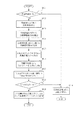
本実施形態で実行される画像処理手順を、図3を用いて説明する。
【0012】
ステップS301では、スキャナなどで紙文書を読み取って画像データを生成し、該画像データがコンピュータに入力される。
【0013】
ステップS302では、前処理部102において、画像データを後段の領域分割処理を実行するのに適した二値画像に変換する。具体的には、入力された画像データがカラーやグレースケールなどの多値画像の場合、適応的に閾値を設定して白黒の2値(なお、本実施形態では黒画素の画素値を1、白画素の画素値を0として扱う)に変換する二値化処理や、また孤立点などを除去するノイズ除去処理をおこなう。さらに、画像の領域分割処理を高速に行うため、入力された画像データのサイズを適正な画像サイズに変更する処理(文書画像の解像度変換)を行うようにしてもよい。例えば、画像解像度を1/2に縮小するなら2×2範囲(1/4の縮小なら4×4範囲)の画素がすべて0の場合は代表画素値0にし、それ以外の場合は画素値を1とするOR縮小によっておこなわれる。
【0014】
ステップS303では、領域分割処理103における画素塊抽出処理1031が実行され、二値画像から黒画素、白画素のかたまりを再帰的に抽出し、ツリー状の構造を作成する。この画素塊抽出処理について、図4のフローチャートを用いて詳細に説明する。
【0015】
ステップS401では、画像から黒画素の8連結輪郭塊の抽出を行う。黒画素塊を抽出できた場合はS402に進み、抽出できなかった場合はS408へ進む。なお、黒画素の8連結輪郭塊とは、縦横斜めのいずれかで接触した黒画素を検知して黒画素集合の輪郭を追跡することによって抽出した黒画素の集合(領域)のことである。以降、この集合を黒画素塊と呼ぶ。なお、この黒画素塊は、輪郭以外の画素の白黒は問わず、内部に白画素の空洞を有しても構わない。なお、この黒画素の輪郭追跡方法については、公知の方法を用いることが可能であり、以下に、図5を用いてこの黒画素塊抽出処理の概要を簡単に説明する。
【0016】
ステップS501では、(白画素値0、黒画素値1で構成される)二値画像を左上から順にラインスキャンし、画素値が1となる点(黒画素)を探す。例えば、図8の801の矢印で示したような順番で、ライン順に走査して黒画素を探す。
【0017】
ステップS502では、黒画素が見つかったかどうか判断し、黒画素が見つかったときは、当該黒画素を開始点ならびに注目点QとしてステップS503に進んで輪郭抽出の処理を開始する。一方、S502で見つからなかった場合は終了する。例えば、図8では画素810が開始点で且つ最初の注目点Qとなる。
【0018】
ステップS503では、直前の追跡方向d(直前の画素から注目点Qに追跡してきた方向)と周辺画素状態とに基づき、図11の表に記載した順序で周囲の画素の検査を行うことにより、注目点Qから次の輪郭画素への追跡方向d’を定める。ここで追跡方向は、図10に示したように、N,NE,E,SE,S,SW,W,NWの8方向で表すものとする。また例外処理として、最初の注目点Q(開始点)では、直前の追跡方向dはSEであったものと定義する。図11に示した表は、直前の追跡方向dに対して注目点Qの周囲の画素を検査する順序nを示している。例えば、直前の追跡方向dがSWであった場合は、注目点Qから見て、NW方向の画素から順に反時計回りに周囲の画素を検査していき(NW方向画素、W方向画素、SW方向画素・・・の順に検査)、黒画素が見つかった時点で周囲の画素の検査を終了して、その黒画素が見つかった方向を次の追跡方向d’とする。図11に示したような順序で検査することにより、次の追跡方向d’を定める際には、直前の追跡方向dを定める際に検査した画素の検査を行わないようにしている。
【0019】
ステップS504では、注目点Qの画素に輪郭画素であることを示すラベル付けをおこなう。ラベルには、“A”、“B”、“C”、“D”の4種類があり、輪郭で囲まれる領域において、画素行の左端のエッジとなる画素にはラベルAが付与され、右端のエッジとなる画素にはラベルBが付与され、左右両方のエッジとなっている画素にはラベルCが付与され、左右のどちらのエッジでもない輪郭画素にはラベルDが付与されるものとする。このラベル値は、図11と図12を用いて、直前の追跡方向dと次の追跡方向d’と現在のQのラベル値から決定される。
【0020】
ステップS505では、次の追跡方向d’にある画素を、新たな注目点Qとし、追跡方向d’を直前の追跡方向dに代入する。
【0021】
ステップS506において、新たな注目点Qが開始点に等しいかどうか判断し、等しい場合はステップS507に進み、等しくなければステップS503へ戻って追跡処理を繰り返す。
【0022】
ステップS503〜506で実行される処理について、図8の801を例にとって示す。まず、開始点810を最初の注目点Qとし、図11に記載された順に、方向SWから検査を始める。ここで最初の注目点Q(810)からは、次の追跡方向d’=SW(n=1)において黒画素が見つかり、図12を参照して、注目点Q(画素810)にラベル“A”が付与された後、注目点Qは左下に移動する。以下同様に繰り返すと図8の802のようなラベル付けがされた輪郭が得られる。
【0023】
ステップS507では、注目点Q(開始点)に他の分岐が存在するかどうかを調べる。他の分岐が存在するかどうかの判断は直前の追跡方向dがNEの場合に行われ、直前の追跡方向がNE以外の場合は他の分岐は存在しないと判断する。直前の追跡方向dがNEの場合、当該注目点Qの周囲の画素について、Qから見てSE方向の画素、E方向の画素の順で黒画素が存在するか検査を行い、黒画素が存在した時点で他の分岐が存在すると判断し、その存在した方向d’に注目点Qを移動させるとともに追跡方向d’を直前の追跡方向dに代入してステップS503に戻る。一方、他の分岐が存在しない場合はステップS509に進む。
【0024】
ステップS509では、輪郭ラベル付けされた黒画素にかこまれる画素の塊を1個の黒画素塊として記録する。具体的には、図8の803のように、各y座標(各画素行)毎に、左エッジラベル“A”と右エッジラベル“B”の組に挟まれた連続画素、あるいは単独の“C”画素を1セグメントとし、それらセグメントの集合として画素塊を記録する。なお、図8の803では、説明を容易にするために、x座標とy座標は黒画素塊に外接する矩形の左上の点を原点にしているが、好適には、x座標とy座標はS302で縮小した画像の左上を原点にして表すものとする。
【0025】
なお、1つの画素塊を抽出終了後(S509での処理終了後)、該抽出した画素塊にS402〜S407による属性分類が行なわれた後、S501に戻り、前回の開始点の右隣りの画素からラインスキャンを再開して次の開始点を探索する。ただし、その時点までで得られている黒画素塊の輪郭内部の画素については探索をスキップする、すなわち既出の黒画素塊が持つセグメントと重なる画素を無視して、画素値=“1”の画素を探す。
【0026】
図4の説明に戻ると、S401での処理(図5の処理)で抽出された全ての黒画素塊に対して、各黒画素塊の形状と各黒画素塊に外接する外接矩形の形状とを用いて、S402以降の処理において属性を分類する。
【0027】
ステップS402では、黒画素塊の外接矩形サイズが、予め予想される最大文字高さおよび幅に対し定められた閾値以下の大きさであった場合、文字要素と判定する。この黒画素塊には“CHAR”という属性を付加する。
【0028】
ステップS403では、黒画素塊の外接矩形サイズが、所定の比率以上で縦長あるいは横長であった場合、“LINE”の属性を与える。
【0029】
ステップS404では、黒画素塊中の黒画素のなす輪郭に注目し、その形状が細い斜めの線状であると判定した場合、“LINE”の属性を与える。
【0030】
ステップS405では、“CHAR”、“LINE”以外の黒画素塊の内部に存在する白画素の4連結輪郭塊を抽出する。白画素の4連結輪郭塊とは、縦横に連結した白画素の輪郭で囲まれる画素集合のことである。以降この集合を白画素塊と呼ぶ。
【0031】
白画素塊を抽出する方法は、図5で説明した黒画素の輪郭抽出処理において、“0”と“1”を逆転し、且つ、斜め方向の連結は考慮せずに、白画素は縦又は横(N,E,S,W)の4方向の連結のみを許可して輪郭を抽出する。さもないと白画素の輪郭追跡中に、注目点がベースとなる黒画素塊の外部に出てしまうからである。この制限のため、図5のS503に相当する処理においては、図11、12のテーブルにおいて、追跡方向が斜め方向の判断は行わずに同様の処理を行う。なお、図11、12のテーブルの代わりに白画素輪郭追跡用のテーブルを用意しても良く、この場合は追跡方向が4方向しか存在しないので非常に小さなテーブルとなる。
【0032】
ステップS406では、黒画素の輪郭形状がほぼ四角形かどうかを調べ、ほぼ四角形ならばステップS407に進む。四角形でなければ、黒画素塊を“NONCHAR”と判定する。四角形の黒画素塊および四角形以外の黒画素塊の例を図13に示す。
【0033】
ステップS407では、ほぼ四角形と判断された黒画素塊の内部から抽出される白画素塊の形状全てがほぼ長方形であり、且つそれらが黒画素塊の内部をほぼ隙間なしに占めている場合(白画素塊の外接矩形同士が重なることなく整然と並んでいる場合)、白画素塊の整列が良、とする。そして、内部白画素塊の整列が良い黒画素塊には、“TABLE”の属性を与え、一方、整列が悪い黒画素塊は“NONCHAR”の属性を与える。図14に、内部白画素塊の整列の例を示す。図14(a)および(b)は内部白画素塊の整列が良いとして“TABLE”と分類される黒画素塊の例であり、図14(c)は内部白画素塊の整列が悪いとして“NONCHAR”と分類される黒画素塊の例である。
【0034】
ステップS408では、“NONCHAR”あるいは“TABLE”と分類された黒画素塊内部にある白画素塊に注目し、さらにその白画素塊内部を対象にして、S401と同様に黒画素塊の抽出処理を行ってS402〜S407と同様の分類処理をおこなう。
【0035】
このS401〜S408の処理によって、画像内の黒画素塊、ならびに黒画素塊中の白画素塊、さらに、“TABLE”や“NONCHAR”内部の白画素塊から再帰的に黒画素塊が抽出される。
【0036】
図4のような処理を行って得た黒画素塊および白画素塊に対して、各画素塊内部に存在する画素塊を子ノードとして、ツリー構造を作成する。このときツリー構造において、黒画素塊についてはS402〜S407で分類された属性をつけて表し、白画素塊については“WHITE”の属性で表すものとする。例えば、図15に対して画素塊抽出をおこなうと、図16のようなツリー構造を持ったデータが得られる。なお、図16では図を簡略化するため、画素塊の個数などは一部省略してあるが、実際には多数の画素塊によるノードが存在するものとする。図16のツリーにおいて、“WHITE”ノードに相当するのは前記白画素塊であり、また、便宜上、ツリーのルートには画像全体に相当する“WHITE”の属性を与えてある。つまり、図16のようなツリー構造において、“WHITE”属性を後景と考え、その他の“CHAR”“TABLE”“LINE”などの属性を前景と考えると、図16のツリー構造において、親ノードと子ノードは、後景と前景が交互に出現することになる。なお、ツリー構造の各ノードには、画素塊の領域情報(セグメント情報)と属性とが含まれているものとする。
【0037】
以上説明したように画素塊のツリー構造を得た後、図3のステップS304において、領域分割部103の追加処理として、画素塊ツリー構造中の“NONCHAR”あるいは“TABLE”の属性が付与された黒画素塊に注目し、この黒画素塊内において黒下地上にある反転文字の抽出を目的とする画素塊抽出をおこなう。以下、具体的な処理例について、図6を用いて説明する。
【0038】
ステップS601では、注目する黒画素塊(黒画素塊Aとする)の形状的な特徴から、黒画素塊A内に反転文字が存在する可能性を類推する。ここでは、黒画素密度が著しく低い場合、すなわち線の骨組のような黒画素塊については、反転文字を含まないと判断する。なお、黒画素密度とは、黒画素塊の全セグメント(図8の803で示されるような黒画素塊の領域)の総画素数をPとしたとき、{(黒画素塊の全セグメントにおいて画素値が1の数)/P}で求められる値である。このような黒画素密度などの容易に計算できる処理を用いて、反転文字が存在する可能性が著しく低いと判断できる場合は、S602〜S608のような複雑な解析処理をスキップできるので、処理を速く行うことができる。
【0039】
ステップS602では、黒画素塊A内部の画素の画素値(0と1)を反転した画像Rを作成する。このとき、黒画素塊Aの輪郭をなす画素については、反転せずに画素値を1のままとする。図17に画像R作成の例を示す。
【0040】
なお、S302において縮小を施した画像を用いてS303の領域分割処理(画素塊抽出)を行っていた場合、ステップS602においては、縮小前の元画像から当該注目している黒画素塊の領域に対応する領域を抽出し、該抽出した領域に対して画素値(0と1)の反転を行い(ただし輪郭の画素は反転しない)、その反転が行なわれた抽出領域に対してOR縮小処理を施して得られる画像を、反転画像Rとする。このようにしないと、領域分割処理でOR縮小が行なわれた画像においては反転文字部分がつぶれてしまっている可能性が高いためである。このように、縮小前の画像を反転してから縮小するので、反転文字部分がつぶれたり、かすれたりすることを防ぐことができる。
【0041】
ステップS603では、反転画像Rの内部に対して、S405と同様の処理を行って白画素の4連結輪郭塊(白画素塊集合B)を抽出する。
【0042】
ステップS604では、ステップS603で抽出された白画素塊集合Bの内部から、黒画素塊(黒画素の8連結輪郭塊)を抽出する。抽出された黒画素塊集合をCとする。
【0043】
ステップS605では、反転前の黒画素塊A内部の白画素塊集合を抽出し、その反転前黒画素塊A内部の白画素塊集合のうち、所定以上の大きさを持つ白画素塊については反転文字(白抜き文字)ではないと判断し、ステップS604で得た黒画素塊集合Cと比較して、該所定以上の大きさを持つ白画素塊と座標上で重なる黒画素塊を集合Cから取り除く。このように反転前の黒画素塊A内部から白画素塊を抽出して判断するので、反転文字ではなく背景部分であるとして予め容易に判断できる。また、元画像をそのままOR縮小した画像内の黒画素塊A内においては、白画素塊が潰れることはあったとしても、元画像で分離していた白画素塊同士が1つの白画素塊として結合してしまうことはないので、背景と判断される部分を正確に取り出すことができる(一方、元画像を反転してから縮小した画像において黒画素塊を抽出した場合、元画像で分離していた白画素塊同士が結合して黒画素塊となっている可能性があるので、元画像の白画素背景部分と反転文字部分が近いと結合してしまう可能性があり、その場合反転文字も除外されてしまう可能性があるので、S605では反転前の黒画素塊Aから白画素塊を抽出している)。
【0044】
ステップS602〜S605で行なわれる処理の例を図9に示す。元画像901に対し、S302でOR縮小された画像からS303の領域分割処理で抽出された黒画素塊が910であった場合、この黒画素塊に対応する領域の元画像を反転・縮小して作成した反転画像が920である。黒画素塊910の内部にある白画素塊の領域912(反転画像920上では白画素塊921内部の黒画素塊922となって抽出される)は、明らかに反転文字でないと判断される場合(例えば、予め定めておいた所定サイズより大きいとき反転文字ではないと判断される)、この黒画素塊922は白画素塊912と位置的に重なるので除外される処理が行われる。この結果、反転文字部分に相当する黒画素塊集合923は残る。
【0045】
ステップS606では、集合C中の黒画素塊をS402と同等の判定規準(所定の閾値以下かどうか)で“CHAR”とそれ以外に分類する。
【0046】
ステップS607では、“CHAR”黒画素塊を大きさが微少なものとそうでないものに分ける。個数をそれぞれN,Mとする。
【0047】
ステップでは、Nをノイズに由来する画素塊の個数とみなし、それ以外の画素塊個数Mとの比較によって、画素塊が文字集合であるか否かを判断する。ここでは、M=0またはN/Mが所定の比率T以上の場合、画素塊は文字でないとしてS610に進む。それ以外の場合はS609にすすむ。
【0048】
ステップS609では、“CHAR”黒画素塊を反転文字の画素塊として、白画素塊を親ノードとするツリー構造を作成し、元の黒画素塊Aの直下に追加するよう画素塊ツリーを更新する。なお、親ノードとした白画素塊は、白画素塊Bをそのまま使ってもよいし、反転文字の画素塊に外接するような範囲を白画素塊として定義してもよい。
【0049】
このように白画素塊を親ノードとすることにより、親ノードと子ノードの関係において後景と前景が交互に出現するというツリー構造の特性を保ったまま、反転文字をツリー構造の前景として追加することができる。
【0050】
図15の例において、1501,1502,1503の3つの黒画素塊を対象に反転文字抽出判断処理をおこなって、ノイズ比などから判断して1501と1503から反転文字の画素塊が抽出された場合、図16のツリーは図18のように更新される。このとき挿入される仮想的な白画素塊は、反転文字の下地であるという情報が含まれている以外は通常の“WHITE”と同等に扱われる。本実施形態では、“WHITE(R)”と書くことにする。
【0051】
図3に戻り、ステップS305では、領域決定部1033が、画素塊のツリー構造およびその分類結果を利用し、画像を文字/画像/表/線など矩形状の領域へと分割する。なお、ステップS303で抽出された画素塊とステップS304で追加された画素塊は、ツリー構造の特性を保っているので、区別なく同様の処理で分割することができる。この画素塊の分類、領域化の処理を、図7を用いて説明する。
【0052】
ステップS701では、“CHAR”と分類された画素塊に注目し、縦あるいは横に一定距離内にあるものをグループ化していく。このグループを囲む矩形を各々文字領域とする。さらに、文字領域内で文字列が横方向であるか縦方向であるかを調べる。たとえば、領域内の各画素塊から左右の最近傍の画素塊への水平距離、および上下最近傍の画素塊への垂直距離を求め、それらの平均値が小さいほうが文字列の方向とすればよい。
【0053】
ステップS702では、“NONCHAR”画素塊のうち、同程度の大きさで縦または横に連なっている集合を検出し、これをグループ化してタイトル文字領域とする。
【0054】
ステップS703では、“NONCHAR”画素塊のうち、輪郭内の黒画素と白画素の比が小さい、すなわち黒画素密度の低いものを抽出し、これを線画領域とする。
【0055】
ステップS704では、“NONCHAR”画素塊のうち、黒密度が高く大きな画素塊、あるいはある領域に群をなしている画素塊をグループ化したものをハーフトーン領域とする。ハーフトーン領域とは、写真など中間調の領域である。ハーフトーン領域に“CHAR”や“LINE”の画素塊が含まれる場合は、各々の元の領域を破棄してハーフトーン領域に統合する。
【0056】
ステップS705では、“LINE”画素塊を囲む矩形を、線領域とする。
【0057】
ステップS706では、“TABLE”領域を含む矩形を、表領域とする。
【0058】
以上の処理を、すべての黒画素塊に対しておこなう。ただしグループ化の対象は1つの“WHITE”画素塊の内部に存在する黒画素塊集合ごととする。
【0059】
例えば、図21の画像から図18のような画素塊のツリー構造が得られたとすると、更にS701〜S706の処理を行って、図19のような属性毎の領域が決定される。このとき、画素塊ツリーの構成を元にして、領域間には図20の領域ツリー構造が作成される。この領域分割処理の出力結果においては、各領域の座標情報とともに、自分の親となる領域と、子供が存在すればそれらの領域へのリンク情報を保持する。
【0060】
なお、図19において、斜線塗りのテキスト領域は、反転文字として抽出されたテキスト領域である。これは出力結果からも図20のツリー構造において、WHITE(R)の下にあるテキストであることから判別できる。しかしながら、S701〜S706の処理は反転領域を区別することなく行われるので、判定アルゴリズムなどは非反転領域・反転領域のどちらにも共通にすることができる。
【0061】
【発明の効果】
以上説明したように、反転文字(白抜き文字)も、通常の文字と同じ階層ツリー構造で管理することができる。
【0062】
また、紙をスキャンして得た画像を、文字や図、写真、表など異なる性質の部分要素に分割する領域分割処理を行う際に、白地に黒の文字領域と同様の領域抽出手法を利用して、黒地に白の文字領域も抽出することができる。
【図面の簡単な説明】
【図1】第1の実施形態の構成を示すブロック図である
【図2】第1の実施形態を実現する装置構成例の図である
【図3】第1の実施形態の領域分割処理を説明するためのフローチャートである
【図4】画素塊抽出処理を説明するためのフローチャートである
【図5】黒画素の輪郭追跡処理を説明するためのフローチャートである
【図6】反転文字抽出処理を説明するためのフローチャートである
【図7】領域分類処理を説明するためのフローチャートである
【図8】輪郭追跡による画素塊抽出処理の例である
【図9】反転文字抽出処理の例である
【図10】8つの追跡方向を示す図である
【図11】追跡方向を決定するための表である
【図12】注目画素に対し付与するラベルを得るための表である
【図13】四角形の黒画素塊とそれ以外の黒画素塊の例を示す図である
【図14】黒画素塊内部の白画素塊の整列状態例を示す図である
【図15】領域分割処理の入力となる二値画像の例である
【図16】画素塊のツリー構造の例を示す図である
【図17】反転文字抽出の為に作成される画像の例である
【図18】反転文字を付与した画素塊のツリー構造の例を示す図である
【図19】反転文字部を含む領域分割処理結果の例である
【図20】反転文字部を含む領域のツリー構造の例である
【図21】領域分割をおこなう文書原稿の例である
【図22】従来の領域分割結果の例である
【図23】従来の領域ツリー構造の例である[0001]
BACKGROUND OF THE INVENTION
The present invention relates to an image processing method, apparatus, and program.
[0002]
[Prior art]
In recent years, computerization of information has progressed, and there is an increasing demand for mutual conversion between paper documents and computerized documents. When a paper document is digitized, the paper image is not only converted into image data by simply photoelectrically converting the paper surface with a scanner, etc., but the document image is converted into text, symbols, figures, photographs, It is divided into areas with different properties, such as tables, character code information for characters, figures and lines, table frames for vector data, photographs for image data, and table contents for structure data. It is desirable to convert it into data.
[0003]
In this way, in the digitization processing of paper documents, the content written in the document image is analyzed and divided into subregions with different properties such as characters, diagrams, photographs, and tables, that is, the importance of region division processing Is expensive.
[0004]
[Problems to be solved by the invention]
With regard to this area division processing method, for example, a document image read in multiple values (gray scale or color) as shown in FIG. 21 is converted into a binary image based on a luminance difference, and black pixels existing therein are converted. By extracting all pixel blocks in the outline, classifying them into characters and non-characters based on size, etc., and then recursively searching for pixels from within the white pixel area that exists within the large non-character black pixel block It has been proposed to express the state of a pixel block in a hierarchical tree structure as shown in FIG. In this tree structure of pixel blocks, character pixel blocks in the same hierarchy are grouped to obtain character areas, and drawings and photo areas are obtained from the shape and peripheral conditions of non-character pixel blocks to form a hierarchy. By dividing into areas having various attributes by processing such as obtaining a table area as a set of pixels, an area division result as shown in FIG. 22 can be obtained. Further, at this time, each area has a tree structure as shown in FIG. 23, so that the information is suitable for determining the logical structure of the document.
[0005]
However, in such area division processing, due to the processing configuration, the luminance inversion character portion included in FIG. 21, that is, a character (such as a character composed of white pixels on the black ground instead of black on the white background on the binary image). It is not easy to extract a region of inverted characters and white characters. In addition, it is considered that by comparing the number of black and white pixels and judging that there are many black pixels, it is possible to recognize inverted characters by inverting the pixels, but to obtain the relationship between normal characters and inverted characters It was difficult, and it was impossible to obtain a tree structure in which normal characters and inverted characters of the document were treated in an integrated manner from a document containing both.
[0006]
[Means for Solving the Problems]
In order to solve the above problems, the present inventionIn the image processing method, the first pixel block extracting unit recursively extracts the black pixel block and the white pixel block from the binary image and records them in the storage unit, and the tree structure generating unit includes the first A step of creating tree structure data indicating a positional relationship between a black pixel block and a white pixel block extracted by one pixel block extraction unit and recorded in the storage unit; A step of creating a reverse image by reversing the inside of a black pixel block that may include a reverse character among the black pixel blocks included, and generating a reverse image; and a second pixel block extraction means is the reverse created by the reverse image creation means A step of extracting a white pixel block and a black pixel block from an image; and the tree structure adding means includes data relating to the white pixel block and the black pixel block extracted by the second pixel block extraction unit, Corresponding node of structure data The inverted image creating means does not create a reversed image for a black pixel block having a low black pixel density among black pixel blocks included in the tree structure data. .
In order to solve the above problems, an image processing apparatus according to the present invention includes a first pixel block extraction unit that recursively extracts a black pixel block and a white pixel block from a binary image, and the first pixel block extraction unit. A tree structure creation means for creating tree structure data indicating a positional relationship between the black pixel block and the white pixel block extracted in step (b), and a black pixel block that can include inverted characters among the black pixel blocks included in the tree structure data. A reverse image creation means for creating a reverse image by reversing the inside of the image in black and white; a second pixel block extraction means for extracting a white pixel block and a black pixel block from the reverse image created by the reverse image creation means; Tree structure adding means for adding data relating to the white pixel block and the black pixel block extracted by the second pixel block extracting unit to a corresponding node of the tree structure data, and the inverted image generating unit Then, the tree structure data Of black pixel block included in the inverted image of the black pixel density is about low black pixel blocks is characterized in that it does not create.
In order to solve the above problems, an image processing program according to the present invention includes a first pixel block extraction unit that recursively extracts a black pixel block and a white pixel block from a binary image and records them in a storage unit. Tree structure creation means for creating tree structure data indicating the positional relationship between black pixel blocks and white pixel blocks extracted by the first pixel block extraction unit and recorded in the storage unit, and generated by the tree structure generation unit Inverted image creation means for creating a reverse image by reversing the inside of a black pixel block that may contain reverse characters among black pixel blocks included in the tree structure data, and a reverse image created by the reverse image creation means Second pixel block extracting means for extracting a white pixel block and a black pixel block, and data relating to the white pixel block and the black pixel block extracted by the second pixel block extracting unit, Corresponding notes An image processing program for functioning as a tree structure adding means to be added to a node, wherein the inverted image creating means is configured to process a black pixel block having a low black pixel density among black pixel blocks included in the tree structure data. The reverse image is not created.
[0007]
DETAILED DESCRIPTION OF THE INVENTION
FIG. 1 shows a block diagram of this embodiment.
[0008]
101 is an input unit for inputting image data generated by photoelectrically converting a paper document, 102 is a preprocessing unit for performing preprocessing such as binarization, reduction, and noise removal on the input image data, 103 Is an area dividing unit that divides image data into areas for each attribute such as characters, lines, diagrams, and tables. The
[0009]
FIG. 2 shows an overview of an apparatus configuration for realizing the present embodiment. The
[0010]
Note that a computer device that executes this embodiment stores a CPU that performs actual processing operations, a RAM that reads a program and uses it as a work area, a program for executing processing corresponding to a flowchart described later, and various data. Storage media (hard disk, ROM, removable disk (floppy (R) disk, CD-ROM, etc.)), keyboard and pointing device for performing various operations, display for displaying documents to be processed, network, and the like It consists of a network interface for connection. An image processing program to be executed by the CPU may be supplied from the storage medium or read from an external device via a network. In this embodiment, it is realized by executing a program in the CPU, but part or all of the processing may be configured by hardware (electric circuit).
[0011]
An image processing procedure executed in this embodiment will be described with reference to FIG.
[0012]
In step S301, a paper document is read by a scanner or the like to generate image data, and the image data is input to the computer.
[0013]
In step S302, the preprocessing
[0014]
In step S303, a pixel
[0015]
In step S401, eight connected contour blocks of black pixels are extracted from the image. If the black pixel block can be extracted, the process proceeds to S402, and if it cannot be extracted, the process proceeds to S408. Note that the 8-connected outline block of black pixels is a set (area) of black pixels extracted by detecting black pixels that are in contact with each other either vertically or horizontally and tracking the outline of the black pixel set. Hereinafter, this set is referred to as a black pixel block. The black pixel block may have white pixel cavities inside, regardless of whether the pixels other than the outline are black and white. As the black pixel outline tracking method, a known method can be used, and the outline of the black pixel block extraction process will be briefly described below with reference to FIG.
[0016]
In step S501, a binary image (comprising a white pixel value of 0 and a black pixel value of 1) is line-scanned in order from the upper left, and a point (black pixel) having a pixel value of 1 is searched. For example, a black pixel is searched by scanning in the order of lines in the order indicated by the
[0017]
In step S502, it is determined whether a black pixel is found. If a black pixel is found, the process proceeds to step S503 with the black pixel as a start point and a point of interest Q, and the contour extraction process is started. On the other hand, if not found in S502, the process ends. For example, in FIG. 8, the
[0018]
In step S503, based on the previous tracking direction d (the direction tracked from the previous pixel to the point of interest Q) and the surrounding pixel state, the surrounding pixels are inspected in the order shown in the table of FIG. A tracking direction d ′ from the attention point Q to the next contour pixel is determined. Here, as shown in FIG. 10, the tracking direction is represented by eight directions of N, NE, E, SE, S, SW, W, and NW. As exception processing, at the first attention point Q (start point), it is defined that the immediately preceding tracking direction d is SE. The table shown in FIG. 11 shows the order n in which the pixels around the attention point Q are inspected with respect to the immediately preceding tracking direction d. For example, when the previous tracking direction d is SW, the surrounding pixels are inspected counterclockwise from the pixel in the NW direction as viewed from the point of interest Q (NW direction pixel, W direction pixel, SW In the order of direction pixels...), When the black pixel is found, the surrounding pixels are inspected, and the direction in which the black pixel is found is set as the next tracking direction d ′. By inspecting in the order as shown in FIG. 11, when determining the next tracking direction d ', the inspection of the pixels that were inspected when determining the immediately preceding tracking direction d is not performed.
[0019]
In step S504, the pixel at the point of interest Q is labeled to indicate that it is a contour pixel. There are four types of labels, “A”, “B”, “C”, and “D”. In the area surrounded by the outline, a label A is given to the pixel that is the left edge of the pixel row, and the right edge The label B is given to the pixels that are the edges of the pixel, the label C is given to the pixels that are both the left and right edges, and the label D is given to the contour pixels that are not the left and right edges. . This label value is determined from the previous tracking direction d, the next tracking direction d ', and the current Q label value using FIGS.
[0020]
In step S505, the pixel in the next tracking direction d 'is set as a new attention point Q, and the tracking direction d' is substituted for the immediately preceding tracking direction d.
[0021]
In step S506, it is determined whether or not the new attention point Q is equal to the start point. If equal, the process proceeds to step S507. If not equal, the process returns to step S503 to repeat the tracking process.
[0022]
The processing executed in steps S503 to S506 will be described by taking 801 in FIG. 8 as an example. First, the
[0023]
In step S507, it is checked whether another branch exists at the attention point Q (start point). Whether or not another branch exists is determined when the immediately preceding tracking direction d is NE, and when the immediately preceding tracking direction is other than NE, it is determined that no other branch exists. When the previous tracking direction d is NE, the pixels around the target point Q are inspected for black pixels in the order of pixels in the SE direction and pixels in the E direction when viewed from Q. At this point, it is determined that another branch exists, the point of interest Q is moved in the existing direction d ′, and the tracking direction d ′ is substituted for the immediately preceding tracking direction d, and the process returns to step S503. On the other hand, if no other branch exists, the process proceeds to step S509.
[0024]
In step S509, a block of pixels surrounded by black pixels labeled with an outline is recorded as one black pixel block. Specifically, as shown by 803 in FIG. 8, for each y coordinate (each pixel row), a continuous pixel sandwiched between a pair of a left edge label “A” and a right edge label “B”, or a single “ A C ″ pixel is defined as one segment, and a pixel block is recorded as a set of the segments. In FIG. 8 803, for ease of explanation, the x-coordinate and y-coordinate are based on the upper left point of the rectangle circumscribing the black pixel block, but preferably the x-coordinate and y-coordinate are Assume that the upper left of the image reduced in S302 is the origin.
[0025]
After extraction of one pixel block (after completion of the processing in S509), the extracted pixel block is subjected to attribute classification according to S402 to S407, and then the process returns to S501 and the pixel on the right side of the previous start point The line scan is resumed from and the next starting point is searched. However, for pixels inside the outline of the black pixel block obtained up to that point, the search is skipped, that is, a pixel with a pixel value = “1” is ignored, ignoring pixels that overlap with the segments of the previously described black pixel block Search for.
[0026]
Returning to the description of FIG. 4, the shape of each black pixel block and the shape of a circumscribed rectangle circumscribing each black pixel block are obtained for all black pixel blocks extracted in the process of S <b> 401 (the process of FIG. 5). Are used to classify the attributes in the processing after S402.
[0027]
In step S402, if the circumscribed rectangle size of the black pixel block is a size equal to or smaller than a threshold value determined in advance for the maximum character height and width, it is determined as a character element. An attribute “CHAR” is added to the black pixel block.
[0028]
In step S403, if the circumscribed rectangle size of the black pixel block is longer or longer than a predetermined ratio, the “LINE” attribute is given.
[0029]
In step S404, attention is paid to the outline formed by the black pixels in the black pixel block, and when it is determined that the shape is a thin diagonal line, the attribute "LINE" is given.
[0030]
In step S405, four connected outline chunks of white pixels existing inside the black pixel chunk other than “CHAR” and “LINE” are extracted. The 4-connected outline block of white pixels is a pixel set surrounded by the outlines of white pixels connected vertically and horizontally. Hereinafter, this set is called a white pixel block.
[0031]
The white pixel block is extracted by reversing “0” and “1” in the black pixel contour extraction processing described with reference to FIG. The contour is extracted by allowing only the connection in the four directions (N, E, S, W). Otherwise, the point of interest goes outside the black pixel block as a base during the contour tracking of the white pixel. Because of this limitation, in the processing corresponding to S503 in FIG. 5, the same processing is performed without determining whether the tracking direction is oblique in the tables in FIGS. A table for tracking white pixel contours may be prepared instead of the tables shown in FIGS. 11 and 12. In this case, since there are only four tracking directions, the table is very small.
[0032]
In step S406, it is checked whether or not the outline shape of the black pixel is substantially square. If it is almost square, the process proceeds to step S407. If it is not a rectangle, the black pixel block is determined as “NONCHAR”. An example of a rectangular black pixel block and a non-rectangular black pixel block is shown in FIG.
[0033]
In step S407, when all the shapes of the white pixel block extracted from the inside of the black pixel block determined to be substantially square are substantially rectangular and they occupy the black pixel block without any gaps (white When the circumscribed rectangles of the pixel block are arranged in an orderly manner without overlapping), the white pixel block is well aligned. A black pixel block having a good alignment of the inner white pixel block is given the attribute “TABLE”, while a black pixel block having a poor alignment is given the attribute “NONCHAR”. FIG. 14 shows an example of the alignment of the inner white pixel block. FIGS. 14A and 14B are examples of black pixel blocks classified as “TABLE” because the alignment of the internal white pixel block is good, and FIG. 14C shows that the alignment of the internal white pixel block is bad. It is an example of a black pixel block classified as “NONCHAR”.
[0034]
In step S408, attention is paid to the white pixel block inside the black pixel block classified as “NONCHAR” or “TABLE”, and the black pixel block extraction processing is performed in the same manner as in S401 for the inside of the white pixel block. Then, the same classification process as in S402 to S407 is performed.
[0035]
Through the processing in S401 to S408, a black pixel block is recursively extracted from the black pixel block in the image, the white pixel block in the black pixel block, and the white pixel block in “TABLE” or “NONCHAR”. .
[0036]
Pixels present in each pixel block with respect to the black pixel block and the white pixel block obtained by performing the processing as shown in FIG.massCreate a tree structure using as a child node. In this case, in the tree structure, the black pixel block is represented with the attribute classified in S402 to S407, and the white pixel block is represented by the attribute “WHITE”. For example, when pixel block extraction is performed on FIG. 15, data having a tree structure as shown in FIG. 16 is obtained. In FIG. 16, in order to simplify the drawing, the number of pixel blocks is partly omitted, but it is assumed that there are actually a plurality of pixel block nodes. In the tree of FIG. 16, the white pixel block corresponds to the “WHITE” node, and for convenience, the “WHITE” attribute corresponding to the entire image is given to the root of the tree. That is, in the tree structure as shown in FIG. 16, when the “WHITE” attribute is considered as the foreground and the other attributes such as “CHAR”, “TABLE”, and “LINE” are considered as the foreground, As for the child node, the foreground and the foreground appear alternately. Note that each node of the tree structure includes pixel block region information (segment information) and attributes.
[0037]
After obtaining the tree structure of the pixel block as described above, in step S304 of FIG. 3, the attribute “NONCHAR” or “TABLE” in the pixel block tree structure is added as an additional process of the
[0038]
In step S601, the possibility that an inverted character exists in the black pixel block A is inferred from the shape characteristic of the black pixel block of interest (referred to as black pixel block A). Here, if the black pixel density is significantly low, i.e. the frame of the lineNoSuch a black pixel block is determined not to include inverted characters. Note that the black pixel density is defined as {(pixels in all segments of the black pixel block) when P is the total number of pixels of all segments of the black pixel block (region of the black pixel block as indicated by 803 in FIG. 8). The value is a value obtained by (number of 1) / P}. When it can be determined that the possibility of the presence of inverted characters is extremely low by using such easily calculated processing such as the black pixel density, complicated analysis processing such as S602 to S608 can be skipped. Can be done fast.
[0039]
In step S602, an image R is created by inverting the pixel values (0 and 1) of the pixels inside the black pixel block A. At this time, the pixel value of the pixel forming the outline of the black pixel block A is kept at 1 without being inverted. FIG. 17 shows an example of creating the image R.
[0040]
If the region division processing (pixel block extraction) in S303 is performed using the image that has been reduced in S302, in Step S602, the region of the focused black pixel block is changed from the original image before reduction. The corresponding area is extracted, the pixel values (0 and 1) are inverted for the extracted area (the outline pixels are not inverted), and OR reduction processing is performed on the extracted area where the inversion is performed. The image obtained by applying is defined as a reverse image R. If this is not done, there is a high possibility that the reversed character portion is crushed in the image subjected to OR reduction in the region division processing. In this way, since the image before reduction is inverted and then reduced, it is possible to prevent the inverted character portion from being crushed or blurred.
[0041]
In step S603, the same process as in S405 is performed on the inside of the reverse image R to extract four connected outline blocks (white pixel block set B) of white pixels.
[0042]
In step S604, a black pixel block (eight connected contour blocks of black pixels) is extracted from the inside of the white pixel block set B extracted in step S603. Let the extracted black pixel block set be C.
[0043]
In step S605, a white pixel block set inside the black pixel block A before inversion is extracted, and among the white pixel block sets inside the black pixel block A before inversion, the white pixel block set having a predetermined size or more is inverted. It is determined that it is not a character (outlined character), and compared with the black pixel block set C obtained in step S604, a black pixel block that overlaps the white pixel block having a size greater than or equal to the predetermined size from the set C. remove. Thus, since the white pixel block is extracted from the inside of the black pixel block A before inversion and is determined, it can be easily determined in advance that it is not a reverse character but a background portion. Further, in the black pixel block A in the image obtained by OR reduction of the original image as it is, even if the white pixel block is crushed, the white pixel blocks separated in the original image are one white pixel block. Since they are not combined, it is possible to accurately extract the portion determined to be the background. (On the other hand, if the black pixel block is extracted from the original image and then reduced, the original image is separated. White pixel blocks may be combined to form a black pixel block, so if the white pixel background part of the original image and the inverted character part are close, there is a possibility of combining them. Since there is a possibility of being excluded, a white pixel block is extracted from the black pixel block A before inversion in S605).
[0044]
An example of processing performed in steps S602 to S605 is shown in FIG. When the black pixel block extracted by the region dividing process of S303 from the image OR-reduced in S302 with respect to the
[0045]
In step S606, the black pixel block in the set C is classified into “CHAR” and other than that according to the determination criterion equivalent to S402 (whether it is equal to or less than a predetermined threshold).
[0046]
In step S607, the “CHAR” black pixel block is divided into a small size and a small size. The numbers are N and M, respectively.
[0047]
In the step, N is regarded as the number of pixel blocks derived from noise, and it is determined whether or not the pixel block is a character set by comparison with the number M of other pixel blocks. Here, if M = 0 or N / M is equal to or greater than the predetermined ratio T, the pixel block is not a character and the process proceeds to S610. Otherwise, proceed to S609.
[0048]
In step S609, a tree structure having a white pixel block as a parent node with the “CHAR” black pixel block as an inverted character pixel block is created, and the pixel block tree is updated to be added immediately below the original black pixel block A. . The white pixel block B as the parent node may use the white pixel block B as it is, or may define a range circumscribing the pixel block of the inverted character as the white pixel block.
[0049]
By using the white pixel block as the parent node in this way, the inverted character is added as the foreground of the tree structure while maintaining the characteristics of the tree structure that the foreground and foreground appear alternately in the relationship between the parent node and the child node. can do.
[0050]
In the example of FIG. 15, when reversed character extraction determination processing is performed for three black pixel blocks 1501, 1502, and 1503, and a pixel block of inverted characters is extracted from 1501 and 1503 as determined from a noise ratio or the like. 16 is updated as shown in FIG. The virtual white pixel block inserted at this time is handled in the same way as normal “WHITE” except that information indicating that it is the background of the inverted character is included. In this embodiment, “WHITE®” is written.
[0051]
Returning to FIG. 3, in step S <b> 305, the
[0052]
In step S701, attention is paid to the pixel block classified as “CHAR”, and pixels within a certain distance are grouped vertically or horizontally. Each rectangle surrounding this group is a character area. Further, it is checked whether the character string is in the horizontal direction or the vertical direction in the character area. For example, the horizontal distance from each pixel block in the region to the right and left nearest pixel block and the vertical distance to the top and bottom nearest pixel block may be obtained, and the smaller of these average values may be the direction of the character string .
[0053]
In step S702, among the “NONCHAR” pixel block, a set of the same size and connected vertically or horizontally is detected and grouped into a title character area.
[0054]
In step S703, a “NONCHAR” pixel block having a small ratio of black pixels to white pixels in the outline, ie, having a low black pixel density, is extracted as a line drawing area.
[0055]
In step S704, among the “NONCHAR” pixel blocks, a large pixel block having a high black density or a group of pixel blocks grouped in a certain region is set as a halftone region. The halftone area is a halftone area such as a photograph. When the halftone area includes a pixel block of “CHAR” or “LINE”, each original area is discarded and integrated into the halftone area.
[0056]
In step S705, a rectangle surrounding the “LINE” pixel block is defined as a line area.
[0057]
In step S706, a rectangle including the “TABLE” area is set as a table area.
[0058]
The above processing is performed for all black pixel blocks. However, grouping is performed for each set of black pixel blocks existing within one “WHITE” pixel block.
[0059]
For example, if the pixel block tree structure as shown in FIG. 18 is obtained from the image of FIG. 21, the processing of S701 to S706 is further performed to determine the region for each attribute as shown in FIG. At this time, the area tree structure of FIG. 20 is created between the areas based on the configuration of the pixel block tree. In the output result of this area division processing, the coordinate information of each area, the area that is its own parent, and link information to those areas if there are children are retained.
[0060]
In FIG. 19, the hatched text region is a text region extracted as an inverted character. This can also be determined from the output result because it is the text under WHITE (R) in the tree structure of FIG. However, since the processing of S701 to S706 is performed without distinguishing the inversion area, the determination algorithm and the like can be made common to both the non-inversion area and the inversion area.
[0061]
【The invention's effect】
As described above, inverted characters (outlined characters) can be managed in the same hierarchical tree structure as normal characters.
[0062]
In addition, when performing image segmentation processing that divides an image obtained by scanning paper into subelements with different properties such as characters, diagrams, photographs, and tables, the same region extraction method as a black character region on a white background is used. Thus, a white character region can be extracted on a black background.
[Brief description of the drawings]
FIG. 1 is a block diagram showing the configuration of a first embodiment
FIG. 2 is a diagram of an example of an apparatus configuration that realizes the first embodiment;
FIG. 3 is a flowchart for explaining region division processing according to the first embodiment;
FIG. 4 is a flowchart for explaining pixel block extraction processing;
FIG. 5 is a flowchart for explaining a contour tracking process of a black pixel;
FIG. 6 is a flowchart for explaining an inverted character extraction process;
FIG. 7 is a flowchart for explaining area classification processing;
FIG. 8 is an example of pixel block extraction processing by contour tracking;
FIG. 9 is an example of inverted character extraction processing;
FIG. 10 is a diagram showing eight tracking directions.
FIG. 11 is a table for determining a tracking direction.
FIG. 12 is a table for obtaining a label to be assigned to a target pixel.
FIG. 13 is a diagram illustrating an example of a rectangular black pixel block and other black pixel blocks;
FIG. 14 is a diagram illustrating an example of an alignment state of white pixel blocks inside a black pixel block;
FIG. 15 is an example of a binary image as an input for region division processing;
FIG. 16 is a diagram illustrating an example of a tree structure of a pixel block;
FIG. 17 is an example of an image created for reverse character extraction
FIG. 18 is a diagram illustrating an example of a tree structure of a pixel block to which inverted characters are added.
FIG. 19 is an example of a region division processing result including a reversed character part
FIG. 20 is an example of a tree structure of an area including an inverted character part
FIG. 21 is an example of a document manuscript that performs region division;
FIG. 22 is an example of a conventional area division result
FIG. 23 is an example of a conventional region tree structure
Claims (13)
ツリー構造作成手段が、前記第1の画素塊抽出手段で抽出されて前記記憶手段に記録された黒画素塊と白画素塊との位置関係を示すツリー構造データを作成するステップと、
反転画像作成手段が、前記ツリー構造データに含まれる黒画素塊のうち反転文字を含みうる黒画素塊の内部を白黒反転させて、反転画像を作成するステップと、
第2の画素塊抽出手段が、前記反転画像作成手段で作成された反転画像から、白画素塊と黒画素塊とを抽出するステップと、
前記ツリー構造追加手段が、前記第2の画素塊抽出手段で抽出された白画素塊と黒画素塊とに関するデータを、前記ツリー構造データの対応するノードに追加するステップとを有し、
前記反転画像作成手段では、前記ツリー構造データに含まれる黒画素塊のうち、黒画素密度が低い黒画素塊についての反転画像は作成しないことを特徴とする画像処理方法。 A first pixel block extraction means, and away step be recorded in the storage means by recursively extracts the black pixel blocks and white pixel pixel block from the binary image,
Tree structure creation means, the absence steps to create a tree structure data indicating a positional relationship between the first black pixel blocks that are recorded in the storage means is extracted with pixel block extraction unit and white pixel pixel block,
Inverted image creating means, and the inside of the black pixel block which may include a reversed character is black and white reversal of the black pixel blocks included in the tree structure data, and Luz step to create a reverse image,
A second pixel block extraction unit, from the inverted image created by said inverted image creating means, the answering step to extract and white pixel block and black pixel blocks,
Said tree structure addition means, data relating to said second pixel block white pixel blocks extracted by the extraction means and black pixel blocks, possess the absence steps to add to the corresponding node of the tree structure data,
The image processing method according to claim 1, wherein the inverted image creating means does not create an inverted image of a black pixel block having a low black pixel density among black pixel blocks included in the tree structure data .
前記反転画像とは、当該白黒反転させる対象の黒画素塊の領域と前記原画像を白黒反転させてからOR縮小することによって得た画像とに基づいて作成されることを特徴とする請求項1に記載の画像処理方法。The binary image is an image obtained by OR reduction of a binary original image,
2. The inverted image is created based on an area of a black pixel block to be subjected to monochrome inversion and an image obtained by performing OR reduction after the original image is inverted in black and white. An image processing method described in 1.
前記第1の画素塊抽出手段で抽出された黒画素塊と白画素塊との位置関係を示すツリー構造データを作成するツリー構造作成手段と、
前記ツリー構造データに含まれる黒画素塊のうち反転文字を含みうる黒画素塊の内部を白黒反転させて、反転画像を作成する反転画像作成手段と、
前記反転画像作成手段で作成された反転画像から、白画素塊と黒画素塊とを抽出する第2の画素塊抽出手段と、
前記第2の画素塊抽出手段で抽出された白画素塊と黒画素塊とに関するデータを、前記ツリー構造データの対応するノードに追加するツリー構造追加手段とを有し、
前記反転画像作成手段では、前記ツリー構造データに含まれる黒画素塊のうち、黒画素密度が低い黒画素塊についての反転画像は作成しないことを特徴とする画像処理装置。First pixel block extraction means for recursively extracting a black pixel block and a white pixel block from a binary image;
Tree structure creation means for creating tree structure data indicating the positional relationship between the black pixel block and the white pixel block extracted by the first pixel block extraction unit;
Inverted image creating means for creating an inverted image by reversing the inside of a black pixel block that may include inverted characters among black pixel blocks included in the tree structure data,
Second pixel block extraction means for extracting a white pixel block and a black pixel block from the reverse image generated by the reverse image generation unit;
Data relating to said second pixel block white pixel blocks extracted by the extraction means and black pixel blocks, possess a tree structure addition means for adding the corresponding node of the tree structure data,
The image processing apparatus according to claim 1, wherein the inverted image creation means does not create an inverted image of a black pixel block having a low black pixel density among black pixel blocks included in the tree structure data .
二値画像から黒画素塊と白画素塊とを再帰的に抽出して記憶手段に記録する第1の画素塊抽出手段、
前記第1の画素塊抽出手段で抽出されて前記記憶手段に記録された黒画素塊と白画素塊との位置関係を示すツリー構造データを作成するツリー構造作成手段、
前記ツリー構造作成手段で作成されたツリー構造データに含まれる黒画素塊のうち反転文字を含みうる黒画素塊の内部を白黒反転させて、反転画像を作成する反転画像作成手段、
前記反転画像作成手段で作成された反転画像から、白画素塊と黒画素塊とを抽出する第2の画素塊抽出手段、
前記第2の画素塊抽出手段で抽出された白画素塊と黒画素塊とに関するデータを、前記ツリー構造データの対応するノードに追加するツリー構造追加手段、
として機能させるための画像処理プログラムであり、
前記反転画像作成手段では、前記ツリー構造データに含まれる黒画素塊のうち、黒画素密度が低い黒画素塊についての反転画像は作成しないことを特徴とする画像処理プログラム。 The computer,
First pixel block extraction means for recursively extracting a black pixel block and a white pixel block from a binary image and recording them in a storage unit ;
Tree structure creation means for creating tree structure data indicating the positional relationship between the black pixel blocks and the white pixel blocks extracted by the first pixel block extraction unit and recorded in the storage unit ;
Inverted image creating means for creating an inverted image by reversing the inside of a black pixel block that may include inverted characters among black pixel blocks included in the tree structure data created by the tree structure creating unit ,
Wherein the inverted inverted image created by the image creation unit, the second pixel block extraction means for extracting a white pixel block and black pixel blocks,
Tree structure adding means for adding data relating to the white pixel block and the black pixel block extracted by the second pixel block extracting means to a corresponding node of the tree structure data ;
Is an image processing program for functioning as
An image processing program characterized in that the reverse image creation means does not create a reverse image for a black pixel block having a low black pixel density among black pixel blocks included in the tree structure data .
Priority Applications (6)
| Application Number | Priority Date | Filing Date | Title |
|---|---|---|---|
| JP2002285580A JP3950777B2 (en) | 2002-09-30 | 2002-09-30 | Image processing method, image processing apparatus, and image processing program |
| US10/667,413 US7298900B2 (en) | 2002-09-30 | 2003-09-23 | Image processing method, image processing apparatus and image processing program |
| DE60331624T DE60331624D1 (en) | 2002-09-30 | 2003-09-26 | Image processing method, apparatus and program for handling inverted letters |
| EP03256072A EP1403813B1 (en) | 2002-09-30 | 2003-09-26 | Image processing method, image processing apparatus and image processing program for dealing with inverted characters |
| CNB031598773A CN100474340C (en) | 2002-09-30 | 2003-09-26 | Image processing method and image processing device |
| US11/861,020 US8155445B2 (en) | 2002-09-30 | 2007-09-25 | Image processing apparatus, method, and processing program for image inversion with tree structure |
Applications Claiming Priority (1)
| Application Number | Priority Date | Filing Date | Title |
|---|---|---|---|
| JP2002285580A JP3950777B2 (en) | 2002-09-30 | 2002-09-30 | Image processing method, image processing apparatus, and image processing program |
Publications (3)
| Publication Number | Publication Date |
|---|---|
| JP2004126648A JP2004126648A (en) | 2004-04-22 |
| JP2004126648A5 JP2004126648A5 (en) | 2005-10-20 |
| JP3950777B2 true JP3950777B2 (en) | 2007-08-01 |
Family
ID=31973399
Family Applications (1)
| Application Number | Title | Priority Date | Filing Date |
|---|---|---|---|
| JP2002285580A Expired - Fee Related JP3950777B2 (en) | 2002-09-30 | 2002-09-30 | Image processing method, image processing apparatus, and image processing program |
Country Status (5)
| Country | Link |
|---|---|
| US (2) | US7298900B2 (en) |
| EP (1) | EP1403813B1 (en) |
| JP (1) | JP3950777B2 (en) |
| CN (1) | CN100474340C (en) |
| DE (1) | DE60331624D1 (en) |
Cited By (1)
| Publication number | Priority date | Publication date | Assignee | Title |
|---|---|---|---|---|
| US8395819B2 (en) | 2008-06-18 | 2013-03-12 | Canon Kabushiki Kaisha | Image processing device, image processing method and computer readable medium |
Families Citing this family (29)
| Publication number | Priority date | Publication date | Assignee | Title |
|---|---|---|---|---|
| JP4409897B2 (en) * | 2003-09-19 | 2010-02-03 | 株式会社リコー | Image processing apparatus, image processing method, program, and information recording medium |
| JP4111190B2 (en) * | 2004-12-24 | 2008-07-02 | コニカミノルタビジネステクノロジーズ株式会社 | Image processing device |
| JP4646797B2 (en) * | 2005-02-01 | 2011-03-09 | キヤノン株式会社 | Image processing apparatus, control method therefor, and program |
| JP4618676B2 (en) * | 2005-04-28 | 2011-01-26 | 株式会社リコー | Structured document code transfer method, image processing system, server device, program, and information recording medium |
| US7697149B2 (en) * | 2005-08-10 | 2010-04-13 | Kyocera Mita Corporation | System for detecting and avoiding printing of solid black areas |
| US7733524B2 (en) * | 2006-06-06 | 2010-06-08 | Primax Electronics Ltd. | Monochromic image processing system and method for background removal according to dynamic data |
| JP4807879B2 (en) * | 2006-06-21 | 2011-11-02 | 株式会社バンダイナムコゲームス | Image recognition apparatus, method, program, and information recording medium for extracting at least one recognition target image from input image data |
| JP4662066B2 (en) * | 2006-07-12 | 2011-03-30 | 株式会社リコー | Image processing apparatus, image forming apparatus, image distribution apparatus, image processing method, program, and recording medium |
| JP4241774B2 (en) * | 2006-07-20 | 2009-03-18 | カシオ計算機株式会社 | Image processing apparatus, image processing method, and program |
| US8107743B2 (en) * | 2007-03-30 | 2012-01-31 | Sharp Kabushiki Kaisha | Image processing device, image processing method, and storage medium |
| US8068684B2 (en) | 2007-05-04 | 2011-11-29 | I.R.I.S. | Compression of digital images of scanned documents |
| CN101551859B (en) * | 2008-03-31 | 2012-01-04 | 夏普株式会社 | Image recognition device and image retrieval device |
| JP5028337B2 (en) * | 2008-05-30 | 2012-09-19 | キヤノン株式会社 | Image processing apparatus, image processing method, program, and storage medium |
| JP5121599B2 (en) | 2008-06-30 | 2013-01-16 | キヤノン株式会社 | Image processing apparatus, image processing method, program thereof, and storage medium |
| US8351691B2 (en) * | 2008-12-18 | 2013-01-08 | Canon Kabushiki Kaisha | Object extraction in colour compound documents |
| JP5538967B2 (en) * | 2009-06-18 | 2014-07-02 | キヤノン株式会社 | Information processing apparatus, information processing method, and program |
| JP2011013898A (en) | 2009-07-01 | 2011-01-20 | Canon Inc | Image processing apparatus, image processing method, and program |
| JP5511450B2 (en) * | 2010-03-16 | 2014-06-04 | キヤノン株式会社 | Image processing apparatus, image processing method, and program |
| JP5733907B2 (en) | 2010-04-07 | 2015-06-10 | キヤノン株式会社 | Image processing apparatus, image processing method, and computer program |
| CN106454371B (en) | 2010-04-13 | 2020-03-20 | Ge视频压缩有限责任公司 | Decoder, array reconstruction method, encoder, encoding method, and storage medium |
| TWI678916B (en) | 2010-04-13 | 2019-12-01 | 美商Ge影像壓縮有限公司 | Sample region merging |
| CN106067984B (en) | 2010-04-13 | 2020-03-03 | Ge视频压缩有限责任公司 | Cross-plane prediction |
| ES2904650T3 (en) | 2010-04-13 | 2022-04-05 | Ge Video Compression Llc | Video encoding using multitree image subdivisions |
| US8467606B2 (en) * | 2011-08-25 | 2013-06-18 | Eastman Kodak Company | Method for segmenting a composite image |
| JP6236817B2 (en) | 2013-03-15 | 2017-11-29 | 株式会社リコー | Image forming apparatus |
| CN105354836B (en) * | 2015-10-14 | 2018-08-28 | 合肥安晶龙电子股份有限公司 | Color selection method |
| US9965871B1 (en) * | 2016-12-30 | 2018-05-08 | Konica Minolta Laboratory U.S.A., Inc. | Multi-binarization image processing |
| US11501551B2 (en) * | 2020-06-08 | 2022-11-15 | Optum Services (Ireland) Limited | Document processing optimization |
| CN117036364B (en) * | 2023-10-09 | 2024-01-02 | 全芯智造技术有限公司 | Image processing method and device, storage medium and computing equipment |
Family Cites Families (11)
| Publication number | Priority date | Publication date | Assignee | Title |
|---|---|---|---|---|
| JPS59142678A (en) | 1983-02-03 | 1984-08-15 | Ricoh Co Ltd | Frame recognizing system |
| JPH0656618B2 (en) | 1986-05-20 | 1994-07-27 | 国際電信電話株式会社 | Image information character / graphic separation method |
| JPH0528317A (en) * | 1991-07-23 | 1993-02-05 | Canon Inc | Method and device for processing image |
| JP3083673B2 (en) * | 1993-03-31 | 2000-09-04 | 株式会社東芝 | Image area identification device |
| JP3302147B2 (en) | 1993-05-12 | 2002-07-15 | 株式会社リコー | Document image processing method |
| JP2888270B2 (en) | 1993-11-30 | 1999-05-10 | 日本ビクター株式会社 | Graphic processing apparatus and method |
| US5588072A (en) * | 1993-12-22 | 1996-12-24 | Canon Kabushiki Kaisha | Method and apparatus for selecting blocks of image data from image data having both horizontally- and vertically-oriented blocks |
| US5987171A (en) | 1994-11-10 | 1999-11-16 | Canon Kabushiki Kaisha | Page analysis system |
| JP4077919B2 (en) * | 1998-01-30 | 2008-04-23 | キヤノン株式会社 | Image processing method and apparatus and storage medium therefor |
| JP4392907B2 (en) * | 1999-07-30 | 2010-01-06 | 株式会社東芝 | Character extraction method |
| JP4366011B2 (en) | 2000-12-21 | 2009-11-18 | キヤノン株式会社 | Document processing apparatus and method |
-
2002
- 2002-09-30 JP JP2002285580A patent/JP3950777B2/en not_active Expired - Fee Related
-
2003
- 2003-09-23 US US10/667,413 patent/US7298900B2/en not_active Expired - Fee Related
- 2003-09-26 EP EP03256072A patent/EP1403813B1/en not_active Expired - Lifetime
- 2003-09-26 DE DE60331624T patent/DE60331624D1/en not_active Expired - Lifetime
- 2003-09-26 CN CNB031598773A patent/CN100474340C/en not_active Expired - Fee Related
-
2007
- 2007-09-25 US US11/861,020 patent/US8155445B2/en not_active Expired - Fee Related
Cited By (1)
| Publication number | Priority date | Publication date | Assignee | Title |
|---|---|---|---|---|
| US8395819B2 (en) | 2008-06-18 | 2013-03-12 | Canon Kabushiki Kaisha | Image processing device, image processing method and computer readable medium |
Also Published As
| Publication number | Publication date |
|---|---|
| EP1403813B1 (en) | 2010-03-10 |
| US7298900B2 (en) | 2007-11-20 |
| US20080080769A1 (en) | 2008-04-03 |
| CN1497502A (en) | 2004-05-19 |
| US20040061883A1 (en) | 2004-04-01 |
| JP2004126648A (en) | 2004-04-22 |
| US8155445B2 (en) | 2012-04-10 |
| CN100474340C (en) | 2009-04-01 |
| EP1403813A3 (en) | 2005-07-20 |
| DE60331624D1 (en) | 2010-04-22 |
| EP1403813A2 (en) | 2004-03-31 |
Similar Documents
| Publication | Publication Date | Title |
|---|---|---|
| JP3950777B2 (en) | Image processing method, image processing apparatus, and image processing program | |
| JP4646797B2 (en) | Image processing apparatus, control method therefor, and program | |
| US6839466B2 (en) | Detecting overlapping images in an automatic image segmentation device with the presence of severe bleeding | |
| JP3308032B2 (en) | Skew correction method, skew angle detection method, skew correction device, and skew angle detection device | |
| JP5274495B2 (en) | How to change the document image size | |
| US7170647B2 (en) | Document processing apparatus and method | |
| JP4535584B2 (en) | Digital image processing method | |
| JP5854802B2 (en) | Image processing apparatus, image processing method, and computer program | |
| EP1017011A2 (en) | Block selection of table features | |
| JP4391704B2 (en) | Image processing apparatus and method for generating binary image from multi-valued image | |
| US6360006B1 (en) | Color block selection | |
| JP4538214B2 (en) | Image segmentation by graph | |
| JPH03126181A (en) | Area dividing method for document image | |
| JP2786355B2 (en) | How to determine the attributes of text images | |
| EP0974931A1 (en) | Method and apparatus for identifying a plurality of sub-images in an input image | |
| JP2789622B2 (en) | Character / graphic area determination device | |
| JP4409678B2 (en) | Ruled line extraction method | |
| KR100334624B1 (en) | Clustering based document image segmentation method | |
| JP4587167B2 (en) | Image processing apparatus and image processing method | |
| JP2877548B2 (en) | Document image attribute discrimination method | |
| JPH0535914A (en) | Picture inclination detection method | |
| JP2006345456A (en) | Image processing apparatus, method, program and storage medium | |
| JPH05282489A (en) | Method for deciding attribute of document image | |
| JP2002312794A (en) | Image processing method and its device | |
| JPH0535870A (en) | Contour point extracting method using multi-valued data |
Legal Events
| Date | Code | Title | Description |
|---|---|---|---|
| A521 | Request for written amendment filed |
Free format text: JAPANESE INTERMEDIATE CODE: A523 Effective date: 20050615 |
|
| A621 | Written request for application examination |
Free format text: JAPANESE INTERMEDIATE CODE: A621 Effective date: 20050615 |
|
| A131 | Notification of reasons for refusal |
Free format text: JAPANESE INTERMEDIATE CODE: A131 Effective date: 20070123 |
|
| A521 | Request for written amendment filed |
Free format text: JAPANESE INTERMEDIATE CODE: A523 Effective date: 20070326 |
|
| TRDD | Decision of grant or rejection written | ||
| A01 | Written decision to grant a patent or to grant a registration (utility model) |
Free format text: JAPANESE INTERMEDIATE CODE: A01 Effective date: 20070417 |
|
| A61 | First payment of annual fees (during grant procedure) |
Free format text: JAPANESE INTERMEDIATE CODE: A61 Effective date: 20070423 |
|
| R150 | Certificate of patent or registration of utility model |
Ref document number: 3950777 Country of ref document: JP Free format text: JAPANESE INTERMEDIATE CODE: R150 Free format text: JAPANESE INTERMEDIATE CODE: R150 |
|
| FPAY | Renewal fee payment (event date is renewal date of database) |
Free format text: PAYMENT UNTIL: 20110427 Year of fee payment: 4 |
|
| FPAY | Renewal fee payment (event date is renewal date of database) |
Free format text: PAYMENT UNTIL: 20130427 Year of fee payment: 6 |
|
| FPAY | Renewal fee payment (event date is renewal date of database) |
Free format text: PAYMENT UNTIL: 20130427 Year of fee payment: 6 |
|
| FPAY | Renewal fee payment (event date is renewal date of database) |
Free format text: PAYMENT UNTIL: 20140427 Year of fee payment: 7 |
|
| LAPS | Cancellation because of no payment of annual fees |