JP3943722B2 - Data transfer apparatus, data transfer system and method, image processing apparatus, and recording medium - Google Patents
Data transfer apparatus, data transfer system and method, image processing apparatus, and recording medium Download PDFInfo
- Publication number
- JP3943722B2 JP3943722B2 JP22068998A JP22068998A JP3943722B2 JP 3943722 B2 JP3943722 B2 JP 3943722B2 JP 22068998 A JP22068998 A JP 22068998A JP 22068998 A JP22068998 A JP 22068998A JP 3943722 B2 JP3943722 B2 JP 3943722B2
- Authority
- JP
- Japan
- Prior art keywords
- data
- buffer
- command
- transfer
- response
- Prior art date
- Legal status (The legal status is an assumption and is not a legal conclusion. Google has not performed a legal analysis and makes no representation as to the accuracy of the status listed.)
- Expired - Fee Related
Links
Images


Landscapes
- Small-Scale Networks (AREA)
- Communication Control (AREA)
- Information Transfer Systems (AREA)
- Computer And Data Communications (AREA)
Description
【0001】
【発明の属する技術分野】
本発明はデータ転送装置、データ転送システムおよびその方法、画像処理装置、並びに、記録媒体に関し、例えば、IEEE1394などにより規定されるシリアルインタフェイスを介して、画像供給デバイスと画像処理デバイスとを直結する場合のデータ転送装置、データ転送システムおよびその方法、画像処理装置、並びに、記録媒体に関するものである。
【従来の技術】
プリンタは、セントロニクスやRS232Cと言ったパラレルあるいはシリアルインタフェイスを介して、ホストデバイスであるパーソナルコンピュータ(PC)と接続されている。
【0002】
また、スキャナ、ディジタルスチルカメラ、ディジタルビデオカメラといった画像供給デバイスであるディジタル機器もPCに接続されている。各ディジタル機器により取込まれた画像データは、一旦PC上のハードディスクなどに取込まれた後、PC上のアプリケーションソフトウェアなどにより処理されてプリンタ用の印刷データに変換され、上記のインタフェイスを経由してプリンタに送られる。
【0003】
上記のようなシステムでは、各ディジタル機器やプリンタなどを制御するためのドライバソフトウェアがそれぞれ独立にPCに存在し、ディジタル機器から出力された画像データは、それらドライバソフトウェアによりPC上で使い易くかつ表示し易い形式のデータとして保存される。保存されたデータは、入力機器の画像特性と出力機器の画像特性とを考慮した画像処理方法により印刷データに変換される。
【0004】
今日、IEEE1394により規定されるインタフェイス(以下「1394シリアルバス」と呼ぶ)のような新しいインタフェイスでは、画像供給デバイスとプリンタとを直結することも可能である。1394シリアルバスにより画像供給デバイスとプリンタとを直結する場合、FCP(Function コントロール Protocol)のオペランドに印刷データを含める方法が考えられる。また、 1394シリアルバスでは、データ転送のためのレジスタ領域を設けて、そのレジスタ領域にデータを書込むことでデータ転送を行う方法も考えられる。
【0005】
また、データ転送の開始を指示するコマンドと、コマンドに対するレスポンスとを用いて、データ転送を指示する方法も考えられる。
【発明が解決しようとする課題】
しかし、上述した技術においては、次のような問題点がある。前述したように、画像供給デバイスから出力される画像データは、PCにより印刷データに変換されてプリンタにより印刷されるものであるから、画像供給デバイスとプリンタを直結したとしても、PCが無ければ印刷を行うことができない。ディジタルビデオカメラから出力される画像データを直接印刷するビデオプリンタと呼ばれるプリンタもあるが、特定の機種間で接続ができるだけであり、多数の画像供給デバイスと直結して使える汎用性の高いビデオプリンタはない。つまり、1394シリアルバスなどの特徴であるデバイス間を直結する機能を生かし、画像供給デバイスからプリンタへ画像データを直接送って印刷することはできない。
【0006】
1394シリアルバスにより画像供給デバイスとプリンタを直結し、FCPのオペランドに印刷データを含める前述した方法は、制御コマンドと印刷データとを分離することができない問題がある上、コマンドに対して常にレスポンスが必要なため転送効率が低いという問題もある。また、前述したデータ転送のためのレジスタ領域を設ける方法は、そのレジスタ領域にデータを書込むことが可能であるかどうかを判定するための処理がデータ転送の度に必要になる。従って、この判定処理のオーバヘッドが大きくなり、やはり転送効率が低下するという問題が発生する。
【0007】
この問題を解決するために、データとコマンドとを分離せずに同じレジスタ領域を用いる方法が考えられる。この方法では使われるレジスタ領域を減らすことができ、より簡単なデータ転送方式を提供できる。さらにデータを書き込むレジスタ領域が書き込み可能であるかどうかの判定は行わず、データをレジスタに書き込んだ後に、該書き込みに対する正否の応答のみを行い、成功の応答があれば次のデータを転送する方法も考えられる。
【0008】
この方法により、データ転送手順を簡略化するという利点があるものの、反面データ受け取り側でデータを書き込んだ領域を保存するバッファが一杯になるという問題が発生する。データ受け取り側は、レジスタにデータが書き込まれて自分のバッファに保存できると、すぐにデータの受け取り可の応答を返すことになる。受け取り可の応答を受け取ったデータ転送側は、次のデータの転送をすぐに開始しようとする。従って、データ転送側に対してデータ受け取り側の処理が遅い場合、データ受け取り側のバッファはいつも一杯の状態となる。
【0009】
データ受け取り側は、最後の空きバッファのデータを保存した後、処理が進み空きバッファが出来るまで、データ送り側に受け取り可の応答を返す事ができなくなる。この場合、コマンドとデータにより同じレジスタ領域が使用されているため、データを転送するコマンドの実行中には、データ受け取り側のバッファに空きが無いと、データ転送以外のコマンドが実行できなくなる。
【0010】
これは、データ受け取り側としてプリンタを考えた場合、データ転送中にプリンタのステイタス(紙なし、エラーなど)を得るコマンドが実行できる場合と実行できない場合とが発生することを意味する。すなわち、プリンタに空きバッファがあり、ステイタスを得るコマンドが受け取れるときには該コマンドが実行できるが、空きバッファが無いときには該コマンドは実行できないか、空きバッファができるまで該コマンドは待たされることになる。従って、特にリアルタイム性を必要とするようなステイタス取得を行う場合には問題が発生する。また、必要とされる時点でのステイタスであるか否かの判断がつかなくなるという問題も発生する。
【0011】
また、データを転送した後に、該転送に対する応答がほぼ一定の短い時間で行われるため、データバス上を流れるデータ量が増し、バスの有効利用という点に対して問題があった。
【0012】
また、前述したデータ転送の開始を指示するコマンドと、コマンドに対するレスポンスとを用いてデータ転送の指示する場合は、ある単位のデータ転送ごとにコマンドおよびレスポンスのやり取りが発生し、やはり転送効率を低下させるという問題が発生する。
【0013】
本発明は、上述した問題を個々にまたはまとめて解決するためのものであり、1394シリアルバスなどによりホストデバイスとターゲットデバイスを接続し、ホストデバイスからターゲットデバイスへ送られるデータの転送について、コマンドとデータとで同じレジスタ領域を使用し、かつレジスタへのデータの書き込みに対する応答のみを行う際に、データ転送以外のコマンドを任意に実行可能なデータ転送装置、データ転送システムおよびその方法、画像処理装置、並びに、記録媒体を提供することを目的とする。
【0014】
また、データ転送に対する応答時間を調整することにより、データバス上のトラフィックの効率化を実現するデータ転送装置、データ転送システムおよびその方法、画像処理装置、並びに、記録媒体を提供することを目的とする。
【0015】
【課題を解決するための手段】
本発明は、前記の目的を達成する一手段として、以下の構成を備える。
【0016】
本発明にかかるデータ転送方法は、ホストデバイスとターゲットデバイスの間で利用されるデータ転送方法であって、前記ターゲットデバイスのバッファに格納されるべき第1のデータを前記ホストデバイスから前記ターゲットデバイスへ転送する第1の転送ステップと、前記第1のデータに対する応答として前記バッファの空き容量を示すバッファ情報を前記ターゲットデバイスから前記ホストデバイスへ返信する第1の返信ステップと、前記バッファ情報が示す空き容量が所定の容量より大きくない場合、特定のデータを前記ホストデバイスから前記ターゲットデバイスへ転送する第2の転送ステップと、前記特定のデータを前記バッファに格納することなく、前記特定のデータに対する応答として前記バッファの空き容量を示すバッファ情報を前記ターゲットデバイスから前記ホストデバイスへ返信する第2の返信ステップと、前記特定のデータが前記ホストデバイスから前記ターゲットデバイスへ転送された後、前記バッファ情報が示す空き容量が所定の容量より大きい場合、前記バッファに格納されるべき第2のデータを前記ホストデバイスから前記ターゲットデバイスへ転送する第3の転送ステップとを有することを特徴とする。
【0017】
また、本発明にかかるデータ受信装置は、前記バッファに格納されるべき第1のデータをホストデバイスから受信する第1の受信手段と、 前記第1のデータに対する応答として前記バッファの空き容量を示すバッファ情報を前記ホストデバイスへ送信する第1の送信手段と、前記バッファ情報が示す空き容量が所定の容量より大きくない場合、特定のデータを前記ホストデバイスから受信する第2の受信手段と、前記特定のデータを前記バッファに格納することなく、前記特定のデータに対する応答として前記バッファの空き容量を示すバッファ情報を前記ホストデバイスへ送信する第2の送信手段と、前記特定のデータを前記ホストデバイスから受信した後、前記バッファ情報が示す空き容量が所定の容量より大きい場合、前記バッファに格納されるべき第2のデータを前記ホストデバイスから受信する第3の受信手段とを有し、前記ホストデバイスは、前記バッファ情報が示す空き容量が所定の容量より大きくない場合、前記特定のデータを前記データ受信装置へ転送することを特徴とする。
【0018】
また、本発明にかかるデータ転送装置は、ターゲットデバイスのバッファに格納されるべき第1のデータを前記ターゲットデバイスへ転送する第1の転送手段と、前記第1のデータに対する応答として前記バッファの空き容量を示すバッファ情報を前記ターゲットデバイスから受信する第1の受信手段と、前記バッファ情報が示す空き容量が所定の容量より大きくない場合、特定のデータを前記ターゲットデバイスへ転送する第2の転送手段と、前記特定のデータに対する応答として前記バッファの空き容量を示すバッファ情報を前記ターゲットデバイスから受信する第2の受信手段と、前記特定のデータが前記ターゲットデバイスへ転送された後、前記バッファ情報が示す空き容量が所定の容量より大きい場合、前記バッファに格納されるべき第2のデータを前記ターゲットデバイスへ転送する第3の転送手段とを有し、前記ターゲットデバイスは、前記特定のデータを前記バッファに格納することなく、前記特定のデータに対する応答として前記バッファの空き容量を示すバッファ情報を前記データ転送装置に送信することを特徴とする。
【0019】
【IEEE1394の概要】
家庭用ディジタルVTRやディジタルビデオディスク(DVD)の登場に伴い、ビデオデータやオーディオデータ(以下、まとめて「AVデータ」と呼ぶ)など、リアルタイムかつ情報量の多いデータを転送する必要が生じている。AVデータをリアルタイムに、PCへ転送したり、その他のディジタル機器に転送するには、高速のデータ転送能力をもつインタフェイスが必要になる。そういった観点から開発されたインタフェイスが1394シリアルバスである。
【0020】
図2に1394シリアルバスを用いて構成されるネットワークシステムの例を示す。このシステムは機器AからHを備え、A-B間、A-C間、B-D間、D-E間、C-F間、C-G間、およびC-H間がそれぞれ1394シリアルバス用のツイストペアケーブルで接続されている。これらの機器AからHの例としては、パソコンなどのホストコンピュータ装置、および、コンピュータ周辺機器である。コンピュータ周辺機器としては、ディジタルVCR、DVDプレーヤ、ディジタルスチルカメラ、ハードディスクや光ディスクなどのメディアを用いる記憶装置、CRTやLCDのモニタ、チューナ、イメージスキャナ、フィルムスキャナ、プリンタ、MODEM、ターミナルアダプタ(TA)などコンピュータ周辺機器のすべてが対象になる。なお、プリンタの記録方式は、レーザビームやLEDを用いた電子写真方式、インクジェット方式、インク溶融型や昇華型の熱転写方式、感熱記録方式など、どんな方式でも構わない。
【0021】
各機器間の接続は、ディジーチェーン方式とノード分岐方式との混在が可能であり、自由度の高い接続を行うことができる。また、各機器はそれぞれIDを有し、互いにIDを認識し合うことによって、1394シリアルバスで接続された範囲において、一つのネットワークを構成している。例えば、各機器間をそれぞれ一本の1394シリアルバス用ケーブルでディジーチェーン接続するだけで、それぞれの機器が中継の役割を担うので、全体として一つのネットワークを構成することができる。
【0022】
また、1394シリアルバスはPlug and Play機能に対応し、1394シリアルバス用ケーブルを機器に接続するだけで自動的に機器を認識し、接続状況を認識する機能を有している。また、図2に示すようなシステムにおいて、ネットワークからある機器が外されたり、または新たに加えられたときなど、自動的にバスをリセット(それまでのネットワークの構成情報をリセット)して、新たなネットワークを再構築する。この機能によって、その時々のネットワークの構成を常時設定、認識することができる。
【0023】
また、1394シリアルバスのデータ転送速度は、100/200/400Mbpsが定義されていて、上位の転送速度をもつ機器が下位の転送速度をサポートすることで、互換性が保たれている。データ転送モードとしては、コントロール信号などの非同期データを転送する非同期(Asynchronous)転送モード(ATM)と、リアルタイムなAVデータ等の同期データを転送する同期(Isochronous)転送モードがある。この非同期データと同期データは、各サイクル(通常125μs/サイクル)の中で、サイクル開始を示すサイクルスタートパケット(CSP)の転送に続き、同期データの転送を優先しつつ、サイクル内で混在して転送される。
【0024】
図3は1394シリアルバスの構成例を示す図である。1394シリアルバスはレイヤ構造で構成されている。図3に示すように、コネクタポート810には、1394シリアルバス用のケーブル813の先端のコネクタが接続される。コネクタポート810の上位には、ハードウェア部800で構成されるフィジカルレイヤ811とリンクレイヤ812がある。ハードウェア部800はインタフェイス用チップで構成され、そのうちフィジカルレイヤ811は符号化やコネクション関連の制御等を行い、リンクレイヤ812はパケット転送やサイクルタイムの制御等を行う。
【0025】
ファームウェア部801のトランザクションレイヤ814は、転送(トランザクション)すべきデータの管理を行い、Read、Write、Lockの命令を出す。ファームウェア部801のマネージメントレイヤ815は、1394シリアルバスに接続されている各機器の接続状況やIDの管理を行い、ネットワークの構成を管理する。上記のハードウェアとファームウェアまでが、1394シリアルバスの実質的な構成である。
【0026】
また、ソフトウェア部802のアプリケーションレイヤ816は、利用されるソフトによって異なり、インタフェイス上でどのようにしてデータを転送するかは、プリンタやAV/Cプロトコルなどのプロトコルによって定義される。
【0027】
図4は1394シリアルバスにおけるアドレス空間の一例を示す図である。1394シリアルバスに接続された各機器(ノード)には必ずノードに固有の64ビットアドレスをもたせる。そして、このアドレスは機器のメモリに格納されていて、自分や相手のノードアドレスを常時認識することで、通信相手を指定したデータ通信を行うことができる。
【0028】
1394シリアルバスのアドレッシングは、IEEE1212規格に準じた方式であり、アドレス設定は、最初の10ビットがバスの番号の指定用に、次の6ビットがノードIDの指定用に使われる。
【0029】
それぞれの機器内で使用される48ビットのアドレスについても、20ビットと28ビットに分けられ、256Mバイト単位の構造をもって利用される。最初の20ビットのアドレス空間のうち0〜0xFFFFDはメモリ空間、0xFFFFEはプライベート空間、0xFFFFFはレジスタ空間とそれぞれ呼ばれる。プライベート空間は機器内で自由に利用できるアドレスであり、レジスタ空間にはバスに接続された機器間で共通な情報が置かれ、各機器間のコミュニケーションに使われる。
【0030】
レジスタ空間の、最初の512バイトにはCSRアーキテクチャのコアになるレジスタ(CSRコア)が、次の512バイトにはシリアルバスのレジスタが、その次の1024バイトにはコンフィグレーションROMが、残りはユニット空間で機器固有のレジスタが、それぞれ置かれる。
【0031】
一般的には異種バスシステムの設計の簡略化のため、ノードは初期ユニット空間の最初の2048バイトだけを使うべきであり、この結果としてCSRコア、シリアルバスのレジスタ、コンフィグレーションROMおよびユニット空間の最初の2048バイトを合わせて4096バイトで構成することが望ましい。
【0032】
以上が、1394シリアルバスの概要である。次に、1394シリアルバスの特徴をより詳細に説明する。
【0033】
【1394シリアルバスの詳細】
[1394シリアルバスの電気的仕様]
図5は1394シリアルバス用のケーブルの断面を示す図である。1394シリアルバス用ケーブルには、二組のツイストペア信号線の他に、電源ラインが設けられている。これによって、電源を持たない機器や、故障などにより電圧が低下した機器にも電力の供給が可能になる。電源線により供給される直流電力の電圧は8〜40V、電流は最大電流1.5Aに規定されている。なお、DVケーブルと呼ばれる規格では、電源ラインを省いた四線で構成される。
[DS-Link方式]
図6は1394シリアルバスで採用されている、データ転送方式のDS-Link(Data/Strobe Link)方式を説明するための図である。
【0034】
DS-Link方式は、高速なシリアルデータ通信に適し、二組の信号線を必要とする。つまり、二組のより対線のうち一組でデータ信号を送り、もう一組でストローブ信号を送る構成になっている。受信側では、このデータ信号と、ストローブ信号との排他的論理和をとることによってクロックを生成することができるという特徴がある。このため、DS-Link方式を用いると、データ信号中にクロック信号を混入させる必要がないので他のシリアルデータ転送方式に比べて転送効率が高い、クロック信号を生成できるので位相ロックドループ(PLL)回路が不要になり、その分コントローラLSIの回路規模を小さくすることができる。さらに、転送すべきデータが無いときにアイドル状態であることを示す情報を送る必要が無いので、各機器のトランシーバ回路をスリープ状態にすることができ、消費電力の低減が図れる、などが挙げられる。
[バスリセットのシーケンス]
1394シリアルバスに接続されている各機器(ノード)にはノードIDが与えられ、ネットワークを構成するノードとして認識される。例えば、ネットワーク機器の接続分離や電源のオン/オフなどによるノード数の増減、つまりネットワーク構成に変化があり、新たなネットワーク構成を認識する必要があるとき、その変化を検知した各ノードはバス上にバスリセット信号を送信して、新たなネットワーク構成を認識するモードに入る。このネットワーク構成の変化の検知は、コネクタポート810においてバイアス電圧の変化を検知することによって行われる。
【0035】
あるノードからバスリセット信号が送信されると、各ノードのフィジカルレイヤ811はこのバスリセット信号を受けると同時にリンクレイヤ812にバスリセットの発生を伝達し、かつ他のノードにバスリセット信号を伝達する。最終的にすべてのノードがバスリセット信号を受信した後、バスリセットのシーケンスが起動される。なお、バスリセットのシーケンスは、ケーブルが抜き挿しされた場合や、ネットワークの異常等をハードウェアが 検出した場合に起動されるとともに、プロトコルによるホスト制御などフィジカルレイヤ811に直接命令を与えることによっても起動される。また、バスリセットのシーケンスが起動されると、データ転送は、一時中断され、バスリセットの間は待たされ、バスリセット終了後、新しいネットワーク構成の基で再開される。
[ノードID決定のシーケンス]
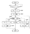
バスリセットの後、各ノードは新しいネットワーク構成を構築するために、各ノードにIDを与える動作に入る。このときの、バスリセットからノードID決定までの一般的なシーケンスを図7から図9に示すフローチャートを用いて説明する。図7は、バスリセット信号の発生から、ノードIDが決定し、データ転送が行えるようになるまでの一連のシーケンス例を示すフローチャートである。各ノードは、ステップS101でバスリセット信号の発生を常時監視し、バスリセット信号が発生するとステップS102に移り、ネットワーク構成がリセットされた状態において新たなネットワーク構成を得るために、互いに直結されているノード間で親子関係が宣言される。そしてステップS103の判定により、すべてのノード間で親子関係が決ったと判定されるまでステップS102が繰り返される。
【0036】
親子関係が決定するとステップS104へ進みルート(root)ノードが決定され、ステップS105で各ノードにIDを与えるノードIDの設定作業が行われる。ルートノードから所定のノード順にノードIDの設定が行われ、ステップS106の判定により、すべてのノードにIDが与えられたと判定されるまでステップS105が繰り返される。
【0037】
ノードIDの設定が終了すると、新しいネットワーク構成がすべてのノードにおいて認識されたことになるのでノード間のデータ転送が行える状態になり、ステップS107でデータ転送が開始されるとともに、シーケンスはステップS101へ戻り、再びバスリセット信号の発生が監視される。
【0038】
図8はバスリセット信号の監視(S101)からルートノードの決定(S104)までの詳細例を示すフローチャート、図9はノードID設定(S105,S106)の詳細例を示すフローチャートである。
【0039】
図8において、ステップS201でバスリセット信号の発生が監視され、バスリセット信号が発生すると、ネットワーク構成は一旦リセットされる。次に、ステップS202で、リセットされたネットワーク構成を再認識する作業の第一歩として、各機器はフラグFLをリーフノードであることを示すデータでリセットする。そして、ステップS203で、各機器はポート数、つまり自分に接続されている他ノードの数を調べ、ステップS204で、ステップS203の結果に応じて、これから親子関係の宣言を始めるために、未定義(親子関係が決定されていない)ポートの数を調べる。ここで、未定義ポート数は、バスリセットの直後はポート数に等しいが、親子関係が決定されて行くにしたがって、ステップS204で検知される未定義ポートの数は減少する。
【0040】
バスリセットの直後に親子関係の宣言を行えるのは実際のリーフノードに限られている。リーフノードであるか否かはステップS203のポート数の確認結果から知ることができ、つまりポート数が「1」であればリーフノードである。リーフノードは、ステップS205で、接続相手のノードに対して親子関係の宣言「自分は子、相手は親」を行い動作を終了する。
【0041】
一方、ステップS203でポート数が「2以上」であったノード、つまりブランチノードは、バスリセットの直後は「未定義ポート数>1」であるからステップS206へ進み、フラグFLにブランチノードを示すデータをセットし、ステップS207で他ノードから親子関係が宣言されるのを待つ。他ノードから親子関係が宣言され、それを受けたブランチノードはステップS204に戻り、未定義ポート数を確認するが、もし未定義ポート数が「1」になっていれば残るポートに接続された他ノードに対して、ステップS205で「自分は子、相手は親」の親子関係を宣言することができる。また、未だ未定義ポート数が「2以上」あるブランチノードは、ステップS207で再び他ノードから親子関係が宣言されるのを待つことになる。
【0042】
何れか一つのブランチノード(または例外的に、子宣言を行えるのにもかかわらず、すばやく動作しなかったリーフノード)の未定義ポート数が「0」になると、ネットワーク全体の親子関係の宣言が終了したことになり、未定義ポート数が「0」になった唯一のノード、つまりすべてノードの親に決まったノードは、ステップS208でフラグFLにルートノードを示すデータをセットし、ステップS209でルートノードとして認識される。
【0043】
このようにして、バスリセットから、ネットワーク内のすべてのノード間における親子関係の宣言までの手順が終了する。
【0044】
次に、各ノードにIDを与える手順を説明するが、最初にIDの設定を行うことができるのはリーフノードである。そして、リーフ→ブランチ→ルートの順に若い番号(ノード番号: 0)からIDを設定する。
【0045】
図9のステップS301で、フラグFLに設定されたデータを基にノードの種類、つまりリーフ、ブランチおよびルートに応じた処理に分岐する。
【0046】
まずリーフノードの場合は、ステップS302でネットワーク内に存在するリーフノードの数(自然数)を変数Nに設定した後、ステップS303で各リーフノードがルートノードに対して、ノード番号を要求する。この要求が複数ある場合、ルートノードはステップS304でアービトレーションを行い、ステップS305である一つのノードにノード番号を与え、他のノードにはノード番号の取得失敗を示す結果を通知する。
【0047】
ステップS306の判断により、ノード番号を取得できなかったリーフノードは、再びステップS303でノード番号の要求を繰り返す。一方、ノード番号を取得できたリーフノードは、ステップS307で、取得したノード番号を含むID情報をブロードキャストすることで全ノードに通知する。ID情報のブロードキャストが終わるとステップS308で、リーフ数を表す変数Nがデクリメントされる。そして、ステップS309の判定により変数Nが「0」になるまでステップS303からS308の手順が繰り返され、すべてのリーフノードのID情報がブロードキャストされた後、ステップS310へ進んで、ブランチノードのID設定に移る。
【0048】
ブランチノードのID設定もリーフノードとほぼ同様に行われる。まず、ステップS310でネットワーク内に存在するブランチノードの数(自然数)を変数Mに設定した後、ステップS311で各ブランチノードがルートノードに対して、ノード番号を要求する。この要求に対してルートノードは、ステップS312でアービトレーションを行い、ステップS313である一つのブランチノードにリーフノードに続く若い番号を与え、ノード番号を取得できなかったブランチノードには取得失敗を示す結果を通知する。
【0049】
ステップS314の判定により、ノード番号の取得に失敗したことを知ったブランチノードは、再びステップS311でノード番号の要求を繰り返す。一方、ノード番号を取得できたブランチノードはステップS315で、取得したノード番号を含むID情報をブロードキャストすることで全ノードに通知する。ID情報のブロードキャストが終わるとステップS316で、ブランチ数を表す変数Mがデクリメントされる。そして、ステップS317の判定により、変数Mが「0」になるまでステップS311からS316の手順が繰返され、すべてのブランチノードのID情報がブロードキャストされた後、ステップS318へ進んで、ルートノードのID設定に移る。
【0050】
ここまで終了すると、最終的にIDを取得していないノードはルートノードのみなので、ステップS318では、他のノードに与えていない最も若い番号を自分のノード番号に設定し、ステップS319でルートノードのID情報をブロードキャストする。
【0051】
以上で、すべてのノードのIDが設定されるまでの手順が終了する。次に、図10に示すネットワーク例を用いてノードID決定のシーケンスの具体的な手順を説明する。
【0052】
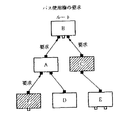
図10に示すネットワークは、ルートであるノードBの下位にはノードAとノードCが直結され、ノードCの下位にはノードDが直結され、ノードDの下位にはノードEとノードFが直結された階層構造を有する。この、階層構造やルートノード、ノードIDを決定する手順は以下のようになる。
【0053】
バスリセットが発生した後、各ノードの接続状況を認識するために、各ノードの直結されているポート間において、親子関係の宣言がなされる。ここでいう親子とは、階層構造の上位が「親」、下位が「子」という意味である。図10では、バスリセットの後、最初に親子関係を宣言したのはノードAである。前述したように、一つのポートだけが接続されたノード(リーフ)から親子関係の宣言を開始することができる。これは、ポート数が「1」であればネットワークツリーの末端、つまりリーフノードであることが認識され、それらリーフノードの中で最も早く動作を行ったノードから親子関係が決定されて行くことになる。こうして親子関係の宣言を行ったノードのポートが、互いに接続された二つのノードの「子」と設定され、相手ノードのノードが「親」と設定される。こうして、ノードA-B間、ノードE-D間、ノードF-D間で「子-親」の関係が設定される。
【0054】
さらに、階層が一つ上がって、複数のポートをもつノード、つまりブランチノードのうち他ノードから親子関係の宣言を受けたノードから順次、上位のノードに対して親子関係を宣言する。図10ではまずノードD-E間、D-F間の親子関係が決定された後、ノードDがノードCに対して親子関係を宣言し、その結果、ノードD-C間で「子-親」の関係が設定される。ノードDから親子関係の宣言を受けたノードCは、もう一つのポートに接続されているノードBに対して親子関係を宣言し、これによってノードC-B間で「子-親」の関係が設定される。
【0055】
このようにして、図10に示すような階層構造が構成され、最終的に接続されているすべてのポートにおいて親となったノードBが、ルートノードと決定される。なお、ルートノードは一つのネットワーク構成中に一つしか存在しない。また、ノードAから親子関係を宣言されたノードBが、速やかに、他のノードに対して親子関係を宣言した場合は、例えばノードCなどの他のノードがルートノードになる可能性もあり得る。すなわち、親子関係の宣言が伝達されるタイミングによっては、どのノードもルートノードになる可能性があり、ネットワーク構成が同一であっても、特定のノードがルートノードになるとは限らない。
【0056】
ルートノードが決定されると、各ノードIDの決定モードに入る。すべてのノードは、決定した自分のID情報を、他のすべてのノードに通知するプロードキャスト機能をもっている。なお、ID情報は、ノード番号、接続されている位置の情報、もっているポートの数、接続のあるポートの数、各ポートの親子関係の情報などを含むID情報としてブロードキャストされる。
【0057】
ノード番号の割当ては、前述したようにリーフノードから開始され、順に、ノード番号=0,1,2,…が割当てられる。そしてID情報のブロードキャストによって、そのノード番号は割当て済みであることが認識される。
【0058】
すべてのリーフノードがノード番号を取得し終わると、次はブランチノードへ移りリーフノードに続くノード番号が割当てられる。リーフノードと同様に、ノード番号が割当てられたブランチノードから順にID情報がブロードキャストされ、最後にルートノードが自己のID情報をブロードキャストする。従って、ルートノードは常に最大のノード番号を所有することになる。
【0059】
以上のようにして、階層構造全体のID設定が終わり、ネットワーク構成が構築され、バスの初期化作業が完了する。
[ノード管理のための制御情報]
ノード管理を行うためのCSRアーキテクチャの基本的な機能として、図4に示したCSRコアがレジスタ上に存在する。それらレジスタの位置と機能を図11に示すが、図中のオフセットは0xFFFFF0000000からの相対位置である。
【0060】
CSRアーキテクチャでは、0xFFFFF0000200からシリアルバスに関するレジスタが配置されている。それらのレジスタの位置と機能を図12に示す。
【0061】
また、0xFFFFF0000800から始まる場所には、シリアルバスのノード資源に関する情報が配置されている。それらのレジスタの位置と機能を図13に示す。
【0062】
CSRアーキテクチャでは、各ノードの機能を表すためコンフィグレーションROMをもっているが、このROMには最小形式と一般形式があり、0xFFFFF0000400から配置される。最小形式では図14に示すようにベンダIDを表すだけであり、このベンダIDは24ビットで表される全世界で固有の値である。
【0063】
また、一般形式は図15に示すような形式で、ノードに関する情報をもっているが、この場合、ベンダIDはルートディレクトリ(root_directory)にもつことができる。また、バス情報ブロック(bus info block)とルートリーフ(root leaf)にはベンダIDを含む64ビットの全世界で固有な装置番号をもっている。この装置番号は、バスリセットなどの再構成後に継続してノードを認識するために使用される。
[シリアルバス管理]
1394シリアルバスのプロトコルは、図3に示したように、フィジカルレイヤ811、リンクレイヤ812およびトランザクションレイヤ814から構成されている。この中で、バス管理は、CSRアーキテクチャに基づくノードの制御とバス資源管理のための基本的な機能を提供している。
【0064】
バス管理を行うノード(以下「バス管理ノード」と呼ぶ)は、同一バス上に唯一存在し、シリアルバス上の他のノードに管理機能を提供するが、この管理機能にはサイクルマスタの制御や、性能の最適化、電源管理、伝送速度管理、構成管理などがある。
【0065】
バス管理機能は、バスマネージャ、同期(アイソクロノス)リソースマネージャおよびノード制御の三つの機能に大きく別けられる。ノード制御は、CSRによってフィジカルレイヤ811、リンクレイヤ812、トランザクションレイヤ814およびアプリケーションにおけるノード間通信を可能にする管理機能である。同期リソースマネージャは、シリアルバス上で同期型のデータ転送を行うために必要になる管理機能で、同期データの転送帯域幅とチャネル番号の割当てを管理するものである。この管理を行うためにバス管理ノードは、バスの初期化後に、同期リソースマネージャ機能をもつノードの中から動的に選出される。
【0066】
また、バス上にバス管理ノードが存在しない構成では、電源管理やサイクルマスタの制御のようなバス管理の一部の機能を同期リソースマネージャ機能をもつノードが行う。さらにバス管理は、アプリケーションに対してバス制御のインタフェイスを提供するサービスを行う管理機能であり、その制御インタフェイスにはシリアルバス制御要求(SB_コントロール.request)、シリアルバスイベント制御確認(SB_コントロール.confirmation)、シリアルバスイベント通知(SB_EVENT.indication)がある。
【0067】
シリアルバス制御要求は、バスのリセット、バスの初期化、バスの状態情報などを、アプリケーションからバス管理ノードに要求する場合に利用される。シリアルバスイベント制御確認は、シリアルバス制御要求の結果で、バス管理ノードからアプリケーションに確認通知される。シリアルバスイベント通知は、バス管理ノードからアプリケーションに対して、非同期に発生されるイベントを通知するためのものである。
[データ転送プロトコル]
1394シリアルバスのデータ転送は、周期的に送信する必要のある同期データ(同期パケット)と、任意タイミングのデータ送受信が許容される非同期データ(非同期パケット)とが同時に存在し、なおかつ、同期データのリアルタイム性を保証している。データ転送では、転送に先立ってバス使用権を要求し、バスの使用許可を得るためのバスアービトレーションが行われる。
【0068】
非同期転送においては、送信ノードIDおよび受信ノードIDが転送データと一緒にパケットデータとして送られる。受信ノードは、自分のノードIDを確認してパケットを受取るとアクノリッジ信号を送信ノードに返すことで、一つのトランザクショが完了する。
【0069】
同期転送においては、送信ノードが伝送速度とともに同期チャネルを要求し、チャネルIDが転送データと一緒にパケットデータとして送られる。受信ノードは、所望するチャネルIDを確認してデータパケットを受取る。必要になるチャネル数と伝送速度はアプリケーションレイヤ816で決定される。
【0070】
これらのデータ転送プロトコルは、フィジカルレイヤ811、リンクレイヤ812およびトランザクションレイヤ814の三つのレイヤによって定義される。フィジカルレイヤ811は、バスとの物理的・電気的インタフェイス、ノード接続の自動認識、ノード間のバス使用権のバスアービトレーションなどを行う。リンクレイヤ812は、アドレッシング、データチェック、パケット送受信、そして同期転送のためのサイクル制御を行う。トランザクションレイヤ814は、非同期データに関する処理を行う。以下、各レイヤにおける処理について説明する。
[フィジカルレイヤ]
次に、フィジカルレイヤ811におけるバスアービトレーションを説明する。
【0071】
1394シリアルバスは、データ転送に先立って、必ず、バス使用権のアービトレーションを行う。1394シリアルバスに接続された各機器は、ネットワーク上を転送される信号をそれぞれ中継することによって、ネットワーク内のすべての機器に同信号を伝える論理的なバス型ネットワークを構成するので、パケットの衝突を防ぐ意味でバスアービトレーションが必要である。これによって、ある時間には、一つのノードだけが転送を行うことができる。
【0072】
図16はバス使用権の要求を説明する図、図17はバス使用の許可を説明する図である。バスアービトレーションが始まると、一つもしくは複数のノードが親ノードに向かって、それぞれバスの使用権を要求する。図16においては、ノードCとノードFがバス使用権を要求している。この要求を受けた親ノード(図16ではノードA)は、さらに親ノードに向かって、バスの使用権を要求することで、ノードFによるバスの使用権の要求を中継する。この要求は最終的に、アービトレーションを行うルートノードに届けられる。
【0073】
バスの使用権の要求を受けたルートノードは、どのノードにバスの使用権を与えるかを決める。このアービトレーション作業はルートノードのみが行えるものであり、アービトレーションに勝ったノードにはバスの使用許可が与えるられる。図17は、ノードCにバスの使用許可が与えられ、ノードFのバスの使用権の要求は拒否された状態を示している。
【0074】
ルートノードは、バスアービトレーションに負けたノードに対してはDP(data prefix)パケットを送り、そのバスの使用権の要求が拒否されたことを知らせる。バスアービトレーションに負けたノードのバスの使用権の要求は、次回のバスアービトレーションまで待たされることになる。
【0075】
以上のようにして、アービトレーションに勝ってバス使用の許可を得たノードは、以降、データ転送を開始することができる。ここで、バスアービトレーションの一連の流れを図18に示すフローチャートにより説明する。
【0076】
ノードがデータ転送を開始できるためには、バスがアイドル状態であることが必要である。先に開始されたデータ転送が終了し、現在、バスがアイドル状態にあることを確認するためには、各転送モードで個別に設定されている所定のアイドル時間ギャップ長(例えば、サブアクションギャップ)の経過を検出し、所定のギャップ長が検出された場合、各ノードはバスがアイドル状態になったと判断する。各ノードは、ステップS401で、非同期データ、同期データなどそれぞれ転送するデータに応じた所定のギャップ長が検出されたか否かを判断する。所定のギャップ長が検出されない限り、転送を開始するために必要なバス使用権を要求することはできない。
【0077】
各ノードは、ステップS401で所定のギャップ長が検出されると、ステップS402で転送すべきデータがあるか判断し、ある場合はステップS403でバスの使用権を要求する信号をルートに対して発信する。このバスの使用権の要求を表す信号は、図16に示すように、ネットワーク内の各機器に中継されながら、最終的にルートノードに届けられる。ステップS402で転送するデータがないと判断した場合は、ステップS401に戻る。
【0078】
ルートノードは、ステップS404でバスの使用権を要求する信号を一つ以上受信したら、ステップS405で使用権を要求したノードの数を調べる。ステップS405の判定により、使用権を要求したノードが一つだったら、そのノードに、直後のバス使用許可が与えられることになる。また、使用権を要求したノードが複数だったら、ステップS406で直後のバス使用許可を与えるノードを一つに絞るアービトレーション作業が行われる。このアービトレーション作業は、毎回同じノードばかりにバスの使用許可を与えるようなことはなく、平等にバスの使用許可を与えるようになっている(フェア・アービトレーション)。
【0079】
ルートノードの処理は、ステップS407で、ステップS406のアービトレーションに勝った一つのノードと、敗れたその他のノードとに応じて分岐する。アービトレーションに勝った一つのノード、またはバスの使用権を要求したノードが一つの場合は、ステップS408でそのノードに対してバスの使用許可を示す許可号が送られる。この許可信号を受信したノードは、直後に転送すべきデータ(パケット)の転送を開始する(ステップS410)。また、アービトレーションに敗れたノードにはステップS409で、バス使用権の要求が拒否されたことを示すDP(data prefix)パケットが送られる。DPパケットを受取ったノードの処理は、再度、バスの使用権を要求するためにステップS401まで戻る。ステップS410におけるデータの転送が完了したノードの処理もステップS401へ戻る。
[トランザクションレイヤ]
トランザクションの種類には、リードトランザクション、ライトトランザクションおよびロックトランザクションの三種類がある。
【0080】
リードトランザクションでは、イニシエータ(要求ノード)がターゲット(レスポンスノード)のメモリの特定アドレスからデータを読取る。ライトトランザクションでは、イニシエータがターゲットのメモリの特定アドレスにデータを書込む。また、ロックトランザクションでは、イニシエータからターゲットに参照データと更新データを転送する。その参照データは、ターゲットのアドレスのデータと組み合わされて、ターゲットの特定のアドレスを指示する指定アドレスになる。そして、この指定アドレスのデータが更新データにより更新される。
【0081】
図19はトランザクションレイヤ814におけるCSRアーキテクチャに基づくリード、ライト、ロックの各コマンドの要求・レスポンスプロトコルを示す図で、図に示す要求、通知、レスポンスおよび確認は、トランザクションレイヤ814でのサービス単位である。
【0082】
トランザクション要求(TR_DATA.request)はレスポンスノードに対するパケットの転送、トランザクション通知(TR_DATA.indication)はレスポンスノードに要求が届いたことの通知、トランザクションレスポンス(TR_DATA.レスポンス)はアクノリッジの送信、トランザクション確認(TR_DATA.confirmation)はアクノリッジの受信である。
[リンクレイヤ]
図20はリンクレイヤ812におけるサービスを示す図で、レスポンスノードに対するパケットの転送を要求するリンク要求(LK_DATA.request)、レスポンスノードにパケット受信を通知するリンク通知(LK_DATA.indication)、レスポンスノードからのアクノリッジ送信のリンクレスポンス(LK_DATA.レスポンス)、要求ノードのアクノリッジ送信のリンク確認(LK_DATA.confirmation)のサービス単位に分けられる。一つのパケット転送プロセスはサブアクションと呼ばれ、非同期サブアクションと同期サブアクションの二つの種類がある。以下では、各サブアクションの動作について説明する。
[非同期サブアクション]
非同期サブアクションは非同期データ転送である。図21は非同期転送における時間的な遷移を示す図である。図21に示す最初のサブアクションギャップは、バスのアイドル状態を示すものである。このアイドル時間が所定値になった時点で、データ転送を希望するノードがバス使用権を要求し、バスアービトレーションが実行される。
【0083】
バスアービトレーションによりバスの使用が許可されると、次に、データがパケット転送され、このデータを受信したノードは、ACKギャップという短いギャップの後、受信確認用返送コードACKを返してレスポンスするか、レスポンスパケットを返送することでデータ転送が完了する。ACKは4ビットの情報と4ビットのチェックサムからなり、成功、ビジー状態またはペンディング状態であることを示す情報を含み、すぐにデータ送信元のノードに返される。
【0084】
図22は非同期転送用パケットのフォーマットを示す図である。パケットには、データ部および誤り訂正用のデータCRCのほかにヘッダ部があり、そのヘッダ部には目的ノードID、ソースノードID、転送データ長や各種コードなどが書込まれている。
【0085】
また、非同期転送は送信ノードから受信ノードへの一対一の通信である。送信元ノードから送り出されたパケットは、ネットワーク中の各ノードに行き渡るが、各ノードは自分宛てのパケット以外は無視するので、宛先に指定されたノードだけがそのパケットを受取ることになる。
[スプリットトランザクション]
トランザクションレイヤ814におけるサービスは、図19で示したトランザクション要求およびトランザクションレスポンスのセットで行われる。ここで、ターゲット(レスポンスノード)のリンクレイヤ812およびトランザクションレイヤ814における処理が充分高速であれば、要求とレスポンスをリンクレイヤ812のそれぞれ独立したサブアクションで処理せず、一つのサブアクションで処理することが可能になる。しかし、ターゲットの処理速度が遅い場合は、要求とレスポンスを個別のトランザクションで処理する必要がある。そして、この動作をスプリットトランザクションと呼ぶ。
【0086】
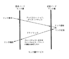
図23はスプリットトランザクションの動作例を示す図で、イニシエータ(要求ノード)のコントローラからのライト要求に対して、ターゲットはペンディングを返す。これにより、ターゲットは、コントローラのライト要求に対する確認情報を返すことができ、データを処理するための時間を稼ぐことができる。そして、データ処理に充分な時間が経過した後、ターゲットは、ライトレスポンスをコントローラに通知してライトトランザクションを終了させる。なお、このときの要求とレスポンスのサブアクションの間には、他のノードによるリンクレイヤ812の操作が可能である。
【0087】
図24はスプリットトランザクションを行う場合の転送状態の時間的遷移例を示す図で、サブアクション1は要求サブアクションを、サブアクション2はレスポンスサブアクションをそれぞれ表している。
【0088】
サブアクション1で、イニシエータはライト要求を表すデータパケットをターゲットに送り、これを受けたターゲットはアクノリッジパケットにより上記の確認情報を示すペンディングを返すことで要求サブアクションが終了する。
【0089】
そして、サブアクションギャップが挿入された後、サブアクション2で、ターゲットはデータパケットが無データであるライトレスポンスを送り、これを受けたイニシエータはアクノリッジパケットでコンプリートレスポンスを返すことでレスポンスサブアクションが終了する。
【0090】
なお、サブアクション1の終了からサブアクション2の開始に至る時間は、最小はサブアクションギャップに相当する時間であり、最大はノードに設定された最大待ち時間まで伸ばすことが可能である。
[同期サブアクション]
1394シリアルバスの最大の特徴であるともいえるこの同期転送は、とくにAVデータなどのリアルタイム転送を必要とするデータの転送に適している。また、非同期転送が一対一の転送であるのに対し、この非同期転送はブロードキャスト機能によって、一つの送信元ノードから他のすべてのノードへ一様にデータを転送することができる。
【0091】
図25は同期転送における時間的な遷移を示す図で、同期転送はバス上で一定時間毎に実行され、この時間間隔を同期サイクルと呼ぶ。同期サイクル時間は125μsである。この同期サイクルの開始を示し、各ノードの動作を同期させる役割を担っているのがサイクルスタートパケット(CSP)2000である。CSP2000を送信するのは、サイクルマスタと呼ばれるノードであり、一つ前のサイクル内の転送が終了し、所定のアイドル期間(サブアクションギャップ2001)を経た後、本サイクルの開始を告げるCSP2000を送信する。つまり、このCSP2000が送信される時間間隔が125μSになる。
【0092】
また、図25にチャネルA、チャネルBおよびチャネルCと示すように、一つの同期サイクル内において複数種のパケットにチャネルIDをそれぞれ与えることにより、それらのパケットを区別して転送することができる。これにより、複数ノード間で、略同時に、リアルタイム転送が可能であり、また、受信ノードは所望するチャネルIDのデータのみを受信すればよい。このチャネルIDは、受信ノードのアドレスなどを表すものではなく、データに対する論理的な番号に過ぎない。従って、送信されたあるパケットは、一つの送信元ノードから他のすべてのノードに行き渡る、つまりブロードキャストされることになる。
【0093】
同期転送によるパケット送信に先立ち、非同期転送と同様に、バスアービトレーションが行われる。しかし、非同期転送のように一対一の通信ではないので、同期転送には受信確認用の返送コードのACKは存在しない。
【0094】
また、図25に示したisoギャップ(同期ギャップ)は、同期転送を行う前にバスがアイドル状態であることを確認するために必要なアイドル期間を表している。この所定のアイドル期間を検出したノードは、バスがアイドル状態にあると判断し、同期転送を行いたい場合はバス使用権を要求するのでバスアービトレーションが行われることになる。
【0095】
図26は同期転送用のパケットフォーマット例を示す図である。各チャネルに分けられた各種のパケットには、それぞれデータ部および誤り訂正用のデータCRCのほかにヘッダ部があり、そのヘッダ部には図27に示すような、転送データ長、チャネル番号、その他各種コードおよび誤り訂正用のヘッダCRCなどが書込まれている。
[バス・サイクル]
実際に、1394シリアルバスにおいては、同期転送と非同期転送が混在できる。図28は同期転送と非同期転送が混在するときの転送状態の時間的遷移を示す図である。
【0096】
ここで、前述したように同期転送は非同期転送より優先して実行される。その理由は、CSPの後、非同期転送を起動するために必要なアイドル期間のギャップ(サブアクションギャップ)よりも短いギャップ(アイソクロナスギャップ)で、同期転送を起動できるからである。従って、非同期転送より同期転送は優先して実行されることになる。
【0097】
図28に示す一般的なバスサイクルにおいて、サイクル#mのスタート時にCSPがサイクルマスタから各ノードに転送される。CSPによって、各ノードの動作が同期され、所定のアイドル期間(同期ギャップ)を待ってから同期転送を行おうとするノードはバスアービトレーションに参加し、パケット転送に入る。図28ではチャネルe、チャネルsおよびチャネルkが順に同期転送されている。
【0098】
このバスアービトレーションからパケット転送までの動作を、与えられているチャネル分繰り返し行った後、サイクル#mにおける同期転送がすべて終了すると、非同期転送を行うことができるようになる。つまり、アイドル時間が、非同期転送が可能なサブアクションギャップに達することによって、非同期転送を行いたいノードはバスアービトレーションに参加する。ただし、非同期転送が行えるのは、同期転送の終了から、次のCSPを転送すべき時間(cycle synch)までの間に、非同期転送を起動するためのサブアクションギャップが検出された場合に限られる。
【0099】
図28に示すサイクル#mでは、三つのチャネル分の同期転送の後、非同期転送によりACKを含む2パケット(パケット1、パケット2)が転送されている。この非同期パケット2の後、サイクルm+1をスタートすべき時間(cycle synch)に至るので、サイクル#mにおける転送はこれで終わる。ただし、非同期または同期転送中に次のCSPを送信すべき時間(cycle synch)に至ったら、転送を無理に中断せず、その転送が終了した後にアイドル期間を経て次の同期サイクルのCSPを送信する。すなわち、一つの同期サイクルが125μs以上続いたときは、その延長分、次の同期サイクルは基準の125μsより短縮される。このように同期サイクルは125μsを基準に超過、短縮し得るものである。
【0100】
しかし、同期転送はリアルタイム転送を維持するために、必要であれば毎サイクル実行され、非同期転送は同期サイクル時間が短縮されたことによって次以降の同期サイクルに延期されることもある。サイクルマスタは、こういった遅延情報も管理する。
【0101】
【データ転送処理】
[データ転送プロトコル]
図29は、1394シリアルバス上におけるデータ転送のためのプロトコルスタックを説明するための図である。
【0102】
アプリケーションは、しばしば画像データといった大量のデータを、デバイス間でやり取りする必要がある。そのような場合に、データ転送に関わるハードウェア技術の細部、制限事項、データのエラー再転送の処理等をアプリケーションプログラムから分離するために、アプリケーションに信頼性のあるデータ転送サービスを提供し、汎用的なインタフェースを定める必要がある。
【0103】
そこで本実施形態においては、アプリケーションプログラムがデータ転送を行なう際に、図29に示すような階層化されたプロトコル体系を用いる。図29は、上から順にアプリケーションレイヤ29-1、セッションレイヤ29-2、トランザクションレイヤ29-3、以下、IEEE1394で定められた1394トランザクションレイヤ29-4、1394フィジカルレイヤ29-5を示す。ここで、1394トランザクションレイヤ29-4が上述した図3に示すトランザクションレイヤ814に、1394フィジカルレイヤ29-5がリンクレイヤ812及びフィジカルレイヤ811に相当する。
【0104】
本実施形態においてデータを送信するデバイスは、以下のような動作をする。まずデータ転送アプリケーション29-1は、画像データ等の大量のデータを、データ転送APIのような抽象化されたインタフェースを用いて下位のセッションレイヤ29-2に渡す。セッションレイヤ29-2は、アプリケーションデータを図30で定義されているブロックレジスタ30-3の単位に分割し、下位のトランザクションレイヤ29-3に順次渡していく。トランザクションレイヤ29-3は、ブロックレジスタ30-3単位のアプリケーションデータを、下位の1394トランザクションレイヤ29-4のライトトランザクションに適した単位に分割し、1394トランザクション29-4のライトトランザクションサービスインタフェースを呼び出す。1394トランザクションレイヤ29-4及び1394フィジカルレイヤ29-5は、IEEE1394で定義された手段で、上記分割されたアプリケーションデータを他のデバイスに転送する。
【0105】
また、データを受信するデバイスは、以下のような動作をする。送信側から転送されてきた適切に分割されたデータは、1394フィジカルレイヤ29-5及び1394トランザクションレイヤ29-4により、トランザクションレイヤ29-3で定義されるデータ受信デバイスのブロックレジスタ30-3に、順次書き込まれる。トランザクションレイヤ29-3は、ブロックレジスタ30-3に順次書き込まれてくるデータを再構成し、1ブロックレジスタ単位のデータに組み立て、上位のセッションレイヤ29-2に渡す。セッションレイヤ29-2は、上記1ブロックレジスタ単位のデータを順次受け取り、データストリームの形に再構成してアプリケーション29-1に渡す。データ受信側アプリケーション29-1は、抽象化されたインタフェースを介して、データ送信側デバイスから画像データ等の大量のデータを受け取る。
[レジスタ構成]
図30は、図29のトランザクションレイヤ29-3がデバイス同士でデータ転送を行うためのレジスタ構成を示した図であり、1394シリアルバスの初期ユニット空間(図4のユニット空間で示される)に配置される。デバイスはデータ転送を行うに先立って、転送相手のレジスタが配置されているアドレス、サイズを予め知っており、データ転送を行うためにこれらのレジスタを使用する。レジスタは実際のデータを書き込むブロックレジスタ30-3と、ブロックレジスタ30-3への書き込み制御(書き込み完了通知)を行うためのコントロールレジスタ30-1と、コントロールレジスタ30-1への書き込み完了通知に対して、書き込まれたデータの正否(ACK/NACK)を返答するためのレスポンスレジスタ30-2から構成される。コントロールレジスタ30-1とレスポンスレジスタ30-2を合わせて、ブロックマネージメントレジスタと呼ぶ。これらのレジスタは、画像データを転送する画像供給デバイスと、画像データを受けて印字を行うプリンタの双方に準備され、相互にデータ転送を行うことが可能である。
【0106】
図31に、図30に示したレジスタを用いたコマンドの転送の概要を示す。これは、画像供給デバイスからプリンタへのコマンド転送の例であり、画像供給デバイスは、プリンタに送るべきコマンドデータをプリンタ側のブロックレジスタ31-6に書き込む(コマンド31-9)。次に、画像供給デバイスはプリンタ側のコントロールレジスタ31-4にコマンドデータの転送終了を通知するための書き込みを行う(コントロール31-7)。プリンタは、正常にデータを受け取れたか否かを画像供給デバイスに返答するために、画像供給デバイスのレスポンスレジスタにACKあるいはNACKに相当する内容を書き込む(レスポンス31-8)。
【0107】
以上の手順で、画像供給デバイスからプリンタのレジスタへの、コマンドの書き込みと、該書き込みに対する返答が行われる。プリンタからACKの返答が画像供給デバイスのレスポンスレジスタに書き込まれれば、コマンドは正常にプリンタに受け取られたことを示し、NACKが戻された場合には、何らかの理由でデータが正しくプリンタへ送られていないことを示す。返答がNACKである場合には、画像供給デバイスはエラーに対する終了処理やコマンドの再転送処理等、何らかのエラー処理を行う必要がある。
【0108】
図32は、図31でレジスタに書き込まれたコマンドに対する返答を、プリンタから画像供給デバイスに戻す場合の手順を示している。プリンタは画像供給デバイスに送るべきリプライ(返答)を画像供給デバイス側のブロックレジスタ32-3に書き込む(リプライ32-9)。次にプリンタは、画像供給デバイス側のコントロールレジスタ32-1にリプライの転送終了を通知するための書き込みを行う(コントロール32-7)。画像供給デバイスは、正常にデータを受け取れたか否かをプリンタに返答するために、画像供給デバイスのレスポンスレジスタ32-5にACKあるいはNACKに相当する内容を書き込む(レスポンス32-8)。
【0109】
以上の手順で、プリンタから画像供給デバイスのレジスタへの、リプライの書き込みと、該書き込みに対する返答が行われる。画像供給デバイスからACKの返答がプリンタのレスポンスレジスタに書き込まれば、リプライは正常に画像供給デバイスに受け取られたことを示し、NACKが戻された場合には、何らかの理由でデータが正しく画像供給デバイスへ送られていないことを示す。返答がNACKである場合には、プリンタはエラーに対する終了処理やコマンドの再転送処理等、何らかのエラー処理を行う必要がある。
【0110】
以上、図31,図32を参照して、画像供給デバイスからプリンタへのコマンド及びそれに対するリプライの転送手順を示した。これらが一般的なコマンドとリプライの手順である。なお、コマンドによってはリプライを必要としないものも考えられ、この場合には図32に示した手順が実行されないことになる。これらはコマンドごとに決める事ができる。
【0111】
図33は、ブロックレジスタ33-1と、装置が内部的に有するバッファとの関係を示した図である。ブロックレジスタ33-1と同じ大きさを持つ複数のバッファBlockbuffer[1]〜[n](33-2〜33-7)が装置内部に用意されており、ブロックレジスタ33-1に対する書き込みが行われると、Blockbuffer[1]〜[n]に保存される。ブロックレジスタ33-1に対する書き込みは、内部バッファに空きがある場合、書き込まれたデータをバッファに保存した後、次に保存ができる空きバッファがある場合に、ACKを画像供給デバイスに返す。バッファに空きがなくなると、最後のバッファに対する保存を行った後、空のバッファができるまでACKは画像供給デバイスに返されない。
【0112】
画像供給デバイスにおいては、プリンタ側にバッファの空きができてACKが戻されるまで、次のコマンドの転送は行えないことになる。プリンタにおいてバッファに空きができるのは、印字を行うデータの場合、例えばBlockbuffer[1]のデータを印字のためのデータに変換し、該バッファ内のデータが全部処理されるとバッファは空になり、再びブロックレジスタ33-1に書き込まれたデータを保存することができるようになる。
【0113】
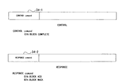
図34は、上部が図30に示したコントロールレジスタ30-1の構成を示しており、コントロールコマンド34-1にその制御内容が設定される。例えば、コントロールコマンド34-1が01hであればBLOCK COMPLETEを表し、すなわちブロックレジスタへの書き込み完了を示す。
【0114】
また、図34の下部が図30に示したレスポンスレジスタ30-2の構成を示しており、レスポンスコマンド34-2にその返答内容が設定される。例えば、レスポンスコマンド34-2が01hであればBLOCK ACKを表し、即ちコントロールレジスタ30-1へBLOCK COMPLETEが書き込まれた後、データが正しく受け取られたことを示し、02hであればBLOCK NACKを表し、即ちコントロールレジスタ30-1へBLOCK COMPLETEが書き込まれた後、データが正しく受け取られなかったことを示す。
【0115】
これらのコントロールコマンドとレスポンスコマンドを用いることにより、ブロックレジスタへのデータの書き込み完了の通知とそれに対する返答を行うことができる。
【0116】
図35は、ブロックレジスタ30-3に書き込まれるコマンドの一般形式を示した図である。コマンドは、その識別子であるCommandID35-1と、コマンドに付随するParameter35-2からなる。
【0117】
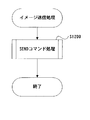
図36は、実際のコマンドの例を示す図である。同図において、左側は画像データを転送するためのコマンド(SENDコマンド)であり、CommandIDをSEND(36-1)とし、Parameterとして、転送する画像データであるImage Data(36-2)を有する。このコマンドにより、画像供給デバイスからプリンタへ印字を行うための画像データの転送を行うことができる。
【0118】
また、図36の右側は画像供給デバイスがプリンタの状態を示すステイタスをプリンタから受け取るためのコマンド(GETSTATUSコマンド)であり、CommandIDをGETSTATUS(36-3)とし、Parameterは有しない。即ち、GETSTATUSコマンドではParameterを必要としない。
【0119】
これらのコマンドが、図31のコマンド31-9として画像供給デバイスからプリンタへ転送される。但し、上記SENDコマンドの場合、画像データはブロックレジスタ30-3の大きさに比べて大きい場合が普通であり、この場合にはブロックレジスタ30-3に合ったサイズでの書き込みを複数回行うことになる。
【0120】
図37は、図36に示したコマンドに対するリプライを示す図である。同図において、左側はSENDコマンドに対するリプライ(SENDリプライ)である。このリプライは、SENDコマンドに対してプリンタから画像供給デバイスにコマンドの実行ステイタスを戻すものであり、SENDリプライ37-1と、コマンドの実行ステイタスを示すSENDリプライステイタス37-2から構成される。
【0121】
また、図37の右側はGETSTATUSコマンドに対するリプライである。このリプライは、GETSTATUSコマンドに対してプリンタから画像供給デバイスにプリンタのステイタスを戻すものである。
【0122】
これらのリプライが、図32のリプライ32-9としてプリンタから画像供給デバイスへ転送される。
【0123】
図36,図37に示したコマンドとリプライにより、図29に示した画像供給デバイスのアプリケーションが、プリンタのアプリケーションに対してイメージデータの転送による印字要求、及びプリンタのステイタス取得を行なうことが可能となる。
【0124】
図38は、図37のGETSTATUSリプライで戻される、プリンタステイタス38-1の詳細を示した図であり、例えば、紙なし、エラー、ビジー等のステイタスを持つことができる。画像供給デバイスはこのステイタスにより、プリンタの現在の状態を知ることができる。例えば、画像供給デバイスにプリンタの用紙切れを知ることができ、この場合には画像供給デバイスのユーザにその旨を報知することもできる。また、プリンタにエラーが発生しているような場合には、印字を行わないように制御することも可能となる。
【0125】
図39は、SENDコマンドにより画像データ39-1を送る際に、ブロックレジスタ31-3に対して画像データ39-1のサイズが大きい場合を示す。この場合、一度には転送できないため、同図に示すように画像データ39-1をブロックレジスタ30-3のサイズに合わせて分割し、複数のコマンド39-2〜39-5として転送する。この処理は、図29に示すセッションレイヤ29-2で行われる。以降、これら分割された一回のコマンド転送を、WriteBlockと称する。従って、大量の画像データを転送する場合、WriteBlockが複数回実行されることになる。尚、画像供給デバイスからプリンタのブロックレジスタ31-6に転送された画像データは、図33に示したように、プリンタ側の内部的なバッファに保存される。
【0126】
そして、セッションレイヤ29-2で制御されてWriteBlockされる画像データはさらに、トランザクションレイヤ29-3において、IEEE1394規格に準拠したデータ転送単位(1934トランザクション39-6〜39-9)に分解される。即ち1394シリアルバス上において、1394トランザクション39-6単位でのデータ転送が複数回行われることにより、ブロックレジスタ31-3の全ての領域への画像データの書込みが遂行される。
[一般的なデータ転送制御]
図40は、Write Blockを繰り返し行なう場合の、画像供給デバイスとプリンタの一般的な制御手順を示す図である。画像供給デバイスはプリンタに対して、分割されたコマンド単位でWriteBlockを行う。具体的には、SENDコマンドが繰り返し転送される。
【0127】
まず、ステップS40-1において、画像供給デバイスは第1番目のコマンドをプリンタのブロックレジスタ31-6に書き込むためのWriteBlockを行なう。そしてブロックレジスタ31-3の分のデータ書き込みが終了すると、ステップS40-2においてWriteBlockの完了を通知するBLOCK COMPLETEをプリンタのコントロールレジスタ31-4に書き込む。
【0128】
これに対して、プリンタはバッファの空きがあり、ブロックレジスタに書き込まれたコマンドが正常であるため、ステップS40-3でBLOCK ACKを画像供給デバイスへのレスポンスレジスタ31-2に書き込む。この場合の、BLOCK COMPLETEの発生からBLOCK ACKが戻されるまでの応答時間をT1で示す。このような、WriteBlockからBLOCK ACKまでの一連の処理(ステップS40-1〜S40-3)により、一つのブロック単位での転送が終了する。以降、ステップS40-4〜S40-6に示されるように、プリンタの空きバッファがなくなるまで、WriteBlockが繰り返される。
【0129】
プリンタは、印字動作に従って送られたデータを消費してバッファを空とし、バッファの再利用を行う。しかし、画像供給デバイスからのデータ転送がプリンタのバッファ消費速度よりも速い場合、空きバッファが無くなるため、ステップS40-7に示すプリンタの最終バッファに対するWriteBlockが行われることになる。これは、画像供給デバイスはプリンタのバッファに対する残り数などの情報を持たないため、BLOCK ACKが戻されれば直ちにWriteBlockを実行するためである。尚、図40は、プリンタ側がn個のバッファを有している場合を示している。
【0130】
ステップS40-7において最終バッファに対してWriteBlockが行われ、更にステップS40-8でBLOCK COMPLETEが転送されると、この転送によってプリンタのバッファが一杯となるため、バッファに空きができるまで、プリンタはBLOCK ACKを画像供給デバイスに転送できなくなる。そのため、通常はBLOCK COMPLETEからBLOCK ACKまでの応答時間はT1で済んでいたのに対し、バッファが空になるまでのT2時間の間、画像供給デバイスはデータ転送ができないことになる。そしてT2が経過してプリンタからBLOCK ACKが戻された後、画像供給デバイスは次のデータを転送することができるようになる。即ち、応答時間がT1よりもはるかに長いT2となってしまう。
【0131】
図41は、本実施形態におけるGETSTATUSコマンドの制御手順を示す図であり、SENDコマンドにより画像データを転送している途中でGETSTATUSコマンドを実行する場合処理の流れを示している。
【0132】
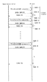
WriteBlockを繰り返し行っている間に、プリンタのステイタスを取る必要がある場合、GETSTATUSコマンドは定期的に実行される。即ち、GETSTAUSコマンドがSENDコマンドの途中で実行される。まずステップS41-1〜41-6までSENDコマンドが実行され、所定時間になると、ステップS41-7でGETSTATUSコマンドが実行される。
【0133】
以下、GETSTATUSコマンド制御について詳細に説明する。まずステップS41-8において、WriteBlockでGETSTATUSコマンドがプリンタのブロックレジスタに書き込まれる。次に、ステップS41-9でBLOCK COMPLETEがプリンタのコントロールレジスタに書き込まれる。これに対して、ステップS41-10でプリンタから画像供給デバイスのレスポンスレジスタにBLOCK ACKが戻され、ステップS41-11でプリンタ側からGETSTATUSリプライが画像供給デバイスのブロックレジスタに書き込まれる。そしてステップS41-12において、プリンタからBLOCK COMPLETEが画像供給デバイスのコントロールレジスタに書き込まれ、ステップS41-13でそれに対するBLOCK ACKがプリンタのレスポンスレジスタに戻される。
【0134】
ステップS41-7に示す一連の処理により、GETSTATUSコマンドがSENDコマンド中に割り込み実行される。そしてGETSTATUSコマンドの実行後、ステップS41-14〜S41-16において、中断されていたSENDコマンドが再開される。即ち、SENDコマンドの間にGETSTATUSコマンドが割り込んで実行され、GETSTATUSコマンドの終了を待って、SENDコマンドが再開される。
【0135】
従って画像供給デバイスは、SENDコマンドの実行中であってもGETSTATUSコマンドによってプリンタの現在のステイタスを得ることができ、プリンタの状況を確認しながらデータ転送を行うことができる。このGETSTATUSコマンドの割り込み処理は、図29に示すアプリケーションレイヤ29-1から指示され、セッションレイヤ29-2で処理される。即ち、画像供給デバイスのアプリケーションがSENDコマンドをセッションレイヤに指示した後、特定の時間ごとに、プリンタのステイタスを得るために、アプリケーションがセッションレイヤに対してGETSTATUSコマンドを発行することを意味している。
【0136】
しかし、図41に示した例においてGETSTAUSコマンドが実行できるのは、プリンタのバッファに空きがある場合に限られる。例えば、図40のステップS40-8〜S40-9に示した、WriteBlockが行なえない応答時間T2の間に、GETSTATUSコマンドを実行する時間になってしまった場合には、GETSTATUSコマンドが転送できないという不都合が生じる。これは上述したように、プリンタ側に空きバッファが無いためであり、この応答時間T2が長ければ、一定の時間毎にプリンタのステイタスを得ることができなくなってしまう。このように、プリンタ側におけるバッファの残り数によっては、プリンタステイタスが定期的に得られないという問題が生じてしまうことがある。
【0137】
【本実施形態におけるデータ転送処理】
[ダミー処理概要]
本実施形態は、上述した図29〜図41を参照して説明した一般的なコマンド転送における問題を解決する。以下、この解決方法について詳細に説明する。尚、以下の説明は、上述した図34,図40を適当に変更したものであり、図29〜図41の他の図については同様である。
【0138】
本実施形態においては、上述した図34で示したコントロールレジスタ30-1及びレスポンスレジスタ30-3の構成を、図42に示すように変更したことを特徴とする。図42の下部はレスポンスレジスタ30-3の構成を示すが、BLOCK count42-3が追加されていることを特徴とする。BLOCK count42-3は、プリンタ側が持つ空きバッファの数を設定する部分であり、従って本実施形態においては、プリンタはWriteBlockに対するACK/NACKの他に、BLOCK countを画像供給デバイスに戻すことができる。
【0139】
図43は、上述した図36で示したSENDコマンド及びGETSTATUSコマンドの他に、本実施形態で追加されるDUMMYBLOCKコマンド(以下、単にDUMMYコマンドと称する)を示す。これは画像供給デバイスからプリンタに送られるコマンドであり、画像供給デバイスはプリンタから戻されるレスポンスにおいてBLOCK count42-3で示される空きブロック数が予め定められた数よりも少なくなった場合に、SENDのコマンドに代わってプリンタに送り出される。プリンタ側は、このDUMMYコマンドを受け取ると、内部のブロックバッファ33-2〜33-7に保存を行わず、かつ空きバッファの数を変えずに、BLOCK ACK,NACKを画像供給デバイスのレスポンスレジスタ31-2に戻す。このように、DUMMYコマンドは対応するリプライを持たないコマンドである。尚、DUMMYコマンド処理の詳細について後述する。
[DUMMYコマンド制御手順]
本実施形態においては、上述した図40に示したWriteBlockのリピート処理を、図44に示すように変更したことを特徴とし、その差異は以下の点にある。まず、図40のステップS40-3等で示したBLOCK ACK返答に対して、図44のステップS44-3のBLOCK ACK返答においては残りバッファ数を示すBLOCK count42-3がセットされている点である。そして更に、図40では、ステップS40-7で示した最終バッファへのWriteBlockとステップS40-9でBLOCK ACKが戻されるまでの応答時間T2は転送待ちの状態となるのに対して、図44では、ステップS44-9でBLOCK countが1としてBLOCK ACKが戻された場合、BLOCK countがm(mは1以外の値)でBLOCK ACKが戻されるまで、ステップS44-10のダミー処理を行う点である。
【0140】
以下、本実施形態におけるダミー処理について説明する。まずステップS44-11において、画像供給デバイスがBLOCK ACKのBLOCK countが1となったことを判断して、SENDコマンドに代えてDUMMYコマンドをプリンタのブロックレジスタに書き込む。そしてステップS44-12においてWriteBlockの完了を通知するBLOCK COMPLETEをプリンタのコントロールレジスタに書き込む。するとステップS44-13で画像供給デバイスのレスポンスレジスタにBLOCK ACKが戻されるが、このBLOCK ACKにセットされたBLOCK countが1である限り、ステップS44-13〜S44-14に示すように、プリンタのブロックレジスタへのDUMMYコマンドの書き込みを継続する。
【0141】
尚、プリンタ側においては、ブロックレジスタにDUMMYコマンドが書き込まれるとDUMMYコマンドであることを判定し、該DUMMYコマンドをバッファに保存せずにBLOCK ACKを戻す。従って、返答する時点の空きバッファの数がBLOCK countとして戻されるため、空きバッファが増えていればBLOCK countは増え、空きバッファが増えていなければ引き続きBLOCK countに1をセットしてBLOCK ACKを戻す。
【0142】
画像供給デバイスにおいては、ステップS44-16でBLOCK ACKのBLOCK countに1以外の数がセットされて戻されると、ステップS44-17〜S44-22において、ダミー処理で中断されていたSENDコマンドの転送処理を再開する。
【0143】
以上、図44において示したように本実施形態においては、プリンタ側のバッファが空くまでダミー処理を行うことができる。従って、プリンタ側のバッファに空きがない状態であっても、以下に示すようにGETSTATUSコマンドを実行することができる。
[DUMMY,GETSTATUSコマンド制御手順]
以下、図45に本実施形態におけるDUMMYコマンド及びGETSTATUSコマンドの制御手順を示す。上述したように、図44のステップS44-9においてBLOCK countが1となった場合に、本実施形態のダミー処理が実行される。図45においては、ステップS45-5がダミー処理を、ステップS45-8がダミー処理中におけるGETSTATUSコマンド実行処理を示す。以下、ステップS45-8におけるダミー処理中のGETSTATUSコマンド実行処理について詳細に説明する。
【0144】
ステップS45-5に示すダミー処理の間に、画像供給デバイスがプリンタのステイタスを取り込むべき時期となった場合、画像供給デバイスはプリンタのブロックレジスタに書き込んでいたDUMMYコマンドに代えて、GETSTATUSコマンドの書き込み(ステップS45-9)を行う。尚、GETSTATUSコマンドの実行処理は、上述した図41と同様であるため、説明を省略する。
【0145】
そしてステップS45-11において、GETSTATUSコマンドに対して戻されたBLOCK ACKにセットされたBLOCK countが依然として1であれば、GETSTATUSコマンド処理の実行後も、ステップS45-15〜S45-17に示すように、BLOCK countが1以外になるまでDUMMYコマンド処理が実行される。
【0146】
ステップS45-17においてBLOCK countが1以外の数が戻されると、ステップS45-18以降、上述した図44において説明したのと同様に、SENDコマンドの処理が再開される。
【0147】
以上、図44,図45を参照して説明したように本実施形態においては、まずプリンタ側のバッファの残り数を知ることができ、その残り数が1となった場合にダミー処理が実行される。ダミー処理中、プリンタ側ではDUMMYコマンドがバッファに保存されることが無いため、残りバッファ数が減ることは無い。従って、ダミー処理中にGETSTATUSコマンド等の他のコマンドをブロックレジスタに書き込むことができる。即ち、図40に示す例においては、空きバッファがない間、即ち応答時間T2の間は、GETSTATUSコマンドを割り込んで発行することができなかったが、本実施形態ではDUMMYコマンドを設けたことにより、空きバッファがなくてもGETSTATUSコマンドを割り込み発行することができる。尚、この際の画像供給デバイス、プリンタの各処理の詳細については、後述する。
[SEND前のDUMMYコマンド制御手順]
図46は、本実施形態におけるSENDコマンド前のDUMMYコマンドの制御手順を示す図であり、即ち、一番最初のSENDコマンドを実行する前にDUMMYコマンドを送る場合の手順を示す。
【0148】
図46において、ステップS46-4が最初のSENDコマンドであり、それに先立ってステップS46-1〜S46-3においてDUMMY処理が行われる。このように、まずDUMMYコマンド処理を最初に行うことにより、バッファがまだSENDコマンドによって使用されていない状態であるため、ステップS46-3で戻されるBLOCK countnがプリンタの持つバッファの総数を示すため、SENDコマンドを開始する前に、プリンタが持つバッファの総数を知ることができる。即ち、バッファの使用を開始するのに先立って、バッファの総数を知ることが可能となる。
【0149】
例えばプリンタがバッファを1つしか持たない場合にダミー処理を実行すると、SENDコマンドがいつまでも実行されず、DUMMYコマンドが無限に繰り返されてしまうことが考えられる。従って、図46に示すように、SENDコマンドに先立ってDUMMYコマンドを実行することで、プリンタのバッファ数が1である場合にはダミー処理を行わないように制御することができる。
[トラフィック効率化]
図47は、上述した図44でも説明した、DUMMYコマンドの制御手順を示す図であり、BLOCK COMPLETEに対するBLOCK ACKの応答時間がT1であることを示す。このように、画像供給デバイスはBLOCK ACKがBLOCK countが1にセットされて戻る限りにおいて、プリンタ側のブロックレジスタへのDUMMYコマンドの書き込みを繰り返す。
【0150】
ここで、応答時間T1が短いとダミー処理が数多く実行されることになり、バス上のトラフィックを無駄に増加させることになる。これを画像供給デバイス側において解決するには、BLCOK ACK後、次のDUMMYコマンドをブロックレジスタに書き込むまでにタイマによって時間計測を行い、ブロックレジスタにDUMMYコマンドが書き込まれる回数を調整する方法が考えられる。しかし、この方法では画像供給デバイスの処理が増え、複雑になってしまう。
【0151】
そこで本実施形態においては以下に示す方法により、1394シリアルバス上のトラフィックの効率化を実現する。
【0152】
図48は、本実施形態においてトラフィックの増加を抑制するためのDUMMYコマンド制御手順を示す図である。図48においては、プリンタがBLOCK COMPLETEに対してBLOCK ACKを戻すまで(ステップS48-2〜S48-3等)の応答時間を、T1よりも長いT1'に調整することを特徴とする。これにより、画像供給デバイス側ではBLOCK ACKが戻ればすぐにDUMMYコマンドをプリンタのブロックレジスタへ書き込むことができる。
【0153】
また、応答時間T1’をプリンタ側で制御できるため、印字速度やバッファの消費速度等、プリンタ側の条件を考慮してT1'を調整することができる。
このように本実施形態においては、プリンタ側で応答時間をT1'に調整するだけで、画像供給デバイス側に処理を追加することなく、1394シリアルバス上のトラフィックの効率化を実現することができる。
【0154】
以下、本実施形態におけるデータ転送処理に関し、画像供給デバイス側及びプリンタ側のそれぞれについて詳細に説明する。
[画像供給デバイスにおける画像転送処理]
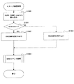
図49は、本実施形態の画像供給デバイスにおける画像転送処理を示すフローチャートである。ここで画像転送処理は、画像供給デバイスがプリンタに対して画像データを転送しプリンタで印字を行う処理であり、まずステップS500において、DUMMYコマンド書込み処理を行う。これは上述した図46において説明したように、相手のバッファの数を確認するための処理である。次にステップS501において、ステップS500で戻されたBLOCK countが1であるか否かを判定し、1であればステップS502へ進んでENADUMMYSENDflagを0にセットする。ここでENADUMMYSENDflagは、DUMMY処理を行うか否かを判定するためのフラグであり、0ならばダミー処理は行わず、1であればダミー処理を行うことを示す。ステップS501においてBLOCK countが1でなければ、ステップS503へ進んでENADUMMYSENDflagを1にセットする。そしてステップS504に進み、後述するSENDコマンド処理を実行する。
【0155】
図50は、上記ステップS504における画像供給デバイスのSENDコマンド処理の詳細を示すフローチャートである。まずステップS600において、SNEDコマンド処理中にGETSTATUSコマンドの要求があったか否かの判定を行う。本実施形態においては、タイマ処理により一定時間ごとにGETSTATUSコマンドの割り込みがかかり、GETSTATUSコマンド要求が設定される。このGETSTATUSコマンドの割り込みの詳細については後述する。ステップS600でGETSTATUSコマンド要求があれば、ステップS601へ進んでGETSTAUSコマンド処理を実行する。これは上述した図38で説明したプリンタのステイタスを取り出す処理であり、SNEDコマンド実行中にプリンタにエラーや異常がないかを確認するために利用される。
【0156】
ステップS601のGETSTATUSコマンド処理が終了すると、処理はステップS600にもどる。ステップS600でGETSTATUSコマンド要求がなければ、ステップS602へ進んでBLOCK countが1であるかをチェックする。BLOCK countが1であれば、プリンタの持つ空きバッファが残り1つであることを示しており、ステップS603へ進んでENADUMMYflagが1であるかをチェックする。ENADUMMYBLOCKflagはDUMMYコマンド処理が実行可能であるか否かを示すフラグであり、上述した図49のステップS502,S503において、プリンタ側の持つ空きバッファの総数に応じてその設定がなされる。ステップS603でENADUMMYBLOCKflagが1でなければ、DUMMYコマンド処理は行わずにステップS600へ戻る。この処理は、本実施形態において図46に示した、プリンタ側のバッファの総数が1である場合にDUMMYコマンド処理を行わないようにする処理に相当する。ステップS603でENADUMMYBLOCKflagが1であれば、ステップS604へ進んで、上述した図45においてステップS45-4で示したDUMMYコマンドの転送処理を実行する。即ち、プリンタ側のバッファ総数が1以上でBLOCK countが1となった(プリンタの残り空きバッファが1となった)場合に、DUMMYコマンドの転送処理を行う。そして次にステップS606へ進む。
【0157】
一方、ステップS602においてBLOCK countが1でなければステップS605へ進み、SENDコマンドの転送処理を実行する。これは、上述した図45においてステップS45-1,S45-18,S45-21に相当し、プリンタへ画像データを送る処理である。ここで、画像データが1つのバッファに収まらないような場合、上述した図39で示したように、該イメージデータは複数のSNEDコマンドに分割されてプリンタのブロックレジスタに書き込まれる。ステップS605は分割された画像データの1つを書き込む処理に相当し、ステップS605が繰り返し実行されることにより、画像データ全体が転送される。
【0158】
次にステップS606へ進み、プリンタ側のコントロールレジスタにBLOCK COMPLETEを書き込む。このBLOCK COMPLETEの書き込みにより、ブロックレジスタへのデータ書き込みの終了がプリンタ側に通知される。
【0159】
次にステップS607へ進み、タイムアウトかどうかをチェックする。即ち、ステップS606でプリンタのコントロールレジスタにBLOCK COMPLETEを書き込んでから、画像供給デバイスのレスポンスレジスタにBLOCK ACK/NACKが戻されるまでの時間をタイマにより計測し、所定時間が経過してもBLOCK ACK/NACKが戻されない場合に、タイムアウトとなる。ステップS607でタイムアウトととなった場合、ステップS608へ進みタイムアウト処理を行なう。ここでタイムアウト処理は、ユーザに何らかの理由でタイムアウトが発生し、プリンタへのデータ送信がうまくいかなかったことを報知したり、プリンタへのデータ転送処理を終了する処理である。タイムアウト処理後、SENDコマンド処理は終了する。
【0160】
ステップS607においてタイムアウトでない場合、ステップS609へ進んでプリンタから画像供給デバイスのレスポンスレジスタにBLOCK NACKが戻されたか否かをチェックする。BLOCK NACKが戻された場合、プリンタへ送ったデータに何らかの不具合があったため、ステップS610のNACK処理へ進む。ステップS610のNACK処理は、タイムアウト処理と同様に何らかの理由でプリンタへのデータ送信がうまくいかなかったため、プリンタへのデータ転送処理を終了することを行う。NACK処理後、SENDコマンド処理は終了する。
【0161】
ステップS609においてBLOCK NACKでない場合、ステップS611へ進んでプリンタからBLOCK ACKが戻されたか否かをチェックし、BLOCK ACKでなければステップS607へ戻る。BLOCK ACKならばステップS612へ進み、SNEDコマンドが終了したか否かをチェックする。終了でなければステップS600へ戻り、上述した処理を繰り返す。一方、ステップS612でSENDコマンドが終了していれば、SENDコマンド処理は終了となる。
【0162】
以上、図50を参照して説明したように、本実施形態の画像供給デバイスにおいては、SNED,DUMMYコマンドの実行とSENDコマンド実行中のGETSTATUSコマンドの処理が行えることが分かる。これは、上述した図45で説明したDUMMY,GETSTATUSコマンド制御手順において画像供給デバイス側の手順に相当する処理である。
【0163】
図51は、上述した図50のステップS601に示したGETSTATUSコマンド処理の詳細を示すフローチャートであり、即ち、画像供給デバイスが、プリンタからステイタスを受け取るためのコマンドをプリンタ側のブロックレジスタに書き込む処理である。まずステップS700において、GETSTATUSコマンドをプリンタ側のブロックレジスタに書き込む。これは、上述した図45のステップS45-9に相当する。次にステップS701へ進み、プリンタのコントロールレジスタにBLOCK COMPLETEを書き込む。これは、図45のステップS45-10に相当する。次にステップS702へ進み、タイムアウトか否かをチェックする。即ち、ステップS701でプリンタのコントロールレジスタにBLOCK COMPLETEを書き込んでからプリンタからレスポンスレジスタにBLOCK ACK/NACKが戻されるまでの応答時間を計測し、所定時間が経過してもBLOCK ACK/NACKが戻されない場合にタイムアウトとなる。ステップS702でタイムアウトとなった場合、ステップS703へ進んでタイムアウト処理を行なう。このタイムアウト処理は、図50に示したステップS608と同様である。タイムアウト処理後、GETSTATUSコマンド処理は終了する。
【0164】
ステップS702でタイムアウトでなければステップS704へ進み、プリンタから画像供給デバイスのレスポンスレジスタにBLOCK NACKが戻されたか否かをチェックする。BLOCK NACKが戻された場合、プリンタへ送ったデータに何らかの不具合があったため、ステップS705のNACK処理へ進む。このNACK処理は、図50のステップS610と同様である。NACK処理後、GETSTATUSコマンド処理は終了する。ステップS704でBLOCK NACKでなければステップS706へ進み、プリンタからBLOCK ACKが戻されたか否かをチェックする。BLOCK ACKでなければステップS702へ戻る。以上、ステップS702〜S706までの処理は、図45のステップS45-11に相当する。
【0165】
次にステップS707へ進み、ステップS707〜S709によりBLOCK COMPLETEまでのタイムアウトをチェックする。これは、図45のステップS45-12〜S45-13のプリンタからのBLOCK COMPLETE応答時間を判定し、タイムアウトであればBLOCK COMPLETEが所定時間内に届かなかったことを意味し、処理はステップS708へ進む。即ち、ステップS708はステップS703と同様のタイムアウト処理であり、その後、GETSTATUSコマンド処理は終了する。ステップS707でタイムアウトでなければステップS709へ進み、画像供給デバイスのコントロールレジスタにBLOCK COMPLETEが書き込まれたか否かをチェックする。BLOCK COMPLETEでなければステップS707へ戻る。
【0166】
ステップS709においてBLOCK COMPLETEであればステップS710へ進み、GETSTATUSリプライを取り込む、これは、図37の右側に示されたGETSTATUSコマンドに対する返答であり、その内容は図38に示される。次にステップS711で、ステップS710のリプライが正常であったか、即ち、戻されたステイタスが画像供給デバイスのブロックレジスタに正しく書き込まれたか否かを判定する。正しければ、ステップS712でプリンタのレスポンスレジスタにBLOCK ACKを書き込み、正しくなければ、ステップS713でBLOCK NACKを書き込む。このステップS712,S713の処理が、図45のステップS45-14に相当する。そしてGETSTATUSコマンド処理は終了となる。
【0167】
以上、図51で示したGETSTATUSコマンド処理(図45のステップS45-8)により、画像供給デバイスはプリンタからステイタスを得ることができる。
【0168】
図52は、画像供給デバイスにおけるタイマ割り込み処理の詳細を示すフローチャートである。画像供給デバイスでは、一定時間ごとにこのタイマ割り込み処理が呼び出される。まずステップS800でGETSTATUSコマンド処理を行う時間であるか否かをチェックする。GETSTATUS実行時間であればステップS801へ進み、GETSTATUSコマンド要求をセットする。この要求が図50のステップS600で判定されることにより、上述したGETSTATUSコマンド処理が実行される。ステップS801で要求セット後、タイマ処理は終了する。
[プリンタにおける画像転送処理]
図53は、プリンタ側でのSENDコマンド処理の詳細を示すフローチャートである。まずステップS900で、プリンタ側のコントロールレジスタにBLOCK COMPLETEが書き込まれたかをチェックする。BLOCK COMPLETEが書き込まれていなければステップS901へ進み、印字処理を実行した後ステップS900へ戻る。この印字処理については後述する。ステップS900でコントロールレジスタにBLOCK COMPLETEが書き込まれていれば、ステップS902へ進んで書き込まれたコマンドを取り込む。このコマンドは、上述した図35に示したように、CommandID35-1とParameter35-2からなり、このCommandIDを調べることによりコマンドの種類を知ることができる。
【0169】
次にステップS903へ進み、ブロックレジスタに書き込まれたコマンドがGETSTATUSコマンドであるか否か、即ち、CommandIDがGETSTATUSコマンドを示しているかをチェックする。GETSTATUSコマンドであればステップS904へ進み、後述するプリンタ側のGETSTATUSコマンド処理を実行する。GETSTATUSコマンド処理の実行後は、ステップS900へ戻る。ステップS903でGETSTATUSコマンドでなければ、次にDUMMYコマンドか否かをチェックする。DUMMYコマンドでなければ、該コマンドはSENDコマンドであるとしてステップS906へ進み、SENDコマンドによって送られた画像データが正常であるか否かをチェックする。正常でなければステップS907へ進み、画像供給デバイスのレスポンスレジスタにBLOCK NACKを書き込む。これにより、画像データが正しく送られてこなかったことが画像供給デバイスに通知されたことになる。
【0170】
ステップS906で画像データが正常であればステップS908へ進み、ブロックレジスタへ書き込まれた画像データを内部の適当なバッファへ移動する。これは即ち、ブロックレジスタ内の画像データを図33の33-2〜33-7で示したバッファのいずれかへ移動する処理である。そしてステップS909へ進み、残りの空きバッファ数を示すBLOCK countを1減算する。次にステップS910へ進み、画像供給デバイスのレスポンスレジスタにBLOCK ACKを書き込んでステップS900へ戻る。
【0171】
ステップS905においてコマンドがDUMMYコマンドであれば、ステップS911へ進んでBLOCK countが1より大きいか否かをチェックする。大きければ、最終バッファでのDUMMYコマンドではないため、ステップS910へ進んで画像供給デバイスのレスポンスレジスタにBLOCK ACKを書き込む。一方、ステップS911でBLOCK countが1であれば、ステップS912へ進んでT1'時間のウェイトを行う。ここでT1'は、上述した図48に示すBLOCK COMPLETEに対してBLOCK ACKを戻すまでの応答時間であり、図47に示すT1よりも長い時間が設定される。このT1'時間により、BLOCK ACKが戻されるまでの時間が調整され、結果として画像供給デバイスからプリンタへ転送されるDUMMYコマンド数を減らすことができる。
【0172】
以上、図53に示したSENDコマンド処理により、プリンタ側での画像データ受け取り処理が実行され、SENDコマンド実行中にGETSTATUS,DUMMYコマンドの処理が可能となり、BLOCK countで示される空きバッファ数によりACKを返す時間の調整ができる。
【0173】
図54は、上述した図53のステップS901で示した印字処理を示すフローチャートである。まずステップS1000で、バッファにデータがあるか否かをチェックする。バッファにデータが無ければ印字処理は終了するが、データがあればステップS1001へ進み、先頭バッファのデータを印字するための処理を行う。ここで先頭バッファとは、まだ印字処理がされていないデータの先頭にあるバッファを意味し、ステップS1002において該先頭バッファが空であるか否かをチェックする。先頭バッファが空でなければ印字処理は終了し、空であればステップS1003へ進んでBLOCK countに1加算する。即ち、先頭バッファのデータがすべて印字処理されて空きとなった場合に、空きバッファ数を1つ増やす。そして印字処理は終了する。以上の印字処理により、本実施形態における印字の実行と空きバッファ管理が行える。
【0174】
図55は、上述した図53のステップS904で示された、プリンタにおけるGETSTATUSコマンド処理の詳細を示すフローチャートである。これは、画像供給デバイスからのGETSTATUSコマンドに対してプリンタ側からその返答を戻す処理であり、まずステップS1100で戻すべきステイタスを作成する。このステイタスの内容は上述した図38に示した通りであり、プリンタの状態を調査して、対応する内容を設定する。次にステップS1101において、GETSTATUSリプライを画像供給デバイスのブロックレジスタに書き込む。これは、上述した図45のステップS45-12に相当する。
【0175】
次にステップS1102において、画像供給デバイスのコントロールレジスタにBLOCK COMPLETEを書き込む。これは図45のステップS45-13に相当する。そして次にステップS1103へ進み、タイムアウトをチェックする。即ち、ステップS1102で画像供給デバイスのコントロールレジスタにBLOCK COMPLETEを書き込んでから、プリンタのレスポンスレジスタにBLOCK ACK/NACKが戻されるまでの時間を計測し、所定時間が経過してもBLOCK ACK/NACKが戻されない場合に、タイムアウトとなる。ステップS1103でタイムアウトとなればステップS1104へ進み、タイムアウト処理を行なう。これは上述した図50のステップS608と同様の処理である。タイムアウト処理後は、GETSTATUSコマンド処理を終了する。
【0176】
ステップS1103でタイムアウトでなければ、ステップS1105へ進んで画像供給デバイスからプリンタのレスポンスレジスタにBLOCK NACKが戻されたか否かをチェックする。BLOCK NACKが戻された場合、画像供給デバイスへ送ったデータに何らかの不具合があったため、ステップS1106へ進んで図50のステップS610と同様のNACK処理を行なう。NACK処理後、GETSTATUSコマンド処理は終了する。一方、ステップS1105でBLOCK NACKでなければステップS1107へ進み、画像供給デバイスからBLOCK ACKが戻されたか否かをチェックする。BLOCK ACKでなければステップS1103へ戻る。以上ステップS1103〜S1107までの処理は、図45のステップS45-14に相当する。そしてステップS1107でBLOCK ACKであれば、GETSTATUS処理は終了する。
【0177】
以上、図55に示したプリンタ側でのGETSTATUSコマンド処理により、画像供給デバイスにプリンタのステイタスが戻される。
【0178】
以上、図42〜図55を参照して説明したように本実施形態によれば、画像供給デバイスは、プリンタからレスポンスレジスタに書き込まれるBLOCK ACK/NACK及びBLOCK countにより、プリンタが現在有する空きバッファ数を知ることができ、空きバッファ数が1となった場合に、SENDコマンドに代えてDUMMYコマンドを送る処理が実行できる。また、DUMMYコマンド実行中にGETSTATUSコマンドが実行できるため、SENDコマンドが実行中であっても、任意にGETSTATUSコマンドを実行することができる。このDUMMYコマンドは、SENDコマンド等の他のコマンドに比べて少ないデータ量で構成することができるため、1394シリアルバス上のトラフィックに与える影響を最小限に留めることができる。
【0179】
また、プリンタ側でDUMMYコマンドが送られてくる時間間隔を調整することができるため、画像供給デバイス側に負荷をかけることなく、1394シリアルバス上のトラフィックを効率化することができる。
【0180】
また、プリンタの総バッファ数が1である場合にはDUMMYコマンド処理を行わないようにすることで、必要なSENDコマンド処理を妨げないようにすることができる。
【第2実施形態】
以下、本発明に係る第2実施形態について説明する。
[レジスタ構成]
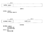
図56は、上述した第1実施形態において図34に示した一般的なコントロールレジスタ及びレスポンスレジスタの構成を、第2実施形態において改良した構成を示す図である。第2実施形態においては、図56の下部に示すレスポンスレジスタ構成において、レスポンスコマンド56-2として03hのBLOCK RETRYが追加されていることを特徴とする。ここでBLOCK RETRYとは、例えばプリンタ側が持つ空きバッファ数が1となった場合等において、画像供給デバイスへ画像データの再転送を要求することを示す返答である。従って、レスポンスコマンド56-2が03hであればBLOCK RETRYを表し、即ち画像データの再転送を要求することを示す。
【0181】
図57は、第2実施形態におけるRETRY,GETSTATUSコマンド制御手順を示す図であり、上述した第1実施形態において図45に示したDUMMY,GETSTATUSコマンド制御手順に対応するものであるが、以下の点において図45と異なることを特徴とする。まず、図45のステップS45-3ではBLOCK countを1で戻していたのに対し、図57のステップS57-3ではBLOCK RETRYを戻している点が異なる。そして、図45のステップS45-4ではブロックレジスタにDUMMYコマンドを書き込んでいるのに対して、図57のステップS57-4では、ステップS57-1に示す直前のSENDコマンドと同じデータを書き込んでいる点が異なる。尚、図57における他の処理は図45と同様であるため、説明を省略する。
【0182】
以下、第2実施形態における画像供給デバイス側の処理及びプリンタ側の処理を、図58〜図60を参照して詳細に説明する。
[画像供給デバイスにおける画像転送処理]
図58は、第2実施形態における画像供給デバイスの画像転送処理を示すフローチャートであり、実質的にステップS1200におけるSENDコマンド処理を行なう。
【0183】
図59は、上述したステップS1200のSENDコマンド処理の詳細を示すフローチャートである。まずステップS1300でGETSTATUSコマンド要求があるか否かの判定を行う。尚、GETSTATUSコマンドの起動は、第1実施形態で示した図52と同様に行われる。ステップS1300で要求があればステップS1301へ進み、GETSTAUSコマンド処理を実行する。このGETSTATUSコマンド処理は、第1実施形態において図51で示したプリンタのステイタスを取り出す処理と同様である。ステップS1301のGETSTATUSコマンド処理が終了すると、処理はステップS1300に戻る。
【0184】
ステップS1300でGETSTATUSコマンド要求がなければステップS1302へ進み、レスポンスレジスタにBLOCK RETRYが書かれたか否かをチェックする。BLOCK RETRYが書かれていれば、プリンタのもつ空きバッファが残り1つであり、データの再転送を要求していることを示しているため、処理はステップS1303へ進んで、プリンタ側のコントロールレジスタに対して1つ前のSENDコマンドで書き込まれたデータを再度書き込む。これは、図57のステップS57-4,S57-15に相当する。ステップS1302でBLOCK RETRYでなければ、ステップS1304へ進んでSENDコマンドの転送処理を実行する。これは、図57のステップS57-1,S57-18,S57-21に相当し、プリンタへ画像データを送る処理となる。ここで、画像データが1つのバッファに収まらないような場合、第1実施形態において図39で示したように、該イメージデータは複数のSNEDコマンドに分割されてプリンタのブロックレジスタに書き込まれる。ステップS1303,S1304は分割された画像データの1つを書き込む処理に相当し、ステップS1304が繰り返し実行されることにより、画像データ全体が転送される。
【0185】
次にステップS1305へ進み、プリンタ側のコントロールレジスタにBLOCK COMPLETEを書き込む。このBLOCK COMPLETEの書き込みにより、ブロックレジスタへのデータ書き込みの終了がプリンタ側に通知される。次にステップS1306へ進み、タイムアウトかどうかをチェックする。即ち、ステップ1305でプリンタのコントロールレジスタにBLOCK COMPLETEを書き込んでから画像供給デバイスのレスポンスレジスタにBLOCK ACK/NACK又はRETRYが戻されるまでの時間をタイマにより計測し、所定時間が経過してもBLOCK ACK/NACK及びRETRYが戻されない場合に、タイムアウトとなる。ステップS1306でタイムアウトととなった場合、ステップS1307へ進みタイムアウト処理を行なう。ここでタイムアウト処理は、ユーザに何らかの理由でタイムアウトが発生し、プリンタへのデータ送信がうまくいかなかったことを報知したり、プリンタへの画像転送処理を終了する処理である。タイムアウト処理後、SENDコマンド処理は終了する。
【0186】
ステップS1306においてタイムアウトでない場合、ステップS1308へ進んでプリンタから画像供給デバイスのレスポンスレジスタにBLOCK NACKが戻されたか否かをチェックする。BLOCK NACKが戻された場合、プリンタへ送ったデータに何らかの不具合があったため、ステップS1309のNACK処理へ進む。ステップS1309のNACK処理は、タイムアウト処理と同様に何らかの理由でプリンタへのデータ送信がうまくいかなかったため、プリンタへの画像転送処理を終了することを行う。NACK処理後、SENDコマンド処理は終了する。
【0187】
ステップS1308においてBLOCK NACKでない場合、ステップS1310へ進んでプリンタからBLOCK RETRYが戻されたか否かをチェックし、BLOCK RETRYが戻されればステップS1300へ戻る。BLOCK RETRYが戻されなければステップS1311へ進み、BLOCK ACKがプリンタから戻されたか否かをチェックし、BLOCK ACKでなければステップS1306へ戻る。BLOCK ACKならばステップS1312へ進み、SNEDコマンドが終了したか否かをチェックする。終了でなければステップS1300へ戻り、上述した処理を繰り返す。一方、ステップS1312でSENDコマンドが終了していれば、SENDコマンド処理は終了となる。
【0188】
以上、図59を参照して説明したように、第2実施形態の画像供給デバイスにおいては、SNEDコマンドの実行とBLOCK RETRYに対する処理、及びSENDコマンド実行中のGETSTATUSコマンドの処理が行えることが分かる。これは、上述した図57で説明したRETRY,GETSTATUSコマンド制御手順において画像供給デバイス側の手順に相当する処理である。
[プリンタにおける画像転送処理]
図60は、第2実施形態のプリンタにおけるSENDコマンド処理を詳細に示すフローチャートである。
【0189】
まずステップS1400で、プリンタ側のコントロールレジスタにBLOCK COMPLETEが書き込まれたかをチェックする。BLOCK COMPLETEが書き込まれていなければステップS1401へ進み印字処理を実行し、ステップS1400へ戻る。この印字処理は、第1実施形態で説明した図53のステップS901と同様である。ステップS1400でBLOCK COMPLETEが書き込まれていれば、ステップS1402へ進んで書き込まれたコマンドを取り込む。このコマンドは、上述した図35に示したように、CommandID35-1とParameter35-2からなり、このCommandIDを調べることによりコマンドの種類を知ることができる。
【0190】
次にステップS1403へ進み、書き込まれたコマンドがGETSTATUSコマンドであるか否か、即ち、CommandIDがGETSTATUSコマンドを示しているかをチェックする。GETSTATUSコマンドであればステップS1404へ進み、プリンタ側のGETSTATUSコマンド処理を実行した後、ステップS1400へ戻る。このGETSTATUSコマンド処理は、第1実施形態で示した図55と同様である。ステップS1403でGETSTATUSコマンドでなければ、該コマンドはSENDコマンドであるとしてステップS1405へ進み、BLOCK countが1より大きいか否かをチェックする。
【0191】
BLOCK countが1より大きければステップS1408へ進み、SENDコマンドによって送られた画像データが正常であるか否かをチェックする。正常でなければステップS907へ進み、画像供給デバイスのレスポンスレジスタにBLOCK NACKを書き込む。これにより、画像データが正しく送られてこなかったことが画像供給デバイスに通知されたことになる。ステップS1406で画像データが正常であればステップS1408へ進み、ブロックレジスタへ書き込まれた画像データを内部の適当なバッファへ移動する。これは即ち、ブロックレジスタ内の画像データを図33の33-2〜33-7で示したバッファのいずれかへ移動する処理である。そしてステップS1409へ進み、残りの空きバッファ数を示すBLOCK countを1減算する。次にステップS1410へ進み、画像供給デバイスのレスポンスレジスタにBLOCK ACKを書き込んでステップS1400へ戻る。
【0192】
一方、ステップS1405でBLOCK countが1であれば、ステップS1411へ進んでんでT1'時間のウェイトを行う。ここでT1'は、上述した図48に示すBLOCK COMPLETEに対してBLOCK ACKを戻すまでの応答時間であり、図47に示すT1よりも長い時間が設定される。そしてT1'時間の経過後、ステップS1412でSENDコマンドの再送を促すBLOCK RETRYを画像供給デバイスのレスポンスレジスタに書き込んでステップS1400に戻る。第2実施形態では、上述した第1実施形態において図47,図48で示したDUMMYコマンドの転送処理に代えて、SENDコマンドの再送を行なうことを特徴とする。従って、このT1'時間によりBLOCK RETRYが戻されるまでの時間が調整され、結果として画像供給デバイスからプリンタへ再送されるSENDコマンド数を減らすことができる。
【0193】
以上、図60に示したSENDコマンド処理により、プリンタ側での画像データ受け取り処理が実行され、SENDコマンド実行中にGETSTATUSコマンド処理が可能となるばかりでなく、BLOCK countで示される空きバッファ数によりSENDコマンドの再送処理が可能となる。
【0194】
以上、図56〜図60を参照して説明したように第2実施形態によれば、画像供給デバイスはプリンタから返送されるBLOCK ACK/NACK及びBLOCK RETRYにより、プリンタが現在有する空きバッファ数が1となった場合にSENDコマンドの再転送処理が実行できる。また、SNEDコマンドの再転送実行中にGETSTATUSコマンドが実行できるため、SENDコマンド実行中であっても任意にGETSTATUSコマンドを実行することができる。
【0195】
また、このSENDコマンドの再送処理においては、既存のバスリセットやエラー処理等を利用することができるため、新たな処理を追加することなく実現できる。
【0196】
また、プリンタ側でSENDコマンドが再送される時間間隔を調整することができるため、画像供給デバイスに負荷をかけることなく、1394シリアルバス上のトラフィックを効率化することができる。
【第3実施形態】
以下、本発明に係わる第3実施形態について説明する。
[レジスタ]
図61は、上述した第1実施形態において図34に示した一般的なコントロールレジスタ及びレスポンスレジスタの構成を、第3実施形態において改良した構成を示す図である。
【0197】
第3実施形態においては、図61に示すコントロールレジスタ構成において、コントロールコマンドとして02hのBLOCK DUMMY COMPLETEが追加されていることを特徴とする。ここで、BLOCK DUMMY COMPLETEとは、第1実施形態においては、DUMMYコマンドを書き込んだ後、BLOCK COMPLETEを書き込んでDUMMYコマンドをプリンタ側に通知するものであったのに対して、コントロールレジスタのコマンドにBLOCK DUMMY COMPLETEを持つことでプリンタ側はBLOCK DUMMY COMPLETEがコントロールレジスタに書き込まれたことを検知することで、第1実施形態と同様の働きを行わせるものである。
【0198】
図62は、第3実施形態の実施例におけるDUMMY処理の制御手順を示す図であり、上述した第1実施形態において図44に示したDUMMY処理の制御手順に対応するものであるが、以下の点において図44と異なることを特徴とする。まず、図44のステップS44-11,S44-14ではWriteBlockでDUMMYコマンドを書き込んでいたのに対して図62ではこのステップがなくなっている点が異なる。そして、図44のステップS44-12,S44-15ではBLOCK COMPLETEをコントロールレジスタに書き込んでいるのに対して、図62ではステップS62-11,S62-13でBLOCK DUMMY COMPLETEを書き込んでいる点が異なる。尚、図62における他の処理は図44と同様であるため、説明は省略する。
【0199】
図63は、第3実施形態の実施例におけるDUMMY処理、GETSTATUSコマンドの制御手順を示す図であり、上述した第1実施形態において図45に示したDUMMY処理、GETSTATUSコマンドの制御手順に対応するものであるが、以下の点において図45と異なることを特徴とする。まず、図45のステップS45-4,S45-15ではWriteBlockでDUMMYコマンドを書き込んでいたのに対して図63ではこのステップがなくなっている点が異なる。そして、図45のステップS44-6,S44-16ではBLOCK COMPLETEをコントロールレジスタに書き込んでいるのに対して、図63ではステップS63-5,S63-14でBLOCK DUMMY COMPLETEを書き込んでいる点が異なる。尚、図62における他の処理は図44と同様であるため、説明は省略する。
【0200】
図64は、第3実施形態の実施例におけるイメージ送信処理に先立って行われるDUMMY処理の制御手順を示す図であり、上述した第1実施形態において図46に示したDUMMY処理の制御手順に対応するものであるが、以下の点において図46と異なることを特徴とする。まず、図46のステップS46-1ではWriteBlockでDUMMYコマンドを書き込んでいたのに対して図64ではこのステップがなくなっている点が異なる。そして、図46のステップS46-2ではBLOCK COMPLETEをコントロールレジスタに書き込んでいるのに対して、図64ではステップS64-1でBLOCK DUMMY COMPLETEを書き込んでいる点が異なる。尚、図64における他の処理は図46と同様であるため、説明は省略する。
【0201】
以下、第3実施形態における画像供給デバイス側の処理及びプリンタ側の処理を、図65〜図67を参照して詳細に説明する。
[画像供給デバイスにおける画像転送処理]
図65は、第3実施形態の実施例におけるイメージ送信処理の詳細を示すフローチャートであり、上述した第1実施形態において図49に示したイメージ送信処理の詳細を示すフローチャートに対応するものであるが、以下の点において図49と異なることを特徴とする。まず、図49のステップS500では、WriteBlockでDUMMYコマンドを書き込んでいたのに対して図65ではBLOCK DUMMY COMPLETEを書き込んでいる点が異なる。尚、図65における他の処理は図49と同様であるため、説明は省略する。
【0202】
図66は、第3実施形態の実施例におけるSENDコマンド処理の詳細を示すフローチャートであり、上述した第1実施形態において図50に示したSENDコマンド処理の詳細を示すフローチャートに対応するものであるが、以下の点において図50と異なることを特徴とする。まず、図50のステップS604ではWriteBlockでDUMMYコマンドを書き込んでステップS606へ進んでいたのに対して図66ではステップS1604でBLOCK DUMMY COMPLETEを書き込んでステップS1607へ進んでいる点が異なる。尚、図66における他の処理は図50と同様であるため、説明は省略する。
[プリンタにおける画像転送処理]
図67は、第3実施形態の実施例におけるプリンタ側でのSENDコマンド処理の詳細を示すフローチャートであり、上述した第1実施形態において図53に示したプリンタ側でのSENDコマンド処理の詳細を示すフローチャートに対応するものである。
【0203】
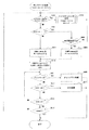
まず、ステップS1700で、プリンタ側のコントロールレジスタにBLOCK DUMMY COMPLETEが書き込まれたかどうかをチェックする。BLOCK DUMMY COMPLETEが書き込まれていればステップS1701へ進み、画像供給デバイスのレスポンスレジスタにBLOCK ACKを書き込んでステップS1700に戻る。ステップS1700でBLOCK DUMMY COMPLETEが書き込まれていなければ、ステップS1702へ進み、BLOCK COMPLETEが書き込まれたかどうかをチェックする。BLOCK COMPLETEが書き込まれていなければステップS1703へ進み、印字処理を実行した後ステップS1700へ戻る。印字処理は第1実施形態の図54で説明したものと同様である。ステップS1702でBLOCK COMPLETEが書き込まれていれば、ステップS1704へ進んで書き込まれたコマンドを書き込む。このコマンドは第1実施形態の図35に示したように、CommandID35-1とParameter35-2からなり、このCommandIDを調べることによりコマンドの種類を知ることができる。次にステップS1705へ進み、ブロックレジスタに書き込まれたコマンドがGETSTATUSコマンドであるか否か、すなわち、CommandIDがGETSTATUSコマンドを示しているかどうかをチェックする。GETSTATUSコマンドであればステップS1706へ進み、プリンタ側のGETSTATUS処理を実行する。GETSTATUS処理は第1実施形態の図55で説明したものと同様である。GETSTATUS処理の実行後は、ステップS1700へ戻る。ステップS1705でGETSTATUSコマンドでなければ、ステップS1707へ進み、該コマンドがSENDコマンドであるためSENDコマンドによって送られてきた画像データが正常であるか否かをチェックする。正常でなければ、ステップS1708へ進み、画像供給デバイスのレスポンスレジスタにBLOCK NACKを書き込む。これにより、画像データが正しく送られてこなかったことが画像供給デバイスに通知されたことになる。ステップS1707で画像データが正常であればステップS1709へ進み、ブロックレジスタへ書き込まれた画像データを内部の適当なバッファへ移動する。これは即ち、ブロックレジスタ内の画像データを図33の33-2〜33-7で示したバッファのいずれかへ移動する処理である。そしてステップS1710へ進み、残りの空きバッファ数を示すBLOCK countを1減算する。次にステップS1711へ進み、画像供給デバイスのレスポンスレジスタにBLOCK ACKを書き込んでステップS1700へ戻る。
【0204】
以上、図61〜図67を参照して説明したように第3実施形態によれば、画像供給デバイスは、プリンタからのレスポンスレジスタに書き込まれるBLOCK ACK/NACK及びBLOCK countにより、プリンタが現在有する空きバッファ数を知ることができ、空きバッファ数が1となった場合に、SENDコマンドに変えてプリンタ側のコントロールレジスタにBLOCK DUMMY COMPLETEを書き込む処理が実行できる。また、DUMMY処理実行中にGETSTATUSコマンドが実行できるため、SENDコマンド実行中であっても、任意にGETSTATUSコマンドを実行することができる。
【実施形態の変形例】
なお、上述した第1及び第2実施形態においては、プリンタ内の空きバッファ数が1となった場合に、DUMMYコマンド処理やBLOCK RETRYの処理を行なう例について説明したが、この空きバッファ数は1に限られるわけではない。SENDコマンド処理を実行するのに不都合が生じるような数であればどのような数であっても良く、例えば2や3であっても構わない。
【0205】
また、各実施形態においては画像供給デバイスからプリンタへデータ転送を行なうことによって印字処理を実現する例について説明したが、本発明は画像データを転送して利用する機器であれば、どのような装置にも適用可能である。
【0206】
また、上述した第1実施形態においては、DUMMYコマンドをプリンタ内の空きバッファ数が1となった場合に転送するとして説明したが、画像供給デバイスからプリンタへ送られるコマンドであって、プリンタ内の空きバッファ数が得られ、プリンタでの処理負荷の少ないものであれば、どのようなコマンドを使用しても良い。
【0207】
また、各実施形態においては、BLOCK countに空きバッファ数をセットして通知する例について説明したが、空きバッファの数そのものでなく、「空きバッファあり」、「空きバッファ少ない」等のバッファ情報をセットする方法も考えられる。この方法でもバッファの状態を画像供給デバイスに通知することができるため、上述した各実施形態と同様の効果を得られる。
【0208】
また、上述した各実施形態においてはIEEE1934に規定されるシリアルインタフェイスを用いてネットワークを構成する例を説明したが、本発明はこれに限定されるものではなく、Universal Serial Bus(USB)と呼ばれるシリアルインタフェイスなど、任意のシリアルインタフェイスを用いて構成されるネットワークにも適用することができる。
【他の実施形態】
なお、本発明は、複数の機器(例えばホストコンピュータ,インタフェイス機器,リーダ,プリンタなど)から構成されるシステムに適用しても、一つの機器からなる装置(例えば、複写機,ファクシミリ装置など)に適用してもよい。
【0209】
また、本発明の目的は、前述した実施形態の機能を実現するソフトウェアのプログラムコードを記録した記憶媒体を、システムあるいは装置に供給し、そのシステムあるいは装置のコンピュータ(またはCPUやMPU)が記憶媒体に格納されたプログラムコードを読出し実行することによっても、達成されることは言うまでもない。この場合、記憶媒体から読出されたプログラムコード自体が前述した実施形態の機能を実現することになり、そのプログラムコードを記憶した記憶媒体は本発明を構成することになる。プログラムコードを供給するための記憶媒体としては、例えば、フロッピディスク,ハードディスク,光ディスク,光磁気ディスク,CD-ROM,CD-R,磁気テープ,不揮発性のメモリカード,ROMなどを用いることができる。
【0210】
また、コンピュータが読出したプログラムコードを実行することにより、前述した実施形態の機能が実現されるだけでなく、そのプログラムコードの指示に基づき、コンピュータ上で稼働しているOS(オペレーティングシステム)などが実際の処理の一部または全部を行い、その処理によって前述した実施形態の機能が実現される場合も含まれることは言うまでもない。
【0211】
さらに、記憶媒体から読出されたプログラムコードが、コンピュータに挿入された機能拡張カードやコンピュータに接続された機能拡張ユニットに備わるメモリに書込まれた後、そのプログラムコードの指示に基づき、その機能拡張カードや機能拡張ユニットに備わるCPUなどが実際の処理の一部または全部を行い、その処理によって前述した実施形態の機能が実現される場合も含まれることは言うまでもない。
【0212】
【発明の効果】
以上説明したように、本発明によれば、1394シリアルバスなどによりホストデバイスとターゲットデバイスを接続し、ホストデバイスからターゲットデバイスへ送られるデータの転送について、コマンドとデータとで同じレジスタ領域を使用し、かつレジスタへのデータの書き込みに対する応答のみを行う際に、データ転送以外のコマンドを任意に実行可能なデータ転送装置、データ転送システムおよびその方法、画像処理装置、並びに、記録媒体を提供することができる。すなわち、本発明によれば、ホストデバイスがターゲットデバイスにおける空きバッファ数に応じてダミー処理を実行することにより、データ転送中であっても他のコマンドが任意に実行できる。
【0213】
また、レジスタへのデータの書き込みに対する応答時間を調整することにより、データバス上のトラフィックの効率化を実現するデータ転送装置、データ転送システムおよびその方法、画像処理装置、並びに、記録媒体を提供することができる。
【0214】
【図面の簡単な説明】
【図1】本発明を適用するシステムの一般的な構成例を示す図、
【図2】 1394シリアルバスによるネットワークの構成例を示す図、
【図3】 1394シリアルバスの構成例を示す図、
【図4】 1394シリアルバスにおけるアドレス空間の一例を示す図、
【図5】 1394シリアルバス用のケーブルの断面を示す図、
【図6】 1394シリアルバスで採用されている、データ転送方式のDS-Link方式を説明するための図、
【図7】バスリセット信号の発生から、ノードIDが決定し、データ転送が行えるようになるまでの一連のシーケンス例を示すフローチャート、
【図8】バスリセット信号の監視からルートノードの決定までの詳細例を示すフローチャート、
【図9】ノードID設定の詳細例を示すフローチャート、
【図10】 1394シリアルバスのネットワーク動作例を示す図、
【図11】 1394シリアルバスのCSRアーキテクチャの機能を示す図、
【図12】 1394シリアルバスに関するレジスタを示す図、
【図13】 1394シリアルバスのノード資源に関するレジスタを示す図、
【図14】 1394シリアルバスのコンフィギュレーションROMの最小形式を示す図、
【図15】 1394シリアルバスのコンフィギュレーションROMの一般形式を示す図、
【図16】バス使用権の要求を説明する図、
【図17】バス使用の許可を説明する図、
【図18】 1394シリアルバスにおけるアービトレーションの流れを示すフローチャート、
【図19】トランザクションレイヤにおけるCSRアーキテクチャに基づくリード、ライト、ロックの各コマンドの要求・レスポンスプロトコルを示す図、
【図20】リンクレイヤにおけるサービスを示す図、
【図21】非同期転送における時間的な遷移を示す図、
【図22】非同期転送用パケットのフォーマットを示す図、
【図23】スプリットトランザクションの動作例を示す図、
【図24】スプリットトランザクションを行う場合の転送状態の時間的遷移例を示す図、
【図25】同期転送における時間的な遷移を示す図、
【図26】同期転送用のパケットフォーマット例を示す図、
【図27】 1394シリアルバスにおける同期転送のパケットフォーマットのフィールドの詳細を示す図、
【図28】同期転送と非同期転送が混在するときの転送状態の時間的遷移を示す図、
【図29】 1394シリアルバスのレイヤ構造を示す図、
【図30】データ転送用のレジスタ構成を示す図、
【図31】画像供給デバイスからプリンタに対するコマンド制御の概要を示す図、
【図32】プリンタから画像供給デバイスに対するリプライ制御の概要を示す図、
【図33】プリンタにおけるブロックレジスタと内部バッファ構成を示す図、
【図34】コントロール,レスポンスレジスタの一般的な構成を示す図、
【図35】コマンド構成を示す図、
【図36】 SEND,GETSTATUSコマンドの構成を示す図、
【図37】 SEND,GETSTATUSリプライの構成を示す図、
【図38】 GETSTATUSコマンドのステイタスを示す図、
【図39】 SENDコマンドにおける画像データ分割の様子を示す図、
【図40】画像供給デバイスとプリンタの一般的な制御手順を示す図、
【図41】 GETSTATUSコマンドの制御手順を示す図、
【図42】コントロール,レスポンスレジスタの構成を示す図、
【図43】 DUMMYコマンドの構成を示す図、
【図44】 DUMMYコマンドの制御手順を示す図、
【図45】 DUMMY,GETSTATUSコマンドの制御手順を示す図、
【図46】 SENDコマンド前のDUMMYコマンドの制御手順を示す図、
【図47】 DUMMYコマンドの一般的な制御手順を示す図、
【図48】トラフィック効率化のためのDUMMYコマンドの制御手順を示す図、
【図49】画像供給デバイスにおける画像転送処理を示すフローチャート、
【図50】画像供給デバイスにおけるSENDコマンド処理を示すフローチャート、
【図51】画像供給デバイスにおけるGETSTATUSコマンド処理を示すフローチャート、
【図52】画像供給デバイスにおけるタイマ割り込み処理を示すフローチャート、
【図53】プリンタにおけるSENDコマンド処理を示すフローチャート、
【図54】プリンタにおける印字処理を示すフローチャート、
【図55】プリンタにおけるGETSTATUSコマンド処理を示すフローチャート、
【図56】第2実施例におけるコントロール,レスポンスレジスタの構成を示す図、
【図57】第2実施例におけるRETRY、GETSTATUSコマンドの制御手順を示す図、
【図58】第2実施例の画像供給デバイスにおける画像転送処理を示すフローチャート、
【図59】第2実施例の画像供給デバイスにおけるSENDコマンド処理を示すフローチャート、
【図60】第2実施例のプリンタにおけるSENDコマンド処理を示すフローチャートである。
【図61】本発明に係る第3実施形態におけるコントロールレジスタ、レスポンスレジスタの構成を示す図である。
【図62】第3実施形態におけるDUMMY処理の制御手順を示す図である。
【図63】第3実施形態におけるDUMMY処理、GETSTATUSコマンドの制御手順を示す図である。
【図64】第3実施形態におけるSENDコマンド前のDUMMY処理の制御手順を示す図である。
【図65】第3実施形態の画像供給デバイスにおける画像転送処理を示すフローチャートである。
【図66】第3実施形態の画像供給デバイスにおけるSENDコマンド処理を示すフローチャートである。
【図67】第3実施形態のプリンタにおけるSEND処理を示すフローチャートである。[0001]
BACKGROUND OF THE INVENTION
The present invention relates to a data transfer apparatus, a data transfer system and method, an image processing apparatus, and a recording medium. For example, an image supply device and an image processing device are directly connected via a serial interface defined by IEEE1394 or the like. Data transfer apparatus, data transfer system and method, image processing apparatus, and recording medium.
[Prior art]
The printer is connected to a personal computer (PC) as a host device via a parallel or serial interface such as Centronics or RS232C.
[0002]
Also, digital devices that are image supply devices such as scanners, digital still cameras, and digital video cameras are connected to the PC. Image data captured by each digital device is temporarily captured on a hard disk on a PC, then processed by application software on the PC, etc., and converted into print data for a printer, via the above interface. And sent to the printer.
[0003]
In the system as described above, driver software for controlling each digital device and printer exists independently on the PC, and the image data output from the digital device is easy to use and display on the PC with these driver software. Stored as easy-to-use data. The stored data is converted into print data by an image processing method that takes into account the image characteristics of the input device and the image characteristics of the output device.
[0004]
Today, an image supply device and a printer can be directly connected with a new interface such as an interface defined by IEEE1394 (hereinafter referred to as “1394 serial bus”). When an image supply device and a printer are directly connected by a 1394 serial bus, a method of including print data in an operand of an FCP (Function Control Protocol) can be considered. In addition, in the 1394 serial bus, a method for transferring data by providing a register area for data transfer and writing data in the register area is also conceivable.
[0005]
A method of instructing data transfer using a command instructing start of data transfer and a response to the command is also conceivable.
[Problems to be solved by the invention]
However, the above-described technique has the following problems. As described above, since the image data output from the image supply device is converted to print data by the PC and printed by the printer, even if the image supply device and the printer are directly connected, printing is possible without the PC. Can not do. There is also a printer called a video printer that directly prints image data output from a digital video camera, but it can only be connected between specific models, and a highly versatile video printer that can be directly connected to many image supply devices Absent. In other words, it is not possible to directly send image data from an image supply device to a printer for printing by making use of a function for directly connecting devices such as a 1394 serial bus.
[0006]
The method described above, in which the image supply device and printer are directly connected via the 1394 serial bus and the print data is included in the operand of the FCP, has the problem that the control command and the print data cannot be separated, and there is always a response to the command. There is also a problem that transfer efficiency is low because it is necessary. Further, the above-described method for providing a register area for data transfer requires a process for determining whether data can be written to the register area every time data is transferred. Therefore, the overhead of this determination process is increased, and there is a problem that the transfer efficiency is lowered.
[0007]
In order to solve this problem, a method of using the same register area without separating data and commands can be considered. This method can reduce the register area used and provide a simpler data transfer method. Further, it is not determined whether or not the register area to which data is written is writable, and after writing the data to the register, only a correct / incorrect response to the write is performed, and if there is a successful response, the next data is transferred Is also possible.
[0008]
Although this method has an advantage of simplifying the data transfer procedure, there arises a problem that a buffer for storing an area where data is written on the data receiving side becomes full. As soon as the data is written to the register and saved in its own buffer, the data receiving side returns a response indicating that data can be received. The data transfer side that has received a response indicating that the data can be received tries to start transfer of the next data immediately. Therefore, if the processing on the data receiving side is slower than the data transferring side, the buffer on the data receiving side is always full.
[0009]
The data receiving side cannot return a reception ready response to the data sending side until the processing proceeds and an empty buffer is created after storing the data of the last empty buffer. In this case, since the same register area is used for the command and the data, the command other than the data transfer cannot be executed if there is no space in the buffer on the data receiving side during the execution of the command for transferring the data.
[0010]
This means that when a printer is considered as the data receiving side, there are cases where a command for obtaining the printer status (paper out, error, etc.) can be executed and cannot be executed during data transfer. That is, when the printer has an empty buffer and a command for obtaining a status can be received, the command can be executed, but when there is no empty buffer, the command cannot be executed or the command is kept waiting until an empty buffer is formed. Therefore, a problem occurs particularly when performing status acquisition that requires real-time performance. There is also a problem that it is impossible to determine whether the status is at a required time.
[0011]
Further, since the response to the transfer is performed in a substantially constant short time after the data is transferred, the amount of data flowing on the data bus is increased, and there is a problem with respect to the effective use of the bus.
[0012]
Also, when data transfer is instructed using the command for instructing the start of data transfer and the response to the command described above, the exchange of the command and response occurs for each unit of data transfer, which also reduces the transfer efficiency. Problem occurs.
[0013]
The present invention is for solving the above-mentioned problems individually or collectively, and connects a host device and a target device by a 1394 serial bus or the like, and transfers commands sent from the host device to the target device. Data transfer device, data transfer system and method, and image processing device capable of arbitrarily executing commands other than data transfer when using the same register area for data and only performing a response to writing data to the register In addition, an object is to provide a recording medium.
[0014]
Another object of the present invention is to provide a data transfer device, a data transfer system and method, an image processing device, and a recording medium that realize efficiency of traffic on a data bus by adjusting a response time for data transfer. To do.
[0015]
[Means for Solving the Problems]
The present invention has the following configuration as one means for achieving the above object.
[0016]
The data transfer method according to the present invention includes: Host device A data transfer method used between the target device and the target device, Should be stored in the buffer of the target device The first data From the host device to the target device transfer A first transfer step to , The first data Indicates the free space of the buffer as a response to Buffer information From the target device to the host device Reply A first reply step to , When the free capacity indicated by the buffer information is not larger than a predetermined capacity, a second transfer step of transferring specific data from the host device to the target device, and without storing the specific data in the buffer, A second reply step of returning buffer information indicating the free capacity of the buffer as a response to the specific data from the target device to the host device; and the specific data is transferred from the host device to the target device. And a third transfer step of transferring second data to be stored in the buffer from the host device to the target device when the free capacity indicated by the buffer information is larger than a predetermined capacity. It is characterized by that.
[0017]
In addition, data according to the present invention A receiving device receiving first data to be stored in the buffer from a host device; and buffer information indicating a free capacity of the buffer as a response to the first data to the host device. A first transmitting means for transmitting; a second receiving means for receiving specific data from the host device if the free capacity indicated by the buffer information is not greater than a predetermined capacity; and the specific data in the buffer. Second transmission means for transmitting buffer information indicating the free capacity of the buffer to the host device as a response to the specific data without storing; and after receiving the specific data from the host device, the buffer The second data to be stored in the buffer when the free capacity indicated by the information is larger than a predetermined capacity And receiving from the host device, the host device transfers the specific data to the data receiving device when the free capacity indicated by the buffer information is not larger than a predetermined capacity. It is characterized by that.
[0018]
In addition, data according to the present invention The transfer apparatus includes: first transfer means for transferring first data to be stored in a buffer of a target device to the target device; and buffer information indicating a free capacity of the buffer as a response to the first data. A first receiving means for receiving from the target device; a second transferring means for transferring specific data to the target device if the free capacity indicated by the buffer information is not greater than a predetermined capacity; and Second response means for receiving buffer information indicating the free capacity of the buffer from the target device as a response; and after the specific data is transferred to the target device, the free capacity indicated by the buffer information is a predetermined capacity. If it is greater, the second data to be stored in the buffer is transferred to the target. A third transfer means for transferring to the network device, wherein the target device stores the buffer information indicating a free capacity of the buffer as a response to the specific data without storing the specific data in the buffer. Send to data transfer device It is characterized by that.
[0019]
[Outline of IEEE 1394]
With the advent of home digital VTRs and digital video discs (DVDs), it is necessary to transfer real-time and large-volume data such as video data and audio data (hereinafter collectively referred to as “AV data”). . In order to transfer AV data to a PC or other digital devices in real time, an interface having a high-speed data transfer capability is required. The interface developed from such a viewpoint is the 1394 serial bus.
[0020]
FIG. 2 shows an example of a network system configured using a 1394 serial bus. This system includes devices A to H, and AB, AC, BD, DE, CF, CG, and CH are connected by a twisted pair cable for a 1394 serial bus. Examples of these devices A to H are host computer devices such as personal computers and computer peripheral devices. Computer peripherals include digital VCRs, DVD players, digital still cameras, storage devices that use media such as hard disks and optical discs, CRT and LCD monitors, tuners, image scanners, film scanners, printers, MODEMs, and terminal adapters (TA) All computer peripherals such as The recording method of the printer may be any method such as an electrophotographic method using a laser beam or LED, an ink jet method, an ink melting type or sublimation type thermal transfer method, or a thermal recording method.
[0021]
Connection between devices can be a mixture of the daisy chain method and the node branch method, and a connection with a high degree of freedom can be performed. In addition, each device has an ID, and recognizes each other to form one network within the range connected by the 1394 serial bus. For example, by simply daisy-chaining each device with a single 1394 serial bus cable, each device plays the role of relay, so that one network can be configured as a whole.
[0022]
The 1394 serial bus is compatible with the Plug and Play function, and has a function of automatically recognizing a device and recognizing a connection state simply by connecting a 1394 serial bus cable to the device. In addition, in the system shown in Fig. 2, when a device is removed from the network or is newly added, the bus is automatically reset (the network configuration information up to that point is reset) to create a new one. A good network. This function makes it possible to always set and recognize the network configuration at that time.
[0023]
The data transfer rate of the 1394 serial bus is defined as 100/200/400 Mbps, and compatibility is maintained by a device having a higher transfer rate supporting a lower transfer rate. As the data transfer mode, there are an asynchronous transfer mode (ATM) for transferring asynchronous data such as a control signal and a synchronous transfer mode for transferring synchronous data such as real-time AV data. Asynchronous data and synchronous data are mixed in the cycle while giving priority to the transfer of synchronous data following the transfer of the cycle start packet (CSP) indicating the cycle start in each cycle (usually 125μs / cycle). Transferred.
[0024]
FIG. 3 is a diagram showing a configuration example of the 1394 serial bus. The 1394 serial bus has a layer structure. As shown in FIG. 3, the connector port 810 is connected to the connector at the end of the cable 813 for the 1394 serial bus. Above the connector port 810, there are a
[0025]
The
[0026]
The
[0027]
FIG. 4 is a diagram showing an example of an address space in the 1394 serial bus. Each device (node) connected to the 1394 serial bus must have a unique 64-bit address. This address is stored in the memory of the device, and by always recognizing the node address of itself or the other party, data communication specifying the other party can be performed.
[0028]
The addressing of the 1394 serial bus is based on the IEEE1212 standard, and the address setting uses the first 10 bits for specifying the bus number and the next 6 bits for specifying the node ID.
[0029]
The 48-bit address used in each device is also divided into 20 bits and 28 bits, and is used with a structure of 256 Mbyte units. Of the first 20-bit address space, 0 to 0xFFFFD is called a memory space, 0xFFFFE is called a private space, and 0xFFFFF is called a register space. The private space is an address that can be freely used within the device, and the register space stores information common to the devices connected to the bus and is used for communication between the devices.
[0030]
The first 512 bytes of the register space are the CSR architecture core registers (CSR core), the next 512 bytes are serial bus registers, the next 1024 bytes are the configuration ROM, and the rest are units. Each device-specific register is placed in space.
[0031]
In general, to simplify the design of heterogeneous bus systems, nodes should use only the first 2048 bytes of the initial unit space, which results in CSR cores, serial bus registers, configuration ROMs and unit space It is desirable that the first 2048 bytes are combined to make up 4096 bytes.
[0032]
The above is the outline of the 1394 serial bus. Next, features of the 1394 serial bus will be described in more detail.
[0033]
[Details of 1394 serial bus]
[Electrical specifications of 1394 serial bus]
FIG. 5 shows a cross section of a cable for a 1394 serial bus. The 1394 serial bus cable is provided with a power line in addition to two pairs of twisted pair signal lines. As a result, it is possible to supply power to a device that does not have a power source or a device whose voltage has dropped due to a failure or the like. The voltage of the DC power supplied from the power line is specified as 8 to 40V, and the current is specified as the maximum current 1.5A. In the standard called DV cable, it is composed of four wires without the power line.
[DS-Link method]
FIG. 6 is a diagram for explaining a data transfer method DS-Link (Data / Strobe Link) method employed in the 1394 serial bus.
[0034]
The DS-Link method is suitable for high-speed serial data communication and requires two sets of signal lines. That is, the data signal is sent by one set of two pairs of twisted wires, and the strobe signal is sent by another set. The receiving side is characterized in that a clock can be generated by taking an exclusive OR of the data signal and the strobe signal. For this reason, when using the DS-Link method, there is no need to mix the clock signal in the data signal, so the clock signal can be generated with higher transfer efficiency than other serial data transfer methods, so phase locked loop (PLL) The circuit becomes unnecessary, and the circuit scale of the controller LSI can be reduced accordingly. Furthermore, since there is no need to send information indicating that the device is in an idle state when there is no data to be transferred, the transceiver circuit of each device can be put into a sleep state, and power consumption can be reduced. .
[Bus reset sequence]
Each device (node) connected to the 1394 serial bus is given a node ID and recognized as a node constituting the network. For example, when the number of nodes increases or decreases due to connection separation of network devices, power on / off, etc., that is, when there is a change in the network configuration and it is necessary to recognize a new network configuration, each node that detects the change is on the bus Then, a bus reset signal is transmitted to enter a mode for recognizing a new network configuration. This change in the network configuration is detected by detecting a change in bias voltage at the connector port 810.
[0035]
When a bus reset signal is transmitted from a certain node, the
[Node ID determination sequence]
After the bus reset, each node enters an operation of giving an ID to each node in order to construct a new network configuration. A general sequence from bus reset to node ID determination at this time will be described with reference to flowcharts shown in FIGS. FIG. 7 is a flowchart showing a series of sequence examples from the generation of the bus reset signal until the node ID is determined and data transfer can be performed. The nodes constantly monitor the generation of the bus reset signal in step S101, and when the bus reset signal is generated, the nodes move to step S102 and are directly connected to each other to obtain a new network configuration in a state where the network configuration is reset. A parent-child relationship is declared between nodes. Then, step S102 is repeated until it is determined by the determination in step S103 that the parent-child relationship has been determined among all the nodes.
[0036]
When the parent-child relationship is determined, the process proceeds to step S104, where a root node is determined. In step S105, a node ID setting operation for giving an ID to each node is performed. Node IDs are set in order of a predetermined node from the root node, and step S105 is repeated until it is determined in step S106 that all nodes have been given IDs.
[0037]
When the node ID setting is completed, the new network configuration has been recognized in all nodes, so that data transfer between the nodes can be performed, data transfer is started in step S107, and the sequence proceeds to step S101. The generation of the bus reset signal is monitored again.
[0038]
FIG. 8 is a flowchart showing a detailed example from the monitoring of the bus reset signal (S101) to the determination of the root node (S104), and FIG. 9 is a flowchart showing a detailed example of the node ID setting (S105, S106).
[0039]
In FIG. 8, the generation of the bus reset signal is monitored in step S201. When the bus reset signal is generated, the network configuration is once reset. Next, in step S202, as a first step of re-recognizing the reset network configuration, each device resets the flag FL with data indicating that it is a leaf node. Then, in step S203, each device checks the number of ports, that is, the number of other nodes connected to itself, and in step S204, depending on the result of step S203, to start declaration of parent-child relationship from now on, Check the number of ports (parent-child relationship has not been determined). Here, the number of undefined ports is equal to the number of ports immediately after the bus reset, but as the parent-child relationship is determined, the number of undefined ports detected in step S204 decreases.
[0040]
Only actual leaf nodes can declare parent-child relationships immediately after a bus reset. Whether or not the node is a leaf node can be known from the confirmation result of the number of ports in step S203, that is, if the number of ports is “1”, the node is a leaf node. In step S205, the leaf node declares the parent-child relationship to the connection partner node “I am a child, the partner is a parent”, and the operation ends.
[0041]
On the other hand, the node whose number of ports is “2 or more” in step S203, that is, the branch node is “undefined port number> 1” immediately after the bus reset, and therefore proceeds to step S206, and the flag FL indicates the branch node. Data is set, and it waits for a parent-child relationship to be declared from another node in step S207. The parent node is declared from another node, and the branch node receiving it returns to step S204 to check the number of undefined ports. If the number of undefined ports is "1", it is connected to the remaining port. In step S205, a parent-child relationship of “I am a child and the other party is a parent” can be declared to other nodes. In addition, the branch node whose number of undefined ports is still “2 or more” waits until the parent-child relationship is declared again from another node in step S207.
[0042]
If the number of undefined ports in any one of the branch nodes (or leaf nodes that did not work quickly despite exceptions being able to declare children) becomes "0", the parent-child relationship declaration for the entire network is The only node for which the number of undefined ports has become “0”, that is, the node determined to be the parent of all nodes, sets the data indicating the root node in the flag FL in step S208, and in step S209 Recognized as root node.
[0043]
In this way, the procedure from the bus reset to the declaration of the parent-child relationship between all nodes in the network is completed.
[0044]
Next, a procedure for giving an ID to each node will be described. It is a leaf node that can first set an ID. Then, IDs are set from a young number (node number: 0) in the order of leaf → branch → root.
[0045]
In step S301 in FIG. 9, the process branches to processing corresponding to the type of node, that is, leaf, branch, and route, based on the data set in the flag FL.
[0046]
First, in the case of leaf nodes, the number of leaf nodes (natural number) existing in the network is set to the variable N in step S302, and then in step S303, each leaf node requests a node number from the root node. If there are a plurality of requests, the root node performs arbitration in step S304, gives a node number to one node in step S305, and notifies the other nodes of the result indicating failure in obtaining the node number.
[0047]
The leaf node that could not obtain the node number according to the determination in step S306 repeats the node number request again in step S303. On the other hand, the leaf node that has acquired the node number notifies all the nodes by broadcasting ID information including the acquired node number in step S307. When the broadcast of the ID information ends, the variable N representing the number of leaves is decremented in step S308. Then, the procedure from step S303 to S308 is repeated until the variable N becomes “0” by the determination in step S309, and after the ID information of all the leaf nodes is broadcasted, the process proceeds to step S310 to set the branch node ID Move on.
[0048]
Branch node ID setting is performed in substantially the same manner as leaf nodes. First, in step S310, the number of branch nodes (natural number) existing in the network is set to a variable M, and then in step S311, each branch node requests a node number from the root node. In response to this request, the root node performs arbitration in step S312 and assigns a young number following the leaf node to one branch node in step S313, and results in acquisition failure for the branch node that could not acquire the node number To be notified.
[0049]
As a result of the determination in step S314, the branch node that knows that acquisition of the node number has failed repeats the request for the node number again in step S311. On the other hand, in step S315, the branch node that has acquired the node number broadcasts ID information including the acquired node number to notify all nodes. When the broadcast of the ID information ends, the variable M representing the number of branches is decremented in step S316. Then, as a result of the determination in step S317, the procedure from steps S311 to S316 is repeated until the variable M becomes “0”, and the ID information of all the branch nodes is broadcast. Move on to setting.
[0050]
At this point, the only node that has not obtained an ID is the root node. Therefore, in step S318, the youngest number not given to other nodes is set as its own node number. Broadcast ID information.
[0051]
This is the end of the procedure until all the node IDs are set. Next, a specific procedure of the node ID determination sequence will be described using the network example shown in FIG.
[0052]
In the network shown in FIG. 10, node A and node C are directly connected below node B, which is the root, node D is directly connected below node C, and node E and node F are directly connected below node D. Has a hierarchical structure. The procedure for determining the hierarchical structure, root node, and node ID is as follows.
[0053]
After the bus reset occurs, in order to recognize the connection status of each node, a parent-child relationship is declared between the ports directly connected to each node. The parent and child here means that the upper level of the hierarchical structure is “parent” and the lower level is “child”. In FIG. 10, after the bus reset, the node A first declared the parent-child relationship. As described above, the declaration of the parent-child relationship can be started from a node (leaf) to which only one port is connected. If the number of ports is “1”, it is recognized that the end of the network tree, that is, the leaf node, and the parent-child relationship is determined from the node that performed the earliest operation among those leaf nodes. Become. Thus, the port of the node that declared the parent-child relationship is set as a “child” of the two nodes connected to each other, and the node of the counterpart node is set as the “parent”. In this way, a “child-parent” relationship is set between the nodes AB, the nodes ED, and the nodes FD.
[0054]
Further, the hierarchy is advanced by one, and the parent-child relationship is declared to the higher-order node sequentially from the node having a plurality of ports, that is, the node that has received the parent-child relationship declaration from the other nodes among the branch nodes. In FIG. 10, after the parent-child relationship between the node DE and the DF is first determined, the node D declares the parent-child relationship to the node C. As a result, the “child-parent” relationship is set between the node DCs. The Node C, which has received a parent-child relationship declaration from node D, declares a parent-child relationship to node B connected to another port, and this establishes a “child-parent” relationship between nodes CB. The
[0055]
In this way, the hierarchical structure as shown in FIG. 10 is configured, and the node B that becomes the parent in all the finally connected ports is determined as the root node. Note that there is only one root node in one network configuration. In addition, if node B, which has been declared a parent-child relationship from node A, promptly declares a parent-child relationship to other nodes, another node such as node C may become the root node. . That is, depending on the timing at which the declaration of the parent-child relationship is transmitted, any node may be the root node, and even if the network configuration is the same, a specific node is not necessarily the root node.
[0056]
When the root node is determined, a determination mode for each node ID is entered. All nodes have a broadcast function for notifying all other nodes of their determined ID information. The ID information is broadcast as ID information including a node number, information on a connected position, the number of ports that are present, the number of ports that are connected, and parent-child relationship information of each port.
[0057]
As described above, node numbers are assigned from leaf nodes, and node numbers = 0, 1, 2,... Are assigned in order. Then, by broadcasting the ID information, it is recognized that the node number has already been assigned.
[0058]
When all the leaf nodes have obtained the node number, the next step is to move to the branch node and the node number following the leaf node is assigned. Similar to the leaf node, ID information is broadcast in order from the branch node to which the node number is assigned, and finally the root node broadcasts its own ID information. Therefore, the root node always has the largest node number.
[0059]
As described above, ID setting for the entire hierarchical structure is completed, a network configuration is constructed, and bus initialization is completed.
[Control information for node management]
As a basic function of the CSR architecture for node management, the CSR core shown in FIG. 4 exists on a register. The positions and functions of these registers are shown in FIG. 11. The offset in the figure is a relative position from 0xFFFFF0000000.
[0060]
In the CSR architecture, registers related to the serial bus are arranged from 0xFFFFF0000200. The location and function of these registers are shown in FIG.
[0061]
In addition, information regarding serial bus node resources is arranged at a location starting from 0xFFFFF0000800. FIG. 13 shows the positions and functions of these registers.
[0062]
The CSR architecture has a configuration ROM to represent the function of each node. This ROM has a minimum format and a general format, and is allocated from 0xFFFFF0000400. The minimum format only represents a vendor ID as shown in FIG. 14, and this vendor ID is a unique value all over the world represented by 24 bits.
[0063]
Further, the general format is as shown in FIG. 15 and has information about the node. In this case, the vendor ID can be stored in the root directory (root_directory). The bus information block and the root leaf have a 64-bit global device number including the vendor ID. This device number is used for recognizing the node continuously after reconfiguration such as bus reset.
[Serial bus management]
As shown in FIG. 3, the 1394 serial bus protocol includes a
[0064]
A node that performs bus management (hereinafter referred to as a “bus management node”) exists only on the same bus and provides a management function to other nodes on the serial bus. , Performance optimization, power management, transmission speed management, configuration management, etc.
[0065]
The bus management function is roughly divided into three functions: a bus manager, a synchronous (isochronous) resource manager, and a node control. The node control is a management function that enables inter-node communication in the
[0066]
In a configuration in which no bus management node exists on the bus, a node having a synchronous resource manager function performs a part of bus management functions such as power management and cycle master control. In addition, the bus management is a management function that provides a service that provides a bus control interface to the application. The control interface includes a serial bus control request (SB_control.request), a serial bus event control confirmation (SB _Control.confirmation) and serial bus event notification (SB_EVENT.indication).
[0067]
The serial bus control request is used when an application requests a bus management node for bus reset, bus initialization, bus status information, and the like. The serial bus event control confirmation is notified to the application from the bus management node as a result of the serial bus control request. The serial bus event notification is for notifying an event generated asynchronously from the bus management node to the application.
[Data transfer protocol]
In the data transfer of the 1394 serial bus, synchronous data (synchronous packet) that needs to be transmitted periodically and asynchronous data (asynchronous packet) that allows data transmission / reception at any timing exist at the same time. Real-time performance is guaranteed. In data transfer, bus arbitration is performed to request a bus use right prior to transfer and to obtain permission to use the bus.
[0068]
In asynchronous transfer, a transmission node ID and a reception node ID are sent as packet data together with transfer data. When the receiving node confirms its own node ID and receives the packet, it returns an acknowledge signal to the transmitting node, thereby completing one transaction.
[0069]
In synchronous transfer, a transmission node requests a synchronous channel together with a transmission rate, and a channel ID is sent as packet data together with transfer data. The receiving node confirms the desired channel ID and receives the data packet. The number of required channels and the transmission rate are determined by the
[0070]
These data transfer protocols are defined by three layers: a
[Physical layer]
Next, bus arbitration in the
[0071]
Prior to data transfer, the 1394 serial bus always performs arbitration of the right to use the bus. Each device connected to the 1394 serial bus configures a logical bus network that relays the signal transferred over the network to all devices in the network, so packet collisions Bus arbitration is necessary to prevent this. This allows only one node to perform the transfer at a certain time.
[0072]
FIG. 16 is a diagram for explaining a request for a bus use right, and FIG. 17 is a diagram for explaining permission for use of the bus. When bus arbitration starts, one or more nodes request the right to use the bus toward the parent node. In FIG. 16, node C and node F request the right to use the bus. Upon receiving this request, the parent node (node A in FIG. 16) further requests the right to use the bus toward the parent node, thereby relaying the request for the right to use the bus by node F. This request is finally delivered to the root node that performs arbitration.
[0073]
The root node that has received the request for the right to use the bus determines which node is given the right to use the bus. This arbitration work can be performed only by the root node, and a bus use permission is given to a node that has won the arbitration. FIG. 17 shows a state where the bus use permission is given to the node C and the request for the right to use the bus of the node F is denied.
[0074]
The root node sends a DP (data prefix) packet to the node losing the bus arbitration to inform that the request for the right to use the bus has been rejected. The request for the right to use the bus of the node that lost the bus arbitration is kept waiting until the next bus arbitration.
[0075]
As described above, a node that has won arbitration and has obtained permission to use the bus can subsequently start data transfer. Here, a series of bus arbitration flows will be described with reference to the flowchart shown in FIG.
[0076]
In order for a node to begin data transfer, the bus must be idle. In order to confirm that the previously started data transfer is completed and the bus is currently in an idle state, a predetermined idle time gap length (for example, subaction gap) set individually in each transfer mode When a predetermined gap length is detected, each node determines that the bus is in an idle state. In step S401, each node determines whether a predetermined gap length corresponding to data to be transferred such as asynchronous data or synchronous data has been detected. As long as a predetermined gap length is not detected, the right to use the bus necessary to start the transfer cannot be requested.
[0077]
When a predetermined gap length is detected in step S401, each node determines whether there is data to be transferred in step S402, and if there is, sends a signal requesting the right to use the bus to the route in step S403. To do. As shown in FIG. 16, the signal representing the request for the right to use the bus is finally delivered to the root node while being relayed to each device in the network. If it is determined in step S402 that there is no data to be transferred, the process returns to step S401.
[0078]
When the root node receives one or more signals requesting the right to use the bus in step S404, the root node checks the number of nodes that have requested the right to use in step S405. If it is determined in step S405 that one node has requested the right to use, the right to use the bus immediately after that is given to that node. If there are a plurality of nodes that have requested usage rights, an arbitration operation is performed in step S406 to narrow down the nodes to which the right to use the bus immediately after is requested. This arbitration work does not give permission to use the bus only to the same node every time, but grants permission to use the bus equally (fair arbitration).
[0079]
The processing of the root node branches in step S407 according to one node that has won the arbitration in step S406 and the other nodes that have lost. If there is one node that has won the arbitration or one node that has requested the right to use the bus, a permission number indicating permission to use the bus is sent to that node in step S408. The node that has received this permission signal starts transferring data (packets) to be transferred immediately after (step S410). Further, in step S409, a DP (data prefix) packet indicating that the bus use right request has been rejected is sent to the node that has lost arbitration. The processing of the node that has received the DP packet returns to step S401 to request the right to use the bus again. The processing of the node that has completed the data transfer in step S410 also returns to step S401.
[Transaction layer]
There are three types of transactions: read transactions, write transactions, and lock transactions.
[0080]
In a read transaction, the initiator (request node) reads data from a specific address in the target (response node) memory. In a write transaction, the initiator writes data to a specific address in the target memory. In the lock transaction, reference data and update data are transferred from the initiator to the target. The reference data is combined with the data of the target address to become a designated address indicating a specific address of the target. Then, the data at the designated address is updated with the update data.
[0081]
FIG. 19 is a diagram showing a request / response protocol for each command of read, write, and lock based on the CSR architecture in the
[0082]
A transaction request (TR_DATA.request) is a packet transfer to the response node, a transaction notification (TR_DATA.indication) is a notification that the request has arrived at the response node, a transaction response (TR_DATA.response) is an acknowledge transmission, and a transaction confirmation (TR_DATA. .confirmation) is an acknowledgment reception.
[Link layer]
FIG. 20 is a diagram showing a service in the
Asynchronous subaction
Asynchronous subactions are asynchronous data transfers. FIG. 21 is a diagram showing temporal transition in asynchronous transfer. The first subaction gap shown in FIG. 21 indicates the idle state of the bus. When this idle time reaches a predetermined value, a node desiring data transfer requests the right to use the bus, and bus arbitration is executed.
[0083]
If the use of the bus is permitted by the bus arbitration, then the data is packet-transferred, and the node receiving this data responds with a return code ACK for confirmation of reception after a short gap called ACK gap, or Data transfer is completed by returning a response packet. The ACK is composed of 4-bit information and a 4-bit checksum, includes information indicating success, busy state, or pending state, and is immediately returned to the data transmission source node.
[0084]
FIG. 22 is a diagram showing the format of an asynchronous transfer packet. In addition to the data part and the error correction data CRC, the packet has a header part, in which the target node ID, source node ID, transfer data length, various codes, and the like are written.
[0085]
Asynchronous transfer is a one-to-one communication from a transmission node to a reception node. The packet sent out from the transmission source node is distributed to each node in the network, but each node ignores packets other than the packet addressed to itself, so that only the node designated as the destination receives the packet.
[Split transaction]
The service in the
[0086]
FIG. 23 is a diagram illustrating an example of split transaction operation. The target returns pending in response to a write request from the initiator (request node) controller. Thereby, the target can return the confirmation information with respect to the write request of the controller, and can earn time for processing the data. Then, after a sufficient time for data processing has elapsed, the target notifies the controller of a write response and ends the write transaction. Note that the
[0087]
FIG. 24 is a diagram showing an example of temporal transition of the transfer state when performing a split transaction.
[0088]
In
[0089]
After the subaction gap is inserted, in
[0090]
The time from the end of
Synchronous subaction
This synchronous transfer, which can be said to be the greatest feature of the 1394 serial bus, is particularly suitable for transferring data that requires real-time transfer such as AV data. Asynchronous transfer is a one-to-one transfer, but this asynchronous transfer can uniformly transfer data from one source node to all other nodes by a broadcast function.
[0091]
FIG. 25 is a diagram showing temporal transition in the synchronous transfer. The synchronous transfer is executed at regular intervals on the bus, and this time interval is called a synchronous cycle. The synchronization cycle time is 125 μs. The cycle start packet (CSP) 2000 plays a role of indicating the start of the synchronization cycle and synchronizing the operation of each node. The CSP2000 is sent by a node called the cycle master. After the transfer in the previous cycle is completed and a predetermined idle period (subaction gap 2001) is passed, the CSP2000 is sent to announce the start of this cycle. To do. That is, the time interval for transmitting this CSP2000 is 125 μS.
[0092]
Also, as indicated by channel A, channel B, and channel C in FIG. 25, by assigning channel IDs to a plurality of types of packets within one synchronization cycle, these packets can be transferred separately. Thereby, real-time transfer is possible between a plurality of nodes substantially simultaneously, and the receiving node only needs to receive data of a desired channel ID. This channel ID does not represent the address of the receiving node or the like, but is merely a logical number for data. Accordingly, a transmitted packet is transmitted from one source node to all other nodes, that is, broadcast.
[0093]
Prior to packet transmission by synchronous transfer, bus arbitration is performed as in asynchronous transfer. However, since asynchronous transfer is not one-to-one communication, there is no ACK of a return code for confirmation of reception in synchronous transfer.
[0094]
An iso gap (synchronization gap) shown in FIG. 25 represents an idle period necessary for confirming that the bus is in an idle state before performing synchronous transfer. The node that has detected this predetermined idle period determines that the bus is in an idle state, and if it wants to perform synchronous transfer, it requests the right to use the bus, so that bus arbitration is performed.
[0095]
FIG. 26 is a diagram showing an example of a packet format for synchronous transfer. Each packet divided into each channel has a header part in addition to the data part and error correction data CRC. The header part has a transfer data length, channel number, etc. as shown in FIG. Various codes and error correction header CRC are written.
[Bus cycle]
Actually, synchronous transfer and asynchronous transfer can be mixed in the 1394 serial bus. FIG. 28 is a diagram showing temporal transition of the transfer state when synchronous transfer and asynchronous transfer are mixed.
[0096]
Here, as described above, synchronous transfer is executed with priority over asynchronous transfer. The reason is that after CSP, synchronous transfer can be started with a gap (isochronous gap) shorter than the gap (subaction gap) of the idle period necessary for starting asynchronous transfer. Therefore, synchronous transfer is executed with priority over asynchronous transfer.
[0097]
In the general bus cycle shown in FIG. 28, CSP is transferred from the cycle master to each node at the start of cycle #m. The operation of each node is synchronized by the CSP, and a node that performs synchronous transfer after waiting for a predetermined idle period (synchronization gap) participates in bus arbitration and enters packet transfer. In FIG. 28, channel e, channel s, and channel k are sequentially transferred in synchronization.
[0098]
After the operations from the bus arbitration to the packet transfer are repeated for the given channel, the asynchronous transfer can be performed when all the synchronous transfers in cycle #m are completed. That is, when the idle time reaches a subaction gap that allows asynchronous transfer, a node that wants to perform asynchronous transfer participates in bus arbitration. However, asynchronous transfer can be performed only when a sub-action gap for starting asynchronous transfer is detected between the end of synchronous transfer and the time to transfer the next CSP (cycle synch). .
[0099]
In cycle #m shown in FIG. 28, two packets (
[0100]
However, the synchronous transfer is executed every cycle if necessary in order to maintain the real-time transfer, and the asynchronous transfer may be postponed to the next and subsequent synchronous cycles due to the reduction of the synchronous cycle time. The cycle master also manages such delay information.
[0101]
[Data transfer processing]
[Data transfer protocol]
FIG. 29 is a diagram for explaining a protocol stack for data transfer on the 1394 serial bus.
[0102]
Applications often need to exchange large amounts of data such as image data between devices. In such a case, the application provides a reliable data transfer service to separate the details of hardware technology related to data transfer, restrictions, data error retransfer processing, etc. from the application program. Specific interface needs to be defined.
[0103]
Therefore, in this embodiment, when the application program performs data transfer, a hierarchical protocol system as shown in FIG. 29 is used. FIG. 29 shows, in order from the top, an application layer 29-1, a session layer 29-2, a transaction layer 29-3, a 1394 transaction layer 29-4 and a 1394 physical layer 29-5 defined by IEEE1394. Here, the 1394 transaction layer 29-4 corresponds to the
[0104]
In the present embodiment, the device that transmits data operates as follows. First, the data transfer application 29-1 passes a large amount of data such as image data to the lower session layer 29-2 using an abstract interface such as a data transfer API. The session layer 29-2 divides the application data into units of the block register 30-3 defined in FIG. 30, and sequentially passes them to the lower transaction layer 29-3. The transaction layer 29-3 divides the application data of the block register 30-3 into units suitable for the write transaction of the lower 1394 transaction layer 29-4, and calls the write transaction service interface of the 1394 transaction 29-4. The 1394 transaction layer 29-4 and the 1394 physical layer 29-5 transfer the divided application data to other devices by means defined by IEEE1394.
[0105]
The device that receives data operates as follows. Properly divided data transferred from the transmission side is transferred to the block register 30-3 of the data receiving device defined in the transaction layer 29-3 by the 1394 physical layer 29-5 and the 1394 transaction layer 29-4. Written sequentially. The transaction layer 29-3 reconstructs the data sequentially written in the block register 30-3, assembles it into one block register unit data, and passes it to the upper session layer 29-2. The session layer 29-2 sequentially receives the data in one block register unit, reconfigures it into a data stream, and passes it to the application 29-1. The data reception side application 29-1 receives a large amount of data such as image data from the data transmission side device via the abstracted interface.
[Register configuration]
FIG. 30 is a diagram showing a register configuration for the transaction layer 29-3 of FIG. 29 to transfer data between devices, and is arranged in the initial unit space (indicated by the unit space of FIG. 4) of the 1394 serial bus. Is done. Prior to data transfer, the device knows in advance the address and size at which the transfer partner register is located, and uses these registers to transfer data. The register is a block register 30-3 for writing actual data, a control register 30-1 for writing control (writing completion notification) to the block register 30-3, and a writing completion notification to the control register 30-1. On the other hand, it comprises a response register 30-2 for returning the correctness (ACK / NACK) of the written data. The control register 30-1 and the response register 30-2 are collectively referred to as a block management register. These registers are prepared in both the image supply device that transfers the image data and the printer that receives the image data and prints them, and can transfer data to each other.
[0106]
FIG. 31 shows an overview of command transfer using the register shown in FIG. This is an example of command transfer from the image supply device to the printer, and the image supply device writes command data to be sent to the printer to the block register 31-6 on the printer side (command 31-9). Next, the image supply device writes to the control register 31-4 on the printer side to notify the end of command data transfer (control 31-7). The printer writes contents corresponding to ACK or NACK in the response register of the image supply device in order to return to the image supply device whether or not the data has been normally received (response 31-8).
[0107]
With the above procedure, the command is written from the image supply device to the printer register, and a response to the write is performed. If the ACK response from the printer is written to the response register of the image supply device, it indicates that the command has been successfully received by the printer.If NACK is returned, the data has been sent to the printer correctly for some reason. Indicates no. When the response is NACK, the image supply device needs to perform some error processing such as termination processing for errors and command re-transfer processing.
[0108]
FIG. 32 shows a procedure for returning a response to the command written in the register in FIG. 31 from the printer to the image supply device. The printer writes a reply (response) to be sent to the image supply device in the block register 32-3 on the image supply device side (reply 32-9). Next, the printer performs writing to notify the end of the reply transfer to the control register 32-1 on the image supply device side (control 32-7). The image supply device writes contents corresponding to ACK or NACK in the response register 32-5 of the image supply device in order to return to the printer whether or not the data has been normally received (response 32-8).
[0109]
With the above procedure, the reply is written from the printer to the register of the image supply device and a reply to the write is performed. If an ACK response is written to the printer's response register from the image supply device, it indicates that the reply has been successfully received by the image supply device, and if NACK is returned, the data is correct for some reason. Indicates that it has not been sent to. If the response is NACK, the printer needs to perform some error processing such as termination processing for errors and command re-transfer processing.
[0110]
The command transfer from the image supply device to the printer and the reply transfer procedure therefor have been described above with reference to FIGS. These are general command and reply procedures. Note that some commands do not require a reply, and in this case, the procedure shown in FIG. 32 is not executed. These can be determined for each command.
[0111]
FIG. 33 is a diagram showing the relationship between the block register 33-1 and the buffer that the device has internally. A plurality of buffers Blockbuffer [1] to [n] (33-2 to 33-7) having the same size as the block register 33-1 are prepared in the apparatus, and writing to the block register 33-1 is performed. And stored in Blockbuffer [1]-[n]. In writing to the block register 33-1, when there is a free space in the internal buffer, after the written data is stored in the buffer, if there is a free buffer that can be stored next, ACK is returned to the image supply device. When the buffer runs out of space, the ACK is not returned to the image supply device until an empty buffer is created after the last buffer is saved.
[0112]
In the image supply device, the next command cannot be transferred until an ACK is returned after the buffer is empty on the printer side. In the printer, when the data to be printed is empty, for example, the data in Blockbuffer [1] is converted to data for printing, and the buffer becomes empty when all the data in the buffer is processed. The data written to the block register 33-1 can be saved again.
[0113]
FIG. 34 shows the configuration of the control register 30-1 shown in FIG. 30 at the top, and the control contents are set in the control command 34-1. For example, if the control command 34-1 is 01h, it represents BLOCK COMPLETE, that is, indicates completion of writing to the block register.
[0114]
The lower part of FIG. 34 shows the configuration of the response register 30-2 shown in FIG. 30, and the response content is set in the response command 34-2. For example, if the response command 34-2 is 01h, it indicates BLOCK ACK, that is, indicates that the data has been received correctly after writing BLOCK COMPLETE to the control register 30-1, and if it is 02h, it indicates BLOCK NACK. That is, after BLOCK COMPLETE is written to the control register 30-1, it indicates that the data has not been received correctly.
[0115]
By using these control commands and response commands, it is possible to notify the completion of data writing to the block register and to respond thereto.
[0116]
FIG. 35 is a diagram showing a general format of a command written to the block register 30-3. The command includes a command ID 35-1 that is the identifier and Parameter 35-2 that accompanies the command.
[0117]
FIG. 36 is a diagram illustrating an example of an actual command. In the figure, the left side is a command (SEND command) for transferring image data, CommandID is SEND (36-1), and Parameter is Image Data (36-2) which is image data to be transferred. With this command, image data for printing from the image supply device to the printer can be transferred.
[0118]
Also, the right side of FIG. 36 is a command (GETSTATUS command) for the image supply device to receive the status indicating the printer status from the printer, the CommandID is GETSTATUS (36-3), and there is no Parameter. That is, the GETSTATUS command does not require a parameter.
[0119]
These commands are transferred from the image supply device to the printer as command 31-9 in FIG. However, in the case of the above SEND command, the image data is usually larger than the size of the block register 30-3. In this case, writing with a size suitable for the block register 30-3 is performed a plurality of times. become.
[0120]
FIG. 37 is a diagram showing a reply to the command shown in FIG. In the figure, the left side is a reply to a SEND command (SEND reply). This reply returns the command execution status from the printer to the image supply device in response to the SEND command, and includes a SEND reply 37-1 and a SEND reply status 37-2 indicating the command execution status.
[0121]
Also, the right side of FIG. 37 is a reply to the GETSTATUS command. This reply returns the printer status from the printer to the image supply device in response to the GETSTATUS command.
[0122]
These replies are transferred from the printer to the image supply device as replies 32-9 in FIG.
[0123]
The command and reply shown in FIGS. 36 and 37 enable the application of the image supply device shown in FIG. 29 to make a print request by transferring image data to the printer application and to obtain the printer status. Become.
[0124]
FIG. 38 is a diagram showing details of the printer status 38-1 returned by the GETSTATUS reply in FIG. 37. For example, the printer status 38-1 can have statuses such as no paper, error, and busy. The image supply device can know the current state of the printer from this status. For example, the image supply device can know that the printer is out of paper, and in this case, the user of the image supply device can be notified of this. Further, when an error occurs in the printer, it is possible to control not to perform printing.
[0125]
FIG. 39 shows a case where the size of the image data 39-1 is larger than the block register 31-3 when the image data 39-1 is sent by the SEND command. In this case, since it cannot be transferred at a time, the image data 39-1 is divided in accordance with the size of the block register 30-3 and transferred as a plurality of commands 39-2 to 39-5 as shown in FIG. This process is performed in the session layer 29-2 shown in FIG. Hereinafter, one divided command transfer is referred to as WriteBlock. Therefore, when transferring a large amount of image data, WriteBlock is executed a plurality of times. The image data transferred from the image supply device to the printer block register 31-6 is stored in an internal buffer on the printer side as shown in FIG.
[0126]
The image data controlled by the session layer 29-2 and WriteBlocked is further decomposed into data transfer units (1934 transactions 39-6 to 39-9) compliant with the IEEE1394 standard in the transaction layer 29-3. That is, the image data is written to all areas of the block register 31-3 by performing data transfer in units of 1394 transactions 39-6 on the 1394 serial bus a plurality of times.
[General data transfer control]
FIG. 40 is a diagram illustrating a general control procedure of the image supply device and the printer when the write block is repeatedly performed. The image supply device performs WriteBlock to the printer in divided command units. Specifically, the SEND command is repeatedly transferred.
[0127]
First, in step S40-1, the image supply device performs WriteBlock for writing the first command to the block register 31-6 of the printer. When the data writing for the block register 31-3 is completed, BLOCK COMPLETE for notifying the completion of WriteBlock is written in the control register 31-4 of the printer in step S40-2.
[0128]
On the other hand, since the printer has an empty buffer and the command written in the block register is normal, BLOCK ACK is written in the response register 31-2 to the image supply device in step S40-3. In this case, the response time from the occurrence of BLOCK COMPLETE to the return of BLOCK ACK is indicated by T1. By such a series of processes from WriteBlock to BLOCK ACK (steps S40-1 to S40-3), transfer in units of one block is completed. Thereafter, as shown in steps S40-4 to S40-6, WriteBlock is repeated until there is no more empty buffer in the printer.
[0129]
The printer consumes the data sent in accordance with the printing operation to empty the buffer, and reuses the buffer. However, when the data transfer from the image supply device is faster than the buffer consumption speed of the printer, there is no empty buffer, and WriteBlock is performed on the final buffer of the printer shown in step S40-7. This is because the image supply device does not have information such as the remaining number for the printer buffer, and therefore immediately after the BLOCK ACK is returned, WriteBlock is executed. FIG. 40 shows a case where the printer side has n buffers.
[0130]
In step S40-7, WriteBlock is performed on the final buffer, and when BLOCK COMPLETE is transferred in step S40-8, the printer buffer is full by this transfer. BLOCK ACK cannot be transferred to the image supply device. For this reason, the response time from BLOCK COMPLETE to BLOCK ACK is normally T1, but the image supply device cannot transfer data for T2 time until the buffer becomes empty. After T2 elapses and BLOCK ACK is returned from the printer, the image supply device can transfer the next data. That is, the response time is T2 that is much longer than T1.
[0131]
FIG. 41 is a diagram showing the control procedure of the GETSTATUS command in this embodiment, and shows the flow of processing when the GETSTATUS command is executed while image data is being transferred by the SEND command.
[0132]
The GETSTATUS command is executed periodically when it is necessary to take the status of the printer while performing WriteBlock repeatedly. That is, the GETSTAUS command is executed in the middle of the SEND command. First, a SEND command is executed from step S41-1 to 41-6, and when a predetermined time is reached, a GETSTATUS command is executed in step S41-7.
[0133]
Hereinafter, the GETSTATUS command control will be described in detail. First, in step S41-8, the GETSTATUS command is written to the block register of the printer by WriteBlock. Next, in step S41-9, BLOCK COMPLETE is written in the control register of the printer. On the other hand, BLOCK ACK is returned from the printer to the response register of the image supply device in step S41-10, and GETSTATUS reply is written from the printer side to the block register of the image supply device in step S41-11. In step S41-12, BLOCK COMPLETE is written from the printer to the control register of the image supply device, and in step S41-13, the corresponding BLOCK ACK is returned to the printer response register.
[0134]
The GETSTATUS command is interrupted and executed during the SEND command by the series of processing shown in step S41-7. After execution of the GETSTATUS command, the suspended SEND command is resumed in steps S41-14 to S41-16. That is, the GETSTATUS command is interrupted and executed during the SEND command, and the SEND command is resumed after waiting for the end of the GETSTATUS command.
[0135]
Therefore, the image supply device can obtain the current status of the printer by the GETSTATUS command even during execution of the SEND command, and can perform data transfer while checking the status of the printer. The interrupt processing of this GETSTATUS command is instructed from the application layer 29-1 shown in FIG. 29 and processed in the session layer 29-2. That is, after the application of the image supply device instructs the SEND command to the session layer, it means that the application issues a GETSTATUS command to the session layer at a specific time in order to obtain the printer status. .
[0136]
However, in the example shown in FIG. 41, the GETSTAUS command can be executed only when the printer buffer is empty. For example, the inconvenience that the GETSTATUS command cannot be transferred if it is time to execute the GETSTATUS command during the response time T2 when WriteBlock cannot be performed, as shown in steps S40-8 to S40-9 in FIG. Occurs. As described above, this is because there is no empty buffer on the printer side. If the response time T2 is long, the printer status cannot be obtained at regular intervals. Thus, depending on the remaining number of buffers on the printer side, there may be a problem that the printer status cannot be obtained periodically.
[0137]
[Data transfer processing in this embodiment]
[Dummy processing overview]
The present embodiment solves the problem in general command transfer described with reference to FIGS. 29 to 41 described above. Hereinafter, this solution will be described in detail. In the following description, the above-described FIG. 34 and FIG. 40 are appropriately changed, and the other drawings in FIG. 29 to FIG. 41 are the same.
[0138]
The present embodiment is characterized in that the configuration of the control register 30-1 and the response register 30-3 shown in FIG. 34 is changed as shown in FIG. The lower part of FIG. 42 shows the configuration of the response register 30-3, which is characterized in that a BLOCK count 42-3 is added. The BLOCK count 42-3 is a part for setting the number of empty buffers on the printer side. Therefore, in this embodiment, the printer can return the BLOCK count to the image supply device in addition to ACK / NACK for WriteBlock.
[0139]
FIG. 43 shows a DUMMYBLOCK command (hereinafter simply referred to as a DUMMY command) added in the present embodiment, in addition to the SEND command and the GETSTATUS command shown in FIG. This is a command sent from the image supply device to the printer. When the number of empty blocks indicated by BLOCK count42-3 in the response returned from the printer is less than the predetermined number, the SEND Sent to the printer on behalf of the command. When the printer receives this DUMMY command, it does not store in the internal block buffers 33-2 to 33-7 and does not change the number of empty buffers, and sends BLOCK ACK and NACK to the response register 31 of the image supply device. Return to -2. Thus, the DUMMY command is a command having no corresponding reply. Details of the DUMMY command processing will be described later.
[DUMMY command control procedure]
The present embodiment is characterized in that the above-described WriteBlock repeat process shown in FIG. 40 is changed as shown in FIG. 44, and the difference is as follows. First, in contrast to the BLOCK ACK response shown in step S40-3 in FIG. 40, the BLOCK ACK response in step S44-3 in FIG. 44 is set with a BLOCK count 42-3 indicating the number of remaining buffers. . Furthermore, in FIG. 40, the write block to the final buffer shown in step S40-7 and the response time T2 until BLOCK ACK is returned in step S40-9 are in a transfer waiting state, whereas in FIG. When BLOCK ACK is returned with BLOCK count set to 1 in step S44-9, dummy processing in step S44-10 is performed until BLOCK ACK is returned with BLOCK count set to m (m is a value other than 1). is there.
[0140]
Hereinafter, the dummy process in this embodiment will be described. First, in step S44-11, the image supply device determines that the BLOCK count of BLOCK ACK has become 1, and writes a DUMMY command in the printer block register instead of the SEND command. In step S44-12, BLOCK COMPLETE for notifying the completion of WriteBlock is written in the control register of the printer. Then, in step S44-13, BLOCK ACK is returned to the response register of the image supply device, but as long as the BLOCK count set in this BLOCK ACK is 1, as shown in steps S44-13 to S44-14, the printer Continue writing DUMMY commands to the block register.
[0141]
On the printer side, when a DUMMY command is written in the block register, it is determined that the command is a DUMMY command, and BLOCK ACK is returned without saving the DUMMY command in the buffer. Therefore, the number of free buffers at the time of reply is returned as BLOCK count, so if there are more free buffers, BLOCK count will increase. If there are no more free buffers, BLOCK count will continue to be set to 1 and BLOCK ACK will be returned. .
[0142]
In the image supply device, when a BLOCK ACK BLOCK count other than 1 is set and returned in step S44-16, the SEND command transfer interrupted by dummy processing is transferred in steps S44-17 to S44-22. Resume processing.
[0143]
As described above, in this embodiment as shown in FIG. 44, dummy processing can be performed until the buffer on the printer side becomes empty. Therefore, even if the printer buffer is full, the GETSTATUS command can be executed as shown below.
[DUMMY, GETSTATUS command control procedure]
FIG. 45 shows the control procedure of the DUMMY command and the GETSTATUS command in this embodiment. As described above, when the BLOCK count becomes 1 in step S44-9 in FIG. 44, the dummy processing of this embodiment is executed. In FIG. 45, step S45-5 shows dummy processing, and step S45-8 shows GETSTATUS command execution processing during dummy processing. Hereinafter, the GETSTATUS command execution process during the dummy process in step S45-8 will be described in detail.
[0144]
During the dummy processing shown in step S45-5, when it is time for the image supply device to capture the printer status, the image supply device writes the GETSTATUS command instead of the DUMMY command that was written to the printer block register. (Step S45-9) is performed. The execution process of the GETSTATUS command is the same as that in FIG.
[0145]
In step S45-11, if the BLOCK count set in the BLOCK ACK returned for the GETSTATUS command is still 1, as shown in steps S45-15 to S45-17 even after execution of the GETSTATUS command processing , DUMMY command processing is executed until BLOCK count is not 1.
[0146]
When the BLOCK count is returned to a number other than 1 in step S45-17, the processing of the SEND command is restarted from step S45-18, as described above with reference to FIG.
[0147]
As described above with reference to FIGS. 44 and 45, in the present embodiment, first, the remaining number of buffers on the printer side can be known, and when the remaining number becomes 1, dummy processing is executed. The During the dummy process, the DUMMY command is not stored in the buffer on the printer side, so the number of remaining buffers does not decrease. Therefore, other commands such as the GETSTATUS command can be written to the block register during the dummy process. That is, in the example shown in FIG. 40, while there was no empty buffer, that is, during the response time T2, the GETSTATUS command could not be interrupted and issued, but in this embodiment, by providing the DUMMY command, The GETSTATUS command can be issued as an interrupt even if there is no empty buffer. Details of each process of the image supply device and the printer at this time will be described later.
[DUMMY command control procedure before SEND]
FIG. 46 is a diagram showing a control procedure of the DUMMY command before the SEND command in the present embodiment, that is, shows a procedure when the DUMMY command is sent before the first SEND command is executed.
[0148]
In FIG. 46, step S46-4 is the first SEND command, and prior to this, DUMMY processing is performed in steps S46-1 to S46-3. Thus, by first performing DUMMY command processing, since the buffer is not yet used by the SEND command, the BLOCK countn returned in step S46-3 indicates the total number of buffers the printer has, Before starting the SEND command, you can know the total number of buffers the printer has. That is, it is possible to know the total number of buffers before starting to use the buffers.
[0149]
For example, if a dummy process is executed when the printer has only one buffer, the SEND command may not be executed indefinitely, and the DUMMY command may be repeated indefinitely. Therefore, as shown in FIG. 46, by executing the DUMMY command prior to the SEND command, it is possible to control so as not to perform dummy processing when the number of printer buffers is one.
[Traffic efficiency]
FIG. 47 is a diagram showing the control procedure of the DUMMY command described in FIG. 44 described above, and shows that the response time of BLOCK ACK to BLOCK COMPLETE is T1. In this manner, the image supply device repeats writing the DUMMY command to the block register on the printer side as long as BLOCK ACK returns after BLOCK count is set to 1.
[0150]
Here, if the response time T1 is short, many dummy processes are executed, and traffic on the bus is increased unnecessarily. In order to solve this on the image supply device side, after BLCOK ACK, it is possible to measure the time by the timer until the next DUMMY command is written to the block register and adjust the number of times the DUMMY command is written to the block register. . However, in this method, the processing of the image supply device increases and becomes complicated.
[0151]
Therefore, in this embodiment, the efficiency of traffic on the 1394 serial bus is realized by the following method.
[0152]
FIG. 48 is a diagram showing a DUMMY command control procedure for suppressing an increase in traffic in the present embodiment. In FIG. 48, the response time until the printer returns BLOCK ACK to BLOCK COMPLETE (steps S48-2 to S48-3, etc.) is adjusted to T1 ′ longer than T1. As a result, the DUMMY command can be written to the block register of the printer as soon as BLOCK ACK returns on the image supply device side.
[0153]
Further, since the response time T1 ′ can be controlled on the printer side, T1 ′ can be adjusted in consideration of the conditions on the printer side such as the printing speed and the buffer consumption speed.
As described above, in this embodiment, it is possible to realize the efficiency of traffic on the 1394 serial bus without adjusting processing on the image supply device side only by adjusting the response time to T1 ′ on the printer side. .
[0154]
Hereinafter, regarding the data transfer processing in the present embodiment, each of the image supply device side and the printer side will be described in detail.
[Image transfer processing in image supply device]
FIG. 49 is a flowchart showing image transfer processing in the image supply device of this embodiment. Here, the image transfer process is a process in which the image supply device transfers image data to the printer and performs printing by the printer. First, in step S500, a DUMMY command writing process is performed. This is a process for confirming the number of counterpart buffers as described above with reference to FIG. Next, in step S501, it is determined whether or not the BLOCK count returned in step S500 is 1. If 1, the process proceeds to step S502, and ENADUMMYSENDflag is set to 0. Here, ENADUMMYSENDflag is a flag for determining whether or not to perform DUMMY processing. If it is 0, dummy processing is not performed, and if it is 1, dummy processing is performed. If BLOCK count is not 1 in step S501, the process proceeds to step S503, and ENADUMMYSENDflag is set to 1. Then, the process proceeds to step S504, and a SEND command process described later is executed.
[0155]
FIG. 50 is a flowchart showing details of the SEND command processing of the image supply device in step S504. First, in step S600, it is determined whether a GETSTATUS command is requested during SNED command processing. In the present embodiment, the GETSTATUS command is interrupted at regular intervals by timer processing, and a GETSTATUS command request is set. Details of this GETSTATUS command interrupt will be described later. If there is a GETSTATUS command request in step S600, the process proceeds to step S601 to execute GETSTAUS command processing. This is the process for extracting the printer status described above with reference to FIG. 38, and is used to check whether the printer has any errors or abnormalities during execution of the SNED command.
[0156]
When the GETSTATUS command process in step S601 ends, the process returns to step S600. If there is no GETSTATUS command request in step S600, the process proceeds to step S602 to check whether BLOCK count is 1. If BLOCK count is 1, it indicates that the printer has one remaining free buffer, and the process proceeds to step S603 to check whether ENADUMMYflag is 1. ENADUMMYBLOCKflag is a flag indicating whether or not DUMMY command processing can be executed, and is set in accordance with the total number of empty buffers on the printer side in steps S502 and S503 in FIG. 49 described above. If ENADUMMYBLOCKflag is not 1 in step S603, the process returns to step S600 without performing the DUMMY command processing. This process corresponds to the process of preventing the DUMMY command process from being performed when the total number of buffers on the printer side is 1, as shown in FIG. 46 in the present embodiment. If ENADUMMYBLOCKflag is 1 in step S603, the process proceeds to step S604, and the DUMMY command transfer process shown in step S45-4 in FIG. 45 described above is executed. In other words, when the total number of buffers on the printer side is 1 or more and the BLOCK count is 1 (the remaining free buffer of the printer is 1), DUMMY command transfer processing is performed. Then, the process proceeds to step S606.
[0157]
On the other hand, if the BLOCK count is not 1 in step S602, the process proceeds to step S605 to execute a SEND command transfer process. This corresponds to steps S45-1, S45-18, and S45-21 in FIG. 45 described above, and is processing for sending image data to the printer. If the image data does not fit in one buffer, the image data is divided into a plurality of SNED commands and written to the printer block register as shown in FIG. 39 described above. Step S605 corresponds to a process of writing one of the divided image data, and the entire image data is transferred by repeatedly executing step S605.
[0158]
In step S606, BLOCK COMPLETE is written in the printer control register. By writing this BLOCK COMPLETE, the end of data writing to the block register is notified to the printer side.
[0159]
Next, the process proceeds to step S607, where it is checked whether a timeout has occurred. That is, the time from when BLOCK COMPLETE is written to the printer control register in step S606 to when BLOCK ACK / NACK is returned to the response register of the image supply device is measured by a timer, and even if the predetermined time elapses, BLOCK ACK / If NACK is not returned, a timeout occurs. If time out occurs in step S607, the process proceeds to step S608 to perform time-out processing. Here, the time-out process is a process for notifying the user that a time-out has occurred for some reason and the data transmission to the printer is not successful, or for terminating the data transfer process to the printer. After the timeout process, the SEND command process ends.
[0160]
If it is not timed out in step S607, the process proceeds to step S609 to check whether BLOCK NACK is returned from the printer to the response register of the image supply device. If BLOCK NACK is returned, the data sent to the printer has some trouble, and the process proceeds to NACK processing in step S610. In the NACK process in step S610, the data transmission process to the printer is terminated because the data transmission to the printer has failed for some reason as in the timeout process. After the NACK process, the SEND command process ends.
[0161]
If it is not BLOCK NACK in step S609, the process proceeds to step S611 to check whether BLOCK ACK is returned from the printer. If not BLOCK ACK, the process returns to step S607. If it is BLOCK ACK, the process proceeds to step S612 to check whether or not the SNED command is completed. If not completed, the process returns to step S600 and the above-described processing is repeated. On the other hand, if the SEND command has ended in step S612, the SEND command processing ends.
[0162]
As described above with reference to FIG. 50, it can be seen that the image supply device of this embodiment can execute the SNED and DUMMY commands and the GETSTATUS command during the SEND command. This is processing corresponding to the procedure on the image supply device side in the DUMMY, GETSTATUS command control procedure described with reference to FIG.
[0163]
FIG. 51 is a flowchart showing the details of the GETSTATUS command process shown in step S601 of FIG. 50 described above, that is, the process in which the image supply device writes a command for receiving the status from the printer into the block register on the printer side. is there. First, in step S700, the GETSTATUS command is written in the block register on the printer side. This corresponds to step S45-9 in FIG. 45 described above. In step S701, BLOCK COMPLETE is written in the control register of the printer. This corresponds to step S45-10 in FIG. Next, the process proceeds to step S702, where it is checked whether a timeout has occurred. That is, the response time from when BLOCK COMPLETE is written in the printer control register in step S701 to when BLOCK ACK / NACK is returned from the printer to the response register is measured, and BLOCK ACK / NACK is not returned even if the predetermined time elapses. Time out. If a timeout occurs in step S702, the process proceeds to step S703 to perform timeout processing. This timeout process is the same as step S608 shown in FIG. After the timeout process, the GETSTATUS command process ends.
[0164]
If it is not timed out in step S702, the process proceeds to step S704, and it is checked whether BLOCK NACK is returned from the printer to the response register of the image supply device. If BLOCK NACK is returned, the data sent to the printer has some trouble, and the process proceeds to NACK processing in step S705. This NACK process is the same as step S610 in FIG. After NACK processing, GETSTATUS command processing ends. If it is not BLOCK NACK in step S704, the process proceeds to step S706, and it is checked whether BLOCK ACK is returned from the printer. If it is not BLOCK ACK, the process returns to step S702. The processing from step S702 to S706 corresponds to step S45-11 in FIG.
[0165]
Next, the process proceeds to step S707, and a time-out until BLOCK COMPLETE is checked in steps S707 to S709. This means that the BLOCK COMPLETE response time from the printer in steps S45-12 to S45-13 in FIG. 45 is determined, and if it is a timeout, it means that BLOCK COMPLETE has not arrived within the predetermined time, and the process proceeds to step S708. move on. That is, step S708 is a timeout process similar to step S703, and then the GETSTATUS command process ends. If it is not timed out in step S707, the process proceeds to step S709, and it is checked whether BLOCK COMPLETE has been written in the control register of the image supply device. If it is not BLOCK COMPLETE, the process returns to step S707.
[0166]
If it is BLOCK COMPLETE in step S709, the process proceeds to step S710, and a GETSTATUS reply is fetched. This is a response to the GETSTATUS command shown on the right side of FIG. 37, and the contents are shown in FIG. Next, in step S711, it is determined whether or not the reply in step S710 was normal, that is, whether or not the returned status was correctly written in the block register of the image supply device. If it is correct, BLOCK ACK is written to the response register of the printer in step S712, and if it is not correct, BLOCK NACK is written in step S713. The processing in steps S712 and S713 corresponds to step S45-14 in FIG. Then, the GETSTATUS command process ends.
[0167]
As described above, the GETSTATUS command process shown in FIG. 51 (step S45-8 in FIG. 45) allows the image supply device to obtain the status from the printer.
[0168]
FIG. 52 is a flowchart showing details of timer interrupt processing in the image supply device. In the image supply device, this timer interrupt process is called at regular intervals. First, in step S800, it is checked whether it is time to perform GETSTATUS command processing. If it is the GETSTATUS execution time, the process proceeds to step S801, and a GETSTATUS command request is set. When this request is determined in step S600 of FIG. 50, the above-described GETSTATUS command processing is executed. After the request is set in step S801, the timer process ends.
[Image transfer process in printer]
FIG. 53 is a flowchart showing details of SEND command processing on the printer side. First, in step S900, it is checked whether BLOCK COMPLETE has been written in the printer control register. If BLOCK COMPLETE is not written, the process proceeds to step S901, and after executing the printing process, the process returns to step S900. This printing process will be described later. If BLOCK COMPLETE is written in the control register in step S900, the process proceeds to step S902 and the written command is fetched. As shown in FIG. 35 described above, this command is composed of CommandID 35-1 and Parameter 35-2, and the type of command can be known by examining this CommandID.
[0169]
In step S903, it is checked whether the command written in the block register is a GETSTATUS command, that is, whether CommandID indicates a GETSTATUS command. If it is a GETSTATUS command, the process proceeds to step S904, and a GETSTATUS command process on the printer side described later is executed. After executing the GETSTATUS command process, the process returns to step S900. If it is not a GETSTATUS command in step S903, it is next checked whether it is a DUMMY command. If it is not a DUMMY command, it is determined that the command is a SEND command, and the process advances to step S906 to check whether the image data sent by the SEND command is normal. If not normal, the process proceeds to step S907, and BLOCK NACK is written in the response register of the image supply device. As a result, the image supply device is notified that the image data has not been sent correctly.
[0170]
If the image data is normal in step S906, the process proceeds to step S908, and the image data written in the block register is moved to an appropriate internal buffer. This is a process of moving the image data in the block register to one of the buffers indicated by 33-2 to 33-7 in FIG. In step S909, 1 is subtracted from BLOCK count indicating the number of remaining free buffers. In step S910, BLOCK ACK is written in the response register of the image supply device, and the process returns to step S900.
[0171]
If the command is a DUMMY command in step S905, the process proceeds to step S911, and it is checked whether or not the BLOCK count is greater than one. If it is larger, it is not a DUMMY command in the final buffer, so the process proceeds to step S910 and BLOCK ACK is written in the response register of the image supply device. On the other hand, if the BLOCK count is 1 in step S911, the process proceeds to step S912 and waits for T1 ′ time. Here, T1 ′ is a response time until BLOCK ACK is returned to BLOCK COMPLETE shown in FIG. 48 described above, and is set longer than T1 shown in FIG. The time until BLOCK ACK is returned is adjusted by this T1 ′ time, and as a result, the number of DUMMY commands transferred from the image supply device to the printer can be reduced.
[0172]
As described above, the SEND command processing shown in FIG. 53 performs image data reception processing on the printer side, and processing of the GETSTATUS and DUMMY commands becomes possible during execution of the SEND command, and ACK is received according to the number of free buffers indicated by BLOCK count. The return time can be adjusted.
[0173]
FIG. 54 is a flowchart showing the printing process shown in step S901 of FIG. 53 described above. First, in step S1000, it is checked whether or not there is data in the buffer. If there is no data in the buffer, the printing process ends. If there is data, the process proceeds to step S1001, and a process for printing the data in the head buffer is performed. Here, the head buffer means a buffer at the head of data that has not yet been printed, and it is checked in step S1002 whether or not the head buffer is empty. If the head buffer is not empty, the printing process ends. If it is empty, the process proceeds to step S1003, and 1 is added to BLOCK count. That is, when all the data in the top buffer is printed and becomes empty, the number of empty buffers is increased by one. Then, the printing process ends. Through the printing process described above, printing and empty buffer management in this embodiment can be performed.
[0174]
FIG. 55 is a flowchart showing details of the GETSTATUS command processing in the printer shown in step S904 of FIG. 53 described above. This is processing for returning a response from the printer side to the GETSTATUS command from the image supply device. First, a status to be returned is created in step S1100. The contents of this status are as shown in FIG. 38 described above, and the printer status is investigated and the corresponding contents are set. In step S1101, the GETSTATUS reply is written in the block register of the image supply device. This corresponds to step S45-12 in FIG. 45 described above.
[0175]
In step S1102, BLOCK COMPLETE is written in the control register of the image supply device. This corresponds to step S45-13 in FIG. Then, the process proceeds to step S1103, and a timeout is checked. In other words, the time from when BLOCK COMPLETE is written to the control register of the image supply device in step S1102 until BLOCK ACK / NACK is returned to the response register of the printer is measured. If it is not returned, it times out. If a timeout occurs in step S1103, the process proceeds to step S1104 to perform timeout processing. This is the same processing as step S608 in FIG. 50 described above. After the timeout process, the GETSTATUS command process ends.
[0176]
If it is not time-out in step S1103, the process advances to step S1105 to check whether BLOCK NACK is returned from the image supply device to the response register of the printer. If BLOCK NACK is returned, there is some problem with the data sent to the image supply device. Therefore, the process proceeds to step S1106, and the same NACK process as step S610 in FIG. 50 is performed. After NACK processing, GETSTATUS command processing ends. On the other hand, if it is not BLOCK NACK in step S1105, the process proceeds to step S1107, and it is checked whether BLOCK ACK is returned from the image supply device. If it is not BLOCK ACK, the process returns to step S1103. The processing from step S1103 to S1107 corresponds to step S45-14 in FIG. If it is BLOCK ACK in step S1107, the GETSTATUS process ends.
[0177]
As described above, the printer status is returned to the image supply device by the GETSTATUS command processing on the printer side shown in FIG.
[0178]
As described above with reference to FIG. 42 to FIG. 55, according to the present embodiment, the image supply device uses the BLOCK ACK / NACK and BLOCK count written from the printer to the response register, so that the number of free buffers that the printer currently has When the number of free buffers becomes 1, processing to send a DUMMY command instead of the SEND command can be executed. Further, since the GETSTATUS command can be executed while the DUMMY command is being executed, the GETSTATUS command can be arbitrarily executed even when the SEND command is being executed. Since this DUMMY command can be configured with a smaller amount of data than other commands such as the SEND command, the influence on the traffic on the 1394 serial bus can be minimized.
[0179]
Further, since the time interval at which the DUMMY command is sent can be adjusted on the printer side, traffic on the 1394 serial bus can be made efficient without imposing a load on the image supply device side.
[0180]
Also, when the total number of buffers of the printer is 1, it is possible not to prevent necessary SEND command processing by not performing DUMMY command processing.
Second Embodiment
Hereinafter, a second embodiment according to the present invention will be described.
[Register configuration]
FIG. 56 is a diagram showing a configuration obtained by improving the configuration of the general control register and response register shown in FIG. 34 in the first embodiment described above in the second embodiment. The second embodiment is characterized in that 03h BLOCK RETRY is added as a response command 56-2 in the response register configuration shown in the lower part of FIG. Here, BLOCK RETRY is a response indicating that the image supply device is requested to re-transfer image data when the number of empty buffers on the printer side is 1, for example. Accordingly, if the response command 56-2 is 03h, it indicates BLOCK RETRY, that is, it indicates that retransfer of image data is requested.
[0181]
FIG. 57 is a diagram showing a RETRY, GETSTATUS command control procedure in the second embodiment, which corresponds to the DUMMY, GETSTATUS command control procedure shown in FIG. 45 in the first embodiment described above. However, this embodiment is different from FIG. First, BLOCK count is returned by 1 in step S45-3 in FIG. 45, but BLOCK RETRY is returned in step S57-3 in FIG. In step S45-4 in FIG. 45, the DUMMY command is written to the block register, whereas in step S57-4 in FIG. 57, the same data as the immediately preceding SEND command shown in step S57-1 is written. The point is different. The other processes in FIG. 57 are the same as those in FIG.
[0182]
Hereinafter, the processing on the image supply device side and the processing on the printer side in the second embodiment will be described in detail with reference to FIGS.
[Image transfer processing in image supply device]
FIG. 58 is a flowchart showing image transfer processing of the image supply device in the second embodiment, and substantially performs SEND command processing in step S1200.
[0183]
FIG. 59 is a flowchart showing details of the SEND command processing in step S1200 described above. First, in step S1300, it is determined whether there is a GETSTATUS command request. The GETSTATUS command is activated in the same manner as in FIG. 52 shown in the first embodiment. If there is a request in step S1300, the process proceeds to step S1301 to execute GETSTAUS command processing. This GETSTATUS command process is the same as the process for retrieving the printer status shown in FIG. 51 in the first embodiment. When the GETSTATUS command process in step S1301 ends, the process returns to step S1300.
[0184]
If there is no GETSTATUS command request in step S1300, the process advances to step S1302 to check whether BLOCK RETRY is written in the response register. If BLOCK RETRY is written, it means that there is only one remaining free buffer in the printer and data re-transfer is requested. Therefore, the process proceeds to step S1303, and the printer side control register The data written by the previous SEND command is written again. This corresponds to steps S57-4 and S57-15 in FIG. If it is not BLOCK RETRY in step S1302, the process proceeds to step S1304 to execute the SEND command transfer process. This corresponds to steps S57-1, S57-18, and S57-21 in FIG. 57, and is a process of sending image data to the printer. If the image data does not fit in one buffer, as shown in FIG. 39 in the first embodiment, the image data is divided into a plurality of SNED commands and written to the block register of the printer. Steps S1303 and S1304 correspond to a process of writing one of the divided image data, and the entire image data is transferred by repeatedly executing step S1304.
[0185]
In step S1305, BLOCK COMPLETE is written in the control register on the printer side. By writing this BLOCK COMPLETE, the end of data writing to the block register is notified to the printer side. Next, proceeding to step S1306, it is checked whether or not a timeout has occurred. In other words, the timer measures the time from when BLOCK COMPLETE is written in the printer control register in step 1305 until BLOCK ACK / NACK or RETRY is returned to the response register of the image supply device. A timeout occurs if / NACK and RETRY are not returned. If a time-out occurs in step S1306, the process proceeds to step S1307 to perform time-out processing. Here, the time-out process is a process for notifying the user that a time-out has occurred for some reason and the data transmission to the printer is not successful, or for terminating the image transfer process to the printer. After the timeout process, the SEND command process ends.
[0186]
If it is not timed out in step S1306, the process proceeds to step S1308 to check whether BLOCK NACK is returned from the printer to the response register of the image supply device. If BLOCK NACK is returned, the data sent to the printer has some trouble, and the process proceeds to NACK processing in step S1309. The NACK process in step S1309 terminates the image transfer process to the printer because the data transmission to the printer has failed for some reason as in the timeout process. After the NACK process, the SEND command process ends.
[0187]
If it is not BLOCK NACK in step S1308, the process proceeds to step S1310 to check whether BLOCK RETRY is returned from the printer. If BLOCK RETRY is returned, the process returns to step S1300. If BLOCK RETRY is not returned, the process proceeds to step S1311, where it is checked whether BLOCK ACK is returned from the printer. If not BLOCK ACK, the process returns to step S1306. If it is BLOCK ACK, the process proceeds to step S1312, and it is checked whether or not the SNED command is completed. If not completed, the process returns to step S1300 and the above-described processing is repeated. On the other hand, if the SEND command has ended in step S1312, the SEND command processing ends.
[0188]
As described above with reference to FIG. 59, it can be seen that the image supply device of the second embodiment can execute the SNED command, the processing for BLOCK RETRY, and the GETSTATUS command during the SEND command. This is processing corresponding to the procedure on the image supply device side in the RETRY and GETSTATUS command control procedure described with reference to FIG.
[Image transfer process in printer]
FIG. 60 is a flowchart showing in detail the SEND command processing in the printer of the second embodiment.
[0189]
First, in step S1400, it is checked whether BLOCK COMPLETE is written in the control register on the printer side. If BLOCK COMPLETE is not written, the process proceeds to step S1401, print processing is executed, and the process returns to step S1400. This printing process is the same as step S901 of FIG. 53 described in the first embodiment. If BLOCK COMPLETE has been written in step S1400, the process proceeds to step S1402 to capture the written command. As shown in FIG. 35 described above, this command is composed of CommandID 35-1 and Parameter 35-2, and the type of command can be known by examining this CommandID.
[0190]
Next, proceeding to step S1403, it is checked whether or not the written command is a GETSTATUS command, that is, whether or not CommandID indicates a GETSTATUS command. If it is a GETSTATUS command, the process proceeds to step S1404. After executing the GETSTATUS command processing on the printer side, the process returns to step S1400. This GETSTATUS command processing is the same as that in FIG. 55 shown in the first embodiment. If it is not a GETSTATUS command in step S1403, it is determined that the command is a SEND command, the process proceeds to step S1405, and it is checked whether or not the BLOCK count is greater than one.
[0191]
If the BLOCK count is greater than 1, the process proceeds to step S1408, and it is checked whether the image data sent by the SEND command is normal. If not normal, the process proceeds to step S907, and BLOCK NACK is written in the response register of the image supply device. As a result, the image supply device is notified that the image data has not been sent correctly. If the image data is normal in step S1406, the process proceeds to step S1408, and the image data written in the block register is moved to an appropriate internal buffer. This is a process of moving the image data in the block register to one of the buffers indicated by 33-2 to 33-7 in FIG. In step S1409, 1 is subtracted from BLOCK count indicating the number of remaining free buffers. In step S1410, BLOCK ACK is written in the response register of the image supply device, and the process returns to step S1400.
[0192]
On the other hand, if the BLOCK count is 1 in step S1405, the process proceeds to step S1411 and waits for T1 ′ time. Here, T1 ′ is a response time until BLOCK ACK is returned to BLOCK COMPLETE shown in FIG. 48 described above, and is set longer than T1 shown in FIG. After the elapse of T1 ′ time, BLOCK RETRY that prompts retransmission of the SEND command is written in the response register of the image supply device in step S1412, and the process returns to step S1400. The second embodiment is characterized in that the SEND command is retransmitted in place of the DUMMY command transfer process shown in FIGS. 47 and 48 in the first embodiment described above. Therefore, the time until BLOCK RETRY is returned is adjusted by the T1 ′ time, and as a result, the number of SEND commands retransmitted from the image supply device to the printer can be reduced.
[0193]
As described above, the SEND command processing shown in FIG. 60 performs image data reception processing on the printer side, and not only enables GETSTATUS command processing during execution of the SEND command, but also SEND by the number of free buffers indicated by BLOCK count. Command retransmission processing is possible.
[0194]
As described above with reference to FIGS. 56 to 60, according to the second embodiment, according to the second embodiment, the number of free buffers that the printer currently has is 1 by BLOCK ACK / NACK and BLOCK RETRY returned from the printer. In this case, the SEND command can be retransmitted. Further, since the GETSTATUS command can be executed while the SNED command is being retransmitted, the GETSTATUS command can be arbitrarily executed even while the SEND command is being executed.
[0195]
In addition, since the existing bus reset, error processing, and the like can be used in this SEND command retransmission processing, it can be realized without adding new processing.
[0196]
Further, since the time interval at which the SEND command is retransmitted can be adjusted on the printer side, traffic on the 1394 serial bus can be made efficient without imposing a load on the image supply device.
[Third Embodiment]
The third embodiment according to the present invention will be described below.
[register]
FIG. 61 is a diagram showing a configuration obtained by improving the configuration of the general control register and response register shown in FIG. 34 in the first embodiment described above in the third embodiment.
[0197]
The third embodiment is characterized in that, in the control register configuration shown in FIG. 61, BLOCK DUMMY COMPLETE of 02h is added as a control command. Here, BLOCK DUMMY COMPLETE means that in the first embodiment, after writing the DUMMY command, BLOCK COMPLETE is written and the DUMMY command is notified to the printer side. By having BLOCK DUMMY COMPLETE, the printer side detects the BLOCK DUMMY COMPLETE being written in the control register, thereby performing the same operation as in the first embodiment.
[0198]
FIG. 62 is a diagram showing a control procedure of DUMMY processing in the example of the third embodiment, and corresponds to the control procedure of DUMMY processing shown in FIG. 44 in the first embodiment described above. This is different from FIG. 44 in that respect. First, the difference is that the DUMMY command is written by WriteBlock in steps S44-11 and S44-14 in FIG. 44, whereas this step is eliminated in FIG. 44 differs from FIG. 44 in that BLOCK COMPLETE is written in the control register, whereas in FIG. 62 BLOCK DUMMY COMPLETE is written in steps S62-11 and S62-13. . The other processing in FIG. 62 is the same as that in FIG.
[0199]
FIG. 63 is a diagram showing the DUMMY processing and GETSTATUS command control procedure in the example of the third embodiment, and corresponds to the DUMMY processing and GETSTATUS command control procedure shown in FIG. 45 in the first embodiment described above. However, it is different from FIG. 45 in the following points. First, the difference is that the DUMMY command is written by WriteBlock in steps S45-4 and S45-15 in FIG. 45, whereas this step is eliminated in FIG. 45 differs from FIG. 45 in that BLOCK COMPLETE is written to the control register, whereas in FIG. 63, BLOCK DUMMY COMPLETE is written in steps S63-5 and S63-14. . The other processes in FIG. 62 are the same as in FIG.
[0200]
FIG. 64 is a diagram showing a control procedure of DUMMY processing performed prior to image transmission processing in the example of the third embodiment, and corresponds to the control procedure of DUMMY processing shown in FIG. 46 in the first embodiment described above. However, it is different from FIG. 46 in the following points. First, the difference is that the DUMMY command is written by WriteBlock in step S46-1 in FIG. 46, whereas this step is eliminated in FIG. 46 differs from FIG. 46 in that BLOCK COMPLETE is written to the control register, whereas in FIG. 64, BLOCK DUMMY COMPLETE is written in step S64-1. The other processing in FIG. 64 is the same as that in FIG.
[0201]
Hereinafter, the processing on the image supply device side and the processing on the printer side in the third embodiment will be described in detail with reference to FIGS.
[Image transfer processing in image supply device]
FIG. 65 is a flowchart showing details of image transmission processing in the example of the third embodiment, and corresponds to the flowchart showing details of image transmission processing shown in FIG. 49 in the first embodiment described above. This embodiment is different from FIG. 49 in the following points. First, in step S500 in FIG. 49, the DUMMY command is written by WriteBlock, whereas in FIG. 65, BLOCK DUMMY COMPLETE is written. The other processes in FIG. 65 are the same as those in FIG.
[0202]
FIG. 66 is a flowchart showing details of the SEND command processing in the example of the third embodiment, and corresponds to the flowchart showing details of the SEND command processing shown in FIG. 50 in the first embodiment described above. This embodiment is different from FIG. 50 in the following points. First, in step S604 in FIG. 50, the DUMMY command is written by WriteBlock and the process proceeds to step S606, whereas in FIG. 66, BLOCK DUMMY COMPLETE is written in step S1604 and the process proceeds to step S1607. The other processes in FIG. 66 are the same as those in FIG.
[Image transfer processing in printer]
FIG. 67 is a flowchart showing details of SEND command processing on the printer side in the example of the third embodiment, and shows details of SEND command processing on the printer side shown in FIG. 53 in the first embodiment described above. This corresponds to the flowchart.
[0203]
First, in step S1700, it is checked whether BLOCK DUMMY COMPLETE has been written in the control register on the printer side. If BLOCK DUMMY COMPLETE has been written, the process proceeds to step S1701, BLOCK ACK is written in the response register of the image supply device, and the process returns to step S1700. If BLOCK DUMMY COMPLETE has not been written in step S1700, the process proceeds to step S1702 to check whether BLOCK COMPLETE has been written. If BLOCK COMPLETE has not been written, the process advances to step S1703 to execute print processing, and then returns to step S1700. The printing process is the same as that described in FIG. 54 of the first embodiment. If BLOCK COMPLETE has been written in step S1702, the process proceeds to step S1704 to write the written command. As shown in FIG. 35 of the first embodiment, this command is composed of CommandID 35-1 and Parameter 35-2, and the type of command can be known by examining this CommandID. Next, proceeding to step S1705, it is checked whether or not the command written in the block register is a GETSTATUS command, that is, whether or not CommandID indicates a GETSTATUS command. If it is a GETSTATUS command, the process advances to step S1706 to execute GETSTATUS processing on the printer side. The GETSTATUS process is the same as that described in FIG. 55 of the first embodiment. After executing the GETSTATUS process, the process returns to step S1700. If it is not a GETSTATUS command in step S1705, the process proceeds to step S1707, and since the command is a SEND command, it is checked whether the image data sent by the SEND command is normal. If not normal, the process advances to step S1708 to write BLOCK NACK in the response register of the image supply device. As a result, the image supply device is notified that the image data has not been sent correctly. If the image data is normal in step S1707, the process proceeds to step S1709, and the image data written in the block register is moved to an appropriate internal buffer. This is a process of moving the image data in the block register to one of the buffers indicated by 33-2 to 33-7 in FIG. In step S1710, 1 is subtracted from BLOCK count indicating the number of remaining free buffers. In step S1711, BLOCK ACK is written in the response register of the image supply device, and the process returns to step S1700.
[0204]
As described above with reference to FIGS. 61 to 67, according to the third embodiment, the image supply device uses the BLOCK ACK / NACK and BLOCK count written in the response register from the printer, and the printer currently has a free space. The number of buffers can be known, and when the number of free buffers becomes 1, processing to write BLOCK DUMMY COMPLETE in the control register on the printer side can be executed instead of the SEND command. Further, since the GETSTATUS command can be executed during execution of the DUMMY process, the GETSTATUS command can be arbitrarily executed even during the execution of the SEND command.
[Modification of Embodiment]
In the above-described first and second embodiments, the example in which the DUMMY command processing and the BLOCK RETRY processing are performed when the number of free buffers in the printer becomes 1, has been described. It is not limited to. Any number may be used as long as it causes inconvenience in executing the SEND command processing. For example, it may be 2 or 3.
[0205]
In each embodiment, an example in which print processing is realized by transferring data from an image supply device to a printer has been described. However, the present invention is not limited to any device as long as it is a device that transfers and uses image data. It is also applicable to.
[0206]
In the first embodiment described above, the DUMMY command has been described as being transferred when the number of empty buffers in the printer becomes 1. However, this command is a command sent from the image supply device to the printer, Any command may be used as long as the number of free buffers can be obtained and the processing load on the printer is small.
[0207]
In each embodiment, the example in which the number of free buffers is set and notified in the BLOCK count has been described, but buffer information such as “there are free buffers” and “the number of free buffers is small” is not used instead of the number of free buffers. A setting method is also conceivable. Since this method can also notify the image supply device of the buffer status, the same effects as those of the above-described embodiments can be obtained.
[0208]
In each of the above-described embodiments, an example in which a network is configured using a serial interface defined by IEEE 1934 has been described. However, the present invention is not limited to this, and is referred to as Universal Serial Bus (USB). The present invention can also be applied to a network configured using an arbitrary serial interface such as a serial interface.
[Other Embodiments]
Note that the present invention can be applied to a system composed of a plurality of devices (for example, a host computer, interface device, reader, printer, etc.), or a device (for example, a copier, a facsimile device, etc.) composed of a single device. You may apply to.
[0209]
Another object of the present invention is to supply a storage medium storing software program codes for realizing the functions of the above-described embodiments to a system or apparatus, and the computer (or CPU or MPU) of the system or apparatus stores the storage medium. Needless to say, this can also be achieved by reading and executing the program code stored in the. In this case, the program code itself read from the storage medium realizes the functions of the above-described embodiments, and the storage medium storing the program code constitutes the present invention. As a storage medium for supplying the program code, for example, a floppy disk, a hard disk, an optical disk, a magneto-optical disk, a CD-ROM, a CD-R, a magnetic tape, a nonvolatile memory card, a ROM, or the like can be used.
[0210]
Further, by executing the program code read by the computer, not only the functions of the above-described embodiments are realized, but also an OS (operating system) running on the computer based on the instruction of the program code. It goes without saying that a case where the function of the above-described embodiment is realized by performing part or all of the actual processing and the processing is included.
[0211]
Further, after the program code read from the storage medium is written into a memory provided in a function expansion card inserted in the computer or a function expansion unit connected to the computer, the function expansion is performed based on the instruction of the program code. It goes without saying that the CPU or the like provided in the card or the function expansion unit performs part or all of the actual processing and the functions of the above-described embodiments are realized by the processing.
[0212]
【The invention's effect】
As described above, according to the present invention, a host device and a target device are connected by a 1394 serial bus, etc., and the same register area is used for commands and data for transferring data sent from the host device to the target device. And a data transfer apparatus, a data transfer system and method, an image processing apparatus, and a recording medium that can arbitrarily execute a command other than data transfer when only a response to data writing to a register is performed. Can do. That is, according to the present invention, another command can be arbitrarily executed even during data transfer by executing a dummy process in accordance with the number of empty buffers in the target device.
[0213]
Also provided are a data transfer device, a data transfer system and method, an image processing device, and a recording medium that realize efficiency of traffic on a data bus by adjusting a response time for writing data to a register. be able to.
[0214]
[Brief description of the drawings]
FIG. 1 is a diagram showing a general configuration example of a system to which the present invention is applied;
FIG. 2 is a diagram showing a configuration example of a network using a 1394 serial bus;
FIG. 3 is a diagram showing a configuration example of a 1394 serial bus;
FIG. 4 is a diagram showing an example of an address space in a 1394 serial bus;
FIG. 5 is a diagram showing a cross section of a cable for a 1394 serial bus;
FIG. 6 is a diagram for explaining the DS-Link method of data transfer method adopted in the 1394 serial bus;
FIG. 7 is a flowchart showing a series of sequence examples from the generation of a bus reset signal until the node ID is determined and data can be transferred;
FIG. 8 is a flowchart showing a detailed example from monitoring a bus reset signal to determining a root node;
FIG. 9 is a flowchart showing a detailed example of node ID setting;
FIG. 10 is a diagram showing an example of network operation of the 1394 serial bus;
FIG. 11 is a diagram showing the functions of the 1394 serial bus CSR architecture;
FIG. 12 is a diagram showing registers related to the 1394 serial bus;
FIG. 13 is a diagram showing registers relating to node resources of the 1394 serial bus;
FIG. 14 is a diagram showing the minimum format of the configuration ROM of the 1394 serial bus;
FIG. 15 is a diagram showing the general format of a configuration ROM for a 1394 serial bus;
FIG. 16 is a diagram for explaining a request for a bus use right;
FIG. 17 is a diagram for explaining permission to use a bus;
FIG. 18 is a flowchart showing the arbitration flow in the 1394 serial bus;
FIG. 19 is a diagram showing a request / response protocol for each command of read, write, and lock based on the CSR architecture in the transaction layer;
FIG. 20 is a diagram showing a service in the link layer;
FIG. 21 is a diagram showing temporal transition in asynchronous transfer;
FIG. 22 is a diagram showing the format of an asynchronous transfer packet;
FIG. 23 is a diagram showing an example of split transaction operation;
FIG. 24 is a diagram showing an example of temporal transition of the transfer state when performing a split transaction;
FIG. 25 is a diagram showing temporal transition in synchronous transfer;
FIG. 26 is a diagram showing an example of a packet format for synchronous transfer;
FIG. 27 is a diagram showing details of a packet format field for synchronous transfer in the 1394 serial bus;
FIG. 28 is a diagram showing temporal transition of the transfer state when synchronous transfer and asynchronous transfer are mixed;
FIG. 29 is a diagram showing a layer structure of a 1394 serial bus;
FIG. 30 is a diagram showing a register configuration for data transfer;
FIG. 31 is a diagram showing an overview of command control from the image supply device to the printer;
FIG. 32 is a diagram showing an outline of reply control from the printer to the image supply device;
FIG. 33 is a diagram showing a block register and internal buffer configuration in the printer;
FIG. 34 is a diagram showing a general configuration of a control and response register;
FIG. 35 is a diagram showing a command configuration;
FIG. 36 is a diagram showing the configuration of the SEND and GETSTATUS commands.
FIG. 37 is a diagram showing the configuration of SEND and GETSTATUS reply.
FIG. 38 is a diagram showing the status of the GETSTATUS command;
FIG. 39 is a diagram showing how image data is divided in the SEND command;
FIG. 40 is a diagram showing a general control procedure of the image supply device and the printer;
FIG. 41 is a diagram showing a control procedure of a GETSTATUS command;
FIG. 42 is a diagram showing the configuration of a control and response register;
FIG. 43 is a diagram showing the structure of a DUMMY command;
FIG. 44 is a diagram showing a control procedure of a DUMMY command;
FIG. 45 is a diagram showing a control procedure of a DUMMY, GETSTATUS command;
FIG. 46 is a diagram showing the control procedure of the DUMMY command before the SEND command;
FIG. 47 is a diagram showing a general control procedure of a DUMMY command;
FIG. 48 is a diagram showing a control procedure of a DUMMY command for improving traffic efficiency;
FIG. 49 is a flowchart showing image transfer processing in the image supply device;
FIG. 50 is a flowchart showing SEND command processing in the image supply device;
FIG. 51 is a flowchart showing GETSTATUS command processing in the image supply device;
FIG. 52 is a flowchart showing timer interrupt processing in the image supply device;
FIG. 53 is a flowchart showing SEND command processing in the printer;
FIG. 54 is a flowchart showing print processing in the printer;
FIG. 55 is a flowchart showing GETSTATUS command processing in the printer;
FIG. 56 is a diagram showing a configuration of a control and response register in the second embodiment;
FIG. 57 is a diagram showing the control procedure of the RETRY and GETSTATUS commands in the second embodiment;
FIG. 58 is a flowchart showing image transfer processing in the image supply device according to the second embodiment;
FIG. 59 is a flowchart showing SEND command processing in the image supply device according to the second embodiment;
FIG. 60 is a flowchart illustrating SEND command processing in the printer of the second embodiment.
FIG. 61 is a diagram showing a configuration of a control register and a response register in the third embodiment according to the present invention.
FIG. 62 is a diagram showing a control procedure of DUMMY processing in the third embodiment.
FIG. 63 is a diagram showing a control procedure of DUMMY processing and a GETSTATUS command in the third embodiment.
FIG. 64 is a diagram showing a control procedure of DUMMY processing before a SEND command in the third embodiment.
FIG. 65 is a flowchart showing image transfer processing in the image supply device of the third embodiment;
FIG. 66 is a flowchart showing SEND command processing in the image supply device of the third embodiment;
FIG. 67 is a flowchart illustrating a SEND process in the printer of the third embodiment.
Claims (18)
前記ターゲットデバイスのバッファに格納されるべき第1のデータを前記ホストデバイスから前記ターゲットデバイスへ転送する第1の転送ステップと、
前記第1のデータに対する応答として前記バッファの空き容量を示すバッファ情報を前記ターゲットデバイスから前記ホストデバイスへ返信する第1の返信ステップと、
前記バッファ情報が示す空き容量が所定の容量より大きくない場合、特定のデータを前記ホストデバイスから前記ターゲットデバイスへ転送する第2の転送ステップと、
前記特定のデータを前記バッファに格納することなく、前記特定のデータに対する応答として前記バッファの空き容量を示すバッファ情報を前記ターゲットデバイスから前記ホストデバイスへ返信する第2の返信ステップと、
前記特定のデータが前記ホストデバイスから前記ターゲットデバイスへ転送された後、前記バッファ情報が示す空き容量が所定の容量より大きい場合、前記バッファに格納されるべき第2のデータを前記ホストデバイスから前記ターゲットデバイスへ転送する第3の転送ステップとを有することを特徴とするデータ転送方法。A data transfer method used between a host device and a target device,
A first transfer step of transferring first data to be stored in a buffer of the target device from the host device to the target device ;
A first reply step of returning buffer information indicating the free capacity of the buffer as a response to the first data from the target device to the host device ;
A second transfer step of transferring specific data from the host device to the target device when the free capacity indicated by the buffer information is not larger than a predetermined capacity;
A second reply step of returning buffer information indicating the free space of the buffer as a response to the specific data from the target device to the host device without storing the specific data in the buffer;
After the specific data is transferred from the host device to the target device, if the free capacity indicated by the buffer information is larger than a predetermined capacity, the second data to be stored in the buffer is transferred from the host device to the target device. And a third transfer step of transferring to the target device .
前記バッファ情報は、前記複数のバッファのうちデータを格納可能な空きバッファの数を示すことを特徴とする請求項1記載のデータ転送方法。The buffer comprises a plurality of buffers,
2. The data transfer method according to claim 1 , wherein the buffer information indicates the number of empty buffers capable of storing data among the plurality of buffers.
前記第3のデータに対する応答として前記バッファの空き容量を示すバッファ情報を前記ターゲットデバイスから前記ホストデバイスへ返信する第3の返信ステップとを有することを特徴とする請求項1乃至7のいずれかに記載のデータ転送方法。 8. The method according to claim 1, further comprising a third return step of returning buffer information indicating the free space of the buffer from the target device to the host device as a response to the third data. The data transfer method described.
データを格納するバッファと、 A buffer to store the data,
前記バッファに格納されるべき第1のデータをホストデバイスから受信する第1の受信手段と、 First receiving means for receiving first data to be stored in the buffer from a host device;
前記第1のデータに対する応答として前記バッファの空き容量を示すバッファ情報を前記ホストデバイスへ送信する第1の送信手段と、 First transmission means for transmitting buffer information indicating a free capacity of the buffer to the host device as a response to the first data;
前記バッファ情報が示す空き容量が所定の容量より大きくない場合、特定のデータを前記ホストデバイスから受信する第2の受信手段と、 Second receiving means for receiving specific data from the host device when the free capacity indicated by the buffer information is not larger than a predetermined capacity;
前記特定のデータを前記バッファに格納することなく、前記特定のデータに対する応答として前記バッファの空き容量を示すバッファ情報を前記ホストデバイスへ送信する第2の送信手段と、 Second transmission means for transmitting buffer information indicating a free capacity of the buffer to the host device as a response to the specific data without storing the specific data in the buffer;
前記特定のデータを前記ホストデバイスから受信した後、前記バッファ情報が示す空き容量が所定の容量より大きい場合、前記バッファに格納されるべき第2のデータを前記ホストデバイスから受信する第3の受信手段とを有し、 After receiving the specific data from the host device, if the free capacity indicated by the buffer information is larger than a predetermined capacity, a third reception for receiving second data to be stored in the buffer from the host device Means,
前記ホストデバイスは、前記バッファ情報が示す空き容量が所定の容量より大きくない場合、前記特定のデータを前記データ受信装置へ転送することを特徴とするデータ受信装置。 The host device transfers the specific data to the data receiver when the free capacity indicated by the buffer information is not larger than a predetermined capacity.
ターゲットデバイスのバッファに格納されるべき第1のデータを前記ターゲットデバイスへ転送する第1の転送手段と、 First transfer means for transferring first data to be stored in a buffer of the target device to the target device;
前記第1のデータに対する応答として前記バッファの空き容量を示すバッファ情報を前記ターゲットデバイスから受信する第1の受信手段と、 First receiving means for receiving, from the target device, buffer information indicating a free capacity of the buffer as a response to the first data;
前記バッファ情報が示す空き容量が所定の容量より大きくない場合、特定のデータを前記ターゲットデバイスへ転送する第2の転送手段と、 A second transfer means for transferring specific data to the target device when the free capacity indicated by the buffer information is not larger than a predetermined capacity;
前記特定のデータに対する応答として前記バッファの空き容量を示すバッファ情報を前記ターゲットデバイスから受信する第2の受信手段と、 Second receiving means for receiving, from the target device, buffer information indicating a free space of the buffer as a response to the specific data;
前記特定のデータが前記ターゲットデバイスへ転送された後、前記バッファ情報が示す空き容量が所定の容量より大きい場合、前記バッファに格納されるべき第2のデータを前記ターゲットデバイスへ転送する第3の転送手段とを有し、 After the specific data is transferred to the target device, if the free capacity indicated by the buffer information is larger than a predetermined capacity, the third data to be stored in the buffer is transferred to the target device. Transfer means,
前記ターゲットデバイスは、前記特定のデータを前記バッファに格納することなく、前記特定のデータに対する応答として前記バッファの空き容量を示すバッファ情報を前記データ転送装置に送信することを特徴とするデータ転送装置。 The target device, without storing the specific data in the buffer, transmits buffer information indicating a free capacity of the buffer to the data transfer device as a response to the specific data. .
前記バッファの空き容量に関するバッファ情報を含む応答を前記外部装置から受信する受信手段と、
前記バッファ情報によって示される前記バッファの空き容量が所定より大きい場合、画像データを前記外部装置に転送する画像データ転送手段と、
前記バッファ情報によって示される前記バッファの空き容量が所定より大きくない場合、前記画像データ転送手段による画像データの転送を中断して、特定のコマンドを前記外部装置に転送するコマンド転送手段とを有し、
前記外部装置は、前記特定のコマンドを前記バッファに格納することなく、前記バッファ情報を含む応答を送信し、
前記コマンド転送手段が前記特定のコマンドを転送した後、前記バッファ情報によって示される前記バッファの空き容量が所定より大きい場合、前記画像データ転送手段は画像データを前記外部装置に転送することを特徴とするデータ転送装置。A data transfer device that communicates with an external device that stores a transferred image data in a buffer and transmits a response,
Receiving means for receiving a response including buffer information relating to the free space of the buffer from the external device;
Image data transfer means for transferring image data to the external device when the free space of the buffer indicated by the buffer information is larger than a predetermined value;
Command transfer means for interrupting the transfer of image data by the image data transfer means and transferring a specific command to the external device when the free space of the buffer indicated by the buffer information is not larger than a predetermined amount. ,
The external device transmits a response including the buffer information without storing the specific command in the buffer,
After the command transfer means transfers the specific command, the image data transfer means transfers the image data to the external device when the free space of the buffer indicated by the buffer information is larger than a predetermined value. Data transfer device.
前記第1の装置から前記第2の装置へ画像データを転送するステップと、
前記バッファの空き容量に関するバッファ情報を含む応答を前記第2の装置から前記第1の装置へ転送するステップと、
前記バッファ情報によって示される前記バッファの空き容量が所定より大きくない場合、特定のコマンドを前記第1の装置から前記第2の装置へ転送するステップとを有し、
前記第2の装置は、前記特定のコマンドを前記バッファに格納することなく、前記バッファ情報を含む応答を転送し、
前記特定のコマンドが転送された後、前記バッファ情報によって示される前記バッファの空き容量が所定より大きい場合、画像データを前記第1の装置から前記第2の装置へ転送することを特徴とするデータ転送方法。A data transfer method between a first device and a second device for storing a response in which image data transferred from the first device is stored in a buffer,
Transferring image data from the first device to the second device;
Transferring a response including buffer information about free space of the buffer from the second device to the first device;
Transferring a specific command from the first device to the second device if the free space of the buffer indicated by the buffer information is not larger than a predetermined amount,
The second device transfers the response including the buffer information without storing the specific command in the buffer;
Data is transferred from the first device to the second device when the free space of the buffer indicated by the buffer information is larger than a predetermined value after the specific command is transferred. Transfer method.
外部装置から転送されてきた画像データを格納する格納手段と、
前記外部装置からの画像データに対して、前記格納手段の空き容量に関する格納手段情報を含む応答を前記外部装置に送信する送信手段と、
前記外部装置から特定のコマンドを受信する受信手段と、
前記特定のコマンドを前記格納手段に格納することなく、前記特定のコマンドに対して、前記格納手段の空き容量に関する格納手段情報を含む応答を前記外部装置に送信する第2の送信手段とを有し、
前記外部装置は、前記格納手段情報によって示される前記格納手段の空き容量が所定より大きい場合、画像データを前記画像処理装置に転送し、前記格納手段情報によって示される前記格納手段の空き容量が所定より大きくない場合、前記特定のコマンドを前記画像処理装置に転送することを特徴とする画像処理装置。An image processing apparatus,
Storage means for storing image data transferred from an external device;
A transmission unit that transmits to the external device a response including storage unit information related to the free capacity of the storage unit with respect to the image data from the external device;
Receiving means for receiving a specific command from the external device;
A second transmission unit configured to transmit a response including storage unit information relating to a free space of the storage unit to the external device without storing the specific command in the storage unit; And
When the free capacity of the storage means indicated by the storage means information is larger than a predetermined value, the external device transfers image data to the image processing device, and the free capacity of the storage means indicated by the storage means information is predetermined. If not, the image processing apparatus transfers the specific command to the image processing apparatus.
Priority Applications (2)
| Application Number | Priority Date | Filing Date | Title |
|---|---|---|---|
| JP22068998A JP3943722B2 (en) | 1998-08-04 | 1998-08-04 | Data transfer apparatus, data transfer system and method, image processing apparatus, and recording medium |
| US09/362,892 US6717694B1 (en) | 1998-07-31 | 1999-07-29 | Data transmission apparatus, system and method, and recording medium |
Applications Claiming Priority (1)
| Application Number | Priority Date | Filing Date | Title |
|---|---|---|---|
| JP22068998A JP3943722B2 (en) | 1998-08-04 | 1998-08-04 | Data transfer apparatus, data transfer system and method, image processing apparatus, and recording medium |
Publications (3)
| Publication Number | Publication Date |
|---|---|
| JP2000059402A JP2000059402A (en) | 2000-02-25 |
| JP2000059402A5 JP2000059402A5 (en) | 2005-07-21 |
| JP3943722B2 true JP3943722B2 (en) | 2007-07-11 |
Family
ID=16754951
Family Applications (1)
| Application Number | Title | Priority Date | Filing Date |
|---|---|---|---|
| JP22068998A Expired - Fee Related JP3943722B2 (en) | 1998-07-31 | 1998-08-04 | Data transfer apparatus, data transfer system and method, image processing apparatus, and recording medium |
Country Status (1)
| Country | Link |
|---|---|
| JP (1) | JP3943722B2 (en) |
Families Citing this family (2)
| Publication number | Priority date | Publication date | Assignee | Title |
|---|---|---|---|---|
| US8102558B2 (en) | 2002-08-05 | 2012-01-24 | Canon Kabushiki Kaisha | Image supply apparatus, control method therefor, and printing system |
| JP4343524B2 (en) | 2002-12-13 | 2009-10-14 | キヤノン株式会社 | Control device and digital video device |
-
1998
- 1998-08-04 JP JP22068998A patent/JP3943722B2/en not_active Expired - Fee Related
Also Published As
| Publication number | Publication date |
|---|---|
| JP2000059402A (en) | 2000-02-25 |
Similar Documents
| Publication | Publication Date | Title |
|---|---|---|
| KR100298140B1 (en) | Data communication apparatus and method | |
| US7430660B2 (en) | Data transmission apparatus, system and method, and image processing apparatus | |
| US6334161B1 (en) | System for reverse data transmission flow control wherein command is transferred by asynchronous transfer mode while data is transferred by isochronous transfer mode | |
| US6717694B1 (en) | Data transmission apparatus, system and method, and recording medium | |
| JP3927647B2 (en) | Information processing apparatus, information processing method, and information processing system | |
| US6603737B1 (en) | Data transmission apparatus, system and method, and image processing apparatus | |
| US7203787B2 (en) | Information processing apparatus and method that utilizes stored information about a mountable device | |
| EP0959590B1 (en) | Data communication system operating at maximum data rate | |
| JP3630971B2 (en) | Data communication method, apparatus, system, and storage medium | |
| JP2002077211A (en) | Information processing equipment, its method and recording medium | |
| KR100311707B1 (en) | Data communication system, data communication method, data communication apparatus, and digital interface | |
| JP3943722B2 (en) | Data transfer apparatus, data transfer system and method, image processing apparatus, and recording medium | |
| JP4463952B2 (en) | Image processing system, digital camera, printing apparatus, control method thereof, and recording medium | |
| JP2001274813A (en) | Device and method for processing information signal, and storage medium | |
| US7346714B2 (en) | Notification of completion of communication with a plurality of data storage areas | |
| JP4428750B2 (en) | Data communication system | |
| JP4046846B2 (en) | Data communication system and data communication apparatus | |
| JP2001075756A (en) | Device and system for information processing and method thereof | |
| JP2000049833A (en) | Data transfer device, data transfer system, its method, image processing unit and record medium | |
| JP3647328B2 (en) | Image processing apparatus, control method therefor, and image processing system | |
| JP3897773B2 (en) | Communication method and communication apparatus | |
| JP4463953B2 (en) | Image processing system, digital camera and control method thereof | |
| JP3495879B2 (en) | Data processing method, data processing device, and computer-readable recording medium | |
| JP3495878B2 (en) | Data processing method, data processing device and printer | |
| JP4109983B2 (en) | Communications system |
Legal Events
| Date | Code | Title | Description |
|---|---|---|---|
| A521 | Written amendment |
Free format text: JAPANESE INTERMEDIATE CODE: A523 Effective date: 20041130 |
|
| A621 | Written request for application examination |
Free format text: JAPANESE INTERMEDIATE CODE: A621 Effective date: 20041130 |
|
| RD01 | Notification of change of attorney |
Free format text: JAPANESE INTERMEDIATE CODE: A7426 Effective date: 20041130 |
|
| RD03 | Notification of appointment of power of attorney |
Free format text: JAPANESE INTERMEDIATE CODE: A7423 Effective date: 20041130 |
|
| A977 | Report on retrieval |
Free format text: JAPANESE INTERMEDIATE CODE: A971007 Effective date: 20061218 |
|
| A131 | Notification of reasons for refusal |
Free format text: JAPANESE INTERMEDIATE CODE: A131 Effective date: 20061225 |
|
| A521 | Written amendment |
Free format text: JAPANESE INTERMEDIATE CODE: A523 Effective date: 20070223 |
|
| TRDD | Decision of grant or rejection written | ||
| A01 | Written decision to grant a patent or to grant a registration (utility model) |
Free format text: JAPANESE INTERMEDIATE CODE: A01 Effective date: 20070326 |
|
| A61 | First payment of annual fees (during grant procedure) |
Free format text: JAPANESE INTERMEDIATE CODE: A61 Effective date: 20070406 |
|
| R150 | Certificate of patent or registration of utility model |
Free format text: JAPANESE INTERMEDIATE CODE: R150 |
|
| FPAY | Renewal fee payment (event date is renewal date of database) |
Free format text: PAYMENT UNTIL: 20110413 Year of fee payment: 4 |
|
| LAPS | Cancellation because of no payment of annual fees |