JP3939901B2 - Method and system for controlling dimension generation or other draw data - Google Patents
Method and system for controlling dimension generation or other draw data Download PDFInfo
- Publication number
- JP3939901B2 JP3939901B2 JP2000173621A JP2000173621A JP3939901B2 JP 3939901 B2 JP3939901 B2 JP 3939901B2 JP 2000173621 A JP2000173621 A JP 2000173621A JP 2000173621 A JP2000173621 A JP 2000173621A JP 3939901 B2 JP3939901 B2 JP 3939901B2
- Authority
- JP
- Japan
- Prior art keywords
- dimensional view
- user
- processor
- cad
- cam
- Prior art date
- Legal status (The legal status is an assumption and is not a legal conclusion. Google has not performed a legal analysis and makes no representation as to the accuracy of the status listed.)
- Expired - Lifetime
Links
Images


Classifications
-
- G—PHYSICS
- G06—COMPUTING; CALCULATING OR COUNTING
- G06T—IMAGE DATA PROCESSING OR GENERATION, IN GENERAL
- G06T19/00—Manipulating 3D models or images for computer graphics
-
- G—PHYSICS
- G06—COMPUTING; CALCULATING OR COUNTING
- G06T—IMAGE DATA PROCESSING OR GENERATION, IN GENERAL
- G06T15/00—3D [Three Dimensional] image rendering
- G06T15/10—Geometric effects
- G06T15/20—Perspective computation
-
- G—PHYSICS
- G06—COMPUTING; CALCULATING OR COUNTING
- G06T—IMAGE DATA PROCESSING OR GENERATION, IN GENERAL
- G06T2200/00—Indexing scheme for image data processing or generation, in general
- G06T2200/24—Indexing scheme for image data processing or generation, in general involving graphical user interfaces [GUIs]
-
- G—PHYSICS
- G06—COMPUTING; CALCULATING OR COUNTING
- G06T—IMAGE DATA PROCESSING OR GENERATION, IN GENERAL
- G06T2219/00—Indexing scheme for manipulating 3D models or images for computer graphics
- G06T2219/012—Dimensioning, tolerancing
-
- Y—GENERAL TAGGING OF NEW TECHNOLOGICAL DEVELOPMENTS; GENERAL TAGGING OF CROSS-SECTIONAL TECHNOLOGIES SPANNING OVER SEVERAL SECTIONS OF THE IPC; TECHNICAL SUBJECTS COVERED BY FORMER USPC CROSS-REFERENCE ART COLLECTIONS [XRACs] AND DIGESTS
- Y10—TECHNICAL SUBJECTS COVERED BY FORMER USPC
- Y10S—TECHNICAL SUBJECTS COVERED BY FORMER USPC CROSS-REFERENCE ART COLLECTIONS [XRACs] AND DIGESTS
- Y10S715/00—Data processing: presentation processing of document, operator interface processing, and screen saver display processing
- Y10S715/961—Operator interface with visual structure or function dictated by intended use
- Y10S715/964—CAD or CAM, e.g. interactive design tools
Landscapes
- Engineering & Computer Science (AREA)
- Physics & Mathematics (AREA)
- Theoretical Computer Science (AREA)
- General Physics & Mathematics (AREA)
- Computer Graphics (AREA)
- Geometry (AREA)
- Computing Systems (AREA)
- Computer Hardware Design (AREA)
- General Engineering & Computer Science (AREA)
- Software Systems (AREA)
- Processing Or Creating Images (AREA)
- Mounting, Exchange, And Manufacturing Of Dies (AREA)
- Numerical Control (AREA)
Abstract
Description
【0001】
【発明の属する技術分野】
本発明は、コンピュータソフトウェアユーティリティプログラムに関し、より詳細には、コンピュータ支援設計(CAD)およびコンピュータ支援生産(CAM)システムを用いた、3次元(3−D)モデルの異なるビューを表示する2次元(2−D)図面を作成する際の、ディメンジョンの生成またはその他のドローデータを制御するための方法および装置に関する。
【0002】
【従来の技術】
CAD/CAMアプリケーションを使う際、しばしば、3−Dモデルの異なるビューを表示する2つの2−D図面を作成することが望ましい。3−Dモデルから2−Dビューを作成することは、ジェネレーティブドラフティング(generative drafting)と呼ばれることがある。ジェネレーティブドラフティングプロセスに付随する難しさの1つは、望ましいドラフティングビューの選択である。一度、ユーザが適切なビューを選択したならば、ユーザはシステムをディメンジョンコンストレイント(dimension constraints)(例えば、許容誤差)の2−Dビューへ移し、または3−Dモデルに関しては利用可能な他のデータへ移すことができる。
【0003】
現在使用可能なCAD/CAMシステムにおいて、ユーザによって要求される、ディメンジョンとコンストレイントの転送は、所定の規定のセットに従ってシステムにより自動的に実行される。規定は、どのディメンジョンまたは他のコンストレイントをどのビューで示すかを定義することができる。各ディメンジョンまたは他のコンストレイントは、1つの、およびただ1つのビューで示され、およびそれぞれがどこに位置するかを示すことができる。ユーザが1つまたは複数のディメンジョンの提示または場所に満足しない場合、表示されたディメンジョンに変更を加えることができるまで、転送全体が完了する間待機する必要がある。変更は、プロセスアルゴリズムで選択されたビュー、ビュー上の位置、またはディメンジョンが表示された方法に関して行うことができる。この自動化プロセスは、一般に簡単な部分では受け入れ可能であるが、部分がより複雑になるにつれ生産性が制限されるようになる。多数のディメンジョンが1つの特定のビューに転送され、そのビューがディメンジョンで妨げられる場合、ディメンジョンと他のコンストレイントをユーザが望むところに位置することを確実にするために、2−Dプランを修正することは、かなり難しく、人をうんざりさせ、時間を必要とする作業となる可能性がある。
【0004】
【発明が解決しようとする課題】
CAD/CAMシステムの使用における生産性向上がますます必要になることによって、より柔軟性のあるディメンジョン生成システムを、ユーザが要求するようになった。これは、すべてのディメンジョンが異なるビューに示される前に、ディメンジョンおよび他のコンストレイントの位置を変更することを希望するかどうかおよび希望するときをユーザが決定することができる。したがって、ユーザにディメンジョン生成プロセスをより良く制御する機能を提供する必要がある。
【0005】
【課題を解決するための手段】
したがって、本発明は、コンピュータにより定義されたグラフィカルモデルの2−Dビューの生成の際に、ディメンジョン生成などの記述情報の生成を制御するための方法および装置を提供する。ユーザには、CAD/CAMまたは他のコンピュータシステムがすべてのディメンジョンおよび他のコンストレイントの転送を完了し、ユーザに図面の修正の開始を許可する自動化モードの操作、ならびにユーザが転送プロセスに割込み、割込みの時点までに転送されているデータを修正することが可能である半自動化モードの操作を選択するオプションが提供される。
【0006】
一実施形態では、ユーザに、手動制御のディメンジョンおよびコンストレイントの生成のオプションをさらに提供することができる。手動制御を用いることで、プロセスは、ユーザの制御の下で1つのステップから次のステップへ移動する。好ましい実施形態では、ディメンジョンまたはドローデータは、半自動化モードの操作で生成することができる。半自動化モードを用いることで、ユーザは生成プロセスの休止を選ぶことができる。休止の間、ユーザは修正が必要なドローデータを修正したり、あるいは他のタスクを実行するためにプロセスを中断することができる。他のタスクを実行することの必要性は、他のビューが図面に追加される場合、システムによりすでに転送された一部のディメンジョンまたは他のコンストレイントがその位置をよりよく見い出すであろうというユーザの認識から生じることがある。転送プロセス全体が完了する前に、新しいビューを生成する機能により、生産性の増大をもたらすことができる。好ましい実施形態では、システムはプロセスの最初から再開し、プロセスの停止または休止以前にユーザが入力したすべての変更を再生することが可能になる。
【0007】
本発明の他の態様では、半自動化モードの操作は、ユーザにより定義されたフィルタを考慮に入れることができる。それによりフィルタは、生成プロセスから3−Dモデルのドローデータ項目または2−D図面の特定のビューを取り除く。
【0008】
本発明は、3次元モデルなどの、コンピュータ定義のグラフィカルモデルの2次元ビューを形成するためのステップを持つソフトウェア制御の方法を含むこともできる。ソフトウェア制御の方法は、2次元ビューの構成要素と関連したディメンジョンまたはコンストレイントなどのドローデータ項目を生成し、2次元ビューへのドローデータ項目の追加を制御するためのユーザインターフェイスを形成することができる。ドローデータ項目は、ユーザインターフェイスを備えるユーザ対話デバイスの動作に応じて2次元ビューに追加することができる。
【0009】
一般に、本発明の他の態様において、ドローデータ項目は、割込みユーザ動作がないときには、所定のタイムアウト時間の満了に応じて、半自動的に2次元ビューに追加することができる。割込み動作には、休止ボタン、あるいはポインティングデバイスにおけるボタンのクリックまたは他のユーザ制御に応じる、チェックボックス、はい/いいえ領域、または画面の他の領域などの他のユーザ対話デバイスの動作を含むことができる。
【0010】
さらに他の態様では、ディメンジョン生成は、ドローデータの変更またはドローデータの削除のやり直しをすることができる。削除は、削除されたデータをオブジェクトの次のビューから除かれるように実装することもできる。一実施形態では、ユーザは、ユーザ始動デバイスの動作によってドローデータの生成を停止することができる。生成が停止している際、ユーザは追加の2次元ビューを形成することもできる。ドローデータへの変更や修正は格納され、その後に形成される2次元ビューで再生することができる。
【0011】
他の実施形態では、ユーザは、特定のドローデータ項目の変更に続いて、プログラムが自動的に追加のドローデータを生成するようにできる。
【0012】
本発明はまた、コンピュータシステム、プログラムされたコンピュータ、コンピュータ可読媒体上に常駐するコンピュータプログラムまたはコンピュータと対話しかつ上述した概念を実施する方法を実施することができる。
【0013】
本発明の1つまたは複数の実施形態の詳細は、添付の図面および以下の説明に記載されている。実施態様により、モデルの2次元ビューでユーザのカストマイズしたディメンジョンおよび他の関係のあるデータに役立つなどの利点が得られる。本発明の他の特徴、目的および利点は説明、図面、および特許請求の範囲から明らかになろう。
【0014】
【発明の実施の形態】
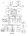
図1は、コンピュータシステム100の物理リソースを図示している。コンピュータ100は、データ、アドレス、制御信号を供給するプロセッサホストバス102と接続された、セントラルプロセッサ101を有している。プロセッサ101は、Pentium(登録商標)シリーズプロセッサ、K6プロセッサ、MIPS(登録商標)プロセッサ、PowerPC(登録商標)プロセッサ、またはALPHA(登録商標)プロセッサなどの、従来の汎用シングルチップまたはマルチチップマイクロプロセッサのいずれかであることができる。さらに、プロセッサ101は、ディジタルシグナルプロセッサまたはグラフィックプロセッサなどの、従来の特定用途マイクロプロセッサのいずれかであることもできる。マイクロプロセッサ101は、従来のアドレス、データ、プロセッサホストバス102と結合している制御ラインを有することができる。
【0015】
コンピュータ100は、RAMメモリコントローラ104を有するシステムコントローラ103を含むことができる。システムコントローラ103は、ホストバス102と接続し、ランダムアクセスメモリ105へのインターフェイスを提供することができる。システムコントローラ103は、ホストバスに、機能の橋渡しをする周辺バスも提供することができる。したがって、コントローラ103は、プロセッサホストバス102上の信号を主周辺バス110上の信号と互いに交換することを可能にする。例えば、周辺バス110は、Peripheral Component Interconnect(PCI)バス、Industry Standard Architecture(ISA)バス、またはMicro-Channelバスであることができる。さらに、コントローラ103は、ホストバス102と周辺バス103の間の、データバッファリングおよびデータ転送速度のマッチングを提供することができる。したがって、コントローラ103は、例えば64-bit 66MHzインタフェースおよび553Mb/sデータ転送速度を有するプロセッサ101が、データパスビット幅、クロック速度、データ転送速度の異なるデータパスを有するPCIバス110にインターフェイスすることを可能にする。
【0016】
例えば、ハードディスクドライブ150と結合しているブリッジコントローラ111に内蔵されたディスクコントローラ、ビデオディスプレイ115と結合しているビデオディスプレイコントローラ112などの付属デバイスは、周辺バス110と結合され、プロセッサ101によって制御される。コンピュータシステムは、インターネットおよびイントラネットなどのコンピュータシステムネットワークへ、ネットワークアダプタ114を介して接続することができる。データおよび情報は、そのような接続を通して送受信することができる。キーボードおよびマウスコントローラ113は、ISAバス120に接続されている。
【0017】
コンピュータ100は、基本的なコンピュータソフトウェアルーチンを格納する不揮発性ROMメモリ122も含むことができる。ROM122は、コンフィグレーションデータを格納するEEPROM(Electronically Erasable Programmable Read Only Memory)などの書換え可能なメモリを含むことができる。BIOSルーチン123は、ROM122に含められ、コンピュータの基本的な初期設定、システムの検査、入出力(I/O)サービスを提供することができる。BIOS123は、オペレーティングシステムをディスク113から「ブート」することができるルーチンも含むことができる。高水準オペレーティングシステムの例には、Microsoft Windows98(商標)、Windows NT(商標)、UNIX、LINUX、Apple Mac OS(商標)オペレーティングシステム、または他のオペレーティングシステムがある。
【0018】
オペレーティングシステムは、完全にRAMメモリ105にロードされるか、またはRAMメモリ105、ディスクドライブ記憶装置150、あるいはネットワークに位置する記憶装置の一部に含まれるようにすることもできる。オペレーティングシステムは、ソフトウェアアプリケーション、ソフトウェアシステムおよびソフトウェアシステムのツールを機能的に実行することを提供することができる。ソフトウェアの機能性によって、ビデオコンピュータディスプレイ115上に2次元(2−D)および3次元(3−D)モデルを提供するためにビデオディスプレイコントローラ112またはコンピュータシステム100の他のリソースにアクセスすることができる。
【0019】
図2を参照すると、CAD/CAM表示画面には、オブジェクトの3−Dモデルおよび階層ツリー240を含むことができる。階層ツリーにより、ユーザは異なる3−Dオブジェクトを選択することができる。また、CAD/CAM画面は、3−D描画の選択されたビューに対応した2−D生成の描画210を含むことができる。
【0020】
ディメンジョン生成フィルタパネル230も表示することができる。フィルタパネルは、ディメンジョンまたは他のドローデータ生成フィルタプロセスの制御を開始することのできるポップアップメニューまたは他のタイプのウィンドウであることができる。フィルタパネル230には、3−Dビュー220の2−D生成の描画210に関係するディメンジョンまたはコンストレイントのためのフィルタに関係する種々のオプションに対応する一連のチェックボックスまたは他のユーザ対話デバイスを含むことができる。
【0021】
フィルタパネルに含むことのできるオプションには、例えば、全てのディメンジョンを生成するオプション231、ワイヤフレームコンストレイントのスケッチを含むオプション232、3−Dのワイヤフレームコンストレイントを含むオプション233、測定されたディメンジョンを含むオプション234、およびデザインの許容誤差を含むオプション235を含むことができる。フィルタおよび一般の制御デバイスに関係する他のオプションは、ファルタパネルへプログラムすることもできる。ユーザの必要に応じて、アイコンまたは他のグラフィカルユーザ対話デバイスを使い、フィルタパネル機能をデスクトップから使用可能にすることもできる。
【0022】
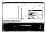
図3を参照すると、ステップバイステップ生成パネル、メニュー、または他のタイプのユーザ対話ウィンドウを、ディメンジョンの生成の制御を容易にするために使うことができる。ステップバイステップ生成パネルには、ディメンジョンの生成を制御するためのアイコンまたは他のユーザ対話デバイスを含むことができる。アイコンには、例えば、ディメンジョンの生成を開始する始動コマンドを発するための矢印アイコン311を含むことができる。単一の矢印などのシンボルは、ビデオまたはオーディオコントロールシステム上の操作ボタンにユーザが精通していることを利用することができる。同様に、二重矢印アイコン312を使って、ディメンジョンの生成プロセスを加速することができる。停止アイコン313を使って、ディメンジョンの生成を停止することができる。他のオプションには、二重バー314休止ボタンを含むことができる。棒グラフ330は、ディメンジョンの生成の進捗状態をグラフィカルに示すために使うことができる。さらに、制御には、ディメンジョンのビジュアライゼーション315の表示を含むことができる。増強したウィンドウを、タイムアウトまでの時間316の設定のために含めることもできる。タイムアウトは、ユーザがディメンジョン生成のステップの間に介入しなければならない時間幅を設定する。タイムアウト時間数がより大きければ、2−D生成の描画上に含まれる連続したディメンジョン生成の間に、より多くの時間を設けることができる。タイムアウト時間数がより低いならば、ディメンジョン生成のプロセスをより高速に進めることができる。
【0023】
図4を参照すると、ディメンジョンが3−Dモデル220から抽出され、2−D描画210上で視覚化することができる。ディメンジョンは、3−Dモデル410上でも視覚化することができる。2−Dモデル420上の対応するディメンジョンは、ユーザにより変更された、または現在のビューおよび/または3−Dモデルから削除されたドローデータの生成をユーザが選択する場合に、表示することができる。
【0024】
図5を参照すると、3−Dモデル220からドローデータを抽出し、2−Dモデル210にデータの生成をする際、ユーザは、生成プロセスを中断して、生成されているディメンジョンに変更を加えることができる。例えば、ディメンジョンが生成されるときに、ユーザは休止ボタン314を押すことができる。休止ボタン314は、タイムアウトクロックの動作を一時停止することができる。ディメンジョンの生成が中断している間、ユーザは、510および511のように生成されたディメンジョンの内容、外観、位置を変更することができる。変更には、例えば、生成されたコンストレイントのフォントまたはテキストを変更すること、太字、イタリック、下線または他のテキスト強調機能でテキストを強調すること、テキストの内容を変更すること、または生成されたディメンジョンのテキストの一部または全体を削除することを含めることができる。生成されたディメンジョンの位置も変更することができる。このように、ユーザは2−D描画の異なる領域にディメンジョンを配置することができる。
【0025】
図6を参照すると、ステップバイステップのディメンジョン生成には、特定のディメンジョンの削除も含むことができる。ディメンジョンの削除は、ディメンジョンがジェネレーティブドラフティングの他のビューで表示可能な場合でさえ、生成しないようにすることができる。このように、ユーザは効率的に、ジェネレーティブドラフティングの全てのビューから、望まないディメンジョンを取り除くことができる。2−D描画611から削除されたディメンジョンは、まだ3−Dモデル612で見ることができる。
【0026】
図7を参照すると、ステップバイステップパネル310上の早送り制御デバイス312は、ディメンジョンの生成を加速するために使うことができる。早送りボタン312の動作により、ユーザは単一のステップで、複数のディメンジョン、コンストレイント、またはドローデータを生成することが可能になる。一実施形態では、2つのコンストレイント710と711が、単一のステップで生成される。ステップはステップ棒グラフ330で追跡することができる。
【0027】
図8を参照すると、ユーザは、ディメンジョンの抽出およびドローデータ生成を停止したり、あるいはすべてのディメンジョンを生成プロセスが停止する時点で生成することができる。ディメンジョン生成プロセスが停止した後、生成ディメンジョン解析ウィンドウ800、または他のグラフィカル表示を使って、生成結果を表示することができる。生成ディメンジョン解析ウィンドウ800には、例えば3−Dモデル上のコンストレイントの数810、および2−D描画へ生成されたコンストレイントと関連したディメンジョンの数811を含むことができる。さらに、生成ディメンジョン解析ウィンドウ800には、生成されたディメンジョンと関連した3−Dモデル上のコンストレイント812、生成されたディメンジョンと関連したもの以外のコンストレイント813、あるいは除外されたコンストレイント814などの表示結果を制御するための、チェックボックスまたは他のユーザ対話デバイスを含むことができる。これらのオプションは、生成ディメンジョン解析ウィンドウのコンストレイント解析セクションの中に含められる。ディメンジョン解析セクションには、例えば、新しく生成されたディメンジョン用のチェックボックス815、生成されたディメンジョンの呼び出し用のチェックボックス816、他のディメンジョン用のチェックボックス817を含むことができる。生成されたディメンジョンに関する他のオプション、統計量、グラフィカル表示も、生成ディメンジョン解析メニュー800に含めることができる。
【0028】
図9を参照すると、一実施形態の例示的な流れ図には、例えば、ユーザがディメンジョンの生成の際に処理される細目を取り除くことができる、プログラム初期化ステージ910を含むことできる。細目には、例えば、平面と平面の2−D数字データ間の3−Dオフセットを含むコンストレイント3−DW、または、例えば倍率あるいは描画とそのビューなどの機能パラメータを含むことができる。ユーザは、半自動化モードでディメンジョンを生成することを選択することができる911。半自動化モードに対して応答「いいえ」を行うことで、ユーザは自動化モードを選択することができる912。自動化モードに対して続けて応答「いいえ」を行うことにより、ユーザはプログラムから出ることができる950。自動化モードに対して応答「はい」を行うと912、プログラムは全ての3−Dのコンストレイントを抽出して913、ドローデータを生成することができる914。
【0029】
半自動化モードに対して応答「はい」を行うことで911、ユーザはステップバイステップモードを指定することができる915。ユーザがステップバイステップモードで非稼働を選択する場合、タイムアウトの定義を行うよう要求される916。次いで、プログラムは3−Dビューからコンストレイントを抽出し917、コンストレイントがすでに処理されたかどうかの照会918に進むことができる。コンストレイントが処理されていない場合918、プログラムはドローデータを生成することができる919。ユーザが休止ボタンを押すことで割込む921前に、タイムアウトが満了する場合920、プログラムはループして、3−Dビューから他のコンストレイントを抽出することができる917。ユーザが休止ボタンまたはプロセスを休止するために他の対話デバイスを動作させる場合921、ユーザは生成されたドローデータを変更するよう促される922。ユーザは、生成されたドローデータで変更を行い923、修正形態を格納する924を行うことができる。修正形態を格納した後、あるいはユーザが生成されたドローデータの変更をしない場合922、ユーザは継続したいかどうかを促されることになる925。ユーザが継続を希望する場合925、ユーザは、自動化モードに分岐することができる926。ユーザが自動化モードに分岐しない場合926、プログラムはループして、3−Dビューから次のコンストレイントを抽出することができる917。ユーザが自動化モードに分岐することを選択した場合926、プログラムは出口950の前に残っているすべての3−Dのコンストレイントを抽出し913、ドローデータを生成するように進むことができる914。
【0030】
ステップバイステップ処理での進行を選択すると915、プログラムは3−Dビューからコンストレイントを抽出し927、そしてそのコンストレイントはすでに処理されたかどうかを照会することができる928。コンストレイントが処理されていない場合、プログラムはドローデータ929を生成することができる。コンストレイントがすでに処理されている場合、ユーザは生成されたドローデータを変更するよう促される930。ユーザが生成されたドローデータの変更をしない場合、システムはユーザが継続したいかどうかを照会することになる933。ユーザが継続を希望しないことを知らせると933、プログラムから出ることができる950。ユーザが継続を希望することを知らせると933、ユーザは自動化モード934を選択することができる。自動化モードを選択すると934、プログラムは、プログラムから出口950の前ですべてのコンストレイントを抽出し913、ドローデータを生成することができる914。自動化モードを選択しない場合934、プログラムはループして、次のコンストレイントを抽出し927、同様の方法で各コンストレイントを処理することができる。
【0031】
本発明は、ディジタル電子回路、またはコンピュータハードウェア、ファームウェア、ソフトウェア、あるいはそれらの組合せで実施することができる。本発明の装置は、プログラム可能なプロセッサによって実行するために、機械可読の記憶デバイスを実際に取り入れたコンピュータプログラム製品で実施することができ、本発明の方法のステップは、入力データに作用し、出力を生成することで本発明の機能を行うようにするための命令のプログラムを実行する、プログラム可能なプロセッサによって行うことができる。
【0032】
本発明は、データおよび命令を受け取り、データおよび命令を送るために結合される少なくとも1つのプログラム可能なプロセッサ、メモリ記憶システム、少なくとも1つの入力デバイス、そして少なくとも1つの出力デバイスを含む、プログラム可能なシステムで実行可能な、1つまたは複数のコンピュータプログラムで有効にに実施できる。各コンピュータプログラムは、高水準の手続きまたはオブジェクト指向のプログラミング言語、あるいは望む場合はアセンブリまたは機械言語で実施することができるが、どのような場合にも、言語はコンパイルまたは翻訳された言語である。
【0033】
通常、プロセッサは読出し専用メモリおよび/またはランダムアクセスメモリから命令およびデータを受け取ることができる。コンピュータプログラムの命令およびデータを、実際に実行するのに適した記憶デバイスは、例示的にEPROM、EEPROMなどの半導体メモリデバイスおよびフラッシュメモリデバイスを含むすべての形式の不揮発性メモリ、内部ハードディスクおよび取外し可能なディスクなどの磁気ディスク、光磁気ディスク、そしてCD−ROMディスクを含んでいる。前述のいずれも、特別に設計されたASIC(application-specific integrated circuits)によって補強し、あるいは内蔵することができる。
【0034】
本発明のいくつかの実施形態について記述してきた。本発明の趣旨および範囲を超えることなく、様々な修正形態が可能であることを理解されたい。したがって、他の実施態様は前述の特許請求の範囲内である。
【図面の簡単な説明】
【図1】本発明にかかるコンピュータシステムのブロック図である。
【図2】本発明におけるフィルタパネル付きのCAD/CAM表示の一例を示す図である。
【図3】本発明におけるステップバイステップパネル付きのCAD/CAM表示の一例を示す図である。
【図4】3−Dモデルから抽出され、2−D描画上に生成されたディメンジョンを示す図である。
【図5】ユーザにより変更されている生成されたディメンジョンを示す図である。
【図6】3−Dモデルの中に示された2−Dビューからディメンジョンを削除することを示す図である。
【図7】単一のステップで生成される多数のディメンジョンを示す図である。
【図8】本発明にかかる生成ディメンジョン解析ウィンドウの一例を示す図である。
【図9】本発明にかかるプログラミングの一例を示す流れ図である。
【符号の説明】
101 CPU
102 CPUバス
103 システムコントローラ
104 DRAMコントローラ
105 RAM
106 キャシュSRAM
110 周辺バス
111 ブリッジコントローラ
112 ビデオコントローラ
113 ディスク
114 ネットワークアダプタ
115 ビデオディスプレイ
120 ISAバス
121 キーボードコントローラ、マウスコントローラ
122 ROM
123 BIOS
124 オーディオ
125 マイク
126 スピーカ
127 マウス
128 キーボード
129 左ボタン
130 右ボタン
150 ハードディスクドライブ
210 2−Dモデル
220 3−Dモデル
230 フィルタパネル
231 全てのディメンジョンを生成
232 ワイヤフレームコンストレイントのスケッチ
233 3−Dのワイヤフレームコンストレイント
234 測定ディメンジョン
235 デザインの許容誤差
236、810 コンストレイントの数
240 階層ツリー
310 ステップバイステップパネル
311 矢印アイコン
312 二重矢印アイコン
313 停止アイコン
314 二重バー休止ボタン
315 ビジュアライゼーション
316 タイムアウトまでの持続時間
410,420 ディメンジョン
510、511 変更されたディメンジョン
611 削除された2−D描画
612 削除部分を有する3−Dモデル
710、711 コンストレイント
800 生成ディメンジョン解析ウィンドウ
811 生成されたコンストレイントと関連したディメンジョンの数
812 生成されたディメンジョンと関連した3−Dモデル上のコンストレイント
813 生成されたディメンジョンと関連したもの以外のコンストレイント
814 コンストレイントの除外
815 新しく生成されたディメンジョン用のチェックボックス
816 生成されたディメンジョンの呼び出し用のチェックボックス
817 他のディメンジョン用のチェックボックス[0001]
BACKGROUND OF THE INVENTION
The present invention relates to computer software utility programs, and more particularly to two-dimensional (3D) displaying different views of a three-dimensional (3-D) model using computer-aided design (CAD) and computer-aided production (CAM) systems. 2-D) relates to a method and apparatus for controlling the generation of dimensions or other draw data when creating a drawing.
[0002]
[Prior art]
When using CAD / CAM applications, it is often desirable to create two 2-D drawings that display different views of the 3-D model. Creating a 2-D view from a 3-D model is sometimes referred to as generative drafting. One difficulty associated with generative drafting processes is the selection of the desired drafting view. Once the user has selected an appropriate view, the user can move the system to a 2-D view with dimension constraints (eg, tolerance), or other available for 3-D models. Can be moved to the next data.
[0003]
In currently available CAD / CAM systems, the dimension and constraint transfers required by the user are automatically performed by the system according to a predefined set. The convention can define which dimensions or other constraints are shown in which view. Each dimension or other constraint is shown in one and only one view and can indicate where each is located. If the user is not satisfied with the presentation or location of one or more dimensions, it must wait for the entire transfer to complete before changes can be made to the displayed dimensions. Changes can be made with respect to the view selected in the process algorithm, the position on the view, or the way the dimensions were displayed. This automated process is generally acceptable for simple parts, but becomes more productive as the parts become more complex. If a large number of dimensions are transferred to one specific view and that view is obstructed by the dimension, a 2-D plan can be used to ensure that the dimension and other constraints are located where the user wants Fixing is quite difficult and can be annoying and time consuming.
[0004]
[Problems to be solved by the invention]
With the increasing need for increased productivity in the use of CAD / CAM systems, users have demanded more flexible dimension generation systems. This allows the user to decide if and when they want to change the position of dimensions and other constraints before all dimensions are shown in different views. Therefore, there is a need to provide the user with the ability to better control the dimension generation process.
[0005]
[Means for Solving the Problems]
Accordingly, the present invention provides a method and apparatus for controlling the generation of descriptive information, such as dimension generation, when generating a 2-D view of a graphical model defined by a computer. The user can operate in an automated mode that allows the CAD / CAM or other computer system to complete the transfer of all dimensions and other constraints, allowing the user to start modifying the drawing, and the user interrupts the transfer process An option is provided to select a semi-automated mode of operation that is capable of modifying the data being transferred up to the point of interruption.
[0006]
In one embodiment, the user may further be provided with options for manual control dimensions and constraint generation. Using manual control, the process moves from one step to the next under the control of the user. In a preferred embodiment, the dimension or draw data can be generated in a semi-automated mode of operation. By using the semi-automated mode, the user can choose to pause the production process. During the pause, the user can modify the draw data that needs to be modified, or interrupt the process to perform other tasks. The need to perform other tasks means that if other views are added to the drawing, some dimensions or other constraints already transferred by the system will better find their location. May result from user perception. The ability to create new views before the entire transfer process is complete can result in increased productivity. In a preferred embodiment, the system resumes from the beginning of the process, allowing all changes entered by the user prior to the process to stop or pause.
[0007]
In another aspect of the invention, the semi-automated mode of operation can take into account a user defined filter. The filter thereby removes a 3-D model draw data item or a 2-D drawing specific view from the generation process.
[0008]
The present invention can also include a software-controlled method with steps for creating a two-dimensional view of a computer-defined graphical model, such as a three-dimensional model. A method of software control generates a draw data item, such as a dimension or constraint, associated with a component of a 2D view and forms a user interface for controlling the addition of the draw data item to the 2D view. Can do. Draw data items can be added to the two-dimensional view in response to operation of a user interaction device with a user interface.
[0009]
In general, in another aspect of the invention, draw data items can be semi-automatically added to a two-dimensional view in response to the expiration of a predetermined timeout period when there is no interrupt user action. Interrupt operations may include the operation of a pause button or other user interaction device such as a check box, yes / no area, or other area of the screen in response to a button click on the pointing device or other user control. it can.
[0010]
In yet another aspect, dimension generation can redo changes to draw data or deletes draw data. Deletion can also be implemented so that deleted data is removed from the next view of the object. In one embodiment, the user can stop the generation of draw data by operation of the user-initiated device. When production is stopped, the user can also create additional two-dimensional views. Changes and modifications to the draw data are stored and can be played back in the two-dimensional view that is formed thereafter.
[0011]
In other embodiments, the user can allow the program to automatically generate additional draw data following a change to a particular draw data item.
[0012]
The present invention can also implement a computer system, a programmed computer, a computer program resident on a computer readable medium or a method for interacting with a computer and implementing the concepts described above.
[0013]
The details of one or more embodiments of the invention are set forth in the accompanying drawings and the description below. Implementations provide benefits such as helping the user's customized dimensions and other relevant data in a two-dimensional view of the model. Other features, objects, and advantages of the invention will be apparent from the description and drawings, and from the claims.
[0014]
DETAILED DESCRIPTION OF THE INVENTION
FIG. 1 illustrates the physical resources of the
[0015]
The
[0016]
For example, an attached device such as a disk controller incorporated in the
[0017]
[0018]
The operating system may be fully loaded into the
[0019]
Referring to FIG. 2, the CAD / CAM display screen may include a 3-D model of objects and a
[0020]
A dimension
[0021]
Options that can be included in the filter panel include, for example, an
[0022]
Referring to FIG. 3, a step-by-step generation panel, menu, or other type of user interaction window can be used to facilitate control of dimension generation. The step-by-step generation panel can include icons or other user interaction devices for controlling the generation of dimensions. The icon can include, for example, an
[0023]
With reference to FIG. 4, dimensions can be extracted from the 3-
[0024]
Referring to FIG. 5, when draw data is extracted from the 3-
[0025]
Referring to FIG. 6, step-by-step dimension generation can include deletion of a specific dimension. Deleting a dimension can prevent it from being generated even if the dimension can be displayed in other views of generative drafting. In this way, the user can efficiently remove unwanted dimensions from all views of generative drafting. The dimension deleted from the 2-
[0026]
Referring to FIG. 7, the fast-
[0027]
Referring to FIG. 8, the user can stop dimension extraction and draw data generation, or generate all dimensions when the generation process stops. After the dimension generation process stops, the generation results can be displayed using the generation
[0028]
Referring to FIG. 9, an exemplary flow diagram of one embodiment can include a
[0029]
By responding “911” to the
[0030]
Upon selecting 915 step by step processing, the program extracts the constraint from the 3-
[0031]
The invention can be implemented in digital electronic circuitry, or computer hardware, firmware, software, or combinations thereof. The apparatus of the present invention can be implemented in a computer program product that actually incorporates a machine-readable storage device for execution by a programmable processor, and the method steps of the present invention operate on input data; It can be performed by a programmable processor that executes a program of instructions for generating output to perform the functions of the present invention.
[0032]
The present invention is a programmable including at least one programmable processor, a memory storage system, at least one input device, and at least one output device coupled to receive and send data and instructions. It can be effectively implemented with one or more computer programs executable on the system. Each computer program can be implemented in a high-level procedural or object-oriented programming language, or assembly or machine language if desired, but in any case the language is a compiled or translated language.
[0033]
Generally, a processor can receive instructions and data from a read only memory and / or a random access memory. Storage devices suitable for actually executing computer program instructions and data include, for example, all forms of non-volatile memory, internal hard disks and removable devices, including semiconductor memory devices such as EPROM, EEPROM and flash memory devices. This includes magnetic disks such as new disks, magneto-optical disks, and CD-ROM disks. Any of the foregoing can be reinforced or incorporated by specially designed application-specific integrated circuits (ASICs).
[0034]
A number of embodiments of the invention have been described. It should be understood that various modifications can be made without departing from the spirit and scope of the invention. Accordingly, other embodiments are within the scope of the foregoing claims.
[Brief description of the drawings]
FIG. 1 is a block diagram of a computer system according to the present invention.
FIG. 2 is a diagram showing an example of a CAD / CAM display with a filter panel according to the present invention.
FIG. 3 is a diagram showing an example of a CAD / CAM display with a step-by-step panel according to the present invention.
FIG. 4 is a diagram showing dimensions extracted from a 3-D model and generated on 2-D drawing.
FIG. 5 is a diagram showing generated dimensions that have been changed by a user.
FIG. 6 is a diagram illustrating deleting dimensions from the 2-D view shown in the 3-D model.
FIG. 7 shows a number of dimensions generated in a single step.
FIG. 8 is a diagram showing an example of a generated dimension analysis window according to the present invention.
FIG. 9 is a flowchart showing an example of programming according to the present invention.
[Explanation of symbols]
101 CPU
102 CPU bus
103 System controller
104 DRAM controller
105 RAM
106 cache SRAM
110 Peripheral bus
111 Bridge controller
112 Video controller
113 discs
114 Network adapter
115 video display
120 ISA bus
121 Keyboard controller, mouse controller
122 ROM
123 BIOS
124 audio
125 microphone
126 Speaker
127 mouse
128 keyboard
129 Left button
130 Right button
150 hard disk drive
210 2-D Model
220 3-D model
230 Filter panel
231 Generate all dimensions
232 Sketch of wireframe constraints
233 3-D wireframe constraints
234 Measurement dimensions
235 Design tolerance
236, 810 Number of constraints
240 Hierarchical tree
310 Step-by-step panel
311 arrow icon
312 double arrow icon
313 stop icon
314 Double bar pause button
315 Visualization
316 Duration until timeout
410,420 Dimensions
510, 511 Changed dimensions
611 Deleted 2-D drawing
612 3-D model with deleted part
710, 711 Constraint
800 Generation dimension analysis window
811 Number of dimensions associated with generated constraints
812 Constraints on the 3-D model associated with the generated dimension
813 Constraints other than those associated with the generated dimension
814 Constraint exclusion
815 Check box for newly created dimension
816 Check box for calling the generated dimension
817 Check boxes for other dimensions
Claims (9)
前記3次元グラフィカルモデルに基づく2次元ビューに、前記プロセッサが、抽出された記述情報から前記2次元ビューのディスプレイに表示される構成要素に関連した記述情報を生成するステップと、
前記表示される構成要素に関連した記述情報の前記2次元ビューへの追加を制御するための第1のユーザインターフェイスを、前記プロセッサが前記ディスプレイに表示するステップと、
前記第1のユーザインターフェイスから入力されたユーザ入力データに応じて、前記プロセッサが、前記表示される構成要素に関連した記述情報の中から前記2次元ビューに追加されるべき第1のサブセットを選択して、選択された第1のサブセットを前記2次元ビューに追加するステップと、
記述情報の生成を割込み動作なしに行う自動化モードと、前記割込み動作を受け入れて行う半自動化モードとを選択するための第2のユーザインターフェイスを表示するステップと、
前記半自動化モードが選択されると、記述情報を生成するプロセスを休止させ、前記プロセスが休止している間に、前記プロセッサが、ユーザ入力データに応じて、記述情報を変更するステップとを備え、
前記2次元ビューに追加されるべき前記第1のサブセットは、前記2次元ビューの表示として前記ディスプレイに表示されることを特徴とするCAD/CAMにおけるソフトウェア制御方法。A processor extracting, from a computer-defined three-dimensional graphical model stored in memory, descriptive information that is a dimension or constraint of the three-dimensional graphical model ;
Wherein the 3-dimensional based rather two-dimensional view to a graphical model, and generating the processor, descriptive information relating from the extracted written information components to be displayed on the display of the 2-dimensional view,
The processor displaying on the display a first user interface for controlling the addition of descriptive information associated with the displayed component to the two-dimensional view;
In response to user input data input from the first user interface, the processor selects a first subset to be added to the two-dimensional view from descriptive information associated with the displayed component. Adding the selected first subset to the two-dimensional view ;
Displaying a second user interface for selecting an automation mode for generating descriptive information without an interrupt operation and a semi-automation mode for accepting the interrupt operation;
When the semi-automated mode is selected, the process of generating description information is paused, and the processor changes the description information according to user input data while the process is paused. ,
The software control method in CAD / CAM, wherein the first subset to be added to the two-dimensional view is displayed on the display as a display of the two-dimensional view.
前記プロセッサが、次の2次元ビューの生成の間、前記記述情報の第2のサブセットが、前記生成された2次元ビューに表示されないようにするステップと
をさらに含むことを特徴とする請求項1に記載のCAD/CAMにおけるソフトウェア制御方法。The processor detecting user input data indicative of a second subset of the description information that is not added to the two-dimensional view;
The processor further comprises: preventing a second subset of the description information from being displayed in the generated two-dimensional view during generation of the next two-dimensional view. Software control method in CAD / CAM as described in 1.
Applications Claiming Priority (2)
| Application Number | Priority Date | Filing Date | Title |
|---|---|---|---|
| US09/329,923 US6918095B1 (en) | 1999-06-10 | 1999-06-10 | Dimension generation filter and analysis |
| US09/329923 | 1999-06-10 |
Publications (2)
| Publication Number | Publication Date |
|---|---|
| JP2001052042A JP2001052042A (en) | 2001-02-23 |
| JP3939901B2 true JP3939901B2 (en) | 2007-07-04 |
Family
ID=23287600
Family Applications (1)
| Application Number | Title | Priority Date | Filing Date |
|---|---|---|---|
| JP2000173621A Expired - Lifetime JP3939901B2 (en) | 1999-06-10 | 2000-06-09 | Method and system for controlling dimension generation or other draw data |
Country Status (6)
| Country | Link |
|---|---|
| US (1) | US6918095B1 (en) |
| EP (1) | EP1059616B1 (en) |
| JP (1) | JP3939901B2 (en) |
| AT (1) | ATE547777T1 (en) |
| CA (1) | CA2305066C (en) |
| DE (1) | DE1059616T1 (en) |
Families Citing this family (4)
| Publication number | Priority date | Publication date | Assignee | Title |
|---|---|---|---|---|
| GB0228973D0 (en) * | 2002-12-12 | 2003-01-15 | Univ Aston | System and method for coding and retrieval of a CAD drawing from a database |
| JP4547990B2 (en) * | 2004-05-25 | 2010-09-22 | 富士ゼロックス株式会社 | Information processing apparatus and information processing program |
| US7561996B2 (en) * | 2006-01-13 | 2009-07-14 | Chrysler Llc | Automated dimensional drawing generating apparatus |
| US20150347366A1 (en) * | 2014-05-28 | 2015-12-03 | Siemens Product Lifecycle Management Software Inc. | Creation of associative 3d product documentation from drawing annotation |
Family Cites Families (26)
| Publication number | Priority date | Publication date | Assignee | Title |
|---|---|---|---|---|
| US5202961A (en) | 1990-06-08 | 1993-04-13 | Apple Computer, Inc. | Sequential information controller |
| BE1003143A6 (en) | 1991-04-30 | 1991-12-10 | Ardill Robert Henry | APPARATUS FOR MEASURING MILK IN A DISCONTINUOUS MANNER. |
| US5603318A (en) * | 1992-04-21 | 1997-02-18 | University Of Utah Research Foundation | Apparatus and method for photogrammetric surgical localization |
| JP3221086B2 (en) * | 1992-09-17 | 2001-10-22 | 株式会社日立製作所 | Heterogeneous mechanical parts composite mechanism design system |
| US5548706A (en) | 1992-09-29 | 1996-08-20 | Fujitsu Limited | CAD system with parallel dimension-line editing function |
| JP3038521B2 (en) * | 1993-04-02 | 2000-05-08 | 株式会社日立製作所 | Product drawing creation device |
| US5548707A (en) | 1993-11-09 | 1996-08-20 | Adra Systems, Inc. | Method and system for design and drafting |
| US5544291A (en) * | 1993-11-10 | 1996-08-06 | Adobe Systems, Inc. | Resolution-independent method for displaying a three dimensional model in two-dimensional display space |
| US5687305A (en) * | 1994-03-25 | 1997-11-11 | General Electric Company | Projection of images of computer models in three dimensional space |
| JP3333319B2 (en) * | 1994-06-03 | 2002-10-15 | 三菱電機株式会社 | 2D and 3D integrated CAD system |
| JPH08287288A (en) * | 1995-03-24 | 1996-11-01 | Internatl Business Mach Corp <Ibm> | Plurality of side annotations interactive three-dimensional graphics and hot link |
| US5729673A (en) * | 1995-04-07 | 1998-03-17 | Avid Technology, Inc. | Direct manipulation of two-dimensional moving picture streams in three-dimensional space |
| JP3245336B2 (en) * | 1995-09-29 | 2002-01-15 | 富士通株式会社 | Modeling method and modeling system |
| EP1460604A3 (en) * | 1996-04-16 | 2006-11-02 | Xanavi Informatics Corporation | Map display device, navigation device and map display method |
| US6308144B1 (en) * | 1996-09-26 | 2001-10-23 | Computervision Corporation | Method and apparatus for providing three-dimensional model associativity |
| US6466239B2 (en) * | 1997-01-24 | 2002-10-15 | Sony Corporation | Method and apparatus for editing data used in creating a three-dimensional virtual reality environment |
| IL120136A0 (en) * | 1997-02-03 | 1997-06-10 | Yissum Res Dev Co | Synthesizing virtual two dimensional images of three dimensional space from a collection of real two dimensional images |
| US6124864A (en) * | 1997-04-07 | 2000-09-26 | Synapix, Inc. | Adaptive modeling and segmentation of visual image streams |
| US5857032A (en) * | 1997-04-25 | 1999-01-05 | General Electric Company | System and method for measuring and monitoring three-dimensional shaped objects |
| US6492986B1 (en) * | 1997-06-02 | 2002-12-10 | The Trustees Of The University Of Pennsylvania | Method for human face shape and motion estimation based on integrating optical flow and deformable models |
| US5990897A (en) * | 1997-09-12 | 1999-11-23 | Hanratty; Patrick J. | Methods for automatically generating a three-dimensional geometric solid from two-dimensional view sets including automatic segregation of open, closed and disjoint curves into views using their center of gravity |
| US6542937B1 (en) * | 1998-02-27 | 2003-04-01 | Amada Company, Limited | Apparatus and method for transferring and editing sheet metal part data |
| US6137491A (en) * | 1998-06-05 | 2000-10-24 | Microsoft Corporation | Method and apparatus for reconstructing geometry using geometrically constrained structure from motion with points on planes |
| US6281903B1 (en) * | 1998-12-04 | 2001-08-28 | International Business Machines Corporation | Methods and apparatus for embedding 2D image content into 3D models |
| US6771260B1 (en) * | 1999-12-13 | 2004-08-03 | Amada Company, Limited | Sketcher |
| US6775581B2 (en) * | 2001-03-14 | 2004-08-10 | Delphi Technologies, Inc. | Horizontally-structured CAD/CAM modeling for virtual concurrent product and process design |
-
1999
- 1999-06-10 US US09/329,923 patent/US6918095B1/en not_active Expired - Lifetime
-
2000
- 2000-04-12 CA CA002305066A patent/CA2305066C/en not_active Expired - Lifetime
- 2000-05-19 DE DE1059616T patent/DE1059616T1/en active Pending
- 2000-05-19 EP EP00401390A patent/EP1059616B1/en not_active Expired - Lifetime
- 2000-05-19 AT AT00401390T patent/ATE547777T1/en active
- 2000-06-09 JP JP2000173621A patent/JP3939901B2/en not_active Expired - Lifetime
Also Published As
| Publication number | Publication date |
|---|---|
| DE1059616T1 (en) | 2001-10-25 |
| ATE547777T1 (en) | 2012-03-15 |
| US6918095B1 (en) | 2005-07-12 |
| EP1059616A2 (en) | 2000-12-13 |
| CA2305066A1 (en) | 2000-12-10 |
| EP1059616B1 (en) | 2012-02-29 |
| CA2305066C (en) | 2009-12-22 |
| EP1059616A3 (en) | 2004-05-26 |
| JP2001052042A (en) | 2001-02-23 |
Similar Documents
| Publication | Publication Date | Title |
|---|---|---|
| US6219049B1 (en) | Mate inferencing | |
| JP2732557B2 (en) | Method and data processing system for changing function of GUI | |
| JP3739999B2 (en) | 3D graphical manipulator | |
| US8896549B2 (en) | Method and system for duplicating an object using a touch-sensitive display | |
| JP4717116B2 (en) | Method, program, and data processing system for changing shape of display object | |
| US6717587B2 (en) | Positioning and alignment aids for shape objects having authorable behaviors and appearances | |
| EP0745927B1 (en) | Method of and editing system for setting tool button | |
| EP1071014B1 (en) | Adding code in an application during runtime to enrich object behavior | |
| CN110795796A (en) | Designing an object representing a 3D modeling of a mechanical structure | |
| JP3939901B2 (en) | Method and system for controlling dimension generation or other draw data | |
| US7554544B2 (en) | Just-in-time user interface layout | |
| JP3517643B2 (en) | Join estimation | |
| US8392151B1 (en) | Preview of an object in graphical modeling environments | |
| JP2000187547A (en) | Device and method for controlling scroll | |
| TW507139B (en) | Fast editing and selecting method for multi-media object attributes and the devices thereof | |
| US7703038B1 (en) | Methods and apparatus for creating a quick canvas | |
| JP2003281206A (en) | Design support device | |
| JPH07262345A (en) | Multimedia presentation editing method | |
| JP4084132B2 (en) | Drawing support method, drawing support device, and drawing support program | |
| Freitag et al. | Tiquid: creating continuous transitions for multi-touch interactions | |
| CN115454408A (en) | Graphical programming method and device of track, electronic device and storage medium | |
| JPH1021062A (en) | Device and method for visual programming | |
| JPS63104127A (en) | Computer system | |
| JP2002140112A (en) | Display for monitoring operation | |
| JP2006079170A (en) | Medium data processing procedure edition method, device, and programs |
Legal Events
| Date | Code | Title | Description |
|---|---|---|---|
| A601 | Written request for extension of time |
Free format text: JAPANESE INTERMEDIATE CODE: A601 Effective date: 20031226 |
|
| A602 | Written permission of extension of time |
Free format text: JAPANESE INTERMEDIATE CODE: A602 Effective date: 20040107 |
|
| A521 | Request for written amendment filed |
Free format text: JAPANESE INTERMEDIATE CODE: A523 Effective date: 20040330 |
|
| A02 | Decision of refusal |
Free format text: JAPANESE INTERMEDIATE CODE: A02 Effective date: 20040525 |
|
| RD13 | Notification of appointment of power of sub attorney |
Free format text: JAPANESE INTERMEDIATE CODE: A7433 Effective date: 20040825 |
|
| A521 | Request for written amendment filed |
Free format text: JAPANESE INTERMEDIATE CODE: A821 Effective date: 20040825 |
|
| A521 | Request for written amendment filed |
Free format text: JAPANESE INTERMEDIATE CODE: A523 Effective date: 20040922 |
|
| A911 | Transfer to examiner for re-examination before appeal (zenchi) |
Free format text: JAPANESE INTERMEDIATE CODE: A911 Effective date: 20041101 |
|
| A912 | Re-examination (zenchi) completed and case transferred to appeal board |
Free format text: JAPANESE INTERMEDIATE CODE: A912 Effective date: 20041119 |
|
| A521 | Request for written amendment filed |
Free format text: JAPANESE INTERMEDIATE CODE: A523 Effective date: 20070207 |
|
| A61 | First payment of annual fees (during grant procedure) |
Free format text: JAPANESE INTERMEDIATE CODE: A61 Effective date: 20070329 |
|
| R150 | Certificate of patent or registration of utility model |
Free format text: JAPANESE INTERMEDIATE CODE: R150 Ref document number: 3939901 Country of ref document: JP Free format text: JAPANESE INTERMEDIATE CODE: R150 |
|
| FPAY | Renewal fee payment (event date is renewal date of database) |
Free format text: PAYMENT UNTIL: 20110406 Year of fee payment: 4 |
|
| R250 | Receipt of annual fees |
Free format text: JAPANESE INTERMEDIATE CODE: R250 |
|
| FPAY | Renewal fee payment (event date is renewal date of database) |
Free format text: PAYMENT UNTIL: 20120406 Year of fee payment: 5 |
|
| R250 | Receipt of annual fees |
Free format text: JAPANESE INTERMEDIATE CODE: R250 |
|
| FPAY | Renewal fee payment (event date is renewal date of database) |
Free format text: PAYMENT UNTIL: 20130406 Year of fee payment: 6 |
|
| R250 | Receipt of annual fees |
Free format text: JAPANESE INTERMEDIATE CODE: R250 |
|
| FPAY | Renewal fee payment (event date is renewal date of database) |
Free format text: PAYMENT UNTIL: 20130406 Year of fee payment: 6 |
|
| FPAY | Renewal fee payment (event date is renewal date of database) |
Free format text: PAYMENT UNTIL: 20140406 Year of fee payment: 7 |
|
| R250 | Receipt of annual fees |
Free format text: JAPANESE INTERMEDIATE CODE: R250 |
|
| R250 | Receipt of annual fees |
Free format text: JAPANESE INTERMEDIATE CODE: R250 |
|
| R250 | Receipt of annual fees |
Free format text: JAPANESE INTERMEDIATE CODE: R250 |
|
| R250 | Receipt of annual fees |
Free format text: JAPANESE INTERMEDIATE CODE: R250 |
|
| R250 | Receipt of annual fees |
Free format text: JAPANESE INTERMEDIATE CODE: R250 |
|
| R250 | Receipt of annual fees |
Free format text: JAPANESE INTERMEDIATE CODE: R250 |
|
| R250 | Receipt of annual fees |
Free format text: JAPANESE INTERMEDIATE CODE: R250 |
|
| R250 | Receipt of annual fees |
Free format text: JAPANESE INTERMEDIATE CODE: R250 |
|
| EXPY | Cancellation because of completion of term |