JP3934353B2 - Image processing apparatus, recording medium, and program - Google Patents
Image processing apparatus, recording medium, and program Download PDFInfo
- Publication number
- JP3934353B2 JP3934353B2 JP2001048687A JP2001048687A JP3934353B2 JP 3934353 B2 JP3934353 B2 JP 3934353B2 JP 2001048687 A JP2001048687 A JP 2001048687A JP 2001048687 A JP2001048687 A JP 2001048687A JP 3934353 B2 JP3934353 B2 JP 3934353B2
- Authority
- JP
- Japan
- Prior art keywords
- image
- halftone dot
- halftone
- pixel
- processing apparatus
- Prior art date
- Legal status (The legal status is an assumption and is not a legal conclusion. Google has not performed a legal analysis and makes no representation as to the accuracy of the status listed.)
- Expired - Fee Related
Links
Images


Description
【0001】
【発明の属する技術分野】
本発明は、デジタル画像を処理する画像処理技術に関し、特に、網点画像領域と文字領域とを有するデジタル画像を処理する画像処理技術に関する。
【0002】
【関連技術】
スキャナなどの画像読取装置を用いて入力した画像をさらに出力する場合が存在する。
【0003】
このような場合において、入力されたデジタル画像の解像度が比較的大きく、かつ、出力機器の解像度が比較的小さい場合(例えば133線以上の線数を有する網点画像をそれよりも小さな線数(例えば106線)を有する画像として出力する場合)には、階調のつぶれやトーンジャンプが発生することがある。
【0004】
このような状況を回避するためには、入力画像に対してぼかし処理を施した後さらに網点数を変換する処理(以下では、「スクリーン線数変換処理」とも称する)を施すことが考えられる。なお、ぼかし処理を行わずに網点数を変換する処理のみを行うと、新旧の網点線数を有するスクリーンパターンが周期的な干渉状態を生じるためモアレが発生する。したがって、これを回避するため、スクリーン線数変化処理において、ぼかし処理を行うことが必要になる。
【0005】
【発明が解決しようとする課題】
しかしながら、網点画像領域と文字領域との両領域を有するデジタル画像に対して上記のぼかし処理を含むスクリーン線数変換処理を施すと、文字領域内の文字がぼけてしまうという事態が生じる。図28は、網点画像領域SRと文字領域CRとを有する処理対象画像の一例を示す図であり、図29は、図28の左上側の文字部分を拡大して示す図である。そして、図30は、この処理対象画像に対して上記のスクリーン線数変換処理を施した画像である。図30には、スクリーン線数変換処理の結果、文字がぼけてしまっている状況が示されている。
【0006】
この現象は、性質が互いに異なる両領域(網点画像領域および文字領域)に対して同一の処理を行うことに起因する問題である。すなわち、デジタル画像内における網点画像領域と文字領域とを分離することが要請されている。
【0007】
また、上記のような網点画像領域と文字領域とを分離することは、スクリーン線数変換処理を行う際のみならず、両領域を有するデジタル画像処理における様々な処理を行う際に要請される技術である。
【0008】
そこで、本発明は前記問題点に鑑み、デジタル画像内における網点画像領域と文字領域とを分離することが可能な技術を提供することを目的とする。
【0009】
【課題を解決するための手段】
上記目的を達成するため、請求項1に記載の画像処理装置は、デジタル画像を取得するデジタル画像取得手段と、前記デジタル画像の網点情報として網点線数と網点角度とを取得する網点情報取得手段と、前記デジタル画像の解像度と前記網点線数と前記網点角度とに基づいて、所定の網点と4つの隣接網点のそれぞれとを結ぶ4つのベクトルを求める手段と、注目画素から前記4つのベクトルのそれぞれに相当するベクトル量だけ移動させた4つの近傍画素を選択する手段と、前記注目画素と前記4つの近傍画素のそれぞれとの差分の絶対値を加算した加算結果を求め、前記加算結果の方が所定値より小さい場合に前記注目画素が前記網点画像領域にあると判定し、前記加算結果の方が所定値より大きい場合に前記注目画素が前記文字領域にあると判定することによって前記注目画素が網点画像領域内の画素であるか文字領域内の画素であるかについての判定処理を行う判定手段と、前記判定処理の結果に基づいて前記網点画像領域の画素と前記文字領域の画素とが異なる階調値を有する2値画像であるマスク画像を生成するマスク画像生成手段と、前記デジタル画像についてぼかし処理を行うぼかし処理手段と、前記ぼかし処理によって得られた画像を前記再網点化する再網点処理を行う再網点化処理手段と、前記マスク画像を用いて前記網点画像領域にあると判定される画素については前記ぼかし処理および前記再網点化処理を施した結果を採用し、前記文字領域にあると判定される画素については前記ぼかし処理および前記再網点化処理を施さない結果を採用することによって合成画像を生成する合成手段と、を備えることを特徴とする。
【0011】
請求項2に記載の画像処理装置は、請求項1に記載の画像処理装置において、前記デジタル画像に対する平滑化処理を行う手段、をさらに備え、前記判定手段は、前記平滑化処理が施された画像について前記判定処理を行うことを特徴とする。
【0012】
請求項3に記載の画像処理装置は、請求項1または請求項2に記載の画像処理装置において、前記判定手段は、前記注目画素およびその周辺画素を含む領域に対するメディアンフィルタ処理を用いて、当該判定処理における判定結果を修正することを特徴とする。
【0013】
請求項4に記載の画像処理装置は、請求項1ないし請求項3のいずれかに記載の画像処理装置において、前記判定手段は、文字領域として判定される領域を拡張する太らせ処理を用いて、前記判定結果を修正することを特徴とする。
【0014】
請求項5に記載の画像処理装置は、請求項1ないし請求項4のいずれかに記載の画像処理装置において、前記網点情報取得手段は、前記網点情報を入力する網点情報入力手段を有し、当該網点情報入力手段を用いて入力された情報を前記網点情報として取得することを特徴とする。
【0015】
請求項6に記載の画像処理装置は、請求項1ないし請求項5のいずれかに記載の画像処理装置において、前記網点情報取得手段は、前記網点情報を前記デジタル画像から抽出する網点情報抽出手段を有し、当該網点情報抽出手段によって抽出された情報を前記網点情報として取得することを特徴とする。
【0016】
請求項7に記載の画像処理装置は、請求項1ないし請求項6のいずれかに記載の画像処理装置において、前記判定処理を行うべき領域を指定する領域指定手段、をさらに備えることを特徴とする。
【0017】
請求項8に記載の画像処理装置は、請求項7に記載の画像処理装置において、前記網点情報取得手段は、前記領域指定手段により指定された領域ごとに前記網点情報を取得することを特徴とする。
【0018】
請求項9に記載の画像処理装置は、請求項1ないし請求項8のいずれかに記載の画像処理装置において、前記網点情報抽出手段は、前記網点情報を所定のブロック単位で抽出することを特徴とする。
【0020】
請求項10に記載の記録媒体は、コンピュータが有するCPUとメモリとを使用することにより、前記コンピュータを、請求項1ないし請求項9のいずれかに記載の画像処理装置として機能させるためのプログラムを記録したコンピュータ読み取り可能な記録媒体であることを特徴とする。
【0021】
請求項11に記載のプログラムは、コンピュータが有するCPUとメモリとを使用することにより、前記コンピュータを、請求項1ないし請求項9のいずれかに記載の画像処理装置として機能させるためのプログラムであることを特徴とする。
【0022】
【発明の実施の形態】
以下、本発明の実施形態を図面に基づいて説明する。
【0023】
<A.構成>
図1は、本発明の実施形態に係る画像処理装置1のハードウエア構成を表す概念図である。図1に示すように、画像処理装置1は、CPU2、半導体メモリおよびハードディスクなどを含む記憶部3、各種の記録媒体から情報を読み出すメディアドライブ4、モニタなどを含む表示部5、キーボートおよびマウスなどを含む入力部6、他の機器との通信を行う通信部7を備えるコンピュータシステム(以下、単に「コンピュータ」とも称する)によって構成されている。CPU2は、バスラインBLおよび入出力インターフェースIFを介して、記憶部3、メディアドライブ4、表示部5、入力部6、通信部7などに接続されている。また、メディアドライブ4は、CD−ROM、DVD(Digital Versatile Disk)、フレキシブルディスクなどの可搬性の記録媒体9からその中に記録されている情報を読み出す。
【0024】
このコンピュータは、記録媒体9に記録されたソフトウエアプログラム(以下、単に「プログラム」とも称する)を読み込み、そのプログラムをCPU2等を用いて実行することによって、後述するような各種の動作を実現する画像処理装置1として機能する。なお、各機能を有するプログラムは、記録媒体9を介して供給(ないし配給)される場合に限定されず、LANやインターネットなどのネットワーク(通信回線)および通信部7を介して、このコンピュータに対して供給(ないし配給)されてもよい。
【0025】
このように、この画像処理装置1は、コンピュータにおいてソフト的に構築される。
【0026】
図2は、画像処理装置1の機能ブロック図である。図2に示すように、画像処理装置1は、スキャナなどの画像読取装置70から入力されたデジタル画像に対する画像処理を行い、印刷出力装置などの画像出力装置80に対してその処理結果としての画像を出力する。
【0027】
画像処理装置1は、処理対象となる領域を指定する領域指定部12と、網点情報を入力する網点情報入力部20と、所定の網点から4方向の隣接網点へと向かう4つのベクトルを求める4方向ベクトル算出部40と、文字網点分離処理部50と、スクリーン線数変換処理部60とを備えている。また、文字網点分離処理部50は、平滑化処理部51、差分値加算処理部52、二値化処理部53、メディアンフィルタ処理部54、および太らせ処理部55を有しており、スクリーン線数変換処理部60は、ぼかし等処理部61および合成処理部62を有している。これらの各部は、所定のプログラムを実行することによってコンピュータにおいてソフト的に構築される。
【0028】
この画像処理装置1は、文字網点分離処理部50などを用いることによって、各注目画素が網点画像領域内の画素であるか文字領域内の画素であるかを判定することができ、また、その判定結果を利用してスクリーン線数変換処理部60などを用いてスクリーン線数変換処理を行うことが可能である。各処理部の詳細動作等については、後述する。
【0029】
<B.動作>
<概略動作>
図3は、画像処理装置1におけるスクリーン線数変換処理の動作を示すフローチャートである。図3を参照しながら、このスクリーン線数変換処理について説明する。
【0030】
まず、ステップSP10において、画像処理装置1は、画像読取装置70などからのデジタル画像を取得する。図4に示すように、このデジタル画像には、網点画像領域SRと文字領域CRとが含まれている。また、このデジタル画像は、たとえば、二値画像として取得される。ここでは、以下の処理において多階調化することが好ましいので、この時点において、二値画像の各画素の階調値0,1のそれぞれを便宜的に0,255にあらかじめ変換しておく。後述の各処理によって、この二値画像は、256段階の階調値を有する多値画像に実際に変換される。
【0031】
また、画像処理装置1の操作者(オペレータ)は、必要に応じて、ステップSP30,SP40(後述)の処理を行うべき領域を手動で指定するようにしても良い。言い換えれば、処理対象領域をトリミングによって指定することができる。このようにして処理対象領域を限定することによって、処理の高速化を図ることが可能である。
【0032】
具体的には、図4に示すように、画面に表示されるデジタル画像Pにおいて、網点画像領域SRを含む領域DRを処理対象領域として指定することができる。また、この指定領域DRは、網点画像領域SRのみならず、文字領域CRを含んでいても良く、また、同一の網点情報を有する複数の網点画像領域SRを含んでいても良い。そのような場合であっても、以降の処理を良好に行うことが可能である。ただし、複数の網点画像領域SRが互いに異なる網点情報を有する場合には、各網点画像領域SRを別個の領域として指定することが好ましい。
【0033】
この指定処理は、領域指定部12を用いて行われる。さらに詳細には、この指定領域DRは、マウス操作などによって任意の大きさを有する矩形領域などとして指定することができる。
【0034】
つぎに、ステップSP20において、処理対象領域に含まれる網点画像領域SRについての網点情報を取得する。この網点情報は、網点画像領域SR生成時に用いられたスクリーンパターンについての「網点線数」および「網点角度」を含む情報である。網点線数は、スクリーンパターンの1インチあたりのスクリーン線数であり、網点角度は、スクリーンパターンと画像とがなす角度である。
【0035】
ここでは、操作者がこの網点情報を入力するものとする。具体的には、網点情報入力部20(図2)を用いて、操作者が上記の網点画像領域SRについての網点情報(より詳細には、網点線数と網点角度とを含む情報)を入力する。これによって、画像処理装置1は網点情報を取得する。
【0036】
また、図4に示すように複数の領域が処理対象領域DRとして指定されている場合には、処理対象領域(指定領域)ごとに網点情報を取得することが好ましい。これにより、網点線数などの網点情報が指定領域ごとに異なっている場合にも網点情報を正確に抽出することが可能である。
【0037】
なお、網点情報抽出部30を用いることにより、網点画像領域SRの網点情報を網点画像領域SRに基づいて自動的に抽出することも可能であるが、その動作等については後に説明する。
【0038】
また、このステップSP20においては、網点情報に基づいて、所定の網点と隣接網点とを結ぶ異なる4つのベクトルを求める処理がさらに行われる。この処理は、4方向ベクトル算出部40によって行われる。
【0039】
図5は、その原理を説明する図である。たとえば、図5に示すように、網点画像領域SRの網点角度Θが45度である場合には、所定の網点D0に隣接する網点D1〜D4は、当該所定の網点D0からみて、右下、左下、左上、右上の4つの方向に位置している。さらに、この網点画像領域SRの網点線数(1インチあたりの線数)が150線であり、かつ、処理対象画像の解像度(1インチあたりの画素数)が600(dpi)である場合には、600/150=4画素に相当する距離が網点D0から隣接網点までの距離Dに相当する。したがって、この場合には、網点D0から隣接網点D1までの水平方向距離dXは、その値D(=4)にcosΘ(cos45度)を乗じた値(すなわち約2.8)となり、垂直方向距離dYは、その値D(=4)にsinΘ(sin45度)を乗じた値(すなわち約2.8)となる。したがって、網点D0を始点とし且つ隣接網点D1を終点とするベクトルV1=(dX,dY)が求められる。
【0040】
そして、その他の3方向の隣接網点D2〜D4の全てについても、同様の距離dX,dYを求める。すなわち、網点D0を始点とし且つ隣接網点D2を終点とするベクトルV2を求め、さらに、網点D0を始点とし且つ隣接網点D3を終点とするベクトルV3と、網点D0を始点とし且つ隣接網点D4を終点とするベクトルV4とを求める。このように、所定の網点D0と各隣接網点D1〜D4のそれぞれとを結ぶ異なる4つのベクトルV1〜V4を求める。この4つのベクトルV1〜V4は後述するステップSP30において利用される。
【0041】
さらに、ステップSP30(図3)においては、指定領域DRについての文字領域CR(図4)と網点画像領域SRとを分離するためのマスク画像を生成する処理を行い、その後、ステップSP40において、そのマスク画像を用いて、スクリーン線数変換処理を行う。以下においては、図6および図7を参照しながら、ステップSP30およびステップSP40における動作について詳述する。なお、図6は、ステップSP30の詳細動作を表すフローチャートであり、図7は、ステップSP40の詳細動作を示すフローチャートである。
【0042】
<マスク画像の生成動作>
次に、マスク画像の生成動作(ステップSP30)について説明する。
【0043】
図8〜図13は、この動作を説明する図である。図8は、処理対象画像の一部領域を抜き出した拡大図であり、図8(a)は網点画像領域SR中の一部領域を示しており、図8(b)は文字領域CR中の一部領域を示している。図8における正方形の各単位領域は1つの画素を表現しており、斜線で示される画素は処理対象画像中の黒色画素を表している。また、図9は、この各領域の画素値を示す図であり、また、図9(a)は図8(a)に対応しており、図9(b)は図8(b)に対応している。さらに、図10〜図13は、以下の各ステップの進行に応じた各領域の画素値を示す図であり、図10(a)は図9(a)に対する処理結果を示しており、図10(b),図11,図13は、図9(b)に対する処理結果を示している。
【0044】
以下では、図6を参照しながら、各ステップの処理について説明する。
【0045】
まず、図6に示すように、ステップSP31において、平滑化処理部51によって、デジタル画像に対する平滑化処理が行われる。この平滑化処理は、たとえば、図14に示すような平滑化フィルタを用いることにより実現することができる。この平滑化フィルタは、3×3画素のサイズを有するフィルタであり、中央の重み付け係数が4に対して、その周辺8画素の重み付け係数が1,2となっている。この平滑化フィルタを用いることによって、注目画素(中央の画素)の画素値を周辺画素の画素値を考慮した加重平均値を算出することができる。
【0046】
ここにおいて、このステップSP31の処理(平滑化処理)は必ずしも行うことを要しないが、判定時のノイズを抑制するためには、次の各ステップSP33〜SP38の前にこのステップSP31の平滑化処理を行っておくことが好ましい。言い換えれば、平滑化処理が施された画像に対して、次のステップSP33〜SP37などの判定処理を施すことが好ましい。
【0047】
また、処理対象画像が二値画像である場合には、この平滑化処理を施すことによって、その各画素の画素値を多値化する処理をも同時に行うことができる。たとえば、この二値画像を256段階の階調値を有する多値画像に変換する場合には、上述したように、その二値画像の各画素の階調値0,1のそれぞれを便宜的に0,255にあらかじめ変換した後に、この平滑化処理を施す。この平滑化処理後の画像の各画素は、0,255以外の階調値をも有することになり、周辺画素の画素値をも考慮した加重平均処理が施された上で、多値化される。
【0048】
つぎに、ステップSP33〜SP37(図6)において、注目画素が網点画像領域内の画素であるか文字領域内の画素であるかについての判定処理が行われる。この判定処理は、大まかに次の5つの処理、すなわち、(1)注目画素から4つのベクトルのそれぞれに相当するベクトル量だけ移動させた4つの近傍画素を選択する処理(ステップSP33)と、(2)注目画素と4つの近傍画素のそれぞれとの差分の絶対値を求める処理(ステップSP34)と、(3)これらの4つの差分絶対値を加算した加算結果を求める処理(ステップSP35)と、(4)その加算結果と所定の閾値との大小関係に基づく判定処理(ステップSP36)と、(5)その判定結果に対してメディアンフィルタを作用させる処理(ステップSP37)と、を含んでいる。以下、各処理について説明する。
【0049】
まず、ステップSP33においては、(1)注目画素から4つのベクトルのそれぞれに相当するベクトル量だけ移動させた4つの近傍画素を選択する処理が行われる。図8(a)においては、注目画素PEに対して、それぞれ、ベクトルV1〜V4だけ移動した位置に存在する4つの近傍画素E1〜E4が示されている。ここで、ベクトルV1〜V4としては、上記のステップSP20において求められたものが用いられる。したがって、当該注目画素PEが所定の網点D0の位置に存在すると仮定したときに隣接網点D1〜D4のそれぞれの位置に存在する4つの画素が、4つの近傍画素E1〜E4として選択されることになる。
【0050】
つぎに、ステップSP34において、(2)注目画素PEと4つの近傍画素E1〜E4のそれぞれとの差分の絶対値を求める処理が行われる。具体的には、注目画素PEの画素値EVと近傍画素E1の画素値EV1との差分の絶対値A1を求め、また、注目画素PEの画素値EVと近傍画素E2の画素値EV2との差分の絶対値を求める。同様に、注目画素PEの画素値EVと近傍画素E3の画素値EV3との差分の絶対値、および注目画素PEの画素値EVと近傍画素E4の画素値EV4との差分の絶対値を求める。
【0051】
そして、ステップSP35において、ステップSP34において求められた4つの差分絶対値を加算し、その加算結果RVを求める処理を行う。ここでは、さらに、加算結果を4で割った値(すなわち平均値)を新たな加算結果RVとして求めておき、この新たな加算結果RVと閾値THとを比較する。図10は、この加算結果RVを示す図である。なお、この図10は、図9に対する処理結果を表しており、簡略化のため、ステップSP31が行われない場合を例示している。上述したように、図10(a)は図9(a)についての処理結果(すなわち網点画像領域SRに対する処理結果)を示しており、図10(b)は、図9(b)についての処理結果(すなわち文字領域CRに対する処理結果)を示している。なお、上記のステップSP33〜SP35の処理は、差分値加算処理部52によって行われる。
【0052】
次のステップSP36においては、この加算結果RVを所定の閾値THと比較し、その大小関係に基づいて二値化処理を行う。この二値化処理は、二値化処理部53によって行われる。具体的には、加算結果RVが閾値TH以上の場合には注目画素PEの画素値を「1」とし、加算結果RVが閾値THよりも小さい場合には注目画素PEの画素値を「0」とすることにより注目画素の画素値を二値化することができる。図11は、ステップSP36の処理結果を示す図であり、図9(b)についての処理結果を示している。図11に示すように、閾値THを130に設定した場合を想定すると、図10の「255」を有する画素の画素値のみが「1」に変換され、それ以外の画素の画素値は「0」に変換される。
【0053】
なお、この所定の閾値THは、網点画像領域SRが形成される際の網点化手法の種類(たとえば、誤差拡散法であるか単純二値化法であるか)に応じて異なる値を定めるようにしても良い。具体的には、網点化手法の種類が判っている場合には、その種類に応じた閾値THを設定することができる。たとえば、誤差拡散法による網点画像領域SRに対する閾値THを80に設定し、単純二値化法による網点画像領域SRに対する閾値THを100に設定することができる。このように閾値THを網点化手法の種類に応じた値として設定することにより、この二値化処理をより適切に行うことができる。なお、網点化手法の種類に関する情報としては、網点情報として操作者によって網点情報入力部20を用いて入力された情報を用いることができる。
【0054】
また、ここでは、加算結果を4で割った値(すなわち平均値)を新たな加算結果RVとして求めておき、この新たな加算結果RVと閾値THとを比較しているが、差分絶対値の加算結果RVをそのまま閾値THと比較しても良い。その場合の閾値THは、平均化した加算結果を用いる場合の閾値THの4倍の値を有するものとして定めればよい。
【0055】
このように、加算結果RVと閾値THとの大小関係に基づいて、処理対象画像が二値化される。そして、二値化処理の結果、値「0」を有する部分は、網点画像領域内の画素である可能性が高いものとして判定され、値「1」を有する部分は、文字領域内の画素である可能性が高いものとして判定される。
【0056】
この判定動作は、次のような原理に基づくものである。
【0057】
図15の上段に示すように、網点画像領域SRにおいて、同程度の中間階調値を表現する網点が連続する場合には、注目画素PEとその4つの近傍画素E1〜E4とが互いにほぼ等しい画素値を有する。そのため、図15の下段に示すように、その差分絶対値は小さくなり(理想的には差分絶対値=0)、加算結果RVは小さな値となる。したがって、値「0」を有する部分は、網点画像領域内の画素である可能性が高い。なお、図15の下段は、図10(a)の結果に対応する状態を示している。
【0058】
一方、図16に示すように、文字領域CRにおいては、画素値の分布が不均一であるため、注目画素PEとその4つの近傍画素E1〜E4とはその画素値が大きく異なることが多いので、その差分絶対値は大きくなり加算結果RVは大きな値となる。したがって、値「1」を有する部分は、文字領域内の画素である可能性が高い。なお、図16の下段は、図10(b)の結果に対応する状態を示している。また、図16においては、白抜きの正方形領域は、黒色領域と白色領域との間の画素値を有する領域を示している。
【0059】
図16の下段および図10(b)には、1画素ないし数画素(図10(b)では2画素)程度の幅を有する細線が一方向に連続する場合について、ステップSP33〜SP36の処理を適用した結果を示している。これらの図に示されるように、差分絶対値は比較的大きな値となって残ることになる。
【0060】
このような原理に基づいて、値「0」を有する画素は、網点画像領域内の画素であるとして判定し、値「1」を有する部分は、文字領域内の画素であるとして判定することができる。
【0061】
ここにおいて、隣接網点へと向かう4方向の全ての近傍画素との差分絶対値を考慮しているので、方向依存性に起因する誤判断を防止できる。言い換えれば、4方向のうちの2方向のみを考慮する場合に比べて、正確な判定動作を実現することができる。
【0062】
さらに、ステップSP37においては、上記の判定結果に対するメディアンフィルタ処理が行われる。このメディアンフィルタは、所定の大きさ(たとえば3×3画素)のサイズを有するフィルタであり、注目画素およびその周辺画素を含む所定数(ここでは9つ)の画素のうちの中央の値を注目画素の画素値とするフィルタである。たとえば、3×3画素サイズのメディアンフィルタを用いる場合には、注目画素およびその周辺画素を含む9つの画素のうちの5番目の値を注目画素の画素値とすることができる。このメディアンフィルタを作用させることにより、閾値TH以上の画素値を有する画素が、高階調値の画素を周辺に有することなく単独で存在する場合(端的に言えば「飛び地」として存在している場合)に、その画素の画素値を修正(より具体的にはゼロに修正)することができる。このように、メディアンフィルタ処理を用いて判定結果を修正することによって、「飛び地」の存在に起因するノイズを抑制することができる。なお、図11の処理結果にこのメディアンフィルタを施した場合は、図11と同一の結果となる。
【0063】
また、図12は、ステップSP37のメディアンフィルタ処理の他の一例を示す図であり、図12(a)はステップSP36までの処理結果を示しており、図12(b)は、図12(a)の処理結果にメディアンフィルタ処理を施した結果を示している。この図12(b)を参照すると、図12(a)に存在していた「飛び地」(この場合には、その周囲に同一画素値の画素を3つ以下しか有していない画素を意味する)が消失していることが判る。このように、ステップSP37の処理の後に、ステップSP36の二値化処理を行うことによって、上記のような飛び地を解消することが可能である。なお、このメディアンフィルタ処理は、メディアンフィルタ処理部54によって行われる。
【0064】
そして、次のステップSP38においては、この判定結果である二値画像に対して、太らせ処理(具体的には、文字領域として判定される部分を拡大する処理)を行う。たとえば、8×8画素、16×16画素などのサイズを有する最大値選択フィルタを用いることができる。この最大値選択フィルタは、注目画素を含む所定領域内の画素値のうちの最大値をその注目画素の画素値とするフィルタである。これによって、画素値「1」の領域を拡大させる(端的には太らせる)ことが可能である。図13は、図11(ないし図12(b))の結果に対して、8×8画素のサイズを有する最大値選択フィルタを用いて、ステップSP38の太らせ処理を施した結果を示している。図13に示すように、中央の太線で囲まれた細線に相当する領域のみならずその周辺領域の画素についても、その画素値が「1」になっている。すなわち、文字領域CRとして判定される領域が拡大されるように、判定結果が修正されることになる。このように、ステップSP38の太らせ処理を用いれば、文字領域CRと網点画像領域SRとを分離するにあたって、その境界領域(すなわち文字領域CRと網点画像領域SRとの境界領域)において文字領域CRとしての判定が優先される。したがって、後述のスクリーン線数変更処理において、文字を鮮明に維持した上で網点画像領域SRの線数を変換することが可能になる。なお、この処理は、太らせ処理部55によって行われる。
【0065】
以上のような処理によって、ステップSP38までの処理を終えた画像がマスク画像として生成される。このマスク画像を用いることにより、各注目画素が網点画像領域内の画素であるか文字領域内の画素であるかを判定することができる。すなわち、デジタル画像内における網点画像領域と文字領域とを分離することが可能である。
【0066】
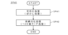
次に、ステップSP40のスクリーン線数変換処理について図7を参照しながら説明する。たとえば、網点線数が150線である網点画像領域SRを別の網点線数(ここでは106線)の網点画像へと再変換することができる。
【0067】
そのため、まずステップSP41において、平均化処理(ぼかし処理)を行う。具体的には、6画素×6画素のサイズの単純平均化処理を行うぼかしフィルタ(平均化フィルタ)などを用いることができる。
【0068】
次のステップSP42においては、網点画像領域SRとは異なる線数のスクリーンパターンを用いて、再び網点化処理(再RIP)を行う。これにより、再RIP画像QA(図2参照)を得ることができる。なお、ステップSP41,SP42の処理は、ぼかし等処理部61により行われる。
【0069】
さらに、ステップSP43において、合成処理を行う。具体的には、上記のステップSP30の処理結果画像をマスク画像QM(図2参照)として用いる。すなわち、マスク画像QMにおいて画素値が「0」の画素については、ステップSP41,SP42で生成された再RIP画像QAの対応画素を出力し、マスク画像QMにおいて画素値が「1」の画素については、元の画像QB(図2参照)の対応画素をそのまま出力する。
【0070】
すなわち、網点画像領域内の画素であると判定された画素についてはステップSP41,SP42の処理を施した結果を採用し、文字領域内の画素であると判定された画素についてはステップSP41,SP42の処理を施さない結果を採用することによって、指定領域DRにおける文字領域と網点画像領域とを分離した上で、画像の劣化を抑制しつつスクリーン線数変換処理を行うことができる。
【0071】
なお、ここでは、指定領域DR内の全ての画素について、ステップSP41,SP42の処理を行う場合について説明したが、マスク画像QMの画素値が「0」の画素のみについてステップSP41,SP42の処理を行った上で、合成するようにしても良い。マスク画像QMにおいて画素値が「1」の画素については、ステップSP41,SP42の処理を行わないので、効率的に処理することができる。すなわち、処理の高速化が可能である。
【0072】
図26は、図28の処理対象画像について生成されたマスク画像QMの一例を表す図である。図26においては、黒色領域が画素値「1」を表しており、文字に該当する領域およびその近傍領域に黒色領域が存在している様子が示されている。言い換えれば、文字領域CRが網点画像領域SRから的確に分離されていることが判る。
【0073】
また、図27は、図26のマスク画像QMを用いて、ステップSP40のスクリーン線数変換処理を行った結果を示す図であり、図30に対応する一部拡大図である。このように、従来技術に見られた文字のぼけを解消して、文字を鮮明に出力することが可能である。
【0074】
<C.変形例等>
<網点情報の自動抽出>
上記においては、網点画像領域SRの網点情報を操作者の入力によって得る場合について説明した。しかしながら、上述したように、網点画像領域SRに基づいてこの網点画像領域SRの網点情報を自動的に抽出することも可能である。以下では、この自動抽出動作について説明する。なお、この自動抽出動作は、網点情報抽出部30によって行われる。
【0075】
また、領域指定部12を用いて指定された領域が複数存在する場合には、それらの複数の指定領域のそれぞれについて、網点情報を取得することが好ましい。これにより、各指定領域に含まれる網点画像領域SRの網点情報が互いに異なっている場合にも、各網点画像領域SRの網点情報を的確に抽出することができる。
【0076】
図17は、網点情報抽出処理の概要を表すフローチャートであり、図18は、網点情報の抽出処理に関する説明図である。
【0077】
図17に示すように、中間値領域抽出処理(ステップSP21)、自己相関データ算出処理(ステップSP22)、網点情報決定処理(ステップSP23)の各処理が行われる。
【0078】
まず、図17のステップSP21において、中間値領域抽出処理が行われる。
【0079】
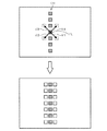
具体的には、この処理は、指定領域DR(もしくは処理対象画像全体)に対する縮小平均処理を用いて行う。たとえば、図18(a)に示すように、元の画像の指定領域DR内の64画素×64画素の画素値を加算して平均化することによって、変換後画像(言い換えれば縮小画像)DSの1画素の画素値を一旦算出する。そして、図18(b)に示すように、この縮小画像DSにおける画素のうちその画素値が中間的な値(たとえば最大階調値の10%〜90%の階調値)となる画素ESを選択し、その縮小画像DSにおける各選択画素ESに対応する各領域ERを元画像の指定領域DRから抽出する処理を行う。
【0080】
ここにおいて、この指定領域DR内の黒塗りのベタ領域や空白部分の変換後の画素値は非常に大きな値もしくは非常に小さな値になる一方で、指定領域DR内の文字領域部分や網点画像領域部分に対応する変換後の画素ESの画素値は、中間的な値(中間値)となる。したがって、元画像の網点画像領域SRの部分は、縮小画像において中間値を有する画素として表現される。ここでは、この性質を利用して、縮小画像DSにおいて中間値を有する複数の画素のうち幾つかの画素ESを抽出し、その各抽出画素ESに対応する元の画像の各領域を中間値領域ERとして抽出するのである。すなわち、これらの中間値領域ERは、網点画像領域SRの候補として抽出される。
【0081】
つぎに、ステップSP22において、これらの各中間値領域ERに対して、以下に説明する自己相関データの算出処理を行う。
【0082】
図19は、各中間値領域ER内の注目画素(xc,yc)の自己相関データを求める手法について説明する図である。注目画素としては、たとえば中間値領域ERの中央に位置する画素を採用することができる。
【0083】
この注目画素(xc,yc)についての周期性データは、処理対象画像における周期的な画像パターンの繰り返しを調べることにより算出される。
【0084】
具体的には、まず、以下の数1によって注目画素(xc,yc)の周辺領域の自己相関データS(a,b)を求める。
【0085】
【数1】

但し、ABS{}は絶対値を求める関数、P(x,y)は処理前画像の画素(x,y)の階調値、m,nは差分積算領域Eを決める定数、a,bは自己相関を比較するズラシ量、wx,wyは1つの中心画素(xc,yc)に対して自己相関特性を調べる範囲Wを決める定数である。
【0087】
(xc,yc)=(4,4)、m=n=1(差分積算領域:3×3)、wx=xy=2(a=b=-2〜+2)とした場合において、a=b=+2のときの自己相関データS(a,b)の算出形態を図19に示す。
【0088】
なお、m,n,wx,wyは予め設定された固定値として処理するようにしてもよいし、入力部6からオペレータによって適宜に変更可能に構成してもよい。
【0089】
ところで、上記の数1では、自己相関データを2次元的に求めているが、以下では簡単化のため、1次元的な自己相関データを用いてその抽出原理を説明する。
【0090】
具体的には、2次元の処理前画像内で互いに直交する2つの画素列方向であるx方向、y方向それぞれに沿った周期的な画像パターンの繰り返しの存在を調べて周期画像領域を抽出する場合を想定して説明する。具体的には、x方向、y方向それぞれに沿った1次元的な自己相関データH(a)、V(b)を以下の数2、数3によって求める。
【0091】
【数2】
【数3】
(xc,yc)=(4,4)、m=1(差分積算領域:3×1)、wx=2(a=-2〜+2)とした場合において、a=+2のときのx方向に沿った自己相関データH(a)の算出形態を図20に、また、(xc,yc)=(4,4)、n=1(差分積算領域:1×3)、wy=2(b=-2〜+2)とした場合において、b=+2のときのy方向に沿った自己相関データV(b)の算出形態を図21にそれぞれ示す。
【0094】
つぎに、ステップSP23において、上記で求めた自己相関データ(S(a,b)、または、H(a)、V(b))に基づき、画像中における周期的な画像パターンの繰り返しの有無を調べることにより、網点情報を決定する処理を行う。
【0095】
網点画像において同程度の中間階調値を有する部分のように、周期的な画像パターンの繰り返しが存在する部分では、その画像パターンの周期ごとに自己相関が高くなり、上記数1、数2、数3で求まる自己相関データは規則的に小さくなる。従って、まず、(A)自己相関データの極小値を検索し、(B)それら極小値が所定レベル以下で、かつ、(C)それら極小値が規則的に存在していることを調べる。なお、(C)の処理は、注目画素に対する対称性を考慮する処理であるともいえる。
【0096】
以下では、自己相関データH(a)を用いてその抽出原理を説明する。
【0097】
図22は(xc,yc)=(7,3)、m=1、wx=5(a=-5〜+5)とした場合のP(x,y)、H(a)の一例を示すデータとそのH(a)をグラフ化した図である。すなわち、同図は注目画素(xc,yc)=(7,3)について、当該注目画素を含む注目領域と当該注目領域以外の周辺領域との相関特性を示すものである。なお、a=0は、同じ画素どうしの自己相関であるので、H(0)=0となり極小値になる。
【0098】
自己相関データH(a)について、上記(A)の処理は、〔(H(k-1)>H(k))and(H(k)<H(k+1))〕の条件を満たすkを+側と−側とで求める。この条件を満たすkについてのH(k)の値が極小値となる。
【0099】
上記(B)の処理は、上記(A)の条件を満たすH(k)、すなわち極小値となるH(k)が所定のしきい値以下となるか否かで判定する。このしきい値は、予め入力部6等によって複数が設定されており、例えば図22においては、”SL1=7.5”が設定されている。そして、極小値となるH(k)がしきい値SL1以下となっていれば、上記(B)の処理において、所定レベル以下であると判定される。
【0100】
上記(C)の処理では、例えば、上記(A)の条件を満たす+側のkをkp、−側のkをkmとしたとき(ABS{kp+km}≦1)を満たすか否かで規則性の有無を判定する。H(a)に極小値が存在しても、ある程度大きかったり(しきい値SL1を越えていたり)、それら極小値が不規則に存在しているような場合は周期性が有るとは言い難い。この処理においては、上記(B)によりレベル判定が行えるので、周期性の有無をより確実に判定できる。また、上記(C)を用いて極小値の規則性を判別することにより、周期性の有無をさらに確実に判定できる。
【0101】
従って、上記(A)、(B)、(C)の条件を全て満たす場合、注目画素(xc,yc)の周囲の範囲W内の画像に周期的な画像パターンの繰り返しが存在することになる。これに対して、図23に示すような自己相関データH(a)には周期性が無く、周期的な画像パターンの繰り返しが存在しないこととなる。なお、文字領域CRにおいては、通常、図23の状態になる。
【0102】
上記では1次元的な処理について説明したが、上記と同様の処理を2次元的に行うことが好ましい。具体的には、1次元的な自己相関データH(a)の代わりに2次元的な自己相関データS(a,b)を用いて同様の処理を行うことにより、距離dX,dYを得ることができる。
【0103】
具体的には、図24に示すように、上記条件(A),(B),(C)を満たす極小値を有する画素のうち、注目画素からの距離が最も小さな画素EMを求める。そして、その画素EMの位置に応じた距離dX,dYを求めればよい。この各距離dX,dYは、周期値算出部33によって求められる。また、周期方向算出部32は、画像パターンの繰り返しの方向である周期方向θを(arctan(dY/dX))として算出することも可能である。なお、精度をそれほど必要としない場合などには、条件(C)を満足しないものをも画素EMとして採用しても良い。
【0104】
以上のようにして、指定された複数の注目画素(xc,yc)のそれぞれについて、距離dX,dYが周期性データとして算出される。なお、上記の画素EMは、注目画素に対して4つの方向に存在し得るが、このステップSP23においては、このうち1つの方向の画素EMに関する距離dX,dYを求めるだけでも良い。具体的には、各注目画素について、第1象限から第4象限の4つの象限のうちの所定の1つの象限に存在する画素の中から、画素EMを選択するようにすればよい。
【0105】
さらに、このようにして得られた複数の注目画素についての距離dX,dYを用いて、各距離dX,dYの平均値を求める。そして、この平均値が、網点画像領域SRに関する距離dX,dYに関する算出結果として得られる。
【0106】
ここで、(距離dX,距離dY)の組合せは、(網点線数,網点角度)の組合せとして表現されることも可能であり、これらの表現は互いに等価である。すなわち、距離dX,距離dYを求めることは、網点情報を求めことと等価である。以上のようにして、網点情報決定処理が行われる。
【0107】
なお、4方向ベクトル算出部40は、この距離dX,距離dYの情報を用いることによって、4方向ベクトルV1〜V4を求めることができる。具体的には、たとえば、距離dX,dYに基づいて1つのベクトル(たとえばV1)を求めるとともに、そのベクトル(V1)に対して90度ずつずらしたベクトルを他の3つのベクトル(V2〜V4)として求めることができる。また、その他の動作は、上記実施形態と同様に行えばよい。
【0108】
<その他>
上記の階調値(ないしは画素値)の大小と画像の明暗(黒白)との関係は、階調値が大きいほど画像が白くなる(言い換えれば階調値が小さいほど画像が黒くなる)ものとして規定される場合と、階調値が大きいほど画像が黒くなる(言い換えれば階調値が小さいほど画像が白くなる)ものとして規定される場合とが存在する。本発明はいずれの場合にも適用することが可能である。
【0109】
また、上記実施形態においては、画像中に複数の種類の網点情報を有する網点画像領域SRが混在する場合に、網点情報を各指定領域DRごとに別個に求める技術について例示した。しかしながら、本発明はこれに限定されず、網点情報を所定のブロック単位で抽出することによっても、網点情報を的確に求めることが可能である。
【0110】
たとえば、図25に示すように、所定の区分領域であるブロックBi(図25参照)ごとに網点情報を抽出することができる。図25は、処理対象画像であるデジタル画像を複数のブロック(区分領域)Bi(i=1,...,N;ただしNは区分数であり、ここではN=24)に区分した状態を表す図である。この図25においては、各ブロックBiは破線で区分された各領域として示されている。
【0111】
ここでは、1つのブロックBi内に最大1個の網点画像領域SRが存在するように、処理対象画像が区分されているものとする。このように区分されたブロックBiごとに網点情報を抽出することにより、画像中に複数の種類の網点情報を有する網点画像領域SRが混在する場合であっても、各網点画像領域SRごとに異なる網点情報を的確に求めることができる。
【0112】
さらに、上記実施形態においては、コンピュータにおいてソフト的に上記各機能を実現することにより画像処理装置1を構成したが、これに限定されず、ロジック回路などのハードウエアを用いて同様の処理を実現する画像処理装置を構築するようにしても良い。
【0113】
【発明の効果】
以上のように、請求項1ないし請求項11に記載の発明によれば、網点情報に基づいて所定の網点と4つの隣接網点のそれぞれとを結ぶ4つのベクトルを求め、注目画素からその4つのベクトルのそれぞれに相当するベクトル量だけ移動させた4つの近傍画素を選択し、その4つの近傍画素と注目画素とを用いて、注目画素が網点画像領域内の画素であるか文字領域内の画素であるかについての判定することができるので、デジタル画像内における網点画像領域と文字領域とを分離することが可能である。
そして、網点画像領域内の画素であると判定された画素についてはぼかし処理および再網点化処理を施した結果を採用し、文字領域内の画素であると判定された画素についてはぼかし処理および再網点化処理を施さない結果を採用するので、網点画像領域と文字領域とを分離してスクリーン線数変換処理を行うことが可能である。
【0114】
特に、請求項2に記載の発明によれば、デジタル画像に対する平滑化処理を行う手段をさらに備え、判定手段は、平滑化処理が施された画像に対して判定処理を行うので、ノイズを抑制することができる。
【0115】
また、請求項3に記載の発明によれば、判定手段は、注目画素およびその周辺画素を含む領域に対するメディアンフィルタ処理を用いて、当該判定処理における判定結果を修正するので、ノイズを抑制することができる。
【0116】
さらに、請求項4に記載の発明によれば、判定手段は、文字領域として判定される領域を拡張する太らせ処理を用いて判定結果を修正するので、文字領域と網点画像領域との境界領域において文字領域としての判定を優先することができる。したがって、たとえばスクリーン線数変更処理をさらに行う場合においては、文字を鮮明に維持した上で網点画像領域の線数を変換することが可能になる。
【0117】
また、請求項6に記載の発明によれば、網点情報抽出手段によって抽出された情報を網点情報として自動的に取得するので、操作性が高い。
【0118】
さらに、請求項7に記載の発明によれば、判定処理を行うべき領域を指定するので、処理対象領域を限定することによる高速化を図ることができる。
【0119】
さらに、請求項8に記載の発明によれば、網点情報取得手段は、領域指定手段により指定された領域ごとに網点情報を取得するので、的確に網点情報を取得することができる。
【0120】
また、請求項9に記載の発明によれば、網点情報抽出手段は、網点情報を所定のブロック単位で抽出するので、的確に網点情報を取得することができる。
【図面の簡単な説明】
【図1】本発明の実施形態に係る画像処理装置1のハードウエア構成を表す図である。
【図2】画像処理装置1の機能ブロック図である。
【図3】画像処理装置1におけるスクリーン線数変換処理の動作を示すフローチャートである。
【図4】網点画像領域SR等を表す図である。
【図5】4方向ベクトルの算出原理を説明する図である。
【図6】ステップSP30の詳細動作を表すフローチャートである。
【図7】ステップSP40の詳細動作を示すフローチャートである。
【図8】元の画像の網点画像領域SRおよび文字領域CRを示す図である。
【図9】元の画像の各領域SR,CRの画素値を表す図である。
【図10】加算結果RVを示す図である。
【図11】二値化処理の結果を示す図である。
【図12】メディアンフィルタ処理結果の他の一例を示す図である。
【図13】太らせ処理の結果を示す図である。
【図14】平滑化フィルタの一例を示す図である。
【図15】網点画像領域SRに対する処理結果を示す概念図である。
【図16】文字領域CRに対する処理結果を示す概念図である。
【図17】網点情報抽出処理の概要を表すフローチャートである。
【図18】網点情報抽出処理の説明図である。
【図19】中間値領域内の注目画素(xc,yc)の自己相関データを求める手法について説明する図である。
【図20】x方向に沿った自己相関データH(a)の算出形態を示す図である。
【図21】y方向に沿った自己相関データV(b)の算出形態を示す図である。
【図22】P(x,y)、H(a)の一例を示すデータとそのH(a)をグラフ化した図である。
【図23】周期的な画像パターンの繰り返しが存在しない自己相関データH(a)の一例を示す図である。
【図24】周期方向θを示す図である。
【図25】複数のブロックBiを示す図である。
【図26】図28の処理対象画像について生成されたマスク画像QMの一例を表す図である。
【図27】本発明を用いたスクリーン線数変換処理結果の一例を示す図である。
【図28】処理対象画像の一例を示す図である。
【図29】図28の左上側の文字部分を拡大して示す図である。
【図30】この処理対象画像に対して従来技術に係るスクリーン線数変換処理を施した画像を示す図である。
【符号の説明】
1 画像処理装置
50 文字網点分離処理部
60 スクリーン線数変換処理部
Bi ブロック
CR 文字領域
D0 網点
D1〜D4 各隣接網点
DR 指定領域
E1〜E4 近傍画素
PE 注目画素
QM マスク画像
SR 網点画像領域
V1〜V4 ベクトル
Θ 網点角度[0001]
BACKGROUND OF THE INVENTION
The present invention relates to an image processing technique for processing a digital image, and more particularly to an image processing technique for processing a digital image having a halftone dot image area and a character area.
[0002]
[Related technologies]
There are cases where an image input using an image reading device such as a scanner is further output.
[0003]
In such a case, when the resolution of the input digital image is relatively large and the resolution of the output device is relatively small (for example, a halftone image having a line number of 133 lines or more is reduced to a smaller line number ( For example, in the case of outputting as an image having (106 lines), gradation collapse or tone jump may occur.
[0004]
In order to avoid such a situation, it is conceivable to perform a process of converting the number of halftone dots (hereinafter also referred to as “screen line number conversion process”) after the blurring process is performed on the input image. If only the process of converting the number of halftone dots is performed without performing the blurring process, the screen pattern having the old and new halftone line numbers causes a periodic interference state, and moire occurs. Therefore, in order to avoid this, it is necessary to perform a blurring process in the screen line number changing process.
[0005]
[Problems to be solved by the invention]
However, if the screen line number conversion process including the blurring process described above is performed on a digital image having both a halftone dot image area and a character area, characters in the character area are blurred. FIG. 28 is a diagram showing an example of a processing target image having a halftone dot image region SR and a character region CR, and FIG. 29 is an enlarged view of the upper left character portion of FIG. FIG. 30 is an image obtained by performing the above-described screen line number conversion processing on the processing target image. FIG. 30 shows a situation where characters are blurred as a result of the screen line number conversion process.
[0006]
This phenomenon is caused by performing the same processing on both areas (halftone image area and character area) having different properties. That is, it is required to separate the halftone dot image area and the character area in the digital image.
[0007]
Further, separating the halftone dot image area and the character area as described above is required not only when performing screen line number conversion processing, but also when performing various processes in digital image processing having both areas. Technology.
[0008]
In view of the above problems, an object of the present invention is to provide a technique capable of separating a halftone dot image area and a character area in a digital image.
[0009]
[Means for Solving the Problems]
In order to achieve the above object, an image processing apparatus according to
[0011]
Claim2The image processing apparatus described in claim1The image processing apparatus described above further includes means for performing a smoothing process on the digital image, and the determination unit performs the determination process on the image that has been subjected to the smoothing process.
[0012]
Claim3The image processing apparatus according to claim 1.OrClaim2In the image processing apparatus according to the
[0013]
Claim4The image processing apparatus according to
[0014]
Claim5The image processing apparatus according to
[0015]
Claim66. The image processing apparatus according to
[0016]
Claim7The image processing apparatus according to
[0017]
Claim8The image processing apparatus described in claim7In the image processing apparatus described in the
[0018]
Claim9The image processing apparatus according to
[0020]
Claim10The recording medium described inBy using the CPU and memory of the computer,A computer according to
[0021]
Claim11The program described inBy using the CPU and memory of the computer,A computer according to
[0022]
DETAILED DESCRIPTION OF THE INVENTION
Hereinafter, embodiments of the present invention will be described with reference to the drawings.
[0023]
<A. Configuration>
FIG. 1 is a conceptual diagram illustrating a hardware configuration of an
[0024]
This computer reads various software programs (hereinafter also referred to simply as “programs”) recorded on the
[0025]
As described above, the
[0026]
FIG. 2 is a functional block diagram of the
[0027]
The
[0028]
The
[0029]
<B. Operation>
<Overview of operation>
FIG. 3 is a flowchart showing the operation of the screen line number conversion process in the
[0030]
First, in step SP10, the
[0031]
Further, the operator (operator) of the
[0032]
Specifically, as shown in FIG. 4, in the digital image P displayed on the screen, an area DR including a halftone image area SR can be designated as a process target area. The designated area DR may include not only the halftone dot image area SR but also the character area CR, and may include a plurality of halftone dot image areas SR having the same halftone dot information. Even in such a case, the subsequent processing can be performed satisfactorily. However, when the plurality of halftone dot image areas SR have different halftone dot information, it is preferable to designate each halftone dot image area SR as a separate area.
[0033]
This designation process is performed using the
[0034]
Next, in step SP20, halftone dot information about the halftone dot image region SR included in the processing target region is acquired. This halftone dot information is information including “the number of halftone lines” and “halftone angle” for the screen pattern used when the halftone image region SR is generated. The number of halftone lines is the number of screen lines per inch of the screen pattern, and the halftone angle is the angle formed by the screen pattern and the image.
[0035]
Here, it is assumed that the operator inputs the halftone dot information. Specifically, using the halftone dot information input unit 20 (FIG. 2), the operator includes halftone dot information (more specifically, the number of halftone lines and the halftone angle) regarding the halftone dot image region SR. Information). As a result, the
[0036]
Also, as shown in FIG. 4, when a plurality of areas are designated as the process target area DR, it is preferable to obtain halftone dot information for each process target area (designated area). Thereby, even when the halftone dot information such as the number of halftone lines is different for each designated area, the halftone dot information can be accurately extracted.
[0037]
Although the halftone dot information of the halftone dot image area SR can be automatically extracted based on the halftone dot image area SR by using the halftone dot
[0038]
Further, in step SP20, processing for obtaining four different vectors connecting a predetermined halftone dot and an adjacent halftone dot is further performed based on the halftone dot information. This process is performed by the four-direction
[0039]
FIG. 5 is a diagram for explaining the principle. For example, as shown in FIG. 5, when the halftone dot angle Θ of the halftone image region SR is 45 degrees, the halftone dots D1 to D4 adjacent to the predetermined halftone dot D0 are separated from the predetermined halftone dot D0. It is located in four directions, lower right, lower left, upper left, and upper right. Further, when the number of halftone lines (number of lines per inch) of this halftone image region SR is 150 lines, and the resolution (number of pixels per inch) of the processing target image is 600 (dpi). The distance corresponding to 600/150 = 4 pixels corresponds to the distance D from the halftone dot D0 to the adjacent halftone dot. Accordingly, in this case, the horizontal distance dX from the halftone dot D0 to the adjacent halftone dot D1 is a value obtained by multiplying the value D (= 4) by cos Θ (cos 45 degrees) (that is, about 2.8), and is vertical. The directional distance dY is a value obtained by multiplying the value D (= 4) by sin Θ (sin 45 degrees) (that is, about 2.8). Accordingly, a vector V1 = (dX, dY) having the halftone dot D0 as the start point and the adjacent halftone dot D1 as the end point is obtained.
[0040]
Then, similar distances dX and dY are obtained for all of the other adjacent halftone dots D2 to D4 in the three directions. That is, a vector V2 having a halftone dot D0 as a start point and an adjacent halftone dot D2 as an end point is obtained, and a vector V3 having a halftone dot D0 as a start point and an adjacent halftone dot D3 as an end point, and a halftone dot D0 as a start point and A vector V4 whose end point is the adjacent halftone dot D4 is obtained. In this way, four different vectors V1 to V4 connecting the predetermined halftone dot D0 and each of the adjacent halftone dots D1 to D4 are obtained. These four vectors V1 to V4 are used in step SP30 described later.
[0041]
Further, in step SP30 (FIG. 3), a process for generating a mask image for separating the character region CR (FIG. 4) and the halftone dot image region SR for the designated region DR is performed, and then in step SP40, A screen line number conversion process is performed using the mask image. Hereinafter, the operations in step SP30 and step SP40 will be described in detail with reference to FIGS. FIG. 6 is a flowchart showing the detailed operation of step SP30, and FIG. 7 is a flowchart showing the detailed operation of step SP40.
[0042]
<Mask image generation operation>
Next, the mask image generation operation (step SP30) will be described.
[0043]
8 to 13 are diagrams for explaining this operation. FIG. 8 is an enlarged view in which a partial region of the processing target image is extracted. FIG. 8A shows a partial region in the halftone dot image region SR, and FIG. 8B shows the character region CR. The partial area | region is shown. Each square unit region in FIG. 8 represents one pixel, and pixels indicated by diagonal lines represent black pixels in the processing target image. FIG. 9 is a diagram showing the pixel values of each region. FIG. 9 (a) corresponds to FIG. 8 (a), and FIG. 9 (b) corresponds to FIG. 8 (b). is doing. Further, FIGS. 10 to 13 are diagrams showing the pixel values of the respective regions according to the progress of the following steps, and FIG. 10 (a) shows the processing results for FIG. 9 (a). (B), FIG. 11, and FIG. 13 show the processing results for FIG. 9 (b).
[0044]
Below, the process of each step is demonstrated, referring FIG.
[0045]
First, as shown in FIG. 6, in step SP31, the smoothing processing unit 51 performs smoothing processing on the digital image. This smoothing process can be realized by using, for example, a smoothing filter as shown in FIG. This smoothing filter is a filter having a size of 3 × 3 pixels. The weighting coefficient of the center is 4 and the weighting coefficients of the surrounding 8 pixels are 1 and 2, respectively. By using this smoothing filter, it is possible to calculate a weighted average value in which the pixel value of the target pixel (center pixel) is considered in consideration of the pixel values of surrounding pixels.
[0046]
Here, the process (smoothing process) of step SP31 is not necessarily performed, but the smoothing process of step SP31 is performed before each of the following steps SP33 to SP38 in order to suppress noise at the time of determination. It is preferable to carry out. In other words, it is preferable to perform determination processing such as the following steps SP33 to SP37 on the image that has been subjected to the smoothing processing.
[0047]
In addition, when the processing target image is a binary image, by performing this smoothing process, it is possible to simultaneously perform a process for converting the pixel value of each pixel into a multivalued image. For example, when this binary image is converted into a multi-value image having 256 levels of gradation values, as described above, the gradation values 0 and 1 of each pixel of the binary image are set for convenience. This smoothing process is performed after conversion into 0,255 in advance. Each pixel of the image after the smoothing process also has a gradation value other than 0, 255, and is subjected to a weighted average process that takes into account the pixel values of surrounding pixels and is then multivalued. The
[0048]
Next, in steps SP33 to SP37 (FIG. 6), a determination process is performed as to whether the target pixel is a pixel in the halftone image area or a pixel in the character area. This determination process is roughly divided into the following five processes: (1) a process of selecting four neighboring pixels moved by a vector amount corresponding to each of the four vectors from the target pixel (step SP33); 2) a process for obtaining the absolute value of the difference between the target pixel and each of the four neighboring pixels (step SP34), and (3) a process for obtaining an addition result obtained by adding these four difference absolute values (step SP35). (4) A determination process based on the magnitude relationship between the addition result and a predetermined threshold (step SP36), and (5) a process of applying a median filter to the determination result (step SP37). Hereinafter, each process will be described.
[0049]
First, in step SP33, (1) a process of selecting four neighboring pixels moved from the target pixel by a vector amount corresponding to each of the four vectors is performed. FIG. 8A shows four neighboring pixels E1 to E4 that exist at positions shifted by vectors V1 to V4 with respect to the target pixel PE, respectively. Here, what was calculated | required in said step SP20 is used as vectors V1-V4. Therefore, when it is assumed that the target pixel PE exists at the position of the predetermined halftone dot D0, the four pixels existing at the positions of the adjacent halftone dots D1 to D4 are selected as the four neighboring pixels E1 to E4. It will be.
[0050]
Next, in step SP34, (2) a process for obtaining an absolute value of a difference between the target pixel PE and each of the four neighboring pixels E1 to E4 is performed. Specifically, the absolute value A1 of the difference between the pixel value EV of the target pixel PE and the pixel value EV1 of the neighboring pixel E1 is obtained, and the difference between the pixel value EV of the target pixel PE and the pixel value EV2 of the neighboring pixel E2 is obtained. Find the absolute value of. Similarly, the absolute value of the difference between the pixel value EV of the target pixel PE and the pixel value EV3 of the neighboring pixel E3 and the absolute value of the difference between the pixel value EV of the target pixel PE and the pixel value EV4 of the neighboring pixel E4 are obtained.
[0051]
In step SP35, the four difference absolute values obtained in step SP34 are added, and the addition result RV is obtained. Here, a value obtained by dividing the addition result by 4 (that is, an average value) is obtained as a new addition result RV, and the new addition result RV is compared with the threshold value TH. FIG. 10 is a diagram showing the addition result RV. FIG. 10 shows the processing result for FIG. 9 and illustrates the case where step SP31 is not performed for the sake of simplicity. As described above, FIG. 10A shows the processing result for FIG. 9A (that is, the processing result for the halftone image region SR), and FIG. 10B shows the processing result for FIG. 9B. A processing result (that is, a processing result for the character region CR) is shown. The processes in steps SP33 to SP35 are performed by the difference value
[0052]
In the next step SP36, the addition result RV is compared with a predetermined threshold value TH, and binarization processing is performed based on the magnitude relationship. This binarization processing is performed by the
[0053]
The predetermined threshold TH has a different value depending on the type of halftoning method (for example, error diffusion method or simple binarization method) when the halftone image region SR is formed. It may be determined. Specifically, when the type of the halftone method is known, the threshold TH corresponding to the type can be set. For example, the threshold TH for the halftone dot image region SR by the error diffusion method can be set to 80, and the threshold TH for the halftone dot image region SR by the simple binarization method can be set to 100. In this way, by setting the threshold value TH as a value corresponding to the type of the halftone method, this binarization process can be performed more appropriately. In addition, as information regarding the type of halftone dot conversion method, information input by the operator using the halftone dot
[0054]
Here, a value obtained by dividing the addition result by 4 (that is, an average value) is obtained as a new addition result RV, and the new addition result RV is compared with the threshold value TH. The addition result RV may be directly compared with the threshold value TH. The threshold value TH in that case may be determined as having a value four times the threshold value TH when the averaged addition result is used.
[0055]
Thus, the processing target image is binarized based on the magnitude relationship between the addition result RV and the threshold value TH. As a result of the binarization processing, a portion having the value “0” is determined as having a high possibility of being a pixel in the halftone image region, and a portion having the value “1” is determined to be a pixel in the character region. It is determined that there is a high possibility of being.
[0056]
This determination operation is based on the following principle.
[0057]
As shown in the upper part of FIG. 15, in the halftone image region SR, when the halftone dots expressing the same intermediate gradation value are continuous, the target pixel PE and its four neighboring pixels E1 to E4 are mutually connected. Have approximately equal pixel values. Therefore, as shown in the lower part of FIG. 15, the difference absolute value becomes small (ideally the difference absolute value = 0), and the addition result RV becomes a small value. Therefore, the portion having the value “0” is highly likely to be a pixel in the halftone image area. The lower part of FIG. 15 shows a state corresponding to the result of FIG.
[0058]
On the other hand, as shown in FIG. 16, in the character region CR, since the distribution of pixel values is non-uniform, the pixel value of the pixel of interest PE and its four neighboring pixels E1 to E4 often differ greatly. The difference absolute value becomes large and the addition result RV becomes a large value. Therefore, the portion having the value “1” is highly likely to be a pixel in the character area. 16 shows a state corresponding to the result of FIG. 10B. In FIG. 16, a white square area indicates an area having a pixel value between the black area and the white area.
[0059]
In the lower part of FIG. 16 and FIG. 10B, the processing of steps SP33 to SP36 is performed when a thin line having a width of about one pixel to several pixels (two pixels in FIG. 10B) continues in one direction. The applied results are shown. As shown in these figures, the absolute difference value remains as a relatively large value.
[0060]
Based on this principle, a pixel having the value “0” is determined to be a pixel in the halftone image area, and a portion having the value “1” is determined to be a pixel in the character area. Can do.
[0061]
Here, since the absolute difference values with respect to all neighboring pixels in the four directions toward the adjacent halftone dot are taken into account, erroneous determination due to direction dependency can be prevented. In other words, an accurate determination operation can be realized as compared with a case where only two of the four directions are considered.
[0062]
Further, in step SP37, a median filter process is performed on the determination result. This median filter is a filter having a predetermined size (for example, 3 × 3 pixels), and pays attention to the central value of a predetermined number (here, nine) of pixels including the target pixel and its surrounding pixels. It is a filter which makes a pixel value of a pixel. For example, when a median filter having a 3 × 3 pixel size is used, the fifth value among the nine pixels including the target pixel and its surrounding pixels can be set as the pixel value of the target pixel. When this median filter is applied, a pixel having a pixel value equal to or higher than the threshold TH is present alone without having a pixel with a high gradation value in the periphery (in short, it is present as an “enclave”) ), The pixel value of the pixel can be corrected (more specifically, corrected to zero). In this way, by correcting the determination result using the median filter process, it is possible to suppress noise due to the presence of the “outskirt”. When this median filter is applied to the processing result of FIG. 11, the result is the same as FIG.
[0063]
FIG. 12 is a diagram showing another example of the median filter processing in step SP37, FIG. 12A shows the processing results up to step SP36, and FIG. ) Shows the result of median filter processing. Referring to FIG. 12 (b), the “split” that existed in FIG. 12 (a) (in this case, it means a pixel having no more than three pixels of the same pixel value around it). ) Disappears. As described above, by performing the binarization process of step SP36 after the process of step SP37, it is possible to eliminate the enclave as described above. This median filter processing is performed by the median filter processing unit 54.
[0064]
In the next step SP38, a thickening process (specifically, a process of enlarging a portion determined as a character area) is performed on the binary image that is the determination result. For example, a maximum value selection filter having a size of 8 × 8 pixels, 16 × 16 pixels, or the like can be used. This maximum value selection filter is a filter that uses the maximum value of the pixel values in a predetermined area including the target pixel as the pixel value of the target pixel. As a result, the region of the pixel value “1” can be enlarged (in short, thickened). FIG. 13 shows the result of applying the fattening process of step SP38 to the result of FIG. 11 (or FIG. 12B) using a maximum value selection filter having a size of 8 × 8 pixels. . As shown in FIG. 13, the pixel value is “1” not only for the area corresponding to the thin line surrounded by the central thick line but also for the pixels in the peripheral area. That is, the determination result is corrected so that the area determined as the character area CR is enlarged. As described above, when the thickening process in step SP38 is used, the character area CR and the halftone dot image area SR are separated from each other in the boundary area (that is, the boundary area between the character area CR and the halftone dot image area SR). The determination as the region CR is prioritized. Accordingly, in the screen line number changing process described later, it is possible to convert the line number of the halftone dot image region SR while keeping the characters clear. This process is performed by the
[0065]
Through the processing as described above, an image that has been processed up to step SP38 is generated as a mask image. By using this mask image, it is possible to determine whether each pixel of interest is a pixel in the halftone dot image region or a pixel in the character region. That is, it is possible to separate the halftone dot image area and the character area in the digital image.
[0066]
Next, the screen line number conversion process in step SP40 will be described with reference to FIG. For example, a halftone dot image region SR having a halftone dot number of 150 lines can be reconverted into a halftone dot image having a different halftone dot number (here, 106 lines).
[0067]
Therefore, first, in step SP41, an averaging process (blurring process) is performed. Specifically, a blurring filter (averaging filter) that performs a simple averaging process with a size of 6 pixels × 6 pixels can be used.
[0068]
In the next step SP42, halftone processing (re-RIP) is performed again using a screen pattern having a different number of lines from the halftone image region SR. Thereby, the re-RIP image QA (see FIG. 2) can be obtained. The processing in steps SP41 and SP42 is performed by the blurring
[0069]
Further, in step SP43, a synthesis process is performed. Specifically, the processing result image in step SP30 is used as the mask image QM (see FIG. 2). That is, for the pixel having a pixel value “0” in the mask image QM, the corresponding pixel of the re-RIP image QA generated in steps SP41 and SP42 is output, and for the pixel having a pixel value “1” in the mask image QM. The corresponding pixel of the original image QB (see FIG. 2) is output as it is.
[0070]
That is, the result of performing the processing of steps SP41 and SP42 is adopted for the pixel determined to be a pixel in the halftone image area, and the steps SP41 and SP42 are determined for the pixel determined to be a pixel in the character area. By adopting the result of not performing the above process, it is possible to separate the character area and the halftone image area in the designated area DR and perform the screen line number conversion process while suppressing image deterioration.
[0071]
Here, the case where the processing of steps SP41 and SP42 is performed for all the pixels in the designated region DR has been described, but the processing of steps SP41 and SP42 is performed only for the pixels whose pixel value of the mask image QM is “0”. You may make it synthesize | combine after performing. Since the process of steps SP41 and SP42 is not performed for the pixel having a pixel value “1” in the mask image QM, it can be processed efficiently. That is, the processing speed can be increased.
[0072]
FIG. 26 is a diagram illustrating an example of the mask image QM generated for the processing target image in FIG. In FIG. 26, the black area represents the pixel value “1”, and a state where the black area exists in the area corresponding to the character and its neighboring area is shown. In other words, it can be seen that the character region CR is accurately separated from the halftone image region SR.
[0073]
FIG. 27 is a diagram showing a result of the screen line number conversion processing in step SP40 using the mask image QM of FIG. 26, and is a partially enlarged view corresponding to FIG. In this way, it is possible to eliminate the blur of characters found in the prior art and output the characters clearly.
[0074]
<C. Modified example>
<Automatic extraction of halftone dot information>
In the above description, a case has been described in which halftone dot information of the halftone dot image region SR is obtained by an operator input. However, as described above, it is also possible to automatically extract halftone dot information of the halftone dot image region SR based on the halftone dot image region SR. Hereinafter, the automatic extraction operation will be described. This automatic extraction operation is performed by the halftone dot
[0075]
In addition, when there are a plurality of areas designated using the
[0076]
FIG. 17 is a flowchart showing an outline of halftone dot information extraction processing, and FIG. 18 is an explanatory diagram regarding halftone dot information extraction processing.
[0077]
As shown in FIG. 17, the intermediate value region extraction processing (step SP21), autocorrelation data calculation processing (step SP22), and halftone information determination processing (step SP23) are performed.
[0078]
First, in step SP21 of FIG. 17, intermediate value region extraction processing is performed.
[0079]
Specifically, this process is performed using a reduction average process for the designated region DR (or the entire processing target image). For example, as shown in FIG. 18A, by adding and averaging the pixel values of 64 pixels × 64 pixels in the designated area DR of the original image, the converted image (in other words, the reduced image) DS A pixel value of one pixel is once calculated. Then, as shown in FIG. 18B, a pixel ES whose pixel value is an intermediate value (for example, a gradation value of 10% to 90% of the maximum gradation value) among the pixels in the reduced image DS. A process of selecting and extracting each region ER corresponding to each selected pixel ES in the reduced image DS from the designated region DR of the original image is performed.
[0080]
Here, the pixel values after conversion of the black solid area and the blank part in the designated area DR become very large or very small values, while the character area and halftone image in the designated area DR. The pixel value of the converted pixel ES corresponding to the region portion is an intermediate value (intermediate value). Therefore, the halftone dot image region SR of the original image is expressed as a pixel having an intermediate value in the reduced image. Here, using this property, some pixels ES are extracted from the plurality of pixels having the intermediate value in the reduced image DS, and each area of the original image corresponding to each extracted pixel ES is determined as the intermediate value area. It is extracted as ER. That is, these intermediate value areas ER are extracted as candidates for the halftone image area SR.
[0081]
Next, in step SP22, an autocorrelation data calculation process described below is performed for each of the intermediate value regions ER.
[0082]
FIG. 19 is a diagram for explaining a method for obtaining autocorrelation data of a pixel of interest (xc, yc) in each intermediate value region ER. As the pixel of interest, for example, a pixel located at the center of the intermediate value region ER can be employed.
[0083]
The periodicity data for the target pixel (xc, yc) is calculated by examining the repetition of the periodic image pattern in the processing target image.
[0084]
Specifically, first, the autocorrelation data S (a, b) of the peripheral region of the target pixel (xc, yc) is obtained by the following equation (1).
[0085]
[Expression 1]
Where ABS {} is a function for obtaining an absolute value, P (x, y) is a gradation value of the pixel (x, y) of the pre-processing image, m and n are constants for determining the difference integration region E, and a and b are The shift amount wx, wy for comparing the autocorrelation is a constant that determines the range W in which the autocorrelation characteristics are examined for one central pixel (xc, yc).
[0087]
When (xc, yc) = (4,4), m = n = 1 (difference integration region: 3 × 3), wx = xy = 2 (a = b = −2 to +2), a = FIG. 19 shows how the autocorrelation data S (a, b) is calculated when b = + 2.
[0088]
Note that m, n, wx, and wy may be processed as fixed values set in advance, or may be configured to be appropriately changed by the operator from the
[0089]
By the way, in the
[0090]
Specifically, a periodic image region is extracted by examining the presence of repetition of a periodic image pattern along each of the x direction and the y direction, which are two pixel column directions orthogonal to each other in the two-dimensional pre-processing image. A case will be described. Specifically, one-dimensional autocorrelation data H (a) and V (b) along each of the x direction and the y direction are obtained by the following
[0091]
[Expression 2]
[Equation 3]
x when a = + 2 when (xc, yc) = (4,4), m = 1 (difference integration region: 3 × 1), and wx = 2 (a = −2 to +2) The calculation form of the autocorrelation data H (a) along the direction is shown in FIG. 20, and (xc, yc) = (4, 4), n = 1 (difference integration region: 1 × 3), wy = 2 ( FIG. 21 shows calculation forms of autocorrelation data V (b) along the y direction when b = + 2 when b = -2 to +2).
[0094]
Next, in step SP23, based on the autocorrelation data (S (a, b) or H (a), V (b)) obtained as described above, whether or not a periodic image pattern is repeated in the image is determined. By checking, halftone dot information is determined.
[0095]
In a halftone image, such as a portion having a similar halftone value, in a portion where the repetition of a periodic image pattern exists, the autocorrelation becomes higher for each cycle of the image pattern. , The autocorrelation data obtained by
[0096]
Hereinafter, the extraction principle will be described using autocorrelation data H (a).
[0097]
FIG. 22 shows an example of P (x, y) and H (a) when (xc, yc) = (7,3), m = 1, wx = 5 (a = −5 to +5). It is the figure which plotted data and its H (a). That is, this figure shows the correlation characteristics between the attention area including the target pixel and the peripheral area other than the attention area for the target pixel (xc, yc) = (7, 3). Since a = 0 is an autocorrelation between the same pixels, H (0) = 0 and becomes a minimum value.
[0098]
For the autocorrelation data H (a), the process (A) satisfies the condition [(H (k-1)> H (k)) and (H (k) <H (k + 1))]. k is determined on the + side and the − side. The value of H (k) for k that satisfies this condition is the minimum value.
[0099]
The process (B) is determined based on whether or not H (k) that satisfies the condition (A), that is, H (k) that is the minimum value is equal to or less than a predetermined threshold value. A plurality of threshold values are set in advance by the
[0100]
In the processing of (C), for example, regularity is satisfied depending on whether or not (ABS {kp + km} ≦ 1) is satisfied when k on the + side satisfying the condition (A) is kp and k on the − side is km. The presence or absence of is determined. Even if there is a minimum value in H (a), it is difficult to say that there is periodicity if it is large to some extent (beyond the threshold SL1) or if these minimum values exist irregularly. . In this process, since the level can be determined by (B), the presence or absence of periodicity can be determined more reliably. Further, by determining the regularity of the minimum value using (C) above, the presence or absence of periodicity can be determined more reliably.
[0101]
Therefore, when all of the above conditions (A), (B), and (C) are satisfied, the image within the range W around the pixel of interest (xc, yc) has periodic image pattern repetition. . On the other hand, the autocorrelation data H (a) as shown in FIG. 23 has no periodicity and there is no periodic image pattern repetition. Note that the character region CR is normally in the state shown in FIG.
[0102]
Although one-dimensional processing has been described above, it is preferable to perform the same processing as described above two-dimensionally. Specifically, the distances dX and dY are obtained by performing the same processing using the two-dimensional autocorrelation data S (a, b) instead of the one-dimensional autocorrelation data H (a). Can do.
[0103]
Specifically, as shown in FIG. 24, the pixel EM having the smallest distance from the target pixel is obtained from the pixels having the minimum values that satisfy the above conditions (A), (B), and (C). Then, the distances dX and dY corresponding to the position of the pixel EM may be obtained. The distances dX and dY are obtained by the period
[0104]
As described above, the distances dX and dY are calculated as the periodicity data for each of the plurality of designated target pixels (xc, yc). The pixel EM may exist in four directions with respect to the pixel of interest. However, in this step SP23, only the distances dX and dY related to the pixel EM in one direction may be obtained. Specifically, for each target pixel, the pixel EM may be selected from the pixels existing in a predetermined one quadrant among the four quadrants from the first quadrant to the fourth quadrant.
[0105]
Further, using the distances dX and dY for the plurality of target pixels obtained in this manner, an average value of the distances dX and dY is obtained. This average value is obtained as a calculation result regarding the distances dX and dY regarding the halftone image region SR.
[0106]
Here, the combination of (distance dX, distance dY) can also be expressed as a combination of (number of halftone lines, halftone angle), and these expressions are equivalent to each other. That is, obtaining the distance dX and the distance dY is equivalent to obtaining halftone dot information. As described above, the halftone dot information determination process is performed.
[0107]
The four-direction
[0108]
<Others>
The relationship between the above-mentioned gradation value (or pixel value) and the brightness of the image (black and white) is that the image becomes whiter as the gradation value is larger (in other words, the image is blacker as the gradation value is smaller). There are cases where it is defined that the image is black as the gradation value is large (in other words, the image is white as the gradation value is small). The present invention can be applied to either case.
[0109]
Moreover, in the said embodiment, when the halftone dot image area | region SR which has several types of halftone dot information was mixed in the image, the technique which calculates | requires halftone dot information separately for every designated area | region DR was illustrated. However, the present invention is not limited to this, and halftone dot information can be obtained accurately by extracting halftone dot information in units of predetermined blocks.
[0110]
For example, as shown in FIG. 25, halftone dot information can be extracted for each block Bi (see FIG. 25) which is a predetermined segmented area. FIG. 25 shows a state in which a digital image, which is a processing target image, is divided into a plurality of blocks (partition areas) Bi (i = 1,..., N; where N is the number of sections, here N = 24). FIG. In FIG. 25, each block Bi is shown as each area divided by a broken line.
[0111]
Here, it is assumed that the processing target image is divided so that a maximum of one halftone dot image region SR exists in one block Bi. By extracting halftone dot information for each block Bi divided in this way, even if a halftone dot image area SR having a plurality of types of halftone dot information is mixed in the image, each halftone dot image area Different halftone dot information can be accurately obtained for each SR.
[0112]
Furthermore, in the above-described embodiment, the
[0113]
【The invention's effect】
As described above,
Then, the result of performing the blurring process and the re-halftone processing for the pixels determined to be the pixels in the halftone image area is adopted, and the blurring process is performed for the pixels determined to be the pixels in the character area. Since the result of not performing the re-halftone processing is adopted, it is possible to separate the halftone image area and the character area and perform the screen line number conversion process.
[0114]
In particular, the claims2According to the above-described invention, the image processing apparatus further includes means for performing a smoothing process on the digital image, and the determination unit performs the determination process on the image that has been subjected to the smoothing process, so that noise can be suppressed.
[0115]
Claims3According to the above-described invention, the determination unit corrects the determination result in the determination process using the median filter process for the region including the target pixel and the surrounding pixels, and thus noise can be suppressed.
[0116]
And claims4According to the invention described in the above, since the determination unit corrects the determination result using a fattening process that expands the region determined as the character region, the determination unit determines the character region in the boundary region between the character region and the halftone image region. This determination can be prioritized. Therefore, for example, when the screen line number changing process is further performed, it is possible to convert the line number of the halftone image area while keeping the characters clear.
[0117]
Claims6Since the information extracted by the halftone dot information extracting means is automatically acquired as halftone dot information, the operability is high.
[0118]
And claims7According to the invention described in (1), since the area to be subjected to the determination process is designated, the speed can be increased by limiting the process target area.
[0119]
And claims8Since the halftone dot information acquiring unit acquires halftone dot information for each region designated by the region designation unit, the halftone dot information can be accurately obtained.
[0120]
Claims9Since the halftone dot information extracting unit extracts halftone dot information in a predetermined block unit, the halftone dot information can be accurately acquired.
[Brief description of the drawings]
FIG. 1 is a diagram illustrating a hardware configuration of an
FIG. 2 is a functional block diagram of the
FIG. 3 is a flowchart showing an operation of a screen line number conversion process in the
FIG. 4 is a diagram illustrating a halftone dot image region SR and the like.
FIG. 5 is a diagram illustrating a calculation principle of a four-direction vector.
FIG. 6 is a flowchart showing the detailed operation of step SP30.
FIG. 7 is a flowchart showing a detailed operation of step SP40.
FIG. 8 is a diagram illustrating a halftone dot image region SR and a character region CR of an original image.
FIG. 9 is a diagram illustrating pixel values of regions SR and CR of an original image.
FIG. 10 is a diagram illustrating an addition result RV.
FIG. 11 is a diagram illustrating a result of binarization processing;
FIG. 12 is a diagram illustrating another example of the median filter processing result.
FIG. 13 is a diagram illustrating a result of a fattening process.
FIG. 14 is a diagram illustrating an example of a smoothing filter.
FIG. 15 is a conceptual diagram illustrating a processing result for a halftone dot image region SR.
FIG. 16 is a conceptual diagram showing a processing result for a character region CR.
FIG. 17 is a flowchart showing an outline of halftone dot information extraction processing.
FIG. 18 is an explanatory diagram of halftone dot information extraction processing.
FIG. 19 is a diagram illustrating a method for obtaining autocorrelation data of a pixel of interest (xc, yc) in an intermediate value region.
FIG. 20 is a diagram showing a calculation form of autocorrelation data H (a) along the x direction.
FIG. 21 is a diagram showing a calculation form of autocorrelation data V (b) along the y direction.
FIG. 22 is a graph of data showing an example of P (x, y) and H (a) and H (a).
FIG. 23 is a diagram illustrating an example of autocorrelation data H (a) in which there is no repetition of a periodic image pattern.
FIG. 24 is a diagram showing a periodic direction θ.
FIG. 25 is a diagram illustrating a plurality of blocks Bi.
FIG. 26 is a diagram illustrating an example of a mask image QM generated for the processing target image in FIG.
FIG. 27 is a diagram showing an example of a screen line number conversion process result using the present invention.
FIG. 28 is a diagram illustrating an example of a processing target image.
FIG. 29 is an enlarged view of the upper left character portion of FIG.
FIG. 30 is a diagram illustrating an image obtained by performing screen line number conversion processing according to a conventional technique on the processing target image;
[Explanation of symbols]
1 Image processing device
50 character halftone dot separation processor
60 Screen line number conversion processor
Bi block
CR character area
D0 halftone dot
D1 to D4 each adjacent halftone dot
DR specified area
E1-E4 neighboring pixels
PE pixel of interest
QM mask image
SR halftone image area
V1-V4 vector
Θ Halftone angle
Claims (11)
デジタル画像を取得するデジタル画像取得手段と、
前記デジタル画像の網点情報として網点線数と網点角度とを取得する網点情報取得手段と、
前記デジタル画像の解像度と前記網点線数と前記網点角度とに基づいて、所定の網点と4つの隣接網点のそれぞれとを結ぶ4つのベクトルを求める手段と、
注目画素から前記4つのベクトルのそれぞれに相当するベクトル量だけ移動させた4つの近傍画素を選択する手段と、
前記注目画素と前記4つの近傍画素のそれぞれとの差分の絶対値を加算した加算結果を求め、前記加算結果の方が所定値より小さい場合に前記注目画素が前記網点画像領域にあると判定し、前記加算結果の方が所定値より大きい場合に前記注目画素が前記文字領域にあると判定することによって前記注目画素が網点画像領域内の画素であるか文字領域内の画素であるかについての判定処理を行う判定手段と、
前記判定処理の結果に基づいて前記網点画像領域の画素と前記文字領域の画素とが異なる階調値を有する2値画像であるマスク画像を生成するマスク画像生成手段と、
前記デジタル画像についてぼかし処理を行うぼかし処理手段と、
前記ぼかし処理によって得られた画像を前記再網点化する再網点処理を行う再網点化処理手段と、
前記マスク画像を用いて前記網点画像領域にあると判定される画素については前記ぼかし処理および前記再網点化処理を施した結果を採用し、前記文字領域にあると判定される画素については前記ぼかし処理および前記再網点化処理を施さない結果を採用することによって合成画像を生成する合成手段と、
を備えることを特徴とする画像処理装置。An image processing apparatus for processing a digital image,
Digital image acquisition means for acquiring a digital image;
Halftone dot information obtaining means for obtaining a halftone dot number and a halftone dot angle as halftone dot information of the digital image ;
Means for obtaining four vectors connecting a predetermined halftone dot and each of four adjacent halftone dots based on the resolution of the digital image, the number of halftone dots, and the halftone dot angle ;
Means for selecting four neighboring pixels moved from the pixel of interest by a vector amount corresponding to each of the four vectors;
An addition result obtained by adding the absolute values of the differences between the pixel of interest and each of the four neighboring pixels is obtained, and when the addition result is smaller than a predetermined value, the pixel of interest is determined to be in the halftone image area. Whether the pixel of interest is a pixel in the halftone image region or a pixel in the character region by determining that the pixel of interest is in the character region when the addition result is larger than a predetermined value . A determination means for performing a determination process on
Mask image generation means for generating a mask image which is a binary image in which the pixels of the halftone dot image region and the pixels of the character region have different gradation values based on the result of the determination process;
Blur processing means for performing blur processing on the digital image;
Re-halftone processing means for performing re-halftone processing for re-dotting the image obtained by the blurring processing;
For pixels that are determined to be in the halftone image area using the mask image, the result of performing the blurring process and the re-halftone processing is adopted, and for pixels that are determined to be in the character area Combining means for generating a combined image by adopting a result of not performing the blurring process and the re-halftone processing;
An image processing apparatus comprising:
前記デジタル画像に対する平滑化処理を行う手段、
をさらに備え、
前記判定手段は、前記平滑化処理が施された画像について前記判定処理を行うことを特徴とする画像処理装置。The image processing apparatus according to claim 1.
Means for smoothing the digital image;
Further comprising
The image processing apparatus , wherein the determination unit performs the determination process on the image that has been subjected to the smoothing process.
前記判定手段は、前記注目画素およびその周辺画素を含む領域に対するメディアンフィルタ処理を用いて、当該判定処理における判定結果を修正することを特徴とする画像処理装置。The image processing apparatus according to claim 1 or 2,
The determination unit corrects a determination result in the determination process by using a median filter process for an area including the target pixel and its surrounding pixels .
前記判定手段は、文字領域として判定される領域を拡張する太らせ処理を用いて、前記判定結果を修正することを特徴とする画像処理装置。The image processing apparatus according to any one of claims 1 to 3,
The image processing apparatus characterized in that the determination means corrects the determination result by using a fattening process for expanding an area determined as a character area .
前記網点情報取得手段は、前記網点情報を入力する網点情報入力手段を有し、当該網点情報入力手段を用いて入力された情報を前記網点情報として取得することを特徴とする画像処理装置。The image processing apparatus according to any one of claims 1 to 4,
The halftone dot information acquisition means has halftone dot information input means for inputting the halftone dot information, and acquires information input using the halftone dot information input means as the halftone dot information. Image processing device.
前記網点情報取得手段は、前記網点情報を前記デジタル画像から抽出する網点情報抽出手段を有し、当該網点情報抽出手段によって抽出された情報を前記網点情報として取得することを特徴とする画像処理装置。The image processing apparatus according to any one of claims 1 to 5,
The halftone dot information acquisition means includes halftone dot information extraction means for extracting the halftone dot information from the digital image , and acquires the information extracted by the halftone dot information extraction means as the halftone dot information. An image processing apparatus.
前記判定処理を行うべき領域を指定する領域指定手段、
をさらに備えることを特徴とする画像処理装置。The image processing apparatus according to any one of claims 1 to 6 ,
Area designating means for designating an area to be subjected to the determination process;
An image processing apparatus further comprising:
前記網点情報取得手段は、前記領域指定手段により指定された領域ごとに前記網点情報を取得することを特徴とする画像処理装置。The image processing apparatus according to claim 7 .
The image processing apparatus, wherein the halftone dot information acquiring unit acquires the halftone dot information for each region specified by the region specifying unit .
前記網点情報抽出手段は、前記網点情報を所定のブロック単位で抽出することを特徴とする画像処理装置。 Claims 1 image processing apparatus according to claim 8,
The halftone dot information extracting unit extracts the halftone dot information in predetermined block units .
Priority Applications (1)
| Application Number | Priority Date | Filing Date | Title |
|---|---|---|---|
| JP2001048687A JP3934353B2 (en) | 2001-02-23 | 2001-02-23 | Image processing apparatus, recording medium, and program |
Applications Claiming Priority (1)
| Application Number | Priority Date | Filing Date | Title |
|---|---|---|---|
| JP2001048687A JP3934353B2 (en) | 2001-02-23 | 2001-02-23 | Image processing apparatus, recording medium, and program |
Publications (3)
| Publication Number | Publication Date |
|---|---|
| JP2002252756A JP2002252756A (en) | 2002-09-06 |
| JP2002252756A5 JP2002252756A5 (en) | 2004-12-02 |
| JP3934353B2 true JP3934353B2 (en) | 2007-06-20 |
Family
ID=18909914
Family Applications (1)
| Application Number | Title | Priority Date | Filing Date |
|---|---|---|---|
| JP2001048687A Expired - Fee Related JP3934353B2 (en) | 2001-02-23 | 2001-02-23 | Image processing apparatus, recording medium, and program |
Country Status (1)
| Country | Link |
|---|---|
| JP (1) | JP3934353B2 (en) |
Families Citing this family (2)
| Publication number | Priority date | Publication date | Assignee | Title |
|---|---|---|---|---|
| US7312900B2 (en) | 2002-12-17 | 2007-12-25 | Dainippon Screen Mfg. Co., Ltd. | Method of descreening screened image, method of separating screened image into regions, image processing device, and program |
| JP2011037037A (en) * | 2009-08-06 | 2011-02-24 | Canon Inc | Image recording apparatus and control method thereof |
-
2001
- 2001-02-23 JP JP2001048687A patent/JP3934353B2/en not_active Expired - Fee Related
Also Published As
| Publication number | Publication date |
|---|---|
| JP2002252756A (en) | 2002-09-06 |
Similar Documents
| Publication | Publication Date | Title |
|---|---|---|
| JP5229235B2 (en) | Image processing apparatus, image processing method, image expansion apparatus, image compression apparatus, image transmission system, and image processing program | |
| EP1347410B1 (en) | Edge-based enlargement and interpolation of images | |
| JP2015232869A (en) | Image processor, image processing method and image processing program | |
| JP2009212969A (en) | Image processing apparatus, image processing method, and image processing program | |
| US7885486B2 (en) | Image processing system, method for processing image and computer readable medium | |
| JP5300639B2 (en) | Image processing method, image processing apparatus, and program | |
| JP5316385B2 (en) | Image processing apparatus and image processing program | |
| JPH11195113A (en) | Image processor, its method and computer-readable storage medium | |
| JP3934353B2 (en) | Image processing apparatus, recording medium, and program | |
| US11282237B2 (en) | Image display apparatus and method of controlling the same | |
| JP2009157449A (en) | Image processing system, image processing method, and program for image processing | |
| JP6957665B2 (en) | Image processing equipment, image processing methods and programs | |
| JP2009135564A (en) | Image processor, image processing method, and program | |
| JP5570448B2 (en) | Image region dividing apparatus and program | |
| JPH11345331A (en) | Picture processing method and picture processor | |
| JP2008021219A (en) | Image processing apparatus and method | |
| JP2008130058A (en) | Image processing system and image processing program | |
| JP2005293265A (en) | Image processing device, and method | |
| JPH09252400A (en) | Image processor and its method | |
| JP5297347B2 (en) | Pixel number conversion method, program for executing the same, and pixel number conversion apparatus | |
| JPH10327315A (en) | Image processing unit | |
| JP2001160903A (en) | Image correction method and device, and recording medium with program for executing its method recorded thereon | |
| JP2006050481A (en) | Image processing apparatus, image processing method and program thereof | |
| JP6159211B2 (en) | Target image generation support apparatus, target image generation support method, and program | |
| JP3638231B2 (en) | Image processing apparatus and recording medium |
Legal Events
| Date | Code | Title | Description |
|---|---|---|---|
| A977 | Report on retrieval |
Free format text: JAPANESE INTERMEDIATE CODE: A971007 Effective date: 20060627 |
|
| A131 | Notification of reasons for refusal |
Free format text: JAPANESE INTERMEDIATE CODE: A131 Effective date: 20061219 |
|
| A521 | Request for written amendment filed |
Free format text: JAPANESE INTERMEDIATE CODE: A523 Effective date: 20070213 |
|
| TRDD | Decision of grant or rejection written | ||
| A01 | Written decision to grant a patent or to grant a registration (utility model) |
Free format text: JAPANESE INTERMEDIATE CODE: A01 Effective date: 20070313 |
|
| A61 | First payment of annual fees (during grant procedure) |
Free format text: JAPANESE INTERMEDIATE CODE: A61 Effective date: 20070315 |
|
| R150 | Certificate of patent or registration of utility model |
Free format text: JAPANESE INTERMEDIATE CODE: R150 |
|
| FPAY | Renewal fee payment (event date is renewal date of database) |
Free format text: PAYMENT UNTIL: 20100330 Year of fee payment: 3 |
|
| FPAY | Renewal fee payment (event date is renewal date of database) |
Free format text: PAYMENT UNTIL: 20100330 Year of fee payment: 3 |
|
| FPAY | Renewal fee payment (event date is renewal date of database) |
Free format text: PAYMENT UNTIL: 20110330 Year of fee payment: 4 |
|
| FPAY | Renewal fee payment (event date is renewal date of database) |
Free format text: PAYMENT UNTIL: 20110330 Year of fee payment: 4 |
|
| FPAY | Renewal fee payment (event date is renewal date of database) |
Free format text: PAYMENT UNTIL: 20120330 Year of fee payment: 5 |
|
| FPAY | Renewal fee payment (event date is renewal date of database) |
Free format text: PAYMENT UNTIL: 20120330 Year of fee payment: 5 |
|
| FPAY | Renewal fee payment (event date is renewal date of database) |
Free format text: PAYMENT UNTIL: 20130330 Year of fee payment: 6 |
|
| FPAY | Renewal fee payment (event date is renewal date of database) |
Free format text: PAYMENT UNTIL: 20130330 Year of fee payment: 6 |
|
| FPAY | Renewal fee payment (event date is renewal date of database) |
Free format text: PAYMENT UNTIL: 20130330 Year of fee payment: 6 |
|
| FPAY | Renewal fee payment (event date is renewal date of database) |
Free format text: PAYMENT UNTIL: 20140330 Year of fee payment: 7 |
|
| R250 | Receipt of annual fees |
Free format text: JAPANESE INTERMEDIATE CODE: R250 |
|
| S533 | Written request for registration of change of name |
Free format text: JAPANESE INTERMEDIATE CODE: R313533 |
|
| R250 | Receipt of annual fees |
Free format text: JAPANESE INTERMEDIATE CODE: R250 |
|
| R350 | Written notification of registration of transfer |
Free format text: JAPANESE INTERMEDIATE CODE: R350 |
|
| LAPS | Cancellation because of no payment of annual fees |