JP3929752B2 - Document camera - Google Patents
Document camera Download PDFInfo
- Publication number
- JP3929752B2 JP3929752B2 JP2001336597A JP2001336597A JP3929752B2 JP 3929752 B2 JP3929752 B2 JP 3929752B2 JP 2001336597 A JP2001336597 A JP 2001336597A JP 2001336597 A JP2001336597 A JP 2001336597A JP 3929752 B2 JP3929752 B2 JP 3929752B2
- Authority
- JP
- Japan
- Prior art keywords
- document
- camera
- image
- projector
- field indicator
- Prior art date
- Legal status (The legal status is an assumption and is not a legal conclusion. Google has not performed a legal analysis and makes no representation as to the accuracy of the status listed.)
- Expired - Fee Related
Links
Images


Classifications
-
- H—ELECTRICITY
- H04—ELECTRIC COMMUNICATION TECHNIQUE
- H04N—PICTORIAL COMMUNICATION, e.g. TELEVISION
- H04N1/00—Scanning, transmission or reproduction of documents or the like, e.g. facsimile transmission; Details thereof
- H04N1/04—Scanning arrangements, i.e. arrangements for the displacement of active reading or reproducing elements relative to the original or reproducing medium, or vice versa
- H04N1/19—Scanning arrangements, i.e. arrangements for the displacement of active reading or reproducing elements relative to the original or reproducing medium, or vice versa using multi-element arrays
- H04N1/195—Scanning arrangements, i.e. arrangements for the displacement of active reading or reproducing elements relative to the original or reproducing medium, or vice versa using multi-element arrays the array comprising a two-dimensional array or a combination of two-dimensional arrays
- H04N1/19594—Scanning arrangements, i.e. arrangements for the displacement of active reading or reproducing elements relative to the original or reproducing medium, or vice versa using multi-element arrays the array comprising a two-dimensional array or a combination of two-dimensional arrays using a television camera or a still video camera
-
- G—PHYSICS
- G03—PHOTOGRAPHY; CINEMATOGRAPHY; ANALOGOUS TECHNIQUES USING WAVES OTHER THAN OPTICAL WAVES; ELECTROGRAPHY; HOLOGRAPHY
- G03B—APPARATUS OR ARRANGEMENTS FOR TAKING PHOTOGRAPHS OR FOR PROJECTING OR VIEWING THEM; APPARATUS OR ARRANGEMENTS EMPLOYING ANALOGOUS TECHNIQUES USING WAVES OTHER THAN OPTICAL WAVES; ACCESSORIES THEREFOR
- G03B17/00—Details of cameras or camera bodies; Accessories therefor
- G03B17/02—Bodies
- G03B17/06—Bodies with exposure meters or other indicators built into body but not connected to other camera members
-
- H—ELECTRICITY
- H04—ELECTRIC COMMUNICATION TECHNIQUE
- H04N—PICTORIAL COMMUNICATION, e.g. TELEVISION
- H04N1/00—Scanning, transmission or reproduction of documents or the like, e.g. facsimile transmission; Details thereof
- H04N1/04—Scanning arrangements, i.e. arrangements for the displacement of active reading or reproducing elements relative to the original or reproducing medium, or vice versa
- H04N1/19—Scanning arrangements, i.e. arrangements for the displacement of active reading or reproducing elements relative to the original or reproducing medium, or vice versa using multi-element arrays
- H04N1/195—Scanning arrangements, i.e. arrangements for the displacement of active reading or reproducing elements relative to the original or reproducing medium, or vice versa using multi-element arrays the array comprising a two-dimensional array or a combination of two-dimensional arrays
-
- H—ELECTRICITY
- H04—ELECTRIC COMMUNICATION TECHNIQUE
- H04N—PICTORIAL COMMUNICATION, e.g. TELEVISION
- H04N2201/00—Indexing scheme relating to scanning, transmission or reproduction of documents or the like, and to details thereof
- H04N2201/04—Scanning arrangements
- H04N2201/0402—Arrangements not specific to a particular one of the scanning methods covered by groups H04N1/04 - H04N1/207
- H04N2201/043—Viewing the scanned area
-
- H—ELECTRICITY
- H04—ELECTRIC COMMUNICATION TECHNIQUE
- H04N—PICTORIAL COMMUNICATION, e.g. TELEVISION
- H04N2201/00—Indexing scheme relating to scanning, transmission or reproduction of documents or the like, and to details thereof
- H04N2201/04—Scanning arrangements
- H04N2201/0402—Arrangements not specific to a particular one of the scanning methods covered by groups H04N1/04 - H04N1/207
- H04N2201/0436—Scanning a picture-bearing surface lying face up on a support
-
- H—ELECTRICITY
- H04—ELECTRIC COMMUNICATION TECHNIQUE
- H04N—PICTORIAL COMMUNICATION, e.g. TELEVISION
- H04N2201/00—Indexing scheme relating to scanning, transmission or reproduction of documents or the like, and to details thereof
- H04N2201/04—Scanning arrangements
- H04N2201/0402—Arrangements not specific to a particular one of the scanning methods covered by groups H04N1/04 - H04N1/207
- H04N2201/0452—Indicating the scanned area, e.g. by projecting light marks onto the medium
-
- H—ELECTRICITY
- H04—ELECTRIC COMMUNICATION TECHNIQUE
- H04N—PICTORIAL COMMUNICATION, e.g. TELEVISION
- H04N2201/00—Indexing scheme relating to scanning, transmission or reproduction of documents or the like, and to details thereof
- H04N2201/04—Scanning arrangements
- H04N2201/047—Detection, control or error compensation of scanning velocity or position
- H04N2201/04701—Detection of scanning velocity or position
- H04N2201/04715—Detection of scanning velocity or position by detecting marks or the like, e.g. slits
- H04N2201/04717—Detection of scanning velocity or position by detecting marks or the like, e.g. slits on the scanned sheet, e.g. a reference sheet
-
- H—ELECTRICITY
- H04—ELECTRIC COMMUNICATION TECHNIQUE
- H04N—PICTORIAL COMMUNICATION, e.g. TELEVISION
- H04N2201/00—Indexing scheme relating to scanning, transmission or reproduction of documents or the like, and to details thereof
- H04N2201/04—Scanning arrangements
- H04N2201/047—Detection, control or error compensation of scanning velocity or position
- H04N2201/04701—Detection of scanning velocity or position
- H04N2201/04743—Detection of scanning velocity or position by detecting the image directly
-
- H—ELECTRICITY
- H04—ELECTRIC COMMUNICATION TECHNIQUE
- H04N—PICTORIAL COMMUNICATION, e.g. TELEVISION
- H04N2201/00—Indexing scheme relating to scanning, transmission or reproduction of documents or the like, and to details thereof
- H04N2201/04—Scanning arrangements
- H04N2201/047—Detection, control or error compensation of scanning velocity or position
- H04N2201/04701—Detection of scanning velocity or position
- H04N2201/04751—Detecting position relative to a step, e.g. using L-shaped masks, marks or gratings
Landscapes
- Engineering & Computer Science (AREA)
- Multimedia (AREA)
- Signal Processing (AREA)
- Physics & Mathematics (AREA)
- General Physics & Mathematics (AREA)
- Studio Devices (AREA)
- Camera Bodies And Camera Details Or Accessories (AREA)
- Accessories Of Cameras (AREA)
- Facsimile Scanning Arrangements (AREA)
Description
【0001】
【発明の属する技術分野】
本発明は、文書(ドキュメント)カメラの分野に関し、特に文書カメラの効果的視野を示すことに関する。本発明は、特に、携帯式(たとえば、手持ち式)の文書カメラに適している。
【0002】
【従来の技術】
文書カメラとは、ここでは、光学文字認識(OCR)アルゴリズムによって取り込んだ文書画像の処理を可能にするのに充分なデジタル解像度を有しているデジタル・カメラとして定義する。したがって、解像度は、オリジナル文書の少なくとも100dpi(ドット/インチ)に等しい。
【0003】
たとえば、テーブルに平らに載っている1ページの画像を取り込むためには、たいていのデジタル・カメラは、ユーザが立っている状態で取込みを行うように設計されており、ユーザはファインダを通して見て視野を選ぶ必要がある。したがって、ページを見下ろす不自然な傾斜姿勢を採る必要があるので、ユーザが着座したままファインダを通して取り込もうとしているページを見るには不便である。これは、また、眼鏡をかけた人にとっても不便である。
【0004】
或る種のデジタル・カメラは視覚フィードバック用のディスプレイを備えているが、これはカメラのコストを増大させると共に、通常は、ディスプレイがカメラの背面に固定されているので、これも、座ったままでユーザが使用するのを難しくしている。或る種のカメラは、折り畳み式ビデオ・ディスプレイを有する。しかしながら、視点座標系がユーザの視点座標系と同じでないので、ハンド・アイ座標を扱い難くしている。さらに、すべての電子ディスプレイは、満足できる視覚フィードバックを得るためにユーザが動かしながらカメラの焦点を保てることが必要である。
【0005】
電子ディスプレイに伴うさらなる問題は、ユーザがズーミング・モードで文書の小さいセクションを取り込みたい場合、ユーザが現在見ている文書画面が取り込みたい領域に関係していることを正確に把握しなければならないということでる。
【0006】
一般的なカメラの分野においては、光源を取り込もうとしている画面に投射し、光源が視野を示す境界マーカを与えるプロジェクタを有するカメラが提案されている。これは、視野が対象画面に示されているので、ユーザがファインダを通して見る必要性を排除することができる。この光源は、たとえば、半導体レーザであってもよい。米国特許第5,589,905号、同第5,500,702号および同第5,485,235号を参照されたい。しかしながら、これらの構成は、文書カメラを目的としたものではなく、この画像取込み分野に固有の問題をなんら解決するものではない。
【0007】
さらに、米国特許第5,189,463号、同第5,628,034号、同第5,546,156号、同第5,543,889号、同第5,666,577号および同第5,835,241号を参照されたい。
【0008】
【発明が解決しようとする課題】
ファインダを必要とすることなく、ユーザが着座したままより便利に使用できる文書カメラがあれば、望ましいであろう。
【0009】
また、文書撮影用カメラのための可変視野を示すことができれば、望ましいであろう。
【0010】
【課題を解決するための手段】
広義には、本発明の第1態様は、取り込もうとしている対象画面にインジケータを投射するプロジェクタを備え、このインジケータがカメラの視野を示す文書カメラを提供することにある。
【0011】
これにより、オペレータは、不便であるかも知れないカメラ・ファインダを通して見る必要なしに、文書それ自体上の視野を見ることが可能となる。
【0012】
好ましい形態において、プロジェクタは、可変のサイズおよび/または位置を有するように視野インジケータを投射するように作動可能である。カメラは、その視野を変化させるように投射された視野インジケータのサイズおよび/または位置を制御するためのコントローラを包含する。
【0013】
特に好ましい形態においては、カメラは、少なくとも部分的に取り込まれた画像を処理して文書にとって最適な取込みゾーンを検出する画像プロセッサを包含する。この取込みゾーンは、カメラの利用できる視野に入る文書のセクションまたは領域全体と一致する。利用できる視野内に完全に入らない任意のセクションは、取り込まれた画像に含まれないとみなされる。そして、投射された視野インジケータは、取込みゾーンだけを示すように制御される。画像を取り込もうとするときには、カメラをズームインして、取込みゾーンに対応する画像領域を最大(あるいは、少なくとも拡大)解像度で取り込む。
【0014】
【発明の実施の形態】
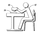
以下、添付図面を参照しながら本発明の実施例を説明する。図1〜3を参照して、ここには、文書カメラ10が示してあり、ユーザ12がこのカメラ10のファインダ・レンズを通して見る必要なく、着座したままで文書14の画像を取り込むことができる。
【0015】
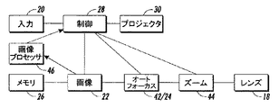
文書カメラ10は、ハウジング16からなり、このハウジングは、対物レンズ18と、カメラの動作を制御するための1つまたはそれ以上の操作ボタン20を収容している。カメラ10内には、画像を取り込むための光電検出器22と、後に行うOCRに適するように取り込まれた画像を鮮明にかつ確実に合焦させるオートフォーカス機構24と、取り込まれた画像を記憶するための記憶媒体26とが設けてある。これらの構成要素の構造は、カメラ製造業者にとって周知であるから、ここでは詳細に説明する必要はないであろう。カメラは、コントローラ28の制御の下に作動する。
【0016】
カメラ10は、目標フィールド、すなわち、取り込もうとしている文書14に視野インジケータ32を投射するための光学プロジェクタ30を備えている。視野インジケータ32は、文書それ自体の上で見ることができ(図2)、ユーザがカメラ・ファインダを通して文書を見る必要がなく、文書画像の所望ページまたは他の領域を取り込むようにカメラを正しく位置決めすることができる。たとえば、図2においては、文書14の下半分にあるテキスト34をカメラの視野によって取り囲むようにカメラを位置決めしている。
【0017】
視野インジケータ32は、多数の異なった形、たとえば、フレーム・コーナを示すマーカ、点線、グリッドあるいは領域全体照明の任意の形を採り得る。本実施例においては、視野境界を明白かつ明確に指示するために好ましいと考え、矩形の境界線を採用している。しかしながら、後述する変形実施例においては、グリッド・インジケータが好ましいと考えられる。
【0018】
視野インジケータ26を投射するために任意適当なプロジェクタ30を使用し得る。適当な構造については後述する。
【0019】
第1実施例において、カメラ10は、固定視野、すなわち、固定視野角を有する。カメラ10を文書撮像に適したモードに置いたとき、コントローラ28が、プロジェクタ30を制御して、視野インジケータ32を投射する。取り込もうとしている所望領域は、カメラを物理的に動かすことによって調節し、所望の画像を視野インジケータ32によって枠取りする。カメラのシャッタ・リリース・ボタンが押されると、コントローラ28はプロジェクタ30を制御して、視野インジケータ32を消去する。こうして、画像が、光検出器24によって取り込まれ、記憶媒体26へ転送される。
【0020】
図4、5を参照して、カメラの第2実施例を説明する。この実施例において同じ特徴を示すために同じ参照符号を使用する。この第2実施例は、第1実施例と同様であるが、ゾーン40a、40b、40cとして示す複数の異なった、所定の視野をカメラが有する点で異なっている。これらのゾーンは、文書の或る特定のセクションを取り込むための所定のページ・サイズまたは所定のセクション・サイズに対応している。第2実施例において、ユーザは、視野の所望サイズを選び、プロジェクタ30は、それぞれのゾーン40a、40bまたは40cを枠取りするように対応するインジケータ32を投射する。ここで、投射された視野インジケータ32のサイズがカメラ10の文書14からの距離に依存することはいうまでもない。従って、本実施例において、カメラは、距離測定装置42(たとえば、上記のオートフォーカス機構24の一部であり得る赤外測距計)を包含し、これが、文書のカメラからの距離を決定するのに用いられる。
【0021】
プロジェクタ30は、視野インジケータ32のサイズを変え得るようにコントローラ28によって制御可能である。コントローラ28は、カメラに対する文書の検出距離に基づいて所定のゾーン40a(または40bまたは40c)と一致するように視野インジケータの正しいサイズを決定する。したがって、視野インジケータ32がその距離で文書に投射されると、それはゾーンの所定サイズと一致することになる。
【0022】
ユーザがシャッタ・リリースを押し下げると、カメラ10は、視野インジケータによって示される領域の画像を取り込む。所望に応じて、カメラの光電検出器によって獲得した後に画像を切り取ることによって撮像領域を制御してもよい。しかしながら、本実施例においては、カメラ10は、さらに、カメラ・レンズ18を所望の視野にズームするためのズーム機構44を包含する。これにより、文書の選択された領域を最大解像度で取り込むことができる。いうまでもなく、取り込まれた画像の解像度が高ければ高いだけ、後の処理、たとえば、OCRにとって画像がより良好になる。
【0023】
図6〜8を参照して、ここには、カメラ10の第3実施例が示してある。ここで再び、先に説明したものに均等な特徴を示すために、必要に応じて同じ参照番号を使用する。本実施例においては、カメラは、第2実施例で説明したようなズーム機構44を包含する。カメラ10は、さらに、自動的に文書画像の完全なセグメントまたはゾーンの境界を検出するように文書画像を処理する画像プロセッサ46を包含する。このプロセッサ46の目的は、どのゾーンがカメラの視野に完全に入っているかを検出することにある。これらのゾーンは、視野の縁と重なっている(その結果、視野の外側に延びている)。
【0024】
このような処理の例が図6に示してある。ここでは、カメラの視野48は文書14に相対して示してある。第1のテキスト画像ゾーン50は、視野48内に完全に入っている。第2のテキスト画像ゾーン52は、視野48内にほんの部分的に入っている。第3ゾーン54は、視野48内に入っているブランク・マージン・ゾーンである。画像プロセッサ46の目的は、現視野内で得られる有用な文書画像を表すので、第1ゾーン50の境界を識別することである。
【0025】
画像プロセッサ46は、第1ゾーン50を検出するために任意の適当な検出アルゴリズムを使用できる。一般的に、検出は、処理を速くするために、視野内の低解像度画像を使用して実施される。好ましくは、検出アルゴリズムは、スキュー除去した文書ページを想定しない(すなわち、文書は、必ずしもカメラの矩形視野と整合している訳ではない)。さらに、アルゴリズムが、100dpiのオーダーの解像度で画像に迅速かつ確実に作用するように選ぶと好ましい。
【0026】
特に適切なアルゴリズムは、K. Kise, A. Sato and K. Matsumoto, "Document Image Segmentation as Selection of Voroni Edges", in Proc. Workshop on Document Image Analysis, Eds. L. Vincent and G. Kopec, San Juan, June 1997, pages 32-39に記載されている。このアルゴリズムからの出力は、テキスト・ブロックまたは図面または表を取り囲む閉じた(必ずしも凸面でない)多角形領域の集合である。次に、これらの領域が内向きに漸次浸食され、完全なブロックまたはゾーンだけが視野によって覆われ、不完全なブロックは切り取られる。
【0027】
図8は、画像を獲得するカメラの制御動作を示している。まず、ステップ60で、カメラは、画像を分析するための初期またはデフォルト・モードにセットされる。次に、ステップ62で、低解像度画像が光電検出器22によって獲得される。ステップ64で、低解像度画像が画像プロセッサ46によって処理され、カメラの最大視野(図7に関連して説明した)内に全体的に入る完全なテキスト、図面または表に対応するゾーンを識別する。これは、「取込みゾーン」と呼ぶ。ステップ66で、コントローラ28は、プロジェクタ30を制御して、取込みゾーン(すなわち、検出された完全なゾーン)を枠取りするように視野インジケータ32を投射する。
【0028】
次に、ステップ70で、作動が休止し、ユーザがシャッタ・リリース・ボタンを押すのを待つ。あるいは、シャッタ・リリース・ボタンが或る期間内で押されなかった場合には、または、カメラの移動が検出された場合には、作動はステップ62に戻る。カメラの移動は、光学的な変化(たとえば、画像の運動)あるいは加速度計によって検出され得る。
【0029】
ひとたびシャッタ・リリース・ボタンが押されたならば、コントローラ28がプロジェクタ30を制御してステップ72で視野インジケータ32を消去する。次に、ステップ74で、コントローラ28はズーム機構44を制御して取込みゾーンに向かってズームインする。ここで、取込みゾーンが軸から外れているかも知れず、その結果、ズーム機構44が取込みゾーン上に中心を合わせることができないことはいうまでもない。それにもかかわらず、カメラ・レンズをズームすることによって、現カメラ位置にとって最良の可能性ある解像度で画像を取り込むことが可能となる。
【0030】
ステップ76で、高解像度画像は、ズーミング後に光検出器22から獲得される。ステップ78で、切り取り操作が行われ、取込みゾーンの外側にある画像の任意領域を切り取る。このような領域は、たとえば、上述したように取込みゾーンが軸から外れている場合に存在し得る。切り取り後、画像は、取込みゾーンからの完全なテキスト・ブロックに一致する。次いで、この画像は、ステップ80で、カメラ記憶媒体26内に記憶される。
【0031】
ここで、この実施例が極めて融通の利く獲得動作を提供できることはいうまでもなかろう。画像は、そのどの領域全体を取り込み得るかを検出するように処理され、カメラは、その領域のみを、利用できる最良の解像度で取り込むようにズーム操作される。ユーザがカメラによって検出される取込みゾーンを変えたい場合には、文書が多少とも利用できる視野に入るようにカメラを動かすだけでよい。先の実施例におけると同様に、ユーザは、カメラ・ファインダを通して文書を見る必要はない。その代わりに、視野(または、本実施例においては、検出された取込みゾーン)が、文書それ自体の上に直接投射される。
【0032】
上記の実施例において、任意適当な形態のプロジェクタ30を使用して視野インジケータ32を投射することができる。プロジェクタ30のための光源は、レーザまたは白熱電球または蛍光灯であってよい。半導体レーザ・ソースが好ましい。これがコンパクトで、比較的強い出力ビームを発生することができるからである。
【0033】
図9を参照して、光は、たとえば、SLR(Single-Lens Reflex)カメラにおけるファインダ経路であり得るカメラの対物レンズ18を82で示すように通ってもよいし、画像センサ経路に沿って通ってもよい。この具体例は、ズーム機構(44)が使われた場合、表示領域がカメラのズーム設定に常に一致することになるという利点を有する。また、投射画像と視野との間には視差がまったくない。また、カメラが合焦しているときには、投射されたインジケータも合焦することになるという特性を有する。これは、安定したオートフォーカスを必要とするかも知れないが、同時に、カメラ・ファインダを通して見ていないときにフォーカスの状態についての情報をユーザが得ることができるという有用な方法でもある。
【0034】
あるいは、プロジェクタは、カメラの別部分(84で示す)に収容してもよいし、あるいは、たとえば、フラッシュ・ホルダ(86で示す)上に他のカメラ部分から便利して収容してもよい。このような具体例は、既存のカメラ設計の改造に適しているかも知れない。
【0035】
上記の先行特許は、ビームを整形し、制御する種々の選択肢を記載している。光源光は、また、制御可能な伝送媒体(たとえば、LCD)、制御可能な偏差媒体(たとえば、作動式円筒レンズ)または選択可能な固定伝送媒体(たとえば、フィルタ・ホイールから選んだ小型写真スライドまたはホログラム)を通すことにより制御され得る。あるいは、光源光は、急速移動ミラーで反射させ(或る種の公知のバーコード・リーダと同様)、残像性を使用して閉境界の効果を与えてもよい。
【0036】
前述の実施例において、プロジェクタ30は、画像取込みのためにはオフにする。しかしながら、視野インジケータ32を対象フィールドに投射している間に付加的な画像獲得を実施する(主画像取込み前)場合には、撮影しようとしている対象物についてのさらなる情報を獲得することができる。プロジェクタ30がカメラ・レンズの光軸からずれている場合(すなわち、プロジェクタがカメラ・レンズを通して画像を投射していない場合)には、これは特に有用である。適切なオフセット位置は、図9に84、86で示す位置である。それ故、プロジェクタ30とレンズ18の間には少なくとも或る程度の視差がある。この視差は、撮像しようとしている文書が平らであるかあるいはカメラに対して湾曲しているかどうか(すなわち、カメラに向かってあるいはカメラから離れるような弯曲)、あるいは、文書がカメラに対して斜めになっているかどうかを検出するのに使用することができる。このような湾曲および/またはスキューは、取り込まれた画像における対象物の光学的ひずみを生じさせるので重要である。スキューおよび/または湾曲によって、カメラで撮影されるときに視野インジケータ32に対する或る程度のひずみも生じるため、検出することができる。
【0037】
たとえば、図10では、本90を開いて2つの見開きページ92、94を示している。本の背は、ページをわずかに湾曲した形状にする(概略輪郭線96で示す)。図10において、カメラは、撮影している人間から見て、背後から見ているように示してある。カメラのプロジェクタ30は、カメラ本体より上方に取り付けてあり、したがって、カメラの対物レンズ98(および光軸100)からオフセットしている。プロジェクタ30とカメラの光軸100との間の視差は、光軸100に沿って見たときに、視野インジケータ32の外観を、それが投射された対象物の形状に従属させる。
【0038】
図示実施例においては、102で示すように、光軸に沿って見たとき、視野インジケータ32は、少量の湾曲によってゆがめられているように見える。したがって、視野インジケータ32が投射されている間に対象物の画像を獲得し、視野インジケータ32の既知の投射形状と獲得した形状102との間のひずみを検出することによって、既知の形状に一致するように獲得画像を「訂正する」ための訂正ファクタを決定することができる。この訂正ファクタは、カメラの見る画像における対象物(ならびに視野インジケータ)のひずみを除去するためのスキュー除去および/またはゆがみ除去ファクタである。
【0039】
ここで、湾曲量が空間的に変化する可能性があることはいうまでもない(図10参照)。本実施例においては、矩形フレーム形状の代わりに、矩形グリッドを視野インジケータ32として使用する。これは、カメラに相対的なページの弯曲およびスキューについてのより多くの空間情報を与えることができるので、好ましい。
【0040】
投射されたグリッド(視差効果を有する位置からの投射)によって照らされる対象物画像を獲得し、獲得画像における矩形形状からグリッドがひずんでいる程度を検出することによって、適切な訂正が行われ、画像におけるゆがみ除去、スキュー除去を行うことができる。
【0041】
この種の訂正技術に関するより多くの情報は、米国特許第5,835,241号、そしてまた、Doncescu A. et al, "Former Books Digital Processing: Image Warping", Proc. Workshop on Document Image Analysis, San Juan, Puerto Rico, June 20, 1997, Eds. L. Vincent & G. E. Kopecに見出せる。
【0042】
上記のスキュー除去および/またはゆがみ除去技術は、前述の実施例のいずれにおいても使用することができる。図9の実施例と関連して、1つまたはそれ以上の回数の獲得を行って訂正情報を得るようにしてもよい。たとえば、「取込みゾーン」の決定前に訂正獲得を行って判定のための最適情報を得るようにすると望ましいかも知れない。さらにまたは代わりに、主画像取込みの直前(ズーミング後)に訂正獲得を行って、ズーム画像についての最適な訂正情報を得ることも望ましいかも知れない。
【図面の簡単な説明】
【図1】ユーザが着座したまま文書を撮影しているところを示す概略図である。
【図2】本発明の第1実施例を示す、図1と同様の概略斜視図である。
【図3】第1実施例のカメラの概略ブロック図である。
【図4】本発明の第2実施例のページ・ゾーンを示す概略図である。
【図5】第2実施例のカメラの概略ブロック図である。
【図6】本発明の第3実施例のページ・ゾーンを示す概略図である。
【図7】第3実施例のカメラの概略ブロック図である。
【図8】第3実施例の動作を説明する概略フローチャートである。
【図9】視野プロジェクタの他の具体例を示す概略斜視図である。
【図10】投射された視野インジケータを使用して対象物の湾曲をカメラで検出してゆがみ除去を行う方法を例示している概略斜視図である。
【符号の説明】
10 文書カメラ
12 ユーザ
14 文書
16 ハウジング
18 対物レンズ
20 操作ボタン
22 光電検出器
24 オートフォーカス機構
26 記憶媒体
28 コントローラ
30 光学プロジェクタ
32 視野インジケータ
34 テキスト
40 ゾーン
42 距離測定装置
44 ズーム機構
46 画像プロセッサ
48 視野
50 第1テキスト画像ゾーン
52 第2テキスト画像ゾーン[0001]
BACKGROUND OF THE INVENTION
The present invention relates to the field of document cameras, and in particular to showing the effective field of view of document cameras. The present invention is particularly suitable for portable (eg, handheld) document cameras.
[0002]
[Prior art]
A document camera is defined herein as a digital camera having sufficient digital resolution to allow processing of a document image captured by an optical character recognition (OCR) algorithm. Thus, the resolution is equal to at least 100 dpi (dots / inch) of the original document.
[0003]
For example, to capture a single page image lying flat on a table, most digital cameras are designed to capture while the user is standing, and the user can see through the viewfinder and view It is necessary to choose. Therefore, since it is necessary to take an unnatural inclination posture that looks down on the page, it is inconvenient to see the page that the user is trying to capture through the finder while sitting. This is also inconvenient for those who wear glasses.
[0004]
Some digital cameras have a display for visual feedback, which increases the cost of the camera and is usually also fixed because the display is fixed to the back of the camera. Making it difficult for users to use. Some cameras have a foldable video display. However, since the viewpoint coordinate system is not the same as the user's viewpoint coordinate system, it is difficult to handle hand-eye coordinates. In addition, all electronic displays need to be able to keep the camera in focus as the user moves to obtain satisfactory visual feedback.
[0005]
A further problem with electronic displays is that if the user wants to capture a small section of the document in zooming mode, he must know exactly what the document screen the user is currently viewing is related to the area he wants to capture. That's it.
[0006]
In the general camera field, a camera having a projector that projects a light source onto a screen on which the light source is to be captured and gives a boundary marker indicating the field of view of the light source has been proposed. This eliminates the need for the user to look through the viewfinder because the field of view is shown on the target screen. This light source may be, for example, a semiconductor laser. See U.S. Pat. Nos. 5,589,905, 5,500,702 and 5,485,235. However, these configurations are not intended for document cameras and do not solve any problems inherent in this field of image capture.
[0007]
Furthermore, U.S. Pat. Nos. 5,189,463, 5,628,034, 5,546,156, 5,543,889, 5,666,577 and See 5,835,241.
[0008]
[Problems to be solved by the invention]
It would be desirable to have a document camera that can be used more conveniently while the user is seated without the need for a viewfinder.
[0009]
It would also be desirable if a variable field of view for a document camera could be shown.
[0010]
[Means for Solving the Problems]
In a broad sense, a first aspect of the present invention is to provide a document camera that includes a projector that projects an indicator onto a target screen that is about to be captured, the indicator showing the field of view of the camera.
[0011]
This allows the operator to see the field of view on the document itself without having to look through a camera finder that may be inconvenient.
[0012]
In a preferred form, the projector is operable to project the field indicator to have a variable size and / or position. The camera includes a controller for controlling the size and / or position of the projected field indicator to change its field of view.
[0013]
In a particularly preferred form, the camera includes an image processor that processes at least a partially captured image to detect an optimal capture zone for the document. This capture zone coincides with the entire section or region of the document that falls within the camera's available field of view. Any section that does not fall completely within the available field of view is considered not included in the captured image. The projected field indicator is then controlled to show only the capture zone. When attempting to capture an image, the camera is zoomed in and the image area corresponding to the capture zone is captured at maximum (or at least enlarged) resolution.
[0014]
DETAILED DESCRIPTION OF THE INVENTION
Embodiments of the present invention will be described below with reference to the accompanying drawings. 1-3, a
[0015]
The
[0016]
The
[0017]
The
[0018]
Any
[0019]
In the first embodiment, the
[0020]
A second embodiment of the camera will be described with reference to FIGS. The same reference numerals are used to indicate the same features in this embodiment. This second embodiment is similar to the first embodiment, but differs in that the camera has a plurality of different, predetermined fields of view shown as
[0021]
The
[0022]
When the user depresses the shutter release, the
[0023]
6 to 8, a third embodiment of the
[0024]
An example of such processing is shown in FIG. Here, the field of
[0025]
The
[0026]
A particularly suitable algorithm is K. Kise, A. Sato and K. Matsumoto, "Document Image Segmentation as Selection of Voroni Edges", in Proc. Workshop on Document Image Analysis, Eds. L. Vincent and G. Kopec, San Juan , June 1997, pages 32-39. The output from this algorithm is a collection of closed (not necessarily convex) polygonal regions that surround a text block or drawing or table. These regions are then gradually eroded inward, only complete blocks or zones are covered by the field of view, and incomplete blocks are cut off.
[0027]
FIG. 8 shows a control operation of the camera for acquiring an image. First, at
[0028]
Next, at
[0029]
Once the shutter release button has been pressed, the
[0030]
At
[0031]
Here, it goes without saying that this embodiment can provide a very flexible acquisition operation. The image is processed to detect which entire area can be captured, and the camera is zoomed to capture only that area at the best available resolution. If the user wants to change the capture zone detected by the camera, he only needs to move the camera so that the document is in a more or less usable field of view. As in the previous embodiment, the user does not need to view the document through the camera finder. Instead, the field of view (or, in this example, the detected capture zone) is projected directly onto the document itself.
[0032]
In the above embodiments, the
[0033]
Referring to FIG. 9, the light may pass through the
[0034]
Alternatively, the projector may be housed in another part of the camera (indicated by 84) or conveniently housed from another camera part, for example, on a flash holder (indicated by 86). Such an embodiment may be suitable for retrofitting existing camera designs.
[0035]
The above prior patents describe various options for shaping and controlling the beam. The source light can also be a controllable transmission medium (eg LCD), a controllable deviation medium (eg actuated cylindrical lens) or a selectable fixed transmission medium (eg a small photographic slide selected from a filter wheel or Can be controlled by passing through a hologram. Alternatively, the source light may be reflected by a fast moving mirror (similar to some known bar code readers) and afterimage properties may be used to provide a closed boundary effect.
[0036]
In the embodiment described above, the
[0037]
For example, in FIG. 10, the
[0038]
In the illustrated embodiment, the
[0039]
Here, it goes without saying that the amount of bending may vary spatially (see FIG. 10). In this embodiment, a rectangular grid is used as the
[0040]
Appropriate correction is performed by acquiring an object image illuminated by the projected grid (projection from a position having a parallax effect) and detecting the degree of distortion of the grid from the rectangular shape in the acquired image. It is possible to perform distortion removal and skew removal.
[0041]
More information on this type of correction technique can be found in US Pat. No. 5,835,241 and also Doncescu A. et al, “Former Books Digital Processing: Image Warping”, Proc. Workshop on Document Image Analysis, San Can be found in Juan, Puerto Rico, June 20, 1997, Eds. L. Vincent & GE Kopec.
[0042]
The above skew removal and / or distortion removal techniques can be used in any of the previous embodiments. In connection with the embodiment of FIG. 9, correction information may be obtained by obtaining one or more times. For example, it may be desirable to obtain corrections to obtain optimal information for determination prior to determination of a “capture zone”. Additionally or alternatively, it may be desirable to perform correction acquisition immediately before main image capture (after zooming) to obtain optimal correction information for the zoomed image.
[Brief description of the drawings]
FIG. 1 is a schematic diagram showing a user shooting a document while sitting.
FIG. 2 is a schematic perspective view similar to FIG. 1, showing a first embodiment of the present invention.
FIG. 3 is a schematic block diagram of the camera of the first embodiment.
FIG. 4 is a schematic diagram showing a page zone of a second embodiment of the present invention.
FIG. 5 is a schematic block diagram of a camera of a second embodiment.
FIG. 6 is a schematic diagram showing a page zone according to a third embodiment of the present invention.
FIG. 7 is a schematic block diagram of a camera of a third embodiment.
FIG. 8 is a schematic flowchart for explaining the operation of the third embodiment.
FIG. 9 is a schematic perspective view showing another specific example of a visual field projector.
FIG. 10 is a schematic perspective view illustrating a method of performing distortion removal by detecting the curvature of an object with a camera using a projected field indicator.
[Explanation of symbols]
DESCRIPTION OF
Claims (3)
ズーム機構を有するレンズと、
前記レンズによって撮像された、文書の第1電子画像を取り込む光検出器と、
光検出器によって取り込まれた前記第1電子画像を処理する画像処理装置とを備え、
前記画像処理装置は、前記第1電子画像内に1つの取込みゾーンを決定しており、前記取込みゾーンは、前記第1電子画像内において1つ若しくはそれ以上の完全なゾーンを識別しており、
更に、前記取込みゾーンを識別する、視野インジケータを、前記レンズによって撮像された文書上へ投射してユーザが前記文書上の前記視野インジケータを見えるようにするプロジェクタと、
前記ズーム機構を、前記視野インジケータによって識別された前記取込みゾーンの第2電子画像を取り込むように制御するコントローラとを備え、前記第2電子画像は、前記第1電子画像より高い解像度で前記取込みゾーンを記録している、
ことを特徴とする文書カメラ。A document camera,
A lens having a zoom mechanism;
A photodetector for capturing a first electronic image of the document imaged by the lens;
An image processing device for processing the first electronic image captured by a photodetector;
The image processing device has determined one capture zone in the first electronic image, the capture zone identifying one or more complete zones in the first electronic image;
A projector that projects a field indicator that identifies the capture zone onto a document imaged by the lens so that a user can view the field indicator on the document;
A controller for controlling the zoom mechanism to capture a second electronic image of the capture zone identified by the field indicator, wherein the second electronic image is at a higher resolution than the first electronic image. Recording,
Document camera characterized by that.
対物レンズと、
前記対物レンズによって撮像された、文書の電子画像を取り込む光検出器と、
前記レンズによって撮像された文書に視野インジケータを投射してユーザが前記文書上の前記視野インジケータを見えるようにするためのプロジェクタとを備え、該プロジェクタは、前記視野インジケータを可変のサイズと位置で投射するよう構成されており、
更に、前記プロジェクタによって投射された視野インジケータの投射サイズと位置を制御するコントローラと、
前記画像内に取込みゾーンを決定するように、前記光検出器から画像出力を処理する画像処理装置とを備え、
前記取込みゾーンを表示するために、前記コントローラは、前記投射された視野インジケータの位置とサイズを制御するように前記画像処理装置に応答する、
ことを特徴とする文書カメラ。A document camera,
An objective lens;
A photodetector for capturing an electronic image of the document imaged by the objective lens;
A projector for projecting a field indicator on a document imaged by the lens to allow a user to view the field indicator on the document, the projector projecting the field indicator in a variable size and position Configured to
A controller for controlling the projection size and position of the field indicator projected by the projector;
An image processing device for processing an image output from the photodetector so as to determine a capture zone in the image;
To display the capture zone, the controller is responsive to the image processing device to control the position and size of the projected field indicator.
Document camera characterized by that.
対物レンズと、
前記対物レンズによって撮像された、文書の電子画像を取り込む光検出器と、
前記レンズによって撮像された文書に視野インジケータを投射してユーザが前記文書上の前記視野インジケータを見えるようにするためのプロジェクタとを備え、該プロジェクタは、該プロジェクタから発した前記視野インジケータのサイズを、前記撮像された文書上で調整する、調整可能な光学手段を包含し、
更に、前記プロジェクタの前記調整可能な光学手段を制御するコントロール回路と、
前記文書から前記カメラまでの距離を測定する距離測定装置とを備え、
前記コントロール回路は、前記距離測定装置に応答して前記光学手段を制御するように動作して、前記プロジェクタから投射された視野インジケータのサイズを、前記測定した距離に基づいて、前記視野インジケータの文書上への投射が所定サイズであるように調整する、
ことを特徴とする文書カメラ。A document camera,
An objective lens;
A photodetector for capturing an electronic image of the document imaged by the objective lens;
A projector for projecting a field indicator onto a document imaged by the lens so that a user can view the field indicator on the document, the projector having a size of the field indicator emitted from the projector Including adjustable optical means for adjusting on the imaged document;
A control circuit for controlling the adjustable optical means of the projector;
A distance measuring device for measuring a distance from the document to the camera;
The control circuit is operative to control the optical means in response to the distance measuring device, and determines a size of the field indicator projected from the projector based on the measured distance. Adjust so that the projection on top is a predetermined size,
Document camera characterized by that.
Applications Claiming Priority (2)
| Application Number | Priority Date | Filing Date | Title |
|---|---|---|---|
| US09/707,930 US6463220B1 (en) | 2000-11-08 | 2000-11-08 | Method and apparatus for indicating a field of view for a document camera |
| US09/707930 | 2000-11-08 |
Publications (3)
| Publication Number | Publication Date |
|---|---|
| JP2002223381A JP2002223381A (en) | 2002-08-09 |
| JP2002223381A5 JP2002223381A5 (en) | 2005-07-07 |
| JP3929752B2 true JP3929752B2 (en) | 2007-06-13 |
Family
ID=24843718
Family Applications (1)
| Application Number | Title | Priority Date | Filing Date |
|---|---|---|---|
| JP2001336597A Expired - Fee Related JP3929752B2 (en) | 2000-11-08 | 2001-11-01 | Document camera |
Country Status (4)
| Country | Link |
|---|---|
| US (1) | US6463220B1 (en) |
| EP (2) | EP1453297B1 (en) |
| JP (1) | JP3929752B2 (en) |
| DE (2) | DE60105942T2 (en) |
Families Citing this family (56)
| Publication number | Priority date | Publication date | Assignee | Title |
|---|---|---|---|---|
| US6975352B2 (en) * | 2000-12-18 | 2005-12-13 | Xerox Corporation | Apparatus and method for capturing a composite digital image with regions of varied focus and magnification |
| US20040218069A1 (en) * | 2001-03-30 | 2004-11-04 | Silverstein D Amnon | Single image digital photography with structured light for document reconstruction |
| US20030151666A1 (en) * | 2002-02-13 | 2003-08-14 | Modest Khovaylo | Imaging apparatus with mouse pad |
| JP2004297751A (en) * | 2003-02-07 | 2004-10-21 | Sharp Corp | Focusing state display device and focusing state display method |
| US20050097046A1 (en) | 2003-10-30 | 2005-05-05 | Singfield Joy S. | Wireless electronic check deposit scanning and cashing machine with web-based online account cash management computer application system |
| WO2006033360A1 (en) | 2004-09-21 | 2006-03-30 | Nikon Corporation | Mobile information device |
| US7050084B1 (en) * | 2004-09-24 | 2006-05-23 | Avaya Technology Corp. | Camera frame display |
| GB2419760A (en) * | 2004-11-01 | 2006-05-03 | Citysync Ltd | Image capture system with alignment and character recognition means |
| KR100618160B1 (en) * | 2004-12-07 | 2006-08-29 | 씨씨알 주식회사 | FL GRID transmission Camera Device |
| US7706576B1 (en) | 2004-12-28 | 2010-04-27 | Avaya Inc. | Dynamic video equalization of images using face-tracking |
| US7460150B1 (en) | 2005-03-14 | 2008-12-02 | Avaya Inc. | Using gaze detection to determine an area of interest within a scene |
| KR100689384B1 (en) * | 2005-03-21 | 2007-03-02 | 삼성전자주식회사 | Mobile communication terminal having camera function and method thereof |
| US20070269109A1 (en) * | 2005-03-23 | 2007-11-22 | Jakob Ziv-El | Method and apparatus for processing selected images on image reproduction machines |
| US7564476B1 (en) | 2005-05-13 | 2009-07-21 | Avaya Inc. | Prevent video calls based on appearance |
| US20070127909A1 (en) | 2005-08-25 | 2007-06-07 | Craig Mowry | System and apparatus for increasing quality and efficiency of film capture and methods of use thereof |
| FI20055365A (en) * | 2005-06-29 | 2006-12-30 | Nokia Corp | Method, device and program product for displaying a selected object visually with a camera-equipped device |
| GB2435525A (en) * | 2006-02-24 | 2007-08-29 | Jonathan Bradley | A viewfinder unit for a camera |
| GB0609316D0 (en) * | 2006-05-11 | 2006-06-21 | South Bank Univ Entpr Ltd | Underwater mask |
| US8165282B1 (en) | 2006-05-25 | 2012-04-24 | Avaya Inc. | Exploiting facial characteristics for improved agent selection |
| JP2008009572A (en) * | 2006-06-27 | 2008-01-17 | Fuji Xerox Co Ltd | Document processing system, document processing method, and program |
| US7873200B1 (en) | 2006-10-31 | 2011-01-18 | United Services Automobile Association (Usaa) | Systems and methods for remote deposit of checks |
| US8708227B1 (en) | 2006-10-31 | 2014-04-29 | United Services Automobile Association (Usaa) | Systems and methods for remote deposit of checks |
| US20080112700A1 (en) * | 2006-11-13 | 2008-05-15 | Foxenland Eral D | Imaging device with projected viewfinder |
| US9538036B2 (en) | 2007-01-30 | 2017-01-03 | Hewlett-Packard Development Company, L.P. | Scan area indication |
| US10380559B1 (en) | 2007-03-15 | 2019-08-13 | United Services Automobile Association (Usaa) | Systems and methods for check representment prevention |
| US7729600B2 (en) * | 2007-03-19 | 2010-06-01 | Ricoh Co. Ltd. | Tilt-sensitive camera projected viewfinder |
| US9058512B1 (en) | 2007-09-28 | 2015-06-16 | United Services Automobile Association (Usaa) | Systems and methods for digital signature detection |
| US9898778B1 (en) | 2007-10-23 | 2018-02-20 | United Services Automobile Association (Usaa) | Systems and methods for obtaining an image of a check to be deposited |
| US9159101B1 (en) | 2007-10-23 | 2015-10-13 | United Services Automobile Association (Usaa) | Image processing |
| US9892454B1 (en) | 2007-10-23 | 2018-02-13 | United Services Automobile Association (Usaa) | Systems and methods for obtaining an image of a check to be deposited |
| US20090182548A1 (en) * | 2008-01-16 | 2009-07-16 | Jan Scott Zwolinski | Handheld dictionary and translation apparatus |
| US10380562B1 (en) | 2008-02-07 | 2019-08-13 | United Services Automobile Association (Usaa) | Systems and methods for mobile deposit of negotiable instruments |
| US10504185B1 (en) | 2008-09-08 | 2019-12-10 | United Services Automobile Association (Usaa) | Systems and methods for live video financial deposit |
| KR20100064533A (en) * | 2008-12-05 | 2010-06-15 | 삼성전자주식회사 | Apparatus and method for automatic character resizing using camera |
| US10956728B1 (en) | 2009-03-04 | 2021-03-23 | United Services Automobile Association (Usaa) | Systems and methods of check processing with background removal |
| US9779392B1 (en) | 2009-08-19 | 2017-10-03 | United Services Automobile Association (Usaa) | Apparatuses, methods and systems for a publishing and subscribing platform of depositing negotiable instruments |
| US8977571B1 (en) * | 2009-08-21 | 2015-03-10 | United Services Automobile Association (Usaa) | Systems and methods for image monitoring of check during mobile deposit |
| US8699779B1 (en) | 2009-08-28 | 2014-04-15 | United Services Automobile Association (Usaa) | Systems and methods for alignment of check during mobile deposit |
| CN101815126A (en) * | 2010-03-19 | 2010-08-25 | 中兴通讯股份有限公司 | Method and device for automatically adjusting display scale |
| US9129340B1 (en) | 2010-06-08 | 2015-09-08 | United Services Automobile Association (Usaa) | Apparatuses, methods and systems for remote deposit capture with enhanced image detection |
| US20120072280A1 (en) | 2010-09-20 | 2012-03-22 | Lin Jennifer W | Tracking Conversions |
| JP4918167B1 (en) * | 2011-03-31 | 2012-04-18 | パナソニック株式会社 | Image processing apparatus and document reading system having the same |
| US10210602B2 (en) | 2011-10-17 | 2019-02-19 | Sharp Laboratories Of America, Inc. | System and method for normalized focal length profiling |
| US10380565B1 (en) | 2012-01-05 | 2019-08-13 | United Services Automobile Association (Usaa) | System and method for storefront bank deposits |
| JPWO2014038093A1 (en) * | 2012-09-10 | 2016-08-08 | パイオニア株式会社 | Lighting device with drawing function |
| US10552810B1 (en) | 2012-12-19 | 2020-02-04 | United Services Automobile Association (Usaa) | System and method for remote deposit of financial instruments |
| JP6044426B2 (en) * | 2013-04-02 | 2016-12-14 | 富士通株式会社 | Information operation display system, display program, and display method |
| US11138578B1 (en) | 2013-09-09 | 2021-10-05 | United Services Automobile Association (Usaa) | Systems and methods for remote deposit of currency |
| US9286514B1 (en) | 2013-10-17 | 2016-03-15 | United Services Automobile Association (Usaa) | Character count determination for a digital image |
| KR20150115455A (en) | 2014-04-04 | 2015-10-14 | 삼성전자주식회사 | Method and apparatus for controlling projector focus in portable device |
| US10402790B1 (en) | 2015-05-28 | 2019-09-03 | United Services Automobile Association (Usaa) | Composing a focused document image from multiple image captures or portions of multiple image captures |
| US9578221B1 (en) | 2016-01-05 | 2017-02-21 | International Business Machines Corporation | Camera field of view visualizer |
| US11030752B1 (en) | 2018-04-27 | 2021-06-08 | United Services Automobile Association (Usaa) | System, computing device, and method for document detection |
| CN109302601B (en) * | 2018-10-15 | 2021-04-02 | 张家港康得新光电材料有限公司 | Testing method and testing device for naked eye 3D display screen |
| TWI738098B (en) * | 2019-10-28 | 2021-09-01 | 阿丹電子企業股份有限公司 | Optical volume-measuring device |
| US11900755B1 (en) | 2020-11-30 | 2024-02-13 | United Services Automobile Association (Usaa) | System, computing device, and method for document detection and deposit processing |
Family Cites Families (18)
| Publication number | Priority date | Publication date | Assignee | Title |
|---|---|---|---|---|
| GB9102873D0 (en) | 1991-02-12 | 1991-03-27 | Wheelan Ian | Torch & camera assembly |
| KR0137861B1 (en) * | 1991-07-15 | 1998-05-15 | 강진구 | Circuit for confirming shooting dimension by laser beam |
| US5189463A (en) | 1992-02-12 | 1993-02-23 | David G. Capper | Camera aiming mechanism and method |
| US5546156A (en) | 1994-02-25 | 1996-08-13 | Eastman Kodak Company | Camera with pointing aid |
| US5543889A (en) | 1994-05-16 | 1996-08-06 | Eastman Kodak Company | Camera with pointing aid |
| US5485235A (en) | 1994-05-19 | 1996-01-16 | Eastman Kodak Company | Pointing system for correctly aiming an image recording apparatus towards a human subject |
| US5500702A (en) | 1994-05-27 | 1996-03-19 | Eastman Kodak Company | Device for identifying a perimeter of a scene to be recorded by an image recording apparatus |
| US5589905A (en) | 1995-01-24 | 1996-12-31 | Eastman Kodak Company | Camera with illumination source |
| US5892543A (en) | 1995-06-05 | 1999-04-06 | United Parcel Service Of America, Inc. | Imaging system including an auto zoom controller |
| NL1000701C2 (en) * | 1995-06-30 | 1996-12-31 | Oce Nederland Bv | Device and method for extracting articles from a document. |
| US5666577A (en) | 1995-08-31 | 1997-09-09 | Eastman Kodak Company | System for switching pointing indices in laser aimed cameras |
| US5628034A (en) | 1996-02-27 | 1997-05-06 | Eastman Kodak Company | Image recording apparatus with movement detector and laser emitter |
| US5835241A (en) | 1996-05-30 | 1998-11-10 | Xerox Corporation | Method for determining the profile of a bound document with structured light |
| GB9614837D0 (en) | 1996-07-12 | 1996-09-04 | Rank Xerox Ltd | Interactive desktop system with multiple image capture and display modes |
| US5995661A (en) * | 1997-10-08 | 1999-11-30 | Hewlett-Packard Company | Image boundary detection for a scanned image |
| US6741279B1 (en) * | 1998-07-21 | 2004-05-25 | Hewlett-Packard Development Company, L.P. | System and method for capturing document orientation information with a digital camera |
| EP1022608A1 (en) * | 1999-01-21 | 2000-07-26 | Hewlett-Packard Company | Camera with projection viewfinder |
| DE19912254A1 (en) * | 1999-03-18 | 2000-09-21 | Tom Faehrmann | Device for indicating the edges of a picture or scene that is being filmed or shot on camera, has a projector that produces a laser beam that adjusts to the camera image format and focal length to outline the scene being shot |
-
2000
- 2000-11-08 US US09/707,930 patent/US6463220B1/en not_active Expired - Lifetime
-
2001
- 2001-11-01 JP JP2001336597A patent/JP3929752B2/en not_active Expired - Fee Related
- 2001-11-06 DE DE60105942T patent/DE60105942T2/en not_active Expired - Lifetime
- 2001-11-06 EP EP04012976A patent/EP1453297B1/en not_active Expired - Lifetime
- 2001-11-06 DE DE60117302T patent/DE60117302T2/en not_active Expired - Lifetime
- 2001-11-06 EP EP01125489A patent/EP1205790B1/en not_active Expired - Lifetime
Also Published As
| Publication number | Publication date |
|---|---|
| DE60117302D1 (en) | 2006-04-20 |
| US6463220B1 (en) | 2002-10-08 |
| DE60105942T2 (en) | 2005-10-13 |
| EP1205790A2 (en) | 2002-05-15 |
| JP2002223381A (en) | 2002-08-09 |
| DE60117302T2 (en) | 2006-11-09 |
| EP1453297A1 (en) | 2004-09-01 |
| EP1205790B1 (en) | 2004-09-29 |
| EP1205790A3 (en) | 2002-12-18 |
| DE60105942D1 (en) | 2004-11-04 |
| EP1453297B1 (en) | 2006-02-15 |
Similar Documents
| Publication | Publication Date | Title |
|---|---|---|
| JP3929752B2 (en) | Document camera | |
| US8102465B2 (en) | Photographing apparatus and photographing method for photographing an image by controlling light irradiation on a subject | |
| JP4553346B2 (en) | Focus adjustment device and focus adjustment method | |
| US6516151B2 (en) | Camera projected viewfinder | |
| JP4432886B2 (en) | Electronic camera | |
| JP2006211139A (en) | Imaging apparatus | |
| JP2003046844A (en) | Highlighting method, camera, and focus highlighting system | |
| JP2007281760A (en) | Electronic camera | |
| JP2010252312A (en) | In-camera generation of high-quality composite panoramic image | |
| JP2005159856A (en) | Digital camera | |
| JP2010226157A (en) | Camera, and image correction method | |
| EP1022608A1 (en) | Camera with projection viewfinder | |
| JP2008205569A (en) | Imaging apparatus and method | |
| JP2007150602A (en) | Electronic camera | |
| JP2005033766A (en) | Method and apparatus for automatically post-processing digital image | |
| JP2004208089A (en) | Projector, imaging device, and program for trapezoid correction | |
| JP2008076981A (en) | Electronic camera | |
| JP2003289468A (en) | Imaging apparatus | |
| TW201236448A (en) | Auto-focusing camera and method for automatically focusing of the camera | |
| JP5104517B2 (en) | Imaging device | |
| JPH05328197A (en) | Image pickup device | |
| KR20050051748A (en) | Method for photograph service of kiosk using pan tilt camera and computer readable record medium on which program therefor is recorded | |
| JPH07140373A (en) | Image input device | |
| JP2012027302A (en) | Imaging apparatus with projection function | |
| JP3197335B2 (en) | Camera that enables suitable close-up photography |
Legal Events
| Date | Code | Title | Description |
|---|---|---|---|
| A521 | Request for written amendment filed |
Free format text: JAPANESE INTERMEDIATE CODE: A523 Effective date: 20041101 |
|
| A621 | Written request for application examination |
Free format text: JAPANESE INTERMEDIATE CODE: A621 Effective date: 20041101 |
|
| A977 | Report on retrieval |
Free format text: JAPANESE INTERMEDIATE CODE: A971007 Effective date: 20060809 |
|
| A131 | Notification of reasons for refusal |
Free format text: JAPANESE INTERMEDIATE CODE: A131 Effective date: 20060904 |
|
| A521 | Request for written amendment filed |
Free format text: JAPANESE INTERMEDIATE CODE: A523 Effective date: 20061204 |
|
| TRDD | Decision of grant or rejection written | ||
| A01 | Written decision to grant a patent or to grant a registration (utility model) |
Free format text: JAPANESE INTERMEDIATE CODE: A01 Effective date: 20070205 |
|
| A61 | First payment of annual fees (during grant procedure) |
Free format text: JAPANESE INTERMEDIATE CODE: A61 Effective date: 20070307 |
|
| R150 | Certificate of patent or registration of utility model |
Free format text: JAPANESE INTERMEDIATE CODE: R150 |
|
| FPAY | Renewal fee payment (event date is renewal date of database) |
Free format text: PAYMENT UNTIL: 20110316 Year of fee payment: 4 |
|
| FPAY | Renewal fee payment (event date is renewal date of database) |
Free format text: PAYMENT UNTIL: 20110316 Year of fee payment: 4 |
|
| FPAY | Renewal fee payment (event date is renewal date of database) |
Free format text: PAYMENT UNTIL: 20120316 Year of fee payment: 5 |
|
| FPAY | Renewal fee payment (event date is renewal date of database) |
Free format text: PAYMENT UNTIL: 20130316 Year of fee payment: 6 |
|
| FPAY | Renewal fee payment (event date is renewal date of database) |
Free format text: PAYMENT UNTIL: 20140316 Year of fee payment: 7 |
|
| R250 | Receipt of annual fees |
Free format text: JAPANESE INTERMEDIATE CODE: R250 |
|
| R250 | Receipt of annual fees |
Free format text: JAPANESE INTERMEDIATE CODE: R250 |
|
| R250 | Receipt of annual fees |
Free format text: JAPANESE INTERMEDIATE CODE: R250 |
|
| LAPS | Cancellation because of no payment of annual fees |