JP3927711B2 - Method for manufacturing liquid discharge head - Google Patents
Method for manufacturing liquid discharge head Download PDFInfo
- Publication number
- JP3927711B2 JP3927711B2 JP34607498A JP34607498A JP3927711B2 JP 3927711 B2 JP3927711 B2 JP 3927711B2 JP 34607498 A JP34607498 A JP 34607498A JP 34607498 A JP34607498 A JP 34607498A JP 3927711 B2 JP3927711 B2 JP 3927711B2
- Authority
- JP
- Japan
- Prior art keywords
- movable member
- liquid
- gap forming
- forming
- discharge head
- Prior art date
- Legal status (The legal status is an assumption and is not a legal conclusion. Google has not performed a legal analysis and makes no representation as to the accuracy of the status listed.)
- Expired - Fee Related
Links
- 239000007788 liquid Substances 0.000 title claims description 207
- 238000004519 manufacturing process Methods 0.000 title claims description 38
- 238000000034 method Methods 0.000 title claims description 31
- 239000000758 substrate Substances 0.000 claims description 68
- 238000010438 heat treatment Methods 0.000 claims description 44
- 239000000463 material Substances 0.000 claims description 31
- 229910052581 Si3N4 Inorganic materials 0.000 claims description 13
- 238000005530 etching Methods 0.000 claims description 13
- HQVNEWCFYHHQES-UHFFFAOYSA-N silicon nitride Chemical compound N12[Si]34N5[Si]62N3[Si]51N64 HQVNEWCFYHHQES-UHFFFAOYSA-N 0.000 claims description 13
- 238000000059 patterning Methods 0.000 claims description 11
- 238000011144 upstream manufacturing Methods 0.000 claims description 10
- VYPSYNLAJGMNEJ-UHFFFAOYSA-N Silicium dioxide Chemical compound O=[Si]=O VYPSYNLAJGMNEJ-UHFFFAOYSA-N 0.000 claims description 8
- 229910052814 silicon oxide Inorganic materials 0.000 claims description 8
- 239000002210 silicon-based material Substances 0.000 claims description 6
- 238000012545 processing Methods 0.000 claims description 5
- 238000007599 discharging Methods 0.000 claims description 4
- HBMJWWWQQXIZIP-UHFFFAOYSA-N silicon carbide Chemical compound [Si+]#[C-] HBMJWWWQQXIZIP-UHFFFAOYSA-N 0.000 claims description 3
- 229910010271 silicon carbide Inorganic materials 0.000 claims description 3
- 238000011161 development Methods 0.000 claims description 2
- 238000002844 melting Methods 0.000 claims description 2
- 230000008018 melting Effects 0.000 claims description 2
- 239000010408 film Substances 0.000 description 55
- 239000010410 layer Substances 0.000 description 38
- ORQBXQOJMQIAOY-UHFFFAOYSA-N nobelium Chemical compound [No] ORQBXQOJMQIAOY-UHFFFAOYSA-N 0.000 description 9
- 238000007747 plating Methods 0.000 description 9
- XUIMIQQOPSSXEZ-UHFFFAOYSA-N Silicon Chemical compound [Si] XUIMIQQOPSSXEZ-UHFFFAOYSA-N 0.000 description 8
- 229910052710 silicon Inorganic materials 0.000 description 8
- 239000010703 silicon Substances 0.000 description 8
- 238000010586 diagram Methods 0.000 description 7
- 239000011241 protective layer Substances 0.000 description 7
- PXHVJJICTQNCMI-UHFFFAOYSA-N Nickel Chemical compound [Ni] PXHVJJICTQNCMI-UHFFFAOYSA-N 0.000 description 6
- 230000000694 effects Effects 0.000 description 5
- 238000005187 foaming Methods 0.000 description 5
- NJPPVKZQTLUDBO-UHFFFAOYSA-N novaluron Chemical compound C1=C(Cl)C(OC(F)(F)C(OC(F)(F)F)F)=CC=C1NC(=O)NC(=O)C1=C(F)C=CC=C1F NJPPVKZQTLUDBO-UHFFFAOYSA-N 0.000 description 5
- 239000004065 semiconductor Substances 0.000 description 5
- KRHYYFGTRYWZRS-UHFFFAOYSA-N Fluorane Chemical compound F KRHYYFGTRYWZRS-UHFFFAOYSA-N 0.000 description 4
- 230000015572 biosynthetic process Effects 0.000 description 4
- 229910052751 metal Inorganic materials 0.000 description 4
- 239000002184 metal Substances 0.000 description 4
- 230000008569 process Effects 0.000 description 4
- 239000002023 wood Substances 0.000 description 4
- 229910052782 aluminium Inorganic materials 0.000 description 3
- XAGFODPZIPBFFR-UHFFFAOYSA-N aluminium Chemical compound [Al] XAGFODPZIPBFFR-UHFFFAOYSA-N 0.000 description 3
- 230000008859 change Effects 0.000 description 3
- 239000010985 leather Substances 0.000 description 3
- 229910052759 nickel Inorganic materials 0.000 description 3
- 239000004033 plastic Substances 0.000 description 3
- 229910052715 tantalum Inorganic materials 0.000 description 3
- GUVRBAGPIYLISA-UHFFFAOYSA-N tantalum atom Chemical compound [Ta] GUVRBAGPIYLISA-UHFFFAOYSA-N 0.000 description 3
- 230000009471 action Effects 0.000 description 2
- 238000009835 boiling Methods 0.000 description 2
- 229910010293 ceramic material Inorganic materials 0.000 description 2
- 238000006073 displacement reaction Methods 0.000 description 2
- 239000004744 fabric Substances 0.000 description 2
- 238000005338 heat storage Methods 0.000 description 2
- 238000009413 insulation Methods 0.000 description 2
- 239000007769 metal material Substances 0.000 description 2
- 230000001681 protective effect Effects 0.000 description 2
- 238000001454 recorded image Methods 0.000 description 2
- 230000004044 response Effects 0.000 description 2
- 238000004528 spin coating Methods 0.000 description 2
- 239000013589 supplement Substances 0.000 description 2
- 230000002195 synergetic effect Effects 0.000 description 2
- 239000004753 textile Substances 0.000 description 2
- 238000001039 wet etching Methods 0.000 description 2
- 229910000838 Al alloy Inorganic materials 0.000 description 1
- 235000017166 Bambusa arundinacea Nutrition 0.000 description 1
- 235000017491 Bambusa tulda Nutrition 0.000 description 1
- 241001330002 Bambuseae Species 0.000 description 1
- RYGMFSIKBFXOCR-UHFFFAOYSA-N Copper Chemical compound [Cu] RYGMFSIKBFXOCR-UHFFFAOYSA-N 0.000 description 1
- 235000015334 Phyllostachys viridis Nutrition 0.000 description 1
- 239000004642 Polyimide Substances 0.000 description 1
- LRTTZMZPZHBOPO-UHFFFAOYSA-N [B].[B].[Hf] Chemical compound [B].[B].[Hf] LRTTZMZPZHBOPO-UHFFFAOYSA-N 0.000 description 1
- RVSGESPTHDDNTH-UHFFFAOYSA-N alumane;tantalum Chemical compound [AlH3].[Ta] RVSGESPTHDDNTH-UHFFFAOYSA-N 0.000 description 1
- 238000004380 ashing Methods 0.000 description 1
- QVGXLLKOCUKJST-UHFFFAOYSA-N atomic oxygen Chemical compound [O] QVGXLLKOCUKJST-UHFFFAOYSA-N 0.000 description 1
- 239000011425 bamboo Substances 0.000 description 1
- 239000000919 ceramic Substances 0.000 description 1
- 238000006243 chemical reaction Methods 0.000 description 1
- 238000005229 chemical vapour deposition Methods 0.000 description 1
- 238000004891 communication Methods 0.000 description 1
- 230000008602 contraction Effects 0.000 description 1
- 229910052802 copper Inorganic materials 0.000 description 1
- 239000010949 copper Substances 0.000 description 1
- 230000007797 corrosion Effects 0.000 description 1
- 238000005260 corrosion Methods 0.000 description 1
- 238000005520 cutting process Methods 0.000 description 1
- 238000001312 dry etching Methods 0.000 description 1
- 239000006260 foam Substances 0.000 description 1
- 239000007789 gas Substances 0.000 description 1
- 238000009499 grossing Methods 0.000 description 1
- GPRLSGONYQIRFK-UHFFFAOYSA-N hydron Chemical compound [H+] GPRLSGONYQIRFK-UHFFFAOYSA-N 0.000 description 1
- 238000007654 immersion Methods 0.000 description 1
- 229910052741 iridium Inorganic materials 0.000 description 1
- GKOZUEZYRPOHIO-UHFFFAOYSA-N iridium atom Chemical compound [Ir] GKOZUEZYRPOHIO-UHFFFAOYSA-N 0.000 description 1
- 238000005304 joining Methods 0.000 description 1
- 239000002649 leather substitute Substances 0.000 description 1
- 239000012528 membrane Substances 0.000 description 1
- 239000001301 oxygen Substances 0.000 description 1
- 229910052760 oxygen Inorganic materials 0.000 description 1
- BPUBBGLMJRNUCC-UHFFFAOYSA-N oxygen(2-);tantalum(5+) Chemical compound [O-2].[O-2].[O-2].[O-2].[O-2].[Ta+5].[Ta+5] BPUBBGLMJRNUCC-UHFFFAOYSA-N 0.000 description 1
- 230000002093 peripheral effect Effects 0.000 description 1
- 239000005360 phosphosilicate glass Substances 0.000 description 1
- 238000005268 plasma chemical vapour deposition Methods 0.000 description 1
- 239000011120 plywood Substances 0.000 description 1
- 229920001721 polyimide Polymers 0.000 description 1
- 235000019353 potassium silicate Nutrition 0.000 description 1
- 238000003825 pressing Methods 0.000 description 1
- 230000002040 relaxant effect Effects 0.000 description 1
- 238000011160 research Methods 0.000 description 1
- 239000011347 resin Substances 0.000 description 1
- 229920005989 resin Polymers 0.000 description 1
- 230000035939 shock Effects 0.000 description 1
- 239000002356 single layer Substances 0.000 description 1
- NTHWMYGWWRZVTN-UHFFFAOYSA-N sodium silicate Chemical compound [Na+].[Na+].[O-][Si]([O-])=O NTHWMYGWWRZVTN-UHFFFAOYSA-N 0.000 description 1
- MZLGASXMSKOWSE-UHFFFAOYSA-N tantalum nitride Chemical compound [Ta]#N MZLGASXMSKOWSE-UHFFFAOYSA-N 0.000 description 1
- PBCFLUZVCVVTBY-UHFFFAOYSA-N tantalum pentoxide Inorganic materials O=[Ta](=O)O[Ta](=O)=O PBCFLUZVCVVTBY-UHFFFAOYSA-N 0.000 description 1
- 239000010409 thin film Substances 0.000 description 1
Images


Classifications
-
- B—PERFORMING OPERATIONS; TRANSPORTING
- B41—PRINTING; LINING MACHINES; TYPEWRITERS; STAMPS
- B41J—TYPEWRITERS; SELECTIVE PRINTING MECHANISMS, i.e. MECHANISMS PRINTING OTHERWISE THAN FROM A FORME; CORRECTION OF TYPOGRAPHICAL ERRORS
- B41J2/00—Typewriters or selective printing mechanisms characterised by the printing or marking process for which they are designed
- B41J2/005—Typewriters or selective printing mechanisms characterised by the printing or marking process for which they are designed characterised by bringing liquid or particles selectively into contact with a printing material
- B41J2/01—Ink jet
- B41J2/135—Nozzles
- B41J2/14—Structure thereof only for on-demand ink jet heads
- B41J2/14016—Structure of bubble jet print heads
- B41J2/14032—Structure of the pressure chamber
- B41J2/14048—Movable member in the chamber
-
- B—PERFORMING OPERATIONS; TRANSPORTING
- B41—PRINTING; LINING MACHINES; TYPEWRITERS; STAMPS
- B41J—TYPEWRITERS; SELECTIVE PRINTING MECHANISMS, i.e. MECHANISMS PRINTING OTHERWISE THAN FROM A FORME; CORRECTION OF TYPOGRAPHICAL ERRORS
- B41J2/00—Typewriters or selective printing mechanisms characterised by the printing or marking process for which they are designed
- B41J2/005—Typewriters or selective printing mechanisms characterised by the printing or marking process for which they are designed characterised by bringing liquid or particles selectively into contact with a printing material
- B41J2/01—Ink jet
- B41J2/135—Nozzles
- B41J2/16—Production of nozzles
- B41J2/1601—Production of bubble jet print heads
- B41J2/1604—Production of bubble jet print heads of the edge shooter type
-
- B—PERFORMING OPERATIONS; TRANSPORTING
- B41—PRINTING; LINING MACHINES; TYPEWRITERS; STAMPS
- B41J—TYPEWRITERS; SELECTIVE PRINTING MECHANISMS, i.e. MECHANISMS PRINTING OTHERWISE THAN FROM A FORME; CORRECTION OF TYPOGRAPHICAL ERRORS
- B41J2/00—Typewriters or selective printing mechanisms characterised by the printing or marking process for which they are designed
- B41J2/005—Typewriters or selective printing mechanisms characterised by the printing or marking process for which they are designed characterised by bringing liquid or particles selectively into contact with a printing material
- B41J2/01—Ink jet
- B41J2/135—Nozzles
- B41J2/16—Production of nozzles
- B41J2/1621—Manufacturing processes
- B41J2/1626—Manufacturing processes etching
- B41J2/1628—Manufacturing processes etching dry etching
-
- B—PERFORMING OPERATIONS; TRANSPORTING
- B41—PRINTING; LINING MACHINES; TYPEWRITERS; STAMPS
- B41J—TYPEWRITERS; SELECTIVE PRINTING MECHANISMS, i.e. MECHANISMS PRINTING OTHERWISE THAN FROM A FORME; CORRECTION OF TYPOGRAPHICAL ERRORS
- B41J2/00—Typewriters or selective printing mechanisms characterised by the printing or marking process for which they are designed
- B41J2/005—Typewriters or selective printing mechanisms characterised by the printing or marking process for which they are designed characterised by bringing liquid or particles selectively into contact with a printing material
- B41J2/01—Ink jet
- B41J2/135—Nozzles
- B41J2/16—Production of nozzles
- B41J2/1621—Manufacturing processes
- B41J2/1626—Manufacturing processes etching
- B41J2/1629—Manufacturing processes etching wet etching
-
- B—PERFORMING OPERATIONS; TRANSPORTING
- B41—PRINTING; LINING MACHINES; TYPEWRITERS; STAMPS
- B41J—TYPEWRITERS; SELECTIVE PRINTING MECHANISMS, i.e. MECHANISMS PRINTING OTHERWISE THAN FROM A FORME; CORRECTION OF TYPOGRAPHICAL ERRORS
- B41J2/00—Typewriters or selective printing mechanisms characterised by the printing or marking process for which they are designed
- B41J2/005—Typewriters or selective printing mechanisms characterised by the printing or marking process for which they are designed characterised by bringing liquid or particles selectively into contact with a printing material
- B41J2/01—Ink jet
- B41J2/135—Nozzles
- B41J2/16—Production of nozzles
- B41J2/1621—Manufacturing processes
- B41J2/164—Manufacturing processes thin film formation
- B41J2/1642—Manufacturing processes thin film formation thin film formation by CVD [chemical vapor deposition]
-
- B—PERFORMING OPERATIONS; TRANSPORTING
- B41—PRINTING; LINING MACHINES; TYPEWRITERS; STAMPS
- B41J—TYPEWRITERS; SELECTIVE PRINTING MECHANISMS, i.e. MECHANISMS PRINTING OTHERWISE THAN FROM A FORME; CORRECTION OF TYPOGRAPHICAL ERRORS
- B41J2/00—Typewriters or selective printing mechanisms characterised by the printing or marking process for which they are designed
- B41J2/005—Typewriters or selective printing mechanisms characterised by the printing or marking process for which they are designed characterised by bringing liquid or particles selectively into contact with a printing material
- B41J2/01—Ink jet
- B41J2/135—Nozzles
- B41J2/16—Production of nozzles
- B41J2/1621—Manufacturing processes
- B41J2/164—Manufacturing processes thin film formation
- B41J2/1643—Manufacturing processes thin film formation thin film formation by plating
-
- B—PERFORMING OPERATIONS; TRANSPORTING
- B41—PRINTING; LINING MACHINES; TYPEWRITERS; STAMPS
- B41J—TYPEWRITERS; SELECTIVE PRINTING MECHANISMS, i.e. MECHANISMS PRINTING OTHERWISE THAN FROM A FORME; CORRECTION OF TYPOGRAPHICAL ERRORS
- B41J2/00—Typewriters or selective printing mechanisms characterised by the printing or marking process for which they are designed
- B41J2/005—Typewriters or selective printing mechanisms characterised by the printing or marking process for which they are designed characterised by bringing liquid or particles selectively into contact with a printing material
- B41J2/01—Ink jet
- B41J2/135—Nozzles
- B41J2/16—Production of nozzles
- B41J2/1621—Manufacturing processes
- B41J2/164—Manufacturing processes thin film formation
- B41J2/1645—Manufacturing processes thin film formation thin film formation by spincoating
Landscapes
- Engineering & Computer Science (AREA)
- Manufacturing & Machinery (AREA)
- Particle Formation And Scattering Control In Inkjet Printers (AREA)
Description
【0001】
【発明の属する技術分野】
本発明は、熱エネルギーを液体に作用させることで起こる気泡の発生によって所望の液体を吐出する液体吐出ヘッドの製造方法に関する。特に、気泡の発生を利用して変位する可動部材を有する液体吐出ヘッドの製造方法に関する。
【0002】
なお、本発明における、「記録」とは、文字や図形等の意味を持つ画像を被記録媒体に対して付与することだけでなく、パターン等の意味を持たない画像を付与することをも意味するものである。
【0003】
【従来の技術】
熱等のエネルギーをインクに与えることで、インクに急峻な体積変化(気泡の発生)を伴う状態変化を生じさせ、この状態変化に基づく作用力によって吐出口からインクを吐出し、これを被記録媒体上に付着させて画像形成を行なうインクジェット記録方法、いわゆるバブルジェット記録方法が従来から知られている。このバブルジェット記録方法を用いる記録装置には、特公昭61−59911号公報や特公昭61−59914号公報に開示されているように、インクを吐出するための吐出口と、この吐出口に連通するインク流路と、インク流路内に配されたインクを吐出するためのエネルギー発生手段としての発熱体(電気熱変換体)とが一般的に設けられている。
【0004】
上記のような記録方法によれば、品位の高い画像を高速、低騒音で記録することができるとともに、この記録方法を行うヘッドではインクを吐出するための吐出口を高密度に配置することができるため、小型の装置で高解像度の記録画像、さらにカラー画像をも容易に得ることができる等の多くの優れた点を有している。このため、このバブルジェット記録方法は近年、プリンター、複写機、ファクシミリ等の多くのオフィス機器に利用されており、さらに、捺染装置等の産業用システムにまで利用されるようになってきている。
【0005】
そこで、本発明者達のうちの一部は、液体吐出の原理に立ち返り、従来では得られなかった気泡を利用した新規な液体吐出方法及びそれに用いられるヘッド等を提供すべく鋭意研究を行い、特開平9−201966号等を出願している。
【0006】
ここで、特開平9−201966号等に開示された従来の液体吐出方法およびそれに用いられるヘッドを、図12等を参照して説明する。図12は従来の液体吐出ヘッドにおける吐出原理を説明するための図であり、液流路方向の断面図である。また、図13は図12に示した液体吐出ヘッドの部分破断斜視図である。図12等に示す液体吐出ヘッドは、液体を吐出する際に、気泡に基づく圧力の伝搬方向や気泡の成長方向を制御して吐出力や吐出効率を向上する最も基本となる構成のものである。
【0007】
なお、以下の説明で用いる「上流」および「下流」とは、液体の供給源から気泡発生領域(又は可動部材)の上方を経て、吐出口へ向かう液体の流れ方向に関して、又はこの構成上の方向に関しての表現として表されている。
【0008】
気泡自体に関する「下流側」とは、主として液滴の吐出に直接作用するとされる気泡の吐出口側部分を代表する。より具体的には気泡の中心に対して、上記流れ方向や上記構成上の方向に関する下流側、又は、発熱体にその面積中心よりも下流側の領域で発生する気泡を意味する。
【0009】
さらに、「櫛歯」とは、可動部材の支点部が共通部材になっており、自由端の前方が開放されている形状を意味する。
【0010】
図12に示す例では、液体吐出ヘッドは、液体を吐出するための吐出エネルギー発生素子として、液体に熱エネルギーを作用させる発熱体102(本例においては40μm×105μmの形状の発熱抵抗体)が素子基板101に設けられており、この素子基板101上に発熱体102に対応して液流路103が配されている。液流路103は吐出口104に連通していると共に、複数の液流路103に液体を供給するための共通液室105に連通しており、吐出口104から吐出された液体に見合う量の液体をこの共通液室105から受け取る。
【0011】
この液流路103の素子基板101上には、前述の発熱体102に対向するように面して、金属等の弾性を有する材料で構成され、平面部を有する板状の可動部材106が片持梁状に設けられている。この可動部材106の一端は液流路103の壁や素子基板101上に感光性樹脂などをパターニングして形成した台座(支持部材)107等に固定されている。これにより、可動部材106は台座107に保持され、支点(支点部分)108が構成されている。
【0012】
また、可動部材106を櫛歯状にすることにより、簡易にかつ安価に可動部材106を作製することができ、台座107に対するアライメントも容易にできる。
【0013】
この可動部材106は、液体の吐出動作によって共通液室105から可動部材106の上方を経て吐出口104側へ流れる大きな流れの上流側に支点(支点部分:固定端)108を持ち、この支点108に対して下流側に自由端(自由端部分)109を持つように、発熱体102に面した位置に発熱体102を覆うような状態で発熱体102から15μm程度の距離を隔てて配されている。この発熱体102と可動部材106との間が気泡発生領域110となる。
【0014】
発熱体102を発熱させることで可動部材106と発熱体102との間の気泡発生領域110の液体に熱を作用し、その液体に米国特許4,723,129号明細書等の公報に記載されているような膜沸騰現象に基づく気泡111を発生させる(図12(b)参照)。気泡111の発生に基づく圧力と気泡111とは可動部材106に優先的に作用し、可動部材106は図12(b)、(c)もしくは図13で示されるように支点108を中心に吐出口104側に大きく開くように変位する。可動部材106の変位若しくは変位した状態によって気泡111の発生に基づく圧力の伝搬や気泡111自身の成長が吐出口104側に導かれる。また、このとき、自由端109の先端部が幅を有しているため、気泡111の発泡パワーを吐出口104側へ導きやすくなり、液滴の吐出効率や吐出力または吐出速度等の根本的な向上を図ることができる。
【0015】
上記説明したように、特開平9−201966号等に開示された技術は、液路中の可動部材の支点と自由端との位置関係を、吐出口側つまり下流側に自由端が位置する関係にすること、また可動部材を発熱体もしくは気泡発生領域に面して配置することで、積極的に気泡を制御する技術である。
【0016】
また、上記に説明したように、可動部材の固定部分に台座を設けることにより、可動部材と発熱体との間に1〜20μm程度のギャップが構成され、可動部材による液体吐出効率の向上効果が十分に引き出される。従って、上述したような極めて新規な吐出原理に基づく液体吐出ヘッド等によると、発生する気泡とこれによって変位する可動部材との相乗効果を得ることができ、吐出口近傍の液体を効率良く吐出できるため、従来のバブルジェット方式の吐出方法、ヘッド等に比べて液体の吐出効率が向上される。
【0017】
なお、上述した液体吐出ヘッドに用いられる可動部材の材料としては様々なものが考えられるが、気泡の発生による圧力を液体の吐出に効率的に利用するために、弾性に優れたニッケルが一般的に使われている。
【0018】
【発明が解決しようとする課題】
しかしながら、液体吐出ヘッドにおける可動部材の固定部分に台座を設ける構成とすると、可動部材の形成工程が複雑化してしまうという不具合がある。また、このような構成で可動部材の固定を強固に行おうとすると、台座部分のインク流れ方向の長さをある程度確保する必要があるが、このように台座が長くなると流路や液室の一部を台座が占めることとなるため、特にヘッドを小型化したい場合や流路を高密度に配列する場合にはインク供給特性が十分に発揮できないおそれがあった。
【0019】
本発明は、上述の課題に鑑みなされたものであって、インク供給特性および信頼性を向上させることができ、かつ製造工程を簡易化することができる液体吐出ヘッドの製造方法を提供することを目的とするものである。
【0020】
【課題を解決するための手段】
上記目的を達成するため、本発明の液体吐出ヘッドの製造方法は、液体を吐出するための吐出口と、該吐出口に前記液体を供給するために前記吐出口に連通された液流路と、該液流路に充填された前記液体に気泡を発生させるための発熱体が備えられた基板と、前記吐出口側を自由端とし、前記気泡が発生されることにより生じる圧力によって、前記液流路における前記液体の流れ方向に関して前記自由端の上流側に位置する支点部を中心に変位可能な片持梁状の可動部材であって、前記基板の前記発熱体に対面する位置に前記基板との間に間隙をおいて配され、かつ前記液体の流れ方向に関して前記支点部の上流側の部分が前記基板に支持固定された可動部材と、を備える液体吐出ヘッドの製造方法であって、前記基板の上に前記間隙を形成するための間隙形成部材を形成する工程と、前記基板および前記間隙形成部材の上に、前記可動部材をなすシリコン系の材料からなる可動部材用基材層を成膜する工程と、前記可動部材用基材層をパターニングして前記可動部材を形成する工程と、前記間隙形成部材を除去する工程とを有し、前記基板および前記間隙形成部材の上に、前記可動部材をなす可動部材用基材層を形成する工程の前には、前記間隙形成部材の、前記可動部材の支点部を形成する部分を曲面形状に形成する工程を有することを特徴とする。
【0032】
これにより、可動部材が支点部を中心として吐出口側に変位されたときに支点部にかかる負荷が分散されることにより、可動部材の機械的な耐久性が向上される液体吐出ヘッドが製造される。
【0033】
また、前記間隙形成部材の、前記可動部材の支点部を形成する部分を曲面形状に形成する工程は、前記間隙形成部材の上に前記間隙形成部材をパターニングするためのレジストを形成する工程と、前記間隙形成部材の前記レジストが覆われていない部分をエッチングにより除去する工程とを有する構成とすることが好ましい。
【0034】
さらに、前記間隙形成部材と前記レジストとの密着性を、前記間隙形成部材と前記基板との密着性よりも弱く設定することにより、間隙形成部材とレジストとの接合面でのエッチング進行速度の方が、間隙形成部材と基板との接合面のそれよりも速くなるため、間隙形成部材の端部に凹型曲面状の斜面が形成される。
【0035】
さらには、前記レジストの材料として前記間隙形成部材とのエッチングの選択比が略1:1である材料を用いる構成とすることにより、間隙形成部材が厚み方向にエッチングされるのと同時に、レジストおよび間隙形成部材がサイドエッチされるので、間隙形成部材の端部が滑らかな曲面状になる。
【0036】
また、前記間隙形成部材の、前記可動部材の支点部を形成する部分を曲面形状に形成する工程の後には、前記間隙形成部材の表面と前記可動部材の支点部を形成する部分との境界に形成される角部を除去するための工程を有する構成とすることにより、可動部材の支点部がより滑らかな曲面形状となるので、可動部材の支点部にかかる負荷がさらに分散されるため、可動部材の機械的な耐久性が一層向上される。
【0037】
さらに、前記間隙形成部材の表面と前記可動部材の支点部を形成する部分との境界に形成される角部を除去するための工程は、前記間隙形成部剤の角部を融解するための熱処理を行う工程からなる構成とすることが好ましい。
【0038】
さらには、前記間隙形成部材の材料には、露光および現像処理が行われると端部に凸型曲面状の斜面が形成される特徴を有する高耐熱性レジストを用いる構成としてもよい。
【0039】
また、前記可動部材の材料に、窒化シリコンまたは酸化シリコンまたは炭化シリコンを用いる構成とすることにより、液体吐出ヘッドの他の構成がシリコン等の半導体材料で形成されている場合には、液体吐出ヘッド全体を半導体プロセスで形成することが可能であるので、液体吐出ヘッドの製造工程が簡略化される。
【0045】
【発明の実施の形態】
次に、本発明の実施形態について図面を参照して説明する。
【0046】
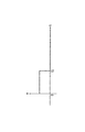
図1は、本発明の液体吐出ヘッドの一実施形態の基本的な構造を説明するための、液流路方向に沿った断面図である。
【0047】
図1に示すように、この液体吐出ヘッドは、液体に気泡を発生させるための熱エネルギーを与える複数個(図1では1つのみ示す)の発熱体2が並列に設けられた素子基板1と、この素子基板1上に接合された天板3と、素子基板1および天板3の前端面に接合されたオリフィスプレート4とを有する。
【0048】
素子基板1は、シリコン等の基体上に絶縁および蓄熱を目的とした酸化シリコン膜または窒化シリコン膜を成膜し、その上に、発熱体2を構成する電気抵抗層および配線電極をパターニングしたものである。この配線電極から電気抵抗層に電圧を印加し、電気抵抗層に電流を流すことで発熱体2が発熱する。
【0049】
天板3は、各発熱体2に対応した複数の液流路7および各液流路7に液体を供給するための共通液室8を構成するためのもので、天井部分から各発熱体2の間に延びる流路側壁9が一体的に設けられている。天板3はシリコン系の材料で構成され、液流路7および共通液室9のパターンをエッチングで形成したり、シリコン基板上にCVD等の公知の成膜方法により窒化シリコン、酸化シリコン等の流路側壁9となる材料を推積した後、液流路7の部分をエッチングして形成することができる。
【0050】
オリフィスプレート4には、各液流路7に対応しそれぞれ液流路7を介して共通液室8に連通する複数の吐出口5が形成されている。オリフィスプレート4もシリコン系の材料からなるものであり、例えば、吐出口5を形成したシリコン基板を10〜150μm程度の厚さに削ることにより形成される。なお、オリフィスプレート4は本発明には必ずしも必要な構成ではなく、オリフィスプレート4を設ける代わりに、天板3に液流路7を形成する際に天板3の先端面にオリフィスプレート4の厚さ相当の壁を残し、この部分に吐出口5を形成することで、吐出口付きの天板とすることもできる。
【0051】
さらに、この液体吐出ヘッドには、発熱体2に対面して配置され、素子基板1に直接固定された片持梁状の可動部材6が設けられている。この可動部材6は屈曲部を有し、この屈曲部により可動部材6の可動部分が基板に対して所定の間隙を有するようになっている。可動部材6をこのような形状とすることによって、可動部材6の固定を強固に行うことができるとともに、間隙を形成するために台座を用いることがなくなるため、従来台座が占めていた空間をも液室の一部とすることができ液室の容積の確保を容易に行うことができる。
【0052】
また、可動部材6を上記構成にする場合には、従来の構成よりも可動部材6の強度を必要とするため、本発明では可動部材6を窒化シリコンや酸化シリコン等のシリコン系の材料等で形成された薄膜で構成している。これら材料は従来の可動部材6の材料として用いられているニッケルよりも強度に優れているとともに基板の表面に設けられる無機絶縁保護層15(図2参照)との密着性に優れているため、上記構成において安定した性能を発揮することができる。また、基板1の表面にTaからなるような耐キャビテーション層16(図2参照)が設けられている場合には、基板1の可動部材6との接合部分の耐キャビテーション層16を除去したり、可動部材6の支持固定部と基板1との間に密着層23(図8参照)を設けることによって、可動部材6と基板1との密着性を向上させることができる。さらに、上記材料は、水素イオン指数(pH)の高い液体に対する耐食性も良好である。
【0053】
また、この可動部材6は、液体の吐出動作によって共通液室8から可動部材6の上方を経て吐出口5側ヘ流れる大きな流れの上流側において素子基板1に支持固定され、可動部分の屈曲部近傍に支点6aが構成されている。さらに、この支点6aに対して下流側に自由端6bを持つように、発熱体2に面した位置に発熱体2の少なくとも一部を覆うような状態で発熱体2から所定の距離を隔てて配されている。ここで、本発明の可動部材6は、屈曲部を有していることから支点部分にかかる負荷が従来の形状よりも大きくなるため、可動部材6の耐久性をより向上させる目的で支点6a部分に曲面部を有する構成としている。また、この発熱体2と可動部材6との間が気泡発生領域10となる。なお、基板1と可動部材6との間隙は1〜20μmが好ましく、より好ましくは1〜10μmである。このようにすることにより、可動部材6によって気泡のエネルギーをより効率的に制御することができるとともに、可動部材6の動作安定性を向上させることができる。また、可動部材5の厚みとしては5μm程度までに抑えることにより、可動部材6の動作追従性を増すことができる。
【0054】
上記構成に基づき、発熱体2を発熱させると、可動部材6と発熱体2との間の気泡発生領域10の液体に熱が作用し、これにより発熱体2上に膜沸騰現象に基づく気泡が発生し、成長する。この気泡の成長に伴う圧力は可動部材6に優先的に作用し、可動部材6の自由端6bは図1に破線で示されるように、支点6aを中心に吐出口5側(定常状態における前記可動部材と、流路の基板に対面する面との間に設けられた間隙)に大きく開くように変位する。可動部材6の変位もしくは変位した状態によって、気泡の発生に基づく圧力の伝搬や気泡自身の成長が吐出口5側に導かれ、吐出口5から液体が吐出する。
【0055】
つまり、気泡発生領域10上に、液流路7内の液体の流れの上流側(共通液室8側)に支点6aを持ち下流側(吐出口5側)に自由端6bを持つ可動部材6を設けることによって、気泡の圧力伝搬方向が下流側ヘ導かれ、気泡の圧力が直接的に効率よく吐出に寄与することになる。そして、気泡の成長方向自体も圧力伝搬方向と同様に下流方向に導かれ、上流より下流で大きく成長する。このように、気泡の成長方向自体を可動部材によって制御し、気泡の圧力伝搬方向を制御することで、吐出効率や吐出力または吐出速度等の根本的な吐出特性を向上させることができる。
【0056】
一方、気泡が消泡工程に入ると、可動部材6の弾性力との相乗効果で気泡は急速に消泡し、可動部材6も最終的には図1に実線で示した初期位置に復帰する。このとき、気泡発生領域10での気泡の収縮体積を補うため、また、吐出された液体の体積分を補うために、上流側すなわち共通液室8側から液体が流れ込み、液流路7ヘの液体の充填(リフィル)が行われるが、この液体のリフィルは、可動部材6の復帰作用に伴って効率よく合理的かつ安定して行われる。
【0057】
上記説明したように、本実施形態の可動部材6は支点6aの部分に曲面部を有しているので、可動部材6が図1に破線で示すように開いたときに支点6aにかかる負荷が分散される。そのため、可動部材6の機械的な耐久性が増し、ひいては液体吐出ヘッドの信頼性が向上される。
【0058】
ここで、図1に示した液体吐出ヘッドにおける素子基板の詳細な構成について、図2を参照して説明する。
【0059】
図2は図1に示した液体吐出ヘッドの断面図であり、図2(a)は後述する保護膜がある液体吐出ヘッドを示す図、図2(b)は保護膜がない液体吐出ヘッドを示す図である。
【0060】
図2に示すように、素子基板1上には可動部材6が設けられており、天板3と可動部材6との間には液流路7が構成されている。
【0061】
素子基板1は、シリコン等からなる基体11上に、絶縁および蓄熱を目的とした酸化シリコンまたは窒化シリコンからなるシリコン膜12が成膜されており、その上に0.01〜0.2μm厚の発熱体を構成するハフニュウムボライド(HfB2)、窒化タンタル(TaN)、タンタルアルミ(TaAl)等からなる電気抵抗層13と、0.2〜1.0μm厚のアルミニウム等からなる配線電極14とがパターニングされている。発熱体2は、配線電極14から電気抵抗層13に電圧を印加し、電気抵抗層13に電流を流すことにより発熱される。配線電極14間の電気抵抗層13(すなわち発熱体2)の上には、酸化シリコンや窒化シリコン等からなる無機絶縁保護層15が0.1〜0.2μm厚で形成され、さらにその上に、0.1〜0.6μm厚のタンタル等からなる耐キャビテーション層16が成膜されており、インク等各種の液体から電気抵抗層13を保護している。
【0062】
特に、気泡の発生、消泡の際に発生する圧力や衝撃波は非常に強く、堅くてもろい酸化膜の耐久性を著しく低下させるため、耐キャビテーション層16の材料としては金属材料のタンタル(Ta)等が用いられる。
【0063】
また、液体、液流路構成、抵抗材料の組み合わせによっては上述の保護層15を必要としない構成でもよく、その例を図2(b)に示す。
【0064】
このような保護層を必要としない抵抗層の材料としては、イリジュウム=タンタル=アルミ合金等が挙げられる。特に、発泡に用いられる気泡発生領域10における液体を、液流路7の吐出液と分離して発泡に適したものとする場合には、このように保護層がない場合であっても何ら支障がない。
【0065】
このように、上述した実施の形態における発熱体2の構成としては、配線電極14間の電気抵抗層13(発熱部)だけでもよく、また電気抵抗層13を保護する保護層を含むものでもよい。
【0066】
本実施形態においては、発熱体2として、電気信号に応じて発熱する抵抗層で構成された発熱部を有するものを用いたが、本発明は、これに限られることなく、吐出液を吐出させるのに十分な気泡を気泡発生領域の発泡液に生じさせるものであればよい。例えば、発熱部としてレーザ等の光を受けることで発熱するような光熱変換体や、高周波を受けることで発熱するような発熱部を有する発熱体でもよい。
【0067】
なお、前述の素子基板1には、発熱部を構成する電気抵抗層13と、この電気抵抗層13に電気信号を供給するための配線電極14とで構成される電気熱変換体の他に、この電気熱変換素子を選択的に駆動するためのトランジスタ、ダイオード、ラッチ、シフトレジスタ等の機能素子が一体的に半導体製造工程によって作り込まれていてもよい。
【0068】
また、上述したような素子基板1に設けられている電気熱変換体の発熱部を駆動し、液体を吐出するためには、電気抵抗層13に配線電極14を介して矩形パルスを印加し、配線電極14間の電気抵抗層13を急峻に発熱させればよい。
【0069】
図3は、図2に示した電気抵抗層に印加する電圧波形を示す図である。
【0070】
上述した実施形態における液体吐出装置においては、それぞれ電圧24V、パルス幅7μsec、電流150mA、電気信号を6kHzで加えることで発熱体を駆動させ、前述のような動作によって、吐出口から液体であるインクを吐出させた。しかしながら、本発明における駆動信号の条件はこれに限られることなく、液体を適正に発泡させることができる駆動信号であればよい。
【0071】
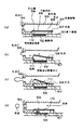
次に、本実施形態の液体吐出ヘッドの特徴である可動部材の製造方法について、図4を参照して詳しく説明する。図4は、図1等に示した液体吐出ヘッドにおける可動部材の製造方法を示す断面図である。
【0072】
まず、図4(a)に示すように、素子基板1上にCVD法などによりBPSG(Boron−doped Phospho−Silicate Glass)膜17を形成する。このBPSG膜17は、可動部材と素子基板1との間に間隙(ギャップ)を形成するための間隙形成部材として機能し、その膜厚は、最終的に可動部材6と発熱体とのギャップに相当する。従って、BPSG膜17の膜厚は、1〜20μmの間で、可動部材による液体吐出効果が液流路全体のバランス上、最も顕著となる値に形成する。
【0073】
次に、BPSG膜17をパターニングするためのレジスト18をスピンコートなどにより塗布し(図4(b)参照)、露光・現像する(図4(c)参照)。これにより、可動部材の支点部分に相当する部分のレジスト18を除去する。ただし、レジスト18の塗布時において、BPSG膜17とレジスト18との密着性を、素子基板1とBPSG膜17との密着性よりも意図的に弱くしておく。
【0074】
これをバッファードフッ酸によるウェットエッチング、あるいはドライエッチング等を行って、レジスト18で覆われていない部分のBPSG膜17を除去する。この時、BPSG膜17とレジスト18との密着性が弱められているためにBPSG膜17の端部では、BPSG膜17とレジスト18との接合面でのエッチング進行速度の方が、BPSG膜17と素子基板1との接合面のそれよりも速くなるため、サイドエッチが進み、結果としてBPSG膜17は図4(d)に示すように端部に凹型曲面状の斜面を持った形状になる。
【0075】
次に、酸素プラズマによるプラズマアッシング、あるいはレジスト除去剤に浸すことにより、残りのレジスト18を除去する(図4(e)参照)。BPSG膜17の上に、可動部材を形成する可動部材用基材部であるSiN膜(窒化シリコン膜)19をプラズマCVD法等によって成膜(図4(f)参照)し、パターニングする(図4(g)参照)。
【0076】
最後に、バッファードフッ酸によるウェットエッチングを行って、SiN膜19の下部に残っているBPSG膜17を全て取り除くと、図4(h)に示すように支点部分の外側に曲面部を有する可動部材6を形成することができる。
【0077】
また、本実施形態では可動部材の材料が窒化シリコンである場合について説明したが、成膜の材料ガスを変えて炭化シリコン、あるいは酸化シリコンを用いても同様に可動部材を形成することができる。このように、シリコン系の材料で可動部材6を形成することにより、液体吐出ヘッドの他の構成がシリコン等の半導体材料で形成されている場合には、液体吐出ヘッド全体を半導体プロセスで形成することが可能となるので、液体吐出ヘッドの製造工程を大幅に簡略化することができる。さらにめっきで可動部材を形成する場合には、したびき層(導電層)が必要であるため可動部材を単層で薄く形成することが難しかったが、本実施形態によれば容易に形成することができる。
【0078】
(液体吐出ヘッドの可動部材の製造方法に係る第2の実施形態)
図4(e)に示したように、サイドエッチングが行われたBPSG膜17のエッジ部の形状は2次曲線状となっており、可動部材6の素子基板1との固定部には滑らかな曲線が得られるものの、支点側には角が残る。そのため、完成される可動部材は支点部分にいまだ角部を有することとなるので、可動部材の機械的耐久性の向上という目的に対してさらに向上させることができる。
【0079】
そこで、本実施形態における液体吐出ヘッドの可動部材の製造方法では、可動部材の支点部分の内側も滑らかな曲面に形成することを目的としている。
【0080】
図5は、図1等に示した液体吐出ヘッドの可動部材の製造方法に係る第2の実施形態を示す断面図である。ここで、図5(a)〜(e)に示す可動部材の製造工程は図4(a)〜(e)を参照して説明した製造工程と同様であるので、詳細な説明は省略する。
【0081】
本実施形態では、図5(e)に示す状態のBPSG膜17に熱処理を加えることで、BPSG膜17の表面と曲面状の斜面との境界に形成される角部を滑らかにする(図5(f)参照)。続いて、BPSG膜17の上に可動部材となるSiN膜(窒化シリコン膜)19を成膜し(図5(g)参照)、パターニングを行う(図5(h)参照)。最後に、BPSG膜17を除去すると、図5(i)に示すように、素子基板1との固定部および支点6a部分に滑らかな曲面部を持つ可動部材6を形成することができる。
【0082】
上記の製造方法によれば、可動部材6の支点6aがより滑らかな曲面形状となるので、可動部材6の支点6aにかかる負荷がさらに分散されるため、可動部材6の機械的な耐久性が一層向上される。
【0083】
また、本実施例では可動部材の間隙形成部材としてBPSGを用いたが、前記の角部を滑らかにするための熱処理を低温で行うために、BPSGの代わりに水ガラス等の低温で変形しやすい材料を用いても良い。または、BPSGを熱処理する代わりに、ドライあるいはウェットでのソフトエッチングを行って角部を滑らかにすることもできる。
【0084】
ソフトエッチングを行う場合には、レジスト18の材料としてBPSGとの選択比(エッチングレート)が約1:1の材料を用い、レジスト18の厚さをBPSG膜17の膜厚とほぼ同等とする。これにより、BPSG膜17が膜厚方向にエッチングされるのと同時に、レジスト18およびBPSG膜17がサイドエッチされるので、BPSG膜17の端部が滑らかな曲面状になる。
【0085】
(液体吐出ヘッドの可動部材の製造方法に係る第3の実施形態)
図6は、図1等に示した液体吐出ヘッドの可動部材の製造方法に係る第3の実施形態を示す断面図である。
【0086】
本実施形態では、まず、素子基板1上に高耐熱性レジスト20をスピンコートなどにより塗布する(図6(a)参照)。次に、高耐熱性レジスト20を露光・現像して、可動部材の固定部に相当する部分の高耐熱性レジスト20を除去する。この高耐熱性レジスト20を露光・現像したときの特徴として、高耐熱性レジスト20の端部の形状は図6(b)に示すように、凸型曲面状の斜面を持った滑らかな形状となる。従って、素子基板1および高耐熱性レジスト20の上に可動部材となるSiN膜(窒化シリコン膜)19をCVDによる低温成膜などの方法によって成膜し(図6(c)参照)、パターニングを行った後(図6(d)参照)、ウェット処理により高耐熱性レジスト20を除去すると、図6(e)に示すように、支点6a部分に滑らかな曲面部が形成された可動部材6を形成することができる。
【0087】
なお、高耐熱性レジスト20は、SiN膜19を成膜する際に変形、変質しないことが必要である。例えば、SiN膜19の成膜が350℃程度で行われる場合、高耐熱性レジスト20は400℃程度の耐熱性を有する必要がある。この場合、高耐熱性レジスト20の材料には、例えばポリイミド系の材料を用いることが好ましい。
【0088】
(液体吐出ヘッドの可動部材の製造方法に係る第4の実施形態)
図7は、図1等に示した液体吐出ヘッドの可動部材の製造方法に係る第4の実施形態を示す断面図である。
【0089】
本実施形態は、素子基板と可動部材の間隙形成部材をメッキによって形成していることを特徴としている。
【0090】
まず、素子基板1上に間隙形成部材をメッキ成形するための電極21を成膜し、パターニングを行う(図7(a)参照)。次に、電極21の周囲にニッケル等からなる金属を成長させ、メッキ22を形成する。メッキ22の場合、膜成長の方向が等方性であるので、図7(b)に示すように、電極21の端部におけるメッキ22は曲面部を持った滑らかな形状となる。
【0091】
続いて、メッキ22および素子基板1の上に可動部材となるSiN膜(窒化シリコン膜)19を成膜し(図7(c)参照)、パターニングを行う(図7(d)参照)。最後に、ウェット処理によってメッキ22および電極21を取り除くと、図7(e)に示すように、支点6aの部分に曲面部を持った可動部材6を形成することが出来る。
【0092】
(液体吐出ヘッドの可動部材の製造方法に係る第5の実施形態)
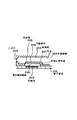
図8は、図1等に示した液体吐出ヘッドの可動部材の製造方法に係る第5の実施形態を示す断面図である。
【0093】
本実施形態は、素子基板上の可動部材が固定される部分に密着層23を設けたことを特徴としている。
【0094】
まず、素子基板1上の可動部材6が固定される部分に、五酸化タンタル(Ta2O5)等からなる、可動部材を構成するSiN膜の応力を緩和し、密着性を高める効果がある密着層23をパターニングする(図8(a)参照)。その後、素子基板1および密着層23上に、ギャップ形成部材である高耐熱性レジスト20を成膜し、パターニングを行う(図8(b)参照)。次に、高耐熱性レジスト20を露光・現像して、可動部材の固定部に相当する部分の高耐熱性レジスト20を除去する(図8(c)参照)。
【0095】
続いて、密着層23および高耐熱性レジスト20の上に、可動部材となるSiN膜(窒化シリコン膜)19をCVDによる低温成膜などの方法によって成膜し(図8(d)参照)、パターニングを行った後(図8(e)参照)、ウェット処理により高耐熱性レジスト20を除去すると、図8(f)に示すように、支点6a部分に滑らかな曲面部が形成された可動部材6を密着層23の上に形成することができる。
【0096】
上記のように、素子基板1上の可動部材6が固定される部分に密着層23を設けることにより、可動部材6の支持固定部と素子基板1との接続強度が増し、可動部材6の機械的な耐久性が一層向上される。なお、第1、第2、第3および第4の実施形態に対しても、本実施形態に説明した密着層23を付加することによって、同様の効果を得られることは明らかである。
【0097】
次に、上記説明した液体吐出ヘッドが搭載された液体吐出ヘッドカートリッジを概略説明する。
【0098】
図9は、前述した液体吐出ヘッドが搭載された液体吐出ヘッドカートリッジの模式的分解斜視図である。図9に示すように、液体吐出ヘッドカートリッジは、主に液体吐出ヘッド部30と液体容器31とから概略構成されている。
【0099】
液体吐出ヘッド部30は、可動部材6(図1等参照)が設けられた素子基板1、天板3およびオリフィスプレート4(共に図1参照)を有する溝付き部材32、押さえばね33、液体供給部材34、支持体(アルミベースプレート)35等からなっている。素子基板1には、前述のように発泡液に熱を与えるための発熱体2(図1等参照)が、複数個、列状に設けられており、また、この発熱体2を選択的に駆動するための機能素子(不図示)が複数設けられている。素子基板1と可動部材6との間には、前述したように気泡発生領域10(図1等参照)が形成されている。この素子基板1と溝付き部材32との接合によって、吐出される吐出液体が流通する液流路7および共通液室8(共に図1参照)が形成される。
【0100】
押さえばね33は、溝付き部材32に素子基板1方向ヘの付勢力を作用させる部材であり、この付勢力により素子基板1、溝付き部材32および後述する支持体35とを良好に一体化させている。
【0101】
支持体35は、素子基板1等を支持するためのものであり、この支持体35上には、素子基板1に接続し電気信号を供給するためのプリント配線基板36や、装置側と接続することで装置側と電気信号のやりとりを行うためのコンタクトパッド37がさらに配置されている。
【0102】
液体容器31は、液体吐出ヘッド部30に供給されるインク等の吐出液体を内部に収容している。液体容器31の外側には、液体吐出ヘッド部30と液体容器31との接続を行う接続部材を配置するための位置決め部38と、接続部材を固定するための固定軸39とが設けられている。吐出液体の供給は、液体容器31の吐出液体供給路40から液体供給部材34の供給路42を介して、各部材の供給路41,43,44を介して共通液室8(図1参照)に供給される。
【0103】
なお、この液体容器31には、液体の消費後に液体を再充填して使用してもよい。このためには液体容器31に液体注入口を設けておくことが望ましい。また、液体吐出ヘッド部30と液体容器31とは一体であってもよく、分離可能としてもよい。
【0104】
次に、上記説明した液体吐出ヘッドが搭載された液体吐出装置を、図10を参照して概略説明する。図10は、前述の液体吐出ヘッドが搭載された液体吐出装置の概略構成を示す斜視図である。
【0105】
本実施の形態では、特に吐出液体としてインクを用いたインク吐出記録装置IJRAを用いて説明する。液体吐出装置のキャリッジHCは、インクを収容する液体容器31と液体吐出ヘッド部30とが着脱可能なへッドカートリッジを搭載しており、被記録媒体搬送手段で搬送される記録紙等の被記録媒体50の幅方向(矢印a,b方向)に往復移動する。
【0106】
本実施形態の液体吐出装置では、不図示の駆動信号供給手段からキャリッジHC上の液体吐出手段に駆動信号が供給されると、この信号に応じて液体吐出ヘッド部30から被記録媒体50に対して記録液体が吐出される。
【0107】
また、本実施形態の液体吐出装置においては、被記録媒体搬送手段とキャリッジHCを駆動するための駆動源としてのモータ51、駆動源からの動力をキャリッジHCに伝えるためのギア52,53、及びキャリッジ軸54等を有している。この記録装置及びこの記録装置で行う液体吐出によって、各種の被記録媒体に対して良好な画像の記録物を得ることができる。
【0108】
図11は、前述の液体吐出ヘッドが適用されたインク吐出記録装置を動作させるための装置全体のブロック図である。
【0109】
記録装置は、ホストコンピュータ60より印字情報を制御信号として受ける。印字情報は記録装置内部の入出力インタフェイス61に一時保存されると同時に、記録装置内で処理可能なデータに変換され、ヘッド駆動信号供給手段を兼ねるCPU62に入力される。CPU62はROM63に保存されている制御プログラムに基づき、前記CPU62に入力されたデータをRAM64等の周辺ユニットを用いて処理し、印字するデータ(画像データ)に変換する。
【0110】
またCPU62は前記画像データを被記録媒体上の適当な位置に記録するために、画像データに同期して被記録媒体50およびキャリッジHC(共に図10参照)を移動する駆動用モータ51を駆動するための駆動データを作る。画像データおよびモータ駆動データは、各々ヘッドドライバ66と、モータドライバ65を介し、キャリッジHCおよび駆動モータ51に伝達され、それぞれ制御されたタイミングで駆動され画像を形成する。
【0111】
上述のような記録装置に適用でき、インク等の液体の付与が行われる被記録媒体としては、各種の紙やOHPシート、コンパクトディスクや装飾板等に用いられるプラスチック材、布帛、アルミニウムや銅等の金属材、牛皮、豚皮、人工皮革等の皮革材、木、合板等の木材、竹材、タイル等のセラミックス材、スポンジ等の三次元構造体等を対象とすることができる。
【0112】
また、上述の記録装置として、各種の紙やOHPシート等に対して記録を行うプリンタ装置、コンパクトディスク等のプラスチック材に記録を行うプラスチック用記録装置、金属板に記録を行う金属用記録装置、皮革に記録を行う皮革用記録装置、木材に記録を行う木材用記録装置、セラミックス材に記録を行うセラミックス用記録装置、スポンジ等の三次元網状構造体に対して記録を行う記録装置、又布帛に記録を行う捺染装置等をも含むものである。
【0113】
また、これらの液体吐出装置に用いられる吐出液は、夫々の被記録媒体や記録条件に合わせた液体であることが好ましい。
【0114】
【発明の効果】
以上説明したように、本発明は、前記可動部材の支点部が曲面形状に形成されているので、可動部材が支点部を中心として吐出口側に変位されたときに支点部にかかる負荷が分散されるため、可動部材の機械的な耐久性を向上させることができ、ひいては液体吐出ヘッドの信頼性を向上させることができる。
【図面の簡単な説明】
【図1】本発明の液体吐出ヘッドの一実施形態の基本的な構造を説明するための、液流路方向に沿った断面図である。
【図2】図1に示した液体吐出ヘッドの断面図である。
【図3】図2に示した電気抵抗層に印加する電圧波形を示す図である。
【図4】図1等に示した液体吐出ヘッドにおける可動部材の製造方法を示す断面図である。
【図5】図1等に示した液体吐出ヘッドの可動部材の製造方法に係る第2の実施形態を示す断面図である。
【図6】図1等に示した液体吐出ヘッドの可動部材の製造方法に係る第3の実施形態を示す断面図である。
【図7】図1等に示した液体吐出ヘッドの可動部材の製造方法に係る第4の実施形態を示す断面図である。
【図8】図1等に示した液体吐出ヘッドの可動部材の製造方法に係る第5の実施形態を示す断面図である。
【図9】本発明の液体吐出ヘッドが搭載された液体吐出ヘッドカートリッジの模式的分解斜視図である。
【図10】本発明の液体吐出ヘッドが搭載された液体吐出装置の概略構成を示す斜視図である。
【図11】本発明の液体吐出ヘッドが適用されたインク吐出記録装置を動作させるための装置全体のブロック図である。
【図12】従来の液体吐出ヘッドにおける吐出原理を説明するための図である。
【図13】図12に示した液体吐出ヘッドの部分破断斜視図である。
【図14】従来の液体吐出ヘッドの他の例を示す断面図である。
【符号の説明】
1 素子基板
2 発熱体
3 天板
4 オリフィスプレート
5 吐出口
6 可動部材
6a 支点
6b 自由端
7 液流路
8 共通液室
9 流路側壁
10 気泡発生領域
11 基体
12 シリコン膜
13 電気抵抗層
14 配線電極
15 保護層
16 耐キャビテーション層
17 BPSG膜
18 レジスト
19 SiN膜
20 高耐熱性レジスト
21 電極
22 メッキ
23 密着層
30 液体吐出ヘッド部
31 液体容器
32 溝付き部材
33 押さえばね
34 液体供給部材
35 支持体
36 プリント配線基板
37 コンタクトパッド
38 位置決め部
39 固定軸
40 吐出液体供給路
41,43,44 供給路
50 被記録媒体
51 モータ
52,53 ギア
54 キャリッジ軸
60 ホストコンピュータ
61 入出力インターフェイス
62 CPU
63 ROM
64 RAM
65 モータドライバ
66 ヘッドドライバ[0001]
BACKGROUND OF THE INVENTION
The present invention relates to a liquid discharge head that discharges a desired liquid by generating bubbles generated by applying thermal energy to the liquid. Manufacturing method About. In particular, a liquid ejection head having a movable member that is displaced by utilizing the generation of bubbles. Manufacturing method About.
[0002]
In the present invention, “recording” means not only giving an image having a meaning such as a character or a figure to a recording medium but also giving an image having no meaning such as a pattern. To do.
[0003]
[Prior art]
By applying energy such as heat to the ink, the ink undergoes a change in state accompanied by a steep volume change (bubble generation), and the ink is discharged from the discharge port by the action force based on this change in state, and this is recorded 2. Description of the Related Art An ink jet recording method for forming an image by adhering to a medium, a so-called bubble jet recording method has been conventionally known. In a recording apparatus using this bubble jet recording method, as disclosed in JP-B-61-59911 and JP-B-61-59914, an ejection port for ejecting ink and a communication with the ejection port are provided. In general, an ink flow path and a heating element (electrothermal converter) as an energy generating means for discharging ink disposed in the ink flow path are provided.
[0004]
According to the recording method as described above, a high-quality image can be recorded at high speed and with low noise, and in the head for performing this recording method, the ejection ports for ejecting ink can be arranged at high density. Therefore, it has many excellent points such that a high-resolution recorded image and a color image can be easily obtained with a small apparatus. For this reason, in recent years, this bubble jet recording method has been used in many office devices such as printers, copiers, and facsimiles, and has also been used in industrial systems such as textile printing apparatuses.
[0005]
Therefore, some of the inventors returned to the principle of liquid ejection, and conducted intensive research to provide a novel liquid ejection method using bubbles that could not be obtained in the past and a head used therefor, Japanese Patent Application Laid-Open No. 9-201966 has been filed.
[0006]
Here, a conventional liquid discharge method disclosed in Japanese Patent Laid-Open No. 9-201966 and the like and a head used therefor will be described with reference to FIG. FIG. 12 is a diagram for explaining the ejection principle in the conventional liquid ejection head, and is a cross-sectional view in the liquid flow path direction. FIG. 13 is a partially broken perspective view of the liquid discharge head shown in FIG. The liquid discharge head shown in FIG. 12 and the like has the most basic configuration that improves the discharge force and discharge efficiency by controlling the propagation direction of pressure based on bubbles and the growth direction of bubbles when discharging liquid. .
[0007]
The terms “upstream” and “downstream” used in the following description refer to the flow direction of the liquid from the liquid supply source to the discharge port through the bubble generation region (or the movable member) or on this configuration. Expressed as a representation of direction.
[0008]
The “downstream side” with respect to the bubble itself represents a portion of the bubble outlet side which is supposed to act directly on the droplet discharge. More specifically, it means a bubble generated in a region downstream of the center of the bubble with respect to the flow direction or the structural direction, or in a region on the heating element downstream of the area center.
[0009]
Further, “comb teeth” means a shape in which the fulcrum portion of the movable member is a common member and the front of the free end is open.
[0010]
In the example shown in FIG. 12, the liquid ejection head includes a heating element 102 (in this example, a heating resistor having a shape of 40 μm × 105 μm) that applies thermal energy to the liquid as an ejection energy generating element for ejecting the liquid. Provided on the
[0011]
On the
[0012]
Further, by making the
[0013]
The
[0014]
Heat is applied to the liquid in the
[0015]
As described above, the technique disclosed in Japanese Patent Laid-Open No. 9-201966, etc., shows the positional relationship between the fulcrum of the movable member in the liquid passage and the free end, and the relationship in which the free end is positioned on the discharge port side, that is, on the downstream side. In addition, the movable member is disposed so as to face the heating element or the bubble generation region, thereby actively controlling the bubbles.
[0016]
Further, as described above, by providing a pedestal in the fixed part of the movable member, a gap of about 1 to 20 μm is formed between the movable member and the heating element, and the effect of improving the liquid discharge efficiency by the movable member is achieved. Pulled out enough. Therefore, according to the liquid discharge head or the like based on the extremely novel discharge principle as described above, a synergistic effect between the generated bubbles and the movable member displaced thereby can be obtained, and the liquid near the discharge port can be discharged efficiently. Therefore, the liquid ejection efficiency is improved as compared with the conventional bubble jet type ejection method, head, and the like.
[0017]
Various materials can be considered for the movable member used in the above-described liquid discharge head. Nickel having excellent elasticity is generally used in order to efficiently use the pressure caused by the generation of bubbles for liquid discharge. It is used for.
[0018]
[Problems to be solved by the invention]
However, if the pedestal is provided at the fixed portion of the movable member in the liquid ejection head, there is a problem that the forming process of the movable member becomes complicated. In addition, if the movable member is to be firmly fixed with such a configuration, it is necessary to secure a certain length of the base portion in the ink flow direction. Since the pedestal occupies the portion, there is a possibility that the ink supply characteristics cannot be sufficiently exhibited especially when it is desired to miniaturize the head or when the flow paths are arranged with high density.
[0019]
The present invention has been made in view of the above-described problems, and can improve ink supply characteristics and reliability, and can simplify a manufacturing process. Manufacturing method Is intended to provide.
[0020]
[Means for Solving the Problems]
In order to achieve the above object, a method for manufacturing a liquid discharge head according to the present invention includes: a discharge port for discharging a liquid; and a liquid flow path connected to the discharge port for supplying the liquid to the discharge port. The substrate provided with a heating element for generating bubbles in the liquid filled in the liquid flow path, and the pressure generated by generating the bubbles with the discharge port side as a free end, Displaceable around a fulcrum located upstream of the free end in the flow direction of the liquid in the flow path A cantilever-shaped movable member, which is disposed at a position facing the heating element of the substrate with a gap between the substrate and an upstream portion of the fulcrum portion in the liquid flow direction Supported and fixed to the substrate A liquid discharge head manufacturing method comprising: a step of forming a gap forming member for forming the gap on the substrate; and the movable member on the substrate and the gap forming member. Forming a movable member base layer made of a silicon-based material forming the member, patterning the movable member base layer to form the movable member, and removing the gap forming member Before the step of forming the movable member base layer forming the movable member on the substrate and the gap forming member, a fulcrum portion of the movable member is formed on the gap forming member. A step of forming the portion to be curved into a curved shape.
[0032]
Thereby, when the movable member is displaced to the discharge port side around the fulcrum portion, the load applied to the fulcrum portion is dispersed, so that a liquid discharge head that improves the mechanical durability of the movable member is manufactured. The
[0033]
The step of forming a portion of the gap forming member that forms the fulcrum portion of the movable member into a curved shape includes forming a resist for patterning the gap forming member on the gap forming member; It is preferable to include a step of removing a portion of the gap forming member not covered with the resist by etching.
[0034]
Further, by setting the adhesiveness between the gap forming member and the resist to be weaker than the adhesiveness between the gap forming member and the substrate, the etching progress rate at the joint surface between the gap forming member and the resist is increased. However, since it is faster than that of the joint surface between the gap forming member and the substrate, a concave curved slope is formed at the end of the gap forming member.
[0035]
Further, by using a material that has an etching selection ratio of about 1: 1 with the gap forming member as the resist material, the resist and the gap are simultaneously etched in the thickness direction. Since the gap forming member is side-etched, the end of the gap forming member becomes a smooth curved surface.
[0036]
In addition, after the step of forming the portion of the gap forming member that forms the fulcrum portion of the movable member into a curved surface shape, the boundary between the surface of the gap forming member and the portion of the gap forming member that forms the fulcrum portion is formed. By adopting a structure having a step for removing the formed corner portion, the fulcrum portion of the movable member has a smoother curved surface shape, so that the load applied to the fulcrum portion of the movable member is further dispersed, so that the movable member is movable. The mechanical durability of the member is further improved.
[0037]
Further, the step for removing the corner formed at the boundary between the surface of the gap forming member and the portion forming the fulcrum of the movable member is a heat treatment for melting the corner of the gap forming member. It is preferable to have a configuration comprising the steps of performing the above.
[0038]
Further, the material for the gap forming member may be a high heat resistant resist having a feature that a convex curved slope is formed at the end when exposure and development processing are performed.
[0039]
In addition, by using silicon nitride, silicon oxide, or silicon carbide as the material of the movable member, when the other configuration of the liquid discharge head is formed of a semiconductor material such as silicon, the liquid discharge head Since the whole can be formed by a semiconductor process, the manufacturing process of the liquid discharge head is simplified.
[0045]
DETAILED DESCRIPTION OF THE INVENTION
Next, embodiments of the present invention will be described with reference to the drawings.
[0046]
FIG. 1 is a cross-sectional view along the liquid flow path direction for explaining the basic structure of an embodiment of the liquid ejection head of the present invention.
[0047]
As shown in FIG. 1, this liquid ejection head includes an
[0048]
The
[0049]
The
[0050]
In the
[0051]
Further, the liquid ejection head is provided with a cantilevered
[0052]
Further, when the
[0053]
Further, the
[0054]
Based on the above configuration, when the
[0055]
That is, on the
[0056]
On the other hand, when the bubble enters the defoaming step, the bubble rapidly disappears due to a synergistic effect with the elastic force of the
[0057]
As described above, since the
[0058]
Here, a detailed configuration of the element substrate in the liquid discharge head shown in FIG. 1 will be described with reference to FIG.
[0059]
2 is a cross-sectional view of the liquid discharge head shown in FIG. 1, FIG. 2 (a) is a diagram showing a liquid discharge head with a protective film described later, and FIG. 2 (b) is a liquid discharge head without a protective film. FIG.
[0060]
As shown in FIG. 2, a
[0061]
In the
[0062]
In particular, the pressure and shock wave generated when bubbles are generated and defoamed are very strong, and the durability of the hard and brittle oxide film is remarkably lowered. Therefore, the material of the anti-cavitation layer 16 is tantalum (Ta), which is a metal material. Etc. are used.
[0063]
Moreover, the structure which does not require the above-mentioned
[0064]
Examples of the material of the resistance layer that does not require such a protective layer include iridium = tantalum = aluminum alloy. In particular, when the liquid in the
[0065]
As described above, the configuration of the
[0066]
In the present embodiment, the
[0067]
In addition to the electrothermal transducer formed of the
[0068]
Further, in order to drive the heat generating portion of the electrothermal transducer provided on the
[0069]
FIG. 3 is a diagram showing a voltage waveform applied to the electric resistance layer shown in FIG.
[0070]
In the liquid ejection device in the above-described embodiment, the heating element is driven by applying a voltage of 24 V, a pulse width of 7 μsec, a current of 150 mA, and an electrical signal at 6 kHz, and the ink as a liquid is ejected from the ejection port by the operation as described above. Was discharged. However, the condition of the drive signal in the present invention is not limited to this, and any drive signal that can cause the liquid to foam properly can be used.
[0071]
Next, a method for manufacturing the movable member, which is a feature of the liquid discharge head of this embodiment, will be described in detail with reference to FIG. FIG. 4 is a cross-sectional view showing a method for manufacturing a movable member in the liquid ejection head shown in FIG.
[0072]
First, as shown in FIG. 4A, a BPSG (Boron-doped Phospho-Silicate Glass)
[0073]
Next, a resist 18 for patterning the
[0074]
This is subjected to wet etching using buffered hydrofluoric acid, dry etching, or the like to remove the portion of the
[0075]
Next, the remaining resist 18 is removed by plasma ashing using oxygen plasma or immersion in a resist remover (see FIG. 4E). On the
[0076]
Finally, when wet etching using buffered hydrofluoric acid is performed to remove all the
[0077]
Further, although the case where the material of the movable member is silicon nitride has been described in the present embodiment, the movable member can be similarly formed even if silicon carbide or silicon oxide is used by changing the material gas for film formation. Thus, by forming the
[0078]
(Second Embodiment According to Method for Manufacturing Moving Member of Liquid Discharge Head)
As shown in FIG. 4E, the shape of the edge portion of the
[0079]
In view of this, the manufacturing method of the movable member of the liquid ejection head in the present embodiment aims to form a smooth curved surface also inside the fulcrum portion of the movable member.
[0080]
FIG. 5 is a cross-sectional view showing a second embodiment according to the method for manufacturing the movable member of the liquid ejection head shown in FIG. Here, the manufacturing process of the movable member shown in FIGS. 5A to 5E is the same as the manufacturing process described with reference to FIGS. 4A to 4E, and detailed description thereof is omitted.
[0081]
In the present embodiment, the corner portion formed at the boundary between the surface of the
[0082]
According to the above manufacturing method, since the fulcrum 6a of the
[0083]
Further, in this embodiment, BPSG is used as the gap forming member of the movable member. However, in order to perform the heat treatment for smoothing the corners at a low temperature, it is easily deformed at a low temperature such as water glass instead of BPSG. A material may be used. Alternatively, instead of heat-treating BPSG, the corners can be smoothed by dry or wet soft etching.
[0084]
In the case of performing soft etching, a material having a selection ratio (etching rate) with BPSG of about 1: 1 is used as the material of the resist 18, and the thickness of the resist 18 is made substantially equal to the film thickness of the
[0085]
(Third embodiment according to a method of manufacturing a movable member of a liquid discharge head)
FIG. 6 is a cross-sectional view showing a third embodiment according to the method of manufacturing the movable member of the liquid ejection head shown in FIG.
[0086]
In the present embodiment, first, a high heat resistant resist 20 is applied on the
[0087]
Note that the high heat resistant resist 20 needs not to be deformed or altered when the
[0088]
(Fourth embodiment according to a method of manufacturing a movable member of a liquid discharge head)
FIG. 7 is a cross-sectional view showing a fourth embodiment according to the method of manufacturing the movable member of the liquid ejection head shown in FIG.
[0089]
This embodiment is characterized in that a gap forming member between the element substrate and the movable member is formed by plating.
[0090]
First, the
[0091]
Subsequently, a SiN film (silicon nitride film) 19 serving as a movable member is formed on the
[0092]
(Fifth embodiment according to manufacturing method of movable member of liquid discharge head)
FIG. 8 is a cross-sectional view showing a fifth embodiment according to the method of manufacturing the movable member of the liquid ejection head shown in FIG.
[0093]
The present embodiment is characterized in that an
[0094]
First, tantalum pentoxide (Ta) is attached to a portion where the
[0095]
Subsequently, a SiN film (silicon nitride film) 19 serving as a movable member is formed on the
[0096]
As described above, by providing the
[0097]
Next, a liquid discharge head cartridge on which the liquid discharge head described above is mounted will be schematically described.
[0098]
FIG. 9 is a schematic exploded perspective view of a liquid discharge head cartridge on which the liquid discharge head described above is mounted. As shown in FIG. 9, the liquid discharge head cartridge is mainly composed of a liquid
[0099]
The liquid
[0100]
The holding
[0101]
The support 35 is for supporting the
[0102]
The liquid container 31 stores therein a discharge liquid such as ink supplied to the liquid
[0103]
The liquid container 31 may be refilled with liquid after consumption. For this purpose, it is desirable to provide a liquid inlet in the liquid container 31. Further, the liquid
[0104]
Next, a liquid ejection apparatus equipped with the above-described liquid ejection head will be schematically described with reference to FIG. FIG. 10 is a perspective view illustrating a schematic configuration of a liquid discharge apparatus on which the above-described liquid discharge head is mounted.
[0105]
In the present embodiment, an explanation will be given using an ink discharge recording apparatus IJRA using ink as the discharge liquid. The carriage HC of the liquid ejecting apparatus is equipped with a head cartridge in which a liquid container 31 for containing ink and a liquid
[0106]
In the liquid ejection apparatus of the present embodiment, when a drive signal is supplied from a drive signal supply unit (not shown) to the liquid ejection unit on the carriage HC, the liquid
[0107]
In the liquid ejection apparatus according to the present embodiment, the
[0108]
FIG. 11 is a block diagram of the entire apparatus for operating the ink discharge recording apparatus to which the liquid discharge head described above is applied.
[0109]
The recording apparatus receives print information from the
[0110]
Further, the
[0111]
The recording medium that can be applied to the recording apparatus as described above and to which liquid such as ink is applied includes various papers, OHP sheets, plastic materials used for compact discs, decorative plates, etc., fabrics, aluminum, copper, etc. Metal materials, leather materials such as cowhide, pig skin, and artificial leather, wood such as wood and plywood, ceramic materials such as bamboo and tiles, and three-dimensional structures such as sponges can be targeted.
[0112]
Further, as the above-mentioned recording apparatus, a printer apparatus that records on various papers and OHP sheets, a plastic recording apparatus that records on a plastic material such as a compact disc, a metal recording apparatus that records on a metal plate, Leather recording device for recording on leather, wood recording device for recording on wood, ceramic recording device for recording on ceramic material, recording device for recording on three-dimensional network structure such as sponge, fabric It also includes a textile printing apparatus that performs recording.
[0113]
Moreover, it is preferable that the discharge liquid used in these liquid discharge apparatuses is a liquid that matches each recording medium and recording conditions.
[0114]
【The invention's effect】
As described above, according to the present invention, since the fulcrum portion of the movable member is formed in a curved surface shape, the load applied to the fulcrum portion is dispersed when the movable member is displaced toward the discharge port with the fulcrum portion as the center. Therefore, the mechanical durability of the movable member can be improved, and as a result, the reliability of the liquid discharge head can be improved.
[Brief description of the drawings]
FIG. 1 is a cross-sectional view along a liquid flow path direction for explaining a basic structure of an embodiment of a liquid discharge head according to the present invention.
FIG. 2 is a cross-sectional view of the liquid discharge head shown in FIG.
FIG. 3 is a diagram showing a voltage waveform applied to the electric resistance layer shown in FIG. 2;
4 is a cross-sectional view illustrating a method of manufacturing a movable member in the liquid ejection head illustrated in FIG. 1 and the like.
FIG. 5 is a cross-sectional view illustrating a second embodiment according to a method for manufacturing a movable member of the liquid ejection head illustrated in FIG. 1 and the like.
6 is a cross-sectional view illustrating a third embodiment according to a method of manufacturing a movable member of the liquid ejection head illustrated in FIG. 1 and the like.
FIG. 7 is a cross-sectional view illustrating a fourth embodiment according to a method for manufacturing a movable member of the liquid ejection head illustrated in FIG. 1 and the like.
FIG. 8 is a cross-sectional view illustrating a fifth embodiment of the method for manufacturing the movable member of the liquid ejection head illustrated in FIG. 1 and the like.
FIG. 9 is a schematic exploded perspective view of a liquid discharge head cartridge on which the liquid discharge head of the present invention is mounted.
FIG. 10 is a perspective view showing a schematic configuration of a liquid discharge apparatus equipped with the liquid discharge head of the present invention.
FIG. 11 is a block diagram of the entire apparatus for operating the ink discharge recording apparatus to which the liquid discharge head of the present invention is applied.
FIG. 12 is a diagram for explaining a discharge principle in a conventional liquid discharge head.
13 is a partially broken perspective view of the liquid discharge head shown in FIG.
FIG. 14 is a cross-sectional view illustrating another example of a conventional liquid discharge head.
[Explanation of symbols]
1 Element substrate
2 Heating element
3 Top plate
4 Orifice plate
5 Discharge port
6 Movable members
6a fulcrum
6b Free end
7 Liquid flow path
8 Common liquid chamber
9 Channel side wall
10 Bubble generation area
11 Substrate
12 Silicon film
13 Electrical resistance layer
14 Wiring electrode
15 Protective layer
16 Anti-cavitation layer
17 BPSG membrane
18 resist
19 SiN film
20 High heat resistance resist
21 electrodes
22 plating
23 Adhesion layer
30 Liquid discharge head
31 Liquid container
32 Grooved member
33 Presser spring
34 Liquid supply member
35 Support
36 Printed circuit board
37 Contact Pad
38 Positioning part
39 Fixed shaft
40 Discharge liquid supply path
41, 43, 44 Supply path
50 Recording medium
51 motor
52, 53 gear
54 Carriage shaft
60 Host computer
61 I / O interface
62 CPU
63 ROM
64 RAM
65 Motor driver
66 Head Driver
Claims (8)
該吐出口に前記液体を供給するために前記吐出口に連通された液流路と、
該液流路に充填された前記液体に気泡を発生させるための発熱体が備えられた基板と、
前記吐出口側を自由端とし、前記気泡が発生されることにより生じる圧力によって、前記液流路における前記液体の流れ方向に関して前記自由端の上流側に位置する支点部を中心に変位可能な片持梁状の可動部材であって、前記基板の前記発熱体に対面する位置に前記基板との間に間隙をおいて配され、かつ前記液体の流れ方向に関して前記支点部の上流側の部分が前記基板に支持固定された可動部材と、を備える液体吐出ヘッドの製造方法であって、
前記基板の上に前記間隙を形成するための間隙形成部材を形成する工程と、
前記基板および前記間隙形成部材の上に、前記可動部材をなすシリコン系の材料からなる可動部材用基材層を成膜する工程と、
前記可動部材用基材層をパターニングして前記可動部材を形成する工程と、
前記間隙形成部材を除去する工程とを有し、
前記基板および前記間隙形成部材の上に、前記可動部材をなす可動部材用基材層を形成する工程の前には、前記間隙形成部材の、前記可動部材の支点部を形成する部分を曲面形状に形成する工程を有することを特徴とする液体吐出ヘッドの製造方法。A discharge port for discharging liquid;
A liquid flow path communicating with the discharge port to supply the liquid to the discharge port;
A substrate provided with a heating element for generating bubbles in the liquid filled in the liquid flow path;
A piece displaceable around a fulcrum located upstream of the free end with respect to the flow direction of the liquid in the liquid flow path due to the pressure generated when the bubbles are generated with the discharge port side as a free end A movable member in the form of a supporting beam, which is disposed at a position facing the heating element of the substrate with a gap between the substrate and an upstream portion of the fulcrum portion with respect to the liquid flow direction. the method of manufacturing a liquid discharge head and a movable member supported fixed to the substrate,
Forming a gap forming member for forming the gap on the substrate;
Forming a movable member base layer made of a silicon-based material forming the movable member on the substrate and the gap forming member;
Patterning the base member layer for the movable member to form the movable member;
Removing the gap forming member,
Before the step of forming the movable member base material layer forming the movable member on the substrate and the gap forming member, the portion of the gap forming member that forms the fulcrum portion of the movable member is curved. A method for manufacturing a liquid discharge head, comprising the steps of:
前記間隙形成部材の前記レジストが覆われていない部分をエッチングにより除去する工程とを有する請求項1に記載の液体吐出ヘッドの製造方法。Forming the portion of the gap forming member forming the fulcrum portion of the movable member into a curved shape includes forming a resist for patterning the gap forming member on the gap forming member;
Method for manufacturing a liquid discharge head according to claim 1 and a step of removing the resist is not covered portion of the gap forming member by etching.
Priority Applications (4)
| Application Number | Priority Date | Filing Date | Title |
|---|---|---|---|
| DE69823461T DE69823461T2 (en) | 1997-12-05 | 1998-12-04 | Liquid ejection head, method of manufacturing the liquid ejection head, cassette with this liquid ejection head and liquid ejection device |
| JP34607498A JP3927711B2 (en) | 1997-12-05 | 1998-12-04 | Method for manufacturing liquid discharge head |
| EP98123169A EP0920996B1 (en) | 1997-12-05 | 1998-12-04 | Liquid discharging head, method of manufacturing the liquid discharging head, head cartridge carrying the liquid discharging head thereon and liquid discharging apparatus |
| US09/206,279 US6196667B1 (en) | 1997-12-05 | 1998-12-07 | Liquid discharging head, method of manufacturing the liquid discharging head, head cartridge carrying the liquid discharging head thereon and liquid discharging apparatus |
Applications Claiming Priority (3)
| Application Number | Priority Date | Filing Date | Title |
|---|---|---|---|
| JP33610597 | 1997-12-05 | ||
| JP9-336105 | 1997-12-05 | ||
| JP34607498A JP3927711B2 (en) | 1997-12-05 | 1998-12-04 | Method for manufacturing liquid discharge head |
Publications (2)
| Publication Number | Publication Date |
|---|---|
| JPH11235827A JPH11235827A (en) | 1999-08-31 |
| JP3927711B2 true JP3927711B2 (en) | 2007-06-13 |
Family
ID=26575359
Family Applications (1)
| Application Number | Title | Priority Date | Filing Date |
|---|---|---|---|
| JP34607498A Expired - Fee Related JP3927711B2 (en) | 1997-12-05 | 1998-12-04 | Method for manufacturing liquid discharge head |
Country Status (4)
| Country | Link |
|---|---|
| US (1) | US6196667B1 (en) |
| EP (1) | EP0920996B1 (en) |
| JP (1) | JP3927711B2 (en) |
| DE (1) | DE69823461T2 (en) |
Families Citing this family (13)
| Publication number | Priority date | Publication date | Assignee | Title |
|---|---|---|---|---|
| US6886915B2 (en) | 1999-10-19 | 2005-05-03 | Silverbrook Research Pty Ltd | Fluid supply mechanism for a printhead |
| US6378993B1 (en) | 1998-12-03 | 2002-04-30 | Canon Kabushiki Kaisha | Liquid discharge head, producing method therefor and liquid discharge apparatus |
| AUPQ130899A0 (en) * | 1999-06-30 | 1999-07-22 | Silverbrook Research Pty Ltd | A method and apparatus (IJ47V12) |
| AUPQ131099A0 (en) * | 1999-06-30 | 1999-07-22 | Silverbrook Research Pty Ltd | A method and apparatus (IJ47V8) |
| AUPQ130399A0 (en) * | 1999-06-30 | 1999-07-22 | Silverbrook Research Pty Ltd | A method and apparatus (IJ47V9) |
| EP1080906A3 (en) | 1999-09-03 | 2002-04-24 | Canon Kabushiki Kaisha | Liquid discharge head, liquid discharge method, and liquid discharge apparatus |
| US6435670B1 (en) | 2000-02-15 | 2002-08-20 | Canon Kabushiki Kaisha | Liquid discharge head, liquid discharge method, liquid discharge apparatus, recovery method for liquid discharge head, and fluid structure body |
| JP3584193B2 (en) | 2000-02-15 | 2004-11-04 | キヤノン株式会社 | Liquid discharge head, liquid discharge device, and method of manufacturing the liquid discharge head |
| US6834423B2 (en) | 2000-07-31 | 2004-12-28 | Canon Kabushiki Kaisha | Method of manufacturing a liquid discharge head |
| JP4095368B2 (en) | 2001-08-10 | 2008-06-04 | キヤノン株式会社 | Method for producing ink jet recording head |
| JP2003311982A (en) * | 2002-04-23 | 2003-11-06 | Canon Inc | Liquid discharge head |
| DE602005022448D1 (en) * | 2004-06-28 | 2010-09-02 | Canon Kk | EKOPFS AND LIQUID HEADER RECEIVED USING THIS METHOD |
| JP4459037B2 (en) * | 2004-12-01 | 2010-04-28 | キヤノン株式会社 | Liquid discharge head |
Family Cites Families (12)
| Publication number | Priority date | Publication date | Assignee | Title |
|---|---|---|---|---|
| CA1127227A (en) | 1977-10-03 | 1982-07-06 | Ichiro Endo | Liquid jet recording process and apparatus therefor |
| US4611219A (en) | 1981-12-29 | 1986-09-09 | Canon Kabushiki Kaisha | Liquid-jetting head |
| JPS6159911A (en) | 1984-08-30 | 1986-03-27 | Nec Corp | Changeover switch circuit |
| JPS6159914A (en) | 1984-08-31 | 1986-03-27 | Fujitsu Ltd | Digital compressor |
| US5479197A (en) | 1991-07-11 | 1995-12-26 | Canon Kabushiki Kaisha | Head for recording apparatus |
| JP3342279B2 (en) | 1995-01-13 | 2002-11-05 | キヤノン株式会社 | Liquid discharge method, liquid discharge head, and method of manufacturing the liquid discharge head |
| AU4092296A (en) * | 1995-01-13 | 1996-08-08 | Canon Kabushiki Kaisha | Liquid ejecting head, liquid ejecting device and liquid ejecting method |
| TW365578B (en) * | 1995-04-14 | 1999-08-01 | Canon Kk | Liquid ejecting head, liquid ejecting device and liquid ejecting method |
| DE69626879T2 (en) * | 1995-04-26 | 2004-02-05 | Canon K.K. | Liquid ejection head, liquid ejection device and liquid ejection method |
| US6154237A (en) * | 1995-12-05 | 2000-11-28 | Canon Kabushiki Kaisha | Liquid ejecting method, liquid ejecting head and liquid ejecting apparatus in which motion of a movable member is controlled |
| US5880752A (en) * | 1996-05-09 | 1999-03-09 | Hewlett-Packard Company | Print system for ink-jet pens |
| JP3542460B2 (en) * | 1996-06-07 | 2004-07-14 | キヤノン株式会社 | Liquid discharge method and liquid discharge device |
-
1998
- 1998-12-04 JP JP34607498A patent/JP3927711B2/en not_active Expired - Fee Related
- 1998-12-04 DE DE69823461T patent/DE69823461T2/en not_active Expired - Fee Related
- 1998-12-04 EP EP98123169A patent/EP0920996B1/en not_active Expired - Lifetime
- 1998-12-07 US US09/206,279 patent/US6196667B1/en not_active Expired - Fee Related
Also Published As
| Publication number | Publication date |
|---|---|
| EP0920996A2 (en) | 1999-06-09 |
| DE69823461D1 (en) | 2004-06-03 |
| JPH11235827A (en) | 1999-08-31 |
| EP0920996B1 (en) | 2004-04-28 |
| EP0920996A3 (en) | 2000-07-05 |
| US6196667B1 (en) | 2001-03-06 |
| DE69823461T2 (en) | 2005-04-14 |
Similar Documents
| Publication | Publication Date | Title |
|---|---|---|
| JP3927711B2 (en) | Method for manufacturing liquid discharge head | |
| JPH11227209A (en) | Liquid jet head, head cartridge and liquid jet unit | |
| JP3697089B2 (en) | Inkjet head substrate, inkjet head, inkjet cartridge, and inkjet recording apparatus | |
| JPH1199649A (en) | Ink jet head, manufacture thereof, and ink jet unit | |
| JP3408060B2 (en) | Liquid discharge method and apparatus and liquid discharge head used for these | |
| JP2001225475A (en) | Liquid ejection head, its manufacturing method, and liquid ejector | |
| JP3548536B2 (en) | Manufacturing method of liquid ejection head | |
| JP3768648B2 (en) | Liquid discharge method, liquid discharge head, and head cartridge and liquid discharge apparatus using the liquid discharge head | |
| JP3907329B2 (en) | Liquid discharge head and liquid discharge apparatus | |
| US20020027577A1 (en) | Liquid discharge head, method for manufacturing liquid discharge head, head cartridge on which liquid discharge head is mounted, and liquid discharge apparatus | |
| US6299293B1 (en) | Substrate for liquid discharge head, liquid discharge head and liquid discharge apparatus | |
| JPH1016243A (en) | Manufacture of liquid emitting head and liquid emitting head obtained by this manufacturing | |
| JP3862524B2 (en) | Liquid discharge head, liquid discharge apparatus, and method of manufacturing liquid discharge head | |
| JP3639707B2 (en) | Liquid discharge head and head substrate | |
| JP3943716B2 (en) | Liquid discharge head and liquid discharge apparatus | |
| JPH1148488A (en) | Liquid jet head and manufacture thereof | |
| JP3535817B2 (en) | Liquid discharge method, liquid discharge head, liquid discharge device | |
| JP2000225705A (en) | Substrate for liquid jet head, liquid jet head and liquid jet device | |
| JP3507421B2 (en) | Liquid discharge head, liquid discharge device, and liquid discharge method | |
| JPH1148500A (en) | Liquid jet head, manufacture thereof and movable member therefor | |
| JPH1148483A (en) | Liquid jet head and manufacture thereof | |
| JP2001287364A (en) | Substrate for ink jet head, ink jet head and ink jet recorder | |
| JPH064330B2 (en) | Inkjet head | |
| JPH1016232A (en) | Liquid emitting head and its production | |
| JP2000006408A (en) | Liquid discharge head and liquid discharge apparatus |
Legal Events
| Date | Code | Title | Description |
|---|---|---|---|
| A977 | Report on retrieval |
Free format text: JAPANESE INTERMEDIATE CODE: A971007 Effective date: 20050523 |
|
| A131 | Notification of reasons for refusal |
Free format text: JAPANESE INTERMEDIATE CODE: A131 Effective date: 20050601 |
|
| A521 | Request for written amendment filed |
Free format text: JAPANESE INTERMEDIATE CODE: A523 Effective date: 20050725 |
|
| A131 | Notification of reasons for refusal |
Free format text: JAPANESE INTERMEDIATE CODE: A131 Effective date: 20060301 |
|
| A521 | Request for written amendment filed |
Free format text: JAPANESE INTERMEDIATE CODE: A523 Effective date: 20060407 |
|
| TRDD | Decision of grant or rejection written | ||
| A01 | Written decision to grant a patent or to grant a registration (utility model) |
Free format text: JAPANESE INTERMEDIATE CODE: A01 Effective date: 20070214 |
|
| A61 | First payment of annual fees (during grant procedure) |
Free format text: JAPANESE INTERMEDIATE CODE: A61 Effective date: 20070305 |
|
| R150 | Certificate of patent or registration of utility model |
Free format text: JAPANESE INTERMEDIATE CODE: R150 |
|
| LAPS | Cancellation because of no payment of annual fees |