JP3927655B2 - camera - Google Patents
camera Download PDFInfo
- Publication number
- JP3927655B2 JP3927655B2 JP20658097A JP20658097A JP3927655B2 JP 3927655 B2 JP3927655 B2 JP 3927655B2 JP 20658097 A JP20658097 A JP 20658097A JP 20658097 A JP20658097 A JP 20658097A JP 3927655 B2 JP3927655 B2 JP 3927655B2
- Authority
- JP
- Japan
- Prior art keywords
- amount
- light
- focus
- detection
- strobe light
- Prior art date
- Legal status (The legal status is an assumption and is not a legal conclusion. Google has not performed a legal analysis and makes no representation as to the accuracy of the status listed.)
- Expired - Fee Related
Links
Images


Classifications
-
- G—PHYSICS
- G03—PHOTOGRAPHY; CINEMATOGRAPHY; ANALOGOUS TECHNIQUES USING WAVES OTHER THAN OPTICAL WAVES; ELECTROGRAPHY; HOLOGRAPHY
- G03B—APPARATUS OR ARRANGEMENTS FOR TAKING PHOTOGRAPHS OR FOR PROJECTING OR VIEWING THEM; APPARATUS OR ARRANGEMENTS EMPLOYING ANALOGOUS TECHNIQUES USING WAVES OTHER THAN OPTICAL WAVES; ACCESSORIES THEREFOR
- G03B15/00—Special procedures for taking photographs; Apparatus therefor
- G03B15/02—Illuminating scene
- G03B15/03—Combinations of cameras with lighting apparatus; Flash units
- G03B15/05—Combinations of cameras with electronic flash apparatus; Electronic flash units
-
- G—PHYSICS
- G02—OPTICS
- G02B—OPTICAL ELEMENTS, SYSTEMS OR APPARATUS
- G02B7/00—Mountings, adjusting means, or light-tight connections, for optical elements
- G02B7/28—Systems for automatic generation of focusing signals
-
- G—PHYSICS
- G03—PHOTOGRAPHY; CINEMATOGRAPHY; ANALOGOUS TECHNIQUES USING WAVES OTHER THAN OPTICAL WAVES; ELECTROGRAPHY; HOLOGRAPHY
- G03B—APPARATUS OR ARRANGEMENTS FOR TAKING PHOTOGRAPHS OR FOR PROJECTING OR VIEWING THEM; APPARATUS OR ARRANGEMENTS EMPLOYING ANALOGOUS TECHNIQUES USING WAVES OTHER THAN OPTICAL WAVES; ACCESSORIES THEREFOR
- G03B7/00—Control of exposure by setting shutters, diaphragms or filters, separately or conjointly
- G03B7/08—Control effected solely on the basis of the response, to the intensity of the light received by the camera, of a built-in light-sensitive device
- G03B7/099—Arrangement of photoelectric elements in or on the camera
- G03B7/0993—Arrangement of photoelectric elements in or on the camera in the camera
- G03B7/0997—Through the lens [TTL] measuring
- G03B7/09979—Multi-zone light measuring
-
- G—PHYSICS
- G03—PHOTOGRAPHY; CINEMATOGRAPHY; ANALOGOUS TECHNIQUES USING WAVES OTHER THAN OPTICAL WAVES; ELECTROGRAPHY; HOLOGRAPHY
- G03B—APPARATUS OR ARRANGEMENTS FOR TAKING PHOTOGRAPHS OR FOR PROJECTING OR VIEWING THEM; APPARATUS OR ARRANGEMENTS EMPLOYING ANALOGOUS TECHNIQUES USING WAVES OTHER THAN OPTICAL WAVES; ACCESSORIES THEREFOR
- G03B7/00—Control of exposure by setting shutters, diaphragms or filters, separately or conjointly
- G03B7/16—Control of exposure by setting shutters, diaphragms or filters, separately or conjointly in accordance with both the intensity of the flash source and the distance of the flash source from the object, e.g. in accordance with the "guide number" of the flash bulb and the focusing of the camera
Description
【0001】
【発明の属する技術分野】
本発明は、複数の焦点検出領域を有するカメラにおけるストロボ発光制御に関するものである。
【0002】
【従来の技術】
従来のカメラにおける複数の焦点検出領域と撮影画面へのストロボ入射光量を検出する調光センサー(ストロボ光量検出手段)との関係は、例えば図12に示すようになっている。すなわち、3つの調光センサーが分割形成された調光センサーユニットは、各調光センサーに対応する3つの光量検出可能領域A′,B′,C′を有しており、各光量検出可能領域のうち最大検出感度を有する中央部に焦点検出領域SL,SC,SRが配置されている。なお、各光量検出可能領域内では外側にいくほどセンサー感度が低下し、各光量検出可能領域内の曲線LA1〜LA5上の部分はそれぞれ等しいセンサー感度を有することを示している。
【0003】
そして、上記カメラでは、複数の焦点検出領域の中から合焦領域を選択的に設定できるようになっており、選択された合焦領域が含まれる光量検出可能領域を有する調光センサーを選択して、この選択された調光センサーによる目標検出受光量をフィルムのISO感度や絞り値等から決定するとともに、合焦領域が含まれない光量検出可能領域を有する調光センサーに対しては上記目標検出受光量に対して一律所定量オーバーとなるように目標検出受光量を補正する。
【0004】
例えば、中央の焦点検出領域SCで合焦動作を行なった場合、中央に人物又は被写体がいると判断し、この中央部が適正ストロボ発光量となるよう、中央のセンサーBを中心とした重みづけが行なわれ、図13に示すように、センサーBに対して0段のストロボ光量の目標検出受光量補正量が、センサーA,Cに対して+1.0段の目標検出受光量補正量が設定される。
【0005】
センサーBに対して設定された補正量0段とは、フィルムのISO感度や絞り値等より算出されるそのままの値で目標検出受光量が設定されることを意味し、センサーA,Cに対して設定された補正量+1.0段とは、上記値より+1.0段多い目標検出受光量が設定されることを意味する。これは中央被写体にピントを合わせ、中央被写体をストロボ適正光量で撮影しようとした場合、中央被写体がかなり遠く、それより近い距離における左又は右に物体があるようなシーンでは、その左又は右の物体が異常にオーバーな露出になるのを防止するために設定される。
【0006】
同様に、左焦点検出領域SLで合焦動作を行なった場合は、センサーAに対して補正量0段、センサーB,Cに対して補正量+1.0段の重みづけを行ない、右焦点検出領域SRで合焦動作を行なった場合は、センサーCに対して補正量0段、センサーA,Bに対して補正量+1.0段の重みづけを行なうようになっている。
【0007】
こうして各調光センサーの目標検出受光量を設定した上で、ストロボ発光させ、いずれかのセンサーの検出受光量がそのセンサーに対して設定された目標検出受光量に達したときにストロボ発光が停止される。
【0008】
【発明が解決しようとする課題】
ところで、図12の例のように焦点検出領域数が比較的少なく、光量検出可能領域数(すなわち、調光センサーの分割数)とほぼ1対1に対応していれば複雑な制御を特に行う必要はない。
【0009】
しかしながら、最近のカメラでは焦点検出領域数を大幅に増加させる傾向にあり、焦点検出領域数と調光センサーの分割数とを同じにすると、調光センサーのコストアップにつながる。
【0010】
また、焦点検出領域数を増加させると焦点検出装置が大型化し、このため調光センサーをフィルム面に近づけて配置しなければならなくなっている。そして、調光センサーをフィルム面に近づけると、例えばフィルム面中央に対する調光センサー感度とフィルム上下部に対する調光センサー感度とが大きく異なり、高感度部分に配置された焦点検出領域が合焦領域として選択された場合と低感度部分に配置された焦点検出領域が合焦領域として選択された場合とで上記のように一律にストロボ制御を行うことができない。
【0011】
すなわち、最大センサー感度に対して大きく低下した感度しか有さないフィルム面上下部の焦点検出領域が合焦領域として選択された場合に、最大センサー感度を有するフィルム面中央部の焦点検出領域が合焦領域として選択された場合と同様にストロボ発光量制御を行うと、フィルム面上下部に、センサー感度が低い分多くのストロボ光が受光されないと、調光センサーの検出受光量が最大センサー感度に対して設定された目標検出受光量に達しないため、被写体にかなり多くのストロボ光量が与えられることとなり、露出オーバーの写真が撮影されることになる。
【0012】
また、自動合焦領域選択機能により合焦領域が複数選択された場合には、これら合焦領域のうち信頼性の高い合焦領域を1つだけ抽出し、この抽出した合焦領域に対応する調光センサーの目標受光量に対してこの調光センサー以外の調光センサーの目標検出受光量が一律所定量オーバーとなるように補正しているため、全ての焦点検出領域が調光センサーの低感度部分であるようなときに、前記と同様に露出オーバーの写真が撮影されてしまう。
【0013】
さらに、調光センサーの感度分布上、被写体の大きさや距離にも大きく影響されてストロボ発光量に大きな差が出ることとなり、撮影したストロボ発光撮影写真にばらつきが生じてしまう。
【0014】
【課題を解決するための手段】
上記の課題を解決するため、本発明では、撮影面へのストロボ光の受光量を検出するストロボ光量検出手段を有し、撮影面内におけるストロボ光量検出手段の光量検出可能領域内に複数の焦点検出領域が配置され、これら焦点検出領域の中から合焦領域を選択可能なカメラにおいて、上記光量検出可能領域のうち選択された合焦領域が配置された部分のストロボ光量検出手段の検出感度に応じてストロボ光量検出手段の目標検出受光量を設定する制御手段を設けている。
【0015】
具体的には、焦点検出領域が上記光量検出可能領域のうちストロボ光量検出手段が所定検出感度(例えば、最大検出感度)を有する所定感度部分と所定検出感度と異なる検出感度を有する異感度部分とにそれぞれ配置されている場合に、選択された合焦領域が異感度部分に配置されているときは、この異感度部分におけるストロボ光量検出手段の検出感度と所定検出感度との差に応じてストロボ光量検出手段の目標検出受光量を設定し、ストロボ光量検出手段の実検出受光量が目標検出受光量に達したときにストロボ発光を停止させる。こうして、合焦領域がストロボ光量検出手段の低感度部分等にて選択された場合でも、確実に適正なストロボ光露出が得られ、複数の焦点検出領域に対してストロボ光量検出手段を1つ設ければ足りるようにしている。
【0016】
なお、上記発明において合焦領域の選択数に応じてストロボ光量検出手段の目標検出受光量を設定するようにして、撮影者により合焦領域が任意に1つだけ選択された場合でも自動合焦領域選択機能により複数選択された場合でも、それぞれの場合に応じた最適なストロボ光露出が得られるようにしてもよい。また、被写体距離に応じてストロボ光量検出手段の目標検出受光量を設定するようにして、被写体距離(つまりは撮影画面内での被写体の大きさ)によるストロボ発光量のばらつきを抑えるようにしてもよい。
【0017】
また、合焦領域が光量検出可能領域内で複数選択されたときは、これら複数の合焦領域が配置された部分のストロボ光量検出手段の検出感度のうち最も低い検出感度に応じてストロボ光量検出手段の目標検出受光量を設定するようにして、各合焦領域に対応する検出感度が異なる場合でも、露出オーバーとなるのを確実に防止することができるようにするのが望ましい。
【0018】
さらに、ストロボ光量検出手段が複数設けられているとともに、各ストロボ光量検出手段の光量検出可能領域内に焦点検出領域が配置されている場合には、光量検出可能領域内に合焦領域が配置されたストロボ光量検出手段に所定の重み付けをして各ストロボ光量検出手段の目標検出受光量を設定し、複数のストロボ光量検出手段のうちいずれかの実検出受光量がこのストロボ光量検出手段の目標検出受光量に達したときにストロボ発光を停止させるようにして、合焦した主被写体に対して適正なストロボ光露出を得ることができるとともに、主被写体よりも近い位置にある被写体に対して露出オーバーになるのを防止できるようにするのが望ましい。
【0019】
なお、目標検出受光量のデータを記憶する消去書き込み可能なメモリを設けて、メインプログラムを変更することなく簡単にデータの修正等を行えるようにするのが望ましい。
【0020】
【発明の実施の形態】
(第1実施形態)
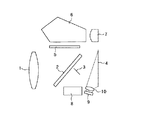
図1には、本発明の第1実施形態であるカメラの構成を示している。この図において、1は撮影レンズである。2は撮影レンズ1を透過した光をファインダー側へ導く主ミラーで、中央部は半透過ミラーとなっている。この半透過部を透過した光は、サブミラー3にてAFユニット8へと導かれる。
【0021】
4はフィルム面で、ストロボを用いたストロボ撮影時は、このフィルム面4にて反射した光を調光レンズ10を介して調光センサーユニット9で検出し、ストロボ光量の制御を行なっている。
【0022】
5は、ファインダー上に撮影像を形成し撮影者がピントの合った時を判断できるようにしたフォーカシングスクリーン、6はペンタプリズム、7はアイピースレンズである。
【0023】
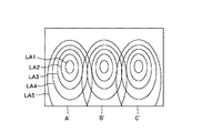
調光センサーユニット9は、図2に示すように、A,B,Cの3つのセンサー(ストロボ光量検出手段)に分割され、フィルム面4のストロボ反射光を3領域で検出できるようになっている。図3には、調光センサー9の3つの光量検出可能領域と、各光量検出可能領域における調光センサー9の感度分布とをフィルム面に対応させて表示している。この図において、調光センサー9のうちセンサーAは光量検出可能領域A′を、センサーBは光量検出可能領域B′を、センサーCは光量検出可能領域C′をそれぞれ有する。
【0024】
また、各光量検出可能領域内の中央(等感度曲線LA1に囲まれた部分の中央)は最大センサー感度を有し、外側ほどセンサーユニット9へ導かれる光量が低下するためにセンサー感度も低下する。具体的には、等感度曲線LA1上の部分のセンサー感度は中央部に対し0.3段低下し、等感度曲線LA2上の部分のセンサー感度は中央部に対し0.6段低下する。また、等感度曲線LA3上の部分のセンサー感度は中央部に対し0.9段低下し、等感度曲線LA4上の部分のセンサー感度は中央部に対し1.2段低下する。さらに、等感度曲線LA5上から外側の部分のセンサー感度は中央部に対し1.5段低下する。
【0025】
また、この感度分布において、上部の等感度曲線の間隔が下部の等感度曲線の間隔よりも狭いのは、図1に示すように、調光センサーユニット9がフィルム面4に対して斜め下側に配置され、調光レンズ10とフィルム面4の上部との角度が調光レンズ10とフィルム面4の下部との角度よりも小さく、またフィルム面4に均一に光を与えたとしてもフィルム面4の上部からの反射光量は少なく、フィルム面4の下部からの反射光量は多いことによる。
【0026】
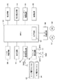
図4には、本実施形態のカメラの電気制御回路を示している。50はカメラ内の各種演算や制御を行うMPUであり、このMPU50内には、カメラの調整値や補正値等を記憶するEEPROM51が設けられている。52は不図示の多分割されたセンサーを持つ測光回路である。53は焦点検出回路で、図5に示すように撮影視野71内にa1〜e3までの15の焦点検出領域を有している。
【0027】
54はシャッター制御回路である。55は調光回路で、図2に示す3分割のセンサー9を有する。
【0028】
56はモーター制御回路で、フィルムの給送や巻戻しを行うモータ(M1)57と、ミラー駆動やシャッターのメカ的なチャージを行うモータ(M2)58を駆動制御する。
【0029】
59はレンズ制御回路で、不図示のフォーカス駆動や絞り駆動を行なっている。60はカメラの状態や演算されたTV値やAU値などを表示する表示回路である。61はストロボ撮影時に制御されるストロボ発光制御回路で、SWXがシャッターの先幕走行にてオンすることによりストロボ発光を開始させる。なお、MPU50およびストロボ発光制御回路61が請求の範囲にいう制御手段に相当する。
【0030】
62はカメラの設定操作やメカ的作動を検知するスイッチ検出回路で、測光や焦点検出等をスタートさせるSW1や、レリーズ動作を開始させるSW2や、焦点検出領域の選択スイッチSW3や、TV値やAV値を設定するメイン電子ダイヤル63およびサブ電子ダイヤル64等により構成される。
【0031】
ここで、メイン電子ダイヤル63及びサブ電子ダイヤル64は焦点検出領域選択設定時にも用いられる。その選択設定方法を図6を用いて簡単に説明する。図6(1)及び(2)は、15の焦点検出領域のうちカメラが合焦動作を行う合焦領域を任意に設定する場合の設定方法を示しており、(1)に示す状態で焦点検出領域選択スイッチSW3を押すと、前回設定された合焦領域がb2であればb2が選択されていることを表示回路60によりカメラ外部のLCA表示器もしくは公知のファインダー内スーパーインポーズ表示にて点灯表示する。この状態で、例えばメイン電子ダイヤル63を2クリック右回転させると、この点灯表示はb2→c2→d2へと右方向に移動し、焦点検出領域d2が今回の合焦領域として設定される。さらにこの状態でサブ電子ダイヤル64を1クリック右回転させると、(2)に示すように、点灯表示はd2→d3へと下方向に移動し、焦点検出領域d3が今回の合焦領域として設定される。
【0032】
また、同様に、メイン電子ダイヤル63を左回転により左方向への合焦領域の移動設定が可能であり、サブ電子ダイヤル64の左回転により上方向への合焦領域の移動設定が可能である。
【0033】
さらに、図6(1)のd2設定状態からさらにメイン電子ダイヤル63を右方向に2クリック回転させた場合や、図6(2)のd3設定状態よりさらにサブ電子ダイヤルを右方向に1クリック回転させた場合は、図6(3)に示すように、15の焦点検出領域のうち外周部の領域全てを点灯表示され、カメラが15の焦点検出領域の中から被写体に応じて自動的に焦点検出領域を選択し、合焦動作を行う焦点検出領域自動選択モードが設定される。
【0034】
なお、焦点検出領域自動選択モードに設定された状態から、上記と逆の操作によって再度任意の焦点検出領域を合焦領域として設定することも可能である。
【0035】
図7には、本カメラにおける撮影視野71と上記15の焦点検出領域a1〜e3と調光センサーA,B,Cの光量検出可能領域A′,B′,C′との関係を示している。すなわち、焦点検出領域a2はセンサーAの光量検出可能領域A′のうち最大センサー感度を有する部分に配置され、焦点検出領域c2はセンサーBの光量検出可能領域B′のうち最大センサー感度を有する部分に配置され、焦点検出領域e2はセンサーCの光量検出可能領域C′のうち最大センサー感度を有する部分に配置されるように調光レンズ10の光学配置がなされている。
【0036】
また、焦点検出領域a1,c1,e1はそれぞれ光量検出可能領域A′,B′,C′のうち最大センサー感度に対して1.2段アンダーのセンサー感度を有する部分(等感度曲線LA4上)に配置され、焦点検出領域a3,c3,e3はそれぞれ光量検出可能領域A′,B′,C′のうち最大センサー感度に対して0.9段アンダーのセンサー感度を有する部分(等感度曲線LA3上)に配置されている。また、焦点検出領域b2は光量検出可能領域A′,B′のうち最大センサー感度に対して1.2段アンダーのセンサー感度を有する部分(等感度曲線LA4上)に配置され、焦点検出領域d2は光量検出可能領域B′,C′のうち最大センサー感度に対して1.2段アンダーのセンサー感度を有する部分(等感度曲線LA4上)に配置されている。
【0037】
さらに、焦点検出領域b1,b3は光量検出可能領域A′,B′のうち最大センサー感度に対して1.5段アンダーのセンサー感度を有する部分(等感度曲線LA5の近傍)に配置され、焦点検出領域d1,d3は光量検出可能領域B′,C′のうち最大センサー感度に対して1.5段アンダーのセンサー感度を有する部分(等感度曲線LA5の近傍)に配置されている。
【0038】
なお、15の焦点検出領域a1〜e3および各センサー部A,B,Cは、画面中央Gラインに対し、左右対称となるように配置されている。
【0039】
次に、以上のように構成されたカメラの動作について図8および図9のフローチャートを用いて説明する。なお、図8における丸囲みのA〜Dのラインは、図9における丸囲みのA〜Dのラインにつながっている。
【0040】
カメラの電源をオンすると動作を開始し(#100)、#101にて測光、焦点検出等を開始させるSW1の検知を行う。ここでSW1がオンであることを検知すると、#102へ移行し、焦点検出領域選択モードが、図6(1),(2)にて説明したように撮影者が任意に焦点検出領域を選択し、その選択された焦点検出領域にて合焦動作を行なう焦点検出領域任意選択モードか、全焦点検出領域のうちカメラが自動的に被写体の状況を判断して選択した焦点検出領域で合焦動作を行う焦点検出領域自動選択モードかを判別する。次に、#103では、通常のAF撮影か、ストロボ撮影かの判別も行なう。なお、本実施形態におけるストロボ撮影は、カメラに内蔵されるストロボを使用しても、外部に接続されるクリップオンタイプのストロボ装置を使用してもよい。
【0041】
続いて#104では、不図示の多分割測光センサーを含む測光回路52を駆動し、外光の明るさを測光する。
【0042】
次に、#105では、#104で測光した値から演算して求めたTV値、AV値や、#102で判別した焦点検出領域選択モード、#103で判別したストロボ撮影か否か等の表示も、不図示のファインダー内表示器や外部表示器を表示回路60にて駆動して行う。
【0043】
次に、#106では、#102で判別された焦点検出領域選択モードに応じて焦点検出回路53を駆動すると共にレンズ制御回路59内のフォーカス駆動装置を駆動しながら焦点検出および合焦動作を行う。
【0044】
また、この動作とほぼ同時に、#107での合焦判別も行ない、合焦状態でなければ#104に戻り、上記の動作をくり返す。合焦状態であれば#108に移行し、合焦した旨を撮影者に知らせる表示を行う。ここでの表示は、公知のファインダー内スーパーインポーズ表示等によって行われ、任意選択点での合焦時はその任意選択点(合焦領域)が点灯表示される一方、自動選択時での合焦時はカメラが自動的に選択した合焦領域が点灯表示されるとともに、所定の被写界深度内に入る焦点検出領域を含む複数の合焦領域が点灯表示される場合もある。
【0045】
次に、#109でストロボの設定状態や充電が完了されているか等の判別を行うとともにストロボ撮影を行うか否かの判定を行ない、ストロボ撮影でなければ#122へ移行する。ストロボ撮影であると判定したときは#110に進んで、合焦した状態のレンズ1の停止位置から被写体までの距離を求め、その距離が所定値より近距離側である場合には#111に進んで、RAM上に近距離フラグをセットし、距離が所定値より遠距離側である場合には#112に進んで、RAM上に遠距離フラグをセットする。
【0046】
続いて#113に移行し、#108にて表示した合焦領域が1つか複数かの判定を行い、1つである場合には#114で#111又は#112にてセットした距離フラグを読み取り、近距離フラグがセットされていた場合には#115にて合焦領域に対する調光センサーA,B,Cの目標検出受光量の補正量を、図11に示すように予め設定されたデータの中から読み取る。また、遠距離フラグがセットされていた場合には#116にて合焦領域に対する調光センサーA,B,Cの目標検出受光量の補正量を、図10に示すように予め設定されたデータの中から読み取る。
【0047】
ここで、図10及び図11に示すように、本実施形態では、15の焦点検出領域a1〜e3に対し、各焦点検出領域が合焦領域として選択された場合における3つの調光センサーA,B,Cの目標検出光量に対するそれぞれの補正データを被写体が近距離の場合と遠距離との場合とに分けて持っている。
【0048】
この補正データでは、焦点検出領域a2が合焦領域として選択された場合の調光センサーAの目標検出受光量の補正量、焦点検出領域c2が合焦領域として選択された場合の調光センサーBの目標検出受光量の補正量、焦点検出領域e2が合焦領域として選択された場合の調光センサーCの目標検出受光量の補正量をそれぞれ0段とし、上記各場合における光量検出可能領域に合焦領域を含まない調光センサーの補正量を+1.0段にしている。
【0049】
ここで、補正量0段とは、フィルムのISO感度や絞り値等より算出されるそのままの値で目標検出受光量が設定されることを意味し、補正量+1.0段とは、上記値より+1.0段多い目標検出受光量が設定されることを意味する。これは中央被写体にピントを合わせ、中央被写体をストロボ適正光量で撮影しようとした場合、中央被写体がかなり遠く、それより近い距離における左又は右に物体があるようなシーンでは、その左又は右の物体が異常にオーバーな露出になるのを防止するために設定されるものである。
【0050】
しかしながら、上記焦点検出領域a2,c2,e2以外の焦点検出領域が合焦領域として選択されストロボ撮影するような場合には、調光センサーの感度分布が大きく影響し、例えば、焦点検出領域b1が合焦領域として選択された場合に、焦点検出領域a2が選択された場合と同じセンサーAの目標検出受光量にてストロボ撮影制御を行うと、焦点検出領域a2が選択された場合に対して1.5段分ストロボ光を多く受光しないと調光センサーAにおける実検出受光量が同一とならないため、被写体に多すぎるストロボ光量が与えられることになり、露光オーバーの写真となってしまう。
【0051】
このため、本実施形態では、光量検出可能領域内に合焦領域を含む調光センサーに対して、その合焦領域が配置された部分での調光センサーの最大感度からの感度低下分の値を補正量として設定し、光量検出可能領域内に合焦領域を含まない調光センサーに対しては、上記補正量より1段オーバーの重み付けを行う補正量を設定している。また、複数の調光センサーの光量検出可能領域内に配置された焦点検出領域が合焦領域として選択された場合は、それら複数の調光センサーを主として補正がかかるように設定している。つまり、焦点検出領域b1〜b3が選択されたときは調光センサーA,Bを主として、焦点検出領域d1〜d3が選択されたときは調光センサーB,Cを主として補正の重み付けが行なわれる。また、遠距離時と近距離時とでは、光量検出可能領域内に合焦領域を含む調光センサーに対する補正量が異なる。すなわち、遠距離時は被写体の大きさも小さく、調光センサーの感度分布が大きく影響しやすいため、ある程度感度分布が優先される補正量となっているが、近距離時は、被写体が人物の場合等、選択された合焦領域近傍にもストロボ光を反射する被写体があったり、反射光も遠距離時に比べて多く調光センサーに入り易くなったりする。このため、光量検出可能領域内に合焦領域を含む調光センサーの補正量は、近距離時の補正量が遠距離時の補正量の約半分となるように設定されている。
【0052】
なお、以上の補正データは、MPU50内のEEPROM51に予め書き込まれており、ストロボ発光制御時に適時読み取られ、処理される。
【0053】
フローチャートに戻って、#113で、#108にて表示した合焦領域が複数である場合には、#117に進み、#114と同様に#111又は#112にてセットした距離フラグを読み取る。近距離フラグがセットされている場合には、#118に進み、上記複数の合焦領域の全てに対する調光センサーA,B,Cの目標検出受光量の補正量を図11のデータから読み取り、また距離フラグが遠距離にセットされている場合には、#119に進み、上記複数の合焦領域の全てに対する調光センサーA,B,Cの目標検出受光量の補正量を図10のデータから読み取る。次に、#120の補正量再決定ステップに移行し、ここでは、#118又は#119にて読み取った複数の補正データから最終的に用いる補正量を算出する。
【0054】
ここでの算出方法としては、例えば遠距離時に、上部の焦点検出領域a1,b1,c1,d1,e1の全てが合焦領域として選択された場合、各調光センサーの補正量として最も少ない値を算出する。すなわち、調光センサーAに対する補正量は、焦点検出領域a1の−1.2段と焦点検出領域b1の−1.5段のうち少ない方の−1.5段を採用し、同様に調光センサーBに対する補正量は、焦点検出領域b1,d1の−1.5段および焦点検出領域c1の−1.2段のうち最も少ない−1.5段を採用する。また、調光センサーCに対する補正量は、焦点検出領域d1,e1の−1.5段を採用し、最終的な各調光センサーA,B,Cの補正量として−1.5段を採用する。
【0055】
また、近距離時に、左側の焦点検出領域a1,a2,a3の全てが合焦領域として選択された場合、調光センサーAの補正量は、焦点検出領域a1,a2,a3の−1.2段,0段,−0.6段のうち最も小さい−1.2段を採用し、他の緒光センサーB,Cに対する補正量はその値に対して+1段の重み付けを用い、最終的な調光センサーの補正量として、センサーAは−1.2段、センサーB,Cは−0.2段を採用する。
【0056】
前記#115、#116、#118、#119にてそれぞれ決定された補正量は、#121にてストロボ発光制御回路61にセットされる。これにより、光量検出可能範囲内に合焦領域を含む調光センサーに対してはその合焦領域が配置された部分のセンサー感度に応じた目標検出受光量がセットされ、光量検出可能範囲内に合焦領域を含まない調光センサーに対しては上記目標検出受光量に対して1段オーバーの目標検出受光量がセットされることになる。
【0057】
次に#122に移行し、露光動作へ継続させるか否かの判断をSW1のオン・オフにより検知し、オフであれば各演算値や補正値等をクリアして#101へ戻る。オンであれば#123で露光動作を開始するか否かをSW2のオン・オフで判断し、オフならば#122へ戻り、SW1がオン中であれば、この#122と#123をくり返してSW2のオンを待つ。
【0058】
#123でSW2がオンされると露光動作を開始する。そして、#124でモーター制御回路56を介してモータ(M2)58を駆動し、ミラーをアップさせると共に、#125でレンズ制御回路59内の絞りを駆動し、所定絞り値に設定する。続いて#126でシャッター制御回路54にシャッター先幕駆動を行わせ、#127へと移行する。
【0059】
#127では、#109と同様にして再度ストロボ撮影状態であるか否かの判定を行い、ストロボ撮影設定状態でなければ#131へ移行し、通常のAE撮影として、TV値に従った秒時にて、シャッター制御回路54にシャッター後幕駆動を行わせる。
【0060】
#127でストロボ撮影状態と判断すると、#128でストロボ制御回路61内のSW4のオンを待ち、SWXがオンすると#129にてストロボの発光を開始する。
【0061】
次いで#130では、3つの調光センサーA,B,Cにより検出されるフィルム面4でのストロボ反射光をモニター積分し、いずれかの調光センサーの積分値(実検出受光量)が、#121にてストロボ発光制御回路61にセットされたその調光センサーの目標検出受光量(調光値)に達したときはストロボ発光を停止させる。
【0062】
こうして合焦領域が調光センサーの光量検出可能領域内におけるいずれの検出感度を有する部分で選択されても、確実に適正なストロボ光露出を得ることができる。したがって、本実施形態のように、焦点検出領域a1〜e3が15設けられても3つの調光センサーA,B,Cを設けるだけで、選択される合焦領域の位置にかかわらず適正なストロボ光露出を得ることができる。
【0063】
ストロボ発光停止と同時に、#131にてストロボ秒時、通常同調秒時と言われる秒時にてシャッターの後幕駆動を行い、露光動作を完了させる。その後#132にてモーター制御回路56を介しモータ(M2)58を駆動してミラーのダウンやシャッターの初期位置へのチャージなどメカのチャージが行われ、それとほぼ同時に#133にてモータ(M1)57も駆動してフィルムの巻き上げを行い、#134にてフローを終了する。
【0064】
なお、本実施形態では、焦点検出領域を15設け、調光センサーを3つ設けた場合について説明したが、本発明における焦点検出領域や調光センサーの数はこれに限られるものではない。
【0065】
【発明の効果】
以上説明したように、本発明によれば、ストロボ光量検出手段の光量検出可能領域のうち合焦領域が配置された部分の検出感度に応じてストロボ光量検出手段の目標検出受光量を設定するようにしているので、合焦領域の位置におけるストロボ光量検出手段の検出感度にかかわらず確実に適正なストロボ光露出を得ることができる。したがって、焦点検出領域が多数設けられても少ない数のストロボ光量検出手段を設ければ足りることになり、カメラの低コスト化およびコンパクト化を図ることができる。
【0066】
なお、上記発明において合焦領域の選択数や被写体距離に応じてストロボ光量検出手段の目標検出受光量を設定するようにすれば、合焦領域の選択方式や被写体距離(つまりは撮影画面内での被写体の大きさ)にかかわらず、ストロボ発光量のばらつきや露出オーバーを防止することができる。
【0067】
また、合焦領域が光量検出可能領域内で複数選択されたときに、これら複数の合焦領域が配置された部分のストロボ光量検出手段の検出感度のうち最も低い検出感度に応じてストロボ光量検出手段の目標検出受光量を設定するようにすれば、各合焦領域に対応する検出感度が異なる場合でも、露出オーバーとなるのを確実に防止することができる。
【0068】
さらに、ストロボ光量検出手段が複数設けられているとともに、各ストロボ光量検出手段の光量検出可能領域内に焦点検出領域が配置されている場合に、光量検出可能領域内に合焦領域が配置されたストロボ光量検出手段に所定の重み付けをして各ストロボ光量検出手段の目標検出受光量を設定するようにすれば、合焦した主被写体に対して適正なストロボ光露出を得ることができるとともに、主被写体よりも近い位置にある被写体に対して露出オーバーになるのを防止できる。
また、目標検出受光量のデータを記憶する消去書き込み可能なメモリを設ければ、メインプログラムを変更することなく簡単にデータの修正等を行うことができる。
【図面の簡単な説明】
【図1】本発明の第1実施形態であるカメラの構成図である。
【図2】上記カメラに用いられる調光センサーの正面図である。
【図3】上記調光センサーの感度分布図である。
【図4】上記カメラの電気制御回路のブロック図である。
【図5】上記カメラの焦点検出領域の配置図である。
【図6】上記焦点検出領域における合焦領域選択方法の説明図である。
【図7】上記焦点検出領域と調光センサーの感度分布との関係を示す説明図である。
【図8】上記カメラの動作フローチャートである。
【図9】上記カメラの動作フローチャートである。
【図10】上記調光センサーの目標検出受光量の補正データ(遠距離時)を示す表図である。
【図11】上記調光センサーの目標検出受光量の補正データ(近距離時)を示す表図である。
【図12】従来のカメラにおける焦点検出領域と調光センサーの感度分布との関係を示す説明図である。
【図13】従来の調光センサーの目標検出受光量の補正データを示す表図である。
【符号の説明】
1 撮影レンズ
2 主ミラー
3 サブミラー
4 フィルム面
5 フォーカシングスクリーン
6 ペンタプリズム
7 アイピースレンズ
9 調光センサーユニット
10 調光レンズ
A,B,C 調光センサー
A′,B′,C′ (調光センサーの)光量検出可能領域
LA1〜LA6 等感度曲線
a1〜e3 焦点検出領域[0001]
BACKGROUND OF THE INVENTION
The present invention relates to strobe light emission control in a camera having a plurality of focus detection areas.
[0002]
[Prior art]
The relationship between a plurality of focus detection areas in a conventional camera and a light control sensor (strobe light amount detecting means) for detecting the amount of light incident on the photographing screen is as shown in FIG. 12, for example. That is, the dimming sensor unit in which the three dimming sensors are divided and formed has three light quantity detectable areas A ′, B ′, and C ′ corresponding to the respective dimming sensors. Among them, focus detection areas SL, SC, SR are arranged in the central portion having the maximum detection sensitivity. In addition, the sensor sensitivity decreases toward the outside in each light quantity detectable region, and the portions on the curves LA1 to LA5 in each light quantity detectable region have the same sensor sensitivity.
[0003]
In the above camera, a focus area can be selectively set from a plurality of focus detection areas, and a dimming sensor having a light amount detectable area including the selected focus area is selected. The target detected light reception amount by the selected light control sensor is determined from the ISO sensitivity of the film, the aperture value, etc., and for the light control sensor having a light amount detectable region that does not include the in-focus region, the target The target detected light reception amount is corrected so that it exceeds the detected light reception amount uniformly by a predetermined amount.
[0004]
For example, when the focusing operation is performed in the center focus detection area SC, it is determined that there is a person or subject in the center, and weighting is performed with the center sensor B as the center so that the center portion has an appropriate flash light emission amount. As shown in FIG. 13, the target detected light reception amount correction amount of 0 strobe light quantity is set for sensor B, and the +1.0 step target detection light reception amount correction amount is set for sensors A and C. Is done.
[0005]
The zero correction amount set for the sensor B means that the target detected light reception amount is set as it is calculated from the ISO sensitivity, aperture value, etc. of the film. The set correction amount +1.0 step means that a target detected light reception amount that is +1.0 step higher than the above value is set. This is because if you focus on the center subject and try to shoot the center subject with the appropriate amount of strobe light, in a scene where the center subject is far away and there is an object on the left or right at a closer distance, the left or right It is set to prevent the object from being overexposed abnormally.
[0006]
Similarly, when the focusing operation is performed in the left focus detection area SL, the sensor A is weighted with 0 correction amount and the sensors B and C are weighted with correction amount +1.0 step to detect the right focus. When the focusing operation is performed in the region SR, the sensor C is weighted with 0 correction amount, and the sensors A and B are weighted with correction amount +1.0 step.
[0007]
In this way, after setting the target detection light reception amount of each light control sensor, strobe light is emitted, and when the detection light reception amount of any sensor reaches the target detection light reception amount set for that sensor, the flash emission stops Is done.
[0008]
[Problems to be solved by the invention]
By the way, as shown in the example of FIG. 12, if the number of focus detection areas is relatively small and corresponds to the number of light quantity detectable areas (that is, the number of dimming sensor divisions) substantially one-to-one, complicated control is particularly performed. There is no need.
[0009]
However, recent cameras tend to greatly increase the number of focus detection areas. If the number of focus detection areas is equal to the number of dimming sensor divisions, the cost of the dimming sensor will increase.
[0010]
In addition, when the number of focus detection areas is increased, the focus detection device becomes larger, and therefore the light control sensor must be disposed close to the film surface. When the light control sensor is brought closer to the film surface, for example, the light control sensor sensitivity with respect to the center of the film surface and the light control sensor sensitivity with respect to the upper and lower portions of the film are greatly different. Strobe control cannot be performed uniformly as described above depending on whether the focus detection area arranged in the low sensitivity portion is selected as the focusing area.
[0011]
In other words, when the focus detection area at the upper and lower parts of the film surface that has a sensitivity greatly reduced with respect to the maximum sensor sensitivity is selected as the focus area, the focus detection area at the center of the film surface having the maximum sensor sensitivity is adjusted. When the strobe light emission control is performed in the same way as when the focus area is selected, if the amount of strobe light is not received on the upper and lower parts of the film due to the low sensor sensitivity, the detected light reception amount of the light control sensor will reach the maximum sensor sensitivity. On the other hand, since the target detected light reception amount that has been set is not reached, a considerably large amount of strobe light is given to the subject, and an overexposed photo is taken.
[0012]
In addition, when a plurality of in-focus areas are selected by the automatic in-focus area selection function, only one in-focus area with high reliability is extracted from these in-focus areas, and this extracted in-focus area corresponds. All the focus detection areas of the light control sensor are low because the target light reception amount of the light control sensors other than the light control sensor is corrected so that the target light reception amount of the light control sensor exceeds the predetermined amount. When it is a sensitive portion, an overexposed photo is taken as described above.
[0013]
Furthermore, the sensitivity distribution of the light control sensor is greatly influenced by the size and distance of the subject, resulting in a large difference in the amount of flash emission, resulting in variations in the captured flash emission photograph.
[0014]
[Means for Solving the Problems]
In order to solve the above-described problems, the present invention has a strobe light amount detecting means for detecting the amount of strobe light received on the photographing surface, and a plurality of focal points within the light amount detectable region of the strobe light amount detecting means in the photographing surface. In a camera in which a detection area is arranged and a focus area can be selected from these focus detection areas, the detection sensitivity of the strobe light quantity detection means in the part where the selected focus area is arranged among the light quantity detection areas is set. Correspondingly, there is provided control means for setting the target detected light reception amount of the strobe light amount detecting means.
[0015]
Specifically, the focus detection area includes a predetermined sensitivity portion in which the strobe light amount detection means has a predetermined detection sensitivity (for example, maximum detection sensitivity) and a different sensitivity portion having a detection sensitivity different from the predetermined detection sensitivity in the light amount detectable region. If the selected focus area is located in the different sensitivity area, the flash area is detected according to the difference between the detection sensitivity of the strobe light amount detecting means and the predetermined detection sensitivity in the different sensitivity area. The target detection light reception amount of the light amount detection means is set, and the flash emission is stopped when the actual detection light reception amount of the strobe light amount detection means reaches the target detection light reception amount. Thus, even when the in-focus area is selected in the low-sensitivity portion of the strobe light amount detecting means, an appropriate strobe light exposure is surely obtained, and one strobe light amount detecting means is provided for a plurality of focus detection areas. I will try to do it.
[0016]
In the above invention, the target detected light reception amount of the strobe light amount detecting means is set according to the number of selected focus areas, and even when only one focus area is arbitrarily selected by the photographer, automatic focusing is performed. Even when a plurality of areas are selected by the area selection function, an optimum strobe light exposure according to each case may be obtained. Further, by setting the target detected light reception amount of the strobe light amount detecting means in accordance with the subject distance, it is possible to suppress variations in the strobe light emission amount due to the subject distance (that is, the size of the subject in the shooting screen). Good.
[0017]
In addition, when a plurality of in-focus areas are selected in the light intensity detectable area, the strobe light intensity detection is performed according to the lowest detection sensitivity among the detection sensitivities of the strobe light intensity detecting means in the portion where the plurality of in-focus areas are arranged. It is desirable to set the target detected light reception amount of the means so as to reliably prevent overexposure even when the detection sensitivity corresponding to each in-focus area is different.
[0018]
Furthermore, when a plurality of strobe light quantity detection means are provided and a focus detection area is arranged in the light quantity detectable area of each strobe light quantity detection means, the focusing area is arranged in the light quantity detectable area. A predetermined weight is set to the strobe light amount detecting means to set a target detected light amount of each strobe light amount detecting means, and an actual detected light amount of any of the plurality of strobe light amount detecting means is a target detection of this strobe light amount detecting means. Strobe light emission is stopped when the amount of received light is reached, so that proper flash light exposure can be obtained for the focused main subject and overexposure is performed on subjects that are closer to the main subject. It would be desirable to be able to prevent it.
[0019]
It is desirable to provide an erasable and writable memory for storing the target detected light reception amount data so that the data can be easily corrected without changing the main program.
[0020]
DETAILED DESCRIPTION OF THE INVENTION
(First embodiment)
FIG. 1 shows the configuration of a camera according to the first embodiment of the present invention. In this figure, 1 is a taking lens.
[0021]
Reference numeral 4 denotes a film surface. At the time of strobe photography using a strobe, light reflected by the film surface 4 is detected by a light
[0022]
Reference numeral 5 denotes a focusing screen on which a photographed image is formed on the viewfinder so that the photographer can determine when the subject is in focus, 6 is a pentaprism, and 7 is an eyepiece lens.
[0023]
As shown in FIG. 2, the light
[0024]
In addition, the center in each light quantity detectable region (the center of the portion surrounded by the isosensitivity curve LA1) has the maximum sensor sensitivity, and the sensor sensitivity decreases because the light amount guided to the
[0025]
Also, in this sensitivity distribution, the interval between the upper isosensitivity curves is narrower than the interval between the lower isosensitivity curves, as shown in FIG. Even if the angle between the dimming
[0026]
FIG. Shows an electric control circuit of the camera of the present embodiment.
[0027]
[0028]
A
[0029]
[0030]
[0031]
Here, the main
[0032]
Similarly, it is possible to set the movement of the focusing area in the left direction by rotating the main
[0033]
Further, when the main
[0034]
Note that it is also possible to set an arbitrary focus detection region as the focus region again by performing the reverse operation to the focus detection region automatic selection mode.
[0035]
FIG. 7 shows the relationship between the field of
[0036]
The focus detection areas a1, c1, and e1 are portions having sensor sensitivity that is 1.2 steps lower than the maximum sensor sensitivity in the light quantity detectable areas A ′, B ′, and C ′ (on the isosensitivity curve LA4). The focus detection areas a3, c3, and e3 are portions where the sensor sensitivity is 0.9 step below the maximum sensor sensitivity (isosensitivity curve LA3 (Above). Further, the focus detection area b2 is arranged in a portion (on the isosensitivity curve LA4) having a sensor sensitivity that is 1.2 steps lower than the maximum sensor sensitivity in the light quantity detectable areas A ′ and B ′, and the focus detection area d2 Is disposed in a portion (on the isosensitivity curve LA4) having a sensor sensitivity that is 1.2 steps below the maximum sensor sensitivity in the light quantity detectable regions B ′ and C ′.
[0037]
Further, the focus detection areas b1 and b3 are arranged in a portion (in the vicinity of the isosensitivity curve LA5) having a sensor sensitivity that is 1.5 steps below the maximum sensor sensitivity in the light quantity detectable areas A ′ and B ′. The detection areas d1 and d3 are arranged in a portion (in the vicinity of the isosensitivity curve LA5) having a sensor sensitivity that is 1.5 steps below the maximum sensor sensitivity in the light quantity detectable areas B ′ and C ′.
[0038]
Note that the fifteen focus detection areas a1 to e3 and the sensor portions A, B, and C are arranged to be symmetrical with respect to the screen center G line.
[0039]
Next, the operation of the camera configured as described above will be described with reference to the flowcharts of FIGS. The circled lines A to D in FIG. 8 are connected to the circled lines A to D in FIG. 9.
[0040]
When the camera is turned on, the operation is started (# 100), and SW1 that starts photometry, focus detection, etc. is detected at # 101. If it is detected that SW1 is on, the process proceeds to # 102, and the photographer arbitrarily selects the focus detection area as described in FIGS. 6 (1) and (2). In the focus detection area arbitrary selection mode in which the focusing operation is performed in the selected focus detection area, or in the focus detection area selected by the camera automatically judging the situation of the subject among the all focus detection areas It is determined whether or not the focus detection area automatic selection mode is selected for operation. Next, in # 103, it is also determined whether normal AF shooting or flash shooting. Note that the flash photography in this embodiment may use a flash built in the camera or a clip-on type flash device connected to the outside.
[0041]
In
[0042]
Next, in # 105, the TV value and AV value obtained by calculation from the values measured in # 104, the focus detection area selection mode determined in # 102, the flash photography determined in # 103, and the like are displayed. Also, the
[0043]
Next, in # 106, the
[0044]
Almost at the same time as this operation, in-focus determination is performed in # 107. If the in-focus state is not obtained, the process returns to # 104 and the above operation is repeated. If it is in focus, the process proceeds to # 108, and a display notifying the photographer that the camera is in focus is displayed. The display here is performed by a well-known superimpose display in the finder, etc., and when the focus is at an arbitrarily selected point, the arbitrarily selected point (in-focus area) is lit on, while the focus at the time of automatic selection is displayed. At the time of in-focus, a focus area automatically selected by the camera is lit and displayed, and a plurality of focus areas including a focus detection area that falls within a predetermined depth of field may be lit and displayed.
[0045]
Next, in
[0046]
Subsequently, the process proceeds to # 113, where it is determined whether there is one or more in-focus areas displayed in # 108. If there is one, the distance flag set in # 111 or # 112 is read in # 114. If the short distance flag is set, the correction amount of the target detected light reception amount of the light control sensors A, B, and C for the in-focus area is set in
[0047]
Here, as shown in FIGS. 10 and 11, in the present embodiment, for the 15 focus detection areas a1 to e3, the three dimming sensors A, when each focus detection area is selected as the focus area, Each of the correction data for the target detected light amounts of B and C is divided into a case where the subject is a short distance and a case where the subject is a long distance.
[0048]
In this correction data, the correction amount of the target detected light reception amount of the light adjustment sensor A when the focus detection area a2 is selected as the focus area, and the light adjustment sensor B when the focus detection area c2 is selected as the focus area. The correction amount of the target detected light reception amount and the correction amount of the target detected light reception amount of the light control sensor C when the focus detection region e2 is selected as the focus region are each set to zero, and the light amount detection possible region in each of the above cases The correction amount of the light control sensor not including the focus area is set to +1.0.
[0049]
Here, the correction amount of 0 step means that the target detected light reception amount is set as it is calculated from the ISO sensitivity of the film, the aperture value, etc., and the correction amount +1.0 step is the above value. This means that a target detected light reception amount that is 1.0 stage higher than that is set. This is because if you focus on the center subject and try to shoot the center subject with the appropriate amount of strobe light, in a scene where the center subject is far away and there is an object on the left or right at a closer distance, the left or right It is set to prevent the object from being overexposed abnormally.
[0050]
However, when a focus detection area other than the focus detection areas a2, c2, and e2 is selected as the focus area and the stroboscopic image is taken, the sensitivity distribution of the light control sensor greatly affects, for example, the focus detection area b1 is When the stroboscopic imaging control is performed with the same target detected light reception amount of the sensor A as when the focus detection area a2 is selected when the focus detection area a2 is selected, 1 is obtained when the focus detection area a2 is selected. If the strobe light is not received in a large amount for five steps, the actual detected light reception amount in the light control sensor A is not the same, so that too much strobe light amount is given to the subject, resulting in an overexposed photograph.
[0051]
For this reason, in the present embodiment, for a dimming sensor that includes a focusing area within the light intensity detectable area, a value corresponding to a sensitivity decrease from the maximum sensitivity of the dimming sensor in a portion where the focusing area is arranged. Is set as a correction amount, and for a light control sensor that does not include an in-focus region within the light quantity detectable region, a correction amount that sets a weight that is one step over the correction amount is set. In addition, when the focus detection area arranged in the light quantity detectable area of the plurality of light control sensors is selected as the focus area, the plurality of light control sensors are set to be mainly corrected. That is, when the focus detection areas b1 to b3 are selected, the light adjustment sensors A and B are mainly used, and when the focus detection areas d1 to d3 are selected, the light adjustment sensors B and C are mainly used for correction weighting. Further, the correction amount for the light control sensor including the in-focus area in the light amount detectable area is different between the long distance and the short distance. In other words, the subject size is small at long distances, and the sensitivity distribution of the light control sensor is likely to be greatly affected, so the sensitivity distribution is given priority to some extent, but at short distances the subject is a person For example, there is an object that reflects the strobe light in the vicinity of the selected focusing area, and the reflected light is more likely to enter the light control sensor than at a long distance. For this reason, the correction amount of the light control sensor including the in-focus region within the light amount detectable region is set so that the correction amount at the short distance is about half of the correction amount at the long distance.
[0052]
The above correction data is written in advance in the
[0053]
Returning to the flowchart, if there are a plurality of in-focus areas displayed in # 108 in # 113, the process proceeds to # 117, and the distance flag set in # 111 or # 112 is read as in # 114. When the short distance flag is set, the process proceeds to # 118, and the correction amount of the target detected light reception amount of the dimming sensors A, B, C for all of the plurality of in-focus areas is read from the data of FIG. If the distance flag is set to a long distance, the process proceeds to step # 119, and the correction amount of the target detected light reception amount of the dimming sensors A, B, and C for all of the plurality of in-focus areas is shown in FIG. Read from. Next, the process proceeds to a correction amount
[0054]
As a calculation method here, for example, when all of the upper focus detection areas a1, b1, c1, d1, and e1 are selected as the focusing areas at a long distance, the smallest value as the correction amount of each light control sensor Is calculated. That is, the correction amount for the dimming sensor A is -1.5 stage, which is the smaller of the -1.2 stage of the focus detection area a1 and the -1.5 stage of the focus detection area b1. The correction amount for the sensor B employs the smallest −1.5 step among the −1.5 steps of the focus detection regions b1 and d1 and the −1.2 step of the focus detection region c1. In addition, the correction amount for the light control sensor C employs −1.5 steps for the focus detection areas d1 and e1, and the final correction amount for each light control sensor A, B, and C uses −1.5 steps. To do.
[0055]
Further, when all of the left focus detection areas a1, a2, and a3 are selected as the focus areas at a short distance, the correction amount of the light control sensor A is -1.2 of the focus detection areas a1, a2, and a3. The smallest -1.2 stage is adopted among the stage, 0 stage, and -0.6 stage, and the correction amount for the other optical sensors B and C uses a weight of +1 stage for the value, and finally As the correction amount of the light control sensor, the sensor A adopts -1.2 stage, and the sensors B and C adopt -0.2 stage.
[0056]
The correction amounts determined in # 115, # 116, # 118, and # 119 are set in the strobe light
[0057]
Next, the process proceeds to # 122, in which whether or not to continue the exposure operation is detected by turning on / off of SW1, and if it is off, the respective calculation values and correction values are cleared and the process returns to # 101. If it is on, whether or not the exposure operation starts in # 123 is determined by turning on / off of SW2, and if it is off, the process returns to # 122, and if SW1 is on, repeats # 122 and # 123. Wait for SW2 to turn on.
[0058]
When SW2 is turned on in # 123, the exposure operation is started. In
[0059]
In # 127, it is determined again whether or not the flash photography state is set in the same manner as in # 109. If it is not in the flash photography setting state, the process proceeds to # 131, and the normal AE photography is performed in seconds according to the TV value. Thus, the
[0060]
If it is determined in
[0061]
Next, in # 130, the strobe reflected light on the film surface 4 detected by the three light control sensors A, B, and C is monitor-integrated, and the integrated value (actual detected light reception amount) of any of the light control sensors is # When the target detected light reception amount (dimming value) of the light control sensor set in the strobe light
[0062]
Thus, even if the in-focus area is selected at a part having any detection sensitivity in the light quantity detectable area of the light control sensor, it is possible to surely obtain an appropriate strobe light exposure. Therefore, as in this embodiment, even if 15 focus detection areas a1 to e3 are provided, only three light control sensors A, B, and C are provided, and an appropriate strobe is provided regardless of the position of the selected focus area. Light exposure can be obtained.
[0063]
Simultaneously with the stop of the strobe light emission, the shutter rear curtain drive is performed in # 131 at the time of the strobe seconds and the time of the normal synchronization seconds, thereby completing the exposure operation. Thereafter, at # 132, the motor (M2) is passed through the
[0064]
In this embodiment, the case where 15 focus detection areas are provided and three light adjustment sensors are provided has been described. However, the number of focus detection areas and light adjustment sensors in the present invention is not limited to this.
[0065]
【The invention's effect】
As described above, according to the present invention, the target detected light reception amount of the strobe light amount detection unit is set according to the detection sensitivity of the portion where the in-focus region is arranged in the light amount detectable region of the strobe light amount detection unit. Therefore, an appropriate strobe light exposure can be surely obtained regardless of the detection sensitivity of the strobe light amount detecting means at the position of the focus area. Therefore, even if a large number of focus detection areas are provided, it is sufficient to provide a small number of strobe light quantity detection means, and the cost and size of the camera can be reduced.
[0066]
In the above invention, if the target detected light reception amount of the strobe light amount detecting means is set according to the number of selected focus areas and the subject distance, the focus area selection method and the subject distance (that is, within the shooting screen). Regardless of the size of the subject), it is possible to prevent variations in the amount of flash emission and overexposure.
[0067]
In addition, when a plurality of in-focus areas are selected in the light intensity detectable area, the strobe light intensity detection is performed according to the lowest detection sensitivity among the detection sensitivities of the strobe light intensity detecting means in the portion where the plurality of in-focus areas are arranged By setting the target detected light reception amount of the means, it is possible to reliably prevent overexposure even when the detection sensitivity corresponding to each in-focus area is different.
[0068]
Furthermore, when a plurality of strobe light quantity detection means are provided and a focus detection area is arranged in the light quantity detectable area of each strobe light quantity detection means, the focusing area is arranged in the light quantity detectable area. If a predetermined weight is applied to the strobe light amount detection means and the target detected light reception amount of each strobe light amount detection means is set, an appropriate strobe light exposure can be obtained for the focused main subject, and It is possible to prevent overexposure of a subject located closer to the subject.
Further, if an erasable and writable memory for storing the target detected light reception amount data is provided, the data can be easily corrected without changing the main program.
[Brief description of the drawings]
FIG. 1 is a configuration diagram of a camera according to a first embodiment of the present invention.
FIG. 2 is a front view of a light control sensor used in the camera.
FIG. 3 is a sensitivity distribution diagram of the light control sensor.
FIG. 4 is a block diagram of an electric control circuit of the camera.
FIG. 5 is a layout view of focus detection areas of the camera.
FIG. 6 is an explanatory diagram of a focus area selection method in the focus detection area.
FIG. 7 is an explanatory diagram showing a relationship between the focus detection region and the sensitivity distribution of the light control sensor.
FIG. 8 is an operation flowchart of the camera.
FIG. 9 is an operational flowchart of the camera.
FIG. 10 is a table showing correction data (at a long distance) of the target detected light reception amount of the dimming sensor.
FIG. 11 is a table showing correction data (at a short distance) of the target detected light reception amount of the light control sensor.
FIG. 12 is an explanatory diagram showing a relationship between a focus detection area and a sensitivity distribution of a light control sensor in a conventional camera.
FIG. 13 is a table showing correction data for a target detected light reception amount of a conventional light control sensor.
[Explanation of symbols]
1 Photo lens
2 Main mirror
3 Submirror
4 Film side
5 Focusing screen
6 Penta prism
7 Eyepiece lens
9 Light control sensor unit
10 Light control lens
A, B, C Light control sensor
A ', B', C 'Light intensity detection possible area
LA1-LA6 isosensitivity curve
a1 to e3 focus detection area
Claims (9)
前記光量検出可能領域のうち前記合焦領域が配置された部分の前記ストロボ光量検出手段の検出感度に応じて前記ストロボ光量検出手段の目標検出受光量を設定する制御手段を有することを特徴とするカメラ。And a strobe light amount detecting means for detecting the amount of strobe light received on the photographing surface, and a plurality of focus detection areas are arranged in the light amount detectable region of the strobe light amount detecting means in the photographing surface. In the camera that can select the focus area from
Control means for setting a target detected light reception amount of the strobe light amount detecting means in accordance with detection sensitivity of the strobe light amount detecting means in a portion where the focusing area is arranged in the light amount detectable region. camera.
前記制御手段は、前記合焦領域が前記異感度部分に配置されているときは、この異感度部分における前記ストロボ光量検出手段の検出感度と前記所定検出感度との差に応じて前記ストロボ光量検出手段の目標検出受光量を設定することを特徴とする請求項1に記載のカメラ。The focus detection areas are respectively arranged in a predetermined sensitivity part in which the strobe light amount detection means has a predetermined detection sensitivity and a different sensitivity part having a detection sensitivity different from the predetermined detection sensitivity in the light quantity detectable region,
When the focusing area is arranged in the different sensitivity portion, the control means detects the strobe light amount according to the difference between the detection sensitivity of the strobe light amount detection means in the different sensitivity portion and the predetermined detection sensitivity. 2. The camera according to claim 1, wherein a target detected light reception amount of the means is set.
前記制御手段は、光量検出可能領域内に前記合焦領域が配置されたストロボ光量検出手段に所定の重み付けをして前記各ストロボ光量検出手段の目標検出受光量を設定することを特徴とする請求項1から6のいずれかに記載のカメラ。A plurality of the strobe light quantity detection means are provided, and a focus detection area is arranged in a light quantity detectable area of each strobe light quantity detection means,
The control means sets a target detected light reception amount of each of the strobe light amount detecting means by giving a predetermined weight to the strobe light amount detecting means in which the focusing area is arranged in the light amount detectable area. Item 7. The camera according to any one of Items 1 to 6.
Priority Applications (4)
| Application Number | Priority Date | Filing Date | Title |
|---|---|---|---|
| JP20658097A JP3927655B2 (en) | 1997-07-31 | 1997-07-31 | camera |
| US09/122,382 US6035139A (en) | 1997-07-31 | 1998-07-27 | Camera for flash photography |
| DE69819248T DE69819248T2 (en) | 1997-07-31 | 1998-07-30 | Camera with automatic focus adjustment and TTL flash control |
| EP98114317A EP0895117B1 (en) | 1997-07-31 | 1998-07-30 | Camera with automatic focus and TTL flash control |
Applications Claiming Priority (1)
| Application Number | Priority Date | Filing Date | Title |
|---|---|---|---|
| JP20658097A JP3927655B2 (en) | 1997-07-31 | 1997-07-31 | camera |
Publications (2)
| Publication Number | Publication Date |
|---|---|
| JPH1152447A JPH1152447A (en) | 1999-02-26 |
| JP3927655B2 true JP3927655B2 (en) | 2007-06-13 |
Family
ID=16525765
Family Applications (1)
| Application Number | Title | Priority Date | Filing Date |
|---|---|---|---|
| JP20658097A Expired - Fee Related JP3927655B2 (en) | 1997-07-31 | 1997-07-31 | camera |
Country Status (4)
| Country | Link |
|---|---|
| US (1) | US6035139A (en) |
| EP (1) | EP0895117B1 (en) |
| JP (1) | JP3927655B2 (en) |
| DE (1) | DE69819248T2 (en) |
Families Citing this family (10)
| Publication number | Priority date | Publication date | Assignee | Title |
|---|---|---|---|---|
| JP4018218B2 (en) * | 1997-12-25 | 2007-12-05 | キヤノン株式会社 | Optical apparatus and distance measuring point selection method |
| JP4124874B2 (en) * | 1998-08-31 | 2008-07-23 | キヤノン株式会社 | camera |
| US6240253B1 (en) * | 1998-09-14 | 2001-05-29 | Minolta Co., Ltd. | Automatic focusing camera |
| US6240252B1 (en) * | 1998-09-14 | 2001-05-29 | Minolta Co., Ltd. | Camera |
| JP4756721B2 (en) * | 1999-05-17 | 2011-08-24 | キヤノン株式会社 | Camera focus detection device |
| US6949883B2 (en) | 2001-12-06 | 2005-09-27 | Seiko Epson Corporation | Electro-optical device and an electronic apparatus |
| CN100359357C (en) * | 2004-06-15 | 2008-01-02 | 佳能株式会社 | Image-taking apparatus |
| US7855636B2 (en) * | 2007-09-19 | 2010-12-21 | Honeywell International Inc. | Method for dynamically adjusting the sensitivity of a sensor in a security system |
| JP6562643B2 (en) * | 2015-02-04 | 2019-08-21 | キヤノン株式会社 | Imaging control apparatus and control method thereof |
| CN105847670B (en) | 2015-02-04 | 2019-06-21 | 佳能株式会社 | Electronic equipment, video camera controller and its control method |
Family Cites Families (6)
| Publication number | Priority date | Publication date | Assignee | Title |
|---|---|---|---|---|
| JPS5312337U (en) * | 1976-07-14 | 1978-02-01 | ||
| JP2704960B2 (en) * | 1988-05-20 | 1998-01-26 | キヤノン株式会社 | camera |
| US5111231A (en) * | 1989-07-27 | 1992-05-05 | Canon Kabushiki Kaisha | Camera system |
| DE4100481A1 (en) * | 1991-01-10 | 1992-07-16 | Schickedanz Willi | Sub-range measuring unit for camera with spot measurement - indicates spot in rangefinder and selects spot by eye movement of unit adjustment |
| JPH04257830A (en) * | 1991-02-12 | 1992-09-14 | Nikon Corp | Flash light dimming controller for camera |
| JPH04355733A (en) * | 1991-06-03 | 1992-12-09 | Nikon Corp | Automatic dimming device for camera |
-
1997
- 1997-07-31 JP JP20658097A patent/JP3927655B2/en not_active Expired - Fee Related
-
1998
- 1998-07-27 US US09/122,382 patent/US6035139A/en not_active Expired - Lifetime
- 1998-07-30 EP EP98114317A patent/EP0895117B1/en not_active Expired - Lifetime
- 1998-07-30 DE DE69819248T patent/DE69819248T2/en not_active Expired - Lifetime
Also Published As
| Publication number | Publication date |
|---|---|
| JPH1152447A (en) | 1999-02-26 |
| EP0895117B1 (en) | 2003-10-29 |
| DE69819248D1 (en) | 2003-12-04 |
| US6035139A (en) | 2000-03-07 |
| DE69819248T2 (en) | 2004-07-29 |
| EP0895117A1 (en) | 1999-02-03 |
Similar Documents
| Publication | Publication Date | Title |
|---|---|---|
| US6240253B1 (en) | Automatic focusing camera | |
| US5155581A (en) | Electronic still video camera | |
| JP3927655B2 (en) | camera | |
| JP4350199B2 (en) | camera | |
| JP5473493B2 (en) | Imaging apparatus and control method thereof | |
| JP2004004449A (en) | Exposure control system for camera | |
| JP4763941B2 (en) | Display control device, control method, program, and recording medium | |
| JPH09318871A (en) | Auxiliary light projecting device and focus detector | |
| JP4315708B2 (en) | camera | |
| JP4512173B2 (en) | Ranging device | |
| JP2006072084A (en) | Automatic focus detecting device and camera system | |
| JP6398315B2 (en) | Imaging device | |
| JP4426812B2 (en) | Digital camera | |
| JPH0534757A (en) | Camera | |
| JP2004179963A (en) | Imaging device | |
| JP3461220B2 (en) | Automatic control camera | |
| JP3131434B2 (en) | camera | |
| JP2006017854A (en) | Imaging apparatus and flash light emitting device | |
| JP3002502B2 (en) | Multi-dimming autofocus camera | |
| JP2884691B2 (en) | TTL automatic light control camera | |
| JP2001350171A (en) | Camera | |
| JP2004347678A (en) | Light receiving device for camera | |
| JP2000137161A (en) | Automatic focusing camera | |
| JP2005173386A (en) | Camera | |
| JPH11288016A (en) | Electronic control camera |
Legal Events
| Date | Code | Title | Description |
|---|---|---|---|
| A521 | Request for written amendment filed |
Free format text: JAPANESE INTERMEDIATE CODE: A523 Effective date: 20040730 |
|
| A621 | Written request for application examination |
Free format text: JAPANESE INTERMEDIATE CODE: A621 Effective date: 20040730 |
|
| A977 | Report on retrieval |
Free format text: JAPANESE INTERMEDIATE CODE: A971007 Effective date: 20060816 |
|
| TRDD | Decision of grant or rejection written | ||
| A01 | Written decision to grant a patent or to grant a registration (utility model) |
Free format text: JAPANESE INTERMEDIATE CODE: A01 Effective date: 20070227 |
|
| A61 | First payment of annual fees (during grant procedure) |
Free format text: JAPANESE INTERMEDIATE CODE: A61 Effective date: 20070305 |
|
| R150 | Certificate of patent or registration of utility model |
Free format text: JAPANESE INTERMEDIATE CODE: R150 |
|
| FPAY | Renewal fee payment (event date is renewal date of database) |
Free format text: PAYMENT UNTIL: 20100309 Year of fee payment: 3 |
|
| FPAY | Renewal fee payment (event date is renewal date of database) |
Free format text: PAYMENT UNTIL: 20110309 Year of fee payment: 4 |
|
| FPAY | Renewal fee payment (event date is renewal date of database) |
Free format text: PAYMENT UNTIL: 20120309 Year of fee payment: 5 |
|
| FPAY | Renewal fee payment (event date is renewal date of database) |
Free format text: PAYMENT UNTIL: 20130309 Year of fee payment: 6 |
|
| FPAY | Renewal fee payment (event date is renewal date of database) |
Free format text: PAYMENT UNTIL: 20140309 Year of fee payment: 7 |
|
| LAPS | Cancellation because of no payment of annual fees |