JP3927022B2 - REMOTE OPERATION DEVICE, REMOTE OPERATION SYSTEM, IMAGE DISPLAY METHOD, IMAGE DISPLAY PROGRAM FOR EXECUTE ON COMPUTER, COMPUTER-READABLE RECORDING MEDIUM CONTAINING IMAGE DISPLAY PROGRAM FOR EXECUTE ON COMPUTER - Google Patents
REMOTE OPERATION DEVICE, REMOTE OPERATION SYSTEM, IMAGE DISPLAY METHOD, IMAGE DISPLAY PROGRAM FOR EXECUTE ON COMPUTER, COMPUTER-READABLE RECORDING MEDIUM CONTAINING IMAGE DISPLAY PROGRAM FOR EXECUTE ON COMPUTER Download PDFInfo
- Publication number
- JP3927022B2 JP3927022B2 JP2001370262A JP2001370262A JP3927022B2 JP 3927022 B2 JP3927022 B2 JP 3927022B2 JP 2001370262 A JP2001370262 A JP 2001370262A JP 2001370262 A JP2001370262 A JP 2001370262A JP 3927022 B2 JP3927022 B2 JP 3927022B2
- Authority
- JP
- Japan
- Prior art keywords
- unit
- display
- operation input
- remote control
- rotating body
- Prior art date
- Legal status (The legal status is an assumption and is not a legal conclusion. Google has not performed a legal analysis and makes no representation as to the accuracy of the status listed.)
- Expired - Lifetime
Links
Images


Classifications
-
- G—PHYSICS
- G06—COMPUTING; CALCULATING OR COUNTING
- G06F—ELECTRIC DIGITAL DATA PROCESSING
- G06F3/00—Input arrangements for transferring data to be processed into a form capable of being handled by the computer; Output arrangements for transferring data from processing unit to output unit, e.g. interface arrangements
- G06F3/01—Input arrangements or combined input and output arrangements for interaction between user and computer
- G06F3/02—Input arrangements using manually operated switches, e.g. using keyboards or dials
- G06F3/023—Arrangements for converting discrete items of information into a coded form, e.g. arrangements for interpreting keyboard generated codes as alphanumeric codes, operand codes or instruction codes
- G06F3/0238—Programmable keyboards
-
- G—PHYSICS
- G06—COMPUTING; CALCULATING OR COUNTING
- G06F—ELECTRIC DIGITAL DATA PROCESSING
- G06F3/00—Input arrangements for transferring data to be processed into a form capable of being handled by the computer; Output arrangements for transferring data from processing unit to output unit, e.g. interface arrangements
- G06F3/01—Input arrangements or combined input and output arrangements for interaction between user and computer
- G06F3/02—Input arrangements using manually operated switches, e.g. using keyboards or dials
- G06F3/023—Arrangements for converting discrete items of information into a coded form, e.g. arrangements for interpreting keyboard generated codes as alphanumeric codes, operand codes or instruction codes
- G06F3/0231—Cordless keyboards
-
- G—PHYSICS
- G06—COMPUTING; CALCULATING OR COUNTING
- G06F—ELECTRIC DIGITAL DATA PROCESSING
- G06F3/00—Input arrangements for transferring data to be processed into a form capable of being handled by the computer; Output arrangements for transferring data from processing unit to output unit, e.g. interface arrangements
- G06F3/01—Input arrangements or combined input and output arrangements for interaction between user and computer
- G06F3/03—Arrangements for converting the position or the displacement of a member into a coded form
- G06F3/033—Pointing devices displaced or positioned by the user, e.g. mice, trackballs, pens or joysticks; Accessories therefor
- G06F3/0362—Pointing devices displaced or positioned by the user, e.g. mice, trackballs, pens or joysticks; Accessories therefor with detection of 1D translations or rotations of an operating part of the device, e.g. scroll wheels, sliders, knobs, rollers or belts
-
- H—ELECTRICITY
- H04—ELECTRIC COMMUNICATION TECHNIQUE
- H04N—PICTORIAL COMMUNICATION, e.g. TELEVISION
- H04N21/00—Selective content distribution, e.g. interactive television or video on demand [VOD]
- H04N21/40—Client devices specifically adapted for the reception of or interaction with content, e.g. set-top-box [STB]; Operations thereof
- H04N21/41—Structure of client; Structure of client peripherals
- H04N21/4104—Peripherals receiving signals from specially adapted client devices
- H04N21/4126—The peripheral being portable, e.g. PDAs or mobile phones
- H04N21/41265—The peripheral being portable, e.g. PDAs or mobile phones having a remote control device for bidirectional communication between the remote control device and client device
-
- H—ELECTRICITY
- H04—ELECTRIC COMMUNICATION TECHNIQUE
- H04N—PICTORIAL COMMUNICATION, e.g. TELEVISION
- H04N21/00—Selective content distribution, e.g. interactive television or video on demand [VOD]
- H04N21/40—Client devices specifically adapted for the reception of or interaction with content, e.g. set-top-box [STB]; Operations thereof
- H04N21/41—Structure of client; Structure of client peripherals
- H04N21/422—Input-only peripherals, i.e. input devices connected to specially adapted client devices, e.g. global positioning system [GPS]
- H04N21/42204—User interfaces specially adapted for controlling a client device through a remote control device; Remote control devices therefor
- H04N21/42206—User interfaces specially adapted for controlling a client device through a remote control device; Remote control devices therefor characterized by hardware details
- H04N21/42208—Display device provided on the remote control
-
- H—ELECTRICITY
- H04—ELECTRIC COMMUNICATION TECHNIQUE
- H04N—PICTORIAL COMMUNICATION, e.g. TELEVISION
- H04N21/00—Selective content distribution, e.g. interactive television or video on demand [VOD]
- H04N21/40—Client devices specifically adapted for the reception of or interaction with content, e.g. set-top-box [STB]; Operations thereof
- H04N21/41—Structure of client; Structure of client peripherals
- H04N21/422—Input-only peripherals, i.e. input devices connected to specially adapted client devices, e.g. global positioning system [GPS]
- H04N21/42204—User interfaces specially adapted for controlling a client device through a remote control device; Remote control devices therefor
- H04N21/42226—Reprogrammable remote control devices
-
- G—PHYSICS
- G08—SIGNALLING
- G08C—TRANSMISSION SYSTEMS FOR MEASURED VALUES, CONTROL OR SIMILAR SIGNALS
- G08C2201/00—Transmission systems of control signals via wireless link
- G08C2201/20—Binding and programming of remote control devices
- G08C2201/21—Programming remote control devices via third means
-
- G—PHYSICS
- G08—SIGNALLING
- G08C—TRANSMISSION SYSTEMS FOR MEASURED VALUES, CONTROL OR SIMILAR SIGNALS
- G08C2201/00—Transmission systems of control signals via wireless link
- G08C2201/30—User interface
-
- G—PHYSICS
- G08—SIGNALLING
- G08C—TRANSMISSION SYSTEMS FOR MEASURED VALUES, CONTROL OR SIMILAR SIGNALS
- G08C2201/00—Transmission systems of control signals via wireless link
- G08C2201/50—Receiving or transmitting feedback, e.g. replies, status updates, acknowledgements, from the controlled devices
Description
【0001】
本発明は、例えばDVDプレーヤ、ビデオテープレコーダ、テレビチューナなどの機器を遠隔操作するための遠隔操作装置、遠隔操作システム、画像表示方法、コンピュータに実行させるための画像表示プログラム、コンピュータに実行させるための画像表示プログラムが記録されたコンピュータ読み取り可能な記録媒体に関する。
【0002】
【従来の技術】
例えば、テレビジョン受像器やビデオテープレコーダなどを離れた場所から遠隔操作するリモートコントロール装置やビデオゲーム機などを操作するゲームコントローラは、一方向の通信機能とされており、これら装置やゲームコントローラにはそれら機器に応じた各種の操作ボタンが設けられている。
【0003】
通常、これらの操作ボタンは、操作対象となる動作が一意に決められている。例えば、再生ボタンであれば再生する機能だけの機能が、この再生ボタンに割り当てられている。この他、1つの操作ボタンに複数の機能(操作)が割り当てられているものもある。例えば、ゲームなどのアプリケーションプログラムによっては、キーアサインを自由に変更することができるものもあるため、1つの操作ボタンで幾つもの操作が可能となっている。
【0004】
【発明が解決しようとする課題】
しかしながら、操作ボタンには1つの操作に対応した文字や記号が表示されているだけであるため、ユーザは常に、各操作ボタンがどの操作に対応しているかを意識しなくてはならない。このため、ユーザは少なからず混乱を招くことがある。
【0005】
一方、1つの操作ボタンに割り当てる操作を減らして操作ボタンの数を増やす方法もある。しかし、そうすると、操作ボタンが増えて返って操作し難くなる。
【0006】
本発明は、双方向通信を可能とし、操作する機器やアプリケーションプログラムに合わせて各操作ボタンの表示を変化させ、ユーザが各操作ボタンを簡単に操作し得るようにし、また、操作ボタンの数が増えることを抑え、少ない操作ボタンで操作することのできる、遠隔操作装置、電気機器、遠隔操作システム、画像表示方法、コンピュータに実行させるための画像表示プログラム、コンピュータに実行させるための画像表示プログラムを記録したコンピュータ読み取り可能な記録媒体を提供することを目的とする。
【0007】
【課題を解決するための手段】
本発明の遠隔操作装置は、遠隔操作される機器との間で信号の送受信を行う送受信部を備えている。また、本発明の遠隔操作装置は、機器が有する機能を実行するための操作ボタンを画像として表示する表示部と、前記操作ボタンの入力を決定する入力決定部とを有している。
【0008】
本発明で定義する画像データは、アイコン、マークやイラストなどの画像の他に、数字や英字などの文字をも含む概念である。
【0009】
【発明の実施の形態】
以下、本発明を適用した具体的な実施の形態について図面を参照しながら詳細に説明する。
【0010】
本実施の形態は、例えば地上波、BS(broadcasting satellite)、CS(communication satellite)などのテレビチューナ、磁気テープ又はハードディスクにデータを記憶するビデオテープレコーダ又はビデオレコーダ、CDプレーヤ、DVDプレーヤ、ビデオゲーム機、インターネットに接続可能な携帯電話端末装置などの如き各種電気機器を離れた位置から遠隔操作する遠隔操作装置(リモートコントロール装置)に、本発明を適用したものである。
【0011】
本発明は、テレビチューナ、ビデオテープレコーダ、CDプレーヤ、DVDプレーヤ、ビデオゲーム機、家庭内ネットワークやインターネットなどのネットワークに接続する機器などを1つのハードウエアとして纏めたもの、或いは、それら個々の機器を、1つの遠隔操作装置で操作し得るようにしたものである。
【0012】
[遠隔操作装置の構成]
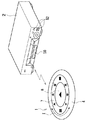
図1は遠隔操作装置で機器を操作する例を示す斜視図、図2は遠隔操作装置の斜視図、図3は遠隔操作装置の平面図、図4は遠隔操作装置の分解斜視図、図5は遠隔操作装置に設けられた各表示装置の配置番号を示す図、図6は遠隔操作装置を片手に持って操作する例を示す斜視図、図7は遠隔操作装置及び機器の概略構成を示すブロック図である。
【0013】
本実施の形態の遠隔操作装置1は、図1及び図6に示すように、例えばDVDプレイヤーなどの機器2を遠隔操作するためのリモートコントロール装置であり、手の平に包み込むようにして片手3で操作し得るハンディータイプのコントローラである。この遠隔操作装置1は、図2〜図4に示すように、コントローラ本体4と、このコントローラ本体4に取り付けられた複数個の表示装置5a〜5qと、各表示装置5a〜5qの下に配置された入力決定部である各種操作スイッチ6a〜6qと、所定間隔を置いて円環状に配置された表示装置5b〜5qの上に回転可能に配置された透明なシャトルリング7と、円環状に配置された表示装置5b〜5qのほぼ中央に配置された表示装置5aの上に配置された透明なセンターボタン8とを有している。
【0014】
コントローラ本体4は、図2及び図6に示すように、卵を縦に切ったような形状をしており、その切り口側に操作スイッチ6a〜6q、表示装置5a〜5q、シャトルリング7及びセンターボタン8を取り付けるための円形状をなす取付凹部9(図4参照)を有している。この取付凹部9の底部には、図7に示すように、機器2との間で信号のやりとりをする送受信部10と、機器2に応じた操作ボタンを表示装置5a〜5qに表示する画像データを記憶しておくメモリ11と、表示装置5a〜5q、送受信部10、メモリ11などを制御する制御部であるCPU12と、図示しない電源などが設けられている。
【0015】
また、コントローラ本体4は、手に握ったときに弾力性があり且つ柔軟でソフトな感触が得られるような材質で形成することが好ましい。もちろん、コントローラ本体4は、硬質なプラスチック材料で形成してもよい。
【0016】
表示装置5a〜5qは、所定間隔を置いて円環状に配置されると共に、その環状に配置された中央部にも配置されている。例えば、16個の表示装置5b〜5qが円環状に配置され、1つの表示装置5aが環状の中央に配置される。これら表示装置5a〜5qは、CPU12によって何れも独立して個々に駆動表示される。表示装置5a〜5qとしては、例えば液晶表示装置が使用される。
【0017】
前記表示装置5a〜5qには、例えば図5に示すように、その配置位置に応じたディスプレイ番号が割り当てられている。中央の表示装置5aは、「00」なるディスプレイ番号が割り当てられ、円環状に配置された表示装置5b〜5qは、図面に向かって一番上から時計回りにそれぞれ「01」、「02」、「03」〜「16」なる番号が割り当てられている。
【0018】
中央に配置された表示装置5aには、例えば機器2の種類や機器2を選択する画像や文字などが表示される。一例を挙げると、DVDプレーヤであれば「DVD」の文字、BSテレビチューナであれば「BS TV」の文字、ビデオテープレコーダであれば「VIDEO」の文字、インターネット接続を可能とする携帯電話端末装置であれば携帯端末装置の画像が表示される。機器2を選択する表示としては、例えば「SOURCE Select」なる文字が表示される。もちろん、これらは一例であり、この表示装置5aには、機器2の種類や機器2を選択する画像や文字の他に、各種機器2の操作モードを表す画像や文字も表示される。
【0019】
円環状に配置された表示装置5b〜5qには、例えば機器2の操作モードを表す画像や文字などが表示される。一例を挙げると、BSテレビチューナであれば、チャンネルを表す「1、2、3・・・12」なる数字、DVDプレーヤであれば、早送り、巻き戻し、停止、一時停止などを表す画像が表示される。この他、この表示装置5b〜5qには、機器2の種類を表示する画像や文字も表示される。
【0020】
操作スイッチ6a〜6qは、図4に示すように、前記各表示装置5a〜5qの下にそれぞれ配置されている。これら操作スイッチ6a〜6qは、後述するシャトルリング7やセンターボタン8を指で押したときにスイッチがオン・オフする。
【0021】
シャトルリング7は、図2及び図3に示すように、円環状の透明リングであり、前記円環状に配置された表示装置5b〜5qの上に配置されている。そして、このシャトルリング7は、図3中矢印Iで示すように、コントローラ本体4に対して回転自在とされている。シャトルリング7は、透明であることから、その下に配置された表示装置5b〜5qに表示される画像や文字などが前記シャトルリング7を介して目視により見ることができる。また、このシャトルリング7を右回転又は左回転させると、例えばビデオテープレコーダ、CDプレイヤー、DVDプレイヤーなどの機器2を選択するモードに切り替わり、そのモードに応じた画像や文字が表示装置5a〜5qに表示される。
【0022】
このように、透明なシャトルリング7の下に表示装置5b〜5qを配置したことにより、例えば図8(A)中矢印IIに示すように、シャトルリング7を右回転させた場合でも、図8(B)に示すようにシャトルリング7の下に配置された表示装置5b〜5qに表示された操作ボタン(操作ボタンとして画像表示される)の配置が変化することがない。但し、シャトルリング7の表面に表示装置5b〜5qを配置した場合は、図9(A)の状態から図9(B)に示すように、シャトルリング7の回転によって操作ボタンの向きが変わってしまうため、操作し難くなる。図8の表示例では、各表示装置5b〜5qに表示される操作ボタンを常に同じ表示装置5b〜5qに表示したが、図10(A)、(B)に示すように、シャトルリング7の回転に合わせて操作ボタンの表示位置を回転させるようにしてもよい。この場合は、操作ボタンの向きは変わらないため、操作に支障を来すことはない。
【0023】
また、シャトルリング7は、例えば円環状に配置された表示装置5b〜5qの配置間隔に応じてそれぞれの表示装置5a〜5qが設けられる位置で一旦停止するように回転可能となっており、操作する者にクリック感を与えるような構成となっている。もちろん、単に途中で引っ掛かることなくスムーズにシャトルリング7が回転可能となっていてもよい。
【0024】
また、シャトルリング7を回転させると、コントローラ本体4に設けられた回転移動量検出部66がこのシャトルリング7の回転を検出し、そのシャトルリング7の回転移動量に応じて前記表示装置5a〜5qに表示される表示内容を切り換える。または、回転移動量検出部66がシャトルリング7の回転を検出すると、そのシャトルリング7の回転移動量に応じて円環状に配置された表示装置5b〜5qで表示された表示内容の一部を、中央の表示装置5aに切り換えて表示する。
【0025】
なお、シャトルリング7は、硬質の透明なプラスチックであっても良いが、弾力性のある柔らかい透明な樹脂成形体であってもよい。特に、シャトルリング7を柔軟な樹脂成形体で形成すれば、後述する操作スイッチ6a〜6qを押し易くなる。
【0026】
センターボタン8は、図3及び図4に示すように、円盤状の透明ボタンであり、中央に配置された表示装置5aの上に配置されている。このセンターボタン8は、シャトルリング7のセンター孔13に臨んで設けられ、当該シャトルリング7とは異なり回転不可能にコントローラ本体4に取り付けられている。かかるセンターボタン8もシャトルリング7と同様に、硬質の透明なプラスチック又は弾力性のある柔らかい透明な樹脂成形体で形成される。センターボタン8を柔軟な樹脂成形体で形成すれば、センターボタン8を押し易くなる。
【0027】
送受信部10は、遠隔操作装置1と機器2との間の信号のやり取りを一方向又は双方向で通信可能となっている。例えば、コントローラ本体4から機器2への一方向通信の場合には、各表示装置5a〜5qに表示された操作ボタンを押したことにより出力される遠隔操作信号が、遠隔操作装置1の送受信部10から機器2に送られる。双方向通信の場合は、各表示装置5a〜5qにどの画像を割り当てるかを決めるための表示画像番号(ディスプレイ番号)などを有した画像表示配置データ(キーアサイン用のデータ)や機器2のメモリー53(図7参照)に記憶されている画像データが、前記機器2から遠隔操作装置1の送受信部10に送られる一方で、各表示装置5a〜5qに表示された操作ボタンを押したことにより出力される遠隔操作信号が、遠隔操作装置1の送受信部10から機器2に送られる。なお、これら遠隔操作装置1と機器2との間で送受信される機能設定用のデータ(画像データと、この画像データを表示装置上に表示するための位置指定情報)については、後に詳述する。
【0028】
メモリ11には、機器2の種類を表示する画像や文字、または、機器2に応じた操作ボタンや文字などの画像データが記憶されている。このメモリ11に記憶されている画像や文字についての具体例については後述する。
【0029】
このように構成された遠隔操作装置1では、操作する機器2に応じてシャトルリング7及びセンターボタン8の下に配置された表示装置5a〜5qに表示される操作ボタンなどの表示内容が変化する。例えば、BSテレビチューナであれば、図11に示すように、センターボタン8には「ENTER BS TV」なる文字が表示されると共に、シャトルリング7には上下左右方向の矢印ボタン14、15、16、17が表示される。DVDチューナであれば、図12に示すように、センターボタン8には「DVD」なる文字及び再生ボタン18が表示されると共に、シャトルリング7には図面に向かって一番上から時計回りにそれぞれ一時停止ボタン19、次のチャプターボタン20、早送りボタン21、スロー再生ボタン22、停止ボタン23、スロー逆戻し再生ボタン24、巻き戻しボタン25、前のチャプターボタン26が表示される。
【0030】
テレビチューナであれば、図13に示すように、センターボタン8には「ENTER TV」なる文字が表示されると共に、シャトルリング7には図面に向かって一番上から時計回りにそれぞれ「volume」なる文字及び音量を上げるプラスボタン27、「channel」なる文字及びチャンネルを昇順で選択するプラスボタン28、「volume」なる文字及び音量を下げるマイナスボタン29、「channel」なる文字及びチャンネルを降順で選択するマイナスボタン30が表示されている。
【0031】
BSテレビチューナであれば、図14に示すように、センターボタン8には「ENTER BS TV」なる文字が表示されると共に、シャトルリング7には図面に向かって一番上から12チャンネルボタン31、1チャンネルボタン32、2チャンネルボタン33、3チャンネルボタン34、4チャンネルボタン35、5チャンネルボタン36、6チャンネルボタン37、7チャンネルボタン38、8チャンネルボタン39、9チャンネルボタン40、10チャンネルボタン41、11チャンネルボタン42が表示されている。
【0032】
携帯電話端末装置であれば、図15に示すように、センターボタン8には携帯電話機をモチーフにした携帯電話ボタン43、シャトルリング7には図面に向かって一番上から時計回りにそれぞれ上操作ボタン44、右操作ボタン45、下操作ボタン46、左操作ボタン47が表示されている。
【0033】
[機器の構成]
次に、機器2の構成について簡単に説明する。図7には、DVDプレイヤーの概略的なブロック図を示す。DVDプレイヤーは、トラッキングサーボやフォーカスサーボなどのサーボ回路48と、ビデオ信号やオーディオ信号の信号処理回路49と、液晶ディスプレイ50(図1参照)に各種情報を表示する表示駆動回路51と、各種操作スイッチ52(図1参照)と、メモリ53と、送受信部54と、これらを制御するCPU55とを有している。
【0034】
[遠隔操作装置による機器の操作例]
図16には、各種ある機器2の中から操作する機器2を選択し、遠隔操作装置1の表示装置5a〜5qに画像が表示されるまでのフローチャートを示す。始めに、ユーザは、ステップS1の処理として、操作する(使用する)機器2を選択する。ここでは、テレビチューナ、ビデオテープレコーダ、DVDプレーヤ、家庭内ネットワークやインターネットなどのネットワークに接続する機器の中から選択する。すなわち、図17に示すように、シャトルリング7に浮かび上がった機器選択用の操作ボタン56、57、58、59を押して決定する。
【0035】
図17の例では、ディスプレイ番号「00」の表示装置5aには、「SOURCE Select」なる文字、ディスプレイ番号「01」の表示装置5bには、「TV」なる文字、ディスプレイ番号「05」の表示装置5fには、「DVD」なる文字、ディスプレイ番号「09」の表示装置5jには、「VIDEO」なる文字、ディスプレイ番号「13」の表示装置5nには、「INTERNET」なる文字が表示されている。この中から使用する機器2を選択して、その文字が表示されている部分(操作ボタン56、57、58、59)を押す。この例では、シャトルリング7が各種機器2のダイレクトボタンとして機能する。
【0036】
この他、図18に示すように、シャトルリング7を回転させて目的の機器2を選択し、中央のセンターボタン8を押し込んで使用する機器2を決定するようにしてもよい。この例では、シャトルリング7を回転させると、ディスプレイ番号「00」の表示装置5aに「DVD」なる文字が表示された図18(A)の状態から、「BS TV」なる文字が表示された図18(B)の状態になる。この中から使用する機器2を選択して、その文字が表示されているセンターボタン8を押す。DVDプレイヤーを使用する場合は、シャトルリング7を回転させてセンターボタン8に「DVD」なる文字が浮かび上がったときに、このセンターボタン8を押す。
【0037】
機器2を選択する選択ボタンが押されると、CPU12は、送受信部10から機器選択信号を使用する機器2に対して送信する。ここで、機器2の主電源がオフになっている場合には、自動的に主電源のスイッチがオンになる。次に、ステップS2の処理において、CPU12は、使用する機器2に対して各表示装置5a〜5qに割り当てる画像などの位置指定情報である画像表示配置データの送信を要求する。
【0038】
画像表示配置データとしては、例えば図19に示すように、2桁の数字からなるディスプレイ番号(図5で示す表示装置5a〜5qのディスプレイ配置番号)と、そのディスプレイ番号に対応する3桁の数字で表される画像表示番号である。この画像表示配置データは、機器2のメモリ53に記憶されている。
【0039】
例えばディスプレイ番号「00」の表示装置5aには画像表示番号「037」の画像(この画像については図20を参照して後述する)、ディスプレイ番号「01」の表示装置5bには画像表示番号「030」の画像、ディスプレイ番号「02」の表示装置5cには画像表示番号「000」の画像、ディスプレイ番号「03」の表示装置5dには画像表示番号「034」の画像、ディスプレイ番号「04」の表示装置5eには画像表示番号「000」の画像、ディスプレイ番号「05」の表示装置5fには画像表示番号「036」の画像、ディスプレイ番号「06」の表示装置5gには画像表示番号「000」の画像、ディスプレイ番号「07」の表示装置5hには画像表示番号「032」の画像、ディスプレイ番号「08」の表示装置5iには画像表示番号「000」の画像がそれぞれ対応する。
【0040】
同様に、ディスプレイ番号「09」の表示装置5jには画像表示番号「029」の画像、ディスプレイ番号「10」の表示装置5kには画像表示番号「000」の画像、ディスプレイ番号「11」の表示装置5lには画像表示番号「031」の画像、ディスプレイ番号「12」の表示装置5mには画像表示番号「000」の画像、ディスプレイ番号「13」の表示装置5nには画像表示番号「035」の画像、ディスプレイ番号「14」の表示装置5oには画像表示番号「000」の画像、ディスプレイ番号「15」の表示装置5pには画像表示番号「033」の画像、ディスプレイ番号「16」の表示装置5qには画像表示番号「000」の画像がそれぞれ対応する。
【0041】
そして、遠隔操作装置1のCPU12は、図19に示した画像表示配置データの表示データリストを受信すると、ステップS4の処理に進み、受信が無かった場合は、ステップS2の処理に戻る。ステップS4の処理では、遠隔操作装置1に送られてきた表示データリストを元に、CPU12は、表示装置5a〜5qに表示する画像を前記遠隔操作装置1のメモリ11から読み出す。
【0042】
画像データとしては、例えば図20に示すように、3桁の数字からなる画像表示番号と、その画像表示番号に対応する画像(数字、文字、記号など)である。例えば、画像表示番号「000」には表示されるものは無く、画像表示番号「001」〜「012」にはトラック番号又はチャンネル番号を表す「1〜12」の数字、画像表示番号「013」には「ENTER TV」の文字、画像表示番号「014」には上方向キーを表す「上向きの矢印」、画像表示番号「015」には下方向キーを表す「下向きの矢印」、画像表示番号「016」には左方向キーを表す「左向きの矢印」、画像表示番号「017」には右方向キーを表す「右向きの矢印」、画像表示番号「018」には「ENTER BS TV」の文字、画像表示番号「019」には上方向キーを表す「上向き三角形」の記号、画像表示番号「020」には下方向キーを表す「下向き三角形」の記号、画像表示番号「021」には左方向キーを表す「左向き三角形」の記号、画像表示番号「022」には右方向キーを表す「右向き三角形」の記号がそれぞれ割り当てられている。
【0043】
同様に、画像表示番号「023」には「携帯電話機」の記号、画像表示番号「024」にはチャンネル選択用の「channel」の文字及び「プラス」の記号、画像表示番号「025」にはチャンネル選択用の「channel」の文字及び「マイナス」の記号、画像表示番号「026」には音量調整用の「volume」の文字及び「プラス」の記号、画像表示番号「027」には音量調整用の「volume」の文字及び「マイナス」の記号、画像表示番号「028」には「ENTER」の文字及び「プラスとマイナス」の記号、画像表示番号「029」には停止を意味する「四角形」の記号、画像表示番号「030」には一時停止を意味する「縦2本線」の記号、画像表示番号「031」にはスロー逆戻し再生を意味する「縦にスリットが入った左向き三角形」の記号、画像表示番号「032」にはスロー再生を意味する「縦にスリットが入った右向き三角形」の記号、画像表示番号「033」には前キャプチャーを意味する「縦1本線と2つの左向き三角形」の記号、画像表示番号「034」には次キャプチャーを意味する「縦線1本と2つの右向き三角形」の記号、画像表示番号「035」には巻き戻しを意味する「2つの左向き三角形」の記号、画像表示番号「036」には早送りを意味する「2つの右向き三角形」の記号、画像表示番号「037」には「DVD」の文字及び再生を意味する「右向き三角形」の記号、画像表示番号「038」には取出しの文字及び「横1本線と上向き三角形」の記号、画像表示番号「039」には「録画」の文字及び録画を意味する「丸形状」の記号がそれぞれ割り当てられている。
【0044】
このように、遠隔操作装置1のメモリ11には、例えばDVDプレーヤ、CDプレーヤまたはインターネットに接続可能な携帯電話機などの如く想定される全ての機器2で操作する操作ボタンなどの表示データが記憶されている。これら数字、文字、記号などからなる画像データは、前記機器2から送られてきた画像表示配置データを元に、メモリ11から対応する画像データが読み出される。そして、その画像表示配置データに挙げられた画像データがメモリ11から全て読み出されると、CPU12は、ステップS6の処理でそれぞれの表示装置5a〜5qにその画像を表示する。画像表示配置データの表示データリストに挙げられた全ての画像データがメモリ11から読み出されていない場合は、CPU12は、ステップS4の処理を繰り返す。
【0045】
図19に示す画像表示配置データのリストに基づく各表示装置5a〜5qへの画像データの読み出しは次の通りである。ディスプレイ番号「00」の表示装置5aには画像表示番号「037」のDVD再生用の操作ボタンが表示され、ディスプレイ番号「01」の表示装置5bには画像表示番号「030」の一時停止ボタンが表示され、ディスプレイ番号「02」の表示装置5cには画像表示番号「000」に対応して何も表示されず、ディスプレイ番号「03」の表示装置5dには画像表示番号「034」の次キャプチャーボタンが表示され、ディスプレイ番号「04」の表示装置5eには画像表示番号「000」に対応して何も表示されず、ディスプレイ番号「05」の表示装置5fには画像表示番号「036」の早送りボタンが表示され、ディスプレイ番号「06」の表示装置5gには画像表示番号「000」に対応して何も表示されず、ディスプレイ番号「07」の表示装置5hには画像表示番号「032」のスロー再生ボタンが表示され、ディスプレイ番号「08」の表示装置5iには画像表示番号「000」に対応して何も表示されない。
【0046】
同様に、ディスプレイ番号「09」の表示装置5jには画像表示番号「029」の停止ボタンが表示され、ディスプレイ番号「10」の表示装置5kには画像表示番号「000」に対応して何も表示されず、ディスプレイ番号「11」の表示装置5lには画像表示番号「031」のスロー逆戻し再生ボタンが表示され、ディスプレイ番号「12」の表示装置5mには画像表示番号「000」に対応して何も表示されず、ディスプレイ番号「13」の表示装置5nには画像表示番号「035」の巻き戻しボタンが表示され、ディスプレイ番号「14」の表示装置5oには画像表示番号「000」に対応して何も表示されず、ディスプレイ番号「15」の表示装置5pには画像表示番号「033」の前キャプチャーボタンが表示され、ディスプレイ番号「16」の表示装置5qには画像表示番号「000」に対応して何も表示されない。
【0047】
[本実施の形態のまとめ]
このように、本実施の形態の遠隔操作装置1では、各表示装置5a〜5qに画像を割り当てる画像表示番号を列挙した画像表示配置データを機器2から受信し、その受信したデータリストを元に、遠隔操作装置1のメモリ11からそのデータリストに応じた画像データが読み出されて各表示装置5a〜5qに操作ボタンとしてシャトルリング7及びセンターボタン8に表示しているため、操作する機器2の持つ全ての操作ボタンをこのシャトルリング7及びセンターボタン8に表示させることができ、ユーザは各操作ボタンがどの操作に対応しているかを意識することなく操作することができる。
【0048】
また、この遠隔操作装置1では、操作する機器2のみの操作ボタンがシャトルリング7及びセンターボタン8に表示されるため、1つのボタンに複数の各機器毎の各種操作を割り当てる必要がなく、操作ボタンの数が増えることを抑え、少ない操作ボタンで効率良く操作することができる。
【0049】
また、本実施の形態の遠隔操作装置1では、機器2に対して双方向通信であるため、ビデオテープレコーダのように録画と再生の如き同じようなソースであっても、それぞれの特徴に応じて表示装置5a〜5qに表示する表示内容を変えることができる。
【0050】
また、本実施の形態の遠隔操作装置1では、DVDプレイヤーを操作する例としたが、テレビチューナ、ビデオテープレコーダ、CDプレーヤ、家庭内ネットワークやインターネットなどのネットワークに接続する機器2を操作する場合も同様に、その機器2の操作ボタンのみをシャトルリング7及びセンターボタン8に表示させることができ、誤った操作を防止することができる。
【0051】
また、本実施の形態の遠隔操作装置1では、ビデオゲーム機やネットワークに接続する機器の操作ボタンのみをシャトルリング7及びセンターボタン8に表示するだけではなく、そのビデオゲーム機やネットワークに接続する機器で実行されるアプリケーションプログラムを操作するための操作ボタンも、このシャトルリング7及びセンターボタン8に表示させることもできる。
【0052】
[その他の実施形態]
上述の実施の形態では、遠隔操作装置1からの送信要求に応じて機器2から画像表示配置データまたは操作ボタンの画像データを遠隔操作装置1に送信したが、これらのデータに加えて音声データを隔操作装置1に送信するようにしてもよい。音声データを遠隔操作装置1に送信すれば、例えば操作ボタンを押したときに、音声によってボタンが選択されたことを操作する者に認識させることができ、より一層の付加価値を高めることができる。
【0053】
また、本実施の形態では、機器2から遠隔操作装置1に対して送信する機能設定用のデータの一つとして、遠隔操作装置1を持った手に振動を与えるフォースフィードバック用のデータを利用し、このフォースフィードバック用のデータを前記遠隔操作装置1に送信するようにしてもよい。この場合は、コントローラ本体4には、前記フォースフィードバック用のデータを受信して前記コントローラ本体4を振動させる振動機構などの応答手段を設けておく必要がある。
【0054】
このように構成すれば、例えば操作ボタンを押したときに、コントローラ本体4に設けた振動機構が作動して当該コントローラ本体4が振動し、その振動により前記操作ボタンの入力が決定したことを、遠隔操作装置1を操作する者に知らしめることができる。
【0055】
また、上述の実施の形態では、遠隔操作装置1と機器2とが双方向に通信可能な例であるが、遠隔操作装置1から機器2への一方向への通信であってもよい。一方向通信の場合は、双方向通信とは異なり前記した機器2から各表示装置5a〜5qにどの画像を表示するかを割り当てる画像表示配置データ(図19参照)を送る必要はない。
【0056】
すなわち、一方向通信による遠隔操作装置1では、操作する機器2を選択したときに、その機器2に備わる操作ボタン又はその機器2で実行されるアプリケーションプログラムにより表示される各種操作ボタンを表す画像データと、その画像データを何処の位置に配置させた表示装置5a〜5qで表示させるかを指定する画像表示配置データとが遠隔操作装置1に設けられたメモリ11から読み出され、その画像表示配置データを元に読み出された画像データが、指定された表示装置5a〜5qでそれぞれ表示される。なお、メモリ11から読み出される画像は、画像表示配置データによって、予めどの位置に配置された表示装置5a〜5qで表示されるかが一意に決められている。
【0057】
また、上述の実施の形態では、遠隔操作装置1で操作する全ての機器2の操作ボタンを表す画像データ(図20に示すデータ)を遠隔操作装置1のメモリ11に記憶したが、その画像データを機器2に記憶しておいてもよい。
【0058】
また、図21には、それぞれの画像データを各表示装置5a〜5qに割り当てるための画像表示配置データのリストを示す。ディスプレイ番号「00」の表示装置5aには「DVD」の文字及び再生を意味する「右向き三角形」の記号、ディスプレイ番号「01」の表示装置5bには一時停止を意味する「縦2本線」の記号、ディスプレイ番号「02」の表示装置5cには表示無し、ディスプレイ番号「03」の表示装置5dには次キャプチャーを意味する「縦線1本と2つの右向き三角形」の記号、ディスプレイ番号「04」の表示装置5eには表示無し、ディスプレイ番号「05」の表示装置5fには早送りを意味する「2つの右向き三角形」の記号、ディスプレイ番号「06」の表示装置5gには表示無し、ディスプレイ番号「07」の表示装置5hにはスロー再生を意味する「縦にスリットが入った右向き三角形」の記号、ディスプレイ番号「08」の表示装置5iには表示無しがそれぞれ割り当てられている。
【0059】
同様に、ディスプレイ番号「09」の表示装置5jには停止を意味する「四角形」の記号、ディスプレイ番号「10」の表示装置5kには表示無し、ディスプレイ番号「11」の表示装置5lにはスロー逆戻し再生を意味する「縦にスリットが入った左向き三角形」の記号、ディスプレイ番号「12」の表示装置5mには表示無し、ディスプレイ番号「13」の表示装置5nには巻き戻しを意味する「2つの左向き三角形」の記号、ディスプレイ番号「14」の表示装置5oには表示無し、ディスプレイ番号「15」の表示装置5pには前キャプチャーを意味する「縦1本線と2つの左向き三角形」の記号、ディスプレイ番号「16」の表示装置5qには表示無しがそれぞれ割り当てられている。
【0060】
このように、それぞれの画像データを各表示装置5a〜5qに割り当てるための画像表示配置データを機器2に持たせておくことで、それぞれの機器2に応じた操作ボタンの割り当てを自由にカスタマイズすることができる。つまり、あるメーカのビデオテープレコーダでは、他のメーカでは無い2倍速再生機能を有している場合、その2倍速再生ボタンをダイレクトボタンとして操作ボタンに割り当て、前記2倍速再生ボタンを表す画像を表示装置5a〜5qに表示することができる。要するに、特殊な機能を備えた機器2の場合でも、その特殊な機能を操作する操作ボタンを遠隔操作装置1に割り当てることができる。
【0061】
また、それぞれの画像データを各表示装置5a〜5qに割り当てるための画像表示配置データを機器2に持たせるのではなく、図22に示すように、遠隔操作装置1や機器2を例えばインターネット60に接続し、そのインターネット60に接続されたあるサーバ61の記憶装置62に画像表示配置データを記憶させて置き、インターネット60を介して前記画像表示配置データを遠隔操作装置1や機器2にダウンロードしてもよい。
【0062】
このように、画像表示配置データをインターネット60を介してダウンロードすれば、遠隔操作装置1や機器2にデータを持つ場合に比べて、より多くの種類の画像を表示できると共に画像の交換を簡単に行うことができる。また、操作ボタンなどの画像データのみを、インターネット60を介して遠隔操作装置1や機器2にダウンロードするようにしてもよい。
【0063】
上記の例は、インターネット60を介した例であるが、この他に家庭内ネットワークなどのネットワークを介して画像データや画像表示配置データを遠隔操作装置1や機器2にダウンロードしてもよい。
【0064】
また、上述の実施の形態の遠隔操作装置1は、卵を縦に切ったような形状のコントローラ本体4としたが、この形状に制限されることはなく、種々の形態が採用できる。例えば、図23に示すように、コントローラ本体63の形状を縦長に円形を引き延ばした形状とし、その一端側近傍にシャトルリング7及びセンターボタン8を設けた形態であってもよい。この遠隔操作装置64は、片手に持って操作してもよく、または、机やテーブルの上に置いて使用してもよい。なお、縦長のコントローラ本体63の先端には、送受信部65が設けられている。
【0065】
また、上述の実施の形態の遠隔操作装置1では、各表示装置5a〜5qの下に操作スイッチ6a〜6qを配置したが、これら表示装置5a〜5qと操作スイッチ6a〜6qとを別々に配置するようにしても構わない。例えば、図24に示すように、表示装置5b、5f、5j、5nをシャトルリング7の外側に配置してもよい。
【0066】
【発明の効果】
本発明によれば、遠隔操作装置に設けられた表示部に、遠隔操作する機器が有する機能を実行するための各種操作ボタンの画像を割り当てて表示させることができると共に、ユーザは各操作ボタンがどの操作に対応しているかを意識することなく操作ボタンを操作することができ、また、1つのボタンに複数の操作を割り当てる必要がなく、操作ボタンの数の増加を抑えることができる。
【図面の簡単な説明】
【図1】本実施の形態の遠隔操作装置によって機器を操作する例を示す斜視図である。
【図2】本実施の形態の遠隔操作装置の斜視図である。
【図3】本実施の形態の遠隔操作装置の平面図である。
【図4】本実施の形態の遠隔操作装置の分解斜視図である。
【図5】本実施の形態の遠隔操作装置に設けられた各表示装置の配置番号を示す図である。
【図6】本実施の形態の遠隔操作装置を片手に持って操作する例を示す斜視図である。
【図7】遠隔操作装置及び機器の概略構成を示すブロック図である。
【図8】シャトルリングを回転しても表示装置に表示された操作ボタンの配置が変化しないことを示す図である。
【図9】表示装置をシャトルリングの表面に配置した例であり、シャトルリングの回転により操作ボタンの向きが変わってしまうことを示す図である。
【図10】シャトルリングを回転しても表示装置に表示された操作ボタンの配置が変化しないことを示す図である。
【図11】BSテレビチューナの操作ボタンを表示した例を示す図である。
【図12】DVDチューナの操作ボタンを表示した例を示す図である。
【図13】テレビチューナの操作ボタンを表示した例を示す図である。
【図14】BSテレビチューナの操作ボタンを表示した例を示す図である。
【図15】携帯電話端末装置の操作ボタンを表示した例を示す図である。
【図16】機器の選択から遠隔操作装置の表示装置に画像が表示されるまでの流れを示すフローチャートである。
【図17】シャトルリングに機器選択用の操作ボタンが表示された状態を示す図である。
【図18】シャトルリングを回転させて目的の機器を選択する状態を示す図である。
【図19】機器のメモリに記憶された画像表示配置データのリストを示すもので、遠隔操作装置に送信するディスプレイ番号と画像表示番号からなる画像表示配置データを示す図である。
【図20】遠隔操作装置のメモリに記憶された画像データのリストを示すもので、画像表示番号と、その画像表示番号に対応する画像を示す図である。
【図21】機器のメモリに記憶された表示画像の画像表示配置データのリストを示すもので、各表示装置に割り当てる画像を示す図である。
【図22】インターネットから画像表示配置データを遠隔操作装置や機器にダウンロードする例を示す図である。
【図23】コントローラ本体の形状を縦長に円形を引き延ばした形状とした例の遠隔操作装置の他の実施の形態を示す図である。
【図24】表示装置をシャトルリングの外側に配置した例を示す他の実施の形態の図である。
【符号の説明】
1…遠隔操作装置、2…機器、4…コントローラ本体、5a〜5q…表示装置、6a〜6q…操作スイッチ、7…シャトルリング、8…センターボタン、10…送受信部、11…メモリ、53…メモリ、54…送受信部、60…インターネット、61…サーバ[0001]
The present invention relates to a remote operation device, a remote operation system, an image display method, an image display program for causing a computer to execute, and a computer for causing the computer to remotely operate devices such as a DVD player, a video tape recorder, and a TV tuner, for example. The present invention relates to a computer-readable recording medium on which the image display program is recorded.
[0002]
[Prior art]
For example, a remote control device that remotely controls a television receiver or a video tape recorder from a remote location or a game controller that operates a video game machine or the like has a one-way communication function. Are provided with various operation buttons corresponding to these devices.
[0003]
Usually, for these operation buttons, the operation to be operated is uniquely determined. For example, in the case of a playback button, only the function of playing is assigned to this playback button. In addition, there are some in which a plurality of functions (operations) are assigned to one operation button. For example, some application programs such as games can freely change key assignments, and therefore, a number of operations can be performed with one operation button.
[0004]
[Problems to be solved by the invention]
However, since only the characters and symbols corresponding to one operation are displayed on the operation buttons, the user must always be aware of which operation each operation button corresponds to. For this reason, the user can be confused.
[0005]
On the other hand, there is a method of increasing the number of operation buttons by reducing the number of operations assigned to one operation button. However, if it does so, an operation button will increase and it will become difficult to operate.
[0006]
The present invention enables two-way communication, changes the display of each operation button according to the device or application program to be operated, allows the user to easily operate each operation button, and the number of operation buttons is A remote operation device, an electric device, a remote operation system, an image display method, an image display program for causing a computer to execute, and an image display program for causing a computer to execute, which can be controlled with a small number of operation buttons while suppressing an increase. An object is to provide a recorded computer-readable recording medium.
[0007]
[Means for Solving the Problems]
The remote control device of the present invention includes a transmission / reception unit that transmits / receives signals to / from a remotely operated device. The remote operation device of the present invention includes a display unit that displays an operation button for executing a function of the device as an image, and an input determination unit that determines an input of the operation button.
[0008]
The image data defined in the present invention is a concept including characters such as numerals and English letters in addition to images such as icons, marks and illustrations.
[0009]
DETAILED DESCRIPTION OF THE INVENTION
Hereinafter, specific embodiments to which the present invention is applied will be described in detail with reference to the drawings.
[0010]
This embodiment is a television tuner such as terrestrial, BS (broadcasting satellite), CS (communication satellite), a video tape recorder or video recorder for storing data on a magnetic tape or a hard disk, a CD player, a DVD player, a video game. The present invention is applied to a remote control device (remote control device) that remotely controls various electrical devices such as mobile phones and mobile phone terminals that can be connected to the Internet.
[0011]
The present invention includes a television tuner, a video tape recorder, a CD player, a DVD player, a video game machine, a device connected to a network such as a home network or the Internet, etc. as one piece of hardware, or individual devices thereof. Can be operated with one remote control device.
[0012]
[Configuration of remote control device]
1 is a perspective view showing an example of operating a device with a remote control device, FIG. 2 is a perspective view of the remote control device, FIG. 3 is a plan view of the remote control device, FIG. 4 is an exploded perspective view of the remote control device, FIG. Is a diagram showing an arrangement number of each display device provided in the remote control device, FIG. 6 is a perspective view showing an example of operating the remote control device with one hand, and FIG. 7 shows a schematic configuration of the remote control device and equipment. It is a block diagram.
[0013]
As shown in FIGS. 1 and 6, the
[0014]
As shown in FIGS. 2 and 6, the controller
[0015]
The
[0016]
The
[0017]
For example, as shown in FIG. 5, display numbers corresponding to the arrangement positions are assigned to the
[0018]
On the
[0019]
For example, images and characters representing the operation mode of the
[0020]
As shown in FIG. 4, the operation switches 6 a to 6 q are arranged below the
[0021]
As shown in FIGS. 2 and 3, the
[0022]
Since the
[0023]
Further, the
[0024]
Further, when the
[0025]
The
[0026]
As shown in FIGS. 3 and 4, the
[0027]
The transmission /
[0028]
The
[0029]
In the
[0030]
In the case of a TV tuner, as shown in FIG. 13, the characters “ENTER TV” are displayed on the
[0031]
In the case of the BS TV tuner, as shown in FIG. 14, the characters “ENTER BS TV” are displayed on the
[0032]
In the case of a mobile phone terminal device, as shown in FIG. 15, the
[0033]
[Device configuration]
Next, the configuration of the
[0034]
[Example of device operation by remote control device]
FIG. 16 shows a flowchart for selecting a
[0035]
In the example of FIG. 17, the
[0036]
In addition, as shown in FIG. 18, the
[0037]
When a selection button for selecting the
[0038]
As the image display arrangement data, for example, as shown in FIG. 19, a display number consisting of two digits (display arrangement numbers of the
[0039]
For example, the
[0040]
Similarly, the
[0041]
Then, when receiving the display data list of the image display arrangement data shown in FIG. 19, the
[0042]
As the image data, for example, as shown in FIG. 20, there are an image display number consisting of a three-digit number and an image (number, character, symbol, etc.) corresponding to the image display number. For example, there is nothing to be displayed in the image display number “000”, the image display numbers “001” to “012” are numbers “1-12” representing the track number or channel number, and the image display number “013”. Is the character “ENTER TV”, the image display number “014” is the “upward arrow” representing the up key, the image display number “015” is the “down arrow” representing the down key, and the image display number “016” indicates a “left arrow” indicating a left arrow key, “017” indicates a “right arrow” indicating a right key, and “ENTER BS TV” indicates an image display number “018”. The image display number “019” represents the “upward triangle” symbol representing the up key, the image display number “020” represents the “down triangle” symbol representing the down key, and the image display number “021” left Direction key Symbol "left triangle" indicating that the image display number "022" represents the right key symbol "right triangle" are respectively assigned.
[0043]
Similarly, the symbol “mobile phone” is displayed for the image display number “023”, the characters “channel” and “plus” for channel selection are displayed for the image display number “024”, and the symbol “plus” is displayed for the image display number “025”. “Channel” for channel selection and “minus” symbol, “volume” for volume adjustment and “plus” symbol for image display number “026”, volume adjustment for image display number “027” “Volume” and “minus” symbol for image, “ENTER” character and “plus and minus” symbol for image display number “028”, “square” meaning stop for image display number “029” ”, The image display number“ 030 ”,“ vertical two lines ”signifying pause, and the image display number“ 031 ”,“ slip vertically ”meaning slow reverse playback. The symbol “left-pointing triangle with a triangle”, the image display number “032” signifies slow playback, the symbol “right-pointing triangle with a vertical slit”, and the image display number “033” signifies “pre-capture”. The symbol “vertical 1 line and 2 left triangles”, the image display number “034” means the next capture “vertical 1 line and 2 triangles right” and the image display number “035” are rewound. Meaning “two left-pointing triangles” symbol, image display number “036” means “two right-pointing triangles” symbol, and image display number “037” means “DVD” characters and playback. “Right triangle” symbol, image display number “038” means extracted character and “horizontal line and upward triangle” symbol, image display number “039” means “record” character and recording. Symbol "rounded" is assigned, respectively.
[0044]
As described above, the
[0045]
Reading of image data to each of the
[0046]
Similarly, the
[0047]
[Summary of this embodiment]
As described above, in the
[0048]
Further, in this
[0049]
Further, in the
[0050]
In the
[0051]
Further, in the
[0052]
[Other Embodiments]
In the above-described embodiment, the image display arrangement data or the image data of the operation buttons is transmitted from the
[0053]
In the present embodiment, force feedback data that gives vibration to the hand holding the
[0054]
If comprised in this way, when the operation button is pressed, for example, the vibration mechanism provided in the
[0055]
In the above-described embodiment, the
[0056]
That is, in the
[0057]
In the above-described embodiment, image data (data shown in FIG. 20) representing the operation buttons of all the
[0058]
FIG. 21 shows a list of image display arrangement data for assigning the respective image data to the
[0059]
Similarly, the
[0060]
In this way, by assigning the
[0061]
Further, instead of providing the
[0062]
As described above, if the image display arrangement data is downloaded via the
[0063]
The above example is an example via the
[0064]
Moreover, although the
[0065]
In the
[0066]
【The invention's effect】
According to the present invention, it is possible to allocate and display images of various operation buttons for executing the functions of the remotely operated device on the display unit provided in the remote operation device, and the user can select each operation button. The operation buttons can be operated without being aware of which operation is supported, and it is not necessary to assign a plurality of operations to one button, and an increase in the number of operation buttons can be suppressed.
[Brief description of the drawings]
FIG. 1 is a perspective view showing an example in which an apparatus is operated by a remote control device according to an embodiment.
FIG. 2 is a perspective view of a remote control device according to the present embodiment.
FIG. 3 is a plan view of the remote control device according to the present embodiment.
FIG. 4 is an exploded perspective view of the remote control device according to the present embodiment.
FIG. 5 is a diagram showing an arrangement number of each display device provided in the remote control device of the present embodiment.
FIG. 6 is a perspective view showing an example in which the remote control device of the present embodiment is operated with one hand.
FIG. 7 is a block diagram showing a schematic configuration of a remote control device and equipment.
FIG. 8 is a diagram showing that the arrangement of operation buttons displayed on the display device does not change even when the shuttle ring is rotated.
FIG. 9 is an example in which the display device is arranged on the surface of the shuttle ring, and shows that the direction of the operation button is changed by the rotation of the shuttle ring.
FIG. 10 is a diagram showing that the arrangement of operation buttons displayed on the display device does not change even when the shuttle ring is rotated.
FIG. 11 is a diagram showing an example in which operation buttons of a BS television tuner are displayed.
FIG. 12 is a diagram showing an example in which operation buttons of a DVD tuner are displayed.
FIG. 13 is a diagram illustrating an example in which operation buttons of a television tuner are displayed.
FIG. 14 is a diagram showing an example in which operation buttons of a BS television tuner are displayed.
FIG. 15 is a diagram showing an example in which operation buttons of a mobile phone terminal device are displayed.
FIG. 16 is a flowchart showing a flow from selection of a device to display of an image on the display device of the remote control device.
FIG. 17 is a diagram showing a state where operation buttons for device selection are displayed on the shuttle ring.
FIG. 18 is a diagram illustrating a state in which a target device is selected by rotating a shuttle ring.
FIG. 19 shows a list of image display arrangement data stored in the memory of the device, and is a diagram showing image display arrangement data composed of a display number and an image display number transmitted to the remote control device.
FIG. 20 shows a list of image data stored in the memory of the remote control device, and is a diagram showing an image display number and an image corresponding to the image display number.
FIG. 21 shows a list of image display arrangement data of display images stored in the memory of the device, and is a diagram showing an image assigned to each display device.
FIG. 22 is a diagram illustrating an example of downloading image display arrangement data from the Internet to a remote control device or device.
FIG. 23 is a diagram showing another embodiment of the remote control device of an example in which the shape of the controller main body is a vertically elongated shape of a circle.
FIG. 24 is a view of another embodiment showing an example in which the display device is arranged outside the shuttle ring.
[Explanation of symbols]
DESCRIPTION OF
Claims (24)
装置本体と、
前記機器との間で通信を行う通信部と、
前記装置本体に回転自在に支持された回転体と、
前記回転体の回転軸の周囲に配置され該回転体の表面側から視認可能な複数の表示部と、
前記複数の表示部にそれぞれ対応して各表示部の裏面下に配置され、前記複数種類の機器のうち遠隔操作対象となる機器に対応してそれぞれ機能が割り当てられ、前記表示部の表面側からの押圧操作によって押下される複数の操作入力部と、
前記回転体の回転移動量を検出する回転移動量検出部と、
前記遠隔操作対象となる機器の機能に対応付けられた画像データが格納される記憶部と、
前記回転移動量検出部が検出する前記回転体の回転移動量に応じて遠隔操作対象となる機器を決定し、決定した機器に対応付けられた画像データを前記記憶部から読み出して、各操作入力部に割り当てられた機能に対応する画像を当該操作入力部に対応する表示部に表示させると共に、前記操作入力部の押下に応じて当該操作入力部に割り当てられた機能に対応する信号を前記通信部から送信させる制御部とを備えた
ことを特徴とする遠隔操作装置。A remote control device capable of remotely controlling multiple types of devices,
The device body;
A communication unit for communicating with the device;
A rotating body rotatably supported by the apparatus body;
A plurality of display units arranged around the rotation axis of the rotating body and visible from the surface side of the rotating body ;
Corresponding to each of the plurality of display units, it is arranged below the back surface of each display unit, and a function is assigned to each of the plurality of types of devices corresponding to a remote operation target device, from the front side of the display unit A plurality of operation input units pressed by the pressing operation,
A rotational movement amount detection unit for detecting a rotational movement amount of the rotating body;
A storage unit for storing image data associated with the function of the device to be remotely operated;
A device to be remotely operated is determined according to the rotational movement amount of the rotating body detected by the rotational movement amount detection unit, image data associated with the determined device is read from the storage unit, and each operation input An image corresponding to the function assigned to the unit is displayed on the display unit corresponding to the operation input unit, and a signal corresponding to the function assigned to the operation input unit in response to pressing of the operation input unit is transmitted to the communication unit. A remote control device comprising: a control unit for transmitting from the unit.
前記回転体は、透明な板状領域を有し、
前記複数の表示部は、前記回転体の板状領域の裏面側に配置され、
前記操作入力部は、前記板状領域の表面側からの押圧操作によって押下される
ことを特徴とする遠隔操作装置。The remote control device according to claim 1,
The rotating body has a transparent plate-like region,
The plurality of display units are arranged on the back side of the plate-like region of the rotating body,
The operation input unit is pressed by a pressing operation from the surface side of the plate-like region.
前記複数の表示部と前記複数の操作入力部とは、前記装置本体に固定されている
ことを特徴とする遠隔操作装置。The remote control device according to claim 2,
The plurality of display units and the plurality of operation input units are fixed to the apparatus main body.
前記複数の表示部と前記複数の操作入力部とは、前記回転体に固定されている
ことを特徴とする遠隔操作装置。The remote control device according to claim 2,
The remote operation device, wherein the plurality of display units and the plurality of operation input units are fixed to the rotating body.
前記装置本体に固定された第2の表示部を備え、
前記制御部は、前記回転移動量検出部が検出する前記回転体の回転移動量に応じて、前記第2の表示部の表示制御を行う
ことを特徴とする遠隔操作装置。The remote control device according to any one of claims 2 to 4,
A second display unit fixed to the apparatus body;
The remote control device, wherein the control unit performs display control of the second display unit according to a rotational movement amount of the rotating body detected by the rotational movement amount detection unit.
前記制御部は、前記回転移動量検出部が検出する前記回転体の回転移動量に応じて、前記複数の表示部に表示させた表示内容の一部を、前記第2の表示部に切り換えて表示させる
ことを特徴とする遠隔操作装置。The remote control device according to claim 5,
The control unit switches a part of display contents displayed on the plurality of display units to the second display unit according to the rotational movement amount of the rotating body detected by the rotational movement amount detection unit. A remote control device characterized by being displayed.
前記第2の表示部の裏面下に配置され、前記第2の表示部の表面側からの押圧操作によって押下される第2の操作入力部を備え、
前記制御部は、前記複数の表示部に表示させた表示内容の一部を前記第2の表示部に切り換えて表示させた状態で前記第2の操作入力部が押下されたとき、前記切り換えて表示された表示内容の一部に割り当てられた機能に対応する信号を前記通信部から送信させる
ことを特徴とする遠隔操作装置。The remote control device according to claim 6,
A second operation input unit disposed below the back surface of the second display unit and pressed by a pressing operation from the front side of the second display unit;
When the second operation input unit is pressed in a state where a part of the display contents displayed on the plurality of display units is switched to the second display unit and displayed, the control unit performs the switching. A remote operation device, characterized in that a signal corresponding to a function assigned to a part of displayed display content is transmitted from the communication unit.
前記記憶部には、前記複数種類の機器に対応付けられた画像データが格納され、
前記制御部は、前記回転移動量検出部が検出する前記回転体の回転移動量の変化に応じて、前記機器に対応付けられた画像データを前記記憶部から順次読み出して、当該機器を示す画像を前記第2の表示部に順次切り換えて表示させる
ことを特徴とする遠隔操作装置。The remote control device according to claim 5,
The storage unit stores image data associated with the plurality of types of devices,
The control unit sequentially reads out image data associated with the device from the storage unit according to a change in the rotational movement amount of the rotating body detected by the rotational movement amount detection unit, and displays the image indicating the device Are displayed on the second display unit by sequentially switching them.
前記第2の表示部の裏面下に配置され、前記第2の表示部の表面側からの押圧操作によって押下される第2の操作入力部を備え、
前記制御部は、前記機器を示す画像を前記第2の表示部に表示させている状態で前記第2の操作入力部が押下されたとき、当該機器を遠隔操作対象と決定する
ことを特徴とする遠隔操作装置。The remote control device according to claim 8, wherein
A second operation input unit disposed below the back surface of the second display unit and pressed by a pressing operation from the front side of the second display unit;
The control unit determines the device as a remote operation target when the second operation input unit is pressed in a state where an image showing the device is displayed on the second display unit. Remote control device.
前記装置本体に固定された第2の表示部と、
前記第2の表示部の裏面下に配置され、前記第2の表示部の表面側からの押圧操作によって押下される第2の操作入力部とを備え、
前記第2の操作入力部には、前記複数種類の機器のうち遠隔操作対象となる機器に応じて機能が割り当てられ、
前記制御部は、遠隔操作対象として決定した機器に対応付けられた画像データを前記記憶部から読み出して、前記第2の操作入力部に割り当てられた機能に対応する画像を前記第2の表示部に表示させると共に、前記第2の操作入力部の押下に応じて当該第2の操作入力部に割り当てられた機能に対応する信号を前記通信部から送信させる
ことを特徴とする遠隔操作装置。The remote control device according to any one of claims 2 to 4,
A second display unit fixed to the apparatus body;
A second operation input unit disposed below the back surface of the second display unit and pressed by a pressing operation from the front side of the second display unit,
Wherein the second operation input unit, the function according to the device to be remotely operated object among a plurality of types of devices are assigned,
The control unit reads image data associated with a device determined as a remote operation target from the storage unit, and displays an image corresponding to a function assigned to the second operation input unit in the second display unit. And a signal corresponding to a function assigned to the second operation input unit in response to pressing of the second operation input unit is transmitted from the communication unit.
前記複数の表示部が前記回転軸を中心とした円環状に配置されると共に、その円環のほぼ中央に前記第2の表示部が配置されている
ことを特徴とする遠隔操作装置。The remote control device according to any one of claims 5 to 10,
The remote control device, wherein the plurality of display units are arranged in an annular shape centering on the rotation axis, and the second display unit is arranged substantially at the center of the ring.
前記回転体は、透明なリング板形状を有する樹脂成形体であり、円環状に配置された前記複数の表示部の上に配置されている
ことを特徴とする遠隔操作装置。The remote control device according to claim 11,
The said rotary body is a resin molding which has a transparent ring-plate shape, and is arrange | positioned on the said some display part arrange | positioned circularly. The remote control apparatus characterized by the above-mentioned.
前記通信部は、前記機器から当該機器が有する機能の機能設定用データを受信し、
前記制御部は、前記通信部が受信した機能設定用データを前記記憶部に格納する
ことを特徴とする遠隔操作装置。The remote control device according to any one of claims 1 to 12,
The communication unit receives function setting data of the function of the device from the device;
The remote control device, wherein the control unit stores the function setting data received by the communication unit in the storage unit.
前記機能設定用データは、前記表示部に表示すべき画像データを含む
ことを特徴とする遠隔操作装置。The remote control device according to claim 13,
The function setting data includes image data to be displayed on the display unit.
前記機能設定用データは、前記画像データと前記複数の表示部との対応関係を示す位置指定情報を含む
ことを特徴とする遠隔操作装置。The remote control device according to claim 13 or claim 14,
The function setting data includes position designation information indicating a correspondence relationship between the image data and the plurality of display units.
前記制御部は、前記位置指定情報が示す対応関係に基づいて、前記画像データを前記表示部に表示させる
ことを特徴とする遠隔操作装置。The remote control device according to claim 15, wherein
The said control part displays the said image data on the said display part based on the corresponding relationship which the said position designation information shows. The remote control apparatus characterized by the above-mentioned.
前記通信部は、所定のネットワークに接続可能であり、当該ネットワークを介して前記画像データをダウンロードし、
前記制御部は、前記ダウンロードした画像データを前記記憶部に格納する
ことを特徴とする遠隔操作装置。The remote control device according to any one of claims 1 to 16,
The communication unit is connectable to a predetermined network, downloads the image data via the network,
The remote control device, wherein the control unit stores the downloaded image data in the storage unit.
前記画像データを含む表示情報を記憶した第2の記憶部と、前記遠隔操作装置からの送信要求に応じて、前記第2の記憶部から読み出した前記表示情報を前記遠隔操作装置に送信する送受信部とを有した電気機器とを備えた
ことを特徴とする遠隔操作システム。An apparatus main body, a communication unit, a rotating body rotatably supported by the apparatus main body, a plurality of display units arranged around a rotation axis of the rotating body and visible from the surface side of the rotating body , Corresponding to each of the plurality of display units, arranged under the back surface of each display unit, each of which is assigned a function corresponding to a remote operation target device among a plurality of types of devices, and pressed from the front side of the display unit A plurality of operation input units that are pressed by an operation, a rotational movement amount detection unit that detects a rotational movement amount of the rotating body, and a memory that stores image data associated with the function of the device to be remotely operated And a device to be remotely operated according to the rotational movement amount of the rotating body detected by the rotational movement amount detection unit, read out image data associated with the determined device from the storage unit, Assign to each operation input section An image corresponding to the selected function is displayed on the display unit corresponding to the operation input unit, and a signal corresponding to the function assigned to the operation input unit in response to pressing of the operation input unit is transmitted from the communication unit. A remote control device having a control unit to transmit;
A second storage unit that stores display information including the image data, and transmission / reception that transmits the display information read from the second storage unit to the remote operation device in response to a transmission request from the remote operation device And a remote control system characterized by comprising an electrical device having a section.
前記回転移動量検出部が、前記回転体の回転移動量を検出するステップと、
前記制御部が、前記検出された回転移動量に応じて遠隔操作対象となる機器を決定するステップと、
前記制御部が、前記決定した機器に対応付けられた画像データを前記記憶部から読み出して、各操作入力部に割り当てられた機能に対応する画像を当該操作入力部に対応する表示部に表示させるステップと、
前記制御部が、前記操作入力部の押下に応じて当該操作入力部に割り当てられた機能に対応する信号を前記通信部から送信させるステップとを備えた
ことを特徴とする画像表示方法。An apparatus main body, a communication unit, a rotating body rotatably supported by the apparatus main body, a plurality of display units arranged around a rotation axis of the rotating body and visible from the surface side of the rotating body , Corresponding to each of the plurality of display units, arranged under the back surface of each display unit, each of which is assigned a function corresponding to a remote operation target device among a plurality of types of devices, and pressed from the front side of the display unit A plurality of operation input units that are pressed by an operation, a rotational movement amount detection unit that detects a rotational movement amount of the rotating body, and a memory that stores image data associated with the function of the device to be remotely operated An image display method executed by a remote operation device capable of remotely operating a plurality of types of devices, and a control unit that performs display control of the plurality of display units and communication control of the communication unit,
The rotational movement amount detecting unit detecting the rotational movement amount of the rotating body;
The control unit determining a device to be remotely operated according to the detected rotational movement amount; and
The control unit reads image data associated with the determined device from the storage unit, and displays an image corresponding to a function assigned to each operation input unit on a display unit corresponding to the operation input unit. Steps,
And a step of causing the control unit to transmit, from the communication unit, a signal corresponding to a function assigned to the operation input unit in response to pressing of the operation input unit.
前記回転移動量検出部が、前記回転体の回転移動量を検出するステップと、
前記制御部が、前記検出された回転移動量に応じて遠隔操作対象となる機器を決定するステップと、
前記制御部が、前記決定した機器に対応付けられた画像データを前記記憶部から読み出して、各操作入力部に割り当てられた機能に対応する画像を当該操作入力部に対応する表示部に表示させるステップと、
前記制御部が、前記操作入力部の押下に応じて当該操作入力部に割り当てられた機能に対応する信号を前記通信部から送信させるステップとを含む複数のステップを
コンピュータに実行させるための画像表示プログラム。An apparatus main body, a communication unit, a rotating body rotatably supported by the apparatus main body, a plurality of display units arranged around a rotation axis of the rotating body and visible from the surface side of the rotating body , Corresponding to each of the plurality of display units, arranged under the back surface of each display unit, each of which is assigned a function corresponding to a remote operation target device among a plurality of types of devices, and pressed from the front side of the display unit A plurality of operation input units that are pressed by an operation, a rotational movement amount detection unit that detects a rotational movement amount of the rotating body, and a memory that stores image data associated with the function of the device to be remotely operated And an image display program for causing a computer of a remote control device capable of remotely operating a plurality of types of devices to execute the control of a plurality of types of devices. And
The rotational movement amount detecting unit detecting the rotational movement amount of the rotating body;
The control unit determining a device to be remotely operated according to the detected rotational movement amount; and
The control unit reads image data associated with the determined device from the storage unit, and displays an image corresponding to a function assigned to each operation input unit on a display unit corresponding to the operation input unit. Steps,
An image display for causing the computer to execute a plurality of steps including a step of causing the control unit to transmit a signal corresponding to a function assigned to the operation input unit in response to pressing of the operation input unit from the communication unit. program.
前記遠隔操作装置は、前記装置本体に固定された第2の表示部を備え、
前記複数のステップは、前記制御部が、前記検出された前記回転体の回転移動量に応じて、前記第2の表示部の表示制御を行うステップを含む
ことを特徴とする画像表示プログラム。An image display program according to claim 20,
The remote control device includes a second display unit fixed to the device body,
The plurality of steps includes a step in which the control unit performs display control of the second display unit in accordance with the detected amount of rotational movement of the rotating body.
通信部と、
前記装置本体に回転自在に支持された回転体と、
前記回転体の裏面側で該回転体の回転軸の周囲に配置され、前記装置本体に固定された第1及び第2の表示部と、
前記第1及び第2の表示部にそれぞれ対応して各表示部の裏面下に配置され、前記装置本体に固定され、前記回転体の表面側からの押圧操作によってそれぞれ押下される第1及び第2の操作入力部と、
前記回転体の回転移動量を検出する回転移動量検出部と、
前記第1及び第2の操作入力部のそれぞれに割り当てられる機能に対応付けられた画像データが格納される記憶部と、
前記回転移動量検出部が検出する前記回転体の回転移動量に応じて前記第1及び第2の操作入力部のそれぞれに割り当てる機能を変更し、各操作入力部に割り当てた機能に対応する信号を当該操作入力部の押下に応じて前記通信部から送信させると共に、前記第1の操作入力部に割り当てられた機能に対応する画像を前記記憶部から読み出して前記第1の表示部に表示させ、前記第2の操作入力部に割り当てられた機能に対応する画像を前記記憶部から読み出して前記第2の表示部に表示させる制御部と、を備えた
ことを特徴とする遠隔操作装置。The device body;
A communication department;
A rotating body rotatably supported by the apparatus body;
A first and a second display unit disposed around the rotation axis of the rotating body on the back side of the rotating body and fixed to the apparatus main body;
Corresponding to the first and second display units, the first and second units are arranged below the back surface of each display unit, fixed to the apparatus main body, and pressed by a pressing operation from the front side of the rotating body, respectively. 2 operation input units;
A rotational movement amount detection unit for detecting a rotational movement amount of the rotating body;
A storage unit that stores image data associated with functions assigned to the first and second operation input units;
A function corresponding to the function assigned to each operation input unit is changed by changing the function assigned to each of the first and second operation input units according to the rotational movement amount of the rotating body detected by the rotational movement amount detection unit. Is transmitted from the communication unit in response to pressing of the operation input unit, and an image corresponding to the function assigned to the first operation input unit is read from the storage unit and displayed on the first display unit. And a control unit that reads an image corresponding to a function assigned to the second operation input unit from the storage unit and displays the image on the second display unit.
前記複数の操作入力部の少なくとも一つは、ユーザが前記装置本体を一方の手のひらに包み込むように把持して当該一方の手の親指によって前記回転体を回転させた後に、当該親指を前記回転体から離間させることなく押下操作可能な位置に配置されている
ことを特徴とする遠隔操作装置。The remote control device according to any one of claims 1 to 17 or claim 23,
At least one of the plurality of operation input units includes a user gripping the apparatus main body so as to be wrapped in one palm and rotating the rotating body with the thumb of the one hand, and then rotating the rotating body with the thumb. A remote control device, wherein the remote control device is disposed at a position where a pressing operation can be performed without being separated from the remote control device.
Priority Applications (2)
| Application Number | Priority Date | Filing Date | Title |
|---|---|---|---|
| JP2001370262A JP3927022B2 (en) | 2001-12-04 | 2001-12-04 | REMOTE OPERATION DEVICE, REMOTE OPERATION SYSTEM, IMAGE DISPLAY METHOD, IMAGE DISPLAY PROGRAM FOR EXECUTE ON COMPUTER, COMPUTER-READABLE RECORDING MEDIUM CONTAINING IMAGE DISPLAY PROGRAM FOR EXECUTE ON COMPUTER |
| US10/308,544 US7298311B2 (en) | 2001-12-04 | 2002-12-03 | Controller apparatus for controlling an electronic apparatus |
Applications Claiming Priority (1)
| Application Number | Priority Date | Filing Date | Title |
|---|---|---|---|
| JP2001370262A JP3927022B2 (en) | 2001-12-04 | 2001-12-04 | REMOTE OPERATION DEVICE, REMOTE OPERATION SYSTEM, IMAGE DISPLAY METHOD, IMAGE DISPLAY PROGRAM FOR EXECUTE ON COMPUTER, COMPUTER-READABLE RECORDING MEDIUM CONTAINING IMAGE DISPLAY PROGRAM FOR EXECUTE ON COMPUTER |
Publications (3)
| Publication Number | Publication Date |
|---|---|
| JP2003169385A JP2003169385A (en) | 2003-06-13 |
| JP2003169385A5 JP2003169385A5 (en) | 2005-07-21 |
| JP3927022B2 true JP3927022B2 (en) | 2007-06-06 |
Family
ID=19179512
Family Applications (1)
| Application Number | Title | Priority Date | Filing Date |
|---|---|---|---|
| JP2001370262A Expired - Lifetime JP3927022B2 (en) | 2001-12-04 | 2001-12-04 | REMOTE OPERATION DEVICE, REMOTE OPERATION SYSTEM, IMAGE DISPLAY METHOD, IMAGE DISPLAY PROGRAM FOR EXECUTE ON COMPUTER, COMPUTER-READABLE RECORDING MEDIUM CONTAINING IMAGE DISPLAY PROGRAM FOR EXECUTE ON COMPUTER |
Country Status (2)
| Country | Link |
|---|---|
| US (1) | US7298311B2 (en) |
| JP (1) | JP3927022B2 (en) |
Families Citing this family (59)
| Publication number | Priority date | Publication date | Assignee | Title |
|---|---|---|---|---|
| JP2004272963A (en) * | 2003-03-06 | 2004-09-30 | Sanyo Electric Co Ltd | Signal reproducing device |
| KR101014504B1 (en) | 2003-10-20 | 2011-02-14 | 엘지전자 주식회사 | System for setting information menu using cipher keys and method for setting thereof |
| US8434116B2 (en) | 2004-12-01 | 2013-04-30 | At&T Intellectual Property I, L.P. | Device, system, and method for managing television tuners |
| US7436346B2 (en) * | 2005-01-20 | 2008-10-14 | At&T Intellectual Property I, L.P. | System, method and interface for controlling multiple electronic devices of a home entertainment system via a single control device |
| EP1847117B1 (en) * | 2005-02-07 | 2015-01-21 | Thomson Licensing | Method for enabling user control of an apparatus |
| JP4587905B2 (en) * | 2005-08-09 | 2010-11-24 | シャープ株式会社 | Remote controller |
| KR100714725B1 (en) * | 2005-08-29 | 2007-05-07 | 삼성전자주식회사 | Apparatus and method for protecting exposure of inputted information |
| JP2007102664A (en) * | 2005-10-07 | 2007-04-19 | Smk Corp | Method for use of rotation input device |
| WO2008073092A1 (en) * | 2006-12-13 | 2008-06-19 | Thomson Licensing | Method for operating a reproduction apparatus via a user interface having touch elements |
| ES2424392T3 (en) * | 2007-09-14 | 2013-10-01 | Michel Krauch | Integrated domestic information platform |
| US20090121905A1 (en) * | 2007-11-08 | 2009-05-14 | Griffin Jr Paul P | Cylindrical Remote Control |
| KR100951442B1 (en) * | 2007-11-30 | 2010-04-07 | 소호연 | Vibration touch button type animal training appratus and controlling method thereof |
| US8294670B2 (en) * | 2008-02-05 | 2012-10-23 | Research In Motion Limited | Optically based input mechanism for a handheld electronic communication device |
| US9088663B2 (en) | 2008-04-18 | 2015-07-21 | Universal Electronics Inc. | System for appliance control via a network |
| US9852615B2 (en) | 2011-03-25 | 2017-12-26 | Universal Electronics Inc. | System and method for facilitating appliance control via a smart device |
| USD626963S1 (en) * | 2008-04-22 | 2010-11-09 | Samsung Techwin Co., Ltd. | Integrated RFID reader |
| JP4689710B2 (en) * | 2008-09-01 | 2011-05-25 | Smk株式会社 | Stationary remote control transmitter |
| JP2010062683A (en) * | 2008-09-01 | 2010-03-18 | Smk Corp | Remote control transmitter |
| JP2010062684A (en) * | 2008-09-01 | 2010-03-18 | Smk Corp | Stationary remote control transmitter |
| US20100060569A1 (en) * | 2008-09-09 | 2010-03-11 | Lucent Technologies Inc. | Wireless remote control having motion-based control functions and method of manufacture thereof |
| TWM369168U (en) * | 2009-04-10 | 2009-11-21 | Int Games System Co Ltd | Input control system |
| CN101937192A (en) * | 2009-06-30 | 2011-01-05 | 鸿富锦精密工业(深圳)有限公司 | Knob type remote controller |
| FR2951888B1 (en) * | 2009-10-22 | 2011-12-09 | Somfy Sas | FLEXIBLE ANNUAL PROTECTION OF A REMOTE CONTROL. |
| USD697510S1 (en) * | 2011-03-23 | 2014-01-14 | Brother Industries, Ltd. | Scanner with projector |
| USD738355S1 (en) * | 2013-09-06 | 2015-09-08 | Dometic Sweden Ab | Control |
| US9768746B2 (en) * | 2013-09-10 | 2017-09-19 | Bose Corporation | User interfaces and related devices and systems |
| USD714787S1 (en) * | 2013-09-12 | 2014-10-07 | Hiku Labs, Inc. | Handheld device |
| USD738858S1 (en) * | 2013-10-24 | 2015-09-15 | Biisafe Ltd. | Remote controller for mobile device |
| CN103716672B (en) * | 2013-12-19 | 2016-06-08 | 京东方科技集团股份有限公司 | A kind of remote controller, display device and remote control display system |
| US20150253750A1 (en) * | 2014-03-05 | 2015-09-10 | Nokia Corporation | Determination of a Parameter Device |
| USD770555S1 (en) * | 2014-05-30 | 2016-11-01 | Powertech Electronics Co., Ltd. | Surveillance camera cover |
| USD749666S1 (en) * | 2014-06-11 | 2016-02-16 | Amir Ahdoot | Camera remote control |
| US9628690B2 (en) * | 2014-10-21 | 2017-04-18 | Gopro, Inc. | Camera controller with context-sensitive interface |
| US10168744B2 (en) | 2015-02-13 | 2019-01-01 | Hunter Douglas Inc. | Remote control device |
| USD769227S1 (en) | 2015-02-13 | 2016-10-18 | Hunter Douglas Inc. | Remote control housing |
| USD791215S1 (en) * | 2015-05-26 | 2017-07-04 | Lyve Minds, Inc. | Cylindrical camera charging base |
| US10509432B2 (en) * | 2015-09-04 | 2019-12-17 | Lego A/S | Toy construction system comprising a remote control device |
| CN107949872B (en) * | 2015-09-04 | 2020-10-23 | 乐高公司 | Remote control device |
| USD801301S1 (en) * | 2016-06-27 | 2017-10-31 | Kay Technologies, Llc | Headphone |
| USD890754S1 (en) | 2016-10-14 | 2020-07-21 | Microsoft Corporation | Electronic input device |
| USD834560S1 (en) * | 2016-11-08 | 2018-11-27 | Muzik Inc. | Smart remote |
| USD827645S1 (en) | 2016-12-13 | 2018-09-04 | Microsoft Corporation | Combined electronic input device and display |
| CN107040273A (en) * | 2017-01-11 | 2017-08-11 | 张云浩 | Integrated wireless communicates interactive device |
| USD854518S1 (en) * | 2017-08-02 | 2019-07-23 | Comcast Cable Communications, Llc | Remote control |
| USD867340S1 (en) * | 2018-02-18 | 2019-11-19 | AI Incorporated | Remote control |
| USD867339S1 (en) * | 2018-02-18 | 2019-11-19 | AI Incorporated | Remote control |
| USD867341S1 (en) * | 2018-02-18 | 2019-11-19 | AI Incorporated | Remote control |
| USD867343S1 (en) * | 2018-03-01 | 2019-11-19 | AI Incorporated | Remote control |
| USD867344S1 (en) * | 2018-03-01 | 2019-11-19 | AI Incorporated | Remote control |
| USD867342S1 (en) * | 2018-03-01 | 2019-11-19 | AI Incorporated | Remote control |
| USD856289S1 (en) | 2018-04-30 | 2019-08-13 | Hunter Douglas Inc. | Remote control housing |
| USD858463S1 (en) * | 2018-07-09 | 2019-09-03 | Nien Made Enterprise Co., Ltd. | Remote controller |
| USD910592S1 (en) * | 2019-04-23 | 2021-02-16 | Dongguan bingo electronics co., LTD | Headset |
| WO2020237429A1 (en) * | 2019-05-24 | 2020-12-03 | 深圳市大疆创新科技有限公司 | Control method for remote control device, and remote control device |
| USD928728S1 (en) | 2019-12-20 | 2021-08-24 | Hunter Douglas Inc. | Remote control |
| USD929349S1 (en) * | 2020-06-15 | 2021-08-31 | Ningbo Sunfree Motor Technology Company Limited | Curtain controller |
| US20220394123A1 (en) * | 2021-06-08 | 2022-12-08 | Arlo Technologies, Inc. | Programmable Smart Button with Display |
| USD991906S1 (en) * | 2021-06-25 | 2023-07-11 | Shenzhen Biggerfive Technology Co., Limited | Headphones |
| USD1003256S1 (en) * | 2022-06-28 | 2023-10-31 | Bear Down Brands, Llc | Controller for heating pad |
Family Cites Families (16)
| Publication number | Priority date | Publication date | Assignee | Title |
|---|---|---|---|---|
| FR2616243B1 (en) * | 1987-06-05 | 1992-07-24 | Thomson Csf | MODIFIABLE CONFIGURATION KEYBOARD |
| US5367316A (en) * | 1990-03-27 | 1994-11-22 | Matsushita Electric Industrial Co., Ltd. | Remote-control apparatus for electronics apparatus |
| JP3085471B2 (en) * | 1991-01-24 | 2000-09-11 | ソニー株式会社 | Remote commander |
| US5627531A (en) * | 1994-09-30 | 1997-05-06 | Ohmeda Inc. | Multi-function menu selection device |
| US6069614A (en) * | 1995-05-04 | 2000-05-30 | Singhal; Tara C | Man machine interface via display peripheral |
| US8769598B2 (en) * | 1997-03-24 | 2014-07-01 | Logitech Europe S.A. | Program guide on a remote control |
| US20010011953A1 (en) * | 1998-08-07 | 2001-08-09 | Peter Rae Shintani | Configurable remote control unit using a removable memory device |
| US6359572B1 (en) * | 1998-09-03 | 2002-03-19 | Microsoft Corporation | Dynamic keyboard |
| US6004049A (en) * | 1998-10-29 | 1999-12-21 | Sun Microsystems, Inc. | Method and apparatus for dynamic configuration of an input device |
| JP4066293B2 (en) | 1999-11-12 | 2008-03-26 | 富士フイルム株式会社 | Electronic device operation dial |
| JP4101421B2 (en) | 1999-12-27 | 2008-06-18 | 富士フイルム株式会社 | INPUT UNIT, INFORMATION RECORDING DEVICE USING INPUT UNIT, AND DIGITAL CAMERA |
| JP2001216079A (en) | 2000-02-02 | 2001-08-10 | Hitachi Ltd | Inputting mechanism for video recording device |
| JP2001242995A (en) | 2000-02-25 | 2001-09-07 | Matsushita Electric Ind Co Ltd | Bidirectional controller |
| US6593914B1 (en) * | 2000-10-31 | 2003-07-15 | Nokia Mobile Phones Ltd. | Keypads for electrical devices |
| US6946970B2 (en) * | 2000-12-29 | 2005-09-20 | Bellsouth Intellectual Property Corp. | Remote control device with smart card capability |
| US6906701B1 (en) * | 2001-07-30 | 2005-06-14 | Palmone, Inc. | Illuminatable buttons and method for indicating information using illuminatable buttons |
-
2001
- 2001-12-04 JP JP2001370262A patent/JP3927022B2/en not_active Expired - Lifetime
-
2002
- 2002-12-03 US US10/308,544 patent/US7298311B2/en not_active Expired - Lifetime
Also Published As
| Publication number | Publication date |
|---|---|
| US7298311B2 (en) | 2007-11-20 |
| JP2003169385A (en) | 2003-06-13 |
| US20030122698A1 (en) | 2003-07-03 |
Similar Documents
| Publication | Publication Date | Title |
|---|---|---|
| JP3927022B2 (en) | REMOTE OPERATION DEVICE, REMOTE OPERATION SYSTEM, IMAGE DISPLAY METHOD, IMAGE DISPLAY PROGRAM FOR EXECUTE ON COMPUTER, COMPUTER-READABLE RECORDING MEDIUM CONTAINING IMAGE DISPLAY PROGRAM FOR EXECUTE ON COMPUTER | |
| EP1752865B1 (en) | Mobile terminal having jog dial and controlling method thereof | |
| US8531392B2 (en) | Multifunctional scroll sensor | |
| US6939232B2 (en) | Information processing system comprising a plurality of operation terminal devices and an information processing device | |
| US6914551B2 (en) | Apparatus and method to facilitate universal remote control | |
| US8653950B2 (en) | State-based remote control system | |
| US7532199B2 (en) | Input apparatus | |
| EP1833050B1 (en) | Consumer electronic navigation system and methods related thereto | |
| JP2003169385A5 (en) | ||
| US20010020958A1 (en) | Method of menu-driven control of an external connected device in an audio/video apparatus | |
| WO2006070531A1 (en) | User interface system, user interface device, and control method for electronic equipment | |
| KR20100033716A (en) | Method and system for controlling media displaying using by portable terminal | |
| US9201584B2 (en) | Audio/visual device user interface with tactile feedback | |
| US20070143814A1 (en) | Method of user interface for time shift function and PVR using the same | |
| JPH11127399A (en) | Picture display device | |
| JP3186458B2 (en) | Control device | |
| JP2001251693A (en) | Remote controller | |
| JPH0540633Y2 (en) | ||
| JP2543224Y2 (en) | Cordless telephone | |
| US20050156916A1 (en) | Differentially sectioned sensing rotary disc | |
| JP2005277802A (en) | Control method of remote control apparatus, control method of apparatus to be controlled, remote control apparatus, apparatus to be controlled, and program | |
| JP2007104204A (en) | Remote controller | |
| JP4385514B2 (en) | Remote control device | |
| JP4322825B2 (en) | Operating device | |
| JP3818301B2 (en) | Input device |
Legal Events
| Date | Code | Title | Description |
|---|---|---|---|
| A521 | Request for written amendment filed |
Free format text: JAPANESE INTERMEDIATE CODE: A523 Effective date: 20041202 |
|
| A621 | Written request for application examination |
Free format text: JAPANESE INTERMEDIATE CODE: A621 Effective date: 20041202 |
|
| A977 | Report on retrieval |
Free format text: JAPANESE INTERMEDIATE CODE: A971007 Effective date: 20060901 |
|
| A131 | Notification of reasons for refusal |
Free format text: JAPANESE INTERMEDIATE CODE: A131 Effective date: 20060912 |
|
| A521 | Request for written amendment filed |
Free format text: JAPANESE INTERMEDIATE CODE: A523 Effective date: 20061113 |
|
| A131 | Notification of reasons for refusal |
Free format text: JAPANESE INTERMEDIATE CODE: A131 Effective date: 20061204 |
|
| A521 | Request for written amendment filed |
Free format text: JAPANESE INTERMEDIATE CODE: A523 Effective date: 20070131 |
|
| TRDD | Decision of grant or rejection written | ||
| A01 | Written decision to grant a patent or to grant a registration (utility model) |
Free format text: JAPANESE INTERMEDIATE CODE: A01 Effective date: 20070221 |
|
| A61 | First payment of annual fees (during grant procedure) |
Free format text: JAPANESE INTERMEDIATE CODE: A61 Effective date: 20070301 |
|
| R150 | Certificate of patent or registration of utility model |
Ref document number: 3927022 Country of ref document: JP Free format text: JAPANESE INTERMEDIATE CODE: R150 Free format text: JAPANESE INTERMEDIATE CODE: R150 |
|
| FPAY | Renewal fee payment (event date is renewal date of database) |
Free format text: PAYMENT UNTIL: 20100309 Year of fee payment: 3 |
|
| FPAY | Renewal fee payment (event date is renewal date of database) |
Free format text: PAYMENT UNTIL: 20110309 Year of fee payment: 4 |
|
| R250 | Receipt of annual fees |
Free format text: JAPANESE INTERMEDIATE CODE: R250 |
|
| FPAY | Renewal fee payment (event date is renewal date of database) |
Free format text: PAYMENT UNTIL: 20110309 Year of fee payment: 4 |
|
| FPAY | Renewal fee payment (event date is renewal date of database) |
Free format text: PAYMENT UNTIL: 20120309 Year of fee payment: 5 |
|
| R250 | Receipt of annual fees |
Free format text: JAPANESE INTERMEDIATE CODE: R250 |
|
| FPAY | Renewal fee payment (event date is renewal date of database) |
Free format text: PAYMENT UNTIL: 20120309 Year of fee payment: 5 |
|
| FPAY | Renewal fee payment (event date is renewal date of database) |
Free format text: PAYMENT UNTIL: 20130309 Year of fee payment: 6 |
|
| R250 | Receipt of annual fees |
Free format text: JAPANESE INTERMEDIATE CODE: R250 |
|
| FPAY | Renewal fee payment (event date is renewal date of database) |
Free format text: PAYMENT UNTIL: 20130309 Year of fee payment: 6 |
|
| FPAY | Renewal fee payment (event date is renewal date of database) |
Free format text: PAYMENT UNTIL: 20140309 Year of fee payment: 7 |
|
| R250 | Receipt of annual fees |
Free format text: JAPANESE INTERMEDIATE CODE: R250 |
|
| R250 | Receipt of annual fees |
Free format text: JAPANESE INTERMEDIATE CODE: R250 |
|
| R250 | Receipt of annual fees |
Free format text: JAPANESE INTERMEDIATE CODE: R250 |
|
| R250 | Receipt of annual fees |
Free format text: JAPANESE INTERMEDIATE CODE: R250 |
|
| R250 | Receipt of annual fees |
Free format text: JAPANESE INTERMEDIATE CODE: R250 |
|
| R250 | Receipt of annual fees |
Free format text: JAPANESE INTERMEDIATE CODE: R250 |
|
| R250 | Receipt of annual fees |
Free format text: JAPANESE INTERMEDIATE CODE: R250 |
|
| R250 | Receipt of annual fees |
Free format text: JAPANESE INTERMEDIATE CODE: R250 |
|
| R250 | Receipt of annual fees |
Free format text: JAPANESE INTERMEDIATE CODE: R250 |
|
| EXPY | Cancellation because of completion of term |