JP3920599B2 - Manual input device - Google Patents
Manual input device Download PDFInfo
- Publication number
- JP3920599B2 JP3920599B2 JP2001239504A JP2001239504A JP3920599B2 JP 3920599 B2 JP3920599 B2 JP 3920599B2 JP 2001239504 A JP2001239504 A JP 2001239504A JP 2001239504 A JP2001239504 A JP 2001239504A JP 3920599 B2 JP3920599 B2 JP 3920599B2
- Authority
- JP
- Japan
- Prior art keywords
- carrier
- motor
- knob
- rotation
- sun gear
- Prior art date
- Legal status (The legal status is an assumption and is not a legal conclusion. Google has not performed a legal analysis and makes no representation as to the accuracy of the status listed.)
- Expired - Fee Related
Links
Images


Landscapes
- Retarders (AREA)
- Mechanical Control Devices (AREA)
Description
【0001】
【発明の属する技術分野】
本発明は、例えば自動車に搭載された電気機器の操作に用いられ、ノブなどの手動操作される操作部材の回転量や回転方向に応じて、その操作部材を操作する操作者に操作感触を与えることができる手動入力装置に関する。
【0002】
【従来の技術】
従来から、例えば自動車には、エアコン、ラジオ、テレビ、オーディオなどの電気機器が搭載されている。これらの電気機器をそれぞれ異なる操作手段によって操作しようとすると、自動車の運転に支障をきたすことがある。そこで、運転の妨げにならないように、例えばエアコンの温度調節、ラジオのチューナの調節、テレビ、ラジオおよびオーディオの音量や音質の調節などを1つの手動入力装置で行えるようになっている。この種の手動入力装置には、手動操作させる操作部材、例えばノブの回転量や回転方向に応じて操作者が把持するノブに所定の操作感触を与え、これにより、ノブの操作性を向上させているものがある。
【0003】
以下、従来の手動入力装置を図に基づいて説明する。
【0004】
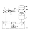
図5は従来の手動入力装置の基本構成を示す説明図である。
【0005】
従来の手動入力装置は、手動操作されるノブ80と、このノブ80の回転方向および回転量に応じて所定の操作感触を与えるモータ10と、このノブ80の回転量を検出する検出手段と、この検出手段による検出結果に応じてモータ10を制御する制御手段とを備えている。
【0006】
検出手段は、モータ10の出力軸11に固定される大プーリ200と、小プーリ201と、大プーリ200と小プーリ201とに巻き掛けられるベルト202と、エンコーダ30とによって構成されている。
【0007】
エンコーダ30は、円周に沿って図示しない複数のスリットが設けられ、小プーリ201と一体的に回転するコード板31と、このコード板31を挟んで対向する発光部35および受光部36とを備えている。受光部36はノブ80の回転方向および回転量に相当する検出信号をモータ10の制御手段である制御装置100に出力する。
【0008】
この制御装置100は、受光部36からの検出信号が入力される入力部101と、予め検出信号に対応するモータ10の制御信号をテーブルの形で記憶している記憶部103と、検出信号に応じて記憶部103に記憶されている制御信号を読み出す演算部102と、演算部102で読み出された制御信号をモータ10に出力する出力部104とを備えている。
【0009】
このように構成された従来の手動入力装置では、ノブ80を回転させると、大プーリ200および小プーリ201を介してコード板31が回転する。そして、受光部36は、スリットを通過した発光部35からの光を受けて、検出信号を制御装置100の入力部101に出力する。演算部102では、この検出信号に応じて記憶部103から制御信号が読み出される。この制御信号は、出力部104からモータ10に出力される。これにより、モータ10はノブ80の回転量や回転方向に応じて、その出力軸11を介してノブ80に回転力を伝える。
【0010】
このように回転力を与えられるノブ80では、例えば、ラジオの音量が調節される際に、操作者が音量の上がる方向にノブ80を回転させると、その回転方向に対抗する方向の回転力がモータ10によってノブ80に与えられ、これにより、操作者に抵抗感が与えられる。逆に、操作者が音量の下がる方向にノブ80を回転させると、その回転方向と同方向の回転力がモータ10によってノブ80に与えられ、これにより、操作者に加速感が与えられる。
【0011】
【発明が解決しようとする課題】
ところで、従来の手動入力装置では、小型化・軽量化を図る際、大プーリ200と小プーリ201が並列していることから、これら大プーリ200および小プーリ201を小さくすることが考えられる。しかし、小プーリ201を小さくし過ぎると、ベルト202との接触面積が小さくなり、大プーリ200からの回転の伝達効率が低下する。したがって、小プーリ201を小さくするには限界がある。また、ノブ80の回転をある程度の分解能を高めて検出する場合、その分解能は、小プーリ201の径寸法と大プーリ200の径寸法との比率で決定されるので、小プーリ201を小さくできないことに伴って、大プーリ200も大きくなりがちである。
【0012】
また、ノブ80を摘みやすくするためにある程度大きなものにすると、そのノブ80に直結されるモータ10は、そのノブ80の大きさに見合ったトルクを出力できなければならない。このため、モータ10も大きくなりやすい。
【0013】
これらのことから、従来の手動入力装置では小型化・軽量化が困難であり、したがって、自動車内などの限られたスペースに設けるには、好適なものではなかった。
【0014】
本発明は、上述の不備を考慮してなされたもので、その目的は、小型化・軽量化が可能な手動入力装置を提供することにある。
【0015】
【課題を解決するための手段】
上述の目的を達成するために、本発明の手動入力装置は、手動操作され、その手動操作による回転方向および回転量に応じた信号を送出させる操作部材と、この操作部材に、前記手動操作による回転方向および回転量に応じて所定の操作感触を与えるモータとを備えるとともに、サンギア、複数のプラネットギア、リングギア、キャリアおよびキャリア軸を有する遊星歯車機構と、この遊星歯車機構の前記リングギアを固定する固定部材と、前記モータの出力軸の回転を検出する検出手段と、この検出手段による検出結果に応じて前記モータの回転を制御する制御手段とを備え、前記モータの出力軸を前記サンギアに一体的に設け、前記操作部材を前記遊星歯車機構の前記キャリア軸に一体的に設け、前記複数のプラネットギアは、前記サンギアが挿通される挿通穴を有し前記キャリアと結合する規制部材と前記キャリアとの間に配置されることにより、自身の軸方向への移動を規制された構成にしてある。
【0016】
このように構成した手動入力装置では、操作部材を例えば時計回りに回転させると、この操作部材と一体のキャリア軸、すなわちキャリアが時計回りに回転する。このとき、リングギアが固定部材によって常に固定されているので、各プラネットギアは、反時計回りに自転しながらサンギアを中心に時計回りに公転する。そして、サンギアにプラネットギアの回転が伝達され、サンギアは時計回りに回転する。
【0017】
このとき、サンギアの回転は、サンギアとリングギアとの歯数比に応じて、操作部材の回転に対して増速されたものとなる。これにより、操作部材の回転量の分解能が高められる。検出手段では、このように回転するサンギアの回転、すなわちサンギアが固定されるモータの出力軸の回転が検出される。
【0018】
そして、制御手段は、検出手段による検出結果に応じてモータに回転力を出力させる。モータから出力された回転力、例えば反時計回りの回転力は、サンギアからプラネットギアに伝達される。このとき、リングギアが固定部材によって常に固定されているので、各プラネットギアには、時計回りに自転しながらサンギアを中心に反時計回りに公転する方向の回転力が与えられる。これに伴って、キャリア、すなわちキャリア軸には、反時計回りの回転力が与えられる。
【0019】
このキャリア軸の回転力は、サンギアとリングギアの歯数比に応じて、サンギアの回転力、すなわちこのサンギアと一体的に回転するモータの出力軸の回転力に対して増大されたものである。操作部材には、この増大された反時計回りの回転力が与えられる。これにより、操作者は操作部材を時計回りに回転させたときに操作感触として抵抗感を得ることができる。なお、このとき、モータを時計回りに回転させれば、操作部材には回転方向と同方向に回転力が与えられ、操作者は操作感触として加速感を得ることができる。
【0020】
この本発明では、上述のようにして操作者に所定の操作感触を与えることができ、したがって従来と同様の優れた操作性を有するものである。これに加えて、モータ、遊星歯車機構、検出手段および操作部材とを同軸上に配置できるので、手動入力装置全体をコンパクトにまとめることができる。したがって、小型化・軽量化が可能である。
【0021】
また、本発明では、操作部材の回転を検出するときに、遊星歯車機構によって操作部材の回転量の分解能を高めることができる。また、操作部材に回転力を与えるときに、遊星歯車機構によってモータから出力されたトルクを増大して操作部材に回転力を与えることができる。すなわち、遊星歯車機構を利用することによって、モータから出力されるトルクを増大させることと、操作部材の回転量の分解能を高めることとを、コンパクトな構造で行うことができる。したがって、この点においても小型化・軽量化が可能である。
【0022】
また、上述の手動入力装置の構成において、前記規制部材と前記キャリアは、前記軸方向への相対的な移動を規制し合った状態で、スナップ結合された構成としてもよい。
【0025】
【発明の実施の形態】
本発明の手動入力装置の一実施形態を図に基づいて説明する。
【0026】
図1は本実施形態の基本構成を示す説明図、図2は本実施形態の要部を示す横断面図、図3は図2のII−II断面図、図4は図2に示す要部の分解斜視図である。
【0027】
本実施形態は、前述した従来技術と同様に、例えば自動車に搭載されるエアコン、ラジオ、テレビ、オーディオなどの電気機器をそれぞれ異なる操作手段によって操作しようとすると、自動車の運転に支障をきたすことがあるので、運転の妨げにならないように、例えばエアコンの温度調節、ラジオのチューナの調節、テレビ、ラジオおよびオーディオの音量や音質の調節などを1つの手動入力装置で行うことを可能にした手動入力装置である。
【0028】
本実施形態は、図1に示すように、手動操作され、その手動操作による回転方向および回転量に応じた信号を送出させる操作部材、例えばノブ80と、このノブ80に、手動操作による回転方向および回転量に応じて所定の操作感触を与えるモータ10とを備えている。また、サンギア32、プラネットギア52、リングギア62、キャリア50およびキャリア軸51を有する遊星歯車機構と、モータ10の出力軸11の回転を検出する検出手段、すなわちエンコーダ30と、このエンコーダ30による検出結果に応じてモータ10の回転を制御する制御手段、すなわち制御装置100とを備えている。また、遊星歯車機構のサンギア32は、モータ10の出力軸11に一体的に設けてあり、ノブ80は遊星歯車機構のキャリア軸51に一体的に設けてある。
【0029】
制御装置100は、前述した従来技術に備えられているものと同様のものである。この制御装置100について、重複するが再度説明する。
【0030】
この制御装置100は、受光部36から出力された検出信号が入力される入力部101と、予め検出信号に対応する制御信号をテーブルの形で記憶している記憶部103と、検出信号に応じて記憶部103に記憶されている制御信号を読み出だす演算部102と、演算部102で読み出された制御信号をモータ10に出力する出力部104とを備えている。
【0031】
エンコーダ30は、図2,4に示すように、コード板31と、発光部35、受光部36および上述の制御装置100に接続されるコネクタ37と、これら発光部35、受光部36およびコネクタ37が設けられる基板34とから構成してある。コード板31には、円周に沿って複数のスリット33を設けてある。受光部36は、発光部35の光がスリット33を通過した光を受けて、ノブ80の回転方向および回転量に相当する検出信号を出力する。
【0032】
遊星歯車機構は、図2〜4に示すように、上述のサンギア32、プラネットギア52、リングギア62、キャリア50およびキャリア軸51とを備えている。サンギア32とリングギア62の歯数比は、例えば1:5に設定してある。
【0033】
サンギア32は、上述のコード板31と同軸上で一体に設けてある。プラネットギア52は規制部材40とキャリア50との間に3つ配置してある。キャリア50には、各プラネットギア52を回転可能に支持する3つのプラネットギア軸53と、キャリア軸51と、規制部材40と結合させるための結合部54とを設けてある。規制部材40は、円盤状の部材に、サンギア32を挿通する挿通穴41と、各プラネットギア軸53を支える支持穴43と、キャリア50の各結合部54に対応する結合部42とを備え、キャリア50と結合した状態でプラネットギア52の軸方向の移動を規制するものである。
【0034】
規制部材40の結合部42には、係合穴45を設けてあり、この結合部42の下部には嵌合穴44を設けてある。そして、キャリア50の係合部54には、係合穴45に係合する爪55と、嵌合穴44と嵌合する嵌合突部56とを設けてある。すなわち、規制部材40とキャリア50とは、軸方向の相対的な移動を規制し合った状態で、スナップ結合されるようにしてある。
【0035】
リングギア62は、同図2〜4に示すように、このリングギア62を常に固定する固定部材、すなわち円筒状のリングギアケース60内に設けてある。すなわち、リングギア62はこのリングギアケース60の内周面に一体に設けてある。このリングギアケース60内には、上述の規制部材40、プラネットギア52およびキャリア50が収納される。また、このリングギアケース60には、キャリア軸51を挿通するキャリア軸挿通部61を設けてある。
【0036】
本体ケース70は、同図2〜4に示すように、円筒状の部材の外周部に図示しないねじを挿通するねじ挿通部72と、上述のキャリア軸挿通部61とともにキャリア軸51を挿通するキャリア軸挿通部71と、上述の基板34を収納する基板収納部73とを備えている。また、本体ケース70の開口を形成する周縁部の各ねじ挿通部72付近には、突起部74を設けてある。
【0037】
ノブ80は、本体ケース70のキャリア軸挿通部72に挿通された上述のキャリア軸51に一体的に設けてある。
【0038】
モータ10は、同図2〜4に示すように、出力軸11を上述のサンギア32に固定された状態で、ブラケット20を介して本体ケース70に固定してある。ブラケット20には、本体ケース70の各ねじ挿通部72に対応する締結部22を設けてあり、この締結部22にはねじ挿通穴23と、上述の各突起部74が挿入される小穴24を設けてある。また、このブラケット20には、上述の基板34を取付ける取付部25,26を設けてある。
【0039】
また、本実施形態は、同図2〜4に示すように、ノブ80をその軸方向に移動可能に支持するガイド手段と、ノブ80を軸方向に付勢する付勢手段と、ノブ80の付勢手段に抗する移動に応じて所定のスイッチ、すなわちプッシュスイッチ90を作動させるスイッチ操作部94とを備えている。
【0040】
プッシュスイッチ90は、同図2,4に示すように、上述の基板34のノブ80側に設けてある。
【0041】
ガイド手段は、図3,4に示すように、リングギアケース60の外周面の4箇所に軸方向に沿って設けれるスライド凸部92と、本体ケース70の内周面の各スライド凸部92に対応する位置に設けられるスライド凹部93とによって構成した。
【0042】
付勢手段は、図2,4に示すように、キャリア50とサンギア32間に配置され、キャリア50を介してノブ80を付勢する復帰ばね91から成っている。
【0043】
スイッチ操作部94は、リングギアケース60の外周面に設けられ、この外周面から突出した板状部分から成っている。
【0044】
また、図2に示すように、キャリア軸51をリングギアケース60のキャリア軸挿通部61に挿通し、さらにケース本体70のキャリア軸挿通部71にキャリア軸51とキャリア軸挿通部61とを挿通した状態で、キャリア軸51の溝96にリングピン95を取付けてあり、これにより、キャリア軸51の軸方向の移動を規制させてある。
【0045】
このように構成した本実施形態では、図2において、ノブ80を例えば時計回りに回転させると、すなわちA方向に回転させると、このノブ80と一体的に回転するキャリア軸51、すなわちキャリア50が時計回りに回転する。このとき、リングギア62がリングギアケース60に常に固定されいるので、各プラネットギア52は、反時計回りに自転しながらサンギア32を中心に時計回りに公転する。そして、サンギア32にプラネットギア52の回転が伝達され、サンギア32は時計回りに回転する。なお、ノブ80が反時計回り、すなわちB方向に回転したのであれば、サンギア32は反時計回りで回転する。
【0046】
このとき、サンギア32の回転は、サンギア32とリングギア62との歯数比に応じて、キャリア軸51、すなわちキャリア軸51と一体的に回転するノブ80の回転に対して増速されたものとなる。これにより、ノブ80の回転量の分解能が高められる。エンコーダ30では、スリット33を通過した発光部35からの光を受光部36が受け、サンギア32と一体のコード板31の回転に基づいてモータ10の出力軸11の回転が検出される。なお、本実施形態では、サンギア32とリングギア62との歯数比を1:5に設定してあるので、ノブ80の回転量の分解能は5倍に高められる。
【0047】
そして、受光部36からは、上述のようにして検出した回転方向および回転量に相当する検出信号が出力され、この検出信号が制御装置100の入力部101に入力される。演算部102では、検出信号に応じた制御信号が記憶部103から読み出される。この制御信号は出力部104からモータ10に出力され、これにより、モータ10の出力軸11から回転力が出力される。
【0048】
このモータ10の出力軸11から出力された例えば反時計回りの回転力は、サンギア32からプラネットギア52に伝達される。このとき、リングギア62がリングギアケース60に常に固定されているので、各プラネットギア52には、時計回りに自転しながらサンギア32を中心に反時計回りに公転する方向に回転力が与えられる。これに伴って、キャリア50、すなわちキャリア軸51には、反時計回りの回転力が与えられる。
【0049】
このキャリア軸51の回転力は、サンギア32とリングギア62との歯数比に応じて、サンギア32の回転力、すなわちサンギア32と一体的に回転するモータ10の出力軸11の回転力に対して増大されたものとなる。ノブ80には、このように増大された反時計回りの回転力が与えられる。なお、モータ10の出力軸11の回転力が時計回りであれば、ノブ80には時計回りの回転力が与えられる。
【0050】
このように回転力を与えられるノブ80では、例えば、ラジオの音量が調節される際に、操作者が音量の上がるA方向にノブ80を回転させると、ノブ80にはA方向に対抗する方向の回転力がモータ10によって与えられ、これにより、操作者に抵抗感を与えることができる。逆に、音量の下がるB方向にノブ80が回転されると、ノブ80にはB方向と同方向の回転力がモータ10によって与えられ、これにより、操作者に加速感を与えることができる。したがって、操作者は、ノブの80の回転方向および回転量に応じた操作感触を得ることができる。
【0051】
また、本実施形態では、キャリア50がサンギア32とキャリア50間に配置された復帰ばね91のばね力によって、キャリア50が常にノブ80側に付勢されている。このキャリア50は、キャリア50とキャリア軸51の境目部分をリングギアケース60に押し付けられ、これに伴って、リングギアケース60は本体ケース70のノブ80側の内壁面に押し付けられている。これにより、ノブ80は、常にC方向に付勢されている。
【0052】
そして、ノブ80がD方向に押圧されると、キャリア50が復帰ばね91に抗して移動する。このとき、キャリア軸51に取付けたリングピン95が、リングギアケース60のキャリア軸挿入部61の端部を押圧し、これにより、リングギアケース60は、スライド凸部92およびスライド凹部93にガイドされながら、キャリア50と一体的に移動する。このようにリングギアケース60が移動すると、リングギアケース60と一体のスイッチ操作部94が移動し、これにより、プッシュスイッチ90がスイッチ操作部94に押圧され、スイッチが作動する。
【0053】
ノブ80が押圧から開放されると、キャリア50は復帰ばね91に押されて、リングギアケース60とともにもとの位置に戻る。このとき、プッシュスイッチ90からスイッチ操作部94が離れ、スイッチが作動しなくなる。
【0054】
このように本実施形態では、ノブ80の回転方向および回転量に応じて、ノブ80に同方向、または反対方向のモータ10から回転力が伝えられるので、操作者に抵抗感や加速感などの所定の操作感触を与えることができ、自動車などの運転中のように目が離せない場合に、ノブ80でどのような操作を行っているかを目視せずに把握できる。したがって、優れた操作性を得ることができる。
【0055】
また、本実施形態では、モータ10、遊星歯車機構、エンコーダ30およびノブ80とを同軸上に配置できるので、手動入力装置全体をコンパクトにまとめることができる。これにより、小型化・軽量化が可能である。特に小型化が可能なことから、自動車内などの限られたスペースに設けるのに好適である。
【0056】
また、ノブ80の回転がモータ10の出力軸11に伝達されるときに、遊星歯車機構によってノブ80の回転量の分解能を高めることができる。また、ノブ80を駆動させるときに、遊星歯車機構によってモータ10から出力されたトルクを増大してノブ80に回転力を与える。すなわち、遊星歯車機構を利用することによって、モータ10から出力されるトルクを増大させることと、ノブ80の回転量の分解能を高めることとを、コンパクトな構造で行うことができる。したがって、この点においても、小型化・軽量化が可能である。
【0057】
なお、モータ10の回転力を遊星歯車機構を介して増大してノブ80に伝えられることに伴って、そのモータ10の回転力を前述の従来技術の1/2以下にできたことを発明者は確認している。したがって、前述の従来技術よりも小型のモータを設けることができる。
【0058】
このような小型化・軽量化に伴って、本実施形態では、前述の従来技術と比較して体積は1/2以下に、重量は1/4以下にすることができたことを発明者は確認している。したがって、自動車内などの限られたスペースに設けるのに好適である。
【0059】
また、本実施形態では、ノブ80の押圧によってプッシュスイッチ90を作動させるようにしたので、ノブ80を押しボタンスイッチとして利用でき、これにより、1つの手動入力装置によって扱える機器数を増やすことができる。
【0060】
なお、本実施形態では、操作部材をノブ80としたが、本発明はこれに限るものではなく、レバーなどでもよい。
【0061】
【発明の効果】
以上、本発明では、操作者に所定の操作感触を与えることによって優れた操作性が得られるとともに、モータ、遊星歯車機構、検出手段および操作部材とを同軸上に配置できるので、本実施形態全体をコンパクトにまとめることができる。したがって、小型化・軽量化が可能である。特に小型化が可能なことから、限られたスペースに設けるのに好適である。
【0062】
また、操作部材の回転を検出するときに、遊星歯車機構によって操作部材の回転量の分解能を高めることができる。また、操作部材を駆動させるときに、遊星歯車機構によってモータから出力されたトルクを増大して操作部材に回転力を与えることができる。すなわち、遊星歯車機構を利用することによって、モータから出力されるトルクを増大させることと、操作部材の回転量の分解能を高めることとを、コンパクトな構造で実現でき、したがって、この点においても小型化・軽量化が可能である。
【図面の簡単な説明】
【図1】本発明の手動入力装置の一実施形態の基本構成を示す説明図である。
【図2】本実施形態の要部を示す横断面図である。
【図3】図2のII−II断面図である。
【図4】図2に示す要部の分解斜視図である。
【図5】従来の手動入力装置の基本構成を示す説明図である。
【符号の説明】
10 モータ
11 出力軸
30 エンコーダ(検出手段)
32 サンギア
50 キャリア
51 キャリア軸
52 プラネットギア
60 リングギアケース(固定部材)
62 リングギア
80 ノブ(操作部材)
90 プッシュスイッチ(スイッチ)
91 復帰ばね(付勢手段)
92 スライド凸部(ガイド手段)
93 スライド凹部(ガイド手段)
94 スイッチ操作部
100 制御装置(制御手段)[0001]
BACKGROUND OF THE INVENTION
The present invention is used, for example, for operation of an electric device mounted on an automobile, and gives an operation feeling to an operator who operates the operation member according to the rotation amount and rotation direction of the operation member manually operated such as a knob. It relates to a manual input device.
[0002]
[Prior art]
Conventionally, for example, automobiles are equipped with electric devices such as an air conditioner, a radio, a television, and an audio. If these electric devices are operated by different operation means, the driving of the automobile may be hindered. Therefore, for example, the temperature of an air conditioner, the adjustment of a radio tuner, the adjustment of the volume and sound quality of a television, radio and audio can be adjusted with one manual input device so as not to hinder driving. In this type of manual input device, a predetermined operation feeling is given to an operation member to be manually operated, for example, a knob gripped by an operator according to the rotation amount or rotation direction of the knob, thereby improving the operability of the knob. There is something that is.
[0003]
A conventional manual input device will be described below with reference to the drawings.
[0004]
FIG. 5 is an explanatory diagram showing a basic configuration of a conventional manual input device.
[0005]
A conventional manual input device includes a
[0006]
The detection means includes a
[0007]
The
[0008]
The
[0009]
In the conventional manual input device configured as described above, when the
[0010]
In the
[0011]
[Problems to be solved by the invention]
By the way, in the conventional manual input device, when the size and weight are reduced, the
[0012]
Further, if the
[0013]
For these reasons, it is difficult to reduce the size and weight of the conventional manual input device. Therefore, it is not suitable for providing in a limited space such as in an automobile.
[0014]
The present invention has been made in view of the above-mentioned deficiencies, and an object thereof is to provide a manual input device that can be reduced in size and weight.
[0015]
[Means for Solving the Problems]
In order to achieve the above-mentioned object, a manual input device of the present invention is manually operated, and an operation member that sends a signal according to the rotation direction and the rotation amount by the manual operation, and the operation member by the manual operation. A planetary gear mechanism having a sun gear, a plurality of planet gears, a ring gear, a carrier and a carrier shaft, and a ring gear of the planetary gear mechanism. A fixing member for fixing, a detecting means for detecting the rotation of the output shaft of the motor, and a control means for controlling the rotation of the motor according to a detection result by the detecting means, wherein the output shaft of the motor is connected to the sun gear. integrally provided, provided the operating member integrally on the carrier shaft of the planetary gear mechanism, the plurality of planet gears, said Sun By A is disposed between the carrier and the regulating member that binds to said carrier has an insertion hole to be inserted, are a configuration that is restricted from moving in the own axial direction.
[0016]
In the manual input device configured as described above, when the operation member is rotated, for example, clockwise, the carrier shaft integrated with the operation member, that is, the carrier rotates clockwise. At this time, since the ring gear is always fixed by the fixing member, the planet gears revolve clockwise around the sun gear while rotating counterclockwise. Then, the rotation of the planet gear is transmitted to the sun gear, and the sun gear rotates clockwise.
[0017]
At this time, the rotation of the sun gear is increased with respect to the rotation of the operation member in accordance with the gear ratio between the sun gear and the ring gear. Thereby, the resolution of the rotation amount of the operation member is increased. The detecting means detects the rotation of the sun gear rotating in this way, that is, the rotation of the output shaft of the motor to which the sun gear is fixed.
[0018]
And a control means makes a motor output rotational force according to the detection result by a detection means. The rotational force output from the motor, for example, the counterclockwise rotational force is transmitted from the sun gear to the planet gear. At this time, since the ring gear is always fixed by the fixing member, each planet gear is rotated in the clockwise direction while being rotated in the counterclockwise direction around the sun gear. Accordingly, a counterclockwise rotational force is applied to the carrier, that is, the carrier shaft.
[0019]
The rotational force of the carrier shaft is increased with respect to the rotational force of the sun gear, that is, the rotational force of the output shaft of the motor that rotates integrally with the sun gear, in accordance with the gear ratio of the sun gear and the ring gear. . This increased counterclockwise rotational force is applied to the operating member. Thereby, the operator can obtain a resistance feeling as an operation feeling when the operation member is rotated clockwise. At this time, if the motor is rotated clockwise, a rotational force is applied to the operation member in the same direction as the rotation direction, and the operator can obtain an acceleration feeling as an operation feeling.
[0020]
In the present invention, it is possible to give a predetermined operational feeling to the operator as described above, and therefore, it has excellent operability similar to the conventional one. In addition, since the motor, the planetary gear mechanism, the detection means, and the operation member can be arranged on the same axis, the entire manual input device can be made compact. Therefore, size reduction and weight reduction are possible.
[0021]
In the present invention, when detecting the rotation of the operation member, the planetary gear mechanism can increase the resolution of the rotation amount of the operation member. Further, when a rotational force is applied to the operation member, the torque output from the motor by the planetary gear mechanism can be increased to apply the rotational force to the operation member. That is, by using the planetary gear mechanism, it is possible to increase the torque output from the motor and increase the resolution of the rotation amount of the operation member with a compact structure. Therefore, also in this respect, it is possible to reduce the size and weight.
[0022]
In the configuration of the manual input device described above, the restriction member and the carrier may be snap-coupled in a state where relative movement in the axial direction is restricted .
[0025]
DETAILED DESCRIPTION OF THE INVENTION
An embodiment of a manual input device of the present invention will be described with reference to the drawings.
[0026]
1 is an explanatory diagram showing the basic configuration of the present embodiment, FIG. 2 is a cross-sectional view showing the main part of the present embodiment, FIG. 3 is a cross-sectional view taken along II-II in FIG. 2, and FIG. FIG.
[0027]
In the present embodiment, similarly to the above-described prior art, for example, if an electric device such as an air conditioner, a radio, a television, and an audio mounted on a car is operated by different operating means, the driving of the car may be hindered. Therefore, in order not to interfere with driving, for example, manual input that enables air conditioner temperature adjustment, radio tuner adjustment, television, radio and audio volume and sound quality adjustment, etc., to be performed with one manual input device. Device.
[0028]
In the present embodiment, as shown in FIG. 1, an operation member that is manually operated and sends a signal corresponding to the rotation direction and the rotation amount by the manual operation, for example, the
[0029]
The
[0030]
The
[0031]
As shown in FIGS. 2 and 4, the
[0032]
The planetary gear mechanism includes the
[0033]
The
[0034]
An engaging
[0035]
As shown in FIGS. 2 to 4, the
[0036]
As shown in FIGS. 2 to 4, the
[0037]
The
[0038]
2 to 4, the
[0039]
2 to 4, the present embodiment includes a guide means for supporting the
[0040]
As shown in FIGS. 2 and 4, the
[0041]
As shown in FIGS. 3 and 4, the guide means includes slide
[0042]
2 and 4, the biasing means includes a
[0043]
The
[0044]
2, the
[0045]
In the present embodiment configured as described above, in FIG. 2, when the
[0046]
At this time, the rotation of the
[0047]
Then, the
[0048]
For example, the counterclockwise rotational force output from the output shaft 11 of the
[0049]
The rotational force of the
[0050]
In the
[0051]
In the present embodiment, the
[0052]
When the
[0053]
When the
[0054]
As described above, in this embodiment, the rotational force is transmitted from the
[0055]
In the present embodiment, since the
[0056]
Further, when the rotation of the
[0057]
The inventor has been able to reduce the rotational force of the
[0058]
With such a reduction in size and weight, the present inventors have found that the volume can be reduced to ½ or less and the weight to ¼ or less compared to the above-described conventional technology. I have confirmed. Therefore, it is suitable for providing in a limited space such as in an automobile.
[0059]
In this embodiment, since the
[0060]
In the present embodiment, the operation member is the
[0061]
【The invention's effect】
As described above, according to the present invention, excellent operability can be obtained by giving a predetermined operational feeling to the operator, and the motor, the planetary gear mechanism, the detection means, and the operation member can be coaxially arranged. Can be summarized in a compact. Therefore, size reduction and weight reduction are possible. In particular, since it can be reduced in size, it is suitable for providing in a limited space.
[0062]
Further, when detecting the rotation of the operation member, the resolution of the rotation amount of the operation member can be increased by the planetary gear mechanism. Further, when the operating member is driven, the torque output from the motor by the planetary gear mechanism can be increased to apply a rotational force to the operating member. That is, by using the planetary gear mechanism, it is possible to increase the torque output from the motor and increase the resolution of the rotation amount of the operation member with a compact structure. Can be made lighter and lighter.
[Brief description of the drawings]
FIG. 1 is an explanatory diagram showing a basic configuration of an embodiment of a manual input device of the present invention.
FIG. 2 is a cross-sectional view showing a main part of the present embodiment.
3 is a cross-sectional view taken along the line II-II in FIG.
4 is an exploded perspective view of the main part shown in FIG. 2. FIG.
FIG. 5 is an explanatory diagram showing a basic configuration of a conventional manual input device.
[Explanation of symbols]
10 Motor 11
32
62
90 Push switch
91 Return spring (biasing means)
92 Slide convex part (guide means)
93 Slide recess (guide means)
94
Claims (2)
この操作部材に、前記手動操作による回転方向および回転量に応じて所定の操作感触を与えるモータとを備えるとともに、
サンギア、複数のプラネットギア、リングギア、キャリアおよびキャリア軸を有する遊星歯車機構と、
この遊星歯車機構の前記リングギアを固定する固定部材と、
前記モータの出力軸の回転を検出する検出手段と、
この検出手段による検出結果に応じて前記モータの回転を制御する制御手段とを備え、
前記モータの出力軸を前記サンギアに一体的に設け、
前記操作部材を前記遊星歯車機構の前記キャリア軸に一体的に設け、
前記複数のプラネットギアは、前記サンギアが挿通される挿通穴を有し前記キャリアと結合する規制部材と前記キャリアとの間に配置されることにより、自身の軸方向への移動を規制されたことを特徴とする手動入力装置。An operation member that is manually operated and sends a signal corresponding to the rotation direction and rotation amount by the manual operation;
The operation member is provided with a motor that gives a predetermined operation feeling according to the rotation direction and the rotation amount by the manual operation,
A planetary gear mechanism having a sun gear, a plurality of planet gears, a ring gear, a carrier and a carrier shaft;
A fixing member for fixing the ring gear of the planetary gear mechanism;
Detecting means for detecting rotation of the output shaft of the motor;
Control means for controlling the rotation of the motor according to the detection result by the detection means,
An output shaft of the motor is provided integrally with the sun gear,
The operation member is integrally provided on the carrier shaft of the planetary gear mechanism,
The plurality of planet gears are restricted between movement in the axial direction of the planet gears by being disposed between the carrier and a regulating member having an insertion hole through which the sun gear is inserted and coupled to the carrier. A manual input device characterized by.
Priority Applications (4)
| Application Number | Priority Date | Filing Date | Title |
|---|---|---|---|
| JP2001239504A JP3920599B2 (en) | 2001-08-07 | 2001-08-07 | Manual input device |
| EP02016914A EP1283534B1 (en) | 2001-08-07 | 2002-07-31 | Manual imput device capable of imparting manipulation feeling |
| DE60200502T DE60200502T2 (en) | 2001-08-07 | 2002-07-31 | Manual input device with force feedback function |
| US10/210,332 US6710565B2 (en) | 2001-08-07 | 2002-08-01 | Manual inputting device capable of imparting manipulation feeling |
Applications Claiming Priority (1)
| Application Number | Priority Date | Filing Date | Title |
|---|---|---|---|
| JP2001239504A JP3920599B2 (en) | 2001-08-07 | 2001-08-07 | Manual input device |
Publications (3)
| Publication Number | Publication Date |
|---|---|
| JP2003050639A JP2003050639A (en) | 2003-02-21 |
| JP2003050639A5 JP2003050639A5 (en) | 2005-04-07 |
| JP3920599B2 true JP3920599B2 (en) | 2007-05-30 |
Family
ID=19070241
Family Applications (1)
| Application Number | Title | Priority Date | Filing Date |
|---|---|---|---|
| JP2001239504A Expired - Fee Related JP3920599B2 (en) | 2001-08-07 | 2001-08-07 | Manual input device |
Country Status (1)
| Country | Link |
|---|---|
| JP (1) | JP3920599B2 (en) |
Families Citing this family (17)
| Publication number | Priority date | Publication date | Assignee | Title |
|---|---|---|---|---|
| US7124648B2 (en) | 2003-05-19 | 2006-10-24 | Alps Electric Co., Ltd. | Force feedback input device |
| JP2004342018A (en) | 2003-05-19 | 2004-12-02 | Alps Electric Co Ltd | Kinesthesia application type input device |
| JP2005018564A (en) * | 2003-06-27 | 2005-01-20 | Alps Electric Co Ltd | Inner force sense imparting type input device |
| JP4180455B2 (en) | 2003-07-24 | 2008-11-12 | アルプス電気株式会社 | Haptic input device |
| JP2005332157A (en) | 2004-05-19 | 2005-12-02 | Alps Electric Co Ltd | Haptic force application type input device |
| EP2279916B1 (en) * | 2008-05-26 | 2014-01-15 | Daesung Electric Co., Ltd | Steering wheel haptic switching unit and steering wheel haptic switching system having the same |
| EP2518592B1 (en) | 2011-04-25 | 2017-07-26 | Daesung Electric Co., Ltd | Haptic steering wheel switch apparatus |
| EP2518591B1 (en) | 2011-04-25 | 2018-05-30 | LS Automotive Technologies Co., Ltd. | Haptic steering wheel switch apparatus and haptic steering wheel switch system including the same |
| WO2016208455A1 (en) | 2015-06-22 | 2016-12-29 | アルプス電気株式会社 | Input device and method for controlling input device |
| JP6605702B2 (en) | 2016-02-18 | 2019-11-13 | アルプスアルパイン株式会社 | Operating device |
| JP6545893B2 (en) | 2016-02-26 | 2019-07-17 | アルプスアルパイン株式会社 | Operating device |
| CN108603272B (en) | 2016-03-07 | 2021-09-14 | 阿尔卑斯阿尔派株式会社 | Fe-based alloy composition, soft magnetic material, magnetic component, electrical/electronic related component, and device |
| JP6662692B2 (en) * | 2016-04-13 | 2020-03-11 | 株式会社東海理化電機製作所 | Shift device |
| EP3477418B1 (en) | 2016-06-27 | 2021-06-16 | Alps Alpine Co., Ltd. | Operation device and method for controlling same |
| JP6767217B2 (en) | 2016-09-16 | 2020-10-14 | アルプスアルパイン株式会社 | Input device |
| EP3514657A4 (en) | 2016-09-16 | 2020-06-17 | Alps Alpine Co., Ltd. | Operation feel imparting type input device |
| EP3561634A4 (en) | 2016-12-21 | 2020-07-29 | Alps Alpine Co., Ltd. | Operation device |
-
2001
- 2001-08-07 JP JP2001239504A patent/JP3920599B2/en not_active Expired - Fee Related
Also Published As
| Publication number | Publication date |
|---|---|
| JP2003050639A (en) | 2003-02-21 |
Similar Documents
| Publication | Publication Date | Title |
|---|---|---|
| JP3920599B2 (en) | Manual input device | |
| US6710565B2 (en) | Manual inputting device capable of imparting manipulation feeling | |
| JP4217567B2 (en) | Pedal reaction force device | |
| JP5973481B2 (en) | Operating wheel and handle system with tactile feedback | |
| US20060060019A1 (en) | Vehicular automatic transmission and automatic selector thereof | |
| JP2017114169A (en) | Shift device | |
| JPH11505193A (en) | Gear train for vehicle mirror adjustment | |
| US7298986B2 (en) | Image forming apparatus having a movable operation panel | |
| US7499023B2 (en) | Haptic feedback input device | |
| US6378388B1 (en) | Control panel with double rotary control for a motor vehicle | |
| JP2003050639A5 (en) | ||
| JPH09323559A (en) | Operation device of automatic transmission | |
| US20210364082A1 (en) | Shift device | |
| JP2003252074A (en) | By-wire type vehicle shift lever device | |
| JP5240076B2 (en) | Operating device | |
| EP0943907A1 (en) | Accelerator position sensor | |
| JP2003185013A (en) | Gear shift control device for vehicle | |
| JP5254345B2 (en) | Vehicle range switching device | |
| JP4034536B2 (en) | Manual input device | |
| JPH039576Y2 (en) | ||
| JP3660172B2 (en) | Automotive electronic devices | |
| JPH03282054A (en) | Operation device for automatic transmission for vehicle | |
| JP4992429B2 (en) | Position detection device | |
| JP2001223481A (en) | Lid opening/closing control device | |
| JPH02275173A (en) | Shift lever device for automatic transmission |
Legal Events
| Date | Code | Title | Description |
|---|---|---|---|
| A521 | Written amendment |
Free format text: JAPANESE INTERMEDIATE CODE: A523 Effective date: 20040513 |
|
| A621 | Written request for application examination |
Free format text: JAPANESE INTERMEDIATE CODE: A621 Effective date: 20040513 |
|
| A977 | Report on retrieval |
Free format text: JAPANESE INTERMEDIATE CODE: A971007 Effective date: 20060613 |
|
| A131 | Notification of reasons for refusal |
Free format text: JAPANESE INTERMEDIATE CODE: A131 Effective date: 20060620 |
|
| A521 | Written amendment |
Free format text: JAPANESE INTERMEDIATE CODE: A523 Effective date: 20060807 |
|
| A02 | Decision of refusal |
Free format text: JAPANESE INTERMEDIATE CODE: A02 Effective date: 20061031 |
|
| A521 | Written amendment |
Free format text: JAPANESE INTERMEDIATE CODE: A523 Effective date: 20061221 |
|
| A911 | Transfer to examiner for re-examination before appeal (zenchi) |
Free format text: JAPANESE INTERMEDIATE CODE: A911 Effective date: 20070109 |
|
| TRDD | Decision of grant or rejection written | ||
| A01 | Written decision to grant a patent or to grant a registration (utility model) |
Free format text: JAPANESE INTERMEDIATE CODE: A01 Effective date: 20070206 |
|
| A61 | First payment of annual fees (during grant procedure) |
Free format text: JAPANESE INTERMEDIATE CODE: A61 Effective date: 20070215 |
|
| R150 | Certificate of patent or registration of utility model |
Free format text: JAPANESE INTERMEDIATE CODE: R150 Ref document number: 3920599 Country of ref document: JP Free format text: JAPANESE INTERMEDIATE CODE: R150 |
|
| FPAY | Renewal fee payment (event date is renewal date of database) |
Free format text: PAYMENT UNTIL: 20100223 Year of fee payment: 3 |
|
| FPAY | Renewal fee payment (event date is renewal date of database) |
Free format text: PAYMENT UNTIL: 20110223 Year of fee payment: 4 |
|
| FPAY | Renewal fee payment (event date is renewal date of database) |
Free format text: PAYMENT UNTIL: 20120223 Year of fee payment: 5 |
|
| FPAY | Renewal fee payment (event date is renewal date of database) |
Free format text: PAYMENT UNTIL: 20120223 Year of fee payment: 5 |
|
| FPAY | Renewal fee payment (event date is renewal date of database) |
Free format text: PAYMENT UNTIL: 20130223 Year of fee payment: 6 |
|
| FPAY | Renewal fee payment (event date is renewal date of database) |
Free format text: PAYMENT UNTIL: 20140223 Year of fee payment: 7 |
|
| S533 | Written request for registration of change of name |
Free format text: JAPANESE INTERMEDIATE CODE: R313533 |
|
| R350 | Written notification of registration of transfer |
Free format text: JAPANESE INTERMEDIATE CODE: R350 |
|
| LAPS | Cancellation because of no payment of annual fees |