JP3920436B2 - Switching apparatus, traffic management device and switching method in ATM network - Google Patents
Switching apparatus, traffic management device and switching method in ATM network Download PDFInfo
- Publication number
- JP3920436B2 JP3920436B2 JP00033898A JP33898A JP3920436B2 JP 3920436 B2 JP3920436 B2 JP 3920436B2 JP 00033898 A JP00033898 A JP 00033898A JP 33898 A JP33898 A JP 33898A JP 3920436 B2 JP3920436 B2 JP 3920436B2
- Authority
- JP
- Japan
- Prior art keywords
- cells
- traffic management
- atm
- internet protocol
- cell
- Prior art date
- Legal status (The legal status is an assumption and is not a legal conclusion. Google has not performed a legal analysis and makes no representation as to the accuracy of the status listed.)
- Expired - Fee Related
Links
Images


Classifications
-
- H—ELECTRICITY
- H04—ELECTRIC COMMUNICATION TECHNIQUE
- H04L—TRANSMISSION OF DIGITAL INFORMATION, e.g. TELEGRAPHIC COMMUNICATION
- H04L49/00—Packet switching elements
- H04L49/25—Routing or path finding in a switch fabric
- H04L49/256—Routing or path finding in ATM switching fabrics
- H04L49/257—Cut-through or wormhole routing
-
- H—ELECTRICITY
- H04—ELECTRIC COMMUNICATION TECHNIQUE
- H04L—TRANSMISSION OF DIGITAL INFORMATION, e.g. TELEGRAPHIC COMMUNICATION
- H04L49/00—Packet switching elements
- H04L49/20—Support for services
-
- H—ELECTRICITY
- H04—ELECTRIC COMMUNICATION TECHNIQUE
- H04L—TRANSMISSION OF DIGITAL INFORMATION, e.g. TELEGRAPHIC COMMUNICATION
- H04L49/00—Packet switching elements
- H04L49/25—Routing or path finding in a switch fabric
- H04L49/251—Cut-through or wormhole routing
-
- H—ELECTRICITY
- H04—ELECTRIC COMMUNICATION TECHNIQUE
- H04L—TRANSMISSION OF DIGITAL INFORMATION, e.g. TELEGRAPHIC COMMUNICATION
- H04L49/00—Packet switching elements
- H04L49/30—Peripheral units, e.g. input or output ports
-
- H—ELECTRICITY
- H04—ELECTRIC COMMUNICATION TECHNIQUE
- H04L—TRANSMISSION OF DIGITAL INFORMATION, e.g. TELEGRAPHIC COMMUNICATION
- H04L49/00—Packet switching elements
- H04L49/30—Peripheral units, e.g. input or output ports
- H04L49/3081—ATM peripheral units, e.g. policing, insertion or extraction
-
- H—ELECTRICITY
- H04—ELECTRIC COMMUNICATION TECHNIQUE
- H04L—TRANSMISSION OF DIGITAL INFORMATION, e.g. TELEGRAPHIC COMMUNICATION
- H04L49/00—Packet switching elements
- H04L49/60—Software-defined switches
- H04L49/602—Multilayer or multiprotocol switching, e.g. IP switching
-
- H—ELECTRICITY
- H04—ELECTRIC COMMUNICATION TECHNIQUE
- H04L—TRANSMISSION OF DIGITAL INFORMATION, e.g. TELEGRAPHIC COMMUNICATION
- H04L49/00—Packet switching elements
- H04L49/60—Software-defined switches
- H04L49/606—Hybrid ATM switches, e.g. ATM&STM, ATM&Frame Relay or ATM&IP
-
- H—ELECTRICITY
- H04—ELECTRIC COMMUNICATION TECHNIQUE
- H04Q—SELECTING
- H04Q11/00—Selecting arrangements for multiplex systems
- H04Q11/04—Selecting arrangements for multiplex systems for time-division multiplexing
- H04Q11/0428—Integrated services digital network, i.e. systems for transmission of different types of digitised signals, e.g. speech, data, telecentral, television signals
- H04Q11/0478—Provisions for broadband connections
-
- H—ELECTRICITY
- H04—ELECTRIC COMMUNICATION TECHNIQUE
- H04L—TRANSMISSION OF DIGITAL INFORMATION, e.g. TELEGRAPHIC COMMUNICATION
- H04L12/00—Data switching networks
- H04L12/54—Store-and-forward switching systems
- H04L12/56—Packet switching systems
- H04L12/5601—Transfer mode dependent, e.g. ATM
- H04L2012/5614—User Network Interface
- H04L2012/5616—Terminal equipment, e.g. codecs, synch.
-
- H—ELECTRICITY
- H04—ELECTRIC COMMUNICATION TECHNIQUE
- H04L—TRANSMISSION OF DIGITAL INFORMATION, e.g. TELEGRAPHIC COMMUNICATION
- H04L12/00—Data switching networks
- H04L12/54—Store-and-forward switching systems
- H04L12/56—Packet switching systems
- H04L12/5601—Transfer mode dependent, e.g. ATM
- H04L2012/5638—Services, e.g. multimedia, GOS, QOS
- H04L2012/5646—Cell characteristics, e.g. loss, delay, jitter, sequence integrity
- H04L2012/5652—Cell construction, e.g. including header, packetisation, depacketisation, assembly, reassembly
- H04L2012/5653—Cell construction, e.g. including header, packetisation, depacketisation, assembly, reassembly using the ATM adaptation layer [AAL]
- H04L2012/5658—Cell construction, e.g. including header, packetisation, depacketisation, assembly, reassembly using the ATM adaptation layer [AAL] using the AAL5
-
- H—ELECTRICITY
- H04—ELECTRIC COMMUNICATION TECHNIQUE
- H04L—TRANSMISSION OF DIGITAL INFORMATION, e.g. TELEGRAPHIC COMMUNICATION
- H04L12/00—Data switching networks
- H04L12/54—Store-and-forward switching systems
- H04L12/56—Packet switching systems
- H04L12/5601—Transfer mode dependent, e.g. ATM
- H04L2012/5638—Services, e.g. multimedia, GOS, QOS
- H04L2012/5665—Interaction of ATM with other protocols
- H04L2012/5667—IP over ATM
-
- H—ELECTRICITY
- H04—ELECTRIC COMMUNICATION TECHNIQUE
- H04L—TRANSMISSION OF DIGITAL INFORMATION, e.g. TELEGRAPHIC COMMUNICATION
- H04L49/00—Packet switching elements
- H04L49/25—Routing or path finding in a switch fabric
- H04L49/253—Routing or path finding in a switch fabric using establishment or release of connections between ports
-
- H—ELECTRICITY
- H04—ELECTRIC COMMUNICATION TECHNIQUE
- H04L—TRANSMISSION OF DIGITAL INFORMATION, e.g. TELEGRAPHIC COMMUNICATION
- H04L49/00—Packet switching elements
- H04L49/30—Peripheral units, e.g. input or output ports
- H04L49/3009—Header conversion, routing tables or routing tags
Description
【0001】
【発明の属する技術分野】
本発明は、非同期転送モード(ATM)交換装置内でのセグメント化−および−再組立て(SAR:segmentation−and−reassembly)デバイスに対するインターフェイシングに関する。
【0002】
【従来の技術】
添付図面の図1は、ATM通信ネットワーク内で使用するための従来の交換装置の各部分を示す。図1の装置は、複数N−1の物理レイヤデバイス21 ,22 …2N-1 および対応する複数N−1のトラフィック管理デバイス41 ,42 …4N-1 を含んでなる。各々のトラフィック管理デバイス4i は、双方向データ送達経路6i によってその対応する物理レイヤデバイス2i に接続されている。
【0003】
図1の装置はまた、例えばN×Nのクロス−コネクト交換ユニットであるスイッチ体8をも含んでいる。実際にスイッチ体8は、N個の入力ポートとN個の出力ポートを有する。各々のトラフィック管理デバイス4i は、双方向データ送達経路10i によって、1つの入力ポートおよび1つの出力ポートからなる1つのポート対に接続される。したがって、簡略化のために、図1にはポート対のみが示されている。
【0004】
図1の装置はまた、双方向データ送達経路10N によりスイッチ体8のポート対Nに接続されているセグメント化−および−再組立て(SAR)デバイス12も含んでいる。このSARデバイス12はというと、付随するメモリ14に接続されている。最後に、装置1は、トラフィック管理デバイス41 〜4N-1 の各々とメモリが14とに接続されたホストプロセッサ(またはスイッチ制御装置)16を含む。
【0005】
図1の装置の使用において、物理レイヤデバイス21 〜2N-1 は、装置1に対し、物理レイヤ伝送ラインに接続されている複数の双方向ポート(ユーザーネットワークインタフェースまたはUNIポート)を提供する。これらの物理レイヤ伝送ラインは、例えば、同期デジタルハイアラーキ(SDH)または同期光通信網(SONET)伝送ライン(ITU−T規格G.709)、プレシオクロナスデジタルハイアラーキ(PDH)伝送ライン(ITU−T G.703規格)、またはファイバ分布データインタフェース(FDDI)伝送ライン(ATMフォーラムにより規定された4b/5b規格)であってよい。ATMネットワーク内では、これらの伝送ラインは、関係する伝送ラインを提供するのに用いられる特定の物理媒体に応じたフォーマットをもつビットストリーム形式でATMセルを伝送する。データ受信方向(セルが交換装置内に受入れられる方向)において、物理レイヤデバイス21 〜2N-1 は、装置のUNIポートで受信されたビットストリームを、それぞれのデータ送達経路61 〜6N-1 を介してトラフィック管理デバイス41 〜4N-1 に送達されるATMセルのストリームへと変換する。
【0006】
トラフィック管理デバイス41 〜4N-1 は、スイッチ体8へのATMセルの送信を制御する。スイッチ体8は、その入力ポートのうちの選択されたものから、その出力ポートのうちの選択されたものへのデータ輸送を可能にするのに各々役立つ最高N本の同時データ転送経路を提供することができる。トラフィック管理デバイスは、ATMセルを同期的にイクスチェンジ(交換)するためにこれらのデータ転送経路を使用する。イクスチェンジプロセスの全体的な制御は、通常、トラフィックフロー条件を監視し、装置の中を通る異なるセルフローの間での交換資源の公平な割当てを提供する目的で、連続するタイムスロット内のデータ転送経路を選択するホストプロセッサ16によって実行される。
【0007】
トラフィック管理デバイス4は、スイッチ体により提供されるデータ転送経路の1つを通してATMセルを受信した後、そのセルをデータ送達経路6を介してその対応する物理レイヤデバイスに転送する。各物理レイヤデバイス2は、それが受信したATMセルのストリームを、当該物理レイヤデバイスのUNIポートに接続されたATM伝送ライン上の伝送に適したビットストリームへと変換する。
【0008】
図1の装置が使用されるATMネットワークでは、伝送されるATMセルトラフィックの全てとはいわないまでも大部分が、音声信号、ビデオ信号、ファイル等のいずれを表すにせよ、ユーザデータである。しかしながら、ネットワークにより伝送されるトラフィックの中には、不可避的に、シグナリングメッセージといったような制御情報を含んでいるものもある。このようなシグナリングメッセージは、例えば呼出を設定するために必要とされる。さらに、いわゆる「ホスト間通信メッセージ」を用いて、ATMネットワーク(図1に示されているホストプロセッサ16を含む)の異なるノードにおいてホストプロセッサが互いにやりとりすることが必要とされることもある。
【0009】
シグナリングメッセージおよびホスト間通信メッセージは、普通のデータトラフィックと全く同じようにATMセルの形でATMネットワーク内を転送される。ただし、このようなメッセージを構成するセルは、通常各セルのヘッダ内に含まれている仮想パス識別子(VPI)および仮想チャネル識別子(VCI)情報によって、データを表すセルとは、ある意味で区別される。シグナリングメッセージおよびホスト間通信メッセージは一般に、単一のATMセルのペイロード内に収まるには長過ぎる。したがって、このような各メッセージの発信元において、該メッセージは複数のATMセルに変換され、これらのセルは次にネットワーク内に連続的に送り込まれる。このプロセスは、セグメント化と呼ばれる。メッセージの着信先にて、そして場合によっては当該メッセージに対しアクセスすることが望まれるATMネットワークの任意の中間ノードにて、そのメッセージを構成するATMセルは、再組立てと呼ばれるプロセスの中で組合わされてもとのメッセージを再生する。図1に示されている交換装置においては、これらのセグメント化および再組立てプロセスは、従来スイッチ体8の独自の専用ポート対(図1内のポートN)を備えるセグメント化および再組立て(SAR:segmentation−and−reassembly)デバイス12によって実施される。したがって、それがシグナリングメッセージまたはホスト間通信メッセージに属することをそのVPI/VCIフィールドにて表示しているATMセルが、トラフィック管理デバイス4の1つ(「ソース」トラフィック管理デバイス)によって受信されたという情報をホストコンピュータ16が受けたときに、ホストプロセッサ16は、ソーストラフィック管理デバイスが接続されているスイッチ体8の入力ポート(例えば、トラフィック管理デバイス41 の場合の入力ポート1)から、スイッチ体8の出力ポートNまでデータ転送経路を形成させ、かくして当該セルはソーストラフィック管理デバイスからSARデバイス12まで送信され得るようになる。このときSARデバイス12は、メモリ14を用いて、このセルを、同じメッセージに属するその他のセルと組合わせ、ひとたびそのメッセージについての再組立てプロセスが完了すると、ホストプロセッサ16によりメッセージを読み取ることが可能となる。
【0010】
ホストプロセッサ16がシグナリングメッセージまたはホスト間通信メッセージの発信元である場合、これはそのメッセージをメモリ14に送信し、SARデバイス12は次にメッセージをセグメント化して、複数のATMセルを生成する。これらのセルは次に、メッセージの着信先に到達するようセルがそれを通ってルーティングされなくてはならない伝送ラインに、その対応する物理レイヤデバイスが接続されているトラフィック管理デバイスであるようなトラフィック管理デバイスのうちの1つ(「デスティネーション」トラフィック管理デバイス)に連続的に転送される。ホストプロセッサ16の制御のもとで、スイッチ体8の入力ポートNからデスティネーション(宛先)トラフィック管理デバイスが接続されているスイッチ体の出力ポートまで、メッセージの連続する各セルについて、1つのデータ転送経路が提供される。このデスティネーショントラフィック管理デバイス4に到達した後、セルは次にデータ送達経路6を介して対応する物理レイヤデバイス2まで渡され、メッセージの着信先へさらに伝送するためUNIポートの1つを通して、要求された伝送ラインへと出力される。
【0011】
【発明が解決しようとする課題】
図1の装置において、SARデバイス12には、スイッチ体上で独自の専用ポート対(ポートN)が具備されており、したがってシグナリングメッセージおよびホスト間通信メッセージは全てスイッチ体8を通過する。このようなメッセージに関与するATMセルの数は、スイッチ体を通るATMセルの合計数に比べて比較的少ないものの、シグナリングおよびホスト間通信メッセージを構成するATMセルをスイッチ体の中に通す必要性は、不可避的にスイッチ体内の輻輳を招き、ユーザーデータを表すATMセルを交換する機会の数を少なくする。その上、スイッチ体のポート対の1つがSARデバイス12専用でなくてはならないことから、トラフィック管理デバイスとの接続に利用できるポート対の数は1つ減る。このことは究極的に、全体として交換装置のUNIポートの数を制限する。
【0012】
したがって本発明は、上記問題を解決することのできる、ATMネットワークにおける、交換装置、トラフィック管理デバイスおよび交換方法を提供することを目的とするものである。
【0013】
【課題を解決するための手段】
本発明の第1の形態によると、ATMネットワーク内で使用するための交換装置において、ATMセルを交換するためのスイッチ体;ATMセルからのパケットを再組立てするための再組立て手段、および、交換装置に送信されたATMセルを受信するように接続され、また第1のデータ送達経路手段により前記スイッチ体へそして第1のデータ送達経路手段とは分離した第2のデータ送達経路手段によって、前記再組立て手段へ接続されており、さらに、再組立て手段による再組立てを必要とする1または複数の予め定められたパケットタイプに属する受信ATMセルをそれぞれの再組立てセルとして識別するように作動可能であると共に、このような識別された再組立てセル以外の受信セルを、また前記スイッチ体による交換のため前記第1のデータ送達経路手段を介してスイッチ体に対し送信するように作動可能であり、そして前記再組立てセルを、再組立て手段によりパケットに再組立てするため前記第2のデータ送達経路手段を介して前記再組立て手段に送信するように作動可能であるトラフィック管理手段;を含んでなる交換装置が提供されている。
【0014】
本発明の第2の形態によると、ATM交換装置に送信されたATMセルを交換するためのスイッチ体を有し、またATM交換装置に送信されたATMセルからパケットを再組立てするための再組立て手段をも有する該ATM交換装置内で使用するためのトラフィック管理デバイスにおいて、ATMセルを受信するためのセル受信手段;前記セル受信手段に接続され、ATM交換装置の前記再組立て手段による再組立てを必要とする1または複数の予め定められたパケットタイプに属するような受信セルをそれぞれの再組立てセルとして識別するように作動するセル識別手段;およびデバイスが使用中であるときに前記スイッチ体に接続するように適合されている第1のポート手段をもち、またデバイスが使用中であるときに前記再組立て手段に接続するよう適合されている、前記第1のポート手段とは分離した第2のポート手段を有し、識別された再組立てセル以外の受信セルを前記第1のポート手段に送信し、前記再組立てセルを前記第2のポート手段に送信するように作動可能である、セル出力手段、を含んでなるトラフィック管理デバイスが提供されている。
【0015】
本発明の第3の形態によると、ATMセルを交換するためのスイッチ体、ATMセルからパケットを再組立てするための再組立て手段およびATMネットワーク交換装置に送信されたATMセルを受信するためのトラフィック管理手段を含む該ATMネットワーク交換装置内で使用するための交換方法において、再組立て手段による再組立てを必要とする1または複数の予め定められたパケットタイプに属するような受信ATMセルが、それぞれの再組立てセルとしてトラフィック管理手段によって識別され;そしてかかる識別された再組立てセル以外の受信セルがトラフィック管理手段によって第1のデータ送達経路手段を介してスイッチ体に送信され、スイッチ体により交換され、識別された再組立てセルは、第1のデータ送達経路手段とは分離した第2のデータ送達経路手段を介して、トラフィック管理手段から再組立て手段まで送信され、再組立て手段によりパケットに再組立てされる、交換方法が提供されている。
【0016】
本発明の第1から第3の形態においては、再組立てを必要とするセルは、スイッチ体の中を通ることなく再組立て手段に直接送ることができる。したがって、スイッチ体のスイッチポートは全て、非再組立てセルを交換するために、トラフィック管理手段による使用が可能である。したがって、スイッチスループットは増大し交換装置内での回線争奪の問題も軽減される。
【0017】
再組立てを必要とするパケットは、例えば、シグナリングメッセージ(特にAAL5メッセージ)またはホスト間通信メッセージ(特にATMユーザ・ネットワークインタフェース(UNI)管理エンティティの間の中間ローカル管理インタフェース(ILMI)通信)であってよい。
再組立てを必要とするパケットにはまた、インターネットプロトコルパケットが含まれる。この場合、装置に好ましくはさらに、交換装置を通るパケットフローを検出すべく、このような再組立てされたインターネットプロトコルパケットを検査するため前記再組立て手段と接続されたインターネットプロトコルスイッチ制御装置手段も含んでいる。このとき、トラフィック管理手段は、インターネットプロトコルスイッチ制御装置手段により必要とされるセルを、スイッチ体の中に通すことなく直接この手段に送ることができる。
好ましくは、トラフィック管理手段は、そのデフォルトルーティングモードで、予め定められたデフォルト入力仮想チャネルを介してATMネットワークの上流ノードからのインターネットプロトコルパケットを受信し、前記予め定められたデフォルト入力仮想チャネルに属する受信ATMセルをこのような再組立てセルとして識別し、前記インターネットプロトコルスイッチ制御装置手段が、再組立てされたパケットの検査によりパケットフローを検出できるようにすべく前記再組立て手段に対し前記第2のデータ送達経路手段を介してこれらのセルを送信するように作動可能である。
【0018】
トラフィック管理手段はまたこのようなパケットフローが前記インターネットプロトコルスイッチ制御装置手段によって検出されたときに、前記予め定められたデフォルト入力仮想チャネルとは異なる新しい入力仮想チャネルを介してトラフィック管理手段により、検出後のパケットフローを構成する後続パケットのセルが受信され、かかる再組立てセルとしてこれらのセルが識別されず、前記第1のデータ送達経路手段を介してスイッチ体に対し直接送信される、カットスルー交換モードにて作動するように交換が可能である。
【0019】
このようにして、検出されたフローに属するセルは、フローのうちのセルが直接ハードウェア内にルーティングされるいわゆるカットスルー交換を実現すべく、インターネットプロトコルスイッチ制御装置手段により交換装置内で再組立てされることなく交換装置を通ってルーティングされ得る。例えば、前記インターネットプロトコルスイッチ制御装置手段がかかるパケットフローを検出したときは、トラフィック管理手段は、前記スイッチ体を介して検出されたパケットフローのセルを交換するための帯域幅を確保させられる。
【0020】
好ましくは、前記インターネットプロトコルスイッチ制御装置手段によってパケットフローに属するものとして検出されず再組立てされたパケットは、フローに属さないIPパケットの蓄積交換ルーティングを実行すべく、前記スイッチ体への送信のためトラフィック管理手段に戻すように転送される複数のセルに、セグメント化される。前記スイッチ体を通過した後、前記複数のうちのセルは次に、予め定められたデフォルト出力仮想チャネルを介してATMネットワークの下流ノードに出力され得る。一方、トラフィック管理手段が前記カットスルー交換モードで作動している間、検出されたパケットフローを構成する前記後続パケットのセルは、好ましくは、前記予め定められたデフォルト出力仮想チャネルとは異なる新しい出力仮想チャネルを介してトラフィック管理手段によって出力される。
【0021】
1つの実施例においては、前記トラフィック管理手段には、各受信ATMセルのヘッダの仮想パス識別子および/または仮想チャネル識別子フィールドを検査し、かかる検査の結果に基づいて当該セルがこのような再組立てセルとして識別されるべきか否かを決定すべく作動可能なセル識別手段が含まれている。こうして、再組立てセルを迅速かつ容易に識別することが可能となっている。
【0022】
好ましくは、装置にはさらに、セグメント化手段(セグメント化手段および再組立て手段は、同一のセグメント化および再組立てデバイスの一部をなす)が含まれ、このセグメント化手段はまた前記第2のデータ送達経路手段によって前記トラフィック管理手段に接続され、装置内でローカルに生成されたパケットを複数のATMセルへセグメント化し、前記第2のデータ送達経路手段を介してトラフィック管理手段へ前記複数のうちのセルを送信するように作動可能である。この構成において、セグメント化の結果として得られるセルはまた、スイッチ体を通過することなくトラフィック管理手段に送信され得る。
【0023】
この場合、第2のデータ送達経路手段にはそれぞれの単方向送信受信経路手段が含まれ、その受信経路手段はトラフィック管理手段から再組立て手段まで、識別された再組立てセルを送信するように機能し、その送信経路手段は、前記セグメント化手段からトラフィック管理手段まで前記複数のうちのセルを送信するように機能する。
【0024】
好ましい実施例では、前記トラフィック管理手段には、スイッチ体によって提供されたデータ転送経路を介してATMセルを交換するため前記第1のデータ送達経路手段により前記スイッチ体にそれぞれ接続されている複数の個別トラフィック管理デバイスが含まれており、前記第2のデータ送達経路手段には、再組立て手段に対し、そして具備されている場合には前記セグメント化手段に対して、個別トラフィック管理デバイスを共通に接続するバス手段(例えば、Universal−Test−and−Operations−PHY−Interface−for−ATM(UTOPIA)レベル2「ルックアライク(lookalike)」バス手段)が含まれている。この構成では、各トラフィック管理デバイスは、スイッチ体の1または複数の付随する入力ポートに対するセルの送信を制御し、各トラフィック管理デバイスは、バス手段を用いて再組立て手段に直接、任意の再組立てセルを送ることができる。
【0025】
異なるトラフィック管理デバイスがバス手段を共有できるようにするためには、前記再組立て手段が前記バス手段のマスターデバイスとして作動可能であり、各トラフィック管理デバイスがこのバス手段のスレーブデバイスとして作動可能であることが好ましい。この場合、例えば前記再組立て手段には、トラフィック管理デバイスのいずれかが受信したATMセルをそのような再組立てセルとして識別したか否かを決定すべく、該トラフィック管理デバイスをポーリングするためのポーリング手段および前記トラフィック管理デバイスのうちの1つがそのような再組立てセルを識別したことを前記ポーリング手段が決定した場合に、そのセルを有するトラフィック管理デバイスが前記バス手段を介して再組立て手段にそれを送信するようにさせるべく作動可能なデータ読取り手段、が含まれている。
【0026】
本発明の第4の形態によると、ATMネットワーク内で使用するための交換装置において:ATMセルを交換するためのスイッチ体;交換装置内でローカルに生成されたパケットを複数のATMセルにセグメント化するためのセグメント化手段;および第1のデータ送達経路手段により前記スイッチ体に接続され、またこの第1のデータ送達経路手段とは分離した第2のデータ送達経路手段によって、前記セグメント化手段に接続され、しかも、スイッチ体によって交換されたセルを前記第1のデータ送達経路手段を介してスイッチ体から受信しかつ前記複数のセルを前記第2のデータ送達経路手段を介してセグメント化手段から受信し、スイッチ体から受信した交換後のセルおよびセグメント化手段から受信した前記複数のセルを含むATMセルストリームを出力するように作動するトラフィック管理手段、を含んでなる交換装置が提供されている。
【0027】
本発明の第5の実施形態によると、ATM交換装置に送達されたATMセルを交換するためのスイッチ体を有し、またATM交換装置から出力されるべき複数のATMセルへと、装置によってローカルに生成されたパケットを、セグメント化するためのセグメント化手段も有するATM交換装置の中で使用するためのトラフィック管理デバイスにおいて、デバイスが使用中であるとき前記スイッチ体に接続するように適合された第1のポート手段をもち、またデバイスが使用中であるとき前記セグメント化手段に接続するように適合された、前記第1のポート手段とは分離した第2のポート手段をも有し、しかも、スイッチ体によって交換されたセルを前記第1のポート手段で受信し前記複数のセルを前記第2のポート手段で受信するように作動可能であるセル入力手段;およびスイッチ体から受信された交換後のセルを含み、また前記複数のセルをも含むATMセルストリームを出力するためのセル出力手段を含んでなるトラフィック管理デバイスが提供されている。
【0028】
本発明の第6の形態によると、ATMセルを交換するためのスイッチ体、ATM交換装置内でローカルに生成されたパケットを複数のATMセルにセグメント化するためのセグメント化手段および、交換されたセルを出力するためのトラフィック管理手段を含む該ATMネットワーク交換装置内で使用される交換方法において:
スイッチ体によって交換されたセルが、第1のデータ送達経路手段を介してスイッチ体からトラフィック管理手段によって受信され;セグメント化手段によって生成された複数のセルが、前記第1のデータ送達経路手段とは分離した第2のデータ送達経路手段を介してトラフィック管理手段によって受信され;スイッチ体から受信された交換後のセルおよびセグメント化手段から受信された前記複数のセルを含むATMセルストリームが、トラフィック管理手段によって出力される、交換方法が提供されている。
【0029】
本発明の第4〜第6の形態においては、本発明の第1〜第3の形態により達成された利点に対応する利点が、交換装置が再組立て手段をもたない場合でさえ得ることができる。セグメント化の結果として得られたセルは、スイッチ体を通過することなくトラフィック管理手段に対し直接転送され得、非セグメント化セルのためのスイッチ体のスイッチポートを解放し、輻輳を軽減する。
【0030】
本発明の第7の形態によると、ATMネットワーク内で使用するための交換装置において:ATMセルを交換するためのスイッチ体;交換装置を通るインターネットプロトコルフローを検出するためのインターネットプロトコルスイッチ制御装置手段;および該交換装置に送信されたATMセルを受信するために接続され、また第1のデータ送達経路手段により前記スイッチ体にまた第1のデータ送達経路手段とは分離した第2のデータ送達経路手段により前記インターネットプロトコルスイッチ制御装置手段に接続され、しかもそのデフォルトルーティングモードにおいて、予め定められたデフォルト入力仮想チャネルに属する受信ATMセルをデフォルトルーティングセルとして識別し、前記第2のデータ送達経路手段を介して前記インターネットプロトコルスイッチ制御装置手段にこれらのセルを送信して、前記インターネットプロトコルスイッチ制御装置手段が送信されたセルの検査からかかるフローを検出できるようにすべく作動可能であり、しかもこのようなフローが前記インターネットプロトコルスイッチ制御装置手段によって検出されたときに、前記予め定められたデフォルト入力仮想チャネルとは異なる新しい入力仮想チャネルを介してトラフィック管理手段により検出されたフローを構成する後続して受信されたセルが受信されかかるデフォルトルーティングセルとしてこれらのセルが識別されず前記第1のデータ送達経路手段を介してスイッチ体に直接送信されるようなカットスルー交換モードにて作動するように交換が可能であるトラフィック管理手段を含んでなる交換装置が提供される。
【0031】
本発明の第8の実施形態によると、装置に送信されたATMセルを交換するためのスイッチ体を有しまた交換装置を通るインターネットプロトコルフローを検出するためのインターネットプロトコルスイッチ制御装置手段をも有するATM交換装置内で使用するためのトラフィック管理デバイスにおいて:ATMセルを受信するためのセル受信手段;デバイスが使用中であるときに前記スイッチ体に接続するように適合されている第1のポート手段をもち、またデバイスが使用中であるときに前記インターネットプロトコルスイッチ制御装置手段に接続するよう適合されている、前記第1のポート手段とは分離した第2のポート手段を有するセル出力手段;および前記セル受信手段に接続され、そのデフォルトルーティングモードにおいて、予め定められたデフォルト入力仮想チャネルに属するような受信ATMセルをデフォルトルーティングセルとして識別しかつ前記インターネットプロトコルスイッチ制御装置への転送のため前記第2のポート手段にこれらのセルを送信して前記インターネットプロトコルスイッチ制御装置手段が送信されたセルの検査によりかかるフローを検出できるようにすべく作動可能であり、しかもこのようなフローが前記インターネットプロトコルスイッチ制御装置手段によって検出された時点で、前記予め定められたデフォルト入力仮想チャネルとは異なる新しい入力仮想チャネルを介してトラフィック管理デバイスにより検出されたフローを構成する後続して受信されたセルが受理されかかるデフォルトルーティングセルとしてこれらのセルが識別されずスイッチ体に対する直接的転送のため第1のポート手段に送信されるようなカットスルー交換モードにて作動するように、交換が可能であるセル識別手段を含んでなるトラフィック管理デバイスが提供される。
【0032】
本発明の第7および第8の形態においては、インターネットプロトコルスイッチ制御装置手段が、トラフィック管理手段から受信された識別後のデフォルトルーティングセルを再組立てするための再組立て手段をもつことは不要である。
ここで、例として、添付図面を参照する。
【0033】
【発明の実施の形態】
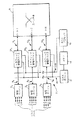
図2は、本発明を実施するATM交換装置の各部分を示す。図2では、図1を参照して前述した各部分に対応する部分が同じ参照番号で表されている。
図2の交換装置21では、各々のトラフィック管理デバイス241 〜24N は、図1において述べたトラフィック管理デバイス41 〜4N-1 に比べて修正されている。図1の装置と同様に、各々のトラフィック管理デバイス24i はデータ送達経路6i (i=1〜N)を用いてその対応する物理レイヤデバイス2i に接続される。各々のデータ送達経路6i は、最高622Mbps(クロック周波数≦50MHz )でのデータ転送のための16ビットのデータ経路を各方向に提供するUniversal Test and Operations PHYインタフェース(UTOPIA)レベル2である。したがって、各々の物理レイヤデバイス2および各々のトラフィック管理デバイス4は2つのポート(1つは送信、もう1つは受信用)をもち、両方のポート共、同じプロトコルおよびインタフェース定義を使用する。
【0034】
簡略化のため、図2では各々のトラフィック管理デバイス24i に接続された状態で1つの物理レイヤデバイス2i だけが示されているが、UTOPIAレベル2経路6i は実際には、ATMレイヤが155Mbpsで作動する場合にはn≦8,ATMレイヤが622Mbpsで作動する場合にはn≦4として、各トラフィック管理デバイスに対し最高n個の物理レイヤデバイスの接続を可能にする。UTOPIAレベル2のインタフェースは、5つのアドレッシングラインを含み、かくして最高8個の物理レイヤデバイス上で最高31のポートについての仮想空間を提供する。
【0035】
UTOPIAレベル2インタフェースのさらに完全な記述は、ATM Forumが刊行した「UTOPIA」,ATM−PHYインタフェース仕様書、レベル2、バージョン1.0″,1995年6月、に見出すことができる。
各トラフィック管理デバイス24i はまた、データ送達経路10i によって、入力ポートおよび出力ポートからなるスイッチ体8のポート対に接続される。データ送達経路10i は、並列または直列の適切なあらゆるタイプのものであってよいが、当該実施例においては、トラフィック管理デバイス24i において具備されたデータ送達経路10i に対するインタフェースは、UTOPIAレベル2「ルックアライク(lookalike)」(UL2LAL)インタフェースである。これは基本的に、ATM Forumにより公表された上述のUTOPIAレベル2標準インタフェースと同じ特性を有するが、UTOPIA標準インタフェースは物理レイヤデバイスに対しATMレイヤデバイス(例えばトラフィック管理デバイス)に接続するように意図されているのであって、トラフィック管理デバイスやスイッチ体といったような2つのATMレイヤデバイス間の接続を提供することを目的としていないため、標準インタフェースの「ルックアライク(類似した)」インタフェースであるものとして記述されている。
【0036】
また、データ送達経路10i が並列/直列コンバータを含み、かくして経路がトラフィック管理デバイス24i に接続された端部では並列となるようにそしてスイッチ体に接続された端部では直列となるようにすることも可能である。こうして、スイッチ体8上の接続ピンの数を、本出願人の同時係属英国特許出願第9617110.3号に記述されているように減少させることが可能となる。代替的または付加的に、ここでもまた、当該出願人の同時係属出願番号第9617110.3号に記述されているように、スイッチ体8上に必要とされる接続ピンの数を減少させる目的で、時分割多重化ベースで同じポート対に複数のトラフィック管理デバイスを接続することができる。この出願および当該出願人のもう1つの同時係属英国特許出願第9617100.4号の内容は、本明細書に参考として含まれている。
【0037】
各トラフィック管理デバイス24i はまた、ホストバス28を介してホストプロセッサ16に接続される。ホストバスは例えば、N個の異なるトラフィック管理デバイス241 〜24N を個々にアドレス(ポーリング)するのに充分な数のアドレスラインを備えた双方向32ビット幅のデータ経路である。
図2に示されている交換装置21は、まず第1に、以下SARバスと呼ぶもう1本のバス26が、“セグメント化および再組立て”(SAR)デバイス12へ各トラフィック管理デバイス241 〜24N を接続するために具備されているという事実によって、図1に示されている交換装置1とは異なっている。したがって、図1の交換装置の場合とは異なり、SARデバイス12は、スイッチ体8のポート対の1つに接続されていない。SARバス26は、好ましくは1/2幅(各方向に8ビットのデータ)のUL2LALインタフェースである。この場合、SARデバイス12は、SARバス26に対する制御を有するマスターデバイスであり、各々のトラフィック管理デバイス241 〜24N はスレーブデバイスである。あるいは、SARバス26は、トラフィック管理デバイス24およびSARデバイス12のピン数(pin count)を減少させるために、高速直列バスであってもよい。第2のバスは、低圧差信号(LVDS:Low Voltage Differential Signals)を転送するのに用いることができる。
【0038】
SARデバイス12は、例えば、出願人が製造しているMB86687Aタイプであってもよい。
ここで図2の装置の動作について記述する。ただし、装置の詳細な説明について記述する前に、図2の交換装置を使用することのできる広帯域デジタル統合サービス網(B−ISDN)について図3を参照しながら概略的に説明しておく。図2の交換装置がB−ISDN内での使用にだけ供されるものではなく、B−ISDNには本発明の実施例が実際に取り扱おうとしている種類の多数のシグナリングメッセージ(およびホスト間通信メッセージ)を発生させるコネクション型通信プロトコルを含むことから、説明を目的とした好例を提供するのにB−ISDNが役立つということも理解できるであろう。しかしながら、ATMネットワーク内で使用される全ての通信プロトコルには、コネクションレス型プロトコルさえも、そして不可避的にシグナリングメッセージの生成および処理も含み、本発明の実施例はこのようなネットワーク全てに有利に適用できる。
【0039】
図3に示されているB−ISDNネットワーク100は、異なる顧客宅内にそれぞれ対応する複数の顧客宅内(CP:Customer premises)ノード102をもつ。各CPノードにおいて、ユーザが供給する任意にフォーマットされた情報はATMセルストリームへと変換され、逆方向より、ネットワークから受信されたATMセルストリームは、必要とされるフォーマットのユーザ情報へと変換される。これらの変換は、ターミナルアダプタの機能を果たすCPノード内のATMアダプテーションレイヤ(AAL)によって実行される。低帯域ATMセルストリームを生成し受信するだけのCPノードは、通常、固定点伝送設備により、遠隔マルチプレクサノード(RMN)106に接続され、ここで個々の低帯域ATMセルストリームは、統計的に集線リンク108へ多重化またはここから分離される。いくつかのこのような集線リンク108はアクセスノード(AN)110に接続され、このアクセスノードには、リンク112により、より高い帯域のCPノード102を接続することもできる。アクセスノード110から出現する高度に多重化されたATMセルストリームは、ローカル交換ノード(LEN)114まで伝送され、このノード114にはその他のRMN106さらには超高帯域CPノード102もまた接続できる。図2の交換装置は、例えば、LEN114内で使用できる。LEN114は、LEN114よりも大きいATMスイッチであるタンデム交換ノード(TEN)116に接続される。ここでもまた、図2の交換装置をTEN116内で使用することができる。
【0040】
図3内に示されているB−ISDNネットワーク100は、コネクション型通信プロトコルを必要とするコネクション型ネットワークである。コネクション型プロトコルは、異なるCPノード間の情報フローが、ルーティング情報を含むヘッダフィールドを伴うATMセルの形をしていようとも、コールセットアップ手順を必要とする。コールセットアップ手順は、コネクションを伴う全てのATMセルによって使用されるべき経路またはルートを選択し、例えば図3中のリンク108といったネットワークの各物理リンクに現れる呼量は、そのリンクを共有するコネクションの数を制限することによって、制御される。経路は、輻輳を回避する目的で、全てのネットワークリンクおよびパケット交換ノード(例えばLEN114およびTEN116)の間での全負荷を公平に分散するように、選択される。
【0041】
新しいコネクションが許容される場合には、そのコネクションに対し「仮想コネクション」番号(すなわち特定の仮想パス識別子(VPI)および仮想チャネル識別子(VCI)値)が割当てられ、そしてその番号は、そのコネクションに属する全てのATMセルのVPI/VCIフィールド内に現れる。仮想コネクション番号は、呼設定のときに各パケットについての発呼元および着呼先の両方を暗示的に識別する。選択された経路に沿った各スイッチは、割当てられた仮想コネクション番号についての情報を、シグナリングメッセージを用いて受けると、その仮想コネクション番号を含むATMセルが到着する毎に、各スイッチには従うべきルーティング命令が与えられる。
【0042】
コネクション型通信プロトコルは、呼処理機能によって実行される。この機能は一般に、地域的に分布した各CPノードに備えられたプロセッサへの機能分散であるが、説明の都合上、呼処理機能は単一の中央プロセッサにより実行されるものと見なしてもよい。各CPノードは、中央のコールプロセッサとの通信のためそれに割当てられたパーマネント仮想チャネル番号を有し、中央のコールプロセッサは、通常のCPノードを通してトランスポートネットワークに接続される。したがってトランスポートネットワークには、そのコールプロセッサが、その他の何らかのユーザまたはアプリケーションであるかのように見える。特定のCPノード(「ソース」CPノード)でのユーザは、もう1つの所望のCPノード(「デスティネーション」CPノード)に対するコネクションを要求すべくそのCPノードからコールプロセッサまでのパーマネント仮想コネクションを使用することができる。要求されたコネクションは、全二重動作を可能にすべく、双方向であってよい。コールプロセッサは、デスティネーションCPノードに、該CPノードが要求されたコネクションを受入れたいか否かを照会するため、該コールプロセッサからデスティネーションCPノードまでのパーマネント仮想コネクションを用いる。受入れたい場合、コールプロセッサは、要求された新しい仮想コネクションがロードされた時点でなおも、その経路をすでに用いている他のコネクションの各々が現在享受しているサービスの質が保証最低レベル以上に維持され得るようにする、1本の経路を見い出そうと試みる。
【0043】
デスティネーションCPノードが、そのコネクションを受入れることを拒絶した場合または適当な経路を発見できない場合、コネクションは阻止され、ソースCPノードは、コールプロセッサからソースCPノードまでのパーマネント仮想コネクションを介して送られるシグナリングメッセージを用いてその事実についての情報を受ける。一方、コネクションを設定できる場合、選択された経路に沿った全ての交換ノードはプロセッサにより新しい仮想コネクション番号についての情報を受け、適当なルーティング命令を受ける。この目的のため、シグナリングメッセージは、パーマネント仮想コネクションを介してコールプロセッサから当該交換ノードまで送られる。これらのシグナリングメッセージは、例えば図2の交換装置内のホストプロセッサ16といった交換ノード内のホストプロセッサに送信される必要がある。図2の装置自体の中でシグナリングメッセージが取扱われる方法については、後でさらに詳細に考察する。
【0044】
ちなみに、パーマネント(予め構成された)仮想コネクションに加えて、交換された(ダイアルアップコネクティビティ)仮想コネクションもまた、シグナリングメッセージを伝送するのに使用できる。
呼がひとたび設定されたならば、ソースおよびデスティネーションCPノードは、割当てられた経路(もしくは2重化コネクションの場合には、複数の経路)を通して情報の交換を行う。割当てられた経路に沿って通過する各ATMセルは、そのヘッダ内に割当てられた仮想コネクション番号を含み、要求されたルーティングを決定するために交換ノードによりヘッダのみが(実時間で、好ましくは可能なかぎりVLSI回路を用いて)処理される。したがって、与えられた仮想コネクションを伴う全てのセルは、ネットワークを通して同じルートを進み、これらのセルが生成されたのと同じ順序で送信される。
【0045】
ソースまたはデスティネーションCPノードのいずれかが呼を終了することを望む場合、呼設定のときと同様のプロセスが呼の復旧を行うのに使用される。ここでもまた、ソースおよびデスティネーションCPノードとコールプロセッサおよびコールプロセッサと当該交換ノードとの間でシグナリングメッセージを送るのに、パーマネント仮想コネクションが用いられる。
【0046】
図3のネットワークでは、ユーザ情報がATMセルの形で伝送されるのと全く同様に、ソースおよびデスティネーションCPノードとの間およびコールプロセッサと交換ノードとの間のシグナリングメッセージは、ATMセルの形で伝送される。ユーザ情報およびシグナリングメッセージのATMセルへの変換は、ATMアダプテーションレイヤ(AAL)の機能である。
【0047】
図3に示されているCPノードの中の1つのCPノードの動作に関係するプロトコルを示す図4を参照すると、CPノードのためのATMアダプテーションレイヤは、複数のタイプのサービスを支援する必要があろう。ユーザサービスには、コネクション型、コネクションレス型そして場合によってはその他のタイプの可変ビットレート(VBR)サービス、および固定ビットレート(CBR)サービスが含まれる。VBRサービスは、さまざまな異なるピークデータ転送速度をもつ非持続型のトラフィック、例えばバーストデータトラフィック、イメージファイル、大形データベースファイル転送、パケットビデオおよびパケットボイスを支援する。一方、CBRサービスの方は、例えばデジタルビデオおよび64Kビット/秒のデジタルボイスといった、長時間にわたる一定のデータ転送速度をもつ持続型トラフィックを支援する。さらにもう1つのVBRサービスとして、制御信号(シグナリングメッセージ)が提供される。
【0048】
AALは、ユーザが生成した情報信号を受信するユーザインタフェースと、制御信号を受信する制御インタフェースとを有する。AALは、情報および制御信号をATMネットワーク内へ導入するに先立ってATMに適した標準フォーマットに変換し、また、ユーザおよび制御インタフェースへの出力に先立ちネットワークから到着したATMセルから情報信号および制御信号を再構成するためのものである。
【0049】
AALの方は、図4に示されているように2つのサブレイヤに分割される。コンバージェンスサブレイヤ(CS)は、ユーザ生成信号および制御信号のためのカプセル化/非カプセル化機能を果す。実際、図5に示されているとおり、例えばAAL3/4およびAAL5といったある種のタイプのAALにおいては、CSサブレイヤはさらに共通部コンバージョンサブレイヤ(CPCS:common part conversion sub−layer)とサービス特定コンバージェンスサブレイヤ(SSCS)に細分される。特定AALユーザサービスを支援するために、一定数のSSCSプロトコルがすでに定義づけられており、また現在開発中である。AAL5は一般に、シグナリングメッセージのために使用される。
【0050】
AAL5に関係する図6に示されているとおり、ソースCPノードにおいて、ATMネットワークを通して伝送され究極的にはデスティネーションCPノードに送信されるべきもとのユーザ生成情報信号または制御信号が、(備わっている場合にはSSCS内での処理の後で)CPCSサービスデータユニット(CPCS−SDU)の形でCPCSに送信される。CPCSにおいては、信号(CPCS−SDU)は、図7に示されているように、そのペイロードとしてCPS5プロトコルデータユニット(CPCS−PDU)内にカプセル化される。CPCS−PDUはまた、最高で長さ47オクテットでありうるパディングフィールドおよび図7にそのフォーマットがさらに詳しく示されている8オクテットのトレーラも有している。CPCS−ユーザ−ツー−ユーザ(CPS−UU)インジケーションフィールドが、CPCSユーザ−ツー−ユーザ情報をトランスペアレントに転送するために用いられる。現在、トレーラの64ビットのアラインメントを指示するのに共通部インジケータ(CPI)のみが使用され、0にセッされているが、将来的な機能としては、障害監視の目的等のための管理メッセージの識別およびオペレーションおよびメンテナンス(OAM)メッセージの識別が含まれる。長さフィールドは単にCPCS−PDUペイロードの長さを表示する。ペイロードの長さは、1〜65535オクテットの範囲内にあり、オクテット整列されていなければならない。情報の喪失または取得を検出するため、受信部はその長さフィールドを用いる。長さフィールドは、オクテットの数の2進コードである。CPCS−PDU内のビットエラーを検出するために巡回冗長検査(CRC)フィールドが使用される。CRCの対象範囲は、パディングフィールド、CPCS−UU,CPIおよび長さフィールドを含めたCPCS−PDU全体を網羅する。
【0051】
図6に示されているように、CPCS−PDUはヘッダを有していないものの、サービス特定コンバージェンスサブレイヤ(SSCS)によりヘッダがすでに付加されている可能性もあり、その場合には、そのヘッダはそれ相応にCPCS−SDUの一部をなすことになる。
このときCPCS−PDU全体は、可変長の単一フィールドとしてCPCS−PDUを処理するSARサブレイヤ(図4)に移される。図6に示されているとおり、このときSAR機能は、CPCS−PDUを、各々1つのSAR−PDUのペイロードを構成する48オクテットのセグメントに分割することである。最後のセグメントは、全48オクテットのペイロードを形成すべくパディングを必要とすることもあろう。SAR−PDUはさらに、図8に示されているとおり5バイトのヘッダを含む。
【0052】
AAL5 SAR機能においては、その主な焦点は効率性にあり、したがって、ユーザまたは制御情報を伝送するのに、ATMセルペイロード内で利用可能な48オクテットが全て用いられる。したがって、メッセージの始め、続きまたは終りを指示するのに、SAR−PDUペイロードのオクテットのいずれをも利用できない。その代わり、メッセージの始め、続きおよび終りを、SAR機能によって検出するのに、ATMセルヘッダのペイロードタイプ(PT)フィールドが用いられる。PTフィールド内で通常のPT情報がなおも伝送されるが、図8に示されているペイロードタイプのコーティングを生成するためにATM−レイヤ−ユーザ−ツ−ATM−レイヤ−ユーザ(AUU)パラメータで符号化される。
【0053】
こうして、AAL5レイヤによって実行されたセグメント化プロセスは完了する。再組立てプロセスは、基本的にセグメント化プロセスの逆であり、複数のSAR−SDUからメッセージ(CPCS−SDUまたは該当する場合にはSSCS−SDU)を再構成するのに役立つ。
図4内のATMレイヤは、53オクテットのATMセルを形成すべく、各SAR−PDUへまたはそこから5バイトのヘッダを付加または除去する働きをする。物理レイヤは、伝送リンク媒体へセルを乗せまたはこの伝送リンク媒体からセルを受信する働きをする。シグナリングメッセージがそれに特定的に向けられている場合を除いて、図3に示されたATMネットワークのノードすなわち遠隔マルチプレクサ、アクセス、ローカル交換機およびタンデム交換ノードは、ATMセルヘッダ上のみで動作する。ここに48バイトのセルペイロードは、ATMネットワークエンティティによって処理されず、また読取られることさえない。
【0054】
図4に示されているさまざまなレイヤに加えて、図3のB−ISDNネットワークのためのプロトコルレイヤモデルはまた、CPノード内の全てのユーザおよび制御レイヤの管理を担う管理プレーンを含む。管理プレーンは、例えばコールセットアップ手順に関与する。管理プレーンのレイヤ管理エンティティが、ユーザおよび制御レイヤの各々をインタフェースする働きをし、これらのレイヤが(ローカル管理の目的かまたは遠隔CPノードの管理プレーンへの伝送のため)これらのレイヤに命令を与える役目と(いくつかの遠隔CPノードの管理プレーン内で生成されたかまたはローカルに生成された)これらのレイヤからの応答を受け取る役目とを果す。
【0055】
ここで図2に戻ると、交換装置21は、図3に示されたATMネットワークの交換ノード、例えばそのローカル交換ノード(LENS)114またはタンデム交換ノード(TENs)116に具備される。装置21の4N個のUN1ポートは、その交換ノードをその他の交換ノードにリンクするまたはアクセスノード(AN)110の1つまたは顧客宅内(CP)ノード102の1つといったようなATMネットワークエンティティにリンクする、異なるそれぞれのATM伝送ラインに接続される。
物理レイヤデバイス21 〜2N は、UNIポートに接続されたATM伝送ラインから受信されたそれぞれのビットストリームを、ATMレイヤデバイスであるトラフィック管理デバイス241 〜24N への伝送のために適したATMセルストリームへと変換する。物理レイヤデバイス2により実行される機能としては、セル速度のデカップリング(decoupling)、ヘッダエラー制御(HEC)ヘッダ順序生成(sequence generation)/確認(verification);セルのデニリエーション(delineation);伝送フレームアダプテーション;伝送フレーム生成および再生;およびビットタイミング、が含まれる。伝送フレームアダプテーション、生成および再成機能が必要とされるのは、物理レイヤにおける情報か、例えばITU−T G.707,G.708、およびG.709同期デジタルハイアラーキ(SDH)フォーマット、STM−1フォーマット(155.52Mbit/秒)またはITU−T G.751プレシオクロナスデジタルハイアラーキ(PDH)E3フォーマット(34.368Mbit/秒)といった、任意の適当なフレームフォーマットで伝送されるからである。その他の適当なフォーマットとしては、ATM Forumにより規定されているようなファイバ分散データインタフェース(FDDI)4b/5bがある。
【0056】
物理レイヤデバイス21 〜2N によって生成されるそれぞれのATMセルストリームは、それぞれのデータ送達経路6i 〜6N を介して対応するトラフィック管理デバイス241 〜24N に転送される。
図9は、トラフィック管理デバイス24の1つの概略図である。トラフィック管理デバイスは、入力部32と出力部34を含む。入力部32は、セル受信回路322、セル識別(ID)回路324、およびセル出力回路326を含む。セル出力回路326は、入力部32をスイッチ体に付随する入力ポートにリンクするデータ送達経路10の伝送部分に接続された第1のポートP1および、入力部32をSARデバイス12にリンクするための、SARバス26に接続された第2のポートP2を有する。
【0057】
物理レイヤデバイス2から入力部32に到着したセルは、セル受信回路322によって受信される。
セル受信回路322の制御下で、トラフィック管理デバイスに到着したセルは通常、トラフィック管理デバイスの一部をなすかまたはさらに通常は図9に示されているように1本のバスでトラフィック管理デバイスに接続されたスタティックRAMといった別のメモリデバイスである受信メモリ36に、一時的にバッファされる。受信メモリ36は、例えば、N個の異なるトラフィック管理デバイスにそれぞれ対応する複数の受信待ち行列RQ1 〜RQN として形成することができる。以下でさらに詳しく説明するように、もう1つの受信待ち行列(receive queue)RQSAR もまた受信メモリ36内に設けられる。
【0058】
各受信待ち行列RQはまた、異なるトラフィックプライオリティレベルにそれぞれ対応する複数のサブ待ち行列SQ0 〜SQ3 に細分化することもできる。図9では、プライオリティレベル3(最下位レベル)は、利用可能ビットレート(ABR)および非特定ビットレート(VBR)トラフィックに対応し、プライオリティレベル2は、非実時間(non−real−time)可変ビットレート(NRT−VBR)ドラフィックに対応し、プライオリティレベル1は、実時間(RT)VBRトラフィックに対応し、プライオリティレベル0(最高位レベル)は固定ビットレート(CBR)トラフィックに対応する。
【0059】
セル識別回路324において、各受信セルのセルヘッダは、もう1つのATMネットワークエンティティのホストプロセッサから発信されたシグナリングメッセージまたはホスト間通信メッセージの一部をそのセルが形成しているか否かを決定するために検査される。このようなセルは、セルヘッダのVPI/VCIフィールドに基づいて、ユーザデータセルと区別できる。例えば、このようなシグナリングおよびホスト間通信メッセージの通信のために確保されたパーマネント仮想コネクションは全て5という特別なVCI値(ただし任意の適当なVPI値)を有することができる。こうして、シグナリングおよびホスト間通信メッセージに属するセルを、通常のデータメッセージを構成する他のセルと区別することができる。
【0060】
シグナリングメッセージの例としては、(前述した通りの)コールセットアップメッセージおよびポイントツーマルチポイント接続のセットアップメッセージが含まれる。ポイントツーマルチポイントのシグナリングメッセージはまた、個々のリンクが一度に1つずつ別々にセットアップされることから、5というVCI値を使用する。専用シグナリングメッセージの他の例としては、メタ(Meta)シグナリングメッセージ(VPI=任意、VCI=1)および一般同報通信(General Broadcast)シグナリング(VPI=任意、VCI=2)が含まれる。さらにホスト間通信メッセージは、メッセージを構成するセルに特別なVPI/VCIの組合せを割当てることによって識別されるユーザ定義メッセージを含むことができる。さらに、ホスト間通信メッセージにはまた、「ATMユーザ−ネットワークインタフェース仕様書」、第3.1版、第4節:中間ローカル管理インタフェース仕様の中でさらに詳しく記述されているように、隣接するATM UNI管理エンティティ(UMEs:UNI Management Entities)間の中間ローカル管理インタフェース(ILMI:Interium Local Management Interface)通信も含むことができる。このようなILMI通信メッセージに属するセルにはまた、単数または複数の特定のVPI/VCI値(例えばVCI=16,VCI=任意の適当な値)が割り振られることになる。
【0061】
受信セルがユーザ−データセルであることをセル識別回路324が決定すると、当該セルのためのデスティネーショントラフィック管理デバイスが、入力部によってアクセス可能なルーティングテーブルを用いて、識別される、そしてセルは、デスティネーショントラフィック管理デバイス(およびセルプライオリティレベル)に対応する受信待ち行列RQ(および備わっている場合にはサブ待ち行列SQ)の中に格納される。ホストプロセッサが交換装置内の輻輳を検出できるようにする目的で、ホストバス28を介してホストプロセッサ16により、異なる受信待ち行列の充てんレベルを定期的に読み取ることができる。
【0062】
トラフィック管理デバイスは、連続するタイムスロット内にて同期的に動作する。各タイムスロットにおいて、各トラフィック管理デバイスのセル出力回路326は、装置内のトラフィック管理デバイスのうちのもう1つのトラフィック管理デバイスに対して1つ(または場合によって複数の)ATMセルを転送でき、スイッチ体8は、入力ポートの1つと出力ポートの1つとの間にあるデータ転送経路を最高N個備える。セルは、セル出力回路326の第1のポートD1から出力される。伝送すべきセルをどの受信待ち行列から取り出すかの選択は、ホストプロセッサ16よりトラフィック管理デバイスに与えられたスケジューリング情報に基づいて、セル出力回路326によって行われる。スケジューリングを決定する上で、ホストプロセッサは、輻輳の可能性を考慮するが、スイッチ体内の回線争奪の問題を避けるため、トラフィック管理デバイスのためのソース−デスティネーション対も選択する。これらの事項については、本出願人の同時係属英国特許出願第9617110.3号の中でさらに詳述されている。
【0063】
スイッチ体を通過した後、デスティネーショントラフィック管理デバイスの出力部34に達したセルは再び、送信メモリ38内に一時的にバッファされる。この送信メモリは、受信メモリ36と同様、複数の送信待ち行列TQX 〜TQX+3 として形成できる。各送信待ち行列TQは、当該トラフィック管理デバイス24に接続された物理レイヤデバイス2によって制御される異なるUNIポートX〜X+3にそれぞれ対応する。各送信待ち行列は、(送信待ち行列TQX+3 の場合のように)、当該UNIポートを用いて異なる仮想コネクションVCW 〜VCZ または(送信待ち行列TQX の場合のように)異なるプライオリティレベルに対応する複数のサブ待ち行列SQ0 〜SQ3 に細分化され得る。
【0064】
一方、トラフィック管理デバイス24の入力部32内のセル識別回路322が、その対応する物理レイヤデバイス2から受信したセルが信号シグナリングメッセージまたはホスト間通信メッセージに属するということを決定した場合、セルは、SARデバイス12に対応するさらなる受信待ち行列RQSAR の中に一時的に格納される。
【0065】
異なるトラフィック管理デバイス241 〜24N にリンクさせるSARバス26にとってのマスターデバイスであるSARデバイス12は、連続的にトラフィック管理デバイスをポーリングしてそれらのうちのいずれかがシグナリングまたはホスト間通信メッセージに属するセルを受信したか否かを見付け出す。トラフィック管理デバイスの1つから、かかるセルが受信されたという情報を受けたとき、このデバイスは、当該トラフィック管理デバイスのセル出力回路326に対し受信待ち行列RQSAR からのセルを読取り、そのセルを、SARバス26を通して第2のポートP2を介してSARデバイスに伝送するように命令する。このとき、転送されたセルは、SARデバイス12により、同じメッセージに属する他のセルと一緒に再組立てされ、セルのペイロード部はSAR−SDUとして扱われ、(メッセージがAAL5メッセージであると仮定して)セルヘッダのPTフィールド内のペイロードタイプ(PT)情報は、メッセージの始め、続きおよび終りのSAR−SDUを検出するのに必要とされるATM−レイヤ−ユーザ−ツー−ATM−レイヤ−ユーザ(AUU)パラメータを抽出すべく復号化される(上述の図6〜8参照)。SARデバイス12に接続されたメモリデバイス14は、メッセージの再組立て中に個々のSAR−SDUを格納するのに用いられる。同一のメッセージに属する異なるSAR−SDUは、CPCS−PDUのセグメントを提供する。このPDUは、メッセージの発信元にてAAL機能により付加されたCPCS−PDUトレーラを含む。トレーラ内の長さフィールドは、情報の喪失または取得を検出すべく、SARデバイス12によって使用される。同様に、CPCS−PDU内のビットエラーを検出するために、SARデバイスはCRCフィールドを用いる。CPCS−PDUペイロードから、再組立てされたメッセージ(CPCS−SDU)が次に抽出され、ホストプロセッサ16がそれを利用できる状態になる。
【0066】
ちなみに、SARデバイス12は、もし備わっている場合にはサービス特定のコンバージェンスサブレイヤ(SSCS)を実行するのに使用することもでき、その場合、CPCS−SDUは、ホストプロセッサへのそのSDUの送信に先立って、SSCSによって、要求された最終的メッセージ(SSCS−SDU)に変換される。
【0067】
ホストプロセッサ16では、再組立てされたメッセージが検査され、それに応えた適当なアクションがとられる。例えば、新しい呼がセットアップされた場合、ATMネットワークの呼処理機能によりシグナリングメッセージが送られ、その新しいコネクションに属するセルに割振られたVPI/VCIフィールドについてホストプロセッサに情報を与え、新しいコネクションが使用すべき装置のUNIポートを識別する。これらのシグナリングメッセージ内に含まれたその情報は、ホストプロセッサ16によって記録され、また、この新しいコネクションに属するセルをそれらが交換装置に入ってくるにつれて受信しセルを適当なデスティネーショントラフィック管理デバイスまでルーティングするようにするトラフィック管理デバイスのスイッチルーティングテーブル(またはアドレス翻訳回路)を更新するためにも、上記の情報はホストプロセッサによって使用される。
【0068】
ホストプロセッサ16が、シグナリングメッセージまたはホスト間通信メッセージを受信するよりもむしろ送信することを要求する場合には、ホストプロセッサは、SARデバイス12によるセグメント化がいつでもできる状態でメモリ14内にメッセージを格納する。SARデバイス12は、メッセージをCPCS−SDUとして扱う(もしSARデバイス12内にSSCSが具備されている場合には、もとのメッセージはSSCS−SDUとして扱われ、まずCPCS−SDUに変換される)。次に、そのペイロードとしてのCPCS−SDU、パディングフィールドおよびCPCS−PDUトレーラを有するCPCS−PDUが形成される(図7)。CPCS−PDUはその後SAR−SDUにセグメント化され、ATMセルのペイロードを提供するために各SAR−SDUが使用される。セルヘッダのPTフィールド内のPT情報は、AUUパラメータを伝送すべく図8に示されているように符号化される(メッセージの始めおよび続きを構成するセルについてはAUU=0、メッセージの終りを構成するセルについてはAUU=1)。セルを意図されたデスティネーションにルーティングするのに必要とされるVPI/VCI値はまた、各セルのVPI/VCIフィールド内にロードされる。例えば、ホストプロセッサ16とデスティネーションCPノードまたはその他の交換ノード内のホストプロセッサの間の通信のために、パーマネント仮想コネクションが確保されている可能性がある。この場合、そのパーマネント仮想コネクションに割当てられた特別なVPI/VCI値(例えばVCI=5,VPI値=任意)は、各セルのVPI/VCIフィールド内にロードされる。
【0069】
SARデバイスはまた、メッセージに属するセルのためのデスティネーショントラフィック管理デバイスも識別し、このデバイスは、これに対応する物理レイヤデバイスが、セルが交換装置から出力されるべきUNIポートを制御するようなトラフィック管理デバイスである。このときSARデバイス12は、SARバス26を介してセルをデスティネーショントラフィック管理デバイスまで転送し、そしてそのセルは、セルが出力されるべきUNIポートに対応する送信待ち行列の中の1つの送信メモリ38内に格納される。セルはその後当該送信待ち行列から、トラフィック管理デバイスの出力部34の制御のもとで、物理レイヤデバイス2を介してUNIポートまで転送される。
【0070】
SARデバイスがスイッチ体のポートに接続された図1の交換装置とは異なり、図2の装置では、シグナリングおよびホスト間通信メッセージを構成するATMセルは、トラフィック管理デバイスからSARデバイスまで直接伝送され得る、ということがわかるであろう。したがって、スイッチ体のポートは全て、交換すべき優先的情報であるユーザ情報を表すセルを交換するために利用可能である。したがって、図2の装置がサポートすることのできるUNIポートの数は、図1の装置がサポート可能な数よりも多い。その上、SARデバイスに向けられたセルは、スイッチ体の中を通ることなしに、トラフィック管理デバイスによりSARデバイスに直接迂回させられることから、シグナリングおよびその他のメッセージによってひき起こされるスイッチ体内の回線争奪は回避される。
【0071】
前述の実施例では、AAL5通信プロトコルが使用されていたものの、これは本発明にとって必要不可欠なことではなく、本発明の実施例では、セグメント化および再組立て機能を必要とする適当なあらゆる通信プロトコルを使用することができるというとがわかるであろう。
さらに、上述の実施例ではシグナリングメッセージおよびホスト間通信メッセージに属するセルは、それに割当てられたVPI/VCI値に基づいてその他のセルから区別されるようになっているが、この他に、ユーザ−データセルからシグナリング/ホスト間通信メッセージセルを区別する他の適当なあらゆる方法も使用することができる。
【0072】
本発明のもう1つの実施例について、以下図10〜15を参照しながら説明する。この実施例においては、図10に示されているように、ATMネットワークの上流ノード60と下流ノード70の間に配置されているインターネットプロトコル(IP)スイッチ50を実現するのに、交換装置が使用される。上流および下流ノードは、インターネットプロトコルを用いて通信する。
【0073】
ここで、この実施例における交換装置50の構成を示す図11を参照すると、図2を参照しながら前述した構成要素に加えて、交換装置50はさらに、独自のメモリ54およびIPスイッチプロセッサ56を有するIPスイッチ制御装置52を含んでいる。メモリ54およびIPスイッチプロセッサ56は両方共ホストバス28に接続されており、このホストバスは交換装置のホストプロセッサ16を各トラフィック管理デバイス241 〜24N にリンクする。
【0074】
SARデバイス12は、IPスイッチ制御装置52の一部として図11に示されているが、これは必要不可欠ではなく、SARデバイス12はホストプロセッサ16およびIPスイッチプロセッサ56の両方によって使用されることから、IPスイッチ制御装置52の外部にあってもよい。SARデバイス12は内部メモリ54に接続されまたIPスイッチ制御装置52内のIPスイッチプロセッサ56と、ホストバス28の延長によって、接続される。
【0075】
図11においては、IPスイッチ制御装置52はホストプロセッサ16とは分離して示されているが、交換装置のサイズに応じて、ホストプロセッサ16およびIPスイッチプロセッサ56を提供するための単一のプロセッサを使用することも可能である。この場合、メモリ14および54を組合せて単一のメモリとすることもできる。
【0076】
ここで、図12〜15を参照しながら、図11の交換装置の作動について記述する。
ちなみに、図12〜15においては、各トラフィック管理デバイス24(図9参照)の入力部32および出力部34は、物理的には例えば入力部321 と出力部341 の両方が同じトラフィック管理デバイス241 の一部をなすことになるであろうが、単なる例示のために分離して示している。
【0077】
図12では、装置の初期動作条件が示されていて、ここに上流ノード60は予め定められた入力仮想チャネルIVCDEF を確立しており、このIVCDEF は、当初ノード60とIPスイッチ50との間のIPパケットのためのデフォルト転送(forwarding)チャネルとして用いられる。図12に示されているとおり、この場合、デフォルト転送チャネルIVCDEF は、そのソーストラフィック管理デバイスとしてトラフィック管理デバイス241 を有するということが想定されている。
【0078】
交換装置50から下流ノード70までIPパケットを転送するのに使用するため、デフォルト出力仮想チャネルOVCDEF もまた初期化される。図12に示されているとおり、この場合、仮想チャネルOVCDEF のデフォルトは、デスティネーショントラフィック管理デバイス24N によって制御されるものと想定される。
【0079】
上流および下流ノード60および70は、通信のためにインターネットプロトコルを用いる。IPパケットは、交換装置50を介して、上流ノード60から下流ノード70まで送られる。これらのパケットは例えば、長さが最高64Kバイトであってよく、したがって各パケットは、複数の個々のATMセルにセグメント化されなくてはならない。当初、各々のセルは、上流ノード60から交換装置50まで転送されているときに、デフォルト入力仮想チャネルIVCDEF に対応する第1のVPI/VCIの組合せをそのヘッダ部内に有し、交換装置50から下流ノード70まで転送されているときは、デフォルト出力仮想チャネルOVCDEF に対応していて第1のVPI/VCIの組合せとは異なる第2のVPI/VCIの組合せを有する。第1のVPI/VCIの組合せから第2のVPI/VCIの組合せへの必要な交換は、例えばソーストラフィック管理デバイス241 の入力部321 によって交換装置内にて行われる。
【0080】
IPパケットが、デフォルト入力仮想チャネルIVCDEF を介してソーストラフィック管理デバイス241 の入力部321 によりセル毎に受信されたとき、そのパケットを構成する個々のセルは、各セルヘッダがデフォルト入力仮想チャネルIVCDEF に対応する第1のVPI/VCIの組合せを有することから、入力部321 によってその他のセルから区別される。
【0081】
以下にさらに詳述する理由で、入力部321 は、IPパケットのセルを、SARバス26を介して、SARデバイス12まで通過させる。SARデバイス12においては、同じIPパケットに属する各セルは、IPスイッチ制御装置52の内部メモリ54を用いて、パケットを再組立てするために組合わされる。
IPスイッチプロセッサ56は、いわゆるIPフローを識別することを目的として、メモリ54内の再組立てされたパケットを検査するためのインテリジェントルーティングソフトウェアを走らせる。検査されるとき、ネットワークトラフィックを、短命(short−lived)トラフィックまたはより長い「フロー」指向の伝送に分類することができる。これらのフローは、例えばファイル転送(FTP)といったようなタイプを決定するために各パケットを検査すること、または会話対(conversational pairs)を識別することのいずれかによって、識別される。会話対は、同じ発信元および着信先アドレスを含む一連のパケットによって、特徴づけられる。フローは本質的に単方向であり、交換形のコネクションを介して伝送されるのに適しており、かくして通常のルーティングプロセスの場合のように、個々のパケットの検査に伴う処理オーバーヘッドおよび遅延を回避する。
【0082】
交換装置が、フローを検出し、そしてフローを構成すると決定されたパケットを、かかるフローを構成するものとして識別されていないパケットとは別個に処理することを可能にするために、IPスイッチ制御装置52が、設けられている。図13に示されているように、パケットがフローの一部をなしていない場合、それは単に個々のセルに再びセグメント化され、そしてセルは、トラフィック管理デバイスのうちの選択された1つのデバイスの入力部(例えば、図13において、トラフィック管理デバイス242 の入力部322 )に転送される。この場合トラフィック管理デバイス24N であるデスティネーショントラフィック管理デバイスまで、スイッチ体を介して上記セルを転送するためである。ここから、セルは、デフォルト出力仮想チャネルOVCDEF を介して下流ノード70に出力される。これは、従来の(蓄積交換(store−and−forward))ルーティングプロセスに対応する。
【0083】
ちなみに、セグメント化されたパケットのセルが、IPスイッチ制御装置によって送出されるべきトラフィック管理デバイスの選択は、例えば交換装置内の輻輳/回線争奪を避けるために、一般的な(prevailing)トラフィック条件に従って決定することができる。あるいは、セグメント化されたセルをもとのソーストラフィック管理デバイス(この例では241 )に送り返すことは常に可能である。
【0084】
ただし、この従来のプロセスは、IPパケット全体がIPスイッチ制御装置52によって受信され、格納され、そしてその後送り出されなくてはならないことから、比較的ゆっくりしたものである。
例えば、各々再組立てされたパケットにより運ばれるパケットタイプ識別子に基づいてあるいは与えられた期間内に同じ発信元および着信先アドレスを有する再組立てされたパケットの数に基づいて、フローが存在するということをIPスイッチ制御装置52は、決定した場合には、該制御装置52はシグナリングメッセージA(図14参照)を生成する。このメッセージAは、SARデバイス12(これはシグナリングメッセージをATMセルにセグメント化する)およびトラフィック管理デバイス24の1つを介して、上流ノード60に転送される。シグナリングメッセージAは、上流ノード60に対して、フローが検出されたということを伝え、そして該上流ノードに対して、デフォルト入力仮想チャネルIVCDEF を用いる代わりに、新しい入力仮想チャネルIVCNEW を用いて交換装置50にそのフローに属するパケットを送るように要求する。交換装置50は、新しい仮想チャネルIVCNEW のためのVPI/VCIの組合せを提案する。
【0085】
上流ノードが、上記の要求および提案されたVPI/VCIの組合せに同意した場合、該上流ノードは、トラフィック管理デバイス24の1つおよびSARデバイス12を介して、IPスイッチ制御装置52までシグナリングメッセージB(図4参照)を送り返し、この地点以降において、該上流ノードは、新しい入力仮想チャネル(IVCNEW )に対応する指定されたVPI/VCIの組合せをヘッダに有する検出フローのパケットに属する各セル、を送る。
【0086】
同時に、IPスイッチ制御装置はさらなるシグナリングメッセージC(図14参照)を、SARデバイス12およびトラフィック管理デバイス24の1つを介して下流ノード70に送る。シグナリングメッセージAと同様に、シグナリングメッセージCは、下流ノードに対し、1つのフローが検出されたことを知らせ、そのフローに属するトラフィックを、デフォルト出力仮想チャネルOVCDEF を使用する代わりに、新しい出力仮想チャネルOVCNEW を用いて下流ノードへと送る許可を要求する。ここでもまた、IPスイッチ制御装置52は、新しい出力仮想チャネルOVCNEW のためのVPI/VCIの組合せを提案する。下流ノード70がこの要求および提案されたVPI/VCIの組合せに同意した場合、該下流ノードはシグナリングメッセージD(図14参照)をIPスイッチ制御装置52まで送り返す。
【0087】
ひとたび新しい入力および出力仮想チャネルIVCNEW およびOVCNEW が、上流ノード60、下流ノード70およびIPスイッチ制御装置52の間で同意されたならば、IPスイッチ制御装置52は、ハードウェア内で直接フローをルーティングすべく、交換装置50内でトラフィック管理デバイスに対しプログラムする。例えば、図15に示されているように、新しい入力仮想チャネルIVCNEW が、トラフィック管理デバイス24N (新しい「ソース」トラフィック管理デバイス)の入力部32N に、セルを送達し、そして新しい出力仮想チャネルOVCNEW が、トラフィック管理デバイス242 (新しい「デスティネーション」トラフィック管理デバイス)の出力部342 から下流ノード70に、セルを送信した場合には、IPスイッチ制御装置52は適当なアドレス翻訳データをもって新しいソーストラフィック管理デバイス24N に対しプログラムし、これにより、新しい入力仮想チャネルIVCNEW を介して受信されたセルが、識別され、かつ、スイッチ体を介してソーストラフィック管理デバイス24N によりデスティネーショントラフィック管理デバイス242 まで通過せしめられ、そしてそこから上記セルは出力仮想チャネルOVCNEW を介して下流ノード70に出力される。したがって、検出されたフローに属するセルはもはや、再組立ておよびルーティングのために、ソーストラフィック管理デバイス24N からSARデバイス12まで転送されず、セル毎に「自動的に」交換装置を通して転送される。IPスイッチ制御装置52は、フローに属するセルを交換装置を通して転送するため、ソーストラフィック管理デバイス24N とデスティネーショントラフィック管理デバイス242 との間で、適当な帯域幅BWRES を有効に確保する。
【0088】
検出されたフローがIPスイッチ制御装置をバイパスする能力によって、交換装置は、配下にあるスイッチエンジン(switch engine)の総スループットによってのみ制限されるような速度をもって、かかるフローに属するパケットを転送することが可能となる。その上、交換装置内でATMセルをIPパケット内に再組立てする必要は全くないので、スループットはネットワーク全体で最適化された状態に保たれる。
【0089】
上述の例では、入力仮想チャネルへの交換の結果、ソーストラフィック管理デバイスの変更がもたらされるが、その他のケースでは、ソーストラフィック管理デバイスがデフォルトおよび新しい入力仮想チャネルの両方について同じであり得る、ということがわかるだろう。例えば、上流ノード60を、交換装置の単一のUNIポートにリンクする物理経路が1つしかない場合等に(この場合、新しい仮想チャネルを選択するのにVCIのみを変更するだけでよく、VPIは同じのままである)、同じことは、新しい出力仮想チャネルを提供するのに用いられるデスティネーショントラフィック管理デバイスにもあてはまる。デフォルト出力仮想チャネルを提供するのに用いられるものと同じトラフィック管理デバイスであっても、又そうでなくてもよいが、これは、交換装置と下流ノードとの間の物理経路の配置に依存する。
【0090】
図10〜15を参照して前述した実施例においては、ソーストラフィック管理デバイスからIPスイッチ制御装置52まで、IPスイッチ制御装置52によりデフォルト蓄積交換ベースでルーティングされるべきパケットを送出するために、SARバス26が利用される。したがって、IPスイッチ制御装置をスイッチ体のポートに接続する必要はなく、かくしてスイッチ体の全てのポートはトラフィック管理デバイスに自由に接続できる状態のままである。
【0091】
SARバス26はまた、フローに対し上流および下流ノードに対しアラームを出すのに必要とされるシグナリングメッセージA〜Dに属するセルを伝送するためにも使用できる(ただし、好ましい場合には、ホストバス28を介してシグナリングメッセージをトラフィック管理デバイスまで送信することも可能である)。
以上詳しく述べた本発明の実施形態は以下のとおりである。
(付記1)ATMネットワーク内で使用するための交換装置において、 ATMセルを交換するためのスイッチ体;
ATMセルからパケットを再組立てするための再組立て手段;および、
交換装置に送信されたATMセルを受信するように接続され、また第1のデータ送達経路手段により前記スイッチ体へ接続され、そして第1のデータ送達経路手段とは分離した第2のデータ送達経路手段によって前記再組立て手段へ接続されており、さらに、再組立て手段による再組立てを必要とする1または複数の予め定められたパケットタイプに属する受信ATMセルを、それぞれの再組立てセルとして識別するように作動可能であると共に、このような識別された再組立てセル以外の受信セルを、前記スイッチ体による交換のため前記第1のデータ送達経路手段を介してスイッチ体に送信するように作動可能であり、そして前記再組立てセルを、再組立て手段によりパケットに再組立てするため、前記第2のデータ送達経路手段を介して、前記再組立て手段に送信するように作動可能であるトラフィック管理手段;
を含んでなる交換装置。
(付記2)場合に応じて、前記予め定められたタイプのパケットまたは前記予め定められた複数のタイプのうちの1つのタイプのパケットが、シグナリングメッセージを構成する付記1に記載の装置。
(付記3)交換装置の作動を制御するためのホスト手段であって、再組立て手段によって再組立てされたパケットをこの再組立て手段より受信するため前記再組立て手段に対し作動的に接続されているようなホスト手段をさらに含んでなる付記1または2に記載の装置。
(付記4)場合に応じて前記予め定められたタイプのまたは前記予め定められた複数のタイプのうちの1つのタイプのパケットが、もう1つのATMネットワークエンティティのホスト手段によって交換装置の前記ホスト手段に向けられたホスト間通信メッセージを構成している付記3に記載の装置。
(付記5)場合に応じて、前記予め定められたタイプのまたは前記予め定められた複数のタイプのうちの1つのタイプのパケットが、AAL5メッセージを含む付記1〜4のいずれか一項に記載の装置。
(付記6)前記トラフィック管理手段にはセル識別手段を含み、このセル識別手段は、受信した各ATMセルのヘッダの仮想パス識別子および/または仮想チャネル識別子フィールドを検査し、かかる検査の結果に応じて当該セルがこのような再組立てセルとして識別されるべきか否かを決定すべく作動可能である付記1〜5のいずれか一項に記載の装置。
(付記7)前記第2のデータ送達経路手段によってまた前記トラフィック管理手段に接続されるセグメント化手段をさらに含み、このセグメント化手段は、交換装置内でローカルに生成されたパケットを、複数のATMセルへセグメント化し、前記複数のセルを、前記第2のデータ送達経路手段を介してトラフィック管理手段へ送信するように作動可能である付記1〜6のいずれか一項に記載の装置。
(付記8)前記第2のデータ送達経路手段にはそれぞれの単方向送信受信経路手段が含まれ、その受信経路手段は、トラフィック管理手段から再組立て手段まで識別された再組立てセルを送信するように機能し、その送信経路手段は、前記セグメント化手段からトラフィック管理手段まで前記複数のセルを送信するように機能する付記7に記載の装置。
(付記9)前記セグメント化手段および前記再組立て手段が、同一のセグメント化および再組立てデバイスの各一部をなす付記7または8に記載の装置。
(付記10)前記トラフィック管理手段には、スイッチ体によって形成されたデータ転送経路を介してATMセルを交換するための前記第1のデータ送達経路手段によって前記スイッチ体にそれぞれ接続されている複数の個別トラフィック管理デバイスが含まれておりそして前記第2のデータ送達経路手段は、再組立て手段に対し、そして具備されている場合には前記セグメント化手段に対して、個別トラフィック管理デバイスを共通に接続するバス手段からなる付記1〜9のいずれか一項に記載の装置。
(付記11)前記再組立て手段が、前記バス手段のマスターデバイスとして作動可能であり、各トラフィック管理デバイスがこのバス手段のスレーブデバイスとして作動可能であり、
前記再組立て手段には、
前記トラフィック管理デバイスのいずれかが受信したATMセルがそのような再組立てセルとして識別したか否かを決定するために、各該トラフィック管理デバイスに対してポーリングを行うポーリング手段および
前記トラフィック管理デバイスのうちの1つがそのような再組立てセルを識別したことを前記ポーリング手段が決定した場合に、そのセルを有するトラフィック管理デバイスが前記バス手段を介して再組立て手段にそれを送信するように作動可能なデータ読取り手段、
が含まれている付記10に記載の装置。
(付記12)前記バス手段が、Universal−Test−and−Operations−PHY−Interface−for−ATM(UTOPIA)レベル2(ルックアライク)バス手段である付記10または11に記載の装置。
(付記13)交換装置が使用中であるとき、ビットストリームを伝送するATMネットワーク伝送ラインに接続するための少なくとも1つのデータポート;および
その伝送ラインまたは各伝送ラインが伝送するビットストリームを1または複数の対応するATMセルストリームに変換して前記トラフィック管理手段まで送信するための前記トラフィック管理手段とデータポートまたは各データポートとの間に接続された物理レイヤ手段をさらに含んでなる付記1〜12のいずれか一項に記載の装置。
(付記14)ATMネットワーク内で使用するための交換装置において、
ATMセルを交換するためのスイッチ体、
交換装置内でローカルに生成されたパケットを複数のATMセルにセグメント化するためのセグメント化手段、および
第1のデータ送達経路手段により前記スイッチ体に接続され、またこの第1のデータ送達経路手段とは分離した第2のデータ送達経路手段によって前記セグメント化手段に接続され、しかも、スイッチ体によって交換されたセルを前記第1のデータ送達経路手段を介してスイッチ体から受信しかつ前記複数のセルを前記第2のデータ送達経路手段を介してセグメント化手段から受信し、スイッチ体から受信した交換後のセルおよびセグメント化手段から受信した前記複数のセルを含むATMセルストリームを出力するように作動するトラフィック管理手段
を含んでなる交換装置。
(付記15)ATM交換装置に送信されたATMセルを交換するためのスイッチ体を有し、またATM交換装置に送信されたATMセルからパケットを再組立てするための再組立て手段をも有するATM交換装置内で使用するためのトラフィック管理デバイスにおいて、
ATMセルを受信するためのセル受信手段、
前記セル受信手段に接続され、ATM交換装置の前記再組立て手段による再組立てを必要とする1または複数の予め定められたパケットタイプに属するような受信セルをそれぞれの再組立てセルとして識別するように作動するセル識別手段、および
デバイスが使用中であるときに前記スイッチ体に接続するように適合されている第1のポート手段をもち、またデバイスが使用中であるときに前記再組立て手段に接続するよう適合されている、前記第1のポート手段とは分離した第2のポート手段を有し、識別された再組立てセル以外の受信セルを前記第1のポート手段に送信し、前記再組立てセルを前記第2のポート手段に送信するように作動可能である、セル出力手段
を含んでなるトラフィック管理デバイス。
(付記16)前記セル識別手段は、受信されたATMセルの各々のヘッダにおける仮想パス識別子および/または仮想チャネル識別子フィールドを検査するようにまたこのような検査の結果に基づいて当該セルをこのような再組立てセルとして識別すべきか否かを決定するように作動可能である付記15に記載のデバイス。
(付記17)ATM交換装置に送達されたATMセルを交換するためのスイッチ体を有し、またATM交換装置によってローカルに生成されたパケットを、ATM交換装置から出力されるべき複数のATMセルへセグメント化するためのセグメント化手段も有する該ATM交換装置の中で使用するためのトラフィック管理デバイスにおいて、
デバイスが使用中であるとき前記スイッチ体に接続するように適合された第1のポート手段を有し、またデバイスが使用中であるとき前記セグメント化手段に接続するように適合された、前記第1のポート手段から分離した第2のポート手段をも有し、しかも、スイッチ体によって交換されたセルを前記第1のポート手段で受信し前記複数のセルを前記第2のポート手段で受信するように作動可能である、セル入力手段;および
スイッチ体から受信された交換後のセルを含みまた前記複数のセルも含むATMセルストリームを出力するためのセル出力手段
を含んでなるトラフィック管理デバイス。
(付記18)場合に応じて、前記予め定められたタイプまたは前記複数の予め定められたタイプのうちの1つのタイプのパケットは、インターネットプロトコルパケットであり、さらに交換装置を通るパケットフローを検出すべくかかる再組立て後のインターネットプロトコルパケットを検査するための前記再組立て手段と接続されたインターネットプロトコルスイッチ制御装置手段をさらに含んでなる付記1〜17のいずれか一項に記載の装置。
(付記19)トラフィック管理手段は、
そのデフォルトルーティングモードで、予め定められたデフォルト入力仮想チャネルを介してATMネットワークの上流ノードからのインターネットプロトコルパケットを受信し、前記予め定められたデフォルト入力仮想チャネルに属する受信ATMセルをこのような再組立てセルとして識別し、前記インターネットプロトコルスイッチ制御装置手段が再組立てされたパケットの検査によってパケットフローを検出できるようにすべく前記再組立て手段に対し前記第2のデータ送達経路手段を介してこれらのセルを送信するように作動可能であり、
このようなパケットフローが前記インターネットプロトコルスイッチ制御装置手段によって検出されたときに、前記予め定められたデフォルト入力仮想チャネルとは異なる新しい入力仮想チャネルを介してトラフィック管理手段により検出されたパケットフローを構成する後続パケットのセルが受信されかかる再組立てセルとしてこれらのセルが識別されず前記第1のデータ送達経路手段を介してスイッチ体に直接送信されるようなカットスルー交換モードにて作動するように、交換可能である付記18に記載の装置。
(付記20)パケットフローに属するものとして前記インターネットプロトコルスイッチ制御装置手段によって検出されない再組立てパケットが、複数のセルにセグメント化され、これらのセルは前記スイッチ体へ送信するためにトラフィック管理手段に戻るように転送される付記18または19に記載の装置。
(付記21)前記スイッチ体を通過した後、前記複数のセルが、予め定められたデフォルト出力仮想チャネルを介して、ATMネットワークの下流ノードに出力される付記20に記載の装置。
(付記22)前記カットスルー交換モードでのトラフィック管理手段の作動中に、検出されたパケットフローを構成する前記後続パケットのセルが、前記予め定められたデフォルト出力仮想チャネルとは異なる新しい出力仮想チャネルを介して、トラフィック管理手段によって出力される付記21に記載の装置。
(付記23)かかるパケットフローを前記インターネットプロトコルスイッチ制御装置手段が検出したときに、トラフィック管理手段は、前記スイッチ体を介して検出されたパケットフローのセルを交換するための帯域幅を確保することになる付記19〜22のいずれか一項に記載の装置。
(付記24)ATMネットワーク内で使用するための交換装置において、
ATMセルを交換するためのスイッチ体、
交換装置を通るインターネットプロトコルフローを検出するためのインターネットプロトコルスイッチ制御装置手段、および
交換装置に送達されたATMセルを受信するように接続され、また第1のデータ送達経路手段により前記スイッチ体にまた第1のデータ送達経路手段とは分離した第2のデータ送達経路手段により前記インターネットプロトコルスイッチ制御装置手段に接続され、しかもそのデフォルトルーティグモードにおいてかかるフローに属するものとして検出されなかったパケットを構成するような受信ATMセルをデフォルトルーティングセルとして識別し、これらのセルを前記第2のデータ送達経路手段を介して前記インターネットプロトコルスイッチ制御装置手段に送信するように作動可能であるトラフィック管理手段、
を含んでなり、ここに
トラフィック管理手段はまた、かかるフローに属するパケットを構成するような受信されたATMセルが前記第1のデータ送達経路手段を介してスイッチ体に直接送信されるカットスルー交換モードでも作動可能である
交換装置。
(付記25)トラフィック管理手段は、
前記デフォルトルーティングモードにおいてデフォルト入力仮想チャネルを介してパケットを構成するセルを受信するように機能し、
それらのパケットがかかるフローを構成することをインターネットプロトコルスイッチ制御装置手段が検出した時点でデフォルトルーティングモードからカットスルー交換モードへと切換えることができ、
前記カットスルーモードにおいて、トラフィック管理手段は、前記デフォルト入力仮想チャネルとは異なるもう1つの入力仮想チャネルを介して検出されたフローの後続パケットを構成するセルを受信するように機能する付記24に記載の装置。
(付記26)ATM交換装置に送達されたATMセルを交換するためのスイッチ体を有し、また交換装置を通るインターネットプロトコルフローを検出するためのインターネットプロトコルスイッチ制御装置手段をも有するATM交換装置内で使用するためのトラフィック管理デバイスにおいて、
ATMセルを受信するためのセル受信手段、
デバイスが使用中であるときに前記スイッチ体に接続するように適合されている第1のポート手段を有し、またデバイスが使用中であるときに前記インターネットプロトコルスイッチ制御装置手段に接続するよう適合されている、前記第1のポート手段とは分離した第2のポート手段を有するセル出力手段;および
前記セル受信手段に接続されるセル識別手段であって、
そのデフォルトルーティングモードにおいて、かかるフローに属するものとして検出されなかったパケットを構成するような受信ATMセルをデフォルトルーティングセルとして識別し、そして前記インターネットプロトコルスイッチ制御装置手段に対する転送のため前記第2のポート手段にこれらのセルを送信するように作動可能であり、
またかかるフローに属するものとして検出されたパケットを構成するような受信ATMセルを、スイッチ体への直接転送のために第1のポート手段まで送信するカットスルー交換モードでも作動可能である、セル識別手段
を含んでなるトラフィック管理デバイス。
(付記27)ATMセルを交換するためのスイッチ体、ATMセルからパケットを再組立てするための再組立て手段およびATMネットワーク交換装置に送信されたATMセルを受信するためのトラフィック管理手段を含む、該ATMネットワーク交換装置内で使用するための交換方法において、
再組立て手段による再組立てを必要とする1または複数の予め定められたパケットタイプに属するような受信ATMセルが、それぞれの再組立てセルとしてトラフィック管理手段によって識別され、
かかる識別された再組立てセル以外の受信セルが、トラフィック管理手段によって第1のデータ送達経路手段を介しスイッチ体に送信され、スイッチ体により交換され、
識別された再組立てセルは、第1のデータ送達経路手段とは分離した第2のデータ送達経路手段を介して、トラフィック管理手段から再組立て手段まで送信され、再組立て手段によりパケットに再組立てされる
交換方法。
(付記28)ATMセルを交換するためのスイッチ体、ATMネットワーク交換装置内でローカルに生成されたパケットを複数のATMセルにセグメント化するためのセグメント化手段および、交換されたセルを出力するためのトラフィック管理手段を含む該ATMネットワーク交換装置内で使用される交換方法において、
スイッチ体によって交換されたセルが、第1のデータ送達経路手段を介してスイッチ体からトラフィック管理手段によって受信され、
セグメント化手段によって生成された複数のセルが、前記第1のデータ送達経路手段とは分離した第2のデータ送達経路手段を介して、トラフィック管理手段によって受信され、
スイッチ体から受信された交換後のセルおよびセグメント化手段から受信された前記複数のセルを含むATMセルストリームが、トラフィック管理手段によって出力される
交換方法。
(付記29)ATMセルを交換するためのスイッチ体、インターネットプロトコルネットワーク交換装置を通るインターネットプロトコルフローを検出するためのインターネットプロトコルスイッチ制御装置手段および該インターネットプロトコルネットワーク交換装置に送信されたATMセルを受信するためのトラフィック管理手段を含む該インターネットプロトコルネットワーク交換装置内で使用される交換方法において、
かかるフローに属するものとして検出されたパケットを構成するような受信ATMセルが、第1のデータ送達経路手段を介してトラフィック管理手段からスイッチ体まで転送され、
かかるフローに属するものとして検出されなかったパケットを構成するような受信ATMセルが、トラフィック管理手段から、前記第1のデータ送達経路手段とは分離した第2のデータ送達経路手段を介してインターネットプロトコルスイッチ制御装置手段まで転送される
交換方法。
【図面の簡単な説明】
【図1】ATMネットワーク内で使用するために以前に考慮された交換装置の各部分を示す図である。
【図2】本発明の第1の実施例によるATM交換装置の各部分を示す図である。
【図3】図2の装置を使用することができる広帯域総合サービスデジタル通信網(B−ISDN)の概略を示す図である。
【図4】図3のネットワークで使用される通信プロトコルを説明するために使用するレイヤモデルを示す図である。
【図5】図4のモデルに示されているATMアダプテーションレイヤ(AAL)を図4よりもさらに詳細に示す図である。
【図6】AALの1つのタイプによるセグメント化および再組立てプロセスを説明するために使用する概略図である。
【図7】図6のセグメント化および再組立てプロセスで利用されるデータエンティティの1つを図6よりもさらに詳細に示す図である。
【図8】図6のセグメント化および再組立てプロセスで利用されるATMセルのフォーマットを示す図である。
【図9】装置の動作を説明するために使用する、図2の交換装置内で利用されるトラフィック管理デバイスの概略を示す図である。
【図10】本発明の第2の実施例による交換装置を含むATMネットワークの各部分を示すブロックダイヤグラムである。
【図11】本発明の第2の実施例によるATM交換装置の各部分を示す図である。
【図12】図11の装置の動作を説明するために使用する模式図(その1)である。
【図13】図11の装置の動作を説明するために使用する模式図(その2)である。
【図14】図11の装置の動作を説明するために使用する模式図(その3)である。
【図15】図11の装置の動作を説明するために使用する模式図(その4)である。
【符号の説明】
21 〜2N-1 …物理デバイス
41 〜4N-1 ,241 〜24N …トラフィック管理デバイス
8…スイッチ体
10…データ送達経路
12…SAR(セグメント化および再組立て)デバイス
14…メモリ
16…ホストプロセッサ
52…IPスイッチ制御装置
60…上流ノード
70…下流ノード
100…B−ISDNネットワーク
102…顧客宅内ノード
106…遠隔マルチプレクサノード
112…リンク
114…ローカル交換ノード
116…タンデム交換ノード
322…セル受信回路
324…セル識別回路
326…セル入力回路[0001]
BACKGROUND OF THE INVENTION
The present invention relates to interfacing for segmentation-and-reassembly (SAR) devices in asynchronous transfer mode (ATM) switching equipment.
[0002]
[Prior art]
FIG. 1 of the accompanying drawings shows parts of a conventional switching device for use in an ATM communication network. The apparatus of FIG. 1 includes a plurality of N−1
[0003]
The apparatus of FIG. 1 also includes a switch body 8, for example an N × N cross-connect exchange unit. Actually, the switch body 8 has N input ports and N output ports. Each
[0004]
The apparatus of FIG. 1 also includes a bidirectional
[0005]
In the use of the apparatus of FIG. 1 ~ 2 N-1 Provides the
[0006]
[0007]
After the
[0008]
In an ATM network in which the apparatus of FIG. 1 is used, most if not all of the transmitted ATM cell traffic is user data, whether it represents an audio signal, a video signal, a file, or the like. However, some traffic transmitted by the network inevitably includes control information such as signaling messages. Such a signaling message is needed, for example, to set up a call. Furthermore, it may be necessary for the host processors to communicate with each other at different nodes of the ATM network (including the
[0009]
Signaling messages and host-to-host communication messages are transferred within the ATM network in the form of ATM cells, just like normal data traffic. However, cells constituting such a message are generally distinguished from cells representing data by virtual path identifier (VPI) and virtual channel identifier (VCI) information usually included in the header of each cell. Is done. Signaling messages and host-to-host communication messages are generally too long to fit within the payload of a single ATM cell. Thus, at the origin of each such message, the message is converted into a plurality of ATM cells, which are then continuously sent into the network. This process is called segmentation. At the destination of a message, and possibly at any intermediate node in the ATM network where it is desired to access the message, the ATM cells that make up the message are combined in a process called reassembly. Play the original message. In the switching device shown in FIG. 1, these segmentation and reassembly processes are segmented and reassembled (SAR) with a unique dedicated port pair (port N in FIG. 1) of the conventional switch body 8. segmentation-and-reassembly)
[0010]
If the
[0011]
[Problems to be solved by the invention]
In the apparatus of FIG. 1, the
[0012]
Therefore, an object of the present invention is to provide a switching apparatus, a traffic management device, and a switching method in an ATM network that can solve the above-described problems.
[0013]
[Means for Solving the Problems]
According to a first aspect of the present invention, in a switching device for use in an ATM network, a switch body for exchanging ATM cells; reassembly means for reassembling packets from ATM cells; and switching By means of a second data delivery path means connected to receive ATM cells transmitted to the device and separated from the first data delivery path means by a first data delivery path means; Is connected to the reassembly means and is further operable to identify received ATM cells belonging to one or more predetermined packet types as respective reassembly cells that require reassembly by the reassembly means. And receiving cells other than such identified reassembled cells, and also for exchange by the switch body Operable to transmit to the switch body via one data delivery path means, and via the second data delivery path means for reassembling the reassembled cells into packets by the reassembly means A switching device is provided comprising traffic management means operable to transmit to the reassembly means.
[0014]
According to the second aspect of the present invention, there is provided a switch body for exchanging ATM cells transmitted to the ATM switching apparatus, and reassembly for reassembling packets from the ATM cells transmitted to the ATM switching apparatus. In a traffic management device for use within the ATM switching device also having means, cell receiving means for receiving ATM cells; reassembly by the reassembling means of the ATM switching device connected to the cell receiving means Cell identification means operative to identify received cells belonging to one or more predetermined packet types as required as respective reassembled cells; and connected to said switch body when the device is in use Having first port means adapted to, and said reassembly means when the device is in use A second port means adapted to connect and separate from the first port means for transmitting a received cell other than the identified reassembled cell to the first port means; A traffic management device is provided comprising cell output means operable to transmit an assembled cell to the second port means.
[0015]
According to the third aspect of the present invention, the switch body for exchanging ATM cells, the reassembly means for reassembling the packets from the ATM cells, and the traffic for receiving the ATM cells transmitted to the ATM network switching apparatus In a switching method for use within the ATM network switching device including management means, each of the received ATM cells belonging to one or more predetermined packet types requiring reassembly by the reassembly means Identified by the traffic management means as a reassembled cell; and a received cell other than the identified reassembled cell is transmitted by the traffic management means to the switch body via the first data delivery path means and exchanged by the switch body; The identified reassembly cell is a first data delivery path means. Via a second data delivery path means it separated, sent to reassembly unit from the traffic management unit, the re-assembly means are reassembled into packets, replacement methods are provided.
[0016]
In the first to third aspects of the present invention, cells that require reassembly can be sent directly to the reassembly means without passing through the switch body. Thus, all switch ports of the switch body can be used by the traffic management means to replace non-reassembled cells. Therefore, the switch throughput is increased and the problem of line contention in the switching equipment is reduced.
[0017]
Packets that require reassembly are, for example, signaling messages (especially AAL5 messages) or host-to-host communication messages (especially intermediate local management interface (ILMI) communications between ATM user network interface (UNI) management entities). Good.
Packets that require reassembly also include Internet protocol packets. In this case, the apparatus preferably further comprises internet protocol switch controller means connected to said reassembly means for inspecting such reassembled internet protocol packets to detect packet flow through the switching equipment. It is out. At this time, the traffic management means can directly send the cells required by the Internet protocol switch control means to this means without passing through the switch body.
Preferably, the traffic management means receives an Internet protocol packet from an upstream node of the ATM network via a predetermined default input virtual channel in the default routing mode, and belongs to the predetermined default input virtual channel. Identifying the received ATM cell as such a reassembled cell, the second means for the reassembly means to enable the internet protocol switch controller means to detect a packet flow by examining the reassembled packet. It is operable to transmit these cells via data delivery path means.
[0018]
The traffic management means also detects when such a packet flow is detected by the traffic management means via a new input virtual channel different from the predetermined default input virtual channel when such a packet flow is detected by the internet protocol switch controller means. Cut-through, in which cells of subsequent packets constituting a subsequent packet flow are received, and these cells are not identified as such reassembled cells and are sent directly to the switch body via the first data delivery path means Exchange is possible to operate in exchange mode.
[0019]
In this way, the cells belonging to the detected flow are reassembled in the switching device by the internet protocol switch controller means to realize so-called cut-through switching in which cells of the flow are routed directly into the hardware. Can be routed through the switching device without being done. For example, when the Internet protocol switch control device means detects such a packet flow, the traffic management means is allowed to secure a bandwidth for exchanging cells of the packet flow detected via the switch body.
[0020]
Preferably, the reassembled packet that is not detected as belonging to the packet flow by the Internet Protocol switch control means is transmitted to the switch body in order to perform storage and exchange routing of IP packets that do not belong to the flow. It is segmented into multiple cells that are transferred back to the traffic management means. After passing through the switch body, the plurality of cells can then be output to a downstream node of the ATM network via a predetermined default output virtual channel. On the other hand, while the traffic management means is operating in the cut-through switching mode, the cells of the subsequent packets that make up the detected packet flow are preferably new outputs different from the predetermined default output virtual channel. Output by the traffic management means via the virtual channel.
[0021]
In one embodiment, the traffic management means examines the virtual path identifier and / or virtual channel identifier field in the header of each received ATM cell, and based on the result of such examination, the cell is reassembled as such. Cell identification means operable to determine whether to be identified as a cell are included. In this way, reassembly cells can be identified quickly and easily.
[0022]
Preferably, the apparatus further comprises a segmentation means (the segmentation means and the reassembly means form part of the same segmentation and reassembly device), the segmentation means also comprising said second data Packets locally connected within the device connected to the traffic management means by delivery path means, segmented into a plurality of ATM cells, and to the traffic management means via the second data delivery path means. It is operable to transmit a cell. In this configuration, the cells resulting from the segmentation can also be transmitted to the traffic management means without passing through the switch body.
[0023]
In this case, the second data delivery path means includes a respective unidirectional transmission receive path means, the receive path means functioning to transmit the identified reassembled cell from the traffic management means to the reassembly means. The transmission path means functions to transmit the plurality of cells from the segmentation means to the traffic management means.
[0024]
In a preferred embodiment, the traffic management means includes a plurality of connections respectively connected to the switch body by the first data delivery path means for exchanging ATM cells via a data transfer path provided by the switch body. An individual traffic management device is included, and the second data delivery path means is shared by the reassembly means and, if provided, by the segmentation means. Bus means to connect (eg, Universal-Test-and-Operations-PHY-Interface-for-ATM (UTOPIA)
[0025]
In order to allow different traffic management devices to share the bus means, the reassembly means can operate as a master device of the bus means and each traffic management device can operate as a slave device of the bus means Is preferred. In this case, for example, the reassembly means includes a polling for polling the traffic management device to determine whether any of the traffic management devices have identified the received ATM cell as such a reassembly cell. If the polling means determines that one of the means and one of the traffic management devices has identified such a reassembly cell, the traffic management device having that cell is then transferred to the reassembly means via the bus means. Data reading means operable to cause the data to be transmitted.
[0026]
According to a fourth aspect of the invention, in a switching device for use in an ATM network: a switch body for switching ATM cells; a packet generated locally in the switching device is segmented into a plurality of ATM cells Segmenting means for connecting to the switch body by a first data delivery path means and to the segmenting means by a second data delivery path means separated from the first data delivery path means A cell connected and switched by the switch body is received from the switch body via the first data delivery path means, and the plurality of cells are received from the segmenting means via the second data delivery path means. An AT including a cell after exchange received from the switch body and the plurality of cells received from the segmenting means Traffic management means for actuating comprises a switching device is provided to output a cell stream.
[0027]
According to a fifth embodiment of the present invention, there is a switch body for exchanging ATM cells delivered to an ATM switching device, and the local switching by the device to a plurality of ATM cells to be output from the ATM switching device. In a traffic management device for use in an ATM switching device that also has a segmentation means for segmenting packets generated in the network, adapted to connect to the switch body when the device is in use Having a first port means and a second port means separate from the first port means adapted to connect to the segmenting means when the device is in use, and The cells exchanged by the switch body are received by the first port means, and the plurality of cells are received by the second port means. Provided is a traffic management device comprising cell input means that is movable; and cell output means for outputting an ATM cell stream that includes the exchanged cells received from the switch body and also includes the plurality of cells. Has been.
[0028]
According to the sixth aspect of the present invention, a switch body for exchanging ATM cells, a segmenting means for segmenting a packet generated locally in an ATM switching apparatus into a plurality of ATM cells, and In the switching method used in the ATM network switching equipment including traffic management means for outputting cells:
Cells exchanged by the switch body are received by the traffic management means from the switch body via the first data delivery path means; a plurality of cells generated by the segmentation means are connected to the first data delivery path means Is received by the traffic management means via a separate second data delivery path means; an ATM cell stream comprising the exchanged cells received from the switch body and the plurality of cells received from the segmentation means is traffic An exchange method is provided that is output by the management means.
[0029]
In the fourth to sixth aspects of the present invention, advantages corresponding to the advantages achieved by the first to third aspects of the present invention can be obtained even when the exchange device has no reassembly means. it can. Cells obtained as a result of segmentation can be transferred directly to the traffic management means without passing through the switch body, releasing the switch port of the switch body for non-segmented cells and reducing congestion.
[0030]
According to a seventh aspect of the present invention, in a switching device for use in an ATM network: a switch body for switching ATM cells; internet protocol switch controller means for detecting an Internet protocol flow through the switching device And a second data delivery path connected to receive an ATM cell transmitted to the switching apparatus and separated from the first data delivery path means by the first data delivery path means to the switch body Means connected to the Internet protocol switch control means, and in the default routing mode, a received ATM cell belonging to a predetermined default input virtual channel is identified as a default routing cell, and the second data delivery path means is Through the in -Operative to send these cells to the net protocol switch controller means so that the internet protocol switch controller means can detect such a flow from inspection of the transmitted cells; Is detected by the internet protocol switch controller means and subsequently received through a new input virtual channel different from the predetermined default input virtual channel to constitute a flow detected by the traffic management means. Can be exchanged to operate in a cut-through exchange mode where these cells are received and not identified as such default routing cells and are sent directly to the switch body via the first data delivery path means Traffic management means Nde becomes exchange device is provided.
[0031]
According to an eighth embodiment of the present invention, it has a switch body for exchanging ATM cells transmitted to the apparatus, and also has an internet protocol switch controller means for detecting an internet protocol flow through the exchange apparatus. In a traffic management device for use within an ATM switch: cell receiving means for receiving ATM cells; first port means adapted to connect to the switch body when the device is in use A cell output means having a second port means separate from the first port means and adapted to connect to the internet protocol switch controller means when the device is in use; and Connected to the cell receiving means, in its default routing mode, Identifying the received ATM cells belonging to the default input virtual channel defined as a default routing cell and transmitting these cells to the second port means for transfer to the Internet protocol switch controller to transmit the Internet The protocol switch controller means is operable to allow such a flow to be detected by inspection of transmitted cells, and when such a flow is detected by the Internet protocol switch controller means, the predetermined Subsequent received cells that make up the flow detected by the traffic management device over a new input virtual channel that is different from the default input virtual channel received are accepted and these cells are identified as such default routing cells. There is provided a traffic management device comprising cell identification means that can be exchanged to operate in a cut-through exchange mode that is not transmitted to the first port means for direct transfer to the switch body. The
[0032]
In the seventh and eighth aspects of the present invention, it is not necessary for the Internet protocol switch control device means to have reassembly means for reassembling the identified default routing cell received from the traffic management means. .
Reference will now be made, by way of example, to the accompanying drawings.
[0033]
DETAILED DESCRIPTION OF THE INVENTION
FIG. 2 shows each part of an ATM switching apparatus embodying the present invention. In FIG. 2, portions corresponding to the portions described above with reference to FIG. 1 are denoted by the same reference numerals.
In the
[0034]
For simplicity, each
[0035]
A more complete description of the
Each
[0036]
In addition, the
[0037]
Each
In the
[0038]
The
Here, the operation of the apparatus of FIG. 2 will be described. However, before describing the detailed description of the apparatus, a broadband digital integrated service network (B-ISDN) capable of using the switching apparatus of FIG. 2 will be schematically described with reference to FIG. The switching device of FIG. 2 is not only intended for use within the B-ISDN, but the B-ISDN contains a number of signaling messages (and host-to-host) of the type that embodiments of the present invention are actually dealing with. It will also be appreciated that B-ISDN is useful for providing a good example for purposes of illustration, since it includes a connection-oriented communication protocol that generates (communication messages). However, all communication protocols used within ATM networks include even connectionless protocols, and inevitably include the generation and processing of signaling messages, and embodiments of the present invention are advantageous for all such networks. Applicable.
[0039]
The B-
[0040]
The B-
[0041]
If a new connection is allowed, a “virtual connection” number (ie, a specific virtual path identifier (VPI) and virtual channel identifier (VCI) value) is assigned to the connection, and the number is assigned to the connection. Appears in the VPI / VCI field of all ATM cells to which it belongs. The virtual connection number implicitly identifies both the caller and callee for each packet during call setup. When each switch along the selected route receives information about the assigned virtual connection number using a signaling message, each switch should follow each time an ATM cell containing that virtual connection number arrives. Routing instructions are given.
[0042]
The connection type communication protocol is executed by a call processing function. This function is generally a function distribution to the processors provided at each of the CP nodes that are geographically distributed, but for convenience of explanation, the call processing function may be considered to be performed by a single central processor. . Each CP node has a permanent virtual channel number assigned to it for communication with a central call processor, and the central call processor is connected to the transport network through a normal CP node. Thus, to the transport network, it appears as if the call processor is some other user or application. A user at a particular CP node (the “source” CP node) uses a permanent virtual connection from that CP node to the call processor to request a connection to another desired CP node (the “destination” CP node) can do. The requested connection may be bidirectional to allow full-duplex operation. The call processor uses the permanent virtual connection from the call processor to the destination CP node to query the destination CP node whether it wants to accept the requested connection. If so, the call processor still has the quality of service that each of the other connections already using the route is currently enjoying the guaranteed minimum level even when the requested new virtual connection is loaded. Attempts to find a single path that can be maintained.
[0043]
If the destination CP node refuses to accept the connection or cannot find a suitable route, the connection is blocked and the source CP node is sent via a permanent virtual connection from the call processor to the source CP node. Receive information about the facts using signaling messages. On the other hand, if a connection can be established, all switching nodes along the selected route receive information about the new virtual connection number by the processor and receive an appropriate routing command. For this purpose, signaling messages are sent from the call processor to the switching node via a permanent virtual connection. These signaling messages need to be sent to a host processor in the switching node, for
[0044]
Incidentally, in addition to permanent (pre-configured) virtual connections, switched (dial-up connectivity) virtual connections can also be used to carry signaling messages.
Once the call is set up, the source and destination CP nodes exchange information through the assigned path (or multiple paths in the case of duplex connections). Each ATM cell passing along the assigned path contains the assigned virtual connection number in its header, and only the header (in real time, preferably possible) by the switching node to determine the requested routing Processed using VLSI circuits as much as possible. Thus, all cells with a given virtual connection follow the same route through the network and are transmitted in the same order that these cells were created.
[0045]
If either the source or destination CP node wants to terminate the call, a process similar to call setup is used to perform call recovery. Again, permanent virtual connections are used to send signaling messages between the source and destination CP nodes and the call processor and call processor and the switching node.
[0046]
In the network of FIG. 3, just as user information is transmitted in the form of ATM cells, signaling messages between the source and destination CP nodes and between the call processor and the switching node are in the form of ATM cells. It is transmitted with. The conversion of user information and signaling messages into ATM cells is a function of the ATM adaptation layer (AAL).
[0047]
Referring to FIG. 4, which shows a protocol related to the operation of one of the CP nodes shown in FIG. 3, the ATM adaptation layer for the CP node needs to support multiple types of services. I will. User services include connection-type, connectionless-type and possibly other types of variable bit rate (VBR) services and constant bit rate (CBR) services. The VBR service supports non-persistent traffic with various different peak data rates, such as burst data traffic, image files, large database file transfers, packet video and packet voice. On the other hand, the CBR service supports sustained traffic with a constant data transfer rate over a long period of time, such as digital video and 64 Kbit / s digital voice. As another VBR service, a control signal (signaling message) is provided.
[0048]
The AAL has a user interface that receives an information signal generated by a user and a control interface that receives a control signal. The AAL converts information and control signals into a standard format suitable for ATM prior to introduction into the ATM network, and information and control signals from ATM cells arriving from the network prior to output to the user and control interface. Is for reconfiguring.
[0049]
The AAL is divided into two sublayers as shown in FIG. The convergence sublayer (CS) performs an encapsulation / decapsulation function for user generated signals and control signals. In fact, as shown in FIG. 5, in certain types of AALs, for example AAL3 / 4 and AAL5, the CS sublayer further includes a common part conversion sub-layer (CPCS) and a service specific convergence sublayer. Subdivided into (SSCS). A number of SSCS protocols have already been defined and are currently under development to support specific AAL user services. AAL5 is generally used for signaling messages.
[0050]
As shown in FIG. 6 relating to AAL5, at the source CP node, the original user-generated information signal or control signal to be transmitted through the ATM network and ultimately to the destination CP node is If so, it is sent to the CPCS in the form of a CPCS service data unit (CPCS-SDU) after processing within the SSCS. In CPCS, the signal (CPCS-SDU) is encapsulated in its CPS5 protocol data unit (CPCS-PDU) as its payload, as shown in FIG. The CPCS-PDU also has a padding field that can be up to 47 octets in length and an 8-octet trailer whose format is shown in more detail in FIG. A CPCS-user-to-user (CPS-UU) indication field is used to transparently transfer CPCS user-to-user information. Currently, only the common part indicator (CPI) is used to indicate the trailer's 64-bit alignment and is set to 0, but as a future function, the management message for the purpose of fault monitoring etc. Identification and identification of operations and maintenance (OAM) messages are included. The length field simply indicates the length of the CPCS-PDU payload. The length of the payload is in the range of 1-65535 octets and must be octet aligned. The receiver uses its length field to detect loss or acquisition of information. The length field is a binary code of the number of octets. A cyclic redundancy check (CRC) field is used to detect bit errors in the CPCS-PDU. The CRC target range covers the entire CPCS-PDU including the padding field, CPCS-UU, CPI, and length field.
[0051]
As shown in FIG. 6, although the CPCS-PDU does not have a header, the header may already be added by the service specific convergence sublayer (SSCS). Accordingly, it will be part of the CPCS-SDU.
At this time, the entire CPCS-PDU is moved to the SAR sublayer (FIG. 4) that processes the CPCS-PDU as a single field of variable length. As shown in FIG. 6, the SAR function at this time is to divide the CPCS-PDU into 48 octet segments, each comprising one SAR-PDU payload. The last segment may require padding to form a full 48 octet payload. The SAR-PDU further includes a 5-byte header as shown in FIG.
[0052]
In the AAL5 SAR function, its main focus is efficiency, so all 48 octets available in the ATM cell payload are used to transmit user or control information. Therefore, none of the SAR-PDU payload octets can be used to indicate the beginning, continuation or end of the message. Instead, the payload type (PT) field of the ATM cell header is used to detect the beginning, continuation and end of the message by the SAR function. Normal PT information is still transmitted in the PT field, but with ATM-layer-user-to-ATM-layer-user (AUU) parameters to generate the payload type coating shown in FIG. Encoded.
[0053]
This completes the segmentation process performed by the AAL5 layer. The reassembly process is basically the reverse of the segmentation process and serves to reconstruct a message (CPCS-SDU or SSCS-SDU if applicable) from multiple SAR-SDUs.
The ATM layer in FIG. 4 serves to add or remove a 5 byte header to or from each SAR-PDU to form a 53 octet ATM cell. The physical layer serves to place cells on or receive cells from the transmission link medium. Except where signaling messages are specifically directed to it, the nodes of the ATM network shown in FIG. 3, ie, remote multiplexer, access, local switch and tandem switch nodes, operate only on ATM cell headers. Here the 48-byte cell payload is not processed or even read by the ATM network entity.
[0054]
In addition to the various layers shown in FIG. 4, the protocol layer model for the B-ISDN network of FIG. 3 also includes a management plane responsible for managing all users and control layers in the CP node. The management plane is involved, for example, in call setup procedures. The management plane layer management entity serves to interface each of the user and control layers, and these layers direct these layers (for local management purposes or for transmission to the management plane of the remote CP node). It serves to give and to receive responses from these layers (generated in the management plane of some remote CP nodes or generated locally).
[0055]
Returning to FIG. 2, the switching
[0056]
FIG. 9 is a schematic diagram of one of the
[0057]
A cell arriving at the
A cell that arrives at the traffic management device under the control of the
[0058]
Each receive queue RQ also includes a plurality of sub-queues SQ each corresponding to a different traffic priority level. 0 ~ SQ Three It can also be subdivided into In FIG. 9, priority level 3 (lowest level) corresponds to available bit rate (ABR) and non-specific bit rate (VBR) traffic, and
[0059]
In the
[0060]
Examples of signaling messages include call setup messages (as described above) and point-to-multipoint connection setup messages. Point-to-multipoint signaling messages also use a VCI value of 5 because each link is set up separately one at a time. Other examples of dedicated signaling messages include meta signaling messages (VPI = arbitrary, VCI = 1) and general broadcast signaling (VPI = arbitrary, VCI = 2). Further, the host-to-host communication message can include a user-defined message that is identified by assigning a special VPI / VCI combination to the cells that make up the message. In addition, the host-to-host communication message also includes the adjacent ATM as described in more detail in the “ATM User-Network Interface Specification”, Version 3.1, Section 4: Intermediate Local Management Interface Specification. Intermediary local management interface (ILMI) communication between UNI management entities (UMES) may also be included. One or more specific VPI / VCI values (for example, VCI = 16, VCI = any suitable value) are also assigned to cells belonging to such ILMI communication messages.
[0061]
When the
[0062]
The traffic management device operates synchronously within successive time slots. In each time slot, the cell output circuit 326 of each traffic management device can forward one (or possibly multiple) ATM cells to another of the traffic management devices in the apparatus, and the switch The body 8 comprises up to N data transfer paths between one of the input ports and one of the output ports. The cell is output from the first port D1 of the cell output circuit 326. The selection of which reception queue the cell to be transmitted is taken out from is made by the cell output circuit 326 based on the scheduling information given from the
[0063]
After passing through the switch body, the cells that have reached the
[0064]
On the other hand, when the
[0065]
Different
[0066]
Incidentally, the
[0067]
The
[0068]
If the
[0069]
The SAR device also identifies a destination traffic management device for the cell belonging to the message, such that the corresponding physical layer device controls the UNI port from which the cell should be output from the switch. It is a traffic management device. At this time, the
[0070]
Unlike the switching apparatus of FIG. 1 in which the SAR device is connected to a port of the switch body, in the apparatus of FIG. 2, ATM cells constituting signaling and inter-host communication messages can be transmitted directly from the traffic management device to the SAR device You will understand. Therefore, all the ports of the switch body can be used for exchanging cells representing user information which is priority information to be exchanged. Thus, the number of UNI ports that the device of FIG. 2 can support is greater than the number that the device of FIG. 1 can support. In addition, cells that are destined for the SAR device are diverted directly to the SAR device by the traffic management device without passing through the switch body, so circuit contention within the switch caused by signaling and other messages. Is avoided.
[0071]
In the previous embodiment, the AAL5 communication protocol was used, but this is not essential to the present invention; in the present embodiment, any suitable communication protocol that requires segmentation and reassembly capabilities. It will be understood that can be used.
Furthermore, in the above-described embodiment, cells belonging to signaling messages and inter-host communication messages are distinguished from other cells based on the VPI / VCI value assigned to them. Any other suitable method of distinguishing signaling / host communication message cells from data cells can also be used.
[0072]
Another embodiment of the present invention will be described below with reference to FIGS. In this embodiment, as shown in FIG. 10, a switching device is used to implement an Internet Protocol (IP) switch 50 located between an
[0073]
Referring now to FIG. 11 showing the configuration of the
[0074]
Although the
[0075]
In FIG. 11, the
[0076]
Here, the operation of the exchanging apparatus of FIG. 11 will be described with reference to FIGS.
Incidentally, in FIGS. 12 to 15, the
[0077]
In FIG. 12, the initial operating conditions of the device are shown, where the
[0078]
Default output virtual channel OVC for use in forwarding IP packets from switching
[0079]
Upstream and
[0080]
IP packet is the default input virtual channel IVC DEF Source
[0081]
For reasons that will be described in more detail below, the
The
[0082]
In order to allow a switching device to detect a flow and to process packets determined to constitute a flow separately from packets not identified as constituting such flow, an
[0083]
Incidentally, the selection of a traffic management device in which cells of segmented packets should be sent out by the IP switch controller, eg according to prevailing traffic conditions, in order to avoid congestion / line contention in the switching equipment. Can be determined. Alternatively, the segmented cell is replaced by the original source traffic management device (24 in this example). 1 ) Is always possible.
[0084]
However, this conventional process is relatively slow because the entire IP packet must be received, stored, and then sent out by the
For example, there is a flow based on the packet type identifier carried by each reassembled packet or based on the number of reassembled packets with the same source and destination address within a given period of time. When the IP
[0085]
If the upstream node agrees to the above request and the proposed VPI / VCI combination, the upstream node passes signaling message B via one of the
[0086]
At the same time, the IP switch controller sends a further signaling message C (see FIG. 14) to the
[0087]
Once new input and output virtual channel IVC NEW And OVC NEW Is agreed between the
[0088]
The ability of a detected flow to bypass the IP switch controller allows the switching device to forward packets belonging to that flow at a rate that is limited only by the total throughput of the underlying switch engine. Is possible. Moreover, there is no need to reassemble ATM cells into IP packets within the switching device, so throughput is kept optimized across the network.
[0089]
In the above example, switching to the input virtual channel results in a change in the source traffic management device, but in other cases the source traffic management device may be the same for both the default and new input virtual channels You will understand that. For example, when there is only one physical path linking the
[0090]
In the embodiment described above with reference to FIGS. 10-15, the SAR is sent from the source traffic management device to the
[0091]
The
The embodiments of the present invention described in detail above are as follows.
(Appendix 1) In an exchange device for use in an ATM network, a switch body for exchanging ATM cells;
Reassembly means for reassembling packets from ATM cells; and
A second data delivery path connected to receive the ATM cell transmitted to the switching apparatus, connected to the switch body by a first data delivery path means, and separated from the first data delivery path means Means for connecting to said reassembly means, and further identifying received ATM cells belonging to one or more predetermined packet types as respective reassembly cells that require reassembly by the reassembly means. And is operable to transmit receiving cells other than such identified reassembled cells to the switch body via the first data delivery path means for exchange by the switch body. And via the second data delivery path means for reassembling the reassembly cell into packets by reassembly means. , Traffic management means the which is operable to transmit the re-assembly means;
An exchange device comprising.
(Supplementary note 2) The apparatus according to
(Supplementary Note 3) Host means for controlling the operation of the switching apparatus, and is operatively connected to the reassembly means for receiving packets reassembled by the reassembly means from the reassembly means. The apparatus according to
(Supplementary note 4) Depending on the case, one type of the predetermined type or a plurality of the predetermined types of packets may be sent by the host means of another ATM network entity to the host means of the switching device. The apparatus of
(Supplementary note 5) According to any one of
(Supplementary Note 6) The traffic management means includes cell identification means, which inspects the virtual path identifier and / or virtual channel identifier field of the header of each received ATM cell, and according to the result of the inspection. 6. The apparatus of any one of appendices 1-5, operable to determine whether the cell is to be identified as such a reassembled cell.
(Supplementary note 7) It further includes segmentation means connected to the traffic management means by the second data delivery path means, and the segmentation means converts a packet generated locally in the switching apparatus into a plurality of ATMs. 7. Apparatus according to any one of clauses 1-6, operable to segment into cells and send the plurality of cells to traffic management means via the second data delivery path means.
(Supplementary Note 8) Each of the second data delivery path means includes a unidirectional transmission reception path means, and the reception path means transmits the reassembled cell identified from the traffic management means to the reassembly means. The apparatus according to
(Supplementary note 9) The apparatus according to
(Supplementary Note 10) The traffic management means includes a plurality of data connected to the switch body by the first data delivery path means for exchanging ATM cells via a data transfer path formed by the switch body. An individual traffic management device is included and the second data delivery path means commonly connects the individual traffic management device to the reassembly means and to the segmentation means if provided. The apparatus according to any one of
(Supplementary note 11) The reassembly means is operable as a master device of the bus means, and each traffic management device is operable as a slave device of the bus means,
The reassembly means includes
Polling means for polling each traffic management device in order to determine whether any of the traffic management devices have received an ATM cell identified as such a reassembled cell;
When the polling means determines that one of the traffic management devices has identified such a reassembly cell, the traffic management device having that cell sends it to the reassembly means via the bus means Data reading means operable to,
The apparatus according to
(Supplementary note 12) The apparatus according to
(Supplementary note 13) at least one data port for connection to an ATM network transmission line carrying a bitstream when the switching device is in use;
Between the traffic management means and the data port or each data port for converting the transmission line or the bit stream transmitted by each transmission line into one or a plurality of corresponding ATM cell streams and transmitting it to the traffic management means 13. Apparatus according to any one of appendices 1-12, further comprising connected physical layer means.
(Supplementary note 14) In an exchange device for use in an ATM network,
A switch body for exchanging ATM cells,
Segmenting means for segmenting packets generated locally in the switching device into a plurality of ATM cells; and
Connected to the switch body by a first data delivery path means, and connected to the segmenting means by a second data delivery path means separated from the first data delivery path means, and exchanged by the switch body. Received from the switch body via the first data delivery path means and the plurality of cells received from the segmentation means via the second data delivery path means and received from the switch body. Traffic management means operative to output an ATM cell stream comprising the plurality of cells received from later cells and segmentation means
An exchange device comprising.
(Additional remark 15) ATM exchange which has a switch body for exchanging the ATM cell transmitted to the ATM switching apparatus, and also has a reassembly means for reassembling the packet from the ATM cell transmitted to the ATM switching apparatus In a traffic management device for use in a device,
Cell receiving means for receiving ATM cells;
Receiving cells connected to the cell receiving means and belonging to one or more predetermined packet types that require reassembly by the reassembly means of an ATM switching device are identified as respective reassembled cells. Operating cell identification means, and
Having first port means adapted to connect to the switch body when the device is in use and adapted to connect to the reassembly means when the device is in use; A second port means separate from the first port means, for transmitting a received cell other than the identified reassembled cell to the first port means, and sending the reassembled cell to the second port; Cell output means operable to transmit to the means
A traffic management device comprising:
(Supplementary Note 16) The cell identification means may check the virtual path identifier and / or virtual channel identifier field in the header of each received ATM cell, and the cell based on the result of such check. 16. The device of clause 15, operable to determine whether to identify as a reassembly cell.
(Supplementary Note 17) A switch body for exchanging ATM cells delivered to an ATM switching apparatus, and a packet generated locally by the ATM switching apparatus to a plurality of ATM cells to be output from the ATM switching apparatus In a traffic management device for use in the ATM switching equipment which also has a segmenting means for segmenting,
Said first port means adapted to connect to said switch body when a device is in use and adapted to connect to said segmentation means when said device is in use; A second port means separated from the one port means, and the cells exchanged by the switch body are received by the first port means, and the plurality of cells are received by the second port means. A cell input means operable to, and
Cell output means for outputting an ATM cell stream including the cells after exchange received from the switch body and including the plurality of cells
A traffic management device comprising:
(Supplementary note 18) In some cases, the predetermined type or one of the plurality of predetermined types is an Internet protocol packet and further detects a packet flow through the switching device. 18. The apparatus according to any one of
(Supplementary note 19) Traffic management means:
In the default routing mode, an Internet protocol packet is received from an upstream node of the ATM network via a predetermined default input virtual channel, and the received ATM cell belonging to the predetermined default input virtual channel is re-transmitted in this way. These are identified via the second data delivery path means to the reassembly means so that the internet protocol switch controller means can identify the assembled cell and detect the packet flow by inspection of the reassembled packet. Operable to transmit a cell,
When such a packet flow is detected by the Internet protocol switch control unit, the packet flow detected by the traffic management unit is configured through a new input virtual channel different from the predetermined default input virtual channel. To operate in a cut-through exchange mode in which cells of subsequent packets are received and are not identified as such reassembled cells and are transmitted directly to the switch body via the first data delivery path means. Item 19. The device of item 18 which is replaceable.
(Supplementary note 20) A reassembled packet that is not detected by the internet protocol switch controller means as belonging to a packet flow is segmented into a plurality of cells, which return to the traffic management means for transmission to the switch body. 20. The apparatus according to appendix 18 or 19, which is transferred as described above.
(Supplementary note 21) The device according to supplementary note 20, wherein after passing through the switch body, the plurality of cells are output to a downstream node of the ATM network via a predetermined default output virtual channel.
(Supplementary note 22) A new output virtual channel in which a cell of the subsequent packet constituting the detected packet flow is different from the predetermined default output virtual channel during operation of the traffic management means in the cut-through
(Supplementary note 23) When the Internet protocol switch control device means detects such a packet flow, the traffic management means secures a bandwidth for exchanging cells of the packet flow detected via the switch body. The device according to any one of appendices 19 to 22,
(Supplementary Note 24) In an exchange device for use in an ATM network,
A switch body for exchanging ATM cells,
Internet protocol switch controller means for detecting internet protocol flow through the switching device, and
The second data delivery path means connected to receive the ATM cell delivered to the switching device and separated from the first data delivery path means by the first data delivery path means and by the second data delivery path means Receiving ATM cells connected to the internet protocol switch control means and constituting a packet not detected as belonging to the flow in the default routing mode are identified as default routing cells. Traffic management means operable to transmit to said internet protocol switch controller means via a data delivery path means of:
And here
The traffic management means is also operable in a cut-through exchange mode in which received ATM cells that constitute packets belonging to such a flow are transmitted directly to the switch body via the first data delivery path means.
Exchange device.
(Appendix 25) Traffic management means:
Function to receive a cell constituting a packet via a default input virtual channel in the default routing mode;
When the internet protocol switch control means detects that these packets constitute such a flow, it can switch from the default routing mode to the cut-through exchange mode,
Item 25. The
(Supplementary note 26) In an ATM switching apparatus having a switch body for exchanging ATM cells delivered to the ATM switching apparatus and also having an Internet protocol switch control unit for detecting an Internet protocol flow passing through the switching apparatus In a traffic management device for use in
Cell receiving means for receiving ATM cells;
Having first port means adapted to connect to the switch body when the device is in use and adapted to connect to the internet protocol switch controller means when the device is in use Cell output means having second port means separate from said first port means; and
Cell identifying means connected to the cell receiving means,
In the default routing mode, a received ATM cell that constitutes a packet not detected as belonging to such a flow is identified as a default routing cell, and the second port for forwarding to the internet protocol switch controller means Operable to transmit these cells to the means,
Cell identification is also possible in cut-through exchange mode in which received ATM cells that constitute packets detected as belonging to such a flow are sent to the first port means for direct transfer to the switch body. means
A traffic management device comprising:
(Supplementary note 27) including a switch body for exchanging ATM cells, reassembly means for reassembling packets from ATM cells, and traffic management means for receiving ATM cells transmitted to an ATM network switching apparatus, In an exchange method for use within an ATM network exchange device,
Receiving ATM cells that belong to one or more predetermined packet types that require reassembly by the reassembly means are identified by the traffic management means as respective reassembly cells;
Receiving cells other than such identified reassembled cells are transmitted by the traffic management means to the switch body via the first data delivery path means and are exchanged by the switch body,
The identified reassembly cell is transmitted from the traffic management means to the reassembly means via a second data delivery path means separate from the first data delivery path means, and is reassembled into packets by the reassembly means. Ru
method of exchange.
(Supplementary note 28) Switch body for exchanging ATM cells, segmentation means for segmenting a packet generated locally in an ATM network switching apparatus into a plurality of ATM cells, and for outputting the exchanged cells In the switching method used in the ATM network switching apparatus including the traffic management means of:
A cell exchanged by the switch body is received by the traffic management means from the switch body via the first data delivery path means;
A plurality of cells generated by the segmentation means are received by the traffic management means via a second data delivery path means separate from the first data delivery path means;
An ATM cell stream including the exchanged cells received from the switch body and the plurality of cells received from the segmentation means is output by the traffic management means.
method of exchange.
(Supplementary note 29) A switch body for exchanging ATM cells, Internet protocol switch control means for detecting an Internet protocol flow passing through the Internet protocol network switching apparatus, and an ATM cell transmitted to the Internet protocol network switching apparatus In the switching method used in the Internet Protocol network switching device, including traffic management means for
A received ATM cell that constitutes a packet detected as belonging to such a flow is transferred from the traffic management means to the switch body via the first data delivery path means,
A received ATM cell that constitutes a packet that is not detected as belonging to such a flow is transmitted from the traffic management means via the second data delivery path means separated from the first data delivery path means. Transfer to switch control means
method of exchange.
[Brief description of the drawings]
FIG. 1 shows parts of a switching device previously considered for use in an ATM network.
FIG. 2 is a diagram showing parts of an ATM switching apparatus according to the first embodiment of the present invention.
FIG. 3 is a schematic diagram of a broadband integrated services digital communication network (B-ISDN) that can use the apparatus of FIG. 2;
FIG. 4 is a diagram showing a layer model used for explaining a communication protocol used in the network of FIG. 3;
FIG. 5 is a diagram showing the ATM adaptation layer (AAL) shown in the model of FIG. 4 in more detail than FIG. 4;
FIG. 6 is a schematic diagram used to describe the segmentation and reassembly process according to one type of AAL.
7 illustrates one of the data entities utilized in the segmentation and reassembly process of FIG. 6 in more detail than FIG.
FIG. 8 is a diagram illustrating the format of an ATM cell utilized in the segmentation and reassembly process of FIG. 6;
9 is a diagram showing an outline of a traffic management device used in the switching apparatus of FIG. 2 to be used for explaining the operation of the apparatus.
FIG. 10 is a block diagram showing parts of an ATM network including a switching device according to a second embodiment of the present invention.
FIG. 11 is a diagram showing parts of an ATM switching apparatus according to a second embodiment of the present invention.
12 is a schematic diagram (part 1) used for explaining the operation of the apparatus of FIG. 11. FIG.
13 is a schematic diagram (No. 2) used for explaining the operation of the apparatus of FIG. 11; FIG.
14 is a schematic diagram (No. 3) used for explaining the operation of the apparatus of FIG. 11; FIG.
FIG. 15 is a schematic diagram (part 4) used to explain the operation of the apparatus in FIG. 11;
[Explanation of symbols]
2 1 ~ 2 N-1 ... physical devices
4 1 ~ 4 N-1 , 24 1 ~ 24 N ... Traffic management device
8 ... Switch body
10. Data delivery route
12 ... SAR (segmentation and reassembly) devices
14 ... Memory
16: Host processor
52. IP switch control device
60 ... Upstream node
70: Downstream node
100 ... B-ISDN network
102: Customer premises node
106: Remote multiplexer node
112 ... Link
114 ... Local exchange node
116 ... Tandem exchange node
322 ... Cell receiving circuit
324 ... Cell identification circuit
326 ... Cell input circuit
Claims (8)
ATMセルを交換するためのスイッチ体、
ATMセルからパケットを再組立てするための再組立て手段、
交換装置に送信されたATMセルを受信するように接続され、また第1のデータ送達経路手段により前記スイッチ体へ接続され、そして第1のデータ送達経路手段とは分離した第2のデータ送達経路手段によって前記再組立て手段へ接続されており、さらに、そのデフォルトルーティングモードで、予め定めたデフォルト入力仮想チャネルを介し前記交換装置において受信されたインターネットプロトコルパケットに属する受信ATMセルを識別するように動作可能であると共にこのような識別されたセル以外の受信セルを、前記スイッチ体による交換のため前記第1のデータ送達経路手段を介して前記スイッチ体に送信するように動作可能であり、そして前記の識別されたセルを、再組立て手段によりパケットに再組立てするため、前記第2のデータ送達経路手段を介して、前記再組立て手段に送信するように動作可能であるトラフィック管理手段、および
前記交換装置を通るパケットフローを検出すべくかかる再組立て後のインターネットプロトコルパケットを検査するための前記再組立て手段と接続されたインターネットプロトコルスイッチ制御装置手段、を有し、
ここに前記トラフィック管理手段は、前記のパケットフローが前記インターネットプロトコルスイッチ制御装置手段によって検出されたときに、前記予め定められたデフォルト入力仮想チャネルとは異なる新しい入力仮想チャネルを介して前記の検出されたパケットフローを構成する後続パケットのセルが該トラフィック管理手段により受信され、前記再組立て手段には送信されることなく前記第1のデータ送達経路手段を介して前記スイッチ体に直接送信されるような、カットスルー交換モードにて動作するように、交換可能であり、
また前記パケットフローに属するものとして前記インターネットプロトコルスイッチ制御装置手段によって検出されない再組立てパケットが、複数のセルにセグメント化され、これらのセルは前記スイッチ体へ送信するために前記トラフィック管理手段に戻るように転送され、
さらに前記スイッチ体を通過した後、前記複数のセグメント化されたセルが、予め定められたデフォルト出力仮想チャネルを介して、前記ATMネットワークの下流ノードに出力される交換装置。In an exchange device for use within an ATM network,
A switch body for exchanging ATM cells,
Reassembly means for reassembling packets from ATM cells;
A second data delivery path connected to receive the ATM cell transmitted to the switching apparatus, connected to the switch body by a first data delivery path means, and separated from the first data delivery path means Connected to the reassembly means by means of, and in its default routing mode, operates to identify a received ATM cell belonging to an internet protocol packet received at the switching device via a predetermined default input virtual channel And is operable to transmit received cells other than such identified cells to the switch body via the first data delivery path means for exchange by the switch body, and To reassemble the identified cells into packets by reassembly means, Traffic management means operable to transmit to the reassembly means via the data delivery path means, and to inspect the reassembled Internet protocol packets to detect packet flow through the switching device Internet protocol switch control means connected to the reassembly means
Here, the traffic management means detects the detected packet flow through a new input virtual channel different from the predetermined default input virtual channel when the packet flow is detected by the Internet protocol switch control means. The cell of the subsequent packet constituting the packet flow is received by the traffic management means and transmitted directly to the switch body via the first data delivery path means without being transmitted to the reassembly means. Do not, so as to operate in the cut-through switching mode, Ri replaceable der,
Also, reassembled packets that are not detected by the internet protocol switch control means as belonging to the packet flow are segmented into a plurality of cells that return to the traffic management means for transmission to the switch body. Forwarded to
Further, after passing through the switch body, the plurality of segmented cells are output to a downstream node of the ATM network through a predetermined default output virtual channel .
前記スイッチ体を通過した後、前記複数のセルが、予め定められたデフォルト出力仮想チャネルを介して、前記ATMネットワークの下流ノードに出力され、
前記カットスルー交換モードでの前記トラフィック管理手段の動作中に、前記の検出されたパケットフローを構成する前記後続パケットのセルが、前記予め定められたデフォルト出力仮想チャネルとは異なる新しい出力仮想チャネルを介して、前記トラフィック管理手段によって出力される請求項1〜4のいずれか一項記載の交換装置。Reassembled packets that are not detected by the internet protocol switch controller means as belonging to the packet flow are segmented into a plurality of cells, and these cells return to the traffic management means for transmission to the switch body. Transferred,
After passing through the switch body, the plurality of cells are output to a downstream node of the ATM network via a predetermined default output virtual channel,
During the operation of the traffic management means in the cut-through switching mode, the cells of the subsequent packet constituting the detected packet flow have a new output virtual channel different from the predetermined default output virtual channel. The exchange apparatus as described in any one of Claims 1-4 output by the said traffic management means via this.
ATMセルを交換するためのスイッチ体、
前記交換装置を通るインターネットプロトコルフローを検出するためのインターネットプロトコルスイッチ制御装置手段であって、該インターネットプロトコルフローの各々は一連のインターネットプロトコルパケットからなり、各該インターネットプロトコルパケットは、複数のATMセルにセグメント化されているようなインターネットプロトコルスイッチ制御装置手段、および
前記交換装置に送達されたATMセルを受信するように接続され、また第1のデータ送達経路手段により前記スイッチ体にまた該第1のデータ送達経路手段とは分離した第2のデータ送達経路手段により前記インターネットプロトコルスイッチ制御装置手段に接続され、しかもそのデフォルトルーティグモードにおいてかかるフローに属するものとして検出されなかったインターネットプロトコルパケットを構成するような受信ATMセルをデフォルトルーティングセルとして識別し、これらのセルを前記第2のデータ送達経路手段を介して前記インターネットプロトコルスイッチ制御装置手段に送信するように動作可能であるトラフィック管理手段、
を含んでなり、ここに
前記インターネットプロトコルスイッチ制御装置手段は、前記トラフィック管理手段によって送信された前記デフォルトルーティングセルをインターネットプロトコルパケットに再組立て可能であり、かつ該インターネットプロトコルスイッチ制御装置手段は、該再組立てパケットを検査することによってかかるパケットフローを検出可能であり、
前記トラフィック管理手段はまた、かかるパケットフローに属するパケットを構成するような前記の受信されたATMセルが前記第1のデータ送達経路手段を介して前記スイッチ体に直接送信されるカットスルー交換モードでも動作可能であり、
また前記パケットフローに属するものとして前記インターネットプロトコルスイッチ制御装置手段によって検出されない再組立てパケットが、複数のセルにセグメント化され、これらのセルは前記スイッチ体へ送信するために前記トラフィック管理手段に戻るように転送され、
さらに前記スイッチ体を通過した後、前記複数のセグメント化されたセルが、予め定められたデフォルト出力仮想チャネルを介して、前記ATMネットワークの下流ノードに出力される交換装置。In an exchange device for use within an ATM network,
A switch body for exchanging ATM cells,
Internet protocol switch controller means for detecting an internet protocol flow through the switching device, each internet protocol flow comprising a series of internet protocol packets, each internet protocol packet being in a plurality of ATM cells. Internet protocol switch controller means as segmented, and connected to receive ATM cells delivered to the switching device, and also to the switch body by a first data delivery path means A second data delivery path means separated from the data delivery path means is connected to the internet protocol switch control means and is detected as belonging to the flow in its default routing mode. Operates to identify received ATM cells that constitute failed Internet protocol packets as default routing cells and to send these cells to the Internet protocol switch controller means via the second data delivery path means Traffic management means that are possible,
Wherein the internet protocol switch controller means can reassemble the default routing cell transmitted by the traffic management means into internet protocol packets, and the internet protocol switch controller means Such packet flow can be detected by inspecting the reassembled packet;
The traffic management means may also be in a cut-through exchange mode in which the received ATM cells that constitute a packet belonging to the packet flow are directly transmitted to the switch body via the first data delivery path means. operational der is,
Also, reassembled packets that are not detected by the internet protocol switch control means as belonging to the packet flow are segmented into a plurality of cells that return to the traffic management means for transmission to the switch body. Forwarded to
Further, after passing through the switch body, the plurality of segmented cells are output to a downstream node of the ATM network through a predetermined default output virtual channel .
前記デフォルトルーティングモードにおいてデフォルト入力仮想チャネルを介してパケットを構成するセルを受信するように機能し、
それらのパケットがかかるパケットフローを構成することを前記インターネットプロトコルスイッチ制御装置手段が検出したとき、該デフォルトルーティングモードから前記カットスルー交換モードへと切り換えることができ、
前記カットスルー交換モードにおいて、前記トラフィック管理手段は、前記デフォルト入力仮想チャネルとは異なるもう1つの入力仮想チャネルを介して前記の検出されたパケットフローの後続パケットを構成するセルを受信するように機能する請求項7記載の交換装置。The traffic management means includes
Function to receive a cell constituting a packet via a default input virtual channel in the default routing mode;
When the internet protocol switch control means detects that these packets constitute such a packet flow, it can switch from the default routing mode to the cut-through exchange mode;
In the cut-through switching mode, the traffic management means functions to receive a cell constituting a subsequent packet of the detected packet flow via another input virtual channel different from the default input virtual channel. The exchange device according to claim 7 .
Applications Claiming Priority (2)
| Application Number | Priority Date | Filing Date | Title |
|---|---|---|---|
| GB9708186:3 | 1997-04-23 | ||
| GB9708186A GB2324676B (en) | 1997-04-23 | 1997-04-23 | Interfacing to SAR devices in ATM switching apparatus |
Publications (2)
| Publication Number | Publication Date |
|---|---|
| JPH10303928A JPH10303928A (en) | 1998-11-13 |
| JP3920436B2 true JP3920436B2 (en) | 2007-05-30 |
Family
ID=10811202
Family Applications (1)
| Application Number | Title | Priority Date | Filing Date |
|---|---|---|---|
| JP00033898A Expired - Fee Related JP3920436B2 (en) | 1997-04-23 | 1998-01-05 | Switching apparatus, traffic management device and switching method in ATM network |
Country Status (3)
| Country | Link |
|---|---|
| US (1) | US6243382B1 (en) |
| JP (1) | JP3920436B2 (en) |
| GB (1) | GB2324676B (en) |
Families Citing this family (53)
| Publication number | Priority date | Publication date | Assignee | Title |
|---|---|---|---|---|
| JP2973959B2 (en) * | 1997-01-24 | 1999-11-08 | 日本電気株式会社 | Call control method for distributed node switching network, distributed node switch, and distributed node switching network |
| JP2965020B2 (en) * | 1998-01-09 | 1999-10-18 | 日本電気株式会社 | SAR with dedicated processing interface |
| JP3206537B2 (en) * | 1998-02-09 | 2001-09-10 | 日本電気株式会社 | ATM communication device control method, ATM communication device, and recording medium therefor |
| KR100258764B1 (en) * | 1998-03-24 | 2000-06-15 | 윤종용 | Apparatus and method for transferring cell between atm layer and physical layer |
| GB9815422D0 (en) * | 1998-07-16 | 1998-09-16 | Northern Telecom Ltd | Integrated signalling for ATM-like networks |
| AT408172B (en) * | 1998-12-01 | 2001-09-25 | Ericsson Austria Ag | METHOD FOR CONFIGURING A NETWORK TERMINATION UNIT |
| US6590900B1 (en) * | 1998-12-16 | 2003-07-08 | Pmc-Sierra Ltd. | Time and space sliced non-blocking network switching fabric |
| JP3230671B2 (en) * | 1999-01-14 | 2001-11-19 | 日本電気株式会社 | Packet billing device |
| US6359859B1 (en) * | 1999-06-03 | 2002-03-19 | Fujitsu Network Communications, Inc. | Architecture for a hybrid STM/ATM add-drop multiplexer |
| US6519261B1 (en) * | 1999-07-02 | 2003-02-11 | Nortel Networks Limited | Asynchronous transfer mode adaptation arrangements |
| GB2352142B (en) * | 1999-07-12 | 2004-04-14 | Virata Ltd | QOS aware expansion mechanism |
| US6990103B1 (en) | 1999-07-13 | 2006-01-24 | Alcatel Canada Inc. | Method and apparatus for providing distributed communication routing |
| US7068661B1 (en) | 1999-07-13 | 2006-06-27 | Alcatel Canada Inc. | Method and apparatus for providing control information in a system using distributed communication routing |
| DE19938483B4 (en) * | 1999-08-13 | 2005-10-13 | Siemens Ag | Apparatus and method for routing ATM cells for implementation in hardware or software |
| US7079543B1 (en) * | 1999-09-03 | 2006-07-18 | Cisco Technology, Inc. | Method and system for transmitting traffic having disparate rate components |
| US6724728B1 (en) | 1999-10-15 | 2004-04-20 | Cisco Technology, Inc. | Method and system for distributed processing of traffic in a telecommunications node |
| US6963572B1 (en) | 1999-10-22 | 2005-11-08 | Alcatel Canada Inc. | Method and apparatus for segmentation and reassembly of data packets in a communication switch |
| US6628657B1 (en) | 1999-12-01 | 2003-09-30 | Cisco Technology, Inc. | Method and system for transporting synchronous and asynchronous traffic on a bus of a telecommunications node |
| US6760327B1 (en) | 1999-12-01 | 2004-07-06 | Cisco Technology, Inc. | Rate adjustable backplane and method for a telecommunications node |
| US6944153B1 (en) | 1999-12-01 | 2005-09-13 | Cisco Technology, Inc. | Time slot interchanger (TSI) and method for a telecommunications node |
| US6822960B1 (en) | 1999-12-01 | 2004-11-23 | Cisco Technology, Inc. | Asynchronous transfer mode (ATM) switch and method |
| US6621828B1 (en) | 1999-12-01 | 2003-09-16 | Cisco Technology, Inc. | Fused switch core and method for a telecommunications node |
| US6778529B1 (en) * | 1999-12-01 | 2004-08-17 | Cisco Technology, Inc. | Synchronous switch and method for a telecommunications node |
| US6920156B1 (en) | 1999-12-01 | 2005-07-19 | Cisco Technology, Inc. | Method and system for transporting synchronous and asynchronous traffic on a synchronous bus of a telecommunications node |
| US6714560B1 (en) * | 1999-12-17 | 2004-03-30 | Nortel Networks Limited | SS7 signalling transport over ATM |
| US6891833B1 (en) * | 2000-02-16 | 2005-05-10 | Nortel Networks Limited | Elimination of premature blocking in communications networks |
| US6751224B1 (en) * | 2000-03-30 | 2004-06-15 | Azanda Network Devices, Inc. | Integrated ATM/packet segmentation-and-reassembly engine for handling both packet and ATM input data and for outputting both ATM and packet data |
| US6795396B1 (en) * | 2000-05-02 | 2004-09-21 | Teledata Networks, Ltd. | ATM buffer system |
| US6754216B1 (en) * | 2000-05-08 | 2004-06-22 | Nortel Networks Limited | Method and apparatus for detecting congestion and controlling the transmission of cells across a data packet switch |
| US6907035B1 (en) * | 2000-06-13 | 2005-06-14 | Lucent Technologies Inc. | Master controller for a flexible switching system |
| US7286565B1 (en) * | 2000-06-28 | 2007-10-23 | Alcatel-Lucent Canada Inc. | Method and apparatus for packet reassembly in a communication switch |
| US6674755B1 (en) | 2000-06-30 | 2004-01-06 | Cisco Technology, Inc. | Method and system for protection switching in a telecommunications network |
| US6791985B1 (en) * | 2000-07-12 | 2004-09-14 | Nortel Networks Limited | ATM transport over multi-protocol label switching |
| US6978309B1 (en) | 2000-07-31 | 2005-12-20 | Cisco Technology, Inc. | Method and system for reprogramming instructions for a switch |
| US7024469B1 (en) * | 2000-08-28 | 2006-04-04 | Avaya Technology Corp. | Medium access control (MAC) protocol with seamless polling/contention modes |
| US8213460B1 (en) | 2000-09-07 | 2012-07-03 | Cisco Technology, Inc. | Method and system for processing traffic in an access network |
| US7161906B2 (en) * | 2000-12-15 | 2007-01-09 | Agere Systems Inc. | Three-stage switch fabric with input device features |
| US7158528B2 (en) * | 2000-12-15 | 2007-01-02 | Agere Systems Inc. | Scheduler for a packet routing and switching system |
| US7023841B2 (en) * | 2000-12-15 | 2006-04-04 | Agere Systems Inc. | Three-stage switch fabric with buffered crossbar devices |
| KR100364744B1 (en) * | 2000-12-19 | 2002-12-16 | 엘지전자 주식회사 | Apparatus for duplexing link port Synchronous Transport Module |
| KR100358152B1 (en) * | 2000-12-22 | 2002-10-25 | 한국전자통신연구원 | An ATM SAR module for a xDSL communication service chip |
| US8009667B1 (en) | 2001-01-16 | 2011-08-30 | Wi—LAN, Inc. | Packing source data packets into transporting packets with fragmentation |
| US6618376B2 (en) * | 2001-03-14 | 2003-09-09 | Occam Networks | ATM utopia bus snooper switch |
| US7505467B1 (en) * | 2001-03-30 | 2009-03-17 | Cisco Technology, Inc. | Method and apparatus for dynamic bandwidth management for voice traffic in a digital communications network |
| US6885958B2 (en) * | 2001-08-27 | 2005-04-26 | Texas Instruments Incorporated | Self calibrating current reference |
| DE10156759C1 (en) * | 2001-11-19 | 2003-10-30 | Knorr Bremse Systeme | Crank drive arrangement, in particular for a compressor unit |
| US7224703B2 (en) * | 2001-12-12 | 2007-05-29 | Telefonaktiebolaget Lm Ericsson (Publ) | Method and apparatus for segmenting a data packet |
| US7324501B1 (en) | 2001-12-28 | 2008-01-29 | Cisco Technology, Inc. | Method and system for multicasting over a UTOPIA bus |
| PL355743A1 (en) * | 2002-08-28 | 2004-03-08 | Advanced Digital Broadcast Polska Spółka z o.o. | Method of data flow control in a system with packet data transmission and system for data flow control in a system with packet data tranmission |
| KR20050012072A (en) * | 2003-07-24 | 2005-01-31 | 유티스타콤코리아 유한회사 | Apparatus for BSC implement using LVDS |
| US7552238B2 (en) * | 2004-09-30 | 2009-06-23 | Hewlett-Packard Development Company, L.P. | Method and apparatus for maintaining network device configurations |
| JP2006301894A (en) * | 2005-04-20 | 2006-11-02 | Nec Electronics Corp | Multiprocessor system and message transfer method for multiprocessor system |
| WO2012133635A1 (en) * | 2011-03-30 | 2012-10-04 | 日本電気株式会社 | Relay device, relay method, and relay processing program |
Family Cites Families (9)
| Publication number | Priority date | Publication date | Assignee | Title |
|---|---|---|---|---|
| EP0531599B1 (en) * | 1991-09-13 | 1998-07-22 | International Business Machines Corporation | Configurable gigabit/s switch adapter |
| JP3405800B2 (en) * | 1994-03-16 | 2003-05-12 | 富士通株式会社 | ATM-based variable-length cell transfer system, ATM-based variable-length cell switch, and ATM-based variable-length cell switch |
| US5949781A (en) * | 1994-08-31 | 1999-09-07 | Brooktree Corporation | Controller for ATM segmentation and reassembly |
| US5699369A (en) * | 1995-03-29 | 1997-12-16 | Network Systems Corporation | Adaptive forward error correction system and method |
| US5666487A (en) * | 1995-06-28 | 1997-09-09 | Bell Atlantic Network Services, Inc. | Network providing signals of different formats to a user by multplexing compressed broadband data with data of a different format into MPEG encoded data stream |
| US5949785A (en) * | 1995-11-01 | 1999-09-07 | Whittaker Corporation | Network access communications system and methodology |
| US5898688A (en) * | 1996-05-24 | 1999-04-27 | Cisco Technology, Inc. | ATM switch with integrated system bus |
| US5764645A (en) * | 1996-06-12 | 1998-06-09 | Microsoft Corporation | IP/ATM network adaptation |
| US5941952A (en) * | 1996-09-12 | 1999-08-24 | Cabletron Systems, Inc. | Apparatus and method for transferring data from a transmit buffer memory at a particular rate |
-
1997
- 1997-04-23 GB GB9708186A patent/GB2324676B/en not_active Expired - Fee Related
- 1997-10-27 US US08/957,899 patent/US6243382B1/en not_active Expired - Lifetime
-
1998
- 1998-01-05 JP JP00033898A patent/JP3920436B2/en not_active Expired - Fee Related
Also Published As
| Publication number | Publication date |
|---|---|
| US6243382B1 (en) | 2001-06-05 |
| JPH10303928A (en) | 1998-11-13 |
| GB9708186D0 (en) | 1997-06-11 |
| GB2324676B (en) | 2001-10-17 |
| GB2324676A (en) | 1998-10-28 |
Similar Documents
| Publication | Publication Date | Title |
|---|---|---|
| JP3920436B2 (en) | Switching apparatus, traffic management device and switching method in ATM network | |
| US6148001A (en) | Multipoint-to-point system which multiplexes complete packets comprised of ATM cells on to a single virtual channel connection | |
| US6028861A (en) | Method and apparatus for performing packet synchronized switch-over | |
| Cisco | ATM Technology | |
| Cisco | ATM Technology | |
| Cisco | ATM Technology | |
| Cisco | ATM Technology | |
| Cisco | ATM Technology | |
| Cisco | ATM Technology | |
| Cisco | ATM Technology | |
| Cisco | ATM Technology | |
| Cisco | ATM Technology | |
| Cisco | ATM & Broadband Trunks | |
| Cisco | ATM and Broadband Trunks | |
| Cisco | ATM and Broadband Trunks | |
| Cisco | ATM & Broadband Trunks | |
| Cisco | ATM Technology | |
| Cisco | ATM Technology | |
| Cisco | ATM Technology | |
| Cisco | ATM Technology | |
| Cisco | ATM Technology | |
| Cisco | ATM Technology | |
| Cisco | ATM Technology | |
| Cisco | ATM Technology | |
| Cisco | ATM and Broadband Trunks |
Legal Events
| Date | Code | Title | Description |
|---|---|---|---|
| A521 | Request for written amendment filed |
Free format text: JAPANESE INTERMEDIATE CODE: A523 Effective date: 20041224 |
|
| A621 | Written request for application examination |
Free format text: JAPANESE INTERMEDIATE CODE: A621 Effective date: 20041224 |
|
| A131 | Notification of reasons for refusal |
Free format text: JAPANESE INTERMEDIATE CODE: A131 Effective date: 20060613 |
|
| A521 | Request for written amendment filed |
Free format text: JAPANESE INTERMEDIATE CODE: A523 Effective date: 20060814 |
|
| A131 | Notification of reasons for refusal |
Free format text: JAPANESE INTERMEDIATE CODE: A131 Effective date: 20060919 |
|
| A521 | Request for written amendment filed |
Free format text: JAPANESE INTERMEDIATE CODE: A523 Effective date: 20061117 |
|
| TRDD | Decision of grant or rejection written | ||
| A01 | Written decision to grant a patent or to grant a registration (utility model) |
Free format text: JAPANESE INTERMEDIATE CODE: A01 Effective date: 20070116 |
|
| A61 | First payment of annual fees (during grant procedure) |
Free format text: JAPANESE INTERMEDIATE CODE: A61 Effective date: 20070215 |
|
| R150 | Certificate of patent or registration of utility model |
Free format text: JAPANESE INTERMEDIATE CODE: R150 |
|
| S111 | Request for change of ownership or part of ownership |
Free format text: JAPANESE INTERMEDIATE CODE: R313111 |
|
| FPAY | Renewal fee payment (event date is renewal date of database) |
Free format text: PAYMENT UNTIL: 20100223 Year of fee payment: 3 |
|
| R350 | Written notification of registration of transfer |
Free format text: JAPANESE INTERMEDIATE CODE: R350 |
|
| FPAY | Renewal fee payment (event date is renewal date of database) |
Free format text: PAYMENT UNTIL: 20110223 Year of fee payment: 4 |
|
| FPAY | Renewal fee payment (event date is renewal date of database) |
Free format text: PAYMENT UNTIL: 20110223 Year of fee payment: 4 |
|
| S531 | Written request for registration of change of domicile |
Free format text: JAPANESE INTERMEDIATE CODE: R313531 |
|
| S533 | Written request for registration of change of name |
Free format text: JAPANESE INTERMEDIATE CODE: R313533 |
|
| FPAY | Renewal fee payment (event date is renewal date of database) |
Free format text: PAYMENT UNTIL: 20110223 Year of fee payment: 4 |
|
| R350 | Written notification of registration of transfer |
Free format text: JAPANESE INTERMEDIATE CODE: R350 |
|
| FPAY | Renewal fee payment (event date is renewal date of database) |
Free format text: PAYMENT UNTIL: 20120223 Year of fee payment: 5 |
|
| FPAY | Renewal fee payment (event date is renewal date of database) |
Free format text: PAYMENT UNTIL: 20130223 Year of fee payment: 6 |
|
| FPAY | Renewal fee payment (event date is renewal date of database) |
Free format text: PAYMENT UNTIL: 20140223 Year of fee payment: 7 |
|
| S111 | Request for change of ownership or part of ownership |
Free format text: JAPANESE INTERMEDIATE CODE: R313111 |
|
| R350 | Written notification of registration of transfer |
Free format text: JAPANESE INTERMEDIATE CODE: R350 |
|
| LAPS | Cancellation because of no payment of annual fees |