JP3917658B2 - Hybrid microprocessor controlled ventilator - Google Patents
Hybrid microprocessor controlled ventilator Download PDFInfo
- Publication number
- JP3917658B2 JP3917658B2 JP50950697A JP50950697A JP3917658B2 JP 3917658 B2 JP3917658 B2 JP 3917658B2 JP 50950697 A JP50950697 A JP 50950697A JP 50950697 A JP50950697 A JP 50950697A JP 3917658 B2 JP3917658 B2 JP 3917658B2
- Authority
- JP
- Japan
- Prior art keywords
- ventilation
- ventilator
- pressure
- valve
- subsystem
- Prior art date
- Legal status (The legal status is an assumption and is not a legal conclusion. Google has not performed a legal analysis and makes no representation as to the accuracy of the status listed.)
- Expired - Fee Related
Links
- 238000009423 ventilation Methods 0.000 claims abstract description 199
- 230000007246 mechanism Effects 0.000 claims description 13
- 230000000241 respiratory effect Effects 0.000 claims description 13
- 238000005399 mechanical ventilation Methods 0.000 claims description 12
- 230000001360 synchronised effect Effects 0.000 claims description 11
- 230000002459 sustained effect Effects 0.000 claims 6
- 230000003434 inspiratory effect Effects 0.000 abstract description 25
- 238000000034 method Methods 0.000 abstract description 8
- 230000003519 ventilatory effect Effects 0.000 abstract 2
- 239000007789 gas Substances 0.000 description 123
- 230000029058 respiratory gaseous exchange Effects 0.000 description 47
- 238000001514 detection method Methods 0.000 description 18
- 230000002269 spontaneous effect Effects 0.000 description 16
- 208000008784 apnea Diseases 0.000 description 15
- 230000006870 function Effects 0.000 description 11
- 230000037396 body weight Effects 0.000 description 7
- 210000004072 lung Anatomy 0.000 description 7
- 238000010586 diagram Methods 0.000 description 6
- 230000008859 change Effects 0.000 description 5
- XTEGARKTQYYJKE-UHFFFAOYSA-M Chlorate Chemical compound [O-]Cl(=O)=O XTEGARKTQYYJKE-UHFFFAOYSA-M 0.000 description 4
- QVGXLLKOCUKJST-UHFFFAOYSA-N atomic oxygen Chemical compound [O] QVGXLLKOCUKJST-UHFFFAOYSA-N 0.000 description 4
- 229910052760 oxygen Inorganic materials 0.000 description 4
- 239000001301 oxygen Substances 0.000 description 4
- 230000008901 benefit Effects 0.000 description 3
- 230000036541 health Effects 0.000 description 3
- CURLTUGMZLYLDI-UHFFFAOYSA-N Carbon dioxide Chemical compound O=C=O CURLTUGMZLYLDI-UHFFFAOYSA-N 0.000 description 2
- 208000004756 Respiratory Insufficiency Diseases 0.000 description 2
- 230000004913 activation Effects 0.000 description 2
- 210000004712 air sac Anatomy 0.000 description 2
- 238000004458 analytical method Methods 0.000 description 2
- 238000013459 approach Methods 0.000 description 2
- 230000002685 pulmonary effect Effects 0.000 description 2
- 238000000611 regression analysis Methods 0.000 description 2
- 230000001105 regulatory effect Effects 0.000 description 2
- 201000004193 respiratory failure Diseases 0.000 description 2
- 230000036391 respiratory frequency Effects 0.000 description 2
- 239000007787 solid Substances 0.000 description 2
- 238000012549 training Methods 0.000 description 2
- 206010061688 Barotrauma Diseases 0.000 description 1
- MYMOFIZGZYHOMD-UHFFFAOYSA-N Dioxygen Chemical compound O=O MYMOFIZGZYHOMD-UHFFFAOYSA-N 0.000 description 1
- 206010021133 Hypoventilation Diseases 0.000 description 1
- 208000027418 Wounds and injury Diseases 0.000 description 1
- 230000002411 adverse Effects 0.000 description 1
- 238000004364 calculation method Methods 0.000 description 1
- 229910002092 carbon dioxide Inorganic materials 0.000 description 1
- 239000001569 carbon dioxide Substances 0.000 description 1
- 238000006243 chemical reaction Methods 0.000 description 1
- 210000000038 chest Anatomy 0.000 description 1
- 239000011248 coating agent Substances 0.000 description 1
- 238000000576 coating method Methods 0.000 description 1
- 238000004891 communication Methods 0.000 description 1
- 238000012790 confirmation Methods 0.000 description 1
- 125000004122 cyclic group Chemical group 0.000 description 1
- 230000006378 damage Effects 0.000 description 1
- 238000013461 design Methods 0.000 description 1
- 238000005516 engineering process Methods 0.000 description 1
- 239000012530 fluid Substances 0.000 description 1
- 208000000122 hyperventilation Diseases 0.000 description 1
- 230000000870 hyperventilation Effects 0.000 description 1
- 230000006872 improvement Effects 0.000 description 1
- 239000000203 mixture Substances 0.000 description 1
- 238000012986 modification Methods 0.000 description 1
- 230000004048 modification Effects 0.000 description 1
- 238000012544 monitoring process Methods 0.000 description 1
- 230000003287 optical effect Effects 0.000 description 1
- 210000000056 organ Anatomy 0.000 description 1
- 230000000737 periodic effect Effects 0.000 description 1
- 230000007084 physiological dysfunction Effects 0.000 description 1
- 230000035790 physiological processes and functions Effects 0.000 description 1
- 230000008569 process Effects 0.000 description 1
- 238000010926 purge Methods 0.000 description 1
- 230000004044 response Effects 0.000 description 1
- 230000000630 rising effect Effects 0.000 description 1
- 230000035945 sensitivity Effects 0.000 description 1
- 208000024891 symptom Diseases 0.000 description 1
- 238000012360 testing method Methods 0.000 description 1
- 210000000115 thoracic cavity Anatomy 0.000 description 1
- 238000011144 upstream manufacturing Methods 0.000 description 1
- 239000002699 waste material Substances 0.000 description 1
- XLYOFNOQVPJJNP-UHFFFAOYSA-N water Substances O XLYOFNOQVPJJNP-UHFFFAOYSA-N 0.000 description 1
Images


Classifications
-
- A—HUMAN NECESSITIES
- A61—MEDICAL OR VETERINARY SCIENCE; HYGIENE
- A61M—DEVICES FOR INTRODUCING MEDIA INTO, OR ONTO, THE BODY; DEVICES FOR TRANSDUCING BODY MEDIA OR FOR TAKING MEDIA FROM THE BODY; DEVICES FOR PRODUCING OR ENDING SLEEP OR STUPOR
- A61M16/00—Devices for influencing the respiratory system of patients by gas treatment, e.g. mouth-to-mouth respiration; Tracheal tubes
- A61M16/20—Valves specially adapted to medical respiratory devices
- A61M16/201—Controlled valves
- A61M16/206—Capsule valves, e.g. mushroom, membrane valves
-
- A—HUMAN NECESSITIES
- A61—MEDICAL OR VETERINARY SCIENCE; HYGIENE
- A61M—DEVICES FOR INTRODUCING MEDIA INTO, OR ONTO, THE BODY; DEVICES FOR TRANSDUCING BODY MEDIA OR FOR TAKING MEDIA FROM THE BODY; DEVICES FOR PRODUCING OR ENDING SLEEP OR STUPOR
- A61M16/00—Devices for influencing the respiratory system of patients by gas treatment, e.g. mouth-to-mouth respiration; Tracheal tubes
- A61M16/0051—Devices for influencing the respiratory system of patients by gas treatment, e.g. mouth-to-mouth respiration; Tracheal tubes with alarm devices
-
- A—HUMAN NECESSITIES
- A61—MEDICAL OR VETERINARY SCIENCE; HYGIENE
- A61M—DEVICES FOR INTRODUCING MEDIA INTO, OR ONTO, THE BODY; DEVICES FOR TRANSDUCING BODY MEDIA OR FOR TAKING MEDIA FROM THE BODY; DEVICES FOR PRODUCING OR ENDING SLEEP OR STUPOR
- A61M16/00—Devices for influencing the respiratory system of patients by gas treatment, e.g. mouth-to-mouth respiration; Tracheal tubes
- A61M16/021—Devices for influencing the respiratory system of patients by gas treatment, e.g. mouth-to-mouth respiration; Tracheal tubes operated by electrical means
- A61M16/022—Control means therefor
- A61M16/024—Control means therefor including calculation means, e.g. using a processor
- A61M16/026—Control means therefor including calculation means, e.g. using a processor specially adapted for predicting, e.g. for determining an information representative of a flow limitation during a ventilation cycle by using a root square technique or a regression analysis
-
- A—HUMAN NECESSITIES
- A61—MEDICAL OR VETERINARY SCIENCE; HYGIENE
- A61M—DEVICES FOR INTRODUCING MEDIA INTO, OR ONTO, THE BODY; DEVICES FOR TRANSDUCING BODY MEDIA OR FOR TAKING MEDIA FROM THE BODY; DEVICES FOR PRODUCING OR ENDING SLEEP OR STUPOR
- A61M16/00—Devices for influencing the respiratory system of patients by gas treatment, e.g. mouth-to-mouth respiration; Tracheal tubes
- A61M16/20—Valves specially adapted to medical respiratory devices
- A61M16/201—Controlled valves
- A61M16/202—Controlled valves electrically actuated
- A61M16/203—Proportional
- A61M16/205—Proportional used for exhalation control
-
- A—HUMAN NECESSITIES
- A61—MEDICAL OR VETERINARY SCIENCE; HYGIENE
- A61M—DEVICES FOR INTRODUCING MEDIA INTO, OR ONTO, THE BODY; DEVICES FOR TRANSDUCING BODY MEDIA OR FOR TAKING MEDIA FROM THE BODY; DEVICES FOR PRODUCING OR ENDING SLEEP OR STUPOR
- A61M16/00—Devices for influencing the respiratory system of patients by gas treatment, e.g. mouth-to-mouth respiration; Tracheal tubes
- A61M16/08—Bellows; Connecting tubes ; Water traps; Patient circuits
- A61M16/0816—Joints or connectors
- A61M16/0841—Joints or connectors for sampling
- A61M16/0858—Pressure sampling ports
-
- A—HUMAN NECESSITIES
- A61—MEDICAL OR VETERINARY SCIENCE; HYGIENE
- A61M—DEVICES FOR INTRODUCING MEDIA INTO, OR ONTO, THE BODY; DEVICES FOR TRANSDUCING BODY MEDIA OR FOR TAKING MEDIA FROM THE BODY; DEVICES FOR PRODUCING OR ENDING SLEEP OR STUPOR
- A61M16/00—Devices for influencing the respiratory system of patients by gas treatment, e.g. mouth-to-mouth respiration; Tracheal tubes
- A61M16/20—Valves specially adapted to medical respiratory devices
- A61M16/201—Controlled valves
- A61M16/202—Controlled valves electrically actuated
- A61M16/203—Proportional
-
- A—HUMAN NECESSITIES
- A61—MEDICAL OR VETERINARY SCIENCE; HYGIENE
- A61M—DEVICES FOR INTRODUCING MEDIA INTO, OR ONTO, THE BODY; DEVICES FOR TRANSDUCING BODY MEDIA OR FOR TAKING MEDIA FROM THE BODY; DEVICES FOR PRODUCING OR ENDING SLEEP OR STUPOR
- A61M16/00—Devices for influencing the respiratory system of patients by gas treatment, e.g. mouth-to-mouth respiration; Tracheal tubes
- A61M16/20—Valves specially adapted to medical respiratory devices
- A61M16/208—Non-controlled one-way valves, e.g. exhalation, check, pop-off non-rebreathing valves
- A61M16/209—Relief valves
-
- A—HUMAN NECESSITIES
- A61—MEDICAL OR VETERINARY SCIENCE; HYGIENE
- A61M—DEVICES FOR INTRODUCING MEDIA INTO, OR ONTO, THE BODY; DEVICES FOR TRANSDUCING BODY MEDIA OR FOR TAKING MEDIA FROM THE BODY; DEVICES FOR PRODUCING OR ENDING SLEEP OR STUPOR
- A61M16/00—Devices for influencing the respiratory system of patients by gas treatment, e.g. mouth-to-mouth respiration; Tracheal tubes
- A61M16/0003—Accessories therefor, e.g. sensors, vibrators, negative pressure
- A61M2016/0015—Accessories therefor, e.g. sensors, vibrators, negative pressure inhalation detectors
- A61M2016/0018—Accessories therefor, e.g. sensors, vibrators, negative pressure inhalation detectors electrical
- A61M2016/0021—Accessories therefor, e.g. sensors, vibrators, negative pressure inhalation detectors electrical with a proportional output signal, e.g. from a thermistor
-
- A—HUMAN NECESSITIES
- A61—MEDICAL OR VETERINARY SCIENCE; HYGIENE
- A61M—DEVICES FOR INTRODUCING MEDIA INTO, OR ONTO, THE BODY; DEVICES FOR TRANSDUCING BODY MEDIA OR FOR TAKING MEDIA FROM THE BODY; DEVICES FOR PRODUCING OR ENDING SLEEP OR STUPOR
- A61M16/00—Devices for influencing the respiratory system of patients by gas treatment, e.g. mouth-to-mouth respiration; Tracheal tubes
- A61M16/0003—Accessories therefor, e.g. sensors, vibrators, negative pressure
- A61M2016/0027—Accessories therefor, e.g. sensors, vibrators, negative pressure pressure meter
-
- A—HUMAN NECESSITIES
- A61—MEDICAL OR VETERINARY SCIENCE; HYGIENE
- A61M—DEVICES FOR INTRODUCING MEDIA INTO, OR ONTO, THE BODY; DEVICES FOR TRANSDUCING BODY MEDIA OR FOR TAKING MEDIA FROM THE BODY; DEVICES FOR PRODUCING OR ENDING SLEEP OR STUPOR
- A61M2205/00—General characteristics of the apparatus
- A61M2205/16—General characteristics of the apparatus with back-up system in case of failure
Landscapes
- Health & Medical Sciences (AREA)
- Life Sciences & Earth Sciences (AREA)
- Animal Behavior & Ethology (AREA)
- Engineering & Computer Science (AREA)
- Anesthesiology (AREA)
- Biomedical Technology (AREA)
- Heart & Thoracic Surgery (AREA)
- Pulmonology (AREA)
- Emergency Medicine (AREA)
- Hematology (AREA)
- General Health & Medical Sciences (AREA)
- Public Health (AREA)
- Veterinary Medicine (AREA)
- Measurement Of The Respiration, Hearing Ability, Form, And Blood Characteristics Of Living Organisms (AREA)
- Control Of Multiple Motors (AREA)
- Ventilation (AREA)
Abstract
Description
発明の分野
本発明は換気装置に関する。より特定的には、本発明は、ハイブリッドマイクロプロセッサ制御型換気装置に関する。本発明の換気装置は、最小装備の移動用換気装置としてのベーシックモードと、移動時、緊急時、またはICUで用いるフル装備換気装置としてのアドバンストモードのいずれかで動作しうる。
発明の背景
換気は、ガスを肺に出し入れして体内の各器官に酸素を送り、二酸化炭素を排出する生理学的過程である。自発呼吸すなわち補助なしの呼吸では、胸部内に負圧(大気圧より低い圧力)が形成されてガスが肺に入る。自発呼吸中は呼気は受動的である。
医学的処置においては、機械的換気補助によって患者の自発呼吸を代用する必要が頻繁に生じる。これは呼吸不全や患者に麻酔がかけられている場合に必要となる。
機械的換気補助は、ある公知の量のガスを陽圧(大気圧以上の任意の圧力)下で患者の肺に移動させて行う。または、胸腔のまわりに負圧を形成して疑似自発吸気を生じさせて行う。機械的換気補助には負圧(大気圧より低い圧力)がしばしば用いられるが、それよりも陽圧換気のほうがはるかに一般的である。
陽圧換気を行うように設計された移動用換気装置を提供するために様々な試みがなされている。このような試みにおいて次の2つの分類の装置が作製されている。すなわち(1)呼吸訓練をあまり受けていない医療従事者用に設計された最小装備の移動用換気装置で、限られた数の換気モードで動作する装置、および(2)多数の特徴を備え、広範な換気モードで動作し、従って呼吸訓練を十分に受けた医療従事者のみの使用に適した換気装置、である。このような試作については、以下に挙げる等の多数の米国特許に記載がある。
米国特許第5,211,170号は、電気的に駆動されるエアコンプレッサによって空気流を生じる携帯型緊急用呼吸器を開示している。エアコンプレッサは、異なる3つのモードのいずれかで動作し、それぞれ異なる3つの空気出力を生成する。
米国特許第4,941,469号および関連する米国特許第4,823,787号は、電気的に駆動され周期的に動作する往復ポンプによって加圧した空気を患者に与える携帯換気装置を開示している。これら特許の換気装置は多数の換気モードで動作できる。
米国特許第4,905,688号は、クロレートキャンドル(chlorate candle)等の固体酸素発生器を使用する、空気力で駆動される携帯式内蔵型換気/蘇生装置を開示する。この換気/蘇生装置は、呼吸訓練をあまり受けていない医療従事者用に設計されているため、特徴および換気モードが限られている。
米国特許第4,651,731号は、クロレートキャンドル等の固体酸素発生器を使用する、空気力で駆動される携帯式内蔵型換気/蘇生装置を開示する。この換気/蘇生装置は、調節可能な多数の特徴および各種換気装置モードを備え、十分な呼吸訓練を受けた医療従事者が操作することを意図している。
このような従来の装置には多くの欠点がある。具体的には、最小装備の換気装置は重篤な患者の呼吸を維持することができるが、高性能の換気装置に装備される多くの先進装備は備えていない。このような装置は、移動時に必要が生じるような短時間の換気だけに適しているため、用途が狭い。
これに対して、高性能の換気装置は、一般に費用が高く、大きく、最小装備の換気装置よりも操作に訓練が必要である。このため高性能の換気装置は、航空医学的な搬送、救急室、病院間搬送、および開発途上国や第三世界各国の病院等の様々な環境では非実用的である。
マイクロプロセッサによって制御される、または電気的に駆動されたガス供給を用いる先行技術の装置では、停電によって換気装置が作動不能になる場合がある。または、空気力によって駆動または制御される先行技術の装置は、最新のマイクロプロセッサ技術の使用によって可能となる高度な安全性や特徴の多くを備えていない。
また、このような先行技術の装置では、健康管理者が一回呼吸量(VT)、換気呼吸頻度(f)、および吸気流量(Vi)等の最初のパラメータを入力しなければならない。これらの値は、通常は患者の体重と年齢から求められる。しかし緊急時には、患者の体重を正確に求めるのが難しく誤ったパラメータが入力されるために、換気装置を誤った、場合によっては危険を伴う設定にしてしまうことがある。先行技術の装置はこのような事態の発生を防止する安全機構を持たない。
発明の概要
本発明は、ハイブリッドマイクロプロセッサ制御型換気装置に関する。
本発明の一実施形態では、換気流量制御装置と、この換気流量制御装置調節用のコントローラと、を備える換気装置が提供される。コントローラは、換気流量制御装置を調節して第1の換気モードの集合の1つで換気を行う第1モードで動作するか、または換気流量制御装置を調節して第2の換気モードの集合の1つで換気を行う第2モードで動作しうる。
本発明の他の実施形態では、換気装置の動作方法が提供される。この方法では、換気を行う患者の体長を表すデータを制御装置に入力し、入力した体長データに基づいて最初の換気パラメータを計算し、計算した最初の換気パラメータに従って換気を行う。
本発明の他の実施形態では、主用換気装置サブシステムと、複数の出力(モード)をもつソレノイドガス供給弁と、バックアップ用換気装置サブシステムと、を備える換気装置が提供される。バックアップ用換気装置は、空気力作動弁と、空気力作動弁に接続され予め選択した間隔で空気力作動弁を開けるタイミングユニットと、空気力作動弁に接続され空気力作動弁からの出力を受ける流量制御装置と、を含む。ソレノイドガス供給弁は、第1の動作条件集合下で主用換気装置サブシステムにガスを供給し、第2の動作条件集合下でバックアッ用プ換気サブシステムにガスを供給する。
本発明の目的は、「ベーシック」モードと「アドバンスト」モードとを有し、ベーシックモードでは、呼吸訓練経験の少ない健康管理者が操作でき、アドバンストモードではフル装備のICU換気装置として熟練した健康管理者が操作できる、安価なフル装備の換気装置ユニットを提供することである。
本発明の他の目的は、患者の体長に基づいて、一回呼吸量(VT)と、換気呼吸頻度(f)と、吸気流量(Vi)との初期値を自動的に設定する自動換気設定機能を有する換気装置を提供することである。
本発明のさらに他の目的は、パラメータトラッキング(追跡)独立型空気力式バックアップ用換気装置(BUV)を組み入れた換気装置を提供することである。換気装置は、停電または主用電子式換気装置の故障時には、自動的に空気力および故障前に設定された換気パラメータだけを用いるバックアップモードで動作する。
本発明のさらに他の目的は、持続陽圧気道圧(CPAP)用の電力独立型制御(electrical power-independent)システムを有する換気装置を提供することである。この制御システムは、BUV動作時に、CPAPを、停電前または主用電子式換気装置の故障前のレベルに維持する。
本発明のさらに他の目的は、BUVロックアウトシステムを有する換気装置を提供することである。ロックアウトシステムは、換気装置ユニットの起動時に、事前設定した換気パラメータを用いてBUVの動作を阻止する。
本発明のさらに他の目的は、圧力補助換気(PSV)中に、気道圧の上昇率を適応的に設定する機構を有する換気装置を提供する。この機構は、患者の呼吸仕事(work of breathing)を最小にする気道圧の上昇率(上昇速度)を、PSVモードの始動後すぐに自動的に設定できる。
本発明のさらに他の目的は、換気装置が患者から取り外されている間にガスを節約する機構を有する換気装置を提供することである。
本発明のさらに他の目的は、大気(雰囲気)圧の上昇および下降を自動的に補償する換気装置を提供することである。圧力の変化は、航空医学的な搬送時などの上昇高度での換気装置の使用や、高圧酸素室での換気装置の使用等によって生じうる。
本発明のさらに他の目的は、患者の体長に基づいて換気パラメータの限界値を自動的に設定し、これにより未熟な使用者が患者を危険に陥れるおそれのある換気パラメータ設定をしないようにできる機構を有する換気装置に関する。
本発明のさらに他の目的は、患者の体長に基づいて換気装置のアラームを設定する機構を有する換気装置に関する。
本発明のこれ以外の目的および利点については、以下の実施形態の説明中に記載するが、その一部は説明から明らかであるか、または本発明を実施する際に理解できると考える。本発明の目的および利点は、後掲の請求の範囲で具体的に指摘する組み合わせによって達成できる。
【図面の簡単な説明】
添付の図面は、本発明の原理を実用するために考案された、現在のところベストモードと考えられるものに従って本発明の実施形態を完全に示すものである。
図1は、本発明の好適な実施形態に従う換気装置のブロック図である。
図2は、図1の換気装置の空気系統を示す概略図である。
図3は、図1の換気装置の調節機械呼吸(CMV)モードでの気道圧と時間との関係を示すグラフである。
図4は、図1の換気装置の呼気終末陽圧を用いる調節機械換気(CMV−PEEP)モードでの気道圧と時間との関係を示すグラフである。
図5は、図1の換気装置の持続陽圧気道圧(CPAP)モードでの気道圧と時間との関係を示すグラフである。
図6は、図1の換気装置の呼吸同期性間欠的強制換気(SIMV)モードでの気道圧と時間との関係を示すグラフである。
図7は、図1の換気装置の持続陽圧気道圧を用いる呼吸同期性間欠的強制換気(SIMV−CPAP)モードでの気道圧と時間との関係を示すグラフである。
図8は、図1の換気装置の圧力補助換気(PSV)モードでの気道圧と流量と一回呼吸量との関係を示すグラフである。
図9は、図1の換気装置の持続陽圧気道圧および圧力補助換気を用いる呼吸同期性間欠的強制換気(SIMV−CPAP−PSV)モードでの気道圧と時間との関係を示すグラフである。
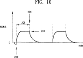
図10は、図1の換気装置の圧力調節換気(PCV)モードでの気道圧と時間との関係を示すグラフである。
図11は、図1の換気装置の持続陽圧気道圧および圧力調節換気を用いる呼吸同期性間欠的強制換気(SIMV−CPAP−PCV)モードでの気道圧と時間との関係を示すグラフである。
図12は、図1の換気装置の電気系統を示すブロック図である。
図13は、図1の換気装置の電源系統を示すブロック図である。
図14は、図1の換気装置のユーザインタフェース系統を示すブロック図である。
図15は、一回呼吸量と体長との関係を示すグラフである。
図16は、呼吸頻度と体長との関係を示すグラフである。
図17は、図1の換気装置のPSV時の緩やかな圧力上昇を示すグラフである。
図18は、図1の換気装置のPSV時の中間的な圧力上昇を示すグラフである。
図19は、図1の換気装置の急速な圧力上昇を示すグラフである。
図20a−図20eは、図1の換気装置の動作を示すフローチャートである。
好適な実施形態の詳細な説明
以下、図面を参照するが、図中、同一番号は同じ構成要素を示すものとする。図1は、本発明の好適な実施形態に係る、一般に参照番号30で示す換気装置のブロック図である。換気装置は、空気系統32と、電気系統34と、ユーザインタフェース系統36と、電源系統38と、を含む。各系統について以下に説明する。
図2は、図1の換気装置の空気系統32を示す。空気系統32は、主用換気装置サブシステムと、バックアップ用換気装置サブシステムと、を含む。各サブシステムについて以下に説明する。
動作時には、一方向チェック弁42の入口でガス供給装置40から空気系統32にガスが供給される。ガスは空気、純粋酸素、またはこれらの混合物でもよい。ガス供給装置40は、最低、ガスをシステム(空気系統)中に送り込むのに十分なだけの圧力でガスを送り、システムの空気系部分を作動させて患者にガスを供給する。チェック弁42は、ガス流を空気系統32へ入れるだけで、ガス供給装置40へは戻らないようにする。
所望の他のガスを供給するためには、本明細書に記載する換気装置を変形してもよい。このような変形は、換気装置設計分野の当業者であれば、本明細書の説明から容易に理解できると考える。
ガス供給はチェック弁42を通り、入力された供給圧を調節して安定レベルに下げる精密調節器44に入る。調節器44は、病院環境の各場所ごとに入力供給が異なるため必要である。図2の実施形態では、調節器44は、調節器から出るガス圧を約40ポンド/平方インチ・ゲージ(psig)に調節するよう動作する。
調節されたガス供給は、その後、ガス圧とガス流量とを安定化するプレナム(plenum)46を通過する。圧力および流量の変動は換気装置30の動作に影響し、患者に悪影響を与えうる。プレナム46の容積は、圧力のばらつきを減衰し、予想ピーク流量需要に応えるだけのガス容量を確保できる程度に大きく選択しなければならないが、ただし必要空間を減じられる程度に小さくなければならない。図2の実施形態では、プレナム46の容積は約1リットルである。
プレナム46には圧力変換器48が接続できるように栓を設ける。圧力変換器は、プレナム46中の圧力を示す図12の換気制御ボード222への入力信号を生成する。プレナム46中の圧力が低すぎると、図12の換気制御ボード222上のマイクロプロセッサがユーザインタフェース制御ボード218に信号を送り、アラーム238を鳴らしてユーザにプレナム46上流で問題が発生したことを知らせる。同様に、圧力が高すぎる場合もアラームが鳴る。
プレナム46は2本の別個の出力ライン50,52を有する。各出力ライン50,52にはガスが連続して供給される。第1の出力ライン50はBUV動作、CPAP動作用にガスを供給し、気道圧検知用のガスを供給する。これらの各特徴については以下に詳述する。プレナム46の第2の出力ライン52は、ガスをソレノイド駆動の3方向弁54に送る。
電圧がかけられると、3方向弁54はガスを出力ライン56に送り、出力ライン56は比例流量制御弁(PFCV)58および3方向ソレノイド駆動弁60に入力を与える。3方向弁54が駆動されない場合は、ガスは第2の出力ライン62に供給される。第2の出力ライン62は、図2の点線で囲み一般的に参照番号66で示すBUVサブシステムのセレクタ弁64、スイッチ70および72用のガス供給ライン68、ならびにデマンド弁74にガスを供給する。
PFCV58は、図12の換気装置制御ボード222上のマイクロプロセッサによって制御される。PFCV58はTechnocraft Inc., Palm Bay, Florida設計のものである。
ガスはPFCV58から一方向弁76を通って一次ガス出力ライン78へ流れる。一次ガス出力ライン78は患者呼吸回路80へガスを与える。弁76はBUVの動作中にガス流がPFCV58に戻らないようにする。
一次ガス出力ライン78のタップ(栓)によって、ソレノイド駆動3方向弁82を接続できる。圧力センサ84は弁82の常開出力に接続される。センサ84は、図12の換気装置制御ボード222へ入力信号を送る。この入力信号は、このサイトにおける圧力を求めるのに使用される。
弁82は圧力センサ84のドリフトの補償に使用される。図2の空気系統の実施形態では、圧力センサ84は、毎回、換気装置を使用する前、および動作中に定期的に、大気圧を0に合わせて較正される。
マイクロプロセッサの故障時または停電の場合は、3方向弁54には電圧がかけられないため、通常の開状態に戻り、出力ライン62にガスを供給する。その後、換気はBUVモードで行われる。
BUVモードでは、出力ライン62はセレクタ弁64にガスを送る。セレクタ弁64は、主用換気装置モード動作の間に設定されており、成人用タイマユニット86または小児用タイマユニット88にガスを送る。
セレクタ弁64の設定は次のように行われる。主用電子式換気時に、換気装置の動作が成人への換気に設定されていれば、ソレノイド駆動3方向弁90が一時的に駆動される。その後、出力ライン50から弁90を通ってセレクタ弁64にガスが送られる。このガス供給により、セレクタ弁64は出力ライン62を成人用タイマ86に接続する。
一方、換気装置が小児患者の換気に設定されている場合は、ソレノイド駆動3方向弁92が一時的に駆動される。ガスは出力ライン50から弁92を通ってセレクタ弁64に送られる。このガス供給により、セレクタ弁64は出力ライン62を小児用タイマ88に接続する。
セレクタ弁は、弁90,92の一方を一時的に駆動して設定されると、弁92,90の他方を駆動してリセットされるまで、その設定位置にとどまる。好適な実施形態では、セレクタ弁64はCLIPPARD 302セレクタ弁である。
成人用タイマユニット86および小児用タイマユニット88は、空気力で駆動されるタイマである。バックアップモードでは、セレクタ弁64から供給されるガスは成人用タイマユニット86または小児用タイマユニット88のいずれかを駆動する。
成人に換気を行う場合、タイマユニット86で決定される間隔で、ガスが供給されて弁70を開く。弁70が開くと、ガスは、出力ライン62から続く供給ライン68から弁70を通ってチェック弁94に流れ、そこから供給ライン96へ送られる。
または、バックアップ換気時に小児患者に換気を行う場合は、小児用タイマ88は選定された間隔で弁72にガスを送り、ガスは供給ライン68からチェック弁98に流れ、そこから供給ライン96へ流れる。
ガス供給ライン96は、ガスをニードル弁100および弁60に送る。ニードル弁100は、バックアップ用換気装置出力ライン102へのガス流量を決定し、そこから一次ガス出力ライン78を通って呼吸回路80へ続く。ニードル弁100は主換気モード中に調節され、その後、もし換気装置がバックアップ換気モードで動作させられると、バックアップ換気モード動作以前の一番最後の設定を維持する。
ニードル弁100の調節は次のように行う。換気装置が主換気モードで動作する場合、図12の換気装置制御ボード222中のマイクロプロセッサで制御されるステッパモータ104がニードル弁100を調節する。ニードル弁100の初期設定は、患者の体長を用いて一回呼吸量を求めるアルゴリズムに基づく。このアルゴリズムについては以下に詳述する。
デマンド弁74には、患者デマンド弁インタフェース108が設けられる。換気装置が主換気モードで動作中は、供給ライン110に与えられるガスがデマンド弁74を閉位置に維持し、デマンド弁74の動作を阻止する。バックアップモードでは、供給ライン56,110を介してガスが供給されないため、デマンド弁74は動作できる。
バックアップモードで動作中、患者のガス需要が、換気装置が与える量を上回ることがある。患者の需要がバックアップ用換気装置サブシステム66から供給されるガスの量を上回ると、デマンド弁74が開き、ガスが出力ライン62から別個の供給ライン106を通って患者まで、直接流れるようにする。
次に、呼気弁充填サブシステムの動作を、まずバックアップ換気モードの動作時、続いて主換気モードの動作時について説明する。
上記のように、バックアップモードで作動中は、ガスは選択された間隔で供給ライン96に供給され、ソレノイド駆動3方向弁60常開ポートに供給される。ガスが供給ライン96に供給されると、ガスは弁60を通って迂回弁112へ進む。これにより、迂回弁112が、呼気弁充填ライン114を迂回弁供給ライン116に接続する。好適な実施形態では、迂回弁112はCLIPPARD 305弁である。
バックアップ用換気装置サブシステム66によって供給ライン96に供給されたガスは、ニードル弁118によって減圧され、精密調節器120によって調節される。通常の換気動作では、回路中にチェック弁122が設けられ、ガスが供給ライン96に戻るのを防止する。ガスはニードル弁124によって再度、減圧され、迂回弁供給ライン116を通って迂回弁112に送られ、ここで迂回させられて呼気弁充填ライン114に進む。
ガスが供給ライン116から呼気弁充填ライン114に送られる間、呼気弁126は閉状態のままであり、これにより主用供給ライン78のガス流が患者に届く。
次に呼気弁126の動作を説明する。吸気時には、PFCV58はガス流を一次ガス供給ライン78を通じて患者128に送る。ガスが患者128に送られている間、呼気弁充填ライン114にもガスが送られ、気嚢(ブラダ:bladder)130を膨張させて呼気弁126の呼気ポート132を遮断する。
BUVモードでは、供給ライン96に与えられるガスは、患者128にガスを供給し、かつ迂回弁112を駆動して呼気充填ライン114にガスを送る。これら2つの機能は空気力的に接続されている。
主換気モードでは、換気装置制御ボード222のマイクロプロセッサは比例流量制御弁58とソレノイド駆動弁60との両方を制御する。マイクロプロセッサは、ガスが一次ガス供給ライン78に供給されている間は、弁60を駆動して呼気ポート132を閉じる。
呼気が必要とされる場合は、換気装置制御ボード222のマイクロプロセッサが弁60をオフするため、またはバックアップ用換気装置サブシステム66が供給ライン96へのガス供給を停止するため、呼気弁充填ライン114へのガス供給が停止する。呼気弁充填ライン114へのガス供給が停止すると、気嚢130が収縮し、患者128は呼気ポート132から呼気を行うことができる。
供給ライン96へのガス供給が停止すると、迂回弁112が切り換わり、供給ライン116を呼気弁充填ライン114から切断する。迂回弁112の切り換えを迅速に行うためにクイックリリース弁134が設けられる。クイックリリース弁134の入力供給ライン136側の圧力が出力供給ライン138側の圧力より高い間は、弁134は閉じたままである。入力供給ライン136側の圧力が出力供給ライン側の圧力をわずかに下回るようになる、つまり供給ライン96上のガス流が停止すると、クイックリリース弁134が開き、供給ライン138に迅速にガスを送り込み、迂回弁112を切り換える。
主換気モード動作の間、弁60には供給ライン56を介してガスが与えられる。図12の換気装置制御ボード222のマイクロプロセッサが弁60を駆動すると、迂回弁112にガスが流れ込み、回路はバックアップモード動作について上記で説明したのと同じように動作する。このとき供給ライン116に与えられるガスは、ニードル弁140を通過する。BUV動作の間、供給ライン56にガスが戻らないようにチェック弁142が設けられる。
呼気弁充填ライン114上のタップに接続されるオリフィス144は、外気中へシャント(分流)されている。オリフィス144は、呼気弁充填ライン114中の圧力が大気圧を上回る場合は、ガスを放出し続けて圧力を下げる。
自発換気時は、肺は肺を覆っている流体のために呼気が行われても完全には収縮しない。しかし、怪我や病気のために患者がこのコーティングを生成できなくなる場合があり、このため持続陽圧気道圧(CPAP)を与えて肺が完全に収縮してしまうのを防止する必要または要請が生じる。
本発明の換気装置では、主換気モード動作時およびバックアップ換気モード動作時に、呼気弁充填ライン114上にCPAPがかけられる。CPAPを望む場合、出力供給ライン50にガスが供給され、ニードル弁146を通って一体型ベンチュリ管(イジェクタまたはジェットポンプとも呼ばれる)148に送られる。主換気モード時には、図12の換気装置制御ボード222のマイクロプロセッサによって制御されるステッパモータ150が、ニードル弁146を調節して、一体型ベンチュリ管148へのガス供給の制御を行う。
ニードル弁146から一体型ベンチュリ管148へのガス供給によって、外気が一体型ベンチュリ管148から供給ライン152へ流入する。呼気時に呼気弁充填ライン114に接続される供給ライン152は、予め設定されたCPAPレベルで気嚢130に連続的にガスを供給する。このためCPAPがかけられている間は、患者128は予め設定されたCPAPレベルまでだけ呼気ができる。
マイクロプロセッサの故障または停電が発生し、換気装置がバックアップモードに切り替わると、ニードル弁146は、換気装置がバックアップモードに切り替わる前に最後に入力された設定を維持する。
空気系統にはまた、気道圧検知ライン154が設けられる。圧力検知ライン154はタップ156で呼吸回路80に接続される。圧力検知ライン154はまた、3方向ソレノイド駆動弁158に接続できるタップを含む。ソレノイド駆動の3方向弁158の共通出力に接続される圧力センサ160は、患者の気道圧を求めるのに使用される。
弁158は圧力センサ160のドリフトの補償のために使用される。図2の空気系統の実施形態では、圧力センサ160は、換気装置の毎回使用時前、および動作中に定期的に、大気圧を0に合わせて較正される。
本発明の換気装置は、CPAP動作時、PCV動作時、またはPSV動作時のうちの少なくともいずれかにおける、呼吸回路80切断時のガス損失を防止するガス節約機能を備える。この機能は、ガス供給に限りがある移動時の換気装置動作時に特に有用である。気道吸引時などに呼吸回路80が換気装置から切断される場合、換気装置はガス流量を増大してCPAP圧を維持しようとするので、大量のガスの無駄が生じうる。
本発明の換気装置では、患者から装置がはずされ、これによって気道圧が低下すると、この圧力変化が圧力変換器160によって検知され、換気装置制御ボードのマイクロプロセッサに通知される。この圧力変化に応じて、マイクロプロセッサはユーザインタフェースボード218にアラーム238を鳴らさせ、ソレノイド駆動弁60およびPFCV58を作動させて、短期間のガスバースト(噴出)を生じさせ、いずれかのバーストを行っている間に圧力上昇が起こるまでこれを続行する。この機能により、移動中に使用する圧縮ガスシリンダの寿命を大幅に延長することができる。
気道圧検知ライン154には、供給ライン50からニードル弁162を通って小流量のガスが与えられる。このパージ流量は、気道圧検知ライン154を閉塞しないようにしておくために与えられる。
図2の空気系統の好適な実施形態では、PFCV58は9つの換気モードの1つでガス供給を出力するよう動作しうる。かかる換気モードについて図3〜図11を参照して説明する。
図3に示す第1の換気モードは、調節機械換気(CMV)である。CMVモードでは、換気装置は、患者側の自発努力とは無関係に、事前選定された換気レート(呼吸数)、一回呼吸量(tidal volume)、および吸気流量で動作する。形成されるピーク膨張圧164は、コンプライアンスに反比例し、抵抗に正比例して変化する。
図4に示す第2の換気モードは、呼気終末陽圧を用いる調節機械換気(CMV−PEEP)である。CMV−PEEPモードでは、換気装置は、ピーク膨張圧166で陽圧呼吸を生じさせ、その後、気道圧は事前に選定した陽圧プラトー168まで下がるが気道圧は0には復帰しない。
図5に示す第3の換気モードは、持続陽圧気道圧(CPAP)である。CPAPモードでは、陽圧気道圧170は、自発換気中連続的に維持される。このモードでは、患者は機械的換気補助を受けない。
図6に示す第4の換気モードは、呼吸同期性間欠的強制換気(SIMV)である。SIMVモードでは、患者は所望通りに自発的に呼吸でき、機械的膨張は事前に選定された間隔で行われる。SIMVレートは換気レートである。SIMV呼吸172同士の間に、患者は換気装置のPFCV58から自発的に吸気174および呼気176を行う。
図7に示す第5の換気モードは、持続陽圧気道圧を用いる呼吸同期性間欠的強制換気(SIMV−CPAP)である。SIMV−CPAPモードでは、患者は事前に選定したCPAPレベル178で所望通りに自発呼吸できる。SIMV呼吸180同士の間に、患者は換気装置のPFCV58から自発的に吸気182および呼気184を行う。このモードでは、SIMV呼吸180は事前に設定した間隔で行われる。
図8に示す第6の換気モードは、圧力補助換気(PSV)である。PSVモードでは、換気装置は患者によって「オン」186にされ、事前選定した陽圧目標値になるまで吸気フェーズを続ける。患者の努力が続く間は、事前選定した気道圧は一定値188に維持され、この間、換気装置からのガス流量190は変化する。患者の吸気流量が初期ピーク機械吸気流量の所定割合192まで下がると、吸気サイクルは「オフ」にされる。換気装置の流量はこのようなサイクルで変化し、その後、受動呼気が発生する。PSVでは、ピーク吸気流量、流量波形、一回呼吸量、および気道圧の曲線は、患者の呼吸パターンによって変化する。一回呼吸量は、PSVレベル、患者の吸気努力、トータルコンプライアンス、およびトータル抵抗から決定される。
図9に示す第7の換気モードは、持続陽圧気道圧および圧力補助換気を用いる呼吸同期性間欠的強制換気(SIMV−CPAP−PSV)である。SIMV−CPAP−PSVモードでは、事前設定した定期的な間隔でSIMV呼吸194が与えられる。SIMV呼吸194同士の間の自発的に開始される呼吸の際に、患者はPSV196,198を受ける。SIMV呼吸およびPSV呼吸の呼気時に、気道圧は事前選定したCPAPレベル200まで下がる。
図10に示す第8の換気モードは、圧力調節換気(PCV)である。PCVモードでは、換気装置は、患者による起動、または時間が来たことによる始動、のうちのいずれか早いほうのタイミングで「オン」202にされ、事前選定した陽圧限界204まで吸気状態を続ける。患者の努力が続行する間は、事前選定した気道圧は一定204に維持され、この時、換気装置からのガス流量は変化する。事前選定した吸気時間208が経過すると、吸気サイクルは「オフ」206にされる。換気装置はこのようなタイムサイクルで動作し、その後、受動呼気が発生する。PCVでは、ピーク吸気流量、流量波形、一回呼吸量、および気道圧の曲線は、患者の呼吸パターンによって変化する。一回呼吸量は、PCVレベル、患者の吸気努力、トータルコンプライアンス、およびトータル抵抗から決定される。
図11に示す第9の換気モードは、持続陽圧気道圧を用いる圧力調節換気(PCV−CPAP)である。PCV−CPAPモードでは、上述したPCVモードで陽圧呼吸210,212が与えられる。PCV呼吸の呼気の間、気道圧は事前選定したCPAPレベル214まで下がる。
図1の実施形態の換気装置では、最小限の機能を有する移動時用換気装置として作動するように、上述のモードのうちのいくつかを不能化することができる。特に、基本モードでは、換気装置はSIMV−CPAPモードでのみ作動する。このモードで設定されるCPAPの上限は、通常許容可能なCPAPレベルよりもかなり低い。図1の換気装置の実施形態では、CPAPレベルは、陽圧が0ないし5水柱センチメートル(cmH2O)の範囲にあるように調整することができる。
アドバンストモードでは、上述の9つのモードの各々で換気を行うことができる。アドバンストモードでのCPAPの上限は、ベーシックモードで許容される上限よりもかなり高く設定することができる。図1の換気装置の実施形態では、陽圧が0ないし30cmH2Oの範囲にあるようにCPAPを調整することができる。
図1の実施形態の換気装置の図12の電気系統216は、ユーザインタフェースシステムと、電源システムと、換気制御システムとからなる。
ユーザインタフェースシステムは、ユーザインタフェース制御ボード218と、LCDドライバを含むユーザインタフェース表示ボード220と、数字およびグラフィックLCD表示装置236と、アラームインジケータ238と、スイッチ240と、多目的ダイヤルとを含む。
電源システムは電源を含み、バッテリ充電器ボード224は、換気装置の電子制御系および電気制御式空気系が必要とするすべての電力をライン226を介して供給する。電源は、バッテリー228から、またはACもしくはDC外部電源230から供給される。電源システムは、世界中で利用される広範囲のAC電源で作動できる必要がある。
換気装置制御ボード222は、換気装置の作動ロジックすべてを制御する。したがって、換気装置制御ボード222は、比例流量制御弁58と、ソレノイド駆動弁54、60、82、90、92および158(図12では包括的に242で示される)と、圧力変換器48、84および160(図12では包括的に244で示される)との作動と、バックアップ用換気装置66の設定と、を制御する。
換気装置の電気系システム216は、ウォッチドッグ(監視)/リセットライン232、234を介して、電源および充電器ボード224と通信して、一般的なウォッチドッグ制御回路を実現する。電源ボード224はマイクロプロセッサを含み、このマイクロプロセッサは、電力供給レベルをモニタし、ユーザインタフェース制御ボード218と換気装置制御ボード222とがウォッチドッグタイマを適切にリセットしていることを確認する。電力供給が許容範囲を超えた場合、または換気装置制御ボード222もしくはユーザインタフェース制御ボード218のいずれかがタイムアウトインターバルまでにウォッチドッグをリセットしていない場合、電源および充電器ボード224のマイクロプロセッサは、電気系統216への電力を遮断し、バックアップ換気モードに切り替える。
図13の電源サブシステム38は電源モニタ248を含み、この電源モニタ248は、バッテリー228の電圧、電流、および温度と、5ボルト電源250、+12ボルト電源252、および−12ボルト電源254の電圧とをモニタし、バッテリー228またはDC出力250、252、254のいずれかが正常許容範囲から外れると、状態インジケータ(指示信号)を生成する。
バッテリー充電器256は、バッテリー228の充電を行うと同時に、換気装置を作動させる。バッテリー充電器256はまた、バッテリー228をモニタするモニタを含み、バッテリーの残留容量を示す信号をマイクロプロセッサ258に与える。
電源および充電器ボード224は、電源サブシステム38にサービスする際に用いられるデバッグポート260を含む。
図14のユーザインタフェース系統36は、マイクロプロセッサ262と、EPROM264と、RAM266と、キーボードロジックデバイス268と、光学ポテンショメータロジックデバイス270と、マイクロスーパバイザ272と、デバッグ端末274と、多目的ダイヤル276とを含む。
ユーザインタフェース制御ボード218のマイクロプロセッサは、シリアル・マルチプロセッサ通信ライン246を介して換気装置制御ボード222と通信する。たとえば、巡回冗長符号等を用いて、各制御ボードにおいて受信情報のエラー検出を行う。不良なデータブロックの再送信を扱うのには単純なACK/NAKプロトコルを用いることができる。
図12のユーザインタフェース表示ボード220は、現在の換気装置の設定、メッセージ、アラームの表示を制御し、ユーザーがこれらの設定を変更することを可能にする。図1の実施形態では、一回呼吸量、レート(呼吸数)、流量、感度、CPAP、PSV/PCV、体長、PIP、高圧アラーム、低圧アラームに対して、それぞれ個別に数字LCD表示236が設けられる。吸気時間と吸気呼気(I:E)比とに対しては、共通の表示装置が用いられる。
図1の実施形態の換気装置に設けられる可聴アラームは、無呼吸、高圧、低圧、切断、圧力変換不良、およびI:E比に対する警告のアラームを含む。
図12のユーザインタフェース制御ボード218は、ユーザインタフェース系統サブシステム36にサービスするのに用いられるデバッグ端子274を含む。
ユーザインタフェース制御ボード218はまた、患者の体長に基づいて一回呼吸量、レート、流量、およびI:E比の初期パラメータを設定するためのアルゴリズムを含む。さらに、ユーザインタフェース制御ボード218は、患者の体長に基づいて、換気パラメータ限界値、PSV体積限界値、およびアラームを自動的に設定する。
従来から、換気装置における一回呼吸量の設定は、患者の除脂肪体重(lean body weight)に基づいている。一般的な状況では、一回呼吸量は、除脂肪体重の1キログラム(kg)あたり体積10ミリリットル(mL)の割合で計算される。
一回呼吸量を適切に設定するためには、機械換気の前に患者の体重を測定しなくてはならない。しかし、臨床の実務において、特に緊急事態で、患者の体重を測定することは困難、または不可能であるため、これらの状況では、除脂肪体重を推定しなくてはならない。体重が容易に測定できる場合でも、一回呼吸量は患者の全体重ではなく除脂肪体重に基づくため、除脂肪体重を推定することが要求される。除脂肪体重の推定における誤差は、膨張不足(hypoventilation)または過剰膨張(hyperventilation)につながるおそれがあり、後者は気圧性肺障害(pulmonary barotrauma)を起こしやすい。
同様に、換気レートも、ある面では、臨床医の技量に基づいて主観的に推定される。一分換気量(minute ventilation)は一回呼吸量と換気レートとを乗じたものに等しいため、換気レートの設定が不適切であれば、換気レートの不適切な選択、ひいては一分換気量の不適切な選択につながる可能性があり、換気不足または過剰換気となるおそれがある。さらにこれは呼吸性酸塩基障害(respiratory acid-base disturbances)や生理学的機能不全につながり得る。
呼吸不全の患者を治療した経験の少ない未熟な臨床医は、換気装置を不適切に設定するリスクが高く、上述の問題につながってしまう。これに対するより安全な手法は、特に未熟な臨床医が換気装置を用いる場合には、一回呼吸量と換気速度とを客観的な基準に基づいて設定することである。
機械換気を受ける麻酔した無呼吸の患者についての研究において、体長および体表面積が、一回呼吸量の予測因子として、除脂肪体重に匹敵することがわかった。さらに、体長および体表面積は、除脂肪体重よりも優れた換気レートの予測因子となることがわかった。
図15において、体長の関数として、対象とした95人の患者の理想的な一回呼吸量の設定を表すデータ点278をプロットしたものが示される。これらのデータ点から多項式回帰分析を行って、このデータに最もよく適合する多項式回帰直線280を得た。この分析結果を以下の表1に示す。

一回呼吸量(L)=0.21+0.0037X+0.0000108X2
同様に、図16には、体長の関数として、対象とした95人の患者の理想的な換気レート(呼吸数)を表すデータ点282をプロットしたものが示される。多項式回帰分析から得られる、このデータに最もよく適合する多項式回帰直線284を決定するのに用いたデータを、以下の表2に示す。
レート(呼吸/分)=40.59−0.36X+0.000996X2
体長、体表面積、および体重の各々から一回呼吸量と換気レートを十分に推測する生理学的予測可能性を求めるのに、相関予測分析法を用いた。r2の値が0.64ないし0.81の範囲にある場合に良好な生理学的予測可能性が見られた。
体長の関数としての一回呼吸量と換気レートのr2の値は、それぞれ0.71と0.74であった。体表面積の関数としての一回呼吸量と換気レートのr2の値は、それぞれ0.74と0.71であった。体重の関数としての一回呼吸量と換気レートのr2の値は、それぞれ0.73および0.62であった。
r2の計算より、一回呼吸量を決定するために体長または体表面積を用いることによって、体重を用いてこれを決定するのに匹敵する結果が得られることがわかった。r2の値は、体長と体表面積とが、体重よりも優れた換気レートの予測因子となることを示している。
本発明の換気装置においては、一回呼吸量と換気レートの初期設定を計算するのに体長を用いているが、これは、体長は体表面積よりも簡単に求められる点で明らかに利点があるからである。
基本モードで作動している際には、体長を求め、それをオペレータが図12のスイッチ240を介して入力する。この情報は、体長から一回呼吸量と換気レートを計算するための多項式を表すアルゴリズムがプログラミングされたソフトウェアに与えられ、このソフトウエアはその情報を用いて一回呼吸量と換気レートの初期設定値を決定する。
体長をマニュアルで入力する場合について本発明を説明しているが、本発明によって、この情報を自動的に決定および入力するための機構を有する換気装置を実現することも可能である。たとえば、患者の体長を測定するのに、超音波測定装置やレーザー、電子ポテンショメータに接続される内蔵テープリール等を用いてもよい。
体長に基づいた一回呼吸量および換気レートの設定に加えて、諸々の換気パラメータの限界値も患者の体長に基づくものである。従来の換気装置では、未熟なユーザーが、PSVおよびPCVモードの圧力レベル等の換気パラメータをその患者に対しては高すぎる値に設定する可能性があった。患者の体長に基づいて換気パラメータの限界値を決定するアルゴリズムを組み入れることによって、これらの潜在的に危険な状況を回避することができる。同様に、図1の実施形態の換気装置において、換気装置制御ボード222には患者の体長に基づいて換気アラームを設定するためのアルゴリズムがプログラミングされている。
機械換気を行う際には、換気パラメータが適切であることが不可欠である。本発明の換気装置には、不適切な換気パラメータを用いて図2のバックアップ用換気装置サブシステム66が作動するのを防止するためのロックアウト機構が設けられる。
不適切な設定を用いた換気装置の作動は、ガス供給装置および電源から切断されている状態の後、電源が接続される前にガス供給装置が換気装置に接続された場合に起こり得る。この状況で、前の患者に対する使用の際に設定されたバックアップ用換気装置のパラメータが残っていれば、バックアップ用換気装置はこれらのパラメータを用いて作動することとなる。
バックアップ用換気装置のロックアウト機構を用いれば、ユーザーが換気装置をオフにすると、換気装置制御ボードのマイクロプロセッサがステッパモータ104を作動させて、ニードル弁100を遮断する。換気装置が移動され、電源が接続される前にガス供給装置がその換気装置に接続されると、バックアップ用換気装置は作動はするが、ガスをバックアップ用換気装置出力ライン102に供給することができない。
さらに、停電になってバックアップ用換気装置の作動が起こった後、換気装置が、電源を復旧させる前に切断される可能性もある。この場合、主用およびバックアップ用換気装置の設定は、前の患者のもののままである。
この状況では、ロックアウト機構は、換気装置をバックアップモードから主換気モードに切り替える前にたどらなくてはならない確認シーケンスの形態で実現される。このロックアウト機構により、ユーザーは、換気装置が主換気モードに戻るよう切り替えられる前に、停電前と同じ患者に接続されていることを確認するよう求められる。
電源が復旧され、換気装置がオンにされると、図12のLCD表示装置236と可聴アラーム238とにより、ユーザーは、換気装置が停電前と同じ患者に接続されていることを確証する情報をスイッチ240を介して入力するよう促される。この情報は換気装置制御ボード222のマイクロプロセッサに伝送され、このデータを用いて、換気装置が主換気モードに戻るように切り替えられ得るかどうかが判定される。
換気装置制御ボード222のマイクロプロセッサが、入力された情報から、換気装置がもう同じ患者には接続されていないと判断すると、主換気モードは不能化されたままとなり、流れをゼロにすることによってBUVが不能化され、換気装置制御ボード222のマイクロプロセッサは、ユーザーに、新しい体長をインタフェース制御ボード218に入力するよう指示する。
本発明の換気装置に含まれる改良点は、圧力補助換気中の上昇率(上昇速度:rate of rise)を適応的に設定できることである。圧力補助換気中の患者の呼吸仕事(work of breathing:WOB)と圧力上昇率との相関が確認されている。
WOBは圧力の上昇に反して変化し、上昇率が高くなるほどWOBは低くなり、逆に、上昇率が低いほど、WOBは高くなることがわかった。
吸気圧の上昇率が図17の低い上昇率286から図18の中間上昇率288へと増すにつれて、WOBの減少が見られる。同様に、圧力の上昇率が図19の矩形状波290の上昇率に近づくと、換気装置の出力は、吸気圧によりよく一致し、その結果、WOBが減少する。
最適な圧力上昇率、従って最小のWOBに達するのは、上昇率が患者の肺の力学的構造(pulmonary mechanics)に一致するときであることがわかった。本発明の好ましい実施形態の換気装置ユニットは、PSVモードが起動されたときに上昇率を適応的に設定することで、この発見を利用するものである。
換気装置は5つの異なる圧力上昇率を評価し、リンギングが最小の矩形圧力波形となるような上昇率を選択する。
ここに包含されるもののいずれに関しても、本発明を5つの上昇率の使用に限定するものではないことを理解されたい。本発明による換気装置ユニットにおいていかなる数の上昇率を用いることもできると考えられる。
図1の好ましい実施形態には、周囲の圧力における変化を検出するための、一体型の気圧変換器が含まれる。周囲に大きな圧力の変化が起こると、換気装置制御ボード222のマイクロプロセッサは、これを補償するべく、PFCV弁58の開口を広げたり、狭めたりし、それによって、選択された一回呼吸量を適切に維持し、周囲の圧力による変化を補う。これは、たとえば、ルックアップテーブルやアルゴリズムを使用することによって行われる。
図1の換気装置の制御ソフトウエアについて、図20a〜20eを参照して説明する。
図20aにおいて、本システムの制御は、換気装置の初期化292による動力(電力)供給開始(power up)により開始される。換気装置の初期化292において、圧力変換器48、84、160は指示値を0に初期化され、BUVニードル弁100は閉じられ、CPAPは0にセットされ、患者の体長が入力され、その体長に基づき換気装置のパラメータがセットされる。
初期化292に続き、換気装置は呼気初期化(exhale initialization)294を実行する。このステップで、図2の一次ガス供給ライン78へのガスの流れが遮断され、呼気弁126が開かれる。呼気初期化294において、ピーク吸気圧と一回呼吸量とを含む呼吸パラメータがリセットされる。潜在的無呼吸症状の発現を識別するために用いられる無呼吸タイマカウンタは、呼吸初期化294においてリセットされる。アラーム条件の存在を確認するテストも、呼気初期化294において行われる。
呼気初期化294に続き、ユーザインタフェースボードに対し、新たな入力を求めてポーリング296が行われる。新たな入力があれば、入力ルーチン298が実行され、その入力ルーチンにおいて、換気装置のパラメータがその新たな入力に基づきセットされる。新たな入力が行われた場合、あるいは新たな入力が存在しない場合には、無呼吸タイマカウンタのインクリメント300が行われ、その無呼吸タイマカウンタのカウント値と予め選定された無呼吸限界との比較302が行われる。
無呼吸タイマカウンタのカウント値が無呼吸限界を超えた場合は、304で、無呼吸アラームが鳴り、無呼吸バックアップ換気が開始される。無呼吸バックアップ換気の間は、患者が自発呼吸を始めるか、換気装置のパラメータがリセットされるまで、強制的なIMV呼吸が行われる。
無呼吸タイマカウンタが無呼吸限界を超えていない場合は、換気装置は、306で患者の自発呼吸を存在を確認する。このあと、PCV、SIMV、CPAP及びPSVの4つの換気タイプについての判断を行う1組の条件ステップが行われる。
306において自発呼吸が確認され、かつ308においてPCVモードがオンであった場合は、図20bのPCV初期化320が行われる。逆に、306で自発呼吸が確認され、かつ308でPCVモードがオフであり、かつ316でSIMV呼吸が行われていない場合は、図20cのSIMV初期化352が行われる。
同様に、306で自発呼吸が確認されず、かつ310において呼吸を施すべき時間になっており、かつ312においてまだ呼吸が施されておらず、かつ314でPCVモードがオンの場合は、図20bのPCV初期化320が行われる。306で自発呼吸が確認されず、かつ310において呼吸を施すべき時間になっており、かつ312においてまだ呼吸が施されておらず、かつ314でPCVモードがオフの場合は、図20cのSIMV初期化352が行われる。一方、310で呼吸を施すべき時間ではないと判定されるか、312で呼吸が既に施されたと判定された場合は、制御の流れは、新たな入力のチェック296に戻る。
306で自発呼吸が確認され、かつ308でPCVモードがオフであり、かつ316でSIMV呼吸が既に施されており、かつ318でPSVモードがオフの場合は、図20dのCPAP初期化364が行われる。逆に、306で自発呼吸が確認され、かつ308でPCVモードがオフであり、かつ316でSIMV呼吸が既に施されており、かつ318でPSVモードがオンの場合は、図20eのPSV初期化378が行われる。
図20bのPCV初期化320において、図2の呼気弁126が閉じられ、初期流量がセットされる。加えて、PCV換気の間は圧力が調節されなければならないので、所望の圧力を維持するために必要な流量が、比例積分微分(PID)コントローラにより求められ、セットされる。圧力調節は以上のようにしてなされる。なぜなら、圧力は直接的に調整することができない代わりに、流量を変化させることにより調整されるからである。
PCV初期化ステップ320に続き、PCV上昇率(PCV rate of rise)の選択322が行われる。適切なPCV上昇率を選択する間、現在の圧力上昇率を維持するよう、流量がPIDコントローラに基づき調整される。更に、最大初期流量が計算される。
それから、圧力検知ライン154のチェック324が行われ、そのラインに圧力があるかどうか調べられる。このチェックで、圧力フィードバックがなかった場合は、非接続状態と識別され、アラームが駆動され、換気装置はガス節約モードの動作326を開始する。ガス節約モードの動作326においては、圧力が検知されるまで、前記検知ライン内の圧力のモニタ328が行われる。圧力検知ライン154内の圧力が検出され、かつ換気装置がガス節約モードで作動している場合は、呼気初期化294が実行される。
PCV上昇率ステップ322に続き、324で圧力検知ライン154内で圧力が検出された場合は、呼吸時間(breath time)が吸気時間(inhalation time)を超えたか否かの判定330を行う条件ステップが実行される。330で呼吸時間が吸気時間を超えた場合は、呼気初期化294が実行される。330で呼吸時間が吸気時間を超えなかった場合は、その圧力がピーク吸気圧(PIP:peak inspiratory pressure)を超えたか否かの判定332を行う次の条件ステップが実行される。
PIPアラームは、換気装置がPCVモードで作動している間、高圧用アラームとして動作する。332で前記圧力がPIPアラームレベルを超えた場合、呼気初期化294が実行される。PIPアラームレベルを超えなかった場合は、一回呼吸量が最大許容一回呼吸量を超えたか否かの判定334のための条件ステップが実行される。もし一回呼吸量が最大許容一回呼吸量を超えた場合は、呼気初期化294が実行される。
最大許容一回呼吸量を超えなかった場合は、圧力検知ライン154内の圧力がPCVレベルの90%を超えたか否かの判定336のための条件ステップが実行される。その圧力がPCVレベルの90%を超えなかった場合は、PCV上昇率ステップ322に戻る。336で圧力検知ライン154の圧力がPCVレベルの90%を超えた場合は、PCV換気338が実行される。
PCV換気338においては、PCVレベルを維持するために、PIDを用いて流量が調節される。PCV換気においては、圧力検知ライン154が圧力フィードバック340のためにチェックされる。ここで圧力が検出されなかった場合は、非接続状態が検出され、換気装置はガス節約モード動作342を開始する。ガス節約モードで動作中の間も、圧力検知ライン内の圧力のモニタ344が行われる。ここで圧力検知ライン154内の圧力が検出されない間は、換気装置はガス節約モード342を維持する。圧力検知ライン154内に圧力が検出されると、呼気初期化294が実行される。
PCV換気338において、340で圧力検知ライン154内に圧力が検知された場合は、PCV換気をいつ終了するかを決定するための条件ループが実行される。通常の状態では、PCV換気は、予め設定された時間の間持続し、その結果、前記条件ループの一部として、呼吸時間(breath time)がモニタされ、呼吸時間が吸気時間を超えたかの判定346が行われる。吸気時間を超えた場合には、呼気初期化294が行われる。
吸気時間を超えなかった場合は、348で、圧力検知ラインの圧力が、高圧用PIPアラームを超えないよう、モニタされる。PIPアラームを超えた場合は、呼気初期化294が行われる。その圧力がPIPアラームを超えなかった場合は、350で、一回呼吸量が、最大許容一回呼吸量を超えないよう、チェックされる。最大許容一回呼吸量を超えた場合は、呼気初期化294が実行される。最大一回呼吸量を超えなかった場合は、PCV換気338が続行される。
最初の6回のPCV呼吸の間、5つの異なる上昇率が利用され、各上昇率において2回呼吸が行われる。最初の10回のPCV呼吸ののちに、PCV波形が目標波形と比較される。10回目のPCV呼吸に続き、これまでの10個のPCVオーバーシュート値から、最良の上昇率が決定される。この上昇率は、その後の更なるPCV換気の間に用いられる。
図20cのSIMV初期化352においては、呼気弁126が閉じられ、流量が一定値にセットされる。その後、354でSIMV呼吸が施される。SIMV呼吸においては、圧力検知ライン154の圧力のチェック356が行われる。ここで、圧力がなかった場合は、358でアラームが起動され、換気装置はSIMV換気を続行する。
SIMV換気354の間、360で、SIMV時間を超えないよう、換気時間がチェックされる。さらに、362で、限界値を超えないよう、圧力検知ラインの圧力がチェックされる。換気時間がSIMV時間を超えるか、圧力検知ラインの圧力が前記限界値を超えるかすると、呼気初期化294が実行される。
図20dのCPAP初期化364においては、無呼吸アラームがリセットされ、PIDコントローラが初期化され、初期流量がセットされる。CPAP換気の間、呼気弁126は、CPAPレベルまで加圧される。そして、呼気弁126からのガスの散逸を最小化するために、CPAP初期化364において、目標圧力がCPAP設定値から0.5水柱センチメートル分低い値にセットされる。
CPAP初期化ステップ364に続き、366でCPAPが行われる。CPAP366の間、流量が、CPAP圧力を維持するよう、断続的に繰り返し調整される。CPAP換気366の間、圧力検知ライン154の圧力のモニタ368も行われる。圧力検知ライン154内の圧力が検出されなかった場合、非接続状態と識別され、370で換気装置はガス節約モードで動作し始める。
換気装置は、372で圧力検知ライン154内の圧力が検出されるまで、ガス節約モード370の動作を続ける。圧力が検出されると、呼気初期化294が行われる。
CPAP換気366の間、366で圧力検知ライン154内の圧力が検出されると、374でその圧力がCPAP圧力を超えるか否か、3サイクルの間モニタされる。3サイクルの間圧力がCPAP圧力を超えず、かつ376の判定で最大CPAP時間を超えていなければ、CPAP366が続行される。一方、374において圧力が3サイクルの間CPAP圧力を超えるか、376で最大CPAP時間を超えるかすると、呼気初期化294が実行される。
図20eのPSV初期化378の間、呼気弁126は閉じられ、初期流量がセットされ、PID値が計算される。PSV初期化378に続き、380でPSV上昇率が制御される。適切なPSV上昇率を選択する間、流量は、PIDに基づきその圧力上昇率を維持するように調整される。更に最大初期流量も計算される。
圧力検知ラインが、その後、382で、そのライン内に圧力があるか否かを判定するためにチェックされる。ここで圧力フィードバックがなければ、非接続状態と認識され、換気装置はガス節約モード動作384を開始する。384のガス節約モードの動作の間、386で、圧力が検出されるまで、検知ライン内の圧力がモニタされる。圧力検知ライン154で圧力が検出され、かつ換気装置がガス節約モード動作384を行っている場合は、呼気初期化294が実行される。
PSV上昇率ステップ380に続き、382で圧力検知ライン154内の圧力が検出されると、388で、呼吸時間が最大吸気時間を超えたか否かを判定する条件ステップが実行される。388で呼吸時間が最大吸気時間を超えた場合は、呼気初期化294が実行される。388で呼吸時間が最大吸気時間を超えなかった場合は、390で、その圧力がピーク吸気圧(PIP)を超えたか否かの判定のための条件ステップが実行される。
PIPアラームは、換気装置がPSVモードで動作している間、高圧用アラームとして機能する。390で、その圧力がPIPアラームを超えた場合は、呼気初期化292が実行される。PIPアラームを超えなかった場合は、392で、一回呼吸量が最大許容一回呼吸量を超えたかを判定するための次の条件ステップが実行される。そして、最大許容一回呼吸量を超えた場合は、呼気初期化294が実行される。
最大許容一回呼吸量を超えなかった場合は、394で、圧力検知ライン154内の圧力がPSVレベルの90%を超えたかどうかを判定する次の条件ステップが実行される。その圧力がPSVレベルの90%を超えなかった場合は、制御はPSV上昇率ステップ380に戻る。394で圧力検知ライン154内の圧力がPSVレベルの90%を超えると、PSV換気396が行われる。
PSV換気396の間、PIDを利用して、流量が、PSVレベルを維持するように調整される。各PSV呼吸のあと、圧力フィードバック398のために圧力検知ライン154がチェックされる。圧力が検知されなかった場合は、非接続状況が検出され、400において換気装置はガス節約モード動作を開始する。ガス節約モード動作400の間、402で圧力検知ラインの圧力がモニタされる。圧力検知ライン内で圧力が検出されない間は、換気装置はガス節約モード400を続行する。402で圧力検知ライン154内に圧力が検出されると、呼気初期化294が実行される。
PSV換気396の間、圧力検知ライン154内に圧力が検知されると、いつPSV換気を中止するかを決定するための条件ループが実行される。普通の状態では、予め設定された圧力までPSV換気が続行される。そして、前記条件ループの一部として、404で、流量がモニタされ、最大流量の25%未満になったか否かが判定される。流量が最大流量の25%未満に落ち込んだ場合は、呼気初期化294が実行される。
404で、流量が最大流量の25%未満まで落ち込んでいない場合は、406で、呼吸時間が最大吸気時間を超えないよう、呼吸時間がチェックされる。呼吸時間が最大吸気時間を超えた場合は、呼気初期化294が実行される。406で呼吸時間が最大吸気時間を超えなかった場合は、408で、圧力検知ラインの圧力が、高圧用PIPアラームを超えないよう、モニタされる。圧力がPIPアラームを超えると、呼気初期化294が実行される。
圧力がPIPアラームを超えなかった場合は、410で、一回呼吸量が、最大許容一回呼吸量を超えないよう、チェックされる。最大許容一回呼吸量を超えると、呼気初期化294が実行される。最大許容一回呼吸量を超えなかった場合は、PSV換気400が続行される。
最初の10回のPSV呼吸の間、5つの異なる上昇率が用意されており、各上昇率において2回呼吸が行われる。最初の10回のPSV呼吸のあと、PSV波形が目標波形と比較される。10回目のPSV呼吸に続き、圧力プロファイルから最良の上昇率が決定される。この上昇率は、その後の更なるPSV換気の間用いられる。
以上では輸送時用の換気装置を例にとって説明したが、以上に説明した各特徴点は、他の換気装置に組み込んだ場合にも同様に有用であることは明らかであろう。上記記載及び図面は、本発明の目的や特徴、メリットを達成するための好適な実施例の一例に過ぎず、本発明がそれら記載等に限定されることを意図するものではない。以下の請求の範囲に含まれる本発明の如何なる変形例も、本発明の一部をなすものである。 Field of Invention
The present invention relates to a ventilation device. More specifically, the present invention relates to a hybrid microprocessor controlled ventilator. The ventilator of the present invention can operate in either a basic mode as a minimally equipped mobile ventilator, or an advanced mode as a fully equipped ventilator used in an ICU when moving, in an emergency, or in an ICU.
Background of the Invention
Ventilation is a physiological process in which gas enters and leaves the lungs, sends oxygen to each organ in the body, and expels carbon dioxide. In spontaneous or unassisted breathing, a negative pressure (lower than atmospheric pressure) is created in the chest and gas enters the lungs. During spontaneous breathing, exhalation is passive.
In medical procedures, it is often necessary to substitute a patient's spontaneous breathing with mechanical ventilation assistance. This is necessary if respiratory failure or the patient is anesthetized.
Mechanical ventilation assistance is performed by moving a known amount of gas to the patient's lungs under positive pressure (any pressure above atmospheric pressure). Alternatively, a negative spontaneous pressure is generated around the thoracic cavity to generate pseudo spontaneous inspiration. Negative pressure (pressure below atmospheric pressure) is often used for mechanical ventilation assistance, but positive pressure ventilation is much more common.
Various attempts have been made to provide a mobile ventilator designed to provide positive pressure ventilation. In such an attempt, the following two types of devices have been produced. (1) A minimally equipped mobile ventilator designed for medical personnel who are not well trained in breathing, operating in a limited number of ventilation modes, and (2) with numerous features, A ventilator that operates in a wide range of ventilation modes and is therefore suitable for use only by medical personnel who are well-trained to breathe. Such prototypes are described in a number of US patents such as:
U.S. Pat. No. 5,211,170 discloses a portable emergency respirator in which airflow is generated by an electrically driven air compressor. The air compressor operates in one of three different modes, each producing three different air outputs.
U.S. Pat. No. 4,941,469 and related U.S. Pat. No. 4,823,787 disclose portable ventilators that provide pressurized air to a patient by a reciprocating pump that is electrically driven and periodically operated. ing. These patented ventilators can operate in a number of ventilation modes.
U.S. Pat. No. 4,905,688 discloses an air-powered portable self-contained ventilation / resuscitation device that uses a solid oxygen generator such as a chlorate candle. This ventilation / resuscitation device is designed for healthcare professionals who are not well trained in breathing, so it has limited features and ventilation modes.
U.S. Pat. No. 4,651,731 discloses a portable self-contained ventilation / resuscitation device using a solid oxygen generator such as a chlorate candle. This ventilator / resuscitation device has a number of adjustable features and various ventilator modes and is intended to be operated by well-trained medical personnel.
Such conventional devices have many disadvantages. Specifically, a minimally equipped ventilator can maintain the breathing of a serious patient, but does not have many advanced equipment that is equipped with a high performance ventilator. Such devices are limited in application because they are only suitable for short-term ventilation that may be necessary when moving.
In contrast, high performance ventilators are generally expensive, large and require more training to operate than minimally equipped ventilators. For this reason, high performance ventilators are impractical in various environments such as aeromedical transport, emergency rooms, inter-hospital transport, and hospitals in developing countries and third world countries.
In prior art devices that use a gas supply controlled by a microprocessor or electrically driven, a power outage may render the ventilator inoperable. Alternatively, prior art devices that are driven or controlled by aerodynamic forces do not have many of the advanced safety and features enabled by the use of the latest microprocessor technology.
Also, with such prior art devices, the health manager can take a tidal volume (VT), Ventilation frequency (f), and inspiratory flow (Vi) Etc. The first parameter must be entered. These values are usually determined from the patient's weight and age. However, in an emergency, it is difficult to accurately determine the patient's weight, and incorrect parameters are input, so the ventilation device may be set incorrectly and possibly dangerous. Prior art devices do not have a safety mechanism to prevent this occurrence.
Summary of the Invention
The present invention relates to a hybrid microprocessor controlled ventilator.
In one embodiment of the present invention, a ventilation device is provided that includes a ventilation flow control device and a controller for adjusting the ventilation flow control device. The controller operates in a first mode that adjusts the ventilation flow controller to ventilate in one of the first set of ventilation modes, or adjusts the ventilation flow controller to adjust the second flow mode set. It can operate in the second mode with one ventilation.
In another embodiment of the present invention, a method for operating a ventilator is provided. In this method, data representing the length of the patient to be ventilated is input to the control device, the first ventilation parameter is calculated based on the input length data, and ventilation is performed according to the calculated first ventilation parameter.
In another embodiment of the present invention, a ventilator is provided that includes a main ventilator subsystem, a solenoid gas supply valve with multiple outputs (modes), and a backup ventilator subsystem. The backup ventilator is connected to the pneumatic actuator, a timing unit connected to the pneumatic actuator and opening the pneumatic actuator at a preselected interval, and an output from the pneumatic actuator connected to the pneumatic actuator. A flow control device. The solenoid gas supply valve supplies gas to the main ventilator subsystem under the first set of operating conditions and supplies gas to the backup ventilating subsystem under the second set of operating conditions.
It is an object of the present invention to have a “basic” mode and an “advanced” mode, which can be operated by a health manager with little breathing training experience, and in the advanced mode, is a well-trained health care professional as a fully equipped ICU ventilator. It is to provide an inexpensive full-featured ventilator unit that can be operated by a person.
Another object of the present invention is to determine the tidal volume (VT), Ventilation respiratory frequency (f), and inspiratory flow (ViIt is to provide a ventilation device having an automatic ventilation setting function that automatically sets an initial value.
Yet another object of the present invention is to provide a ventilator incorporating a parameter tracking independent aerodynamic backup ventilator (BUV). In the event of a power failure or failure of the main electronic ventilator, the ventilator automatically operates in a backup mode that uses only the aerodynamic force and the ventilation parameters set before the failure.
Yet another object of the present invention is to provide a ventilator having an electrical power-independent system for continuous positive pressure airway pressure (CPAP). This control system maintains CPAP at the level prior to a power outage or failure of the main electronic ventilator during BUV operation.
Yet another object of the present invention is to provide a ventilator having a BUV lockout system. The lockout system uses pre-set ventilation parameters to prevent BUV operation when the ventilator unit is activated.
Still another object of the present invention is to provide a ventilator having a mechanism for adaptively setting an increase rate of airway pressure during pressure assisted ventilation (PSV). This mechanism can automatically set the rate of airway pressure rise (rising speed) that minimizes the patient's work of breathing immediately after the start of the PSV mode.
Yet another object of the present invention is to provide a ventilator having a mechanism that saves gas while the ventilator is removed from a patient.
It is yet another object of the present invention to provide a ventilator that automatically compensates for atmospheric (atmospheric) pressure rise and fall. The change in pressure can be caused by the use of a ventilator at an elevated altitude, such as during aeromedical transport, or the use of a ventilator in a hyperbaric oxygen chamber.
Still another object of the present invention is to automatically set the limit value of the ventilation parameter based on the length of the patient, thereby preventing the unskilled user from setting the ventilation parameter that may endanger the patient. The present invention relates to a ventilation device having a mechanism.
Still another object of the present invention relates to a ventilator having a mechanism for setting an alarm of the ventilator based on the length of a patient.
Other objects and advantages of the present invention will be described in the following description of the embodiments, some of which are apparent from the description or can be understood when practicing the present invention. The objects and advantages of the invention may be achieved by the combinations particularly pointed out in the appended claims.
[Brief description of the drawings]
The accompanying drawings fully illustrate the embodiments of the present invention in accordance with what is presently considered to be the best mode devised for practicing the principles of the invention.
FIG. 1 is a block diagram of a ventilator according to a preferred embodiment of the present invention.
FIG. 2 is a schematic diagram showing an air system of the ventilation device of FIG. 1.
FIG. 3 is a graph showing the relationship between airway pressure and time in the controlled mechanical breathing (CMV) mode of the ventilator of FIG.
FIG. 4 is a graph showing the relationship between airway pressure and time in the controlled mechanical ventilation (CMV-PEEP) mode using the positive end expiratory pressure of the ventilator of FIG.
FIG. 5 is a graph showing the relationship between airway pressure and time in the continuous positive pressure airway pressure (CPAP) mode of the ventilator of FIG.
FIG. 6 is a graph showing the relationship between airway pressure and time in the respiratory synchronized intermittent forced ventilation (SIMV) mode of the ventilator of FIG.
FIG. 7 is a graph showing the relationship between airway pressure and time in the respiratory synchronous intermittent forced ventilation (SIMV-CPAP) mode using the continuous positive pressure airway pressure of the ventilator of FIG.
FIG. 8 is a graph showing the relationship between airway pressure, flow rate and tidal volume in the pressure assisted ventilation (PSV) mode of the ventilator of FIG.
FIG. 9 is a graph showing the relationship between airway pressure and time in the respiratory synchronous intermittent forced ventilation (SIMV-CPAP-PSV) mode using continuous positive pressure airway pressure and pressure assisted ventilation of the ventilator of FIG. .
FIG. 10 is a graph showing the relationship between airway pressure and time in the pressure-controlled ventilation (PCV) mode of the ventilator of FIG.
FIG. 11 is a graph showing the relationship between airway pressure and time in the respiratory synchronous intermittent forced ventilation (SIMV-CPAP-PCV) mode using the continuous positive pressure airway pressure and pressure-controlled ventilation of the ventilator of FIG. .
FIG. 12 is a block diagram showing an electrical system of the ventilation device of FIG.
FIG. 13 is a block diagram showing a power supply system of the ventilation device of FIG.
FIG. 14 is a block diagram showing a user interface system of the ventilation device of FIG.
FIG. 15 is a graph showing the relationship between tidal volume and body length.
FIG. 16 is a graph showing the relationship between respiratory frequency and body length.
FIG. 17 is a graph showing a gradual pressure increase during PSV of the ventilator of FIG.
FIG. 18 is a graph showing an intermediate pressure increase during PSV of the ventilator of FIG.
FIG. 19 is a graph showing the rapid pressure rise of the ventilator of FIG.
20a to 20e are flowcharts showing the operation of the ventilation device of FIG.
Detailed Description of the Preferred Embodiment
In the following, reference is made to the drawings, in which the same numbers indicate the same components. FIG. 1 is a block diagram of a ventilator, generally designated by the
FIG. 2 shows the
During operation, gas is supplied from the
The ventilator described herein may be modified to supply other gases as desired. Such modifications can be easily understood by those skilled in the art of ventilator design from the description herein.
The gas supply passes through a
The regulated gas supply then passes through a
The
The
When voltage is applied, the three-way valve 54 delivers gas to the
The
Gas flows from the PFCV 58 through the one-
A solenoid-driven three-
The
In the case of a failure of the microprocessor or a power failure, since no voltage is applied to the three-way valve 54, the normal open state is restored and gas is supplied to the
In the BUV mode, the
The
On the other hand, when the ventilator is set to ventilate a pediatric patient, the solenoid-driven three-
Once the selector valve is set by temporarily driving one of the
The
When ventilating an adult, gas is supplied and the
Alternatively, when ventilating a pediatric patient during backup ventilation, the
The
The
The
When operating in backup mode, the patient's gas demand may exceed the amount provided by the ventilator. When the patient demand exceeds the amount of gas supplied from the
Next, the operation of the exhalation-valve filling subsystem will be described first when operating in the backup ventilation mode and then when operating in the main ventilation mode.
As described above, when operating in the backup mode, gas is supplied to the
The gas supplied to the
While gas is being sent from the
Next, the operation of the
In the BUV mode, the gas provided to the
In the main ventilation mode, the microprocessor on the
If exhalation is required, the expiratory valve filling line because the microprocessor on the
When the gas supply to the
During main ventilation mode operation, the
An
During spontaneous ventilation, the lungs do not contract completely when exhaled due to the fluid covering the lungs. However, injuries and illnesses can prevent patients from producing this coating, which creates a need or need to provide continuous positive pressure airway pressure (CPAP) to prevent the lungs from fully contracting. .
In the ventilator of the present invention, CPAP is applied on the exhalation
By supplying gas from the
When a microprocessor failure or power failure occurs and the ventilator switches to backup mode, the
An airway
The ventilator of the present invention has a gas saving function that prevents gas loss when the
In the ventilator of the present invention, when the device is removed from the patient, thereby reducing the airway pressure, this pressure change is detected by the
A small flow rate gas is given to the airway
In the preferred embodiment of the air system of FIG. 2, the
The first ventilation mode shown in FIG. 3 is controlled mechanical ventilation (CMV). In CMV mode, the ventilator operates at a pre-selected ventilation rate (respiration rate), tidal volume, and inspiratory flow, regardless of the patient's spontaneous effort. The formed
The second ventilation mode shown in FIG. 4 is controlled mechanical ventilation (CMV-PEEP) using positive end expiratory pressure. In CMV-PEEP mode, the ventilator causes positive pressure breathing at
The third ventilation mode shown in FIG. 5 is continuous positive pressure airway pressure (CPAP). In CPAP mode,
The fourth ventilation mode shown in FIG. 6 is respiratory synchronous intermittent mandatory ventilation (SIMV). In SIMV mode, the patient can breathe spontaneously as desired and mechanical inflation is performed at preselected intervals. The SIMV rate is the ventilation rate. Between
The fifth ventilation mode shown in FIG. 7 is respiratory synchronous intermittent forced ventilation (SIMV-CPAP) using continuous positive pressure airway pressure. In the SIMV-CPAP mode, the patient can breathe spontaneously as desired at a
The sixth ventilation mode shown in FIG. 8 is pressure assisted ventilation (PSV). In PSV mode, the ventilator is “on” 186 by the patient and continues the inspiratory phase until a preselected positive pressure target is reached. During the patient's effort, the preselected airway pressure is maintained at a
The seventh ventilation mode shown in FIG. 9 is respiratory synchronous intermittent forced ventilation (SIMV-CPAP-PSV) using continuous positive pressure airway pressure and pressure assisted ventilation. In the SIMV-CPAP-PSV mode,
The eighth ventilation mode shown in FIG. 10 is pressure-controlled ventilation (PCV). In PCV mode, the ventilator is turned “on” 202 at the earlier of patient activation or timed-up, whichever comes first, and continues inspiration until a preselected
The ninth ventilation mode shown in FIG. 11 is pressure-controlled ventilation (PCV-CPAP) using continuous positive pressure airway pressure. In the PCV-CPAP mode,
The ventilator of the embodiment of FIG. 1 can disable some of the above modes to operate as a mobile ventilator with minimal functionality. In particular, in the basic mode, the ventilator operates only in SIMV-CPAP mode. The upper limit of CPAP set in this mode is much lower than the normally acceptable CPAP level. In the ventilator embodiment of FIG. 1, the CPAP level is 0 to 5 centimeters (cmH) of positive water pressure.2It can be adjusted to be in the range of O).
In the advanced mode, ventilation can be performed in each of the nine modes described above. The upper limit of CPAP in advanced mode can be set much higher than the upper limit allowed in basic mode. In the ventilator embodiment of FIG. 1, the positive pressure is 0 to 30 cmH.2CPAP can be adjusted to be in the range of O.
The
The user interface system includes a user
The power system includes a power source, and the
The
The ventilator
The
The
The power supply and
14 includes a
The user
The user
The audible alarms provided in the ventilator of the embodiment of FIG. 1 include alarms for apnea, high pressure, low pressure, disconnection, poor pressure conversion, and an I: E ratio.
The user
User
Traditionally, the setting of tidal volume in a ventilator is based on the patient's lean body weight. In a typical situation, tidal volume is calculated at a rate of 10 milliliters (mL) per kilogram (kg) of lean body mass.
In order to properly set the tidal volume, the patient's weight must be measured before mechanical ventilation. However, it is difficult or impossible to measure patient weight in clinical practice, especially in emergency situations, and in these situations lean body mass must be estimated. Even if the body weight can be easily measured, it is required to estimate the lean body mass because the tidal volume is based on the lean body mass rather than the total body weight of the patient. Errors in estimating lean body mass can lead to hypoventilation or hyperventilation, the latter being prone to pulmonary barotrauma.
Similarly, the ventilation rate is, in one aspect, subjectively estimated based on the clinician's skill. Since minute ventilation is equal to the product of tidal volume and ventilation rate, if the ventilation rate is set improperly, it is inappropriate to select the ventilation rate, and therefore the minute ventilation May lead to improper selection and may result in poor or excessive ventilation. In addition, this can lead to respiratory acid-base disturbances and physiological dysfunction.
Inexperienced clinicians with little experience in treating patients with respiratory failure are at high risk of improperly setting up the ventilator, leading to the problems described above. A safer approach to this is to set the tidal volume and ventilation rate based on objective criteria, especially when the inexperienced clinician uses a ventilator.
In a study of anesthetized apnea patients undergoing mechanical ventilation, length and body surface area were found to be comparable to lean body mass as predictors of tidal volume. In addition, body length and body surface area were found to be predictors of ventilation rate superior to lean body mass.
In FIG. 15, a plot of
Tidal volume (L) = 0.21 + 0.0037X + 0.0000108X2
Similarly, FIG. 16 shows a plot of
Rate (breathing / min) = 40.59-0.36X + 0.000996X2
Correlation predictive analysis was used to determine the physiological predictability to fully estimate tidal volume and ventilation rate from each of body length, body surface area, and body weight. r2Good physiological predictability was seen when the value of was in the range of 0.64 to 0.81.
Tidal volume and ventilation rate r as a function of body length2The values of were 0.71 and 0.74, respectively. Tidal volume and ventilation rate r as a function of body surface area2The values of were 0.74 and 0.71, respectively. Tidal volume and ventilation rate r as a function of body weight2The values of were 0.73 and 0.62, respectively.
r2From the calculation, it was found that using body length or body surface area to determine tidal volume yielded results comparable to determining this using body weight. r2The value of indicates that body length and body surface area are predictors of better ventilation rate than body weight.
In the ventilator of the present invention, body length is used to calculate the initial settings of tidal volume and ventilation rate, which is clearly advantageous in that body length is more easily determined than body surface area. Because.
When operating in the basic mode, the body length is determined and entered by the operator via the
Although the present invention has been described with respect to manually inputting body length, it is also possible to implement a ventilator having a mechanism for automatically determining and inputting this information. For example, an ultrasonic measuring device, a laser, a built-in tape reel connected to an electronic potentiometer, or the like may be used to measure the length of the patient.
In addition to setting tidal volume and ventilation rate based on body length, the limits of various ventilation parameters are also based on the patient's body length. With conventional ventilators, inexperienced users may set ventilation parameters such as pressure levels in PSV and PCV modes to values that are too high for the patient. By incorporating algorithms that determine ventilation parameter limits based on patient length, these potentially dangerous situations can be avoided. Similarly, in the ventilator of the embodiment of FIG. 1, the
When performing mechanical ventilation, it is essential that the ventilation parameters are appropriate. The ventilator of the present invention is provided with a lockout mechanism to prevent the
Activation of the ventilator with improper settings can occur if the gas supply device is connected to the ventilator after being disconnected from the gas supply device and the power source but before the power source is connected. In this situation, if the backup ventilator parameters set during use for the previous patient remain, the backup ventilator will operate using these parameters.
Using the backup ventilator lockout mechanism, when the user turns off the ventilator, the ventilator control board microprocessor activates the
Furthermore, after a power outage occurs and the backup ventilator is activated, the ventilator may be disconnected before power is restored. In this case, the settings for the primary and backup ventilators remain that of the previous patient.
In this situation, the lockout mechanism is implemented in the form of a confirmation sequence that must be followed before switching the ventilator from backup mode to main ventilation mode. With this lockout mechanism, the user is required to verify that the ventilator is connected to the same patient as before the power failure before being switched back to the main ventilation mode.
When power is restored and the ventilator is turned on, the
If the microprocessor on the
The improvement included in the ventilator of the present invention is that the rate of rise during pressure assisted ventilation can be set adaptively. A correlation between the work of breathing (WOB) of the patient during pressure-assisted ventilation and the rate of pressure increase has been confirmed.
It was found that WOB changes against increasing pressure, and that the higher the rate of increase, the lower the WOB, and conversely, the lower the rate of increase, the higher WOB.
As the increase rate of the intake pressure increases from the
It has been found that the optimal rate of pressure rise, and therefore the minimum WOB, is reached when the rate of rise matches the pulmonary mechanics of the patient's lungs. The ventilator unit of the preferred embodiment of the present invention takes advantage of this finding by adaptively setting the rate of rise when the PSV mode is activated.
The ventilator evaluates five different pressure rise rates and selects the rise rate that results in a rectangular pressure waveform with minimal ringing.
It should be understood that for any of those encompassed herein, the present invention is not limited to the use of five ramp rates. It is contemplated that any number of rise rates can be used in the ventilator unit according to the present invention.
The preferred embodiment of FIG. 1 includes an integrated barometric pressure transducer for detecting changes in ambient pressure. When a large pressure change occurs in the surroundings, the microprocessor of the
Control software for the ventilator of FIG. 1 will be described with reference to FIGS.
In FIG. 20a, the control of the present system is started by the power up of the ventilator initialization 292 (power up). In the
Following
Following
If the count value of the apnea timer counter exceeds the apnea limit, at 304, an apnea alarm sounds and apnea backup ventilation is started. During apnea back-up ventilation, forced IMV breathing is performed until the patient begins spontaneous breathing or the ventilator parameters are reset.
If the apnea timer counter does not exceed the apnea limit, the ventilator confirms at 306 the presence of the patient's spontaneous breath. This is followed by a set of conditional steps that make decisions about the four ventilation types: PCV, SIMV, CPAP and PSV.
If spontaneous breathing is confirmed at 306 and the PCV mode is on at 308, PCV initialization 320 of FIG. 20b is performed. Conversely, if spontaneous breathing is confirmed at 306, the PCV mode is off at 308, and no SIMV breathing is being performed at 316, SIMV initialization 352 of FIG. 20c is performed.
Similarly, if spontaneous breathing is not confirmed at 306, it is time to breathe at 310, and breathing is not yet performed at 312 and the PCV mode is on at 314, FIG. 20b. The PCV initialization 320 is performed. If spontaneous breathing is not confirmed at 306, it is time to breathe at 310, and breathing is not yet performed at 312 and PCV mode is off at 314, the SIMV initial state of FIG. 352 is performed. On the other hand, if it is determined at 310 that it is not time to breathe, or if it is determined at 312 that breathing has already been performed, the flow of control returns to the
If spontaneous breathing is confirmed at 306, PCV mode is off at 308, and SIMV breathing is already applied at 316, and PSV mode is off at 318, CPAP initialization 364 of FIG. Is called. Conversely, if spontaneous breathing is confirmed at 306, PCV mode is off at 308, SIMV breathing is already applied at 316, and PSV mode is on at 318, the PSV initialization of FIG. 378 is performed.
In
Following the
A
Following the PCV
The PIP alarm operates as a high pressure alarm while the ventilator is operating in PCV mode. If the pressure exceeds the PIP alarm level at 332,
If the maximum allowable tidal volume has not been exceeded, a conditional step is performed for determining 336 whether the pressure in the
In
In
If the inspiratory time has not been exceeded, then at 348, the pressure in the pressure detection line is monitored so that it does not exceed the high pressure PIP alarm. If the PIP alarm is exceeded,
During the first 6 PCV breaths, 5 different rates of rise are utilized, with 2 breaths taken at each rate of rise. After the first 10 PCV breaths, the PCV waveform is compared to the target waveform. Following the 10th PCV breath, the best rise rate is determined from the 10 PCV overshoot values so far. This rate of increase is used during subsequent further PCV ventilation.
In the
During
In
Following the
The ventilator continues to operate in
During
During PSV initialization 378 of FIG. 20e, the
The pressure sensing line is then checked at 382 to determine if there is pressure in the line. If there is no pressure feedback here, it is recognized as a disconnected state and the ventilator initiates a gas saving
Following the PSV
The PIP alarm functions as a high pressure alarm while the ventilator is operating in PSV mode. If the pressure exceeds the PIP alarm at 390,
If the maximum allowable tidal volume has not been exceeded, then at 394, the next conditional step is performed to determine if the pressure in the
During
During
If the flow rate does not drop to less than 25% of the maximum flow rate at 404, the breathing time is checked at 406 to ensure that the breathing time does not exceed the maximum inspiration time. If the breathing time exceeds the maximum inspiration time,
If the pressure did not exceed the PIP alarm, at 410, the tidal volume is checked to ensure that it does not exceed the maximum allowable tidal volume. If the maximum allowable tidal volume is exceeded,
During the first 10 PSV breaths, five different rates of rise are provided, with 2 breaths taken at each rate of rise. After the first 10 PSV breaths, the PSV waveform is compared to the target waveform. Following the 10th PSV breath, the best rate of increase is determined from the pressure profile. This rate of increase is used during subsequent further PSV ventilation.
In the above description, the ventilation device for transportation is described as an example. However, it will be apparent that each feature point described above is similarly useful when incorporated in other ventilation devices. The above description and drawings are merely examples of preferred embodiments for achieving the objects, features, and merits of the present invention, and the present invention is not intended to be limited to these descriptions. Any variation of the present invention that falls within the scope of the following claims forms part of the present invention.
Claims (17)
バックアップ用空気式換気サブシステムと、
を含み、
前記バックアップ用空気式換気サブシステムは、前記電子式換気サブシステムの作動中には作動せず、前記電子式換気サブシステムの作動障害発生中に作動すると共に、前記バックアップ用空気式換気サブシステムは、パラメータトラッキング独立型空気力式バックアップ用換気装置を備えることを特徴とする換気装置。A main electronic ventilation subsystem;
A back-up pneumatic ventilation subsystem;
Including
The backup pneumatic ventilation subsystem does not operate during operation of the electronic ventilation subsystem, operates during an operational failure of the electronic ventilation subsystem, and the backup pneumatic ventilation subsystem is A ventilator comprising a parameter tracking independent aerodynamic backup ventilator.
電子的に駆動される流量制御弁と、
前記電子的に駆動される流量制御弁を制御するマイクロプロセッサと、
第1の空気力的に駆動される制御弁と、
前記空気力的に駆動される弁を制御するための、第1の空気力的に駆動されるタイミングユニットと、
を含み、
前記電子的に駆動される流量制御弁は第1の時間に作動し、
前記第1の空気力的に駆動される制御弁は第2の時間に作動する換気装置。The ventilator according to claim 1, further comprising:
An electronically driven flow control valve;
A microprocessor for controlling the electronically driven flow control valve;
A first pneumatically driven control valve;
A first aerodynamically driven timing unit for controlling the aerodynamically driven valve;
Including
The electronically driven flow control valve operates at a first time;
The first pneumatically driven control valve is a ventilator that operates at a second time.
前記第2の空気力的に駆動される制御弁を制御するための、第2の空気的に駆動されるタイミングユニットと、
を有する請求の範囲7記載の換気装置。A second aerodynamically driven control valve;
A second pneumatically driven timing unit for controlling the second pneumatically driven control valve;
The ventilator according to claim 7, comprising:
主用換気サブシステムと、
複数のモードで作動する供給弁と、
空気力的に作動する弁と、前記空気的に作動する弁を作動させるためのタイミングユニットと、を有するバックアップ用換気サブシステムと、
前記空気力的に作動する弁に接続され、前記空気力的に作動する弁から出力を受け取る流量制御デバイスと、
を有し、
前記供給弁は、第1の作動条件の集合の下で前記主用換気サブシステムに対して供給を行い、
前記供給弁は、第2の作動条件の集合の下で前記バックアップ用換気サブシステムに対して供給を行う換気装置。The ventilator according to claim 1, further comprising:
A main ventilation subsystem;
A supply valve operating in multiple modes;
A backup ventilation subsystem comprising a pneumatically actuated valve and a timing unit for actuating the pneumatically actuated valve;
A flow control device connected to the pneumatically actuated valve and receiving an output from the pneumatically actuated valve;
Have
The supply valve supplies to the main ventilation subsystem under a first set of operating conditions;
The supply valve is a ventilator that supplies supply to the backup ventilation subsystem under a second set of operating conditions.
換気流量制御装置と、
前記換気流量制御装置を調節するコントローラと、
を有し、
前記コントローラは、第1のモードで作動することにより、前記換気流量制御装置を調整して、第1の換気モードの集合における換気を実現し、
前記コントローラは、第2のモードで作動することにより、前記換気流量制御装置を調整して、第2の換気モードの集合における換気を実現する換気装置。The ventilator according to claim 1, further comprising:
A ventilation flow control device;
A controller for adjusting the ventilation flow control device;
Have
The controller operates in a first mode to adjust the ventilation flow control device to achieve ventilation in a set of first ventilation modes;
The said controller is a ventilation apparatus which adjusts the said ventilation flow control apparatus, and implement | achieves ventilation in the group of 2nd ventilation mode by operating in a 2nd mode.
Applications Claiming Priority (5)
| Application Number | Priority Date | Filing Date | Title |
|---|---|---|---|
| US51648395A | 1995-08-17 | 1995-08-17 | |
| US08/516,483 | 1995-08-17 | ||
| US08/516,478 | 1995-08-17 | ||
| US08/516,478 US6000396A (en) | 1995-08-17 | 1995-08-17 | Hybrid microprocessor controlled ventilator unit |
| PCT/US1996/013304 WO1997006844A1 (en) | 1995-08-17 | 1996-08-16 | Hybrid microprocessor controlled ventilator unit |
Related Child Applications (1)
| Application Number | Title | Priority Date | Filing Date |
|---|---|---|---|
| JP2006112159A Division JP2006297088A (en) | 1995-08-17 | 2006-04-14 | Hybrid microprocessor controlled ventilator unit |
Publications (3)
| Publication Number | Publication Date |
|---|---|
| JP2001517960A JP2001517960A (en) | 2001-10-09 |
| JP2001517960A5 JP2001517960A5 (en) | 2004-09-09 |
| JP3917658B2 true JP3917658B2 (en) | 2007-05-23 |
Family
ID=27058859
Family Applications (2)
| Application Number | Title | Priority Date | Filing Date |
|---|---|---|---|
| JP50950697A Expired - Fee Related JP3917658B2 (en) | 1995-08-17 | 1996-08-16 | Hybrid microprocessor controlled ventilator |
| JP2006112159A Pending JP2006297088A (en) | 1995-08-17 | 2006-04-14 | Hybrid microprocessor controlled ventilator unit |
Family Applications After (1)
| Application Number | Title | Priority Date | Filing Date |
|---|---|---|---|
| JP2006112159A Pending JP2006297088A (en) | 1995-08-17 | 2006-04-14 | Hybrid microprocessor controlled ventilator unit |
Country Status (9)
| Country | Link |
|---|---|
| US (3) | US6000396A (en) |
| EP (2) | EP1621223A3 (en) |
| JP (2) | JP3917658B2 (en) |
| AT (1) | ATE309834T1 (en) |
| AU (1) | AU6953596A (en) |
| CA (1) | CA2229439C (en) |
| DE (1) | DE69635451T2 (en) |
| ES (1) | ES2256864T3 (en) |
| WO (1) | WO1997006844A1 (en) |
Families Citing this family (136)
| Publication number | Priority date | Publication date | Assignee | Title |
|---|---|---|---|---|
| US5758637A (en) | 1995-08-31 | 1998-06-02 | Aerogen, Inc. | Liquid dispensing apparatus and methods |
| US6000396A (en) * | 1995-08-17 | 1999-12-14 | University Of Florida | Hybrid microprocessor controlled ventilator unit |
| AUPN627395A0 (en) * | 1995-10-31 | 1995-11-23 | Compumedics Sleep Pty Ltd | Integrated diagnostic and therapeutic device for gas delivery to patient |
| US6463930B2 (en) * | 1995-12-08 | 2002-10-15 | James W. Biondi | System for automatically weaning a patient from a ventilator, and method thereof |
| AUPO247496A0 (en) | 1996-09-23 | 1996-10-17 | Resmed Limited | Assisted ventilation to match patient respiratory need |
| US6024089A (en) * | 1997-03-14 | 2000-02-15 | Nelcor Puritan Bennett Incorporated | System and method for setting and displaying ventilator alarms |
| RU2197281C2 (en) | 1997-05-07 | 2003-01-27 | Компьюмедикс Слип Пти. Лтд. | Device for controlling gas or medicament supply to a patient |
| US6591835B1 (en) * | 1997-09-26 | 2003-07-15 | Airon Corporation | Pneumatically controlled multifunction medical ventilator |
| JP3768689B2 (en) * | 1998-07-31 | 2006-04-19 | スズキ株式会社 | Ventilator |
| AUPP496198A0 (en) * | 1998-07-31 | 1998-08-20 | Resmed Limited | Switches with graphical display |
| US7073501B2 (en) * | 1999-02-04 | 2006-07-11 | Univerity Technologies International Inc. | Ventilatory stabilization technology |
| US6752150B1 (en) * | 1999-02-04 | 2004-06-22 | John E. Remmers | Ventilatory stabilization technology |
| US6240919B1 (en) * | 1999-06-07 | 2001-06-05 | Macdonald John J. | Method for providing respiratory airway support pressure |
| US6235177B1 (en) | 1999-09-09 | 2001-05-22 | Aerogen, Inc. | Method for the construction of an aperture plate for dispensing liquid droplets |
| US8336545B2 (en) | 2000-05-05 | 2012-12-25 | Novartis Pharma Ag | Methods and systems for operating an aerosol generator |
| US7600511B2 (en) * | 2001-11-01 | 2009-10-13 | Novartis Pharma Ag | Apparatus and methods for delivery of medicament to a respiratory system |
| MXPA02010884A (en) | 2000-05-05 | 2003-03-27 | Aerogen Ireland Ltd | Apparatus and methods for the delivery of medicaments to the respiratory system. |
| US7971588B2 (en) | 2000-05-05 | 2011-07-05 | Novartis Ag | Methods and systems for operating an aerosol generator |
| US7246058B2 (en) * | 2001-05-30 | 2007-07-17 | Aliph, Inc. | Detecting voiced and unvoiced speech using both acoustic and nonacoustic sensors |
| US20070233479A1 (en) * | 2002-05-30 | 2007-10-04 | Burnett Gregory C | Detecting voiced and unvoiced speech using both acoustic and nonacoustic sensors |
| US8019091B2 (en) * | 2000-07-19 | 2011-09-13 | Aliphcom, Inc. | Voice activity detector (VAD) -based multiple-microphone acoustic noise suppression |
| US20030179888A1 (en) * | 2002-03-05 | 2003-09-25 | Burnett Gregory C. | Voice activity detection (VAD) devices and methods for use with noise suppression systems |
| WO2002044993A2 (en) * | 2000-11-17 | 2002-06-06 | Siemens Medical Solutions Usa, Inc. | A system for processing and customizing ventilator information |
| US20020099541A1 (en) * | 2000-11-21 | 2002-07-25 | Burnett Gregory C. | Method and apparatus for voiced speech excitation function determination and non-acoustic assisted feature extraction |
| US6571796B2 (en) * | 2001-02-08 | 2003-06-03 | University Of Florida | Tracheal pressure ventilation respiratory system |
| US6910482B2 (en) * | 2001-10-19 | 2005-06-28 | Chart Inc. | Self-calibrating supplemental oxygen delivery system |
| FR2831825B1 (en) * | 2001-11-08 | 2004-01-30 | Intertechnique Sa | DILUTION CONTROL METHOD AND DEVICE FOR RESPIRATORY APPARATUS |
| CA2472644C (en) | 2002-01-07 | 2013-11-05 | Aerogen, Inc. | Devices and methods for nebulizing fluids for inhalation |
| US7677467B2 (en) | 2002-01-07 | 2010-03-16 | Novartis Pharma Ag | Methods and devices for aerosolizing medicament |
| WO2003059424A1 (en) | 2002-01-15 | 2003-07-24 | Aerogen, Inc. | Methods and systems for operating an aerosol generator |
| US7527052B2 (en) * | 2002-02-25 | 2009-05-05 | Scott Laboratories, Inc. | Fail-safe module integral with a sedation and analgesia system and method |
| JP2005522078A (en) * | 2002-03-27 | 2005-07-21 | アリフコム | Microphone and vocal activity detection (VAD) configuration for use with communication systems |
| US7128578B2 (en) * | 2002-05-29 | 2006-10-31 | University Of Florida Research Foundation, Inc. | Interactive simulation of a pneumatic system |
| US7484508B2 (en) * | 2002-06-27 | 2009-02-03 | Yrt Limited | Method and device for monitoring and improving patient-ventilator interaction |
| EP1400255A1 (en) * | 2002-08-29 | 2004-03-24 | Société d'Applications Industrielles Medicales et Electroniques ( SAIME) | Breathing assistance device with several secure respirator modes and associated method |
| FR2839893B1 (en) * | 2002-08-29 | 2004-07-30 | Saime Sarl | BREATHING AID DEVICE WITH SEVERAL RESPIRATORY MODES AND RELATED METHOD |
| US7891353B2 (en) * | 2002-08-29 | 2011-02-22 | Resmed Paris | Breathing assistance device with several secure respirator modes and associated method |
| JP4598357B2 (en) * | 2002-12-17 | 2010-12-15 | 帝人株式会社 | Oxygen supply equipment |
| US9066186B2 (en) | 2003-01-30 | 2015-06-23 | Aliphcom | Light-based detection for acoustic applications |
| AU2003901042A0 (en) * | 2003-03-07 | 2003-03-20 | Resmed Limited | Back-up rate for a ventilator |
| US9099094B2 (en) | 2003-03-27 | 2015-08-04 | Aliphcom | Microphone array with rear venting |
| EP3064242A1 (en) * | 2003-04-28 | 2016-09-07 | Advanced Circulatory Systems Inc. | Ventilator and methods for treating head trauma and low blood circulation |
| US7588033B2 (en) | 2003-06-18 | 2009-09-15 | Breathe Technologies, Inc. | Methods, systems and devices for improving ventilation in a lung area |
| AU2003903139A0 (en) * | 2003-06-20 | 2003-07-03 | Resmed Limited | Breathable gas apparatus with humidifier |
| CA2753378C (en) | 2003-06-20 | 2016-01-19 | Resmed Limited | Breathable gas apparatus with humidifier |
| US9180266B1 (en) * | 2003-07-17 | 2015-11-10 | Zoll Medical Corporation | Automatic patient ventilator system and method |
| US8616195B2 (en) | 2003-07-18 | 2013-12-31 | Novartis Ag | Nebuliser for the production of aerosolized medication |
| CN1905917B (en) | 2003-08-18 | 2011-08-03 | 门罗生命公司 | Method and device for non-invasive ventilation with nasal interface |
| US7100628B1 (en) * | 2003-11-18 | 2006-09-05 | Creare Inc. | Electromechanically-assisted regulator control assembly |
| ITTO20030966A1 (en) * | 2003-12-02 | 2005-06-03 | Famatec Srl Ora Famatec S P A | ASPIRATING PUMP FOR LIFTING EQUIPMENT. |
| US7946291B2 (en) | 2004-04-20 | 2011-05-24 | Novartis Ag | Ventilation systems and methods employing aerosol generators |
| US20060011195A1 (en) * | 2004-07-14 | 2006-01-19 | Ric Investments, Llc. | Method and apparatus for non-rebreathing positive airway pressure ventilation |
| EP1850898B1 (en) * | 2005-02-10 | 2021-03-10 | Löwenstein Medical Technology S.A. | Respiratory equipment |
| ES2514470T3 (en) | 2005-05-25 | 2014-10-28 | Aerogen, Inc. | Vibration systems and methods |
| CA2623756A1 (en) | 2005-09-20 | 2007-03-29 | Lutz Freitag | Systems, methods and apparatus for respiratory support of a patient |
| DE602007008838D1 (en) * | 2006-01-30 | 2010-10-14 | Hamilton Medical Ag | O2 control |
| JP5004968B2 (en) * | 2006-01-30 | 2012-08-22 | ハミルトン・メディカル・アーゲー | Equipment for adjusting mechanical ventilation |
| US7509957B2 (en) * | 2006-02-21 | 2009-03-31 | Viasys Manufacturing, Inc. | Hardware configuration for pressure driver |
| WO2007101124A2 (en) * | 2006-02-23 | 2007-09-07 | Spacelabs Healthcare | Ventilator for rapid response to respiratory disease conditions |
| US8960194B2 (en) * | 2006-02-23 | 2015-02-24 | Spacelabs Healthcare Llc | Ventilator for rapid response to respiratory disease conditions |
| US7747319B2 (en) * | 2006-03-17 | 2010-06-29 | Zoll Medical Corporation | Automated resuscitation device with ventilation sensing and prompting |
| DE102007014465A1 (en) * | 2006-04-01 | 2007-12-06 | Weinmann Geräte für Medizin GmbH & Co. KG | Positive end expiratory pressure control, for a respiratory system, has the control valve in the connection between two switch valves |
| CA2652544A1 (en) | 2006-05-18 | 2007-12-13 | Breathe Technologies, Inc. | Tracheostoma spacer, tracheotomy method, and device for inserting a tracheostoma spacer |
| JP2009539468A (en) * | 2006-06-07 | 2009-11-19 | ヴィアシス マニュファクチュアリング,インコーポレーテッド | Adaptive high-frequency flow cut-off control system and control method in patient respiratory ventilation system |
| US20080029096A1 (en) * | 2006-08-02 | 2008-02-07 | Kollmeyer Phillip J | Pressure targeted ventilator using an oscillating pump |
| JP2009545384A (en) | 2006-08-03 | 2009-12-24 | ブリーズ テクノロジーズ, インコーポレイテッド | Method and apparatus for minimally invasive respiratory assistance |
| US20080149186A1 (en) * | 2006-12-21 | 2008-06-26 | Martin Ricky L | Method and apparatus for emission management |
| US20090139522A1 (en) * | 2007-02-21 | 2009-06-04 | Vortran Medical Technology 1, Inc. | Monitor for automatic resuscitator with optional gas flow control |
| WO2008144589A1 (en) | 2007-05-18 | 2008-11-27 | Breathe Technologies, Inc. | Methods and devices for sensing respiration and providing ventilation therapy |
| US8656913B2 (en) * | 2007-06-05 | 2014-02-25 | Allied Healthcare Products, Inc. | Ventilator apparatus |
| EP2173423B1 (en) * | 2007-07-06 | 2017-12-20 | Maquet Critical Care AB | Expiratory valve of an anesthetic breathing apparatus having safety backup |
| CN101765401B (en) * | 2007-07-26 | 2013-09-25 | 优特埃合伙有限公司 | Transient intervention for modifying the breathing of a patient |
| WO2009051896A2 (en) * | 2007-08-31 | 2009-04-23 | 3M Innovative Properties Company | Determining conditions of personal protection articles against at least one criterion |
| US20090071478A1 (en) * | 2007-09-17 | 2009-03-19 | General Electric Company | Ventilator |
| JP5519510B2 (en) | 2007-09-26 | 2014-06-11 | ブリーズ・テクノロジーズ・インコーポレーテッド | Ventilation equipment |
| JP5513392B2 (en) | 2007-09-26 | 2014-06-04 | ブリーズ・テクノロジーズ・インコーポレーテッド | Method and apparatus for treating sleep apnea |
| US20090133695A1 (en) * | 2007-11-27 | 2009-05-28 | Rao Chamkurkishtiah P | Mechanical ventilator system |
| US20090149815A1 (en) * | 2007-12-11 | 2009-06-11 | Kiel Jeffrey S | Medication dosing system based upon patient classification codes |
| US20090205660A1 (en) * | 2008-02-15 | 2009-08-20 | Vortran Medical Technology 1, Inc. | Monitor for automatic resuscitator with primary and secondary gas flow control |
| WO2009151791A2 (en) | 2008-04-18 | 2009-12-17 | Breathe Technologies, Inc. | Methods and devices for sensing respiration and controlling ventilator functions |
| EP2274036A4 (en) | 2008-04-18 | 2014-08-13 | Breathe Technologies Inc | Methods and devices for sensing respiration and controlling ventilator functions |
| US8485185B2 (en) | 2008-06-06 | 2013-07-16 | Covidien Lp | Systems and methods for ventilation in proportion to patient effort |
| CN101618247B (en) * | 2008-07-03 | 2012-05-16 | 周常安 | Expansible gas delivery system |
| US8677999B2 (en) | 2008-08-22 | 2014-03-25 | Breathe Technologies, Inc. | Methods and devices for providing mechanical ventilation with an open airway interface |
| US20100059059A1 (en) * | 2008-09-09 | 2010-03-11 | Perry Baromedical Corporation | Hyperbaric chamber |
| US8302602B2 (en) | 2008-09-30 | 2012-11-06 | Nellcor Puritan Bennett Llc | Breathing assistance system with multiple pressure sensors |
| EP2344791B1 (en) | 2008-10-01 | 2016-05-18 | Breathe Technologies, Inc. | Ventilator with biofeedback monitoring and control for improving patient activity and health |
| EP2337602B1 (en) * | 2008-10-16 | 2019-09-25 | Koninklijke Philips N.V. | Ventilator with limp mode |
| JP2010119762A (en) * | 2008-11-21 | 2010-06-03 | Fukuda Denshi Co Ltd | Home medical treatment apparatus |
| US9132250B2 (en) | 2009-09-03 | 2015-09-15 | Breathe Technologies, Inc. | Methods, systems and devices for non-invasive ventilation including a non-sealing ventilation interface with an entrainment port and/or pressure feature |
| US9962512B2 (en) | 2009-04-02 | 2018-05-08 | Breathe Technologies, Inc. | Methods, systems and devices for non-invasive ventilation including a non-sealing ventilation interface with a free space nozzle feature |
| EP2414014B1 (en) | 2009-04-02 | 2019-08-28 | Breathe Technologies, Inc. | Systems for non-invasive open ventilation with gas delivery nozzles within an outer tube |
| US20100288283A1 (en) * | 2009-05-15 | 2010-11-18 | Nellcor Puritan Bennett Llc | Dynamic adjustment of tube compensation factor based on internal changes in breathing tube |
| WO2011006184A1 (en) * | 2009-07-14 | 2011-01-20 | Resmed Ltd | Setup automation for respiratory treatment apparatus |
| WO2011029074A1 (en) | 2009-09-03 | 2011-03-10 | Breathe Technologies, Inc. | Methods, systems and devices for non-invasive ventilation including a non-sealing ventilation interface with an entrainment port and/or pressure feature |
| US9119925B2 (en) | 2009-12-04 | 2015-09-01 | Covidien Lp | Quick initiation of respiratory support via a ventilator user interface |
| WO2012021900A1 (en) * | 2010-08-13 | 2012-02-16 | Respiratory Motion, Inc. | Devices and methods for respiratory variation monitoring by measurement of respiratory volumes, motion and variability |
| BR112013003621A2 (en) | 2010-08-16 | 2016-08-23 | Breathe Technologies Inc | methods, systems, and devices that use lox to provide fan support |
| EP3360594B1 (en) | 2010-09-30 | 2023-07-19 | Breathe Technologies, Inc. | Systems and devices for humidifying a respiratory tract |
| US8783250B2 (en) | 2011-02-27 | 2014-07-22 | Covidien Lp | Methods and systems for transitory ventilation support |
| WO2012128674A1 (en) * | 2011-03-18 | 2012-09-27 | Maquet Critical Care Ab | Breathing apparatus and method for support ventilation |
| US8714154B2 (en) | 2011-03-30 | 2014-05-06 | Covidien Lp | Systems and methods for automatic adjustment of ventilator settings |
| US8776792B2 (en) | 2011-04-29 | 2014-07-15 | Covidien Lp | Methods and systems for volume-targeted minimum pressure-control ventilation |
| US20120304995A1 (en) * | 2011-05-31 | 2012-12-06 | Nellcor Puritan Bennett Llc | Previous Set Up Mode Parameter Retention |
| US9987444B2 (en) * | 2011-07-01 | 2018-06-05 | Koninklijke Philips N.V. | System and method for limited flow respiratory therapy |
| US8844526B2 (en) | 2012-03-30 | 2014-09-30 | Covidien Lp | Methods and systems for triggering with unknown base flow |
| US9327089B2 (en) | 2012-03-30 | 2016-05-03 | Covidien Lp | Methods and systems for compensation of tubing related loss effects |
| US9993604B2 (en) | 2012-04-27 | 2018-06-12 | Covidien Lp | Methods and systems for an optimized proportional assist ventilation |
| US10362967B2 (en) | 2012-07-09 | 2019-07-30 | Covidien Lp | Systems and methods for missed breath detection and indication |
| US9375542B2 (en) | 2012-11-08 | 2016-06-28 | Covidien Lp | Systems and methods for monitoring, managing, and/or preventing fatigue during ventilation |
| US9492629B2 (en) | 2013-02-14 | 2016-11-15 | Covidien Lp | Methods and systems for ventilation with unknown exhalation flow and exhalation pressure |
| US9358355B2 (en) | 2013-03-11 | 2016-06-07 | Covidien Lp | Methods and systems for managing a patient move |
| US9981096B2 (en) | 2013-03-13 | 2018-05-29 | Covidien Lp | Methods and systems for triggering with unknown inspiratory flow |
| US9446211B2 (en) | 2013-03-14 | 2016-09-20 | Carefusion 2200, Inc. | Resuscitation device with onboard processor |
| JP6193650B2 (en) * | 2013-07-04 | 2017-09-06 | パラマウントベッド株式会社 | Abnormality evaluation apparatus and abnormality evaluation program |
| FR3009966B1 (en) * | 2013-08-27 | 2017-02-17 | Fabien Cotteaux | RESPIRATORY ASSISTANCE APPARATUS FOR PERSONS WITH RESPIRATORY DISORDERS AND VENTILATION METHOD USED BY SAID APPARATUS |
| US9808591B2 (en) | 2014-08-15 | 2017-11-07 | Covidien Lp | Methods and systems for breath delivery synchronization |
| US9950129B2 (en) | 2014-10-27 | 2018-04-24 | Covidien Lp | Ventilation triggering using change-point detection |
| US9925346B2 (en) | 2015-01-20 | 2018-03-27 | Covidien Lp | Systems and methods for ventilation with unknown exhalation flow |
| US10905836B2 (en) | 2015-04-02 | 2021-02-02 | Hill-Rom Services Pte. Ltd. | Manifold for respiratory device |
| EP3319672A1 (en) * | 2015-07-07 | 2018-05-16 | Koninklijke Philips N.V. | Methods and systems for patient airway and leak flow estimation for non-invasive ventilation |
| US11013457B2 (en) | 2015-12-01 | 2021-05-25 | Koninklijke Philips N.V. | Method and device for treating ataxic breathing |
| DE102015015441A1 (en) * | 2015-12-02 | 2017-06-08 | Drägerwerk AG & Co. KGaA | Anesthesia ventilation device for automated ventilation and for detecting an operating state with regard to automated ventilation |
| DE102015015439A1 (en) | 2015-12-02 | 2017-06-08 | Drägerwerk AG & Co. KGaA | Respiratory device and method for automatically ventilating a patient |
| BR112019021296A2 (en) * | 2017-04-10 | 2020-05-19 | U.S. Patent Innovations Llc | electrosurgical gas control module |
| JP6423055B2 (en) * | 2017-08-10 | 2018-11-14 | パラマウントベッド株式会社 | Abnormality evaluation apparatus and program |
| US10792449B2 (en) | 2017-10-03 | 2020-10-06 | Breathe Technologies, Inc. | Patient interface with integrated jet pump |
| DE102017009602A1 (en) | 2017-10-13 | 2019-04-18 | Drägerwerk AG & Co. KGaA | Method and device for ventilating a patient |
| US11559643B2 (en) | 2017-11-14 | 2023-01-24 | Covidien Lp | Systems and methods for ventilation of patients |
| CN111491569A (en) | 2018-04-10 | 2020-08-04 | 美国专利创新有限公司 | Gas enhanced electrosurgical generator |
| CN112118884A (en) | 2018-05-14 | 2020-12-22 | 柯惠有限合伙公司 | System and method for respiratory effort detection with signal distortion |
| US11298484B2 (en) * | 2018-05-14 | 2022-04-12 | General Electric Company | Method and systems for executing nasal high flow therapy with settings determined from flow outputs during a previous ventilation mode |
| US11517691B2 (en) | 2018-09-07 | 2022-12-06 | Covidien Lp | Methods and systems for high pressure controlled ventilation |
| US11752287B2 (en) | 2018-10-03 | 2023-09-12 | Covidien Lp | Systems and methods for automatic cycling or cycling detection |
| US11400250B2 (en) * | 2018-12-05 | 2022-08-02 | Aires Medical LLC | Mechanical ventilator with non-invasive option |
| US10980954B1 (en) | 2020-06-30 | 2021-04-20 | ION-Biomimicry | Patient ventilator control using constant flow and breathing triggers |
Family Cites Families (70)
| Publication number | Priority date | Publication date | Assignee | Title |
|---|---|---|---|---|
| US287050A (en) * | 1883-10-23 | Marine steam-windlass | ||
| US4141354A (en) * | 1977-03-04 | 1979-02-27 | Aaron Ismach | Ventilator system for controlling, assisting and monitoring a patient's breathing |
| US4188946A (en) * | 1977-10-07 | 1980-02-19 | Rayburn Robert L | Controllable partial rebreathing anesthesia circuit and respiratory assist device |
| DE2806750A1 (en) * | 1978-02-17 | 1979-08-23 | Draegerwerk Ag | MANUAL VENTILATION DEVICE FOR VENTILATION DEVICES |
| JPS55166163A (en) * | 1979-06-13 | 1980-12-25 | Citizen Watch Co Ltd | Controller for anesthetic gas |
| DE2926747C2 (en) * | 1979-07-03 | 1982-05-19 | Drägerwerk AG, 2400 Lübeck | Ventilation system with a ventilator controlled by patient values |
| US4393869A (en) * | 1981-06-22 | 1983-07-19 | Canadian Patents & Development Limited | Electronically controlled respirator |
| US5116088A (en) * | 1981-08-10 | 1992-05-26 | Bird F M | Ventilator having an oscillatory inspiratory phase and method |
| EP0097060A3 (en) * | 1982-06-15 | 1984-08-15 | ELECTRONIC PNEUMATIC APPARATUS & CONTROLS LIMITED | Improvements in or relating to respiratory apparatus |
| US4493614A (en) * | 1982-10-08 | 1985-01-15 | Lifecare Services, Inc. | Pump for a portable ventilator |
| US4622963A (en) * | 1983-01-20 | 1986-11-18 | Figgie International Inc. | Self-contained portable single patient ventilator/resuscitator |
| USD287050S (en) | 1983-10-06 | 1986-12-02 | Cryo2 Corporation | Portable oxygen therapy unit |
| US4651731A (en) * | 1984-09-17 | 1987-03-24 | Figgie International Inc. | Self-contained portable single patient ventilator/resuscitator |
| ATE59956T1 (en) * | 1985-04-01 | 1991-02-15 | Cosmed Srl | PORTABLE RESPIRATORY MONITOR FOR TELEMETRY OF MEASUREMENTS FROM A DATA PROCESSING CENTER. |
| US4870960A (en) * | 1985-10-07 | 1989-10-03 | Litton Systems, Inc. | Backup breathing gas supply for an oxygen concentrator system |
| US4823469A (en) * | 1986-09-23 | 1989-04-25 | Broselow James B | Measuring tape for directly determining physical treatment and physiological values and procedures |
| US4713888A (en) * | 1985-10-21 | 1987-12-22 | Broselow James B | Measuring tape for directly determining physical treatment and physiological values |
| US4805613A (en) * | 1986-05-23 | 1989-02-21 | Bird F M | Ventilator which can be readily transported for emergency situations |
| US5199424A (en) * | 1987-06-26 | 1993-04-06 | Sullivan Colin E | Device for monitoring breathing during sleep and control of CPAP treatment that is patient controlled |
| US4941469A (en) * | 1987-11-12 | 1990-07-17 | Carmeli Adahan | Portable ventilator apparatus |
| US4823787A (en) * | 1987-07-09 | 1989-04-25 | Carmeli Adahan | Portable ventilator apparatus |
| US5052395A (en) * | 1987-11-16 | 1991-10-01 | Waters Instruments, Inc. | Non-invasive ultrasonic pulse doppler cardiac output monitor |
| US5092326A (en) * | 1987-11-19 | 1992-03-03 | Winn Bryan D | Apparatus and method for a ventilator system |
| US4926885A (en) * | 1988-02-22 | 1990-05-22 | Hinkle Allen J | Method of selecting medication and medical equipment |
| US4957107A (en) * | 1988-05-10 | 1990-09-18 | Sipin Anatole J | Gas delivery means |
| US5156145A (en) * | 1988-11-17 | 1992-10-20 | Life Support Technology Corporation | Self-contained breathing system apparatus with automatic back-up |
| US4905688A (en) * | 1989-02-16 | 1990-03-06 | Figgie International Inc. | Portable light weight completely self-contained emergency single patient ventilator/resuscitator |
| US5094235A (en) * | 1989-05-10 | 1992-03-10 | Dragerwerk Aktiengesellschaft | Anesthesia ventilating apparatus having a breathing circuit and control loops for anesthetic gas components |
| US5042470A (en) * | 1989-05-30 | 1991-08-27 | Nozomi Kanesaka | Ventilating system for respiration of a patient |
| US5239995A (en) * | 1989-09-22 | 1993-08-31 | Respironics, Inc. | Sleep apnea treatment apparatus |
| US5148802B1 (en) * | 1989-09-22 | 1997-08-12 | Respironics Inc | Method and apparatus for maintaining airway patency to treat sleep apnea and other disorders |
| US4990894A (en) * | 1989-11-01 | 1991-02-05 | Hudson Respiratory Care Inc. | Ventilator monitor and alarm apparatus |
| SE500447C2 (en) * | 1990-10-31 | 1994-06-27 | Siemens Elema Ab | ventilator |
| US5211170A (en) * | 1991-04-01 | 1993-05-18 | Press Roman J | Portable emergency respirator |
| US5303698A (en) * | 1991-08-27 | 1994-04-19 | The Boc Group, Inc. | Medical ventilator |
| US5183038A (en) * | 1991-11-04 | 1993-02-02 | The Trustees Of The University Of Pennsylvania | Gated programmable ventilator |
| FI92468C (en) * | 1991-11-15 | 1994-11-25 | Instrumentarium Oy | Apparatus for administering an anesthetic to a patient |
| US5303699A (en) * | 1991-11-18 | 1994-04-19 | Intermed Equipamento Medico Hospitalar Ltda. | Infant ventilator with exhalation valves |
| US5211171A (en) * | 1992-01-31 | 1993-05-18 | Robert Choromokos | Portable lung purger and ventilator system |
| US5490502A (en) * | 1992-05-07 | 1996-02-13 | New York University | Method and apparatus for optimizing the continuous positive airway pressure for treating obstructive sleep apnea |
| US5503145A (en) * | 1992-06-19 | 1996-04-02 | Clough; Stuart | Computer-controlling life support system and method for mixed-gas diving |
| CA2118958C (en) * | 1993-03-16 | 2005-06-07 | Fernando J. Isaza | System and method for closed loop airway pressure control during the inspiratory cycle of a breath in a patient ventilator |
| GB9307733D0 (en) * | 1993-04-14 | 1993-06-02 | Msa Britain Ltd | Respiratory protective device |
| US5370112A (en) * | 1993-07-01 | 1994-12-06 | Devilbiss Health Care, Inc. | Method and means for powering portable oxygen supply systems |
| US5535738A (en) * | 1994-06-03 | 1996-07-16 | Respironics, Inc. | Method and apparatus for providing proportional positive airway pressure to treat sleep disordered breathing |
| US6105575A (en) * | 1994-06-03 | 2000-08-22 | Respironics, Inc. | Method and apparatus for providing positive airway pressure to a patient |
| ES2228992T3 (en) * | 1994-10-14 | 2005-04-16 | Bird Products Corporation | EXHAUST VALVE WITH FLOW TRANSDUCER. |
| US5493488A (en) * | 1994-12-05 | 1996-02-20 | Moore Industries International, Inc. | Electro-pneumatic control system and PID control circuit |
| US5598838A (en) * | 1995-04-07 | 1997-02-04 | Healthdyne Technologies, Inc. | Pressure support ventilatory assist system |
| WO1996040337A1 (en) * | 1995-06-07 | 1996-12-19 | Nellcor Puritan Bennett Incorporated | Pressure control for constant minute volume |
| SE9502543D0 (en) * | 1995-07-10 | 1995-07-10 | Lachmann Burkhardt | Artificial ventilation system |
| US6000396A (en) * | 1995-08-17 | 1999-12-14 | University Of Florida | Hybrid microprocessor controlled ventilator unit |
| SE9504311D0 (en) * | 1995-12-01 | 1995-12-01 | Siemens Elema Ab | Breathing apparatus |
| US6158432A (en) * | 1995-12-08 | 2000-12-12 | Cardiopulmonary Corporation | Ventilator control system and method |
| US6463930B2 (en) * | 1995-12-08 | 2002-10-15 | James W. Biondi | System for automatically weaning a patient from a ventilator, and method thereof |
| US6006134A (en) * | 1998-04-30 | 1999-12-21 | Medtronic, Inc. | Method and device for electronically controlling the beating of a heart using venous electrical stimulation of nerve fibers |
| USRE38705E1 (en) * | 1996-04-30 | 2005-02-22 | Medtronic, Inc. | Method and device for electronically controlling the beating of a heart using venous electrical stimulation of nerve fibers |
| SE9602199D0 (en) * | 1996-06-03 | 1996-06-03 | Siemens Ag | ventilator |
| AUPO163896A0 (en) * | 1996-08-14 | 1996-09-05 | Resmed Limited | Determination of respiratory airflow |
| AUPO247496A0 (en) * | 1996-09-23 | 1996-10-17 | Resmed Limited | Assisted ventilation to match patient respiratory need |
| US5884622A (en) * | 1996-12-20 | 1999-03-23 | University Of Manitoba | Automatic determination of passive elastic and resistive properties of the respiratory system during assisted mechanical ventilation |
| DE19717106A1 (en) * | 1997-04-23 | 1998-10-29 | Map Gmbh | Device and method for automated ventilation in CPAP therapy |
| AUPP026997A0 (en) * | 1997-11-07 | 1997-12-04 | Resmed Limited | Administration of cpap treatment pressure in presence of apnea |
| ATE508763T1 (en) * | 1999-01-15 | 2011-05-15 | Resmed Ltd | METHOD AND DEVICE FOR COMPENSATING THE INTRINSIC POSITIVE END-EXPIRATORY PRESSURE |
| US6240919B1 (en) * | 1999-06-07 | 2001-06-05 | Macdonald John J. | Method for providing respiratory airway support pressure |
| WO2001026721A1 (en) * | 1999-10-14 | 2001-04-19 | The Trustees Of Boston University | Variable peak pressure ventilation method and system |
| SE0000205D0 (en) * | 2000-01-25 | 2000-01-25 | Siemens Elema Ab | ventilator |
| US6644312B2 (en) * | 2000-03-07 | 2003-11-11 | Resmed Limited | Determining suitable ventilator settings for patients with alveolar hypoventilation during sleep |
| US6532956B2 (en) * | 2000-03-30 | 2003-03-18 | Respironics, Inc. | Parameter variation for proportional assist ventilation or proportional positive airway pressure support devices |
| US6622726B1 (en) * | 2000-10-17 | 2003-09-23 | Newport Medical Instruments, Inc. | Breathing apparatus and method |
-
1995
- 1995-08-17 US US08/516,478 patent/US6000396A/en not_active Expired - Lifetime
-
1996
- 1996-08-16 AU AU69535/96A patent/AU6953596A/en not_active Abandoned
- 1996-08-16 ES ES96930533T patent/ES2256864T3/en not_active Expired - Lifetime
- 1996-08-16 CA CA002229439A patent/CA2229439C/en not_active Expired - Fee Related
- 1996-08-16 AT AT96930533T patent/ATE309834T1/en not_active IP Right Cessation
- 1996-08-16 EP EP05077300A patent/EP1621223A3/en not_active Withdrawn
- 1996-08-16 DE DE69635451T patent/DE69635451T2/en not_active Expired - Lifetime
- 1996-08-16 EP EP96930533A patent/EP0850083B1/en not_active Expired - Lifetime
- 1996-08-16 JP JP50950697A patent/JP3917658B2/en not_active Expired - Fee Related
- 1996-08-16 WO PCT/US1996/013304 patent/WO1997006844A1/en active IP Right Grant
-
1999
- 1999-12-10 US US09/457,709 patent/US6976487B1/en not_active Expired - Fee Related
-
2002
- 2002-05-09 US US10/140,888 patent/US7156095B2/en not_active Expired - Fee Related
-
2006
- 2006-04-14 JP JP2006112159A patent/JP2006297088A/en active Pending
Also Published As
| Publication number | Publication date |
|---|---|
| EP1621223A2 (en) | 2006-02-01 |
| EP0850083A4 (en) | 2002-05-29 |
| US20020185127A1 (en) | 2002-12-12 |
| JP2001517960A (en) | 2001-10-09 |
| JP2006297088A (en) | 2006-11-02 |
| US6976487B1 (en) | 2005-12-20 |
| AU6953596A (en) | 1997-03-12 |
| EP0850083A1 (en) | 1998-07-01 |
| CA2229439A1 (en) | 1997-02-27 |
| ATE309834T1 (en) | 2005-12-15 |
| DE69635451T2 (en) | 2006-07-13 |
| WO1997006844A1 (en) | 1997-02-27 |
| DE69635451D1 (en) | 2005-12-22 |
| EP1621223A3 (en) | 2006-05-03 |
| CA2229439C (en) | 2009-04-14 |
| US6000396A (en) | 1999-12-14 |
| US7156095B2 (en) | 2007-01-02 |
| ES2256864T3 (en) | 2006-07-16 |
| EP0850083B1 (en) | 2005-11-16 |
Similar Documents
| Publication | Publication Date | Title |
|---|---|---|
| JP3917658B2 (en) | Hybrid microprocessor controlled ventilator | |
| RU2449814C2 (en) | Artificial pulmonary ventilation apparatus with rapid response on condition of respiratory disease | |
| US11547821B2 (en) | Ventilation apparatus | |
| US11596753B2 (en) | Automatic patient ventilator system and method | |
| US7823588B2 (en) | Ventilator with dual gas supply | |
| JP3795527B2 (en) | Intermittent gas inhaler | |
| CN103977491B (en) | Method and apparatus for improving CPAP comfortablenesses | |
| CN102711889B (en) | Automatically controlled ventilation system and method | |
| EP0459647B1 (en) | Apparatus and method for flow triggering of breath supported ventilation | |
| US5603315A (en) | Multiple mode oxygen delivery system | |
| JPH11137689A (en) | Ventilator | |
| JPH09168595A (en) | Ventilating apparatus for artificial respiration therapy | |
| JP2009527323A (en) | Hardware configuration for pressure driver | |
| US6289890B1 (en) | Portable rescue breathing device | |
| EP2934639B1 (en) | Inspiratory pressure control in volume mode ventilation | |
| RU2357762C1 (en) | Forced lung ventilation aggregate | |
| JP2023518828A (en) | Modular ventilation system for artificial ventilation adapted to time control | |
| WO2024086651A1 (en) | Ventilation system | |
| WO2021225993A1 (en) | System and method for ventilating a person | |
| Bronzino | Mechanical Ventilation |
Legal Events
| Date | Code | Title | Description |
|---|---|---|---|
| A711 | Notification of change in applicant |
Free format text: JAPANESE INTERMEDIATE CODE: A712 Effective date: 20040128 |
|
| A131 | Notification of reasons for refusal |
Free format text: JAPANESE INTERMEDIATE CODE: A131 Effective date: 20051025 |
|
| A601 | Written request for extension of time |
Free format text: JAPANESE INTERMEDIATE CODE: A601 Effective date: 20060124 |
|
| A602 | Written permission of extension of time |
Free format text: JAPANESE INTERMEDIATE CODE: A602 Effective date: 20060313 |
|
| A521 | Request for written amendment filed |
Free format text: JAPANESE INTERMEDIATE CODE: A523 Effective date: 20060414 |
|
| A131 | Notification of reasons for refusal |
Free format text: JAPANESE INTERMEDIATE CODE: A131 Effective date: 20060627 |
|
| A521 | Request for written amendment filed |
Free format text: JAPANESE INTERMEDIATE CODE: A523 Effective date: 20060927 |
|
| TRDD | Decision of grant or rejection written | ||
| A01 | Written decision to grant a patent or to grant a registration (utility model) |
Free format text: JAPANESE INTERMEDIATE CODE: A01 Effective date: 20070123 |
|
| A61 | First payment of annual fees (during grant procedure) |
Free format text: JAPANESE INTERMEDIATE CODE: A61 Effective date: 20070209 |
|
| R150 | Certificate of patent or registration of utility model |
Free format text: JAPANESE INTERMEDIATE CODE: R150 |
|
| FPAY | Renewal fee payment (event date is renewal date of database) |
Free format text: PAYMENT UNTIL: 20100216 Year of fee payment: 3 |
|
| FPAY | Renewal fee payment (event date is renewal date of database) |
Free format text: PAYMENT UNTIL: 20110216 Year of fee payment: 4 |
|
| FPAY | Renewal fee payment (event date is renewal date of database) |
Free format text: PAYMENT UNTIL: 20120216 Year of fee payment: 5 |
|
| FPAY | Renewal fee payment (event date is renewal date of database) |
Free format text: PAYMENT UNTIL: 20130216 Year of fee payment: 6 |
|
| FPAY | Renewal fee payment (event date is renewal date of database) |
Free format text: PAYMENT UNTIL: 20130216 Year of fee payment: 6 |
|
| FPAY | Renewal fee payment (event date is renewal date of database) |
Free format text: PAYMENT UNTIL: 20140216 Year of fee payment: 7 |
|
| LAPS | Cancellation because of no payment of annual fees |