JP3912947B2 - Anomaly detection system - Google Patents
Anomaly detection system Download PDFInfo
- Publication number
- JP3912947B2 JP3912947B2 JP35672899A JP35672899A JP3912947B2 JP 3912947 B2 JP3912947 B2 JP 3912947B2 JP 35672899 A JP35672899 A JP 35672899A JP 35672899 A JP35672899 A JP 35672899A JP 3912947 B2 JP3912947 B2 JP 3912947B2
- Authority
- JP
- Japan
- Prior art keywords
- developer
- remaining amount
- image forming
- forming apparatus
- determined
- Prior art date
- Legal status (The legal status is an assumption and is not a legal conclusion. Google has not performed a legal analysis and makes no representation as to the accuracy of the status listed.)
- Expired - Fee Related
Links
Images


Description
【0001】
【発明の属する技術分野】
本発明は、一般には、電子写真方式により像担持体に静電潜像を形成し、この静電潜像を現像装置に収容した現像剤にて顕像化する画像形成装置、或はこの画像形成装置に着脱可能なカートリッジ、即ち、プロセスカートリッジやカートリッジ化された現像装置などの異常検知システムに関するものである。
【0002】
ここで、電子写真画像形成装置としては、例えば、電子写真複写機、電子写真プリンタ(例えば、LEDプリンタ、レーザービームプリンタ等)、電子写真ファクシミリ装置、及び電子写真ワードプロセッサー等が含まれる。
【0003】
又、プロセスカートリッジとは、帯電手段、現像手段及びクリーニング手段の少なくとも一つと、電子写真感光体とを一体的にカートリッジ化し、このカートリッジを電子写真画像形成装置本体に対して着脱可能とするものであるか、又は、少なくとも現像手段と電子写真感光体とを一体的にカートリッジ化し、このカートリッジを電子写真画像形成装置本体に対して着脱可能とするものをいう。
【0004】
【従来の技術】
従来、電子写真画像形成プロセスを用いた画像形成装置において、電子写真感光体及び電子写真感光体に作用するプロセス手段を一体的にカートリッジ化して、このカートリッジを電子写真画像形成装置本体に着脱可能とするプロセスカートリッジ方式が採用されている。このプロセスカートリッジ方式によれば、装置のメンテナンスをサービスマンによらずにユーザー自身で行うことができるので、格段に操作性を向上させることができる。そこでこのプロセスカートリッジ方式は、電子写真画像形成装置において広く用いられている。
【0005】
このようなプロセスカートリッジ方式の電子写真画像形成装置では、現像剤が無くなったらカートリッジを交換することで再び画像を形成することができるが、カートリッジの交換はユーザー自身が行わなければならず、そのために、現像剤が消費された場合にユーザーに報知する手段、即ち、現像剤量検出装置が必要となる。
【0006】
現像剤量検出装置は、カートリッジ内の画像形成に供することができる現像剤がどれくらい残っているかを随時知ることを可能とするために、現像剤残量レベルを検知できる現像剤量検知手段をカートリッジ又は画像形成装置本体に設けることができる。
【0007】
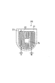
この現像剤残量検知手段の一方式として、フラットアンテナ方式がある。フラットアンテナ(平面アンテナ)は、図3に示すように、基板21に一対の導電パターン22、23を所定の間隔で形成したもので、これを、例えば、現像剤収納容器側面の現像剤と接する位置に配置し、現像剤収納容器内の現像剤が減少するのに従い、現像剤と平面アンテナ20との接触面積が減少するようしたものである。
【0008】
現像剤の消費によりこの導電パターン表面と現像剤との接触面積が変化することで静電容量が変化し、これにより、容器内現像剤残量と平面アンテナの静電容量との対応付づけが可能になり、平面アンテナの静電容量を測定することにより随時容器内現像剤残量を知ることができる。
【0009】
平面アンテナ20の静電容量は、一対の導電部22、23の一方に一定の交流バイアスを印加し、その際にもう一方の導電部に流れる電流から知ることができる。
【0010】
上述の方法などを用いた現像剤量検出装置を備えることで、現像剤残量検知が可能となり、ユーザーに対してカートリッジ内の現像剤量を報知することができる。
【0011】
【発明が解決しようとする課題】
しかしながら、正確にユーザーに対して現像剤量を報知するためには、上述のような現像剤残量検知手段などが故障する可能性も考慮することが望まれる。
【0012】
従って本発明の主たる目的は、上記従来技術を更に発展させ、カートリッジ及び画像形成装置の異常検知を可能とし、異常が発生したカートリッジ及び画像形成装置が使用されることで更に甚大な破損に到ることを未然に防ぐことのできる異常検知システムを提供することである。
【0014】
【課題を解決するための手段】
上記目的は本発明に係る異常検知システムにて達成される。要約すれば、本発明は、現像剤収納容器と、前記現像剤収納容器内の現像剤残量を逐次検知できる現像剤残量検知手段と、現像剤残量に係わる情報を記憶する記憶手段と、を有するカートリッジが着脱自在な画像形成装置における、該画像形成装置及び/又は該カートリッジの異常検知システムであって、前記現像剤残量検知手段からの検知出力を第1の統計的手法により処理して現像剤残量を確定する処理手段と、前記処理手段によって確定された現像剤残量を前記記憶手段に書き込む手段と、前記処理手段によって確定された現像剤残量と前記記憶手段に記憶されている現像剤残量とを比較する比較手段と、前記比較手段によって、前記第1の統計的手法とは異なる第2の統計的手法により処理して確定された現像剤残量と前記記憶手段に記憶されている現像剤残量とを比較した結果に基づいて、前記画像形成装置及び/又は前記カートリッジの異常を判断する判断手段と、を有し、前記判断手段は、前記比較手段の比較の結果、前記第2の統計的手法により確定した現像剤残量と前記記憶手段に記憶されている現像剤残量との差の値が所定量より大きい場合は前記画像形成装置及び/又は前記カートリッジの異常と判断し、前記画像形成装置が備える情報表示部及び/又は前記画像形成装置と通信可能なディスプレイを有する機器に異常を判断したことを示す情報を出力し、前記比較手段の前記比較の結果、前記第2の統計的手法により確定した現像剤残量と前記記憶手段に記憶されている現像剤残量との差の値が前記所定値より小さい場合は、その後、前記第1の統計的手法により確定した現像剤残量と前記記憶手段に記憶されている現像剤残量とを比較した結果に応じて異常を判断し、前記画像形成装置が備える情報表示部及び/又は前記画像形成装置と通信可能なディスプレイを有する機器に異常を判断したことを示す情報を出力することを特徴とする前記異常検知システムである。
【0019】
【発明の実施の形態】
以下、本発明に係る異常検知システムを図面に則して更に詳しく説明する。
【0020】
実施例1
先ず、図1〜図4を参照して、本発明に従って構成されるプロセスカートリッジを装着可能な電子写真画像形成装置の一実施例について説明する。本実施例にて、電子写真画像形成装置は、電子写真式のレーザービームプリンタAとされる。
【0021】
図4に示すように、レーザープリンタAは、パーソナルコンピュータ或はワークステーション等のホスト41に接続されて使用されるものであり、その構成は、電子写真画像形成プロセスによって記録材、例えば、記録紙、OHPシート、布などに画像形成を行うエンジン部Cと、ホスト41と直接接続され、ホスト41からのプリント要求信号とともに受け取ったページ記述言語を画像データへと展開する展開手段であるコントローラ部Dとに大別される。
【0022】
エンジン部Cの動作全般は、エンジン部Cに搭載されたE−コントローラ42によって制御される。ビデオインターフェース(I/F)43を介して、エンジン部Cとコントローラ部Dとは相互に通信可能である。
【0023】
先ず、エンジン部Cにおいて実行される電子写真画像形成プロセスについて説明する。図1に示すように、レーザビームプリンタAのエンジン部Cは、ドラム形状の電子写真感光体、即ち、感光体ドラム1を備える。感光体ドラム1は、帯電手段である帯電ローラ2によって帯電され、次いで、レーザースキャナー3により、コントローラ部Dにおいて展開された画像データに応じた潜像が形成される。この潜像は、現像手段5によって現像され、可視像、即ち、トナー像とされる。
【0024】
つまり現像手段5は、現像剤担持体としての現像ローラ5aを備えた現像室5Aを有しており、現像室5Aに隣接して形成された現像剤収納部としての現像剤収納容器4内の現像剤Tを現像剤送り部材10の回転によって、現像室5Aの現像ローラ5aへと送り出す。本実施例では、現像剤Tとしては、絶縁性1成分トナーを用いた。又、現像ローラ5aは、固定磁石5bを内蔵しており、現像ローラ5aを回転することによって、現像剤は搬送され、現像ブレード5cにて摩擦帯電電荷が付与されると共に所定厚の現像剤層とされ、感光体ドラム1の現像領域へと供給される。この現像領域へと供給された現像剤は、感光体ドラム1上の潜像へと転移され、トナー像を形成する。現像ローラ5aは、現像バイアス回路に接続されており、通常、交流電圧に直流電圧が重畳された現像バイアス電圧が印加される。
【0025】
一方、トナー像の形成と同期して給紙カセット200にセットした記録材Pをピックアップローラ8、搬送手段9Aを介して転写位置へと搬送する。転写位置には、転写手段としての転写ローラ6が配置されており、電圧を印加することによって、感光体ドラム1上のトナー像を記録材Pに転写する。
【0026】
トナー像の転写を受けた記録材Pは、搬送手段9Bで定着手段10へと搬送される。定着手段10は、ヒータ10aを内蔵した定着ローラ10b及び駆動ローラ10cを備え、通過する記録材Pに熱及び圧力を印加して転写されたトナー像を記録材P上に定着する。
【0027】
記録材Pは、搬送手段9Cにより排出トレイ14へと排出される。この排出トレイ14はレーザービームプリンタAの装置本体の上面に設けられている。
【0028】
転写ローラ6によってトナー像を記録材Pに転写した後の感光体ドラム1は、クリーニング手段7によって感光体ドラム1上に残留した現像剤を除去した後、次の画像形成プロセスに供される。クリーニング手段7は、感光体ドラム1に当接して設けられた弾性クリーニングブレード7aによって感光体ドラム7上の残留現像剤を掻き落として現像剤溜め7bへと集める。
【0029】
本実施例においては、図2に示すように、プロセスカートリッジBが、電子写真画像形成装置本体100に対して着脱可能である。即ち、現像剤を収納する現像剤収納容器(現像剤収納部)4及び現像剤送り部材10を有する現像剤枠体11と、現像ローラ5a及び現像ブレード5cなどの現像手段5を保持する現像枠体12とを溶着して一体として現像ユニットを形成し、更にこの現像ユニットに、感光体ドラム1、クリーニングブレード7aなどのクリーニング手段7及び帯電ローラ2を取り付けたクリーニング枠体13を一体に結合することによって、カートリッジ化されている。
【0030】
このプロセスカートリッジBは、ユーザーによって画像形成装置本体100に設けたカートリッジ装着手段101(図1)に対して取り外し可能に装着される。
【0031】
本発明によれば、プロセスカートリッジBは、現像剤収納容器4内の現像剤Tの消費に従ってその残量を逐次検知することのできる、現像剤残量検知手段20を有している。次に、この現像剤残量検知手段について説明する。
【0032】
現像剤残量検知手段である平面アンテナ20は、現像剤収容容器4の内面側壁に配設されている。又、本実施例によれば、上述のように現像剤収納容器4内には、図1の矢印方向に回転する攪拌手段10が設けられており、この攪拌手段10が回転することでほぐされつつ現像ローラ5aに供給される。
【0033】
図3に示すように、平面アンテナ20は、一般に用いられているプリント基盤21上に、エッチングや印刷などで二つの導体パターン22、23を形成したものである。又、この回路図形を保護するために導体パターン22、23上に保護膜(図示せず)が形成してある。導体パターンは適当に設定すればよく、本実施例では、この平面アンテナ20の二つの導体パターン22、23の幅(W)を300μm、両導体パターン22、23の間隔(G)を300μm程度まで狭くしてある。
【0034】
本実施例の平面アンテナ20にて、各導電パターンの電極22、23間に交流バイアスとして200Vpp、2000Hzを印加すると、平面アンテナ20上に現像剤が触れていないときには20pF、平面アンテナ20上の全面に現像剤が触れているときには60pFと、異なる静電容量値が観測された。
【0035】
画像形成工程を繰り返すことで現像剤収納容器4内現像剤Tが減少するのに伴い、現像剤Tと平面アンテナ20との接触面積が減少し、それに応じて平面アンテナ20上の電極21、22間における静電容量も減少する。従って、この静電容量を観測することで、随時容器4内現像剤T量を知ることができる。
【0036】
ところが実際には、現像剤収納容器4内の現像剤Tが徐々に減っても、平面アンテナ20上にわずかながら付着して残る現像剤のために、測定結果にばらつきが生じてしまう。
【0037】
そこで、その表面に付着した現像剤を除去するため、撹拌手段10の端部にアンテナ清掃手段10a(図2)を設けて、攪拌手段10の回転に伴い平面アンテナ20表面を清掃している。このアンテナ清掃手段(表面清掃手段)10aは、例えばPET(ポリエチレンテレフタレート)のシートであり、平面アンテナ20の表面をなでるように清掃する。
【0038】
図3に示すように、平面アンテナ20のほぼ中央部に穴24を設け、撹拌手段10の支持軸がこの穴24を貫通して現像剤収納容器4などに回転自在に支持される構成とすることで、平面アンテナ20のほぼ全域を清掃することができる。
【0039】
上記構成により、平面アンテナ20上にわずかながら付着して残る現像剤による測定結果のばらつきはほぼ解消できるが、平面アンテナ20の出力が表面清掃手段10aの回転周期で変動してしまう。
【0040】
そこで、本実施例では、表面清掃手段10aの回転周期に応じてアンテナ出力の平均値をとったり、最小値を選んだりするなどの統計的処理がなされる。
【0041】
しかしながら、現像剤残量レベルを確定させるためには、平面アンテナ20へバイアスを印加し、更には攪拌手段10及び表面清掃手段10a(攪拌手段10)の回転などを行い、表面清掃手段10aの回転周期に応じたアンテナ出力の統計処理を実行する必要があるため、その分の時間が必要となる。
【0042】
更に説明すると、プロセスカートリッジBに配設された現像剤残量検知手段20からの出力信号は、エンジン部Cに配設された信号処理手段44により統計処理がなされる。更に、予め対応付けられた平面アンテナ20を用いて検知される静電容量と現像剤量の関係を用いて、現像剤収納容器4内の現像剤残量レベルとして確定される。
【0043】
本実施例では、現像剤残量レベルは、未使用の状態における現像剤残量を100%とし、現像剤が画像形成に全て消費された状態における現像剤残量を0%としたパーセントで示される。
【0044】
又、本発明によればプロセスカートリッジBに記憶手段31を配設し、この記憶手段31に、確定した現像剤残量レベルを随時書き込み、記憶させる。
【0045】
このように、プロセスカートリッジBに記憶手段31を配設することで、カートリッジBを交換使用した場合においても、各々のカートリッジにおける現像剤残量レベルを保存することができる。
【0046】
本実施例では、プロセスカートリッジBに搭載する記憶手段31は、シリアルデータ入出力型の不揮発性メモリであり、その記憶容量は16bitである。この容量で十分、0〜100までの整数を表すことができる。よって、現像剤収納容器4内の現像剤残量レベルをパーセントで記憶させることが可能である。
【0047】
本実施例において用いた不揮発性メモリの他、記憶手段31としては電源を備えた揮発性メモリ等も使用可能であり、更には画像形成装置本体100と記憶手段31とを機械的に接続することなく通信することが可能な非接触メモリを使用することも可能である。
【0048】
又、記憶手段31に対するデータの書き込み、読み出し手段32は、エンジン部Cに配設されている。
【0049】
記憶手段31へのデータの書き込み及び読みこみの際には、使用するデバイスの特性により、適当な待ち時間が設定されており、その動作は保証されている。
【0050】
次に、本実施例における現像剤残量検知システム、並びにカートリッジ及び画像形成装置の異常検知システムについて説明する。
【0051】
先ず、現像剤の残量検知方法について説明する。本実施例では、画像形成装置本体100が稼動している間は、常時現像剤残量レベルを装置本体100の表示部であるディスプレイ33(図4)或はパーソナルコンピュータやワークステーションなどとされるホスト41に設けられた情報表示部であるディスプレイ41a(図4)に表示することが可能であり、且つ異常が発生した場合にはその旨を瞬時に装置本体100のディスプレイ33或はホスト41のディスプレイ41aに表示することが可能とされる。勿論、装置本体100のディスプレイ33及びホスト41のディスプレイ41aの両方に表示させることも可能である。
【0052】
現像剤残量レベル及び異常が発生した旨を、画像形成装置本体の表示部33或は画像形成装置と通信可能なディスプレイを有する機器に対して信号を出力するための信号出力手段47は、コントローラ部Dに配設される。これにより、現像剤残量レベル及び異常が発生した旨を画像形成装置と通信可能なディスプレイを有する機器であるパーソナルコンピュータやワークステーション等のホスト41に表示することが容易となる。
【0053】
上述のように、現像剤収納容器4内の現像剤残量は、平面アンテナからの出力を統計的処理することで確定される。この処理はエンジン部CのE−コントローラ42に配設された信号処理手段44において実行される。
【0054】
画像形成装置本体100の電源スイッチを入れた直後や、カートリッジ交換直後、ジャム処理直後から、平面アンテナ20へ交流バイアスが印加され、現像剤残量検知手段20により現像剤残量レベル検知が行われる。
【0055】
前述したように、画像形成装置本体100の電源スイッチを入れた直後や、カートリッジ交換直後、ジャム処理直後においては、平面アンテナ20へバイアスを印加し、更には攪拌手段10及び表面清掃手段10aの回転などを行い、表面清掃手段10aの回転周期に応じたアンテナ出力の統計処理を実行して現像剤残量レベルを確定させるための十分な時間が無く、現像剤残量レベルを表示することができない。従って、このような時間帯では、使用者は現像剤残量レベルを知ることができない。
【0056】
そこで、前回の現像剤残量検知により確定され、プロセスカートリッジBに配設された記憶手段31に記憶保存された現像剤残量レベルを、エンジン部Cに配設された書き込み、読み出し手段32が読み出し、ビデオインターフェース(I/F)43を介してコントローラ部Dに配設された信号出力手段47と通信し、装置本体100のディスプレイ33及び/又はパーソナルコンピュータやワークステーション等のホスト41のディスプレイ41aに表示する。
【0057】
これにより、画像形成装置本体100の電源スイッチを入れた直後や、カートリッジ交換直後、ジャム処理直後などの、現像剤残量レベルを確定するまでに十分な時間が経過していない期間であっても、直ちに使用者に現像剤残量を知らせることができる。このとき、カートリッジ及び画像形成装置の異常検知が行われる。
【0058】
続いて、カートリッジ及び画像形成装置の異常検知方法について説明する。現像剤残量レベルを検知できる平面アンテナ20のような現像剤残量検知手段20は故障する可能性がある。故障の原因としては、接点不良、バイアス印加不良等の電気的なものや、平面アンテナ20の破損等の機械的なものが考えられるが、いずれの場合においても画像形成装置及びカートリッジの双方に甚大な影響を及ぼす可能性が高い。よって、遅くとも画像形成を行うより前に、異常検知が実行されなければならない。
【0059】
前述したように、ある程度の画像形成を行うなど、攪拌手段10の回転を行い、攪拌手段10の回転周期に応じたアンテナ出力の統計処理を実行しなければならず、この時点において現像剤残量レベルを正確に確定することはできない。従って、通常の統計的処理によって確定された現像剤残量に基づいて上述のような異常を検知するためには、斯かる処理が終了するまで待たなければならず、遅くとも画像形成開始以前に迅速に異常を検知するということができない。
【0060】
一方、通常の統計的処理とは異なる精度の粗い統計的処理ならば、短時間でおおよその現像剤残量レベルは検知可能である。そこで、本実施例では、先ず、通常の統計的処理とは異なるこの精度の粗い(簡略な)統計的処理により求められるおおよその現像剤残量を用いて、迅速にカートリッジ及び画像形成装置の異常を検知する構成とする。
【0061】
この簡略な統計処理は、エンジン部Cに配設された信号処理手段44によりなされる。予め対応付けられた、平面アンテナ20を用いて検知される静電容量と現像剤量の関係から、現像剤収容容器4内のおおよその現像剤残量レベルとして確定される。
【0062】
つまり、上述のように、現像剤収納容器4内の現像剤量は、通常、攪拌手段10の回転を例えば10回転行う間に検出される平面アンテナ20の出力の平均値をとる、といった統計的処理をして確定している。これに対して、上述の簡略な統計的処理としては、
(1)攪拌手段10の回転を行わないで、平面アンテナ20にバイアスを印加することが考えられる。この場合、平面アンテナ20に現像剤が付着して残っている可能性が高いが、大まかな検知においては問題ない。他には、
(2)攪拌手段10の回転が1回転行われる間に検出されるアンテナ出力の平均値をとることもできる。検知精度は低下するが大まかな検知においては問題ない。
【0063】
確定されたおおよその現像剤残量レベルは、信号処理手段44から、ビデオインターフェース(I/F)43を介してコントローラ部Dに配設された比較手段46に送信される。
【0064】
同時に、前回の現像剤残量検知により確定され、プロセスカートリッジBに配設された記憶手段31に記憶保存された現像剤残量レベルを、エンジン部Cに配設された書き込み、読み出し手段32が読み出し、ビデオインターフェース(I/F)43を介してコントローラ部Dに配設された比較手段46に送信する。
【0065】
比較手段46において、おおよその現像剤残量レベルと、前回の画像形成時等において確定されプロセスカートリッジの記憶手段31に記憶された現像剤残量レベルとの間に所定の閾値Xを超えた大きな差異が認められた時は、現像剤残量検知手段20の破損、表面清掃手段10aの破損、電気的な短絡、画像形成装置本体100の故障等の発生が考えられる。
【0066】
この場合、プロセスカートリッジB又は画像形成装置本体100の異常や故障が発生したと判断し、コントローラ部Dに配設された比較手段46は、同じくコントローラ部Dに配設された信号出力手段47と通信し、異常が発生した旨を装置本体100のディスプレイ33及び/又はパーソナルコンピュータやワークステーション等のホスト41のディスプレイ41aに表示し、使用者にその旨を報知する。
【0067】
表示内容は、現像剤残量検知手段20の故障発生、装置本体100の故障発生等、故障発生の可能性又は故障の原因を示すもの、或はプロセスカートリッジBや装置本体100の点検が必要であること等、メンテナンスの必要性を示唆するものであってもよい。
【0068】
この時、コントローラ部Dに配設された比較手段46は、ビデオインターフェース(I/F)43を介してエンジン部Cに配設された書き込み、読み出し手段32と通信し、プロセスカートリッジBに搭載している記憶手段31に異常が発生した旨の情報を記憶させる。これにより、プロセスカートリッジBを装置本体100に対して交換装着した場合にも、故障した可能性があるプロセスカートリッジであることが瞬時に判別でき、異常が発生したカートリッジの使用を避けられるようにしている。
【0069】
又、比較手段46において、上記所定の閾値Xよりも両者の差が小さいと認められた場合には、問題なきものと判断し、異常検知は終了する。
【0070】
上記の簡略な統計的処理によって得られた現像剤残量を用いた異常検知の後、通常の統計的処理による現像剤残量の確定が行われる。即ち、画像形成動作中に行われる現像剤残量検知においては、より正確な現像剤残量レベルを使用者に報知し、更に、常時カートリッジ及び画像形成装置の異常検知を可能とするするために、現像剤残量検知手段20の出力信号に対して通常の統計的処理を行うことで現像剤残量レベルを確定し、確定された現像剤残量レベルとプロセスカートリッジBの記憶手段31に記憶させた現像剤残量レベルとを、コントローラ部Dに配設された比較手段46及びエンジン部Cに配設された比較手段45によって以下に示すように2段階で比較する。
【0071】
先ず、1段階目では、コントローラ部Dに配設された比較手段46において両者の差の絶対値の大きさが比較される。
【0072】
本実施例の現像剤残量検出装置30のように逐次残量を検知する装置では、n回目の検知により確定された現像剤残量レベルとn+1回目の検知により確定された現像剤残量レベルの間であまりにも大きな差が出るはずがない。よって所定の閾値Xを超えた大きな差異が認められる時は現像剤残量検知手段20の破損、表面清掃手段10aの破損、電気的な短絡、画像形成装置本体の故障等に起因することが考えられる。
【0073】
この場合も、前述したのと同様に、プロセスカートリッジB又は画像形成装置本体100の異常や故障が発生したと判断し、コントローラ部Dに配設された比較手段46は、同じくコントローラ部Dに配設された信号出力手段47と通信し、異常が発生した旨を装置本体100のディスプレイ33及び/又はパーソナルコンピュータやワークステーション等のホスト41のディスプレイ41aに表示し、使用者にその旨を報知し、且つ、プロセスカートリッジBに搭載している記憶手段31に、異常が発生した旨の情報を記憶させる。
【0074】
次に、2段階目では、エンジン部Cに配設された比較手段45において、確定された現像剤残量レベルとプロセスカートリッジBの記憶手段31に記憶された現像剤残量レベルの大小関係を比較する。
【0075】
原理的に、現在確定された現像剤残量レベルが、前回の画像形成時等において確定されプロセスカートリッジBの記憶手段31に記憶された現像剤残量レベルよりも大きい値であることはあり得ない。よって、確定された現像剤残量レベルがプロセスカートリッジBの記憶手段31に記憶させた現像剤残量レベルよりも大きい場合は測定誤差とみなすことができる。
【0076】
このような場合、使用者に現像剤残量レベルが増加したような誤情報を与えないためにも、装置本体100のディスプレイ33及び/又はパーソナルコンピュータやワークステーション等のホスト41のディスプレイ41aには、前回の現像剤残量検知において確定された現像剤残量レベルを表示する。
【0077】
つまり、コントローラ部Dに配設された信号出力手段47に対して、前回の現像剤残量検知において確定された現像剤残量レベルを現在確定された現像剤残量レベルで更新する入力を行わない。よって、エンジン部Cに配設された書き込み、読み出し手段32に対しても、現像剤残量レベルの書き込み要求はしない。
【0078】
現在確定された現像剤残量レベルがプロセスカートリッジの記憶手段31に記憶させた現像剤残量レベルよりも小さい場合には、エンジン部Cに配設された比較手段45は、ビデオインターフェース(I/F)43を介してコントローラ部Dに配設された信号出力手段47と通信し、現在確定された現像剤残量レベルを新たな現像剤残量レベルとして、装置本体100のディスプレイ及び/又はパーソナルコンピュータやワークステーション等のホスト41のディスプレイ41aに表示し、使用者に報知する。
【0079】
同時に、エンジン部Cに配設された書き込み、読み出し手段32に対しては、現在確定された現像剤残量レベルを新たな現像剤残量レベルとして記憶手段31に書き込むように要求する。
【0080】
プロセスカートリッジBに記憶手段31を配設することで、現像剤残量を各々のカートリッジに保存することができる。よって、カートリッジBを交換使用した場合にも、交換したカートリッジが有する記憶手段31から現像剤残量レベル情報を呼び出すことで、ユーザーは各カートリッジに即した現像剤残量レベルを直ちに知ることができる。又、同時にそのカートリッジ及び画像形成装置の異常検知が可能となる。
【0081】
尚、カートリッジBが新品である場合は、記憶手段31には予め工場出荷段階で収納されている現像剤残量が記憶されているので、現像剤残量レベルが確定するまではこのレベルを読み出し、表示する。
【0082】
このように、本実施例によれば、エンジン部Cからコントローラ部Dに対しては、現像剤残量検知手段20が検知して現在確定された現像剤残量レベルと、記憶手段31に記憶された前回の現像剤残量検知において確定された現像剤残量レベルとの2系統の現像剤残量レベルに関する出力がなされる。
【0083】
次に、図5に示すフローチャートを参照して本実施例による現像剤残量検知方法並びにカートリッジ及び画像形成装置の異常検知方法について説明する。図5は上記で説明した処理をフローチャートとして示す。
【0084】
本実施例では、画像形成装置本体100が稼動している間は、常時現像剤残量レベルを装置本体100のディスプレイ33及び/又はホスト41としてのパーソナルコンピュータのディスプレイ41aに表示しているものとする。
【0085】
本体電源スイッチを入れた直後、カートリッジ交換直後、ジャム処理直後などの現像剤残量検知手段20による現像剤残量レベルが未確定の場合(ステップ101)、エンジン部Cに配設されたデータ書き込み、読み出し手段32は、前回の現像剤残量検知で確定した現像剤残量レベルTA0をプロセスカートリッジBに搭載している記憶手段31から読み出し(ステップ102)、ビデオインターフェース(I/F)43を介してコントローラ部Dに配設された信号出力手段47に送信する。
【0086】
これを受けて、信号出力手段47は画像形成装置本体に設けられた表示部33或はパーソナルコンピュータ41に対してTA0をその時の現像剤残量レベルとして表示するよう信号を出力する(ステップ103)。
【0087】
尚、カートリッジBが新品である場合も記憶手段31には予め工場出荷段階で収納されている現像剤残量が記憶されているので、現像剤残量レベルが確定するまではこのレベルを読み出し、表示する。
【0088】
同時に、現像剤残量検知手段20による簡略な現像剤残量検知が実行される(ステップ104)。現像剤残量検知手段20からの出力信号は、エンジン部Cに配設された信号処理手段44において、通常の統計的処理とは異なる簡略な統計的処理が行われ、短時間でおおよその現像剤残量レベルTA1が確定される(ステップ105)。
【0089】
確定されたおおよその現像剤残量レベルTA1は、信号処理手段44からビデオインターフェース(I/F)43を介してコントローラ部Dに配設された比較手段46に送信される。
【0090】
更に、エンジン部Cに配設されたデータ書き込み、読み出し手段32により、前回の残量検知で確定した現像剤残量レベルTA0が、プロセスカートリッジBに搭載している記憶手段31から読み出され(ステップ106)、ビデオインターフェース(I/F)43を介してコントローラ部Dに配設された比較手段46に送信される。
【0091】
尚、カートリッジBが新品である場合も記憶手段31には予め工場出荷段階で収納されている現像剤残量が記憶されているので、このレベルを読み出す。
【0092】
コントローラ部Dに配設された比較手段46において、おおよその現像剤残量レベルTA1と記憶手段31から読み出された現像剤残量レベルTA0とが比較される(ステップ107)。
【0093】
前述したように、この両値の差が所定のXよりも大きい場合、何らかの異常が発生したと判断し、比較手段46は、同じくコントローラ部Dに配設された信号出力手段47と通信し、装置本体100のディスプレイ33及び/又はホスト41のディスプレイ41aに異常が発生した旨を示す信号を発信する(ステップ108)。
【0094】
同時に、比較手段46は、エンジン部Cに配設されたデータ書き込み、読み出し手段32と通信し異常が発生した旨の情報を記憶手段31に記憶させる(ステップ109)。
【0095】
ステップ107にて両値の差が所定のXよりも小さい場合は、異常なきものと判断する。
【0096】
ステップ104〜ステップ107による異常検知が終了して、現像剤残量検知手段20による検知が実行される(ステップ110)。
【0097】
又、プロセスカートリッジBが装置本体100に装着されており、且つ装置本体100の電源スイッチが入ったまましばらくの間プリントを行っていない状態からプリントを開始する場合(ステップ111)、現像剤の攪拌(アンテナの清掃)が始まって現像剤残量レベルが確定するまでにやはり時間を要するが、ディスプレイには既に前回の現像剤残量レベルが表示されているので、ステップ101〜103の工程は行わない。しかし、遅くとも画像形成動作以前にカートリッジ及び画像形成装置の異常を検知ように、ステップ104〜ステップ107の異常検知は実行される。
【0098】
その後、ある程度の画像形成を行うなど、現像剤残量検知手段20による現像剤検知が実行され(ステップ110)、エンジン部Cに配設された信号処理手段44により現在の現像剤残量レベルがTA2と確定される(ステップ112)。
【0099】
信号処理手段44は、確定された現像剤残量レベル値TA2を、エンジン部Cに配設された比較手段45、及びビデオインターフェース(I/F)43を介してコントローラ部Dに配設された比較手段46に出力する。同時に、プロセスカートリッジBに搭載している記憶手段31が記憶している現像剤残量レベルTA0がデータ書き込み、読み出し手段32により読みだされ(ステップ113)、エンジン部Cの比較手段45及びビデオインターフェース(I/F)43を介してコントローラ部Dの比較手段46に出力される。
【0100】
TA2とTA0は比較手段45及び比較手段46において以下の処理がなされる。
【0101】
先ず、コントローラ部Dに配設された比較手段46では、異常検知が行われる(ステップ114)。前述したように、現像剤残量検知手段20により検知され確定された現像剤残量レベルは、随時プロセスカートリッジBに搭載された記憶手段31に記憶される。よって、何らかの異常が無い限り、このTA2とTA0は非常に近い値のはずである。従って、この両値の差が所定のXよりも大きい場合には、何らかの異常が発生したと判断した比較手段46からの出力を受けて、コントローラ部Dに配設された信号出力手段47は異常が発生した旨を報知する信号を画像形成装置本体100に設けられた表示部33及び/又はホスト41に対して出力する(ステップ108)。
【0102】
又、比較手段46からの出力をビデオインターフェース(I/F)43を介してエンジン部Cに配設されたデータ書き込み、読み出し手段32が受け、プロセスカートリッジBの記憶手段31に前回の現像剤残量検知にて確定された現像剤残量レベルTA0の代わりに、現在確定された現像剤残量レベルTA2を上書きすること禁じ、且つ、異常が発生した旨の情報を記憶手段31に記憶させる(ステップ109)。
【0103】
一方、エンジン部Cに配設された比較手段45では、より正確な現像剤残量検知を可能とする処理が行われる。即ち、TA2とTA0のどちらが大きいかを比較し(ステップ115)、新しく確定した現像剤残量レベルTA2の方が大きい場合、比較手段45からの信号を受けて現像剤残量レベルに関して何ら更新要求を出さない。よって、コントローラ部Dに配設された信号出力手段47が表示部33及び/又はホスト41に対し送信する現像剤残量は、前回に確定された現像剤残量レベルTA0のままである(ステップ116)。
【0104】
又、現像剤残量検知手段20にり現在確定された現像剤残量レベルTA2の方がTA0より小さい場合、比較手段45からの信号を受けて現像剤残量レベルTA2がビデオインターフェース(I/F)43を介してコントローラ部Dに配設された信号出力手段47に送信される(ステップ117)。
【0105】
更に、比較手段45からの信号をデータ書き込み、読み出し手段32が受けて、記憶手段31のTA0をそのTA2の値に書き換え、新たなTA0として記憶する(ステップ118)。
【0106】
以上の工程を繰り返すことにより、現像剤残量表示が更新され、同時にカートリッジ及び画像形成装置の異常検知が実行される。
【0107】
尚、本実施例においては、現像剤残量レベルの比較機能の一部をコントローラ部に持たせる構成としたが、その全機能をコントローラ部が備える構成も可能である。その場合においても、コントローラ部Dとエンジン部Cの通信手段であるビデオインターフェース(I/F)43上で、現像剤残量検知手段により確定された現在の現像剤残量レベル値と、前回の残量検知で確定され記憶手段31に記憶された現像剤残量レベル値の2系統の現像剤残量レベルに関する出力を有することとなる。
【0108】
又、本実施例は、現像剤残量検知手段20として平面アンテナ方式を用いたが、本発明は、この方式の現像剤残量検知手段に限定するものではない。現像剤収納容器4内の攪拌トルク検知方式など現像剤残量レベルを逐次検知できれば、その方式は問わない。
【0109】
更に、画像形成装置本体100に配設されている信号処理手段44を、記憶手段31とともに、プロセスカートリッジBに搭載してもよい。両者に関わる演算処理装置をプロセスカートリッジBに搭載することにより、画像形成装置本体100とプロセスカートリッジBとの間で行われていたデータの書き込み、読み出し等の通信を簡略化することができる。その結果、接点不良及びノイズ等による通信エラーの発生機会を減少させることができ、安定した現像剤残量レベル検知を行うことができる。
【0110】
実施例2
図6には、本発明の他の態様であるカートリッジ化された現像装置Eの一実施例を示す。
【0111】
本実施例の現像装置Eは、現像ローラ5a及び現像ブレード5cなどの現像手段5を保持する現像室5Aと、現像剤手段5に現像剤を供給する現像剤を収容する現像剤収納容器4とをプラスチック製の現像剤枠体11及び現像枠体12により一体的に構成することによりカートリッジ化される。即ち、本実施例の現像装置Cは、実施例1で説明したプロセスカートリッジBの現像装置構成部をユニット化したものであり、即ち、プロセスカートリッジBから、感光体ドラム1、帯電手段2、クリーニング手段7を除いて一体化したカートリッジと考えることができる。従って、実施例1にて説明した全ての現像装置構成部及び現像剤量検出手段構成が同様に本実施例の現像装置においても適用される。従って、これら構成及び作用についての説明は、実施例1において行った上記説明を援用する。
【0112】
本実施例においても、実施例1と同様の作用効果を達成し得る。
【0113】
【発明の効果】
以上説明したように、本発明によれば、画像形成装置及び/又は画像形成装置に着脱可能なカートリッジの異常検知を可能とし、異常が発生した画像形成装置及び/又はカートリッジが使用されることで更に甚大な破損に到ることを未然に防ぐことができる。
【図面の簡単な説明】
【図1】本発明に係るプロセスカートリッジと画像形成装置の一実施例の断面図である。
【図2】図1のプロセスカートリッジの拡大断面図である。
【図3】本発明に係るプロセスカートリッジに搭載することのできる現像剤残量検知手段の図である。
【図4】本発明に係るプロセスカートリッジと画像形成装置の概略関係図である。
【図5】本発明に従った現像剤量に関する情報の表示動作を説明するフローチャートである。
【図6】本発明に係るカートリッジ化された現像装置の一実施例の断面図である。
【符号の説明】
1 感光体ドラム
2 帯電手段
3 レーザースキャナー
4 現像剤収納容器
5 現像手段
7 クリーニング手段
10 攪拌手段
10a 表面清掃手段
20 現像剤残量検知手段(平面アンテナ)
31 記憶手段
30 現像剤量検出装置
32 データ書き込み、読み出し手段
33 表示部
41 ホスト
42 E−コントローラ
43 ビデオインターフェース
44 信号処理手段
45 比較手段
46 比較手段
47 信号出力手段
100 画像形成装置本体
101 装着手段
A レーザービームプリンタ
B プロセスカートリッジ
C エンジン部
D コントローラ部
E 現像カートリッジ(現像装置)[0001]
BACKGROUND OF THE INVENTION
In general, the present invention relates to an image forming apparatus for forming an electrostatic latent image on an image carrier by an electrophotographic method, and developing the electrostatic latent image with a developer contained in a developing device, or the image forming apparatus. removable cartridge forming apparatus, that is, relates to the abnormality detection system such as a process cartridge and cartridge have been developing apparatus.
[0002]
Here, examples of the electrophotographic image forming apparatus include an electrophotographic copying machine, an electrophotographic printer (for example, an LED printer, a laser beam printer, etc.), an electrophotographic facsimile apparatus, and an electrophotographic word processor.
[0003]
The process cartridge is a cartridge in which at least one of a charging unit, a developing unit, and a cleaning unit and an electrophotographic photosensitive member are integrally formed, and the cartridge can be attached to and detached from the main body of the electrophotographic image forming apparatus. In other words, it means that at least the developing means and the electrophotographic photosensitive member are integrated into a cartridge, and the cartridge can be attached to and detached from the main body of the electrophotographic image forming apparatus.
[0004]
[Prior art]
Conventionally, in an image forming apparatus using an electrophotographic image forming process, the electrophotographic photosensitive member and the process means acting on the electrophotographic photosensitive member are integrally formed into a cartridge, and the cartridge can be attached to and detached from the main body of the electrophotographic image forming apparatus. The process cartridge method is adopted. According to this process cartridge system, the maintenance of the apparatus can be performed by the user himself / herself without depending on the service person, so that the operability can be remarkably improved. Therefore, this process cartridge system is widely used in electrophotographic image forming apparatuses.
[0005]
In such a process cartridge type electrophotographic image forming apparatus, when the developer runs out, the cartridge can be replaced to form an image again. However, the cartridge must be replaced by the user himself. A means for notifying the user when the developer is consumed, that is, a developer amount detecting device is required.
[0006]
The developer amount detecting device includes a developer amount detecting unit capable of detecting a developer remaining amount level in order to be able to know at any time how much developer that can be used for image formation in the cartridge remains. Alternatively, it can be provided in the image forming apparatus main body.
[0007]
There is a flat antenna method as one method of this developer remaining amount detecting means. As shown in FIG. 3, the flat antenna (planar antenna) is formed by forming a pair of
[0008]
The electrostatic capacity changes by changing the contact area between the surface of the conductive pattern and the developer due to the consumption of the developer, thereby associating the remaining amount of the developer in the container with the electrostatic capacity of the planar antenna. It becomes possible to know the remaining amount of developer in the container at any time by measuring the capacitance of the planar antenna.
[0009]
The electrostatic capacity of the
[0010]
By providing the developer amount detection device using the above-described method or the like, the remaining amount of developer can be detected, and the user can be notified of the amount of developer in the cartridge.
[0011]
[Problems to be solved by the invention]
However, in order to accurately notify the user of the developer amount, it is desirable to consider the possibility that the above-described developer remaining amount detecting means will break down.
[0012]
Accordingly, a main object of the present invention is to further develop the above-described conventional technology, enable abnormality detection of the cartridge and the image forming apparatus, and use of the cartridge and image forming apparatus in which the abnormality has occurred leads to further serious damage. It is an object of the present invention to provide an anomaly detection system that can prevent this in advance.
[0014]
[Means for Solving the Problems]
The above object is manually achieved abnormality detection system according to the present invention. In summary, the present invention relates to a developer storage container, a developer remaining amount detection means capable of sequentially detecting the remaining amount of developer in the developer storage container, and a storage means for storing information relating to the remaining amount of developer. , the cartridge is removable image forming apparatus having, I abnormality detection system der of the image forming apparatus and / or the cartridge, the detection output from said developer amount detecting means by the first statistical method Processing means for processing to determine the remaining amount of developer, means for writing the remaining developer amount determined by the processing means to the storage means, and the remaining developer amount determined by the processing means and the storage means Comparing means for comparing the stored developer remaining amount, and the developer remaining amount determined by processing by a second statistical method different from the first statistical method by the comparing means, Storage means Based on the result of comparison between the developer remaining amount stored, anda determining means for determining an abnormality of the image forming apparatus and / or the cartridge, the judgment unit may, of comparison of the comparing means As a result, when the difference between the developer remaining amount determined by the second statistical method and the developer remaining amount stored in the storage unit is larger than a predetermined amount, the image forming apparatus and / or the cartridge Information indicating that the abnormality is determined in an information display unit provided in the image forming apparatus and / or a device having a display communicable with the image forming apparatus. As a result, if the value of the difference between the developer remaining amount determined by the second statistical method and the developer remaining amount stored in the storage means is smaller than the predetermined value, then the first statistics Target Finalized the developer remaining amount in accordance with a result of comparison of the developer remaining amount stored in the storage means determines an abnormality, and the image forming apparatus information display unit and / or the image forming device provided in the Ru said abnormality detection system der, characterized in that outputs information indicating the determined abnormality in a device having a communicable display.
[0019]
DETAILED DESCRIPTION OF THE INVENTION
Hereinafter will be described in more detail with reference to the abnormality detection system according to the present invention with reference to the drawings.
[0020]
Example 1
First, an embodiment of an electrophotographic image forming apparatus to which a process cartridge constructed according to the present invention can be mounted will be described with reference to FIGS. In this embodiment, the electrophotographic image forming apparatus is an electrophotographic laser beam printer A.
[0021]
As shown in FIG. 4, the laser printer A is used by being connected to a
[0022]
The overall operation of the engine unit C is controlled by an
[0023]
First, an electrophotographic image forming process executed in the engine unit C will be described. As shown in FIG. 1, the engine unit C of the laser beam printer A includes a drum-shaped electrophotographic photosensitive member, that is, a photosensitive drum 1. The photosensitive drum 1 is charged by a charging roller 2 as charging means, and then a latent image corresponding to the image data developed in the controller unit D is formed by the laser scanner 3. This latent image is developed by the developing means 5 to be a visible image, that is, a toner image.
[0024]
That is, the developing means 5 has a developing
[0025]
On the other hand, in synchronization with the formation of the toner image, the recording material P set in the
[0026]
The recording material P that has received the transfer of the toner image is conveyed to the fixing
[0027]
The recording material P is discharged to the
[0028]
After the toner image is transferred to the recording material P by the
[0029]
In this embodiment, as shown in FIG. 2, the process cartridge B is detachable from the electrophotographic image forming apparatus
[0030]
The process cartridge B is detachably mounted on the cartridge mounting means 101 (FIG. 1) provided in the image forming apparatus
[0031]
According to the present invention, the process cartridge B has the developer remaining amount detecting means 20 that can sequentially detect the remaining amount according to the consumption of the developer T in the developer storage container 4. Next, the developer remaining amount detecting means will be described.
[0032]
The
[0033]
As shown in FIG. 3, the
[0034]
When 200 Vpp and 2000 Hz are applied as the AC bias between the
[0035]
As the developer T in the developer container 4 decreases by repeating the image forming process, the contact area between the developer T and the
[0036]
However, actually, even if the developer T in the developer container 4 is gradually reduced, the developer remains slightly adhered on the
[0037]
Therefore, in order to remove the developer adhering to the surface, an antenna cleaning means 10a (FIG. 2) is provided at the end of the stirring means 10, and the surface of the
[0038]
As shown in FIG. 3, a
[0039]
With the above configuration, the variation in the measurement result due to the developer that remains slightly adhered to the
[0040]
Therefore, in this embodiment, statistical processing is performed such as taking the average value of the antenna output or selecting the minimum value according to the rotation period of the surface cleaning means 10a.
[0041]
However, in order to determine the developer remaining amount level, a bias is applied to the
[0042]
More specifically, the output signal from the developer remaining amount detecting means 20 provided in the process cartridge B is subjected to statistical processing by the signal processing means 44 provided in the engine section C. Furthermore, the developer remaining amount level in the developer container 4 is determined using the relationship between the capacitance detected using the
[0043]
In this embodiment, the remaining developer level is expressed as a percentage where the remaining developer is 100% in an unused state, and the remaining developer is 0% when all the developer is consumed for image formation. It is.
[0044]
Further, according to the present invention, the storage means 31 is provided in the process cartridge B, and the determined remaining developer level is written and stored in the storage means 31 as needed.
[0045]
Thus, by providing the storage means 31 in the process cartridge B, even when the cartridge B is exchanged and used, the remaining amount of developer in each cartridge can be stored.
[0046]
In this embodiment, the storage means 31 mounted on the process cartridge B is a serial data input / output nonvolatile memory, and its storage capacity is 16 bits. This capacity is sufficient to represent an integer from 0 to 100. Therefore, the remaining developer level in the developer container 4 can be stored as a percentage.
[0047]
In addition to the non-volatile memory used in this embodiment, a volatile memory equipped with a power source can be used as the
[0048]
Further, the data writing / reading means 32 with respect to the storage means 31 is disposed in the engine unit C.
[0049]
When data is written to and read from the storage means 31, an appropriate waiting time is set according to the characteristics of the device used, and its operation is guaranteed.
[0050]
Next , the developer remaining amount detection system and the abnormality detection system for the cartridge and the image forming apparatus in the present embodiment will be described.
[0051]
First, a developer remaining amount detection method will be described. In this embodiment, while the image forming apparatus
[0052]
A signal output means 47 for outputting a signal to the
[0053]
As described above, the remaining amount of developer in the developer container 4 is determined by statistically processing the output from the planar antenna. This processing is executed by the signal processing means 44 provided in the E-controller 42 of the engine unit C.
[0054]
An AC bias is applied to the
[0055]
As described above, immediately after the power switch of the image forming apparatus
[0056]
Accordingly, the writing / reading means 32 provided in the engine unit C indicates the developer remaining level determined by the previous developer remaining amount detection and stored and stored in the storage means 31 provided in the process cartridge B. It communicates with the signal output means 47 provided in the controller unit D via the video interface (I / F) 43 for reading, and the
[0057]
As a result, even if a sufficient time has not elapsed until the developer remaining level is determined, such as immediately after the power switch of the image forming apparatus
[0058]
Next, an abnormality detection method for the cartridge and the image forming apparatus will be described. There is a possibility that the developer remaining amount detecting means 20 such as the
[0059]
As described above, the
[0060]
On the other hand, if the rough statistical process has a different accuracy from the normal statistical process, the approximate remaining developer level can be detected in a short time. Therefore, in this embodiment, first, an abnormality in the cartridge and the image forming apparatus is quickly performed by using the approximate developer remaining amount obtained by this rough (simple) statistical process different from the normal statistical process. It is set as the structure which detects.
[0061]
This simple statistical processing is performed by the signal processing means 44 disposed in the engine unit C. The approximate developer remaining level in the developer container 4 is determined from the relationship between the electrostatic capacity detected using the
[0062]
That is, as described above, the amount of developer in the developer storage container 4 is generally statistically determined to be an average value of the output of the
(1) It is conceivable to apply a bias to the
(2) It is also possible to take an average value of the antenna output detected while the stirring means 10 is rotated once. Although detection accuracy is lowered, there is no problem in rough detection.
[0063]
The determined approximate remaining developer level is transmitted from the
[0064]
At the same time, a writing /
[0065]
In the comparison means 46, a large value exceeding a predetermined threshold value X between the approximate developer remaining level and the developer remaining level determined in the previous image formation or the like and stored in the storage means 31 of the process cartridge. When the difference is recognized, it is considered that the developer remaining
[0066]
In this case, it is determined that an abnormality or failure has occurred in the process cartridge B or the image forming apparatus
[0067]
The displayed contents indicate the possibility of the occurrence of the failure such as the occurrence of the failure of the developer remaining
[0068]
At this time, the comparison means 46 provided in the controller part D communicates with the writing / reading means 32 provided in the engine part C via the video interface (I / F) 43 and is mounted on the process cartridge B. The storage means 31 stores information indicating that an abnormality has occurred. As a result, even when the process cartridge B is exchanged and attached to the apparatus
[0069]
If the comparison means 46 determines that the difference between the two is smaller than the predetermined threshold value X, it is determined that there is no problem, and the abnormality detection ends.
[0070]
After the abnormality detection using the developer remaining amount obtained by the above-described simple statistical processing, the developer remaining amount is determined by normal statistical processing. That is, in the developer remaining amount detection performed during the image forming operation, a more accurate developer remaining amount level is notified to the user, and furthermore, it is possible to always detect abnormality of the cartridge and the image forming apparatus. The developer remaining amount level is determined by performing normal statistical processing on the output signal of the developer remaining
[0071]
First, in the first stage, the magnitude of the absolute value of the difference between the two is compared by the comparison means 46 disposed in the controller unit D.
[0072]
In a device that sequentially detects the remaining amount, such as the remaining developer amount detecting device 30 of the present embodiment, the remaining developer level determined by the nth detection and the remaining developer level determined by the n + 1th detection. There should not be too much difference between them. Therefore, when a large difference exceeding the predetermined threshold value X is recognized, it may be caused by damage to the developer remaining
[0073]
In this case as well, as described above, it is determined that an abnormality or failure has occurred in the process cartridge B or the image forming apparatus
[0074]
Next, in the second stage, in the comparison means 45 arranged in the engine unit C, the magnitude relationship between the developer remaining level determined and the developer remaining level stored in the storage means 31 of the process cartridge B is shown. Compare.
[0075]
In principle, it is possible that the currently determined developer remaining level is larger than the developer remaining level determined in the previous image formation or the like and stored in the storage means 31 of the process cartridge B. Absent. Therefore, when the determined remaining developer level is higher than the remaining developer level stored in the storage means 31 of the process cartridge B, it can be regarded as a measurement error.
[0076]
In such a case, the
[0077]
That is, the signal output means 47 arranged in the controller unit D is input to update the developer remaining level determined in the previous developer remaining amount detection with the currently determined developer remaining level. Absent. Therefore, the writing / reading means 32 provided in the engine unit C is not requested to write the developer remaining level.
[0078]
When the currently determined developer remaining level is lower than the developer remaining level stored in the storage means 31 of the process cartridge, the comparing means 45 disposed in the engine unit C is connected to the video interface (I / I). F) It communicates with the signal output means 47 arranged in the controller unit D via 43, and the display of the apparatus
[0079]
At the same time, the writing /
[0080]
By disposing the
[0081]
If the cartridge B is new, the remaining amount of developer stored at the factory shipment stage is stored in advance in the storage means 31, so this level is read until the remaining developer level is determined. ,indicate.
[0082]
As described above, according to the present embodiment, the remaining developer level detected by the developer remaining
[0083]
Next, a developer remaining amount detection method and an abnormality detection method for the cartridge and the image forming apparatus according to this embodiment will be described with reference to a flowchart shown in FIG. FIG. 5 shows the process described above as a flowchart.
[0084]
In this embodiment, while the image forming apparatus
[0085]
When the developer remaining amount level by the developer remaining
[0086]
In response to this, the signal output means 47 outputs a signal to display TA0 as the remaining developer level at that time on the
[0087]
Even when the cartridge B is new, the remaining amount of developer stored in the
[0088]
At the same time, simple developer remaining amount detection by the developer remaining
[0089]
The determined approximate developer remaining level TA1 is transmitted from the
[0090]
Further, the developer remaining amount level TA0 determined by the previous remaining amount detection is read from the
[0091]
Even when the cartridge B is new, the remaining amount of developer stored in the
[0092]
In the comparison means 46 provided in the controller part D, the approximate developer remaining level TA1 is compared with the developer remaining level TA0 read from the storage means 31 (step 107).
[0093]
As described above, if the difference between the two values is larger than the predetermined X, it is determined that some abnormality has occurred, and the
[0094]
At the same time, the comparing
[0095]
If the difference between the two values is smaller than the predetermined X in
[0096]
The abnormality detection in steps 104 to 107 is completed, and the detection by the developer remaining amount detection means 20 is executed (step 110).
[0097]
When printing is started from a state in which the process cartridge B is mounted on the apparatus
[0098]
Thereafter, developer detection is performed by the developer remaining amount detecting means 20 such as performing image formation to some extent (step 110), and the current developer remaining level is set by the signal processing means 44 disposed in the engine section C. TA2 is determined (step 112).
[0099]
The
[0100]
TA2 and TA0 are processed in the comparison means 45 and the comparison means 46 as follows.
[0101]
First, abnormality detection is performed in the comparison means 46 provided in the controller part D (step 114). As described above, the developer remaining amount level detected and fixed by the developer remaining
[0102]
The output from the comparison means 46 is received by the data writing / reading means 32 disposed in the engine section C via the video interface (I / F) 43, and the previous developer remaining in the storage means 31 of the process cartridge B. Instead of overwriting the developer remaining amount level TA2 determined in the amount detection, it is prohibited to overwrite the developer remaining amount level TA2 that is currently determined, and information indicating that an abnormality has occurred is stored in the storage means 31 ( Step 109).
[0103]
On the other hand, the comparison means 45 disposed in the engine unit C performs processing that enables more accurate detection of the developer remaining amount. That is, a comparison is made as to which of TA2 and TA0 is greater (step 115). If the newly determined developer remaining amount level TA2 is greater, an update request regarding the remaining developer level is received in response to a signal from the comparison means 45. Do not give out. Therefore, the remaining amount of developer transmitted to the
[0104]
When the developer remaining amount level TA2 currently determined by the developer remaining
[0105]
Further, the signal from the comparison means 45 is written and read by the reading means 32, TA0 in the storage means 31 is rewritten to the value of TA2 and stored as a new TA0 (step 118).
[0106]
By repeating the above steps, the developer remaining amount display is updated, and at the same time, abnormality detection of the cartridge and the image forming apparatus is executed.
[0107]
In the present embodiment, the controller unit has a part of the developer remaining level comparison function. However, a configuration in which the controller unit has all the functions is also possible. Even in that case, on the video interface (I / F) 43 which is a communication means between the controller unit D and the engine unit C, the current developer remaining amount level value determined by the developer remaining amount detecting unit and the previous time This means that there are outputs relating to the remaining developer level of the two systems of the remaining developer level value determined by the remaining amount detection and stored in the storage means 31.
[0108]
In this embodiment, the planar antenna method is used as the developer remaining
[0109]
Further, the
[0110]
Example 2
FIG. 6 shows an embodiment of the developing device E in the form of a cartridge according to another aspect of the present invention.
[0111]
The developing device E of the present embodiment includes a developing
[0112]
Also in the present embodiment, the same effect as that of the first embodiment can be achieved.
[0113]
【The invention's effect】
As described above, according to the present invention, to enable the abnormality detection of the removable cartridge images forming apparatus and / or the image forming apparatus, abnormal images forming apparatus and / or the cartridge has occurred is used This can prevent further serious damage.
[Brief description of the drawings]
FIG. 1 is a cross-sectional view of an embodiment of a process cartridge and an image forming apparatus according to the present invention.
FIG. 2 is an enlarged cross-sectional view of the process cartridge of FIG.
FIG. 3 is a diagram of a developer remaining amount detecting means that can be mounted on a process cartridge according to the present invention.
FIG. 4 is a schematic relationship diagram of a process cartridge and an image forming apparatus according to the present invention.
FIG. 5 is a flowchart for explaining a display operation of information related to a developer amount according to the present invention.
FIG. 6 is a cross-sectional view of an embodiment of the developing device formed into a cartridge according to the present invention.
[Explanation of symbols]
DESCRIPTION OF SYMBOLS 1 Photosensitive drum 2 Charging means 3 Laser scanner 4 Developer storage container 5 Developing means 7 Cleaning means 10 Stirring means 10a Surface cleaning means 20 Developer remaining amount detection means (planar antenna)
31 storage means 30 developer
Claims (1)
前記現像剤残量検知手段からの検知出力を第1の統計的手法により処理して現像剤残量を確定する処理手段と、
前記処理手段によって確定された現像剤残量を前記記憶手段に書き込む手段と、
前記処理手段によって確定された現像剤残量と前記記憶手段に記憶されている現像剤残量とを比較する比較手段と、
前記比較手段によって、前記第1の統計的手法とは異なる第2の統計的手法により処理して確定された現像剤残量と前記記憶手段に記憶されている現像剤残量とを比較した結果に基づいて、前記画像形成装置及び/又は前記カートリッジの異常を判断する判断手段と、
を有し、
前記判断手段は、前記比較手段の比較の結果、前記第2の統計的手法により確定した現像剤残量と前記記憶手段に記憶されている現像剤残量との差の値が所定量より大きい場合は前記画像形成装置及び/又は前記カートリッジの異常と判断し、前記画像形成装置が備える情報表示部及び/又は前記画像形成装置と通信可能なディスプレイを有する機器に異常を判断したことを示す情報を出力し、前記比較手段の前記比較の結果、前記第2の統計的手法により確定した現像剤残量と前記記憶手段に記憶されている現像剤残量との差の値が前記所定値より小さい場合は、その後、前記第1の統計的手法により確定した現像剤残量と前記記憶手段に記憶されている現像剤残量とを比較した結果に応じて異常を判断し、前記画像形成装置が備える情報表示部及び/又は前記画像形成装置と通信可能なディスプレイを有する機器に異常を判断したことを示す情報を出力することを特徴とする前記異常検知システム。A cartridge having a developer storage container, a developer remaining amount detection means capable of sequentially detecting the developer remaining amount in the developer storage container, and a storage means for storing information relating to the developer remaining amount is detachable . in the image forming apparatus, I abnormality detection system der of the image forming apparatus and / or the cartridge,
Processing means for processing the detection output from the developer remaining amount detecting means by a first statistical method to determine the developer remaining amount;
Means for writing the remaining amount of developer determined by the processing means into the storage means;
Comparing means for comparing the developer remaining amount determined by the processing means and the developer remaining amount stored in the storage means ;
A result of comparing the remaining amount of developer determined by the second statistical method different from the first statistical method and the remaining amount of developer stored in the storage unit by the comparison unit A determination means for determining abnormality of the image forming apparatus and / or the cartridge based on
Have
The determination means has a value of a difference between the developer remaining amount determined by the second statistical method as a result of the comparison by the comparison means and the developer remaining amount stored in the storage means larger than a predetermined amount. Information indicating that the image forming apparatus and / or the cartridge is abnormal, and an information display unit included in the image forming apparatus and / or a device having a display communicable with the image forming apparatus is determined to be abnormal. The difference value between the developer remaining amount determined by the second statistical method and the developer remaining amount stored in the storage unit as a result of the comparison by the comparison unit is greater than the predetermined value. If it is smaller, then the abnormality is determined according to the result of comparing the remaining developer amount determined by the first statistical method with the remaining developer amount stored in the storage unit, and the image forming apparatus Information The abnormality detection system and outputs a radical 113 and / or information indicating that determines an abnormality in a device having a communicable display and the image forming apparatus.
Priority Applications (7)
| Application Number | Priority Date | Filing Date | Title |
|---|---|---|---|
| JP35672899A JP3912947B2 (en) | 1999-12-15 | 1999-12-15 | Anomaly detection system |
| US09/650,752 US6912366B1 (en) | 1999-08-31 | 2000-08-29 | Image forming apparatus comprising means for detecting an amount of developer contained in a developer container, a memory for storing the amount detected by the detecting means, and control means for updating the information stored in the memory |
| DE60032297T DE60032297T2 (en) | 1999-08-31 | 2000-08-30 | Image forming apparatus and detachable attached unit |
| EP04030258A EP1522903A3 (en) | 1999-08-31 | 2000-08-30 | Image forming apparatus and cartridge detachably attachable thereto |
| EP00118744A EP1081559B1 (en) | 1999-08-31 | 2000-08-30 | Image forming apparatus and cartridge detachably attachable thereto |
| US10/265,337 US6925267B2 (en) | 1999-08-31 | 2002-10-07 | Memory device storing information warning a user about the developer-remaining amount, a process cartridge including a memory storing such information, and a control system and a memory system for warning a user about the developer-remaining amount |
| US10/386,687 US7068955B2 (en) | 1999-08-31 | 2003-03-13 | Image forming apparatus having developer amount detector |
Applications Claiming Priority (1)
| Application Number | Priority Date | Filing Date | Title |
|---|---|---|---|
| JP35672899A JP3912947B2 (en) | 1999-12-15 | 1999-12-15 | Anomaly detection system |
Publications (3)
| Publication Number | Publication Date |
|---|---|
| JP2001175067A JP2001175067A (en) | 2001-06-29 |
| JP2001175067A5 JP2001175067A5 (en) | 2005-07-28 |
| JP3912947B2 true JP3912947B2 (en) | 2007-05-09 |
Family
ID=18450485
Family Applications (1)
| Application Number | Title | Priority Date | Filing Date |
|---|---|---|---|
| JP35672899A Expired - Fee Related JP3912947B2 (en) | 1999-08-31 | 1999-12-15 | Anomaly detection system |
Country Status (1)
| Country | Link |
|---|---|
| JP (1) | JP3912947B2 (en) |
Families Citing this family (3)
| Publication number | Priority date | Publication date | Assignee | Title |
|---|---|---|---|---|
| JP2004029396A (en) | 2002-06-26 | 2004-01-29 | Brother Ind Ltd | Image forming device |
| JP5779932B2 (en) * | 2011-03-25 | 2015-09-16 | 富士ゼロックス株式会社 | Image forming apparatus |
| JP6680067B2 (en) * | 2015-06-29 | 2020-04-15 | 株式会社リコー | Information processing system, information processing device, information processing method, program |
Family Cites Families (6)
| Publication number | Priority date | Publication date | Assignee | Title |
|---|---|---|---|---|
| JPH0962147A (en) * | 1995-08-25 | 1997-03-07 | Canon Inc | Image forming device |
| JP3383141B2 (en) * | 1995-09-09 | 2003-03-04 | 株式会社リコー | Toner remaining amount detection device |
| JP3624049B2 (en) * | 1996-03-28 | 2005-02-23 | キヤノン株式会社 | Image forming apparatus |
| JPH1055104A (en) * | 1996-08-09 | 1998-02-24 | Canon Inc | Printer, printing control method of the same and storage medium for storing program which can be read by computer |
| JPH10186822A (en) * | 1996-12-27 | 1998-07-14 | Canon Inc | Toner residual quantity detection device and image recorder |
| JPH11167267A (en) * | 1997-12-05 | 1999-06-22 | Canon Inc | Image processor and image processing method |
-
1999
- 1999-12-15 JP JP35672899A patent/JP3912947B2/en not_active Expired - Fee Related
Also Published As
| Publication number | Publication date |
|---|---|
| JP2001175067A (en) | 2001-06-29 |
Similar Documents
| Publication | Publication Date | Title |
|---|---|---|
| JP4143236B2 (en) | Image forming apparatus | |
| US6925267B2 (en) | Memory device storing information warning a user about the developer-remaining amount, a process cartridge including a memory storing such information, and a control system and a memory system for warning a user about the developer-remaining amount | |
| JP2001083842A (en) | Image forming device and cartridge attachable and detachable to/from the image forming device | |
| US6347198B1 (en) | Image forming apparatus having developer amount detecting means and cartridge detachably mountable on the apparatus having a memory for storing information on the amount of developer detected by detecting means | |
| US6621989B2 (en) | Image forming apparatus and a unit detachably mountable on an image forming apparatus comprising means for detecting the amount of developer contained in a developer container | |
| JPH1039692A (en) | Process cartridge and electrophotographic image forming device | |
| JP3442015B2 (en) | Image forming apparatus, cartridge and unit | |
| JP3912947B2 (en) | Anomaly detection system | |
| JP3897500B2 (en) | Image forming apparatus | |
| JP3897505B2 (en) | Anomaly detection system | |
| JP2006259539A (en) | Method for displaying remaining amount of toner | |
| JP4355408B2 (en) | Image forming apparatus | |
| JP4769368B2 (en) | Image forming apparatus | |
| JP3957935B2 (en) | Image forming apparatus | |
| JP4794751B2 (en) | Developer amount detection system and image forming apparatus | |
| JP4065478B2 (en) | Image forming apparatus | |
| JP2002132030A (en) | Cartridge, image forming device and image forming system | |
| JP4794748B2 (en) | Image forming apparatus | |
| JP4724310B2 (en) | Developer amount detection system and image forming apparatus | |
| JP2001290357A (en) | Electrophotographic image forming device, cartridge and process cartridge | |
| JP2003149932A (en) | Malfunction detection system and system for displaying residual amount of developer | |
| JP2002132029A (en) | Cartridge, image forming device and an image forming system | |
| JP2001356670A (en) | Image forming device, process cartridge and storage medium | |
| JP3492263B2 (en) | Image forming apparatus and cartridge detachable from this image forming apparatus | |
| JP2001296777A (en) | Image forming device |
Legal Events
| Date | Code | Title | Description |
|---|---|---|---|
| A521 | Written amendment |
Free format text: JAPANESE INTERMEDIATE CODE: A523 Effective date: 20041222 |
|
| A621 | Written request for application examination |
Free format text: JAPANESE INTERMEDIATE CODE: A621 Effective date: 20041222 |
|
| A977 | Report on retrieval |
Free format text: JAPANESE INTERMEDIATE CODE: A971007 Effective date: 20060511 |
|
| A131 | Notification of reasons for refusal |
Free format text: JAPANESE INTERMEDIATE CODE: A131 Effective date: 20060523 |
|
| A521 | Written amendment |
Free format text: JAPANESE INTERMEDIATE CODE: A523 Effective date: 20060724 |
|
| TRDD | Decision of grant or rejection written | ||
| A01 | Written decision to grant a patent or to grant a registration (utility model) |
Free format text: JAPANESE INTERMEDIATE CODE: A01 Effective date: 20070123 |
|
| A61 | First payment of annual fees (during grant procedure) |
Free format text: JAPANESE INTERMEDIATE CODE: A61 Effective date: 20070130 |
|
| R150 | Certificate of patent or registration of utility model |
Free format text: JAPANESE INTERMEDIATE CODE: R150 |
|
| FPAY | Renewal fee payment (event date is renewal date of database) |
Free format text: PAYMENT UNTIL: 20100209 Year of fee payment: 3 |
|
| FPAY | Renewal fee payment (event date is renewal date of database) |
Free format text: PAYMENT UNTIL: 20110209 Year of fee payment: 4 |
|
| FPAY | Renewal fee payment (event date is renewal date of database) |
Free format text: PAYMENT UNTIL: 20120209 Year of fee payment: 5 |
|
| FPAY | Renewal fee payment (event date is renewal date of database) |
Free format text: PAYMENT UNTIL: 20130209 Year of fee payment: 6 |
|
| FPAY | Renewal fee payment (event date is renewal date of database) |
Free format text: PAYMENT UNTIL: 20140209 Year of fee payment: 7 |
|
| LAPS | Cancellation because of no payment of annual fees |