JP3911602B2 - Magnetic resonance imaging device - Google Patents
Magnetic resonance imaging device Download PDFInfo
- Publication number
- JP3911602B2 JP3911602B2 JP2001073623A JP2001073623A JP3911602B2 JP 3911602 B2 JP3911602 B2 JP 3911602B2 JP 2001073623 A JP2001073623 A JP 2001073623A JP 2001073623 A JP2001073623 A JP 2001073623A JP 3911602 B2 JP3911602 B2 JP 3911602B2
- Authority
- JP
- Japan
- Prior art keywords
- image
- magnetic resonance
- imaging
- invasive device
- catheter
- Prior art date
- Legal status (The legal status is an assumption and is not a legal conclusion. Google has not performed a legal analysis and makes no representation as to the accuracy of the status listed.)
- Expired - Fee Related
Links
Images


Landscapes
- Magnetic Resonance Imaging Apparatus (AREA)
Description
【0001】
【発明の属する技術分野】
本発明は、磁気共鳴撮像装置に係り、具体的には、連続撮像を行ないながら被検体の生体内に挿入されたカテーテル等の侵襲デバイスの動きに追従させて撮像面を制御する技術に関する。
【0002】
【従来の技術】
磁気共鳴撮像(MRI)装置は、生体中の所望の計測部位における原子核を励起させ、この励起により発生する核磁気共鳴信号(NMR信号)に基いて生体内の計測部位を画像化することにより医療診断に供する装置である。通常、原子核を励起するには、生体に均一な静磁場を作用させた状態で高周波磁場パルスを照射している。また、計測部位の2次元断層像を得るために、直交3軸方向に傾斜を有する傾斜磁場を印加して、NMR信号に2次元空間の位置情報を付与するようにしている。これらの高周波磁場パルスの照射、傾斜磁場の印加、及びNMR信号のサンプリング等のタイミング、さらに傾斜磁場の強度を制御することにより所望部位のMR像を撮像する制御手順は、パルスシーケンスと称される撮像シーケンスによって定められる。
【0003】
このような撮像シーケンスとして、スピンエコー法及びグラディエントエコー法等の基本的なものに加え、高速撮像法としてエコープラナー(EPI: Echo Planar Imaging)法や、高速スピンエコー(FSE:Fast Spin Echo)法、等が提案されている。このFSE法は、従来のRARE法を複数のシーケンス列に分割することにより、従来のSE法に近い画質を有する実用的な高速シーケンスとして実現した方法である。ここで、RARE(rapid acquisition with relaxation enhancement:緩和増強による急速撮像)法は、90°パルスによる励起で発生した横磁化を、高周波(RF)による反転を繰り返すことで多量のエコー信号(NMR信号)を発生させるマルチエコー法を応用し、それぞれのエコー信号に異なる位相エンコードを付与して、1枚の画像を高速に得られるようにした撮像シーケンスである。一方、EPI法は、RFによる反転を用いないで、読み出し傾斜磁場を高速で反転させて1個の励起パルスで複数のエコー信号を取得する方法である。このEPI法によれば、数十msという高速の撮像が可能であるが、静磁場不均一に極めて敏感である。
【0004】
これらの高速撮像シーケンスを応用して、フルオロスコピー(透視撮像)と呼ばれるリアルタイム動態画像化法が臨床に応用されつつある。フルオロスコピーは、1秒以下程度の短時間撮像とリアルタイム画像再構成とを繰り返し、あたかもX線の透視撮像のように体内組織の動態描出や、体内に外部からカテーテル等の侵襲デバイスを挿入する際の位置把握に用いることができる。特に、最近は、患者に対する侵襲性を最小化するために、インターベンショナル MRI(I−MRI)と総称される術中撮像での応用が行なわれつつある。
【0005】
I−MRIにおけるフルオロスコピーの用途として最も期待されているのは、穿刺針やカテーテル等の侵襲デバイスを患部に誘導する際の画像化手段である。通常の2次元撮像ではカテーテルの3次元的な位置までは検出することができないから、進行方向などの情報を得ることは困難である。この点、カテーテルの位置と進入方向とを3次元的に検出する方法が、文献「マグネッティック リーゾナンス イン メディシン(Magnetic Resonance in Medicine)44、pp.56〜65(2000)、Active MR Guidance of Interventional Devices With Target-Navigation」に提案されている。これによれば、カテーテルの長手方向に間隔を空けて複数のRF受信コイルを埋め込み、それらのコイルのMR画像に基づいてカテーテルの進入方向を検出し、検出したカテーテルの進入方向と患部などの目的組織の位置とを含むスキャン断面を自動的に決定してナビゲーション用のMR撮像を行なうようにしている。つまり、常に目的組織とカテーテルを含むように撮像断面が決められるから、カテーテルを見失うことはない。
【0006】
【発明が解決しようとする課題】
しかしながら、上記文献に記載されたカテーテルのアクティブ誘導方式は、直交する3軸断面(例えば、X、Y、Z軸断面)を2回づつ撮像してカテーテルの位置及び方向を検出した後、目的組織とカテーテルを含む撮像断面を決定して実際のスキャン撮像を行なっている。つまり、カテーテルのトラッキングとナビゲーション画像を2段階に分けて時分割法で撮像していることから、カテーテルを検出するまでタイムラグがあり、ナビゲーションとしてのリアルタイム性に問題があり実用的ではない。
【0007】
本発明は、トラッキング対象の侵襲デバイスを見失うことなく追従でき、リアルタイム性に優れたナビゲーションを実現することを課題とする。
【0008】
【課題を解決するための手段】
本発明は、次に述べる手段により、上記課題を解決するものである。まず、本発明は、静磁場空間に置かれた被写体に高周波パルスと傾斜磁場とを印加して前記被写体を励起し、該励起により発生するエコー信号を収集する撮像シーケンスを繰り返し実行し、収集したエコー信号に基づいて前記被検体の所望部位に係る2次元又は3次元画像を再構成し、再構成された画像をディスプレイに連続して表示する磁気共鳴撮影装置を基本手段とする。
【0009】
本発明の特徴は、侵襲デバイスの長手方向に間隔を離してMR画像で他の部分と区別できる特異な画像となる少なくとも2つの特異点が設けた侵襲デバイスを用い、再構成された画像に基づいて、被検体に挿入される侵襲デバイスの特異点を検出するとともに、その2つの特異点を結ぶ直線の方向を求めて、侵襲デバイスの位置と3次元進入方向を検出する侵襲デバイス検出手段を設けることにある。
【0010】
2次元画像を撮像する撮像シーケンスの場合は、直交する3軸断面像を撮像することにより、侵襲デバイス検出手段は、3軸断面像により特異点を結ぶ直線の方向を求めることができる。ここで、3軸断面像とは、例えば、横臥している状態の患者の水平方向断面(COR)、垂直縦断面(SAG)及び垂直横断面(TRS)である。ところで、進入方向が変わらなければ、直交2軸断面像で追跡でき、3軸断面像を撮像する必要はないから、撮像シーケンスを切り換えることにより、撮像時間を短縮することができる。また、3軸断面像を用いていることにより、1つの軸断面像において侵襲デバイスを検出していれば、その位置情報をフィードバックして次の撮像シーケンスによる撮像部位を修正して、追従性を向上できる。つまり、侵襲デバイスを全く見失ってしまうことはなく、おおよその位置がわかっていれば、軸断面像で詳細な位置が分かってしまうのである。
【0011】
また、3次元画像を撮像する撮像シーケンスの場合は、侵襲デバイス検出手段は3次元画像を直交する3軸を含む面に投影した投影画像により、特異点を結ぶ直線の方向を求めることができる。投影画像は、周知の最大値投影処理(MIP)により求めることができる。
【0012】
このように、本発明によれば、3次元的に変化する侵襲デバイスの進入方向を検出することができるから、侵襲デバイスの進入方向が3次元的に変化しても、トラッキング対象の侵襲デバイスを見失うことなく追従できる。また、撮像スキャンと同一の撮像シーケンスにより侵襲デバイスを追跡していることから、リアルタイム性に優れたナビゲーションを実現することができる。
【0013】
また、特異点は、例えば、侵襲デバイスの先端部に小型のRF受信コイルを埋め込むことによって形成する他、磁性体などの低信号材料又は高信号材料からなるマーカをカテーテルの樹脂に混入したりすることにより形成できる。
【0014】
本発明の磁気共鳴撮像装置は、侵襲デバイス検出手段により検出された侵襲デバイスの位置もしくは進行方向を用いて、侵襲デバイス誘導の目標部位と侵襲デバイスとを含む撮像断面又は撮影領域に変更するために、撮像シーケンスの傾斜磁場条件を変えるナビゲーション手段を設けることができる。この場合、従来例のように侵襲デバイス位置検出のための撮像をすることなく、組織画像や血管画像の撮像を連続的に行ない、その画像情報をフィードバックして侵襲デバイスの位置と進行方向を検出することができる。これによれば、撮像時間及び画像処理の時間を短縮することができるから、侵襲デバイスを目標部位に誘導するナビゲーションのリアルタイム性を改善できる。この場合、手術前に目標部位周囲の組織画像や血管画像を撮像して記憶しておき、この画像に侵襲デバイスのトラッキング画像を重ねて表示することにより、侵襲デバイスを目標部位に誘導するナビゲーションのリアルタイム性を一層改善できる。
【0015】
【実施の形態】
以下、本発明の一実施の形態について、図1〜図4を用いて説明する。図1は、本発明の特徴に係る3軸断面像を用いて侵襲デバイスの一例であるカテーテルの進入方向を検出する実施形態を説明する模式図である。図2は、本発明を適用することができる磁気共鳴撮像装置の全体のブロック構成図である。図3は、カテーテルの一例を示す斜視図である。図4は、血管内に挿入されたカテーテルの状態を示す模式図である。図5は、本発明に用いる撮像シーケンスの一例を示す図である。
【0016】
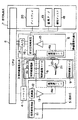
図2に示すように、磁気共鳴撮像装置は、静磁場発生磁石2、傾斜磁場発生系3、シーケンサ4、送信系5、受信系6、信号処理系7、及び中央処理装置(CPU)8等を備えて構成される。静磁場発生磁石2は、被検体1が置かれる空間に均一な静磁場を発生させるものである。その静磁場の方向は、通常、被検体1の体軸方向又は体軸に直交する方向である。また、静磁場発生磁石2は、永久磁石又は常電導あるいは超電導磁石を用いて形成されている。この静磁場発生磁石2に囲まれる静磁場空間内に傾斜磁場発生系3の傾斜磁場コイル9、送信系5の高周波コイル14a、受信系6の高周波コイル14bが設置されている。傾斜磁場発生系3は、直交3軸(X、Y、Z)方向の傾斜磁場を発生する傾斜磁場コイル9と、その傾斜磁場コイル9の駆動電流を供給する傾斜磁場電源10を有して構成されている。傾斜磁場電源10は、シーケンサ4の命令に従って直交3軸(X、Y、Z)方向の傾斜磁場Gx、Gy、Gzを被検体1に印加するようになっている。この傾斜磁場の与え方によって断層像のスライス面を設定することができる。
【0017】
シーケンサ4は、CPU8の制御により動作し、被検体1の生体組織を構成する原子の原子核に核磁気共鳴を起こさせる高周波磁場パルスを、ある所定のパルスシーケンスと称される撮像シーケンスに従って繰り返し印加するものである。また、傾斜磁場発生系3、送信系5、受信系6等に命令を送り、断層像を撮像するのに必要な制御を実行するものである。
【0018】
送信系5は、シーケンサ4の制御により被検体1の生体組織を構成する原子核に核磁気共鳴を起こさせるために高周波磁場パルスを照射するもので、高周波発振器11、変調器12、高周波増幅器13及び高周波コイル14aを有して構成されている。そして、送信系5は、シーケンサ4の命令に従って、高周波発振器11から出力される高周波パルスを変調器12で振幅変調し、さらに高周波増幅器13で増幅した後、高周波照射コイル14aに供給して高周波磁場パルス(RFパルス)を被検体1に照射するようになっている。
【0019】
受信系6は、被検体1の生体組織の原子核の核磁気共鳴により放出されるエコー信号(NMR信号)を検出するもので、受信側の高周波コイル14b、増幅器15、直交位相検波器16及びA/D変換器17を有して構成される。高周波コイル14bにより受波された磁気共鳴信号は増幅器15で増幅され、直交位相検波器16で検波された後、A/D変換器17でディジタル信号の計測データに変換される。なお、シーケンサ4の制御によるタイミングで直交位相検波器16によりサンプリングされた二系列の計測データは、信号処理系7に送られる。なお、受信系6を複数系統設け、それぞれの受信コイル(高周波コイル)により受信した信号を合成して、画像の再構成を行なうことによりS/N比を向上して、あるいは視野の広い撮像を可能にすることができる。
【0020】
信号処理系7は、CPU8、磁気ディスク18、磁気テープ19及びCRTなどのディスプレイ20を有して構成される。CPU8は、受信系6から入力される計測データをフーリエ変換処理を含む画像再構成処理を行い、任意断面の信号強度分布あるいは所定の処理をした画像を作成して、ディスプレイ20に断層像として表示するようになっている。磁気ディスク18及び磁気テープ19は、CPU8により再構成された画像のデータを記録する。ディスプレイ20は、磁気ディスク18及び磁気テープ19に格納されている画像データを映像化して断層像として表示する。また、信号処理系7は、CPU8の機能として、画像データに対する差分処理及び重み付けを行なう機能を備えている。これらの処理の選択及び設定は、CPU8の入力手段(図示せず)を介して行なう。また、ディスプレイ20は、信号処理系7の機能に対応して、通常の画像に代えて、あるいは通常の画像に加えて、差分画像あるいは累積加算画像を表示する機能を備えている。
【0021】
本実施形態では、本発明の特徴である被検体1の体内に挿入される侵襲デバイスであるカテーテル21を追跡するトラッキング機能と、追跡結果をディスプレイ20の画像に表示して術者の挿入操作を誘導するナビゲーション機能を、CPU8に備えている。また、カテーテルの描画性を向上するため、カテーテル21には2個の受信コイル22a、22bが設けられており、それらにより受信されたエコー信号は、受信系23を介してCPU8に取り込まれ、画像再構成などの処理において受信系6の画像と合成されるようになっている。
【0022】
次に、上記実施形態の磁気共鳴撮像装置を用いてカテーテル21の追跡と誘導に係る構成について、動作とともに説明する。図3に、カテーテル21の模式図を示す。本実施形態のカテーテル21は、血管内に挿入可能な円筒状に形成され、その先端部に間隔を空けて2つの受信コイル22a、22bが埋め込まれている。受信コイル22a、22bの間隔は、典型的には、3〜5cmである。なお、受信コイル22a、22bにより受信されるエコー信号は図示していない信号線を通して受信系23に伝送されるようになっている。
【0023】
被検体1を、磁気共鳴撮像装置の静磁場内の測定空間に配置し、図4に示すように、カテーテル21を血管25内を通して必要な治療部位にまで挿入する。個の挿入過程で、例えば、図5に示すマルチショットEPI法による撮像シーケンスにしたがってMR画像を取得する。図5は上から順に、高周波パルスRF、スライス傾斜磁場Gs、位相エンコード傾斜磁場Gp、リードアウト傾斜磁場Gr、エコー信号Signalを示している。そして、横軸は時間を示し、縦軸は強度を表わしている。図示のように、この撮像シーケンスは、スライス傾斜磁場パルス102を印加しながら高周波パルスRF101により励起する。この高周波パルスRF101は90°以下の適当なフリップ角α°である。次いで、位相エンコード傾斜磁場パルス103とリードアウト方向の傾斜磁場パルス104を印加後、リードアウト傾斜磁場パルス105、106、107を反転しながら繰り返し印加して、複数のエコー信号108、109、110を計測する。また、リードアウト傾斜磁場パルス105と106の間及びリードアウト傾斜磁場パルス106と107間に、位相エンコード方向にブリップ111、112を印加してそれらのエコー信号の位相エンコードをずらすようにしている。このような撮像シーケンスを繰り返し時間TRで繰り返し、1枚の画像を構成するのに必要なエコー信号を計測する。いま、TRを10msとし、エコー間隔TEが4ms、FOVが260mm、読み出し方向のデータ数が128、位相エンコード量が120、ショット数が40、エコートレイン数が3(図6の108〜110)と設定すると、1枚の2次元画像の更新時間を約0.4秒(10×120/3=400ms)にすることができる。続いて、スライス傾斜磁場パルス202及び位相エンコード傾斜磁場パルス203を印加するとともにリードアウト方向の傾斜磁場パルス204を印加して、次の画像を取得する撮像シーケンスを繰返す。
【0024】
このようなEPI撮像シーケンスを繰り返し実行し、計測されるエコー信号をフーリエ変換等の画像再構成を行なって2次元又は3次元の画像を取得する。その間、信号処理系7は、各エコー信号のデータを各フレームメモリに格納し、3次元(3D)撮像においては最大値投影(MIP)処理を行ない、時系列画像を連続的に表示する。
【0025】
次に、上述のようにして撮像されるMR画像に基づいて、カテーテル21の位置及び進行方向を検出する一実施形態を説明する。まず、撮像領域内にカテーテル21が存在する場合、図4のような2次元画像が表示される。しかし、2次元画像1枚では、カテーテル21の方向は分からない。そこで、本実施形態では、図5の撮像シーケンスを用いて、まず3軸断面、例えば、X軸、Y軸、Z軸を含む3断面をスライス軸として撮像する。この撮像に要する時間は、前述例では、0.4秒×3断面=1.2秒である。このようにして撮像されたカテーテル21を含む画像の概念を表わす斜視図を図1に示す。図1において、(A)はZ軸に沿った断層像であるTRS像31、(B)はY軸に沿った断層像であるSAG像32、(C)はX軸に沿った断層像であるCOR像33を示す。それらの図は、撮像領域のスライス厚みを考慮して示している。それらの図に示すように、得られる画象において、カテーテル21の受信コイル22a、22bに対応する部位が、それぞれの画像に特異点P1、P2として、他の部位とは著しく異なる輝度の画像として表示される。この3軸断面像に基いて、CPU8はカテーテルの位置及び進行方向を検出する。例えば、各画像における特異点P1と特異点P2を結ぶ直線が各軸X、Y、Zと成す傾きθx、θy、θzを幾何学的に算出し、それらの角度を合成して3次元的な進行方向を求めることができる。なお、3次元の進行方向を求める際は、周知の極座標系又は円柱座標系を用いるのが便利である。また、図中に矢印で示すカテーテルの全体的な進行方向は、時系列的に以前に撮像された画像比較して検出する。
【0026】
このように、本実施形態では、撮像スキャンと同一の撮像シーケンスにより2次元のI−MRI画像の3軸断面像を撮像しながら、それらの画像からカテーテルの位置と進行方向を3次元で検出でき、かつ1.2秒間隔で検出できるから、リアルタイム性に優れたナビゲーションを実現することができる。つまり、検出されたカテーテルの位置と進行方向に従ってCPU8により、例えばスライス位置及びスライス方向等の撮像条件を自動的に変更する指令をシーケンサ4に出力することにより、画像上でカテーテルを見失うことなく目標部位まで誘導することができる。
【0027】
なお、カテーテルの進行方向が大きく変化しない状態の場合は、3軸の断面像を撮像しなくてもカテーテルを見失うことが少ない。この場合は、2軸断面像に基いてカテーテルの位置と進行方向を検出するようにすることにより、検出時間を短縮して、一層リアルタイム性を向上できる。また、3軸断面像を用いていることにより、1つの軸断面像において侵襲デバイスを検出していれば、その位置情報をフィードバックして次の撮像シーケンスによる撮像部位を修正して、追従性を向上できる。つまり、侵襲デバイスを全く見失ってしまうことはなく、おおよその位置がわかっていれば、軸断面像で詳細な位置が分かってしまう。
【0028】
次に、3次元のI−MRI画像を撮像しながらカテーテル21の位置及び進行方向を検出する本発明の他の実施形態を図6〜図8を用いて説明する。図6はカテーテルを含む対象部位の3次元撮像例であり、カテーテル21が血管25内に挿入されている状態を模式的に示している。この3次元画像の画像データに基づいてCPU8において3軸断面の投影処理を行ない、その最大値画素により画像を構成する最大値投影処理(MIP)を行なう。これにより、図7(A)、(B)、(C)に示すCOR像41、SAG像42、TRS像43を得る。また、同図(D)は、カテーテル挿入前に撮像しておいた対象部位を含む断層像に、検出したカテーテルの特異点P1、P2を重ねて表示した合成像44の例である。なお、これらの画像は、MPR(Multi Planar Projection)像である。
【0029】
CPU8は、図7のCOR像41、SAG像42、TRS像43に基いて、カテーテルの位置及び進行方向を検出する。例えば、図8(A)、(B)に示すように、各画像における特異点P1と特異点P2を結ぶ直線が各軸X、Y、Zと成す傾きθx、θy、θzを幾何学的に算出し、それらの角度を合成して3次元的な進行方向S(θx、θy、θz)を求めることができる。ここでは、わかり易いために直交座標系を用いて説明したが、一般には3次元の進行方向を求める際、周知の極座標系を用いるのが便利である。
【0030】
この実施形態の場合も、3次元によるI−MRI撮像のスラブ枚数(スライス枚数)を3枚に設定すれば、前述の例と同様、1.2秒ごとにカテーテルのMIP画像及び位置、進行方向を連続的に求めて表示することができる。また、必要に応じて、カテーテルの進んだ距離や進行速度を求めて画像に表示してもよい。
【0031】
また、利用者が入力手段を介してCPU8に、撮像シーケンスのTR/TE等のパラメータ、スライス方向、スラブ枚数、その他の条件を可変設定できるようにすれば、I−MRI中に測定部位や状況判断により、例えば好みのスライス方向やコントラストのナビゲーション画像を表示させることができる。
【0032】
また、以上の説明では、カテーテルの位置及び進行方向を検出することを中心に説明したが、本発明はこれに止まるものではなく、利用者の設定に応じて、自動的に撮像位置を変えて、カテーテルを追従しながら撮像するナビゲーション撮像手段を備えることができる。つまり、検出されたカテーテルの位置と進行方向を用いて、目標部位とカテーテルとを含む撮像断面又は撮影領域に変更するため、撮像シーケンスの傾斜磁場条件を変えるナビゲーション手段を設ける。この場合、従来例のようにカテーテル位置検出のための撮像をすることなく、組織画像の撮像を連続的に行ない、その画像情報をフィードバックしてカテーテルの位置と進行方向を検出することができる。そのため、撮像時間及び画像処理の時間を短縮することができるから、カテーテルを目標部位に誘導するナビゲーションのリアルタイム性を改善できる。特に、手術前に目標部位周囲の組織画像を撮像して記憶しておき、この組織画像にカテーテルのトラッキング画像を重ねて表示することにより、カテーテルを目標部位に誘導するナビゲーションのリアルタイム性を確保しつつ、I−MR画像の視認性を向上できる。
【0033】
上記の実施形態において、カテーテルに埋め込む受信コイルは、小型ループ状のコイルでも、線状のコイルでもよい。また、受信コイルに代えて、磁性体などの低信号材料又は高信号材料からなるマーカをカテーテルに取り付けたり、カテーテルの樹脂に混入したものでもよい。要は、カテーテルの長手方向に間隔を離してMR画像で他の部分と区別できる特異な画像となる少なくとも2つの特異点を設ければよい。
【0034】
また、侵襲デバイスとしてカテーテルを例に説明したが、これに限らず、穿刺針などのような体内に挿入してもといるデバイスのトラッキングおよびナビゲーションに適用できる。
【0035】
【発明の効果】
以上述べたように、本発明によれば、トラッキング対象の侵襲デバイスを見失うことなく追従でき、リアルタイム性に優れたナビゲーションを実現することができる。
【図面の簡単な説明】
【図1】本発明の特徴に係る3軸断面像を用いて侵襲デバイスの一例であるカテーテルの進入方向を検出する一実施形態を説明する模式図である。
【図2】本発明を適用することができる磁気共鳴撮像装置の全体のブロック構成図である。
【図3】カテーテルの一例を示す斜視図である。
【図4】血管内に挿入されたカテーテルの状態を示す模式図である。
【図5】本発明に用いる撮像シーケンスの一例を示す図である。
【図6】カテーテルを含む対象部位の3次元撮像により得られるI−MR像を模式的に示す斜視図である。
【図7】図6の3次元画像を最大値投影処理して得られるCOR像、SAG像、TRS像及びカテーテルの特異点P1、P2を重ねて表示した合成画像の一例である。
【図8】3次元撮像の画像を処理してより得られたCOR像、SAG像、TRS像に基いてカテーテルの位置及び進入方向を検出する一実施形態を説明する模式図である。
【符号の説明】
21 カテーテル
22a、22b 受信コイル
25 血管
31 TRS像
32 SAG像
33 COR像[0001]
BACKGROUND OF THE INVENTION
The present invention relates to a magnetic resonance imaging apparatus, and more particularly to a technique for controlling an imaging surface by following the movement of an invasive device such as a catheter inserted into a living body of a subject while performing continuous imaging.
[0002]
[Prior art]
A magnetic resonance imaging (MRI) apparatus excites nuclei at a desired measurement site in a living body, and forms an image of the measurement site in the living body based on a nuclear magnetic resonance signal (NMR signal) generated by the excitation. This device is used for diagnosis. Usually, to excite nuclei, a high frequency magnetic field pulse is irradiated in a state where a uniform static magnetic field is applied to a living body. In addition, in order to obtain a two-dimensional tomographic image of the measurement site, a gradient magnetic field having a gradient in the orthogonal three-axis directions is applied to give positional information of the two-dimensional space to the NMR signal. A control procedure for capturing an MR image of a desired part by controlling the timing of irradiation of these high-frequency magnetic field pulses, application of a gradient magnetic field, sampling of an NMR signal, and the strength of the gradient magnetic field is called a pulse sequence. It is determined by the imaging sequence.
[0003]
As such an imaging sequence, in addition to basic methods such as a spin echo method and a gradient echo method, an echo planer (EPI) method and a fast spin echo (FSE) method are used as a high-speed imaging method. , Etc. are proposed. This FSE method is a method realized as a practical high-speed sequence having an image quality close to that of the conventional SE method by dividing the conventional RARE method into a plurality of sequence sequences. Here, the RARE (rapid acquisition with relaxation enhancement) method is a method in which a large amount of echo signals (NMR signals) are generated by repeating inversion by radio frequency (RF) of transverse magnetization generated by excitation by a 90 ° pulse. This is an imaging sequence in which a multi-echo method for generating the image is applied and different phase encodings are given to the respective echo signals so that one image can be obtained at high speed. On the other hand, the EPI method is a method of acquiring a plurality of echo signals with one excitation pulse by inverting the readout gradient magnetic field at high speed without using RF inversion. According to this EPI method, high-speed imaging of several tens of ms is possible, but it is extremely sensitive to non-uniform static magnetic fields.
[0004]
By applying these high-speed imaging sequences, a real-time dynamic imaging method called fluoroscopy (perspective imaging) is being applied to clinical practice. Fluoroscopy repeats short-time imaging of about 1 second or less and real-time image reconstruction, and is used to visualize the dynamics of internal tissues and to insert an invasive device such as a catheter from outside into the body as if it were X-ray fluoroscopic imaging. It can be used for grasping the position of. In particular, recently, in order to minimize the invasiveness to a patient, an application in intraoperative imaging generally called an interventional MRI (I-MRI) is being performed.
[0005]
The most promising application of fluoroscopy in I-MRI is an imaging means for guiding an invasive device such as a puncture needle or a catheter to an affected area. Since normal two-dimensional imaging cannot detect the three-dimensional position of the catheter, it is difficult to obtain information such as the traveling direction. In this regard, a method for three-dimensionally detecting the position and direction of the catheter is described in the literature “Magnetic Resonance in Medicine 44, pp. 56-65 (2000), Active MR Guidance of Interventional Devices. With Target-Navigation ”. According to this, a plurality of RF receiving coils are embedded at intervals in the longitudinal direction of the catheter, the catheter approaching direction is detected based on the MR images of those coils, and the detected catheter approaching direction and the affected part, etc. MR images for navigation are performed by automatically determining a scan section including the position of the tissue. In other words, the imaging section is determined so as to always include the target tissue and the catheter, so that the catheter is not lost.
[0006]
[Problems to be solved by the invention]
However, the active guide method of the catheter described in the above document detects the position and direction of the catheter after imaging three orthogonal cross sections (for example, X, Y, and Z cross sections) twice, and then the target tissue. The actual scanning imaging is performed by determining the imaging section including the catheter and the catheter. That is, since the catheter tracking and the navigation image are divided into two stages and imaged by the time division method, there is a time lag until the catheter is detected, and there is a problem in the real-time property as navigation, which is not practical.
[0007]
An object of the present invention is to realize navigation with excellent real-time performance that can follow an invasive device to be tracked without losing sight.
[0008]
[Means for Solving the Problems]
The present invention solves the above problems by the following means. First, according to the present invention, an imaging sequence for collecting an echo signal generated by excitation by applying a high-frequency pulse and a gradient magnetic field to a subject placed in a static magnetic field space and collecting the echo signals generated by the excitation is collected. A magnetic resonance imaging apparatus that reconstructs a two-dimensional or three-dimensional image of a desired part of the subject based on an echo signal and continuously displays the reconstructed image on a display is used as a basic means.
[0009]
A feature of the present invention is based on a reconstructed image using an invasive device provided with at least two singular points that are separated from each other in the MR image at a distance in the longitudinal direction of the invasive device and become a unique image. In addition, a singular point of the invasive device to be inserted into the subject is detected, and a invasive device detecting means for detecting the position of the invasive device and the three-dimensional approach direction by obtaining the direction of the straight line connecting the two singular points is provided. There is.
[0010]
In the case of an imaging sequence that captures a two-dimensional image, the invasive device detection means can obtain the direction of a straight line connecting singular points by the three-axis cross-sectional image by capturing orthogonal three-axis cross-sectional images. Here, the triaxial cross-sectional image is, for example, a horizontal cross-section (COR), a vertical vertical cross-section (SAG), and a vertical cross-section (TRS) of a lying patient. By the way, if the approach direction does not change, it is possible to track with an orthogonal biaxial cross-sectional image, and there is no need to capture a triaxial cross-sectional image. Therefore, the imaging time can be shortened by switching the imaging sequence. In addition, by using a triaxial cross-sectional image, if an invasive device is detected in one axial cross-sectional image, the position information is fed back to correct the imaging region by the next imaging sequence, thereby improving the followability. It can be improved. That is, the invasive device is not lost at all, and if the approximate position is known, the detailed position can be understood from the axial cross-sectional image.
[0011]
In the case of an imaging sequence for imaging a three-dimensional image, the invasive device detection means can determine the direction of a straight line connecting singular points from a projection image obtained by projecting the three-dimensional image onto a plane including three orthogonal axes. The projection image can be obtained by a known maximum value projection process (MIP).
[0012]
As described above, according to the present invention, since the approach direction of the invasive device that changes three-dimensionally can be detected, the invasive device to be tracked can be detected even if the approach direction of the invasive device changes three-dimensionally. Follow without losing sight. In addition, since the invasive device is tracked by the same imaging sequence as the imaging scan, navigation with excellent real-time characteristics can be realized.
[0013]
In addition, the singular point is formed by, for example, embedding a small RF receiving coil in the distal end portion of the invasive device, or a marker made of a low signal material such as a magnetic material or a high signal material is mixed in the resin of the catheter. Can be formed.
[0014]
The magnetic resonance imaging apparatus of the present invention uses the position or traveling direction of the invasive device detected by the invasive device detection means to change to an imaging cross section or imaging region including the target site for invasive device guidance and the invasive device. Navigation means for changing the gradient magnetic field condition of the imaging sequence can be provided. In this case, without taking an image for detecting the position of the invasive device as in the conventional example, the tissue image and the blood vessel image are continuously captured, and the image information is fed back to detect the position and the traveling direction of the invasive device. can do. According to this, since the imaging time and the image processing time can be shortened, the real-time property of navigation for guiding the invasive device to the target site can be improved. In this case, a tissue image and a blood vessel image around the target site are captured and stored before surgery, and a tracking image of the invasive device is superimposed on the image to display the navigation image for guiding the invasive device to the target site. Real-time performance can be further improved.
[0015]
[Embodiment]
Hereinafter, an embodiment of the present invention will be described with reference to FIGS. FIG. 1 is a schematic diagram illustrating an embodiment for detecting a catheter approach direction which is an example of an invasive device using a triaxial cross-sectional image according to a feature of the present invention. FIG. 2 is an overall block diagram of a magnetic resonance imaging apparatus to which the present invention can be applied. FIG. 3 is a perspective view showing an example of a catheter. FIG. 4 is a schematic diagram showing a state of the catheter inserted into the blood vessel. FIG. 5 is a diagram showing an example of an imaging sequence used in the present invention.
[0016]
As shown in FIG. 2, the magnetic resonance imaging apparatus includes a static magnetic
[0017]
The sequencer 4 operates under the control of the
[0018]
The transmission system 5 irradiates a high frequency magnetic field pulse to cause nuclear magnetic resonance to occur in the nucleus constituting the living tissue of the subject 1 under the control of the sequencer 4, and includes a high frequency oscillator 11, a modulator 12, a
[0019]
The receiving system 6 detects an echo signal (NMR signal) emitted by nuclear magnetic resonance of the nucleus of the living tissue of the subject 1, and receives the high-
[0020]
The signal processing system 7 includes a
[0021]
In the present embodiment, the tracking function for tracking the
[0022]
Next, the configuration related to the tracking and guidance of the
[0023]
The subject 1 is placed in the measurement space in the static magnetic field of the magnetic resonance imaging apparatus, and the
[0024]
Such an EPI imaging sequence is repeatedly executed, and a two-dimensional or three-dimensional image is acquired by performing image reconstruction such as Fourier transform on the measured echo signal. Meanwhile, the signal processing system 7 stores the data of each echo signal in each frame memory, performs maximum value projection (MIP) processing in three-dimensional (3D) imaging, and continuously displays time-series images.
[0025]
Next, an embodiment for detecting the position and traveling direction of the
[0026]
As described above, in the present embodiment, the three-dimensional cross-sectional image of the two-dimensional I-MRI image is captured by the same imaging sequence as the imaging scan, and the catheter position and traveling direction can be detected in three dimensions from these images. In addition, since it can be detected at intervals of 1.2 seconds, navigation with excellent real-time performance can be realized. That is, the
[0027]
In the state where the traveling direction of the catheter does not change greatly, it is less likely that the catheter will be missed without taking a three-axis cross-sectional image. In this case, the detection time can be shortened and the real-time property can be further improved by detecting the position and traveling direction of the catheter based on the biaxial cross-sectional image. In addition, by using a triaxial cross-sectional image, if an invasive device is detected in one axial cross-sectional image, the position information is fed back to correct the imaging region by the next imaging sequence, thereby improving the followability. It can be improved. In other words, the invasive device is not lost at all, and if the approximate position is known, the detailed position is known from the axial cross-sectional image.
[0028]
Next, another embodiment of the present invention for detecting the position and traveling direction of the
[0029]
The
[0030]
Also in this embodiment, if the number of three-dimensional I-MRI imaging slabs (number of slices) is set to three, the MIP image of the catheter, the position, and the traveling direction every 1.2 seconds as in the above example. Can be continuously obtained and displayed. Moreover, you may obtain | require and display on the image the distance which the catheter advanced, and the advancing speed as needed.
[0031]
Also, if the user can variably set parameters such as TR / TE of the imaging sequence, slice direction, number of slabs, and other conditions to the
[0032]
Further, in the above description, the description has focused on detecting the position and traveling direction of the catheter, but the present invention is not limited to this, and the imaging position is automatically changed according to the user's setting. Further, navigation imaging means for imaging while following the catheter can be provided. That is, navigation means for changing the gradient magnetic field condition of the imaging sequence is provided in order to change the imaging section or imaging region including the target site and the catheter using the detected position and traveling direction of the catheter. In this case, the tissue image can be continuously imaged without imaging for catheter position detection as in the conventional example, and the image information can be fed back to detect the catheter position and traveling direction. Therefore, since the imaging time and the time for image processing can be shortened, the real-time property of navigation for guiding the catheter to the target site can be improved. In particular, a tissue image around the target site is captured and stored before surgery, and the tracking image of the catheter is superimposed on the tissue image and displayed, thereby ensuring real-time navigation for guiding the catheter to the target site. Meanwhile, the visibility of the I-MR image can be improved.
[0033]
In the above embodiment, the receiving coil embedded in the catheter may be a small loop coil or a linear coil. Further, instead of the receiving coil, a marker made of a low signal material or a high signal material such as a magnetic material may be attached to the catheter or mixed with the catheter resin. In short, it is only necessary to provide at least two singular points that form a peculiar image that can be distinguished from other parts in the MR image with an interval in the longitudinal direction of the catheter.
[0034]
Further, the catheter has been described as an example of the invasive device. However, the present invention is not limited to this, and the present invention can be applied to tracking and navigation of a device that is inserted into the body such as a puncture needle.
[0035]
【The invention's effect】
As described above, according to the present invention, it is possible to follow the invasive device to be tracked without losing sight, and to realize navigation with excellent real-time properties.
[Brief description of the drawings]
FIG. 1 is a schematic diagram for explaining an embodiment in which a catheter approach direction, which is an example of an invasive device, is detected using a triaxial cross-sectional image according to a feature of the present invention.
FIG. 2 is an overall block diagram of a magnetic resonance imaging apparatus to which the present invention can be applied.
FIG. 3 is a perspective view showing an example of a catheter.
FIG. 4 is a schematic diagram showing a state of a catheter inserted into a blood vessel.
FIG. 5 is a diagram showing an example of an imaging sequence used in the present invention.
FIG. 6 is a perspective view schematically showing an I-MR image obtained by three-dimensional imaging of a target region including a catheter.
7 is an example of a composite image in which a COR image, a SAG image, a TRS image, and singular points P1 and P2 of a catheter obtained by performing a maximum value projection process on the three-dimensional image of FIG. 6 are displayed in an overlapping manner.
FIG. 8 is a schematic diagram for explaining an embodiment for detecting a catheter position and an approach direction based on a COR image, a SAG image, and a TRS image obtained by processing an image of three-dimensional imaging.
[Explanation of symbols]
21
Claims (8)
Priority Applications (3)
| Application Number | Priority Date | Filing Date | Title |
|---|---|---|---|
| JP2001073623A JP3911602B2 (en) | 2001-03-15 | 2001-03-15 | Magnetic resonance imaging device |
| US10/469,566 US20040092813A1 (en) | 2001-03-01 | 2002-02-28 | Magnetic resonance imaging apparatus |
| PCT/JP2002/001851 WO2002069800A1 (en) | 2001-03-01 | 2002-02-28 | Magnetic resonance imging apparatus |
Applications Claiming Priority (1)
| Application Number | Priority Date | Filing Date | Title |
|---|---|---|---|
| JP2001073623A JP3911602B2 (en) | 2001-03-15 | 2001-03-15 | Magnetic resonance imaging device |
Publications (3)
| Publication Number | Publication Date |
|---|---|
| JP2002272700A JP2002272700A (en) | 2002-09-24 |
| JP2002272700A5 JP2002272700A5 (en) | 2005-09-29 |
| JP3911602B2 true JP3911602B2 (en) | 2007-05-09 |
Family
ID=18931020
Family Applications (1)
| Application Number | Title | Priority Date | Filing Date |
|---|---|---|---|
| JP2001073623A Expired - Fee Related JP3911602B2 (en) | 2001-03-01 | 2001-03-15 | Magnetic resonance imaging device |
Country Status (1)
| Country | Link |
|---|---|
| JP (1) | JP3911602B2 (en) |
Families Citing this family (6)
| Publication number | Priority date | Publication date | Assignee | Title |
|---|---|---|---|---|
| JP4443079B2 (en) | 2001-09-13 | 2010-03-31 | 株式会社日立メディコ | Magnetic resonance imaging apparatus and RF receiving coil for magnetic resonance imaging apparatus |
| JP3996438B2 (en) * | 2002-05-16 | 2007-10-24 | 株式会社日立メディコ | Catheter RF antenna |
| WO2006080020A2 (en) | 2005-01-31 | 2006-08-03 | Mediguide Ltd. | Reducing em interference during medical navigation |
| US7236567B2 (en) * | 2005-03-24 | 2007-06-26 | Siemens Aktiengesellschaft | Method and apparatus for synchronizing operation of an x-ray system and a magnetic system |
| US8543186B2 (en) | 2007-03-01 | 2013-09-24 | Kabushiki Kaisha Toshiba | Magnetic resonance imaging apparatus and magnetic resonance imaging method |
| EP2508907A1 (en) | 2011-04-07 | 2012-10-10 | Koninklijke Philips Electronics N.V. | Magnetic resonance guidance of a shaft to a target zone |
-
2001
- 2001-03-15 JP JP2001073623A patent/JP3911602B2/en not_active Expired - Fee Related
Also Published As
| Publication number | Publication date |
|---|---|
| JP2002272700A (en) | 2002-09-24 |
Similar Documents
| Publication | Publication Date | Title |
|---|---|---|
| US5307808A (en) | Tracking system and pulse sequences to monitor the position of a device using magnetic resonance | |
| EP1790286B1 (en) | Magnetic resonance imaging apparatus and method | |
| US9305376B2 (en) | Magnetic resonance imaging apparatus and method of acquiring functional image | |
| US7027854B2 (en) | Magnetic resonance imaging utilizing a microcoil | |
| WO2003005902A1 (en) | Endoscopic image pickup method and magnetic resonance imaging device using the same | |
| JP5074211B2 (en) | Magnetic resonance imaging system | |
| US6876198B2 (en) | Magnetic resonance imaging system | |
| US20040039280A1 (en) | MR-guided breast tumor ablation and temperature imaging system | |
| JP3976845B2 (en) | Magnetic resonance imaging system | |
| US20040092813A1 (en) | Magnetic resonance imaging apparatus | |
| JP3911602B2 (en) | Magnetic resonance imaging device | |
| JP4349647B2 (en) | Magnetic resonance imaging system | |
| WO2016021440A1 (en) | Magnetic resonance imaging device | |
| JP3514547B2 (en) | Magnetic resonance imaging system | |
| JP3972236B2 (en) | Magnetic resonance imaging device | |
| JP4201089B2 (en) | Magnetic resonance imaging apparatus and multi-station CE-MRA method | |
| JP4822834B2 (en) | Magnetic resonance imaging system | |
| JP2000316830A (en) | Magnetic resonance imaging method and magnetic resonance imaging device using the same | |
| JP4219028B2 (en) | Magnetic resonance imaging system | |
| JP6912341B2 (en) | Magnetic resonance imaging device, device position detection method using it, and image-guided intervention support device | |
| JP3638593B2 (en) | Magnetic resonance tracking device | |
| JP4118119B2 (en) | Magnetic resonance imaging system | |
| JP2002143121A (en) | Magnetic resonance imaging equipment | |
| JP2003052664A (en) | Apparatus and method for photographing magnetic resonance image | |
| JPH05123314A (en) | Multislice image pick-up method in magnetic resonance imaging device |
Legal Events
| Date | Code | Title | Description |
|---|---|---|---|
| A521 | Written amendment |
Free format text: JAPANESE INTERMEDIATE CODE: A523 Effective date: 20050425 |
|
| A621 | Written request for application examination |
Free format text: JAPANESE INTERMEDIATE CODE: A621 Effective date: 20050425 |
|
| A131 | Notification of reasons for refusal |
Free format text: JAPANESE INTERMEDIATE CODE: A131 Effective date: 20060926 |
|
| A521 | Written amendment |
Free format text: JAPANESE INTERMEDIATE CODE: A523 Effective date: 20061127 |
|
| TRDD | Decision of grant or rejection written | ||
| A01 | Written decision to grant a patent or to grant a registration (utility model) |
Free format text: JAPANESE INTERMEDIATE CODE: A01 Effective date: 20061226 |
|
| A61 | First payment of annual fees (during grant procedure) |
Free format text: JAPANESE INTERMEDIATE CODE: A61 Effective date: 20070116 |
|
| R150 | Certificate of patent or registration of utility model |
Free format text: JAPANESE INTERMEDIATE CODE: R150 |
|
| FPAY | Renewal fee payment (event date is renewal date of database) |
Free format text: PAYMENT UNTIL: 20100209 Year of fee payment: 3 |
|
| FPAY | Renewal fee payment (event date is renewal date of database) |
Free format text: PAYMENT UNTIL: 20110209 Year of fee payment: 4 |
|
| FPAY | Renewal fee payment (event date is renewal date of database) |
Free format text: PAYMENT UNTIL: 20110209 Year of fee payment: 4 |
|
| FPAY | Renewal fee payment (event date is renewal date of database) |
Free format text: PAYMENT UNTIL: 20120209 Year of fee payment: 5 |
|
| FPAY | Renewal fee payment (event date is renewal date of database) |
Free format text: PAYMENT UNTIL: 20130209 Year of fee payment: 6 |
|
| FPAY | Renewal fee payment (event date is renewal date of database) |
Free format text: PAYMENT UNTIL: 20140209 Year of fee payment: 7 |
|
| LAPS | Cancellation because of no payment of annual fees |