JP3902664B2 - Personal identification - Google Patents
Personal identification Download PDFInfo
- Publication number
- JP3902664B2 JP3902664B2 JP50033898A JP50033898A JP3902664B2 JP 3902664 B2 JP3902664 B2 JP 3902664B2 JP 50033898 A JP50033898 A JP 50033898A JP 50033898 A JP50033898 A JP 50033898A JP 3902664 B2 JP3902664 B2 JP 3902664B2
- Authority
- JP
- Japan
- Prior art keywords
- light
- user
- eye
- image
- optical path
- Prior art date
- Legal status (The legal status is an assumption and is not a legal conclusion. Google has not performed a legal analysis and makes no representation as to the accuracy of the status listed.)
- Expired - Fee Related
Links
Images


Classifications
-
- G—PHYSICS
- G07—CHECKING-DEVICES
- G07C—TIME OR ATTENDANCE REGISTERS; REGISTERING OR INDICATING THE WORKING OF MACHINES; GENERATING RANDOM NUMBERS; VOTING OR LOTTERY APPARATUS; ARRANGEMENTS, SYSTEMS OR APPARATUS FOR CHECKING NOT PROVIDED FOR ELSEWHERE
- G07C9/00—Individual registration on entry or exit
-
- A—HUMAN NECESSITIES
- A61—MEDICAL OR VETERINARY SCIENCE; HYGIENE
- A61B—DIAGNOSIS; SURGERY; IDENTIFICATION
- A61B3/00—Apparatus for testing the eyes; Instruments for examining the eyes
- A61B3/10—Objective types, i.e. instruments for examining the eyes independent of the patients' perceptions or reactions
- A61B3/12—Objective types, i.e. instruments for examining the eyes independent of the patients' perceptions or reactions for looking at the eye fundus, e.g. ophthalmoscopes
- A61B3/1216—Objective types, i.e. instruments for examining the eyes independent of the patients' perceptions or reactions for looking at the eye fundus, e.g. ophthalmoscopes for diagnostics of the iris
-
- G—PHYSICS
- G06—COMPUTING; CALCULATING OR COUNTING
- G06V—IMAGE OR VIDEO RECOGNITION OR UNDERSTANDING
- G06V10/00—Arrangements for image or video recognition or understanding
- G06V10/10—Image acquisition
- G06V10/12—Details of acquisition arrangements; Constructional details thereof
- G06V10/14—Optical characteristics of the device performing the acquisition or on the illumination arrangements
- G06V10/143—Sensing or illuminating at different wavelengths
-
- G—PHYSICS
- G06—COMPUTING; CALCULATING OR COUNTING
- G06V—IMAGE OR VIDEO RECOGNITION OR UNDERSTANDING
- G06V30/00—Character recognition; Recognising digital ink; Document-oriented image-based pattern recognition
- G06V30/10—Character recognition
- G06V30/14—Image acquisition
- G06V30/142—Image acquisition using hand-held instruments; Constructional details of the instruments
-
- G—PHYSICS
- G06—COMPUTING; CALCULATING OR COUNTING
- G06V—IMAGE OR VIDEO RECOGNITION OR UNDERSTANDING
- G06V40/00—Recognition of biometric, human-related or animal-related patterns in image or video data
- G06V40/10—Human or animal bodies, e.g. vehicle occupants or pedestrians; Body parts, e.g. hands
- G06V40/18—Eye characteristics, e.g. of the iris
- G06V40/19—Sensors therefor
-
- G—PHYSICS
- G07—CHECKING-DEVICES
- G07C—TIME OR ATTENDANCE REGISTERS; REGISTERING OR INDICATING THE WORKING OF MACHINES; GENERATING RANDOM NUMBERS; VOTING OR LOTTERY APPARATUS; ARRANGEMENTS, SYSTEMS OR APPARATUS FOR CHECKING NOT PROVIDED FOR ELSEWHERE
- G07C9/00—Individual registration on entry or exit
- G07C9/30—Individual registration on entry or exit not involving the use of a pass
- G07C9/32—Individual registration on entry or exit not involving the use of a pass in combination with an identity check
- G07C9/37—Individual registration on entry or exit not involving the use of a pass in combination with an identity check using biometric data, e.g. fingerprints, iris scans or voice recognition
Description
本発明は、個人識別のための装置および方法に関する。本発明はとくに、前眼房の特徴の像を捕捉し、同時に眼の像を表示することを要求される装置に利用できる。このような装置は、ユーザのアイリス(虹彩)の像を捕捉する認証デバイスで使用することができる。
人の眼の像を捕捉し、同時に人の眼によって見るディスプレイを準備した装置が知られている。例えば、IriScan Inc.ではSystem 2000EACTM認証装置を販売している。別の例には、国際特許出願WO92/05736号で開示された瞳孔計(pupillometer)がある。
前者の装置は、アイリスパターン捕捉ユニットおよび識別コード生成ユニットを含む。アイリスパターン捕捉ユニットは2つの開口をもつハウジングを備えている。赤外線照明源は、第1の開口を通して可視光および赤外線項光を投影して、人の眼を照明するようにされている。開口の中にインストールされたカメラは、視野が第2の開口を通るようにされている。装置を使用するとき、人は、カメラによって見られる像を再生するディスプレイで第2の開口を通してみる。同時に、照明源からの光は人の眼から第2の開口を通ってカメラへ反射される。ディスプレイによって、人は自分の眼の位置を決めることができ、眼に焦点を合わせて、カメラの視野の中心に位置付けできる。
実際には、ユーザはユーザの眼の像の捕捉を成功させるために、デバイスから狭い範囲の距離内に眼を位置付けなければならない。
中心窩眼底スキャナは、欧州特許出願第0 126 549号で開示されている。この装置はスキャニング(走査用)光学系を使用して、眼底(網膜および脈絡膜)を検査するので、複雑で場所を取るものになる。
これらは本発明が扱う2つの問題であり、個々人の眼の虹彩を識別する情報信号を与える識別装置であって、入射窓をもつハウジングと;前記ハウジング上に装着されて、瞳孔の外側領域で前記眼を照明するように動作する照明源と;前記ハウジング内に装着され、前記入射窓と光学的に結合されており、前記眼から反射した前記照明源からの光の入射に応答して前記眼の前眼房の1または複数の特徴を表す像信号を与えるように動作する像捕捉デバイスと;波長選択反射器とを含み;使用時に、可視光が第1の光路に沿って前記波長選択反射器を経て眼へ進み、眼で見ることができる可視像を作り、かつ前記照明源から出射した照明光の前記眼から反射した光が第2の光路に沿って前記波長選択反射器を介して前記像捕捉装置へ進み;前記波長選択反射器が、前記照明光及び前記可視光のうち少なくとも1つを反射するようにされ、前記照明光のうち大部分の波長帯域の光は前記第2の光路に沿って前記像捕捉装置へさらに進み、前記第2の光路へ進む光とは異なる波長帯域の光を主成分とする前記可視光は前記第1の光路に沿って眼へさらに進む識別装置。
本明細書で使用されている用語‘光学的(optical)’および‘光(light)’は電磁放射であり、電磁スペクトルの赤外線部分、可視光線部分、および紫外線部分、すなわち10nm乃至1mmの波長をもつ。
所定のタイプの照明光のほとんどは像捕捉装置に到達するので、本発明には数多くの長所がある。
最初に像捕捉装置ではより多くの光を受取るので、像捕捉装置と関係する光構成の開口を減らすことができる。これは像捕捉装置の焦点深度が増すという結果を生む。したがって、十分に焦点の合った像を作るために眼がこの装置と関連しなければならないという制約が緩和される。
第2に、露出時間を減らして、人を静止させつづける必要を少なくしながら、像を捕捉することができる。
第3に、本発明では、像捕捉装置が応答する光の有効量が比較的に少ない状況で、満足のいく像を捕捉することができる。これは、安全性を考慮すると、眼に向けることができる光が制限されるので効果的である。さらに本発明は、この装置の電力要求を減らすという点でも有益であり、特にバッテリ駆動の可搬式装置に対して効果的である。
当業者は、上述の長所が個々にまたは組合わせて実現できることを認識するであろう。一般的に、像捕捉装置により多くの光を与えることによって生成された像の品質は向上する。
像捕捉装置に入射する所定のタイプの前記ユーザ光の割合が(周知の装置と比較して)増加することにより、性能が幾分向上する。しかしながら、所定のタイプのユーザ光の75%以上が光路に沿って像捕捉装置へ進むことが好ましい。
上述に加えて、可視光が実質的に減衰されずにユーザのところへ進むことができることにより、ディスプレイの見かけ輝度(apparent brightness)が増す。したがって装置が消費する電力量が低減する;これは可搬式装置の特に有益な特徴である。可視光の75%以上が光路に沿ってユーザへ向ってさらに進むことが好ましい。
前眼房の特徴は、アイリス、角膜、強膜、または眼瞼、あるいはこれらを2以上組合わせたものであってもよい。
装置のところへ、ユーザが自分の眼、または他人の目、あるいは動物の眼をもってくるようにしてもよい。その代りにこの装置を適所に固定して、検眼される人がこの装置の位置にしたがって自分の頭を整列させることを要求してもよい。
いくつかの場合において、眼でみることのできる可視像はこの装置を通る視野(視野)であってもよい。他の場合では、表示手段は可視像を準備するか、または既に存在するディスプレイの上に部分的なディスプレイを重ね合わせて、可視像を準備する。これは、装置を使用するときに眼に情報を与えることができるという長所をもつ。別の方法では、ユーザの像捕捉ユニットを動作して、一方で眼でディスプレイ上の情報を観察する。
ディスプレイの1使用例には、像捕捉装置によって受取られる像を示すディスプレイを準備するものがある。人は頭を動かして、捕捉した像の品質を向上することができるので、これは効果的である。
好ましい実施形態では、眼に向けられた可視光と像捕捉装置へ向けられた光とは、異なるスペクトルをもつ。したがって像捕捉装置に向けられた光は電磁スペクトルの可視光領域外にある必要はない。例えば、狭いスペクトル帯域内で光を放出する赤、青、緑のLEDを使用して、ディスプレイを生成することができ、像捕捉装置は、狭いスペクトル帯域外であるが、電磁スペクトルの可視光部分内に含まれる可視光を受取る。
これらの実施形態の有効な変形例では、光学デバイスは前記可視光または前記異なるスペクトル光の何れかを反射するのに効果的な波長選択式反射器を含む。このような反射器は経済的であり、これを使用することによってこの装置の構成要素を都合良く配置することができる。選択は、例えば金属コーティングまたは誘電材料のコーティングから行なうことができる。
照明光は眼に入射するので、所定のタイプの光が実質的に不可視光からなるとき、この装置はさらに使いやすくなる。
好ましくは、所定のタイプの光は実質的に近赤外線(すなわち、700nm乃至3μmの波長をもつ)からなる。まれに高熱の物体が電磁スペクトルの近赤外線領域に著しい量の光を放出して、像を歪ませることがあるので、この構成は好ましい。
光学デバイスが‘ホットミラー’を含むとき、別の長所が得られる。ホットミラーは、実質的に全ての近赤外線光を反射するように動作し、一方で可視光を通すことができるデバイスである。また‘コールドミラー’(実質的に全ての可視光を反射し、近赤外線を通すことができる)を使用できることも当業者に認識されるであろう。
照明源を使用する長所は、像を作るのに使用される光のスペクトルおよび方向の両方を使用できることである。
アイリスの像を捕捉するようにこの装置を設計するとき、特に有効な実施形態を作ることができる。眼に当たる光は不可視光であってもよく、このときこの装置は使いやすくなる。さらに照明光の強度は、像捕捉装置に入射する光量を増加することによって低減することができる。ここでもこの装置はさらに使いやすくなる。
いくつかの実施形態では、この装置はユーザによって動作位置へ運ばれるようにされ、さらに前記像信号から遠隔の装置へ引き出された前記情報信号を送るように動作する伝送デバイスを含む。伝送デバイスは、遠隔の装置と近赤外線、超音波、またはRFで通信するコードレス伝送デバイスであってもよい。この場合光学デバイスの使用は、この装置の電力要求が減らされるのでとくに効果的である。
ここで本発明の特定の実施形態を添付の図面を参照して例示的に記載することにする:
図1は、遠隔地から共用コンピュータへアクセスするようにされているパーソナルコンピュータを示す;
図2は、アイリス結像装置の模式図である;
図3は、結像装置の1つの可能なハードウエアアーキテクチャを示す模式図である;
図4は、像の捕捉および暗号化プロセスのフローチャートを示す;
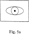
図5aおよび5bは、ユーザが自分の眼を正確にまたは不正確に整列させたディスプレイを示す図である。
図1はユーザのパーソナルコンピュータ(PC)10を示しており、これは標準の入力/出力デバイスおよび関係付けられたインターフェイスに加えて、赤外線受信機22、送信機23、および近赤外線信号インターフェイスカード(図示されていない)をもつ。これらの付加的な構成要素によりユーザのPC10とイメージ捕捉装置12との間のデータ通信が可能になる。
ユーザのPC10はモデム14および遠隔通信ライン16を経て中間のルート設定コンピュータ18へ接続されており、信号をユーザのPC10からサーバ20へルート設定する。サーバ20は、例えば会社に属しており、この会社の有意値(significant value)をもつファイルを含む記憶手段をもってもよい。しかしながらPC10のユーザがその会社の被雇用者であるとき、PC10とサーバ20との間に通信リンクを準備することによって被雇用者が家で働けるようになるという長所をもつ。
図2は、像捕捉装置をさらに詳しく示している。この装置は、通常T字型のハウジング125をもち、このハウジング125は、延在する水平のバレル部分130と、両端部の中間位置でバレル130から下方向にぶら下がっているハンドル部分とをもつ。ハンドル部分は実質的に中空であり、最下端部で閉じている。電荷転送素子(CCD)カメラ135はハンドル部分内側の基部に配置されている。カメラは白黒カメラであり、可視光線および近赤外線光に対してほぼ同じ感度をもつ。CCDカメラ135の出力からバレル130の正面の内側に装着された後部方向に向いている液晶ディスプレイ(LCD)170への接続をとっている(図示されていない)。ハンドル部分はさらに、ハウジング(図2に詳しく記載されている)内に収められた適切な電子回路180を含む。
窓120はバレル130の後部端部に形成されている。アイカップ115はバレルの後部端部に取付けられ窓120を取り囲んでいる。アイカップ115は、この装置へ入射する周辺光の量を最小にする手段として、およびユーザの眼を窓120と整列させる手段として働く。
‘ホットミラー’145(例えば、Ealing Optics of Greylaine Rd, Watford, U.K.によってカタログ番号35−6681で販売されている)は、CCDカメラのすぐ上に配置されている。ミラー145は45°でバレル130の長手方向軸に対して下方向前方に傾斜している。このミラーは、絶縁体材料で下側をコーティングしたガラススライドから形成されている。ガラススライドの他方の側は、反射防止膜147でコーティングされている。絶縁体材料のコーティング146は、ガラススライドへ入射する近赤外線の約80%を反射するのに効果的であり、ガラススライドへ入射する可視光の約90%を通すことができる。
近赤外線発光ダイオード(LED)150はバレル130の内側でミラー145とアイカップ115との間に置かれ、ユーザの眼を照明するように動作する。この源はスクリーン155の後方に向いた側部に装着されており、光が源150からミラー145を経てカメラ135へ直接に進むのを妨げる。バレル130はさらに内側に装着された光学式インジケータ185も保持し、この光学式インジケータ185はユーザの視野の中にくるように配置された赤色と緑色のLEDを含む。
近赤外線(IR)送信機160および受信機162はハウジング125の正面に配置され、バレル130の長手方向の軸と整列し、トリガボタン165はユーザが動作できるハンドル部分上に含まれ、像を捕捉するかまたはユーザのPC10へ送られるか、またはその両方が行われるときを制御するように動作する。
この装置の全体的な大きさは主として、開いた眼120の大きさと、この装置のユーザが要求する使い心地の良さおよび使い易さのレベルに依存している。この装置のハードウエアは、単一の応用に特定の集積回路(ASIC)チップに対して設計され、その大きさは装置の大きさを制限する要因ではない。さらに、周知のCCDカメラはミリメートル(またはプリント回路基盤をマウントしたものの大きさを考慮に入れるときは数十ミリメートル)のオーダの寸法をもち、装置の大きさを制限する要因ではない。
図3は、装置用の1つの可能なハードウエア構成を示す。上述のように、処理用ハードウエアは単一のアプリケーション専用集積回路(ASIC)上に設計されることが好ましい。装置は、読取り専用メモリ(ROM)205内に保持されているソフトウエアを走行するプロセッサ200によって制御される。プロセッサ200は、バス210を介してROM205、RAM215のブロック、および入力/出力(I/O)制御装置220へ接続される。RAMは、眼の少なくとも1つの捕捉した像を保持するのに十分な大きさである。I/O制御装置220は適切な回路およびドライバ(図示されていない)によってIR送信機160並びに受信機162、CCDカメラ135、トリガ165、IR照明源150、および光学インジケータ185に接続される。全体的な装置は、適切なバッテリ(図示されていない)によって電力を与えられる。
プロセッサ200は、トリガ165、IR受信機162、およびCCDカメラ135から受取った信号を感知する。さらに、プロセッサはIR送信機160、IR照明源150、CCDカメラオペレーション、および光学インジケータ185を制御する。
図4のフローチャートは、ユーザ確認システムのもつ像の捕捉、処理、および送信といった特徴についての1つの可能なプロセスを示す。この手続きはセキュリティのレベルを向上する暗号化を含む。この暗号化システムは‘パブリックキー(公開キー)’を使用して、データおよびプライベートキー(暗号化したデータの受信者のみが知っている)を暗号化して、データを解読する。
段階300は、イメージング装置(結像装置)12がプロセスを開始するためにトリガの始動を待機している状態である。ユーザがイメージング装置12を自身の眼のところへもってきて、トリガを押して、プロセッサによって受取られる信号を生成する。次にプロセッサはIR送信機160を制御して、段階305でユーザのPC10へ信号を送り、通信を開始する。応答において、ユーザのPC10は結像装置12にリターンメッセージを送る。
段階315でリターンメッセージが、例えばユーザのPC10が第1の信号を受取らない結果として、結像装置によって受取られないときには、段階320で光学インジケータは赤色のLEDに点灯して、失敗を示し、トリガ165を再び押すことによって処理を再開する。
段階315でリターンメッセージが受取られるときは、ユーザのPC10からの信号は何れの公開暗号化キーを選択したか、および送信を成功させるために結像装置12が何れのアイリスコードフォーマットを使用しなければならないかを含んでいる。選択することができる複数の公開暗号キーおよび複数のアイリスコードアルゴリズムは結像装置12内のRAM(もしくはROM)に記憶できる。ユーザのPC10はさらに、データおよびタイムスタンプを結像装置12に送る。
ユーザのPC10によって送られるリターン信号の情報は、次のアクセスのために結像装置内のRAMに記憶される。
次に段階325で、処理手段は単数もしくは複数の像を捕捉しなければならないカメラに信号を送る。CCDカメラ135によって捕捉された像データは、上述の接続上をディスプレイ170へ送られ、ディスプレイ170はCCDカメラ135によって現在受取っている像をエコーする。ディスプレイからの光は光路Aに沿ってホットミラー145からユーザの眼110へ進む。光はミラーによってほんのわずかに減衰する(可視光の約90%が送られる)。ユーザの眼が窓120と正確に整列するときは、ユーザは、図5aに示したようなディスプレイを観察する。しかしながらユーザの眼が正しく整列しないときは、ユーザは、図5bに示したようなディスプレイを観察する。したがってユーザは、それに応じて窓に対する眼の位置を変えることができる。
近赤外線LED150はユーザの眼110を照明し、LEDからの光は光路Bにしたがう。すなわち、近赤外線LED150からユーザのアイリスへ進み、ホットミラー145へ向って反射される。ホットミラーに到達するとき、近赤外線光の80%は表面コーティング146によってCCDカメラ135へ向って反射される。
捕捉した像はRAM215に記憶される。段階330では、処理手段は記憶した像、または何れの像がコーティングに適しているかを判断する。適している像がないときは、プロセッサはカメラへシグナリングして、像を再び捕捉する。
像捕捉段階は、近赤外線LED150の制御を含む。近赤外線LED150は制御ループ内に接続することによって、プロセッサ200は、例えばユーザのアイリスの色に依存して照明源150の光強度を変化させることができる:薄い青色のアイリスははるかに多くの光を反射し、濃い茶色のアイリスよりも少ない量の照明が必要である。ビデオシーケンスに類似した、いくつかの連続的に捕捉した像は、プロセッサおよびソフトウエアにとって、少なくとも1つの適切な像を得る前に眼に対する最良の照明を決めるのに必要である。
近赤外線LED150をパルスとすることは連続的な源を使用するよりも望ましいとされているが、像捕捉は光パルスと同期することが、適切な照明を保証するのに必要となる。パルス光の長所は、ユーザを眼の平均的に露出して、光の放射を低減することである。さらに、パルスとされた源はエネルギの使用量が少ない。
多数の像を捕捉することによって、例えば1つの像を捕捉したときのユーザブリンキングといった問題を克服することができる。既知のディジタル信号処理方法は、何れの像が最良であるかを設定して、不適切な像を排除するのに使用することができる。
適切な像が得られると、像データをRAM215から呼出して、段階315で遠隔の装置が選択したアイリスコード生成アルゴリズムを使用して、段階335でアイリスコードを形成するように処理する。例示したアルゴリズムは、米国特許第5,291,560号で開示されている。生成されたアイリスコードは、RAMに記憶される。
次に段階340でプロセッサ200は、段階315でユーザのPC10によって準備されたデータおよびタイムスタンプと一緒に選択したパブリックキーを使用して、アイリスコードを暗号化する。生成されたデータはRAM215に記憶される。次にコード化されたおよび暗号化されたデータは、段階345でIR送信機160によってユーザのPC10に送られる。
像捕捉、処理、および暗号化段階はRAM内にデータを記憶するといった介入段階なしで完了すること、すなわち処理は“進行中(オンザフライ)”に行われ、この装置の動作速度を著しく増加することが現実にできる。しかしながらこのような処理は高価で、複雑な電子装置を必要とする。
最後に、ユーザのPC10がデータを受取るのに成功すると、段階350で‘成功’信号を結像装置12に戻す。処理手段は、それに応答して、光学インジケータ185を緑色のLEDに点灯して、段階360で手続きが成功したことをユーザに示す。データ送信を繰り返し、例えば5回失敗すると、光学インジケータ185は段階355で赤色のLEDに点灯し、その結果ユーザは全手続きを再度開始することが必要となる。
上述よりも簡単な処理は、結像装置12に複数のパブリックキーの何れを使用するかを示すことを包含している。この選択は、結像装置12内の擬似乱数生成装置を使用して行なうことができる。各パブリックキーは索引参照をもっていれば、各参照はもとより暗号化されていない形で含まれ、暗号化されたデータはユーザのPC10に、何れのパブリックキーを使用したか、したがって何れのパブリックキーを暗号解読に使用すべきかを知らせることができる。このやり方を拡張すると、取引が成功するたびごとに、パブリックキーの新しい組をユーザのPC10から結像装置12にダウンロードすることができる。さらに別の暗号化の可能性は、当業者には明らかになるであろう。
実際には、近赤外線LED150はそれぞれ、(図示されていない適切な電気回路を介して)プロセッサ200によって制御される。プロセッサ200は、それ自身の制御ソフトウエアに依存して、またはユーザのから受取った信号に応答して、いつおよびどのLEDが点灯して眼を照明するかを制御する。プロセッサはさらに、いつ、または何れの照明状態のもとで、像捕捉プロセスを行なうかも判断する。
上述の実施形態で使用されるホットミラーの代りとして、コールドミラーを使用してもよい。コールドミラーはホットミラーと同じ位置および方向をもつが、その下側には別のコーティングが施されている。コーティングはほとんどの可視光を反射するのに効果的であり、一方で近赤外線を通すことができる。この代りの実施形態で行われた別の変更は、CCDカメラおよびLCDディスプレイの辺りを交換することである。
上述の実施形態が、周知の装置よりもカメラへより多くのユーザ光を方向付ける光学装置をどのように提供するかが分かるであろう。したがって、上述の実施形態では、近赤外線LED150は従来の装置ほど輝るい必要はないという長所をもつ。したがって、装置のバッテリはより長く持続し、ユーザの眼へ向けられる光は少なくなり、装置は使用しやすくなる。近赤外線LED150の輝度が周知の装置と一致したレベルで維持されるとき、ユーザの眼のよりよい像が得られることになる。CCDカメラに入射する光量が増加する結果、電子ノイズの影響は周知の装置と比較して低減する。
上述の実施形態は可搬式装置であるが、本発明は固定式装置に応用することもできる。例えば、上述で開示された光学装置は周知のSystem2000EACTMの認証装置に組込むことができる。これを達成すると、カメラと関係付けられた光学系の開口を絞って、カメラの焦点深度を増し、装置をより使いやすくすることができる。
さらに、ユニットの源ではなく、光源のユーザの眼からの反射に関係する問題は低減する。ユニットの源は、ユーザの像を‘ウオッシュアウト(wash out)’のに役立つユーザの角膜からの反射を最小にするように配置される。しかしながら、人間の角膜は反射性が高く、他の源から光を著しく反射する。通常、これらの源は角膜から望ましくない反射を行ない、装置の動作を損なう。上述の光学システムをSystem2000EACTM装置に配置することによって、可視光反射の効果を著しく低減することができる。したがって上述の光学構成を組込むことによって、出力の中に可視光線を含む無関係の光源が存在しても向上した動作を行なう。
上述の構成に類似した光学構成は、自動預金支払い機(ATM)に組込むことができる。ATMは、口座からお金を引き出すことができるようになる前に口座の所有者のアイリスに整合するアイリスパターンの表示を要求する。ここでも、装置の焦点深度が増すことによってATMは使いやすくなるので、本発明はとくに有益になる。The present invention relates to an apparatus and method for personal identification. The invention is particularly applicable to devices that are required to capture an anterior chamber feature image and simultaneously display an eye image. Such an apparatus can be used in an authentication device that captures an image of a user's iris.
Devices are known that prepare a display that captures an image of the human eye and at the same time is viewed by the human eye. For example, IriScan Inc. sells System 2000EAC TM authentication equipment. Another example is the pupillometer disclosed in international patent application WO 92/05736.
The former apparatus includes an iris pattern capturing unit and an identification code generating unit. The iris pattern capture unit has a housing with two openings. The infrared illumination source is configured to illuminate the human eye by projecting visible light and infrared term light through the first aperture. The camera installed in the aperture is such that the field of view passes through the second aperture. When using the device, a person looks through the second aperture on a display that reproduces the image seen by the camera. At the same time, light from the illumination source is reflected from the human eye through the second aperture to the camera. A display allows a person to position his / her eyes and to focus on the eyes and position them in the center of the camera's field of view.
In practice, the user must position the eye within a small distance from the device in order to successfully capture an image of the user's eye.
A foveal fundus scanner is disclosed in European Patent Application No. 0 126 549. This device is complex and space consuming because it uses scanning optics to examine the fundus (retina and choroid).
These are two problems addressed by the present invention, an identification device for providing an information signal identifying the iris of an individual's eye, comprising a housing having an entrance window; mounted on said housing and in an outer region of the pupil An illumination source operable to illuminate the eye; mounted in the housing and optically coupled to the entrance window, and in response to incidence of light from the illumination source reflected from the eye An image capture device operable to provide an image signal representative of one or more features of the anterior chamber of the eye ; and a wavelength selective reflector; in use, visible light is selected along the first optical path by the wavelength selection A wavelength-selective reflector that travels through the reflector to the eye to form a visible image that can be seen by the eye, and that the illumination light emitted from the illumination source is reflected from the eye along a second optical path. To the image capture device via the wave; A long selective reflector is configured to reflect at least one of the illumination light and the visible light, and most of the light in the wavelength band of the illumination light travels along the second optical path. And the visible light whose main component is light having a wavelength band different from that of the light traveling on the second optical path further travels to the eye along the first optical path.
As used herein, the terms 'optical' and 'light' are electromagnetic radiation, and have an infrared portion, a visible portion, and an ultraviolet portion of the electromagnetic spectrum, that is, wavelengths between 10 nm and 1 mm. Have.
Since most of a given type of illumination light reaches the image capture device, the present invention has many advantages.
Initially, the image capture device receives more light, thereby reducing the aperture of the light configuration associated with the image capture device. This results in an increased depth of focus of the image capture device. Thus, the restriction that the eye must be associated with the device to produce a fully focused image is relaxed.
Second, the image can be captured while reducing the exposure time and reducing the need to keep the person stationary.
Third, the present invention can capture a satisfactory image in a situation where the effective amount of light that the image capture device responds is relatively small. This is effective because the light that can be directed to the eye is limited in view of safety. Furthermore, the present invention is beneficial in reducing the power requirements of this device, and is particularly effective for battery-powered portable devices.
Those skilled in the art will recognize that the advantages described above can be implemented individually or in combination. In general, the quality of the image produced by providing more light to the image capture device is improved.
By increasing the proportion of the user light of a given type incident on the image capture device (compared to known devices), the performance is somewhat improved. However, it is preferred that 75% or more of a given type of user light travel along the optical path to the image capture device.
In addition to the above, the apparent brightness of the display is increased by allowing the visible light to travel to the user without being substantially attenuated. Thus, the amount of power consumed by the device is reduced; this is a particularly beneficial feature of portable devices. It is preferable that 75% or more of the visible light further travels along the optical path toward the user.
The anterior chamber feature may be iris, cornea, sclera, or eyelid, or a combination of two or more thereof.
The user may bring his or her eyes or someone else's eyes or animal eyes to the device. Alternatively, the device may be fixed in place and require that the optometric person align his / her head according to the position of the device.
In some cases, the visible image visible to the eye may be the field of view (field of view) through the device. In other cases, the display means prepares a visible image or prepares a visible image by overlaying a partial display on an already existing display. This has the advantage that information can be given to the eye when using the device. Another method is to operate the user's image capture unit while observing information on the display with the eye.
One example use of a display is to prepare a display that shows an image received by an image capture device. This is effective because the person can move his head to improve the quality of the captured image.
In a preferred embodiment, the visible light directed at the eye and the light directed at the image capture device have different spectra. Thus, the light directed to the image capture device need not be outside the visible light region of the electromagnetic spectrum. For example, red, blue, and green LEDs that emit light within a narrow spectral band can be used to produce a display, and the image capture device is outside the narrow spectral band, but the visible light portion of the electromagnetic spectrum. Receive visible light contained within.
In an advantageous variation of these embodiments, the optical device includes a wavelength selective reflector that is effective to reflect either the visible light or the different spectrum light. Such a reflector is economical and its use allows convenient placement of the components of the device. The selection can be made, for example, from a metal coating or a coating of dielectric material.
Since the illumination light is incident on the eye, the device is easier to use when the predetermined type of light consists essentially of invisible light.
Preferably, the predetermined type of light consists essentially of near infrared (ie, having a wavelength of 700 nm to 3 μm). This configuration is preferred because rarely hot objects may emit a significant amount of light in the near infrared region of the electromagnetic spectrum, distorting the image.
Another advantage is obtained when the optical device includes a 'hot mirror'. A hot mirror is a device that operates to reflect substantially all near infrared light while allowing visible light to pass. It will also be appreciated by those skilled in the art that a 'cold mirror' (which can reflect substantially all visible light and transmit near infrared light) can be used.
The advantage of using an illumination source is that both the spectrum and direction of the light used to create the image can be used.
A particularly effective embodiment can be made when designing this device to capture an image of an iris. The light that strikes the eyes may be invisible, which makes the device easier to use. Furthermore, the intensity of the illumination light can be reduced by increasing the amount of light incident on the image capture device. Again, this device is even easier to use.
In some embodiments, the apparatus includes a transmission device that is adapted to be carried to a working position by a user and further to send the information signal derived from the image signal to a remote apparatus. The transmission device may be a cordless transmission device that communicates with a remote device by near infrared, ultrasonic, or RF. In this case, the use of an optical device is particularly effective because the power requirements of the apparatus are reduced.
Specific embodiments of the present invention will now be described by way of example with reference to the accompanying drawings:
FIG. 1 shows a personal computer adapted to access a shared computer from a remote location;
FIG. 2 is a schematic diagram of an iris imaging device;
FIG. 3 is a schematic diagram showing one possible hardware architecture of the imaging device;
FIG. 4 shows a flowchart of the image capture and encryption process;
FIGS. 5a and 5b show a display in which the user has his / her eyes aligned correctly or incorrectly.
FIG. 1 shows a user's personal computer (PC) 10, which, in addition to standard input / output devices and associated interfaces, includes an
The user's
FIG. 2 shows the image capture device in more detail. The device has a generally T-shaped
A 'hot mirror' 145 (for example, sold under catalog number 35-6681 by Ealing Optics of Greylaine Rd, Watford, UK) is placed directly above the CCD camera. The
A near infrared light emitting diode (LED) 150 is placed inside the
Near-infrared (IR)
The overall size of the device depends primarily on the size of the
FIG. 3 shows one possible hardware configuration for the device. As mentioned above, the processing hardware is preferably designed on a single application specific integrated circuit (ASIC). The device is controlled by a
The
The flowchart of FIG. 4 illustrates one possible process for features such as image capture, processing and transmission of the user verification system. This procedure includes encryption that improves the level of security. This encryption system uses a 'public key' to encrypt the data and private key (known only to the recipient of the encrypted data) to decrypt the data.
In
When a return message is received at
Information on the return signal sent by the user's
Next, at
The near-
The captured image is stored in the
The image capture stage includes control of the near
While it is considered desirable to pulse the near-
By capturing multiple images, problems such as user blinking when capturing a single image can be overcome. Known digital signal processing methods can be used to set which image is best and eliminate inappropriate images.
Once a suitable image is obtained, the image data is recalled from
Next, at
The image capture, processing, and encryption stages can be completed without an intervening stage of storing data in RAM, i.e. the process is performed "on the fly", significantly increasing the operating speed of the device Can be realized. However, such processing is expensive and requires complex electronic devices.
Finally, if the user's
A simpler process than that described above includes indicating which of the plurality of public keys to use for the
In practice, each near
A cold mirror may be used instead of the hot mirror used in the above-described embodiment. The cold mirror has the same position and orientation as the hot mirror, but underneath is another coating. The coating is effective in reflecting most visible light while allowing near infrared light to pass. Another change made in this alternative embodiment is to swap around the CCD camera and LCD display.
It will be seen how the above-described embodiments provide an optical device that directs more user light to the camera than known devices. Therefore, the above-described embodiment has an advantage that the near-
Although the above-described embodiment is a portable device, the present invention can also be applied to a fixed device. For example, the optical device disclosed above can be incorporated into a well-known System 2000 EAC ™ authentication device. When this is achieved, the aperture of the optical system associated with the camera can be reduced to increase the depth of focus of the camera and make the device easier to use.
Furthermore, problems related to reflection of the light source from the user's eye rather than the unit source are reduced. The source of the unit is positioned to minimize reflection from the user's cornea, which helps to 'wash out' the user's image. However, the human cornea is highly reflective and reflects light significantly from other sources. Usually these sources cause unwanted reflections from the cornea and impair the operation of the device. By placing the optical system described above in a System 2000 EAC ™ device, the effect of visible light reflection can be significantly reduced. Therefore, by incorporating the above-described optical configuration, an improved operation is performed even if an irrelevant light source including visible light is present in the output.
An optical configuration similar to the configuration described above can be incorporated into an automated teller machine (ATM). ATM requires the display of an iris pattern that matches the iris of the account owner before money can be withdrawn from the account. Again, the present invention is particularly beneficial because ATM is easier to use as the depth of focus of the device increases.
Claims (9)
入射窓をもつハウジングと;
前記ハウジング上に装着されて、瞳孔の外側領域で前記眼を照明するように動作する照明源と;
前記ハウジング内に装着され、前記入射窓と光学的に結合されており、前記眼から反射した前記照明源からの光の入射に応答して前記眼の前眼房の1または複数の特徴を表す像信号を与えるように動作する像捕捉デバイスと;
波長選択反射器とを含み;
使用時に、可視光が第1の光路に沿って前記波長選択反射器を経て眼へ進み、眼で見ることができる可視像を作り、かつ前記照明源から出射した照明光の前記眼から反射した光が第2の光路に沿って前記波長選択反射器を介して前記像捕捉装置へ進み;
前記波長選択反射器が、前記照明光及び前記可視光のうち少なくとも1つを反射するようにされ、前記照明光のうち大部分の波長帯域の光は前記第2の光路に沿って前記像捕捉装置へさらに進み、前記第2の光路へ進む光とは異なる波長帯域の光を主成分とする前記可視光は前記第1の光路に沿って眼へさらに進む識別装置。An identification device that provides an information signal that identifies the iris of an individual's eye,
A housing with an entrance window;
An illumination source mounted on the housing and operative to illuminate the eye in an outer region of the pupil;
Mounted within the housing and optically coupled to the entrance window and representing one or more features of the anterior chamber of the eye in response to light incident from the illumination source reflected from the eye An image capture device that operates to provide an image signal;
A wavelength selective reflector;
In use, visible light travels along the first optical path through the wavelength selective reflector to the eye, creating a visible image that can be seen by the eye, and from the eye of illumination light emitted from the illumination source Reflected light travels along the second optical path through the wavelength selective reflector to the image capture device;
The wavelength selective reflector is configured to reflect at least one of the illumination light and the visible light, and most of the wavelength band of the illumination light is captured along the second optical path. The identification device further proceeds to the device, and the visible light mainly composed of light having a wavelength band different from that of the light traveling to the second optical path further proceeds to the eye along the first optical path.
前記装置がさらに、前記像信号から引き出された前記情報信号を遠隔の装置へ送信するように動作する送信デバイスをさらに含む請求項1乃至7の何れか1項記載の装置。Said device is brought to an operating position by a user;
8. Apparatus according to any one of claims 1 to 7, wherein the apparatus further comprises a transmitting device operable to transmit the information signal derived from the image signal to a remote apparatus.
ユーザから反射した光の入射に応答してユーザの1または複数の顔の特徴のユーザ像を捕捉するように動作するユーザ像捕捉装置と;
光学デバイスとを含み;
使用の際に、可視光が第1の光路に沿って前記光学デバイスを経て前記ユーザの眼へ進み、前記ユーザが見ることができる可視像を作り、前記ユーザから反射したユーザからの光が第2の光路に沿って前記光学デバイスを経て前記像捕捉装置へ進み;
前記光学デバイスが、前記ユーザからの光および前記可視光のうち少なくとも1つと相互に作用するようにされ、その結果、前記ユーザからの光のうち大部分の波長帯域の光が前記第2の光路に沿って前記像捕捉装置へさらに進み、前記第2の光路へ進む光とは異なる波長帯域の光を主成分とする前記可視光が前記第1の光路に沿って前記ユーザへ向ってさらに進み;
前記ユーザからの光は、前記可視光とは異なる波長帯域の光を主成分とするとともに、前記光学デバイスは、前記可視光又は前記ユーザからの光のいずれか一方の波長帯域の光を大部分反射し、それ以外の光を透過させるのに有効な波長選択反射器を含み;
前記1または複数の顔の特徴が前記ユーザの虹彩パターンを含む光学装置。An optical device,
A user image capture device operative to capture a user image of one or more facial features of the user in response to incident light reflected from the user;
An optical device;
In use, visible light travels along the first optical path through the optical device to the user's eyes, creating a visible image that the user can see, and light from the user reflected from the user. Proceed along the second optical path through the optical device to the image capture device;
Said optical device is adapted to act on at least one cross of light and the visible light from the user, as a result, most optical path the light is the second wavelength band of the light from said user The visible light mainly comprising light having a wavelength band different from that of the light traveling on the second optical path further travels toward the user along the first optical path. ;
The light from the user is mainly composed of light in a wavelength band different from that of the visible light, and the optical device is mostly light in the wavelength band of either the visible light or the light from the user. Includes a wavelength selective reflector effective to reflect and transmit other light ;
An optical device in which the one or more facial features include an iris pattern of the user.
Applications Claiming Priority (7)
| Application Number | Priority Date | Filing Date | Title |
|---|---|---|---|
| GBGB9611787.4A GB9611787D0 (en) | 1996-06-06 | 1996-06-06 | Personal identification |
| GBGB9621900.1A GB9621900D0 (en) | 1996-10-18 | 1996-10-18 | Personal identification |
| EP9621900.1 | 1997-04-15 | ||
| EP97302580A EP0872814A1 (en) | 1997-04-15 | 1997-04-15 | Optical apparatus |
| EP9611787.4 | 1997-04-15 | ||
| EP97302580.2 | 1997-04-15 | ||
| PCT/GB1997/001526 WO1997046980A1 (en) | 1996-06-06 | 1997-06-06 | Personal identification |
Publications (2)
| Publication Number | Publication Date |
|---|---|
| JP2000512169A JP2000512169A (en) | 2000-09-19 |
| JP3902664B2 true JP3902664B2 (en) | 2007-04-11 |
Family
ID=27238606
Family Applications (3)
| Application Number | Title | Priority Date | Filing Date |
|---|---|---|---|
| JP50033898A Expired - Fee Related JP3902664B2 (en) | 1996-06-06 | 1997-06-06 | Personal identification |
| JP50033698A Expired - Fee Related JP3841831B2 (en) | 1996-06-06 | 1997-06-06 | Personal identification |
| JP10500337A Pending JP2000512168A (en) | 1996-06-06 | 1997-06-06 | Personal identification |
Family Applications After (2)
| Application Number | Title | Priority Date | Filing Date |
|---|---|---|---|
| JP50033698A Expired - Fee Related JP3841831B2 (en) | 1996-06-06 | 1997-06-06 | Personal identification |
| JP10500337A Pending JP2000512168A (en) | 1996-06-06 | 1997-06-06 | Personal identification |
Country Status (8)
| Country | Link |
|---|---|
| US (3) | US20020122572A1 (en) |
| EP (3) | EP0909431B1 (en) |
| JP (3) | JP3902664B2 (en) |
| KR (1) | KR20000016468A (en) |
| CN (2) | CN1086572C (en) |
| AU (3) | AU3039397A (en) |
| DE (3) | DE69721537T2 (en) |
| WO (3) | WO1997046979A1 (en) |
Families Citing this family (112)
| Publication number | Priority date | Publication date | Assignee | Title |
|---|---|---|---|---|
| EP0910986A1 (en) * | 1997-10-24 | 1999-04-28 | BRITISH TELECOMMUNICATIONS public limited company | Imaging apparatus |
| US6850631B1 (en) | 1998-02-20 | 2005-02-01 | Oki Electric Industry Co., Ltd. | Photographing device, iris input device and iris image input method |
| US7089214B2 (en) * | 1998-04-27 | 2006-08-08 | Esignx Corporation | Method for utilizing a portable electronic authorization device to approve transactions between a user and an electronic transaction system |
| JP4291514B2 (en) * | 1998-07-09 | 2009-07-08 | コロラド ステイト ユニヴァーシティー リサーチ ファンデーション | Retinal blood vessel image collection apparatus and method |
| US20040208343A1 (en) * | 1998-07-09 | 2004-10-21 | Colorado State University Research Foundation | Apparatus and method for creating a record using biometric information |
| JP3315648B2 (en) * | 1998-07-17 | 2002-08-19 | 沖電気工業株式会社 | Iris code generation device and iris recognition system |
| JP3813023B2 (en) * | 1998-08-17 | 2006-08-23 | 沖電気工業株式会社 | Iris recognition device |
| JP2000092046A (en) * | 1998-09-11 | 2000-03-31 | Mitsubishi Electric Corp | Remote authentication system |
| US6704864B1 (en) | 1999-08-19 | 2004-03-09 | L.V. Partners, L.P. | Automatic configuration of equipment software |
| US7818423B1 (en) * | 1998-09-11 | 2010-10-19 | RPX-LV Acquisition, LLC | Retrieving personal account information from a web site by reading a credit card |
| US6745234B1 (en) | 1998-09-11 | 2004-06-01 | Digital:Convergence Corporation | Method and apparatus for accessing a remote location by scanning an optical code |
| JP3212952B2 (en) * | 1998-10-26 | 2001-09-25 | 沖電気工業株式会社 | Iris pattern input device |
| US6377699B1 (en) | 1998-11-25 | 2002-04-23 | Iridian Technologies, Inc. | Iris imaging telephone security module and method |
| US6532298B1 (en) | 1998-11-25 | 2003-03-11 | Iridian Technologies, Inc. | Portable authentication device and method using iris patterns |
| US6424727B1 (en) | 1998-11-25 | 2002-07-23 | Iridian Technologies, Inc. | System and method of animal identification and animal transaction authorization using iris patterns |
| US6289113B1 (en) | 1998-11-25 | 2001-09-11 | Iridian Technologies, Inc. | Handheld iris imaging apparatus and method |
| US6944318B1 (en) | 1999-01-15 | 2005-09-13 | Citicorp Development Center, Inc. | Fast matching systems and methods for personal identification |
| KR100320188B1 (en) * | 1999-03-23 | 2002-01-10 | 구자홍 | Forgery judgment method for iris recognition system |
| GB9907514D0 (en) * | 1999-04-01 | 1999-05-26 | Ncr Int Inc | Self service terminal |
| GB9907515D0 (en) * | 1999-04-01 | 1999-05-26 | Ncr Int Inc | Self service terminal |
| US8325994B2 (en) | 1999-04-30 | 2012-12-04 | Davida George I | System and method for authenticated and privacy preserving biometric identification systems |
| US7711152B1 (en) * | 1999-04-30 | 2010-05-04 | Davida George I | System and method for authenticated and privacy preserving biometric identification systems |
| US6505193B1 (en) * | 1999-12-01 | 2003-01-07 | Iridian Technologies, Inc. | System and method of fast biometric database searching using digital certificates |
| US6735328B1 (en) * | 2000-03-07 | 2004-05-11 | Agilent Technologies, Inc. | Personal viewing device with system for providing identification information to a connected system |
| US6299306B1 (en) | 2000-03-31 | 2001-10-09 | Sensar, Inc. | Method and apparatus for positioning subjects using a holographic optical element |
| DE10022570A1 (en) * | 2000-05-09 | 2001-11-15 | Giesecke & Devrient Gmbh | Method for generating coded record for authentication of person at access- and entrance system, involves generating multi-position PIN-code using coded record |
| US20020035522A1 (en) * | 2000-05-12 | 2002-03-21 | Al Pilcher | Method of providing an inventory of digital images and product |
| WO2001088857A1 (en) | 2000-05-16 | 2001-11-22 | Swisscom Mobile Ag | Biometric method for identification and authorisation |
| JP2002101322A (en) * | 2000-07-10 | 2002-04-05 | Matsushita Electric Ind Co Ltd | Iris camera module |
| JP3401502B2 (en) * | 2000-07-13 | 2003-04-28 | 松下電器産業株式会社 | Eye imaging device |
| JP4529263B2 (en) * | 2000-09-18 | 2010-08-25 | 沖電気工業株式会社 | Iris recognition device |
| US20020095580A1 (en) * | 2000-12-08 | 2002-07-18 | Brant Candelore | Secure transactions using cryptographic processes |
| US7271839B2 (en) * | 2001-03-15 | 2007-09-18 | Lg Electronics Inc. | Display device of focal angle and focal distance in iris recognition system |
| US20020159621A1 (en) * | 2001-04-26 | 2002-10-31 | Memphis Eye & Cataract Associates Ambulatory Surgery Center (Dba Meca Laser And Surgery Center) | System for automatically detecting eye corneal striae using projected and reflected shapes |
| JP2003141516A (en) * | 2001-10-31 | 2003-05-16 | Matsushita Electric Ind Co Ltd | Iris image pickup device and iris authentication device |
| TWI222029B (en) * | 2001-12-04 | 2004-10-11 | Desun Technology Co Ltd | Two-in-one image display/image capture apparatus and the method thereof and identification system using the same |
| US6665426B1 (en) * | 2002-01-29 | 2003-12-16 | West Virginia University Research Corporation | Method of biometric identification of an individual and associated apparatus |
| KR100954640B1 (en) | 2002-02-05 | 2010-04-27 | 파나소닉 주식회사 | Personal authentication method and device |
| KR100842501B1 (en) * | 2002-02-21 | 2008-07-01 | 엘지전자 주식회사 | Indicated device of iris location for iris recognition system |
| WO2004030588A2 (en) * | 2002-10-03 | 2004-04-15 | Light Sciences Corporation | Excitation of photoreactive compounds in eye tissue |
| EP1457926B8 (en) * | 2002-11-07 | 2009-04-01 | Panasonic Corporation | Method for cerficating individual, iris registering device, system for certificating iris, and program for cerficating individual |
| DE10302048B3 (en) * | 2003-01-21 | 2004-09-16 | Daimlerchrysler Ag | Optical sensor for use in industrial measurement environments has a light shield in the form of brushes arranged around the sensor to shut out interference light and closely match the surface of an object to be measured |
| US7369759B2 (en) * | 2003-03-27 | 2008-05-06 | Matsushita Electric Industrial Co., Ltd. | Eye image pickup apparatus, iris authentication apparatus and portable terminal device having iris authentication function |
| US7043754B2 (en) * | 2003-06-12 | 2006-05-09 | Michael Arnouse | Method of secure personal identification, information processing, and precise point of contact location and timing |
| US7013365B2 (en) | 2003-06-16 | 2006-03-14 | Michael Arnouse | System of secure personal identification, information processing, and precise point of contact location and timing |
| US7472275B2 (en) * | 2003-06-13 | 2008-12-30 | Michael Arnouse | System and method of electronic signature verification |
| GB0316631D0 (en) * | 2003-07-16 | 2003-08-20 | Omniperception Ltd | Facial liveness assessment system |
| US8442276B2 (en) | 2006-03-03 | 2013-05-14 | Honeywell International Inc. | Invariant radial iris segmentation |
| US8098901B2 (en) | 2005-01-26 | 2012-01-17 | Honeywell International Inc. | Standoff iris recognition system |
| US8050463B2 (en) | 2005-01-26 | 2011-11-01 | Honeywell International Inc. | Iris recognition system having image quality metrics |
| US8705808B2 (en) | 2003-09-05 | 2014-04-22 | Honeywell International Inc. | Combined face and iris recognition system |
| US7593550B2 (en) | 2005-01-26 | 2009-09-22 | Honeywell International Inc. | Distance iris recognition |
| US8090157B2 (en) | 2005-01-26 | 2012-01-03 | Honeywell International Inc. | Approaches and apparatus for eye detection in a digital image |
| US8064647B2 (en) | 2006-03-03 | 2011-11-22 | Honeywell International Inc. | System for iris detection tracking and recognition at a distance |
| US7761453B2 (en) | 2005-01-26 | 2010-07-20 | Honeywell International Inc. | Method and system for indexing and searching an iris image database |
| JP4468896B2 (en) * | 2004-01-13 | 2010-05-26 | 富士通株式会社 | Authentication device using biometric information |
| US7500107B2 (en) * | 2004-02-09 | 2009-03-03 | Michael Arnouse | Log-in security device |
| EP1799483A1 (en) * | 2004-06-09 | 2007-06-27 | H-icheck Ltd. | A security device |
| US20050281440A1 (en) * | 2004-06-18 | 2005-12-22 | Pemer Frederick A | Iris feature detection and sensor-based edge detection |
| BRPI0515762A (en) * | 2004-09-29 | 2008-07-29 | Positive Eye D Ltd | cornea biometrics |
| US7418115B2 (en) * | 2004-12-07 | 2008-08-26 | Aoptix Technologies, Inc. | Iris imaging using reflection from the eye |
| US7869627B2 (en) * | 2004-12-07 | 2011-01-11 | Aoptix Technologies, Inc. | Post processing of iris images to increase image quality |
| US20060210118A1 (en) * | 2005-03-01 | 2006-09-21 | Koji Kobayashi | Personal identification apparatus |
| CN1326084C (en) * | 2005-03-24 | 2007-07-11 | 上海邦震科技发展有限公司 | Non-contact type self-feedback iris image acquisition device |
| US20070058867A1 (en) * | 2005-09-15 | 2007-03-15 | Shieh Johnny M | Portable device which does translation and retrieval of information related to a text object |
| GB2450024B (en) | 2006-03-03 | 2011-07-27 | Honeywell Int Inc | Modular biometrics collection system architecture |
| WO2007101276A1 (en) | 2006-03-03 | 2007-09-07 | Honeywell International, Inc. | Single lens splitter camera |
| WO2007101275A1 (en) | 2006-03-03 | 2007-09-07 | Honeywell International, Inc. | Camera with auto-focus capability |
| WO2008019169A2 (en) | 2006-03-03 | 2008-02-14 | Honeywell International, Inc. | Iris encoding system |
| WO2008039252A2 (en) * | 2006-05-15 | 2008-04-03 | Retica Systems, Inc. | Multimodal ocular biometric system |
| WO2008091401A2 (en) | 2006-09-15 | 2008-07-31 | Retica Systems, Inc | Multimodal ocular biometric system and methods |
| FR2910150B1 (en) * | 2006-12-15 | 2009-04-17 | Sagem Defense Securite | METHOD AND INSTALLATION OF IRIS CAPTURE WITH PRIOR DETECTION OF COLOR. |
| CN100427033C (en) * | 2006-12-19 | 2008-10-22 | 潘晓刚 | Psychological condition parameter testing system |
| RU2326589C1 (en) * | 2007-01-15 | 2008-06-20 | Дмитрий Евгеньевич Антонов | Method of personal identification based on eye iris (versions) |
| US8092021B1 (en) | 2007-01-26 | 2012-01-10 | Aoptix Technologies, Inc. | On-axis illumination for iris imaging |
| US8025399B2 (en) * | 2007-01-26 | 2011-09-27 | Aoptix Technologies, Inc. | Combined iris imager and wavefront sensor |
| US8063889B2 (en) | 2007-04-25 | 2011-11-22 | Honeywell International Inc. | Biometric data collection system |
| JP2009059257A (en) * | 2007-09-03 | 2009-03-19 | Sony Corp | Information processing apparatus and information processing method, and computer program |
| JP4663699B2 (en) * | 2007-09-27 | 2011-04-06 | 富士フイルム株式会社 | Image display device and image display method |
| CA2744757C (en) * | 2007-11-29 | 2017-06-13 | Wavefront Biometric Technologies Pty Limited | Biometric authentication using the eye |
| US10540861B2 (en) * | 2007-12-20 | 2020-01-21 | Ncr Corporation | Sustained authentication of a customer in a physical environment |
| US8436907B2 (en) | 2008-05-09 | 2013-05-07 | Honeywell International Inc. | Heterogeneous video capturing system |
| WO2010011932A1 (en) * | 2008-07-24 | 2010-01-28 | Kynen Llc | Mobile biometric identification system and method |
| US8213782B2 (en) | 2008-08-07 | 2012-07-03 | Honeywell International Inc. | Predictive autofocusing system |
| US8090246B2 (en) | 2008-08-08 | 2012-01-03 | Honeywell International Inc. | Image acquisition system |
| US8280119B2 (en) | 2008-12-05 | 2012-10-02 | Honeywell International Inc. | Iris recognition system using quality metrics |
| US8472681B2 (en) | 2009-06-15 | 2013-06-25 | Honeywell International Inc. | Iris and ocular recognition system using trace transforms |
| US8630464B2 (en) | 2009-06-15 | 2014-01-14 | Honeywell International Inc. | Adaptive iris matching using database indexing |
| US8571259B2 (en) * | 2009-06-17 | 2013-10-29 | Robert Allan Margolis | System and method for automatic identification of wildlife |
| KR101001338B1 (en) * | 2009-08-24 | 2010-12-14 | 씨엠아이텍주식회사 | Apparatus for identifying person's identity |
| US8742887B2 (en) | 2010-09-03 | 2014-06-03 | Honeywell International Inc. | Biometric visitor check system |
| US8705812B2 (en) * | 2011-06-10 | 2014-04-22 | Amazon Technologies, Inc. | Enhanced face recognition in video |
| BR112014003834A2 (en) * | 2011-08-22 | 2017-03-14 | Koninklijke Philips Nv | data management system and method, processor for use in a data management system and computer program |
| KR102023611B1 (en) | 2012-05-04 | 2019-09-23 | 삼성전자 주식회사 | Terminal and method for iris scanning and proximity sensing |
| US11017214B1 (en) | 2012-09-07 | 2021-05-25 | Stone Lock Global, Inc. | Methods and apparatus for biometric verification |
| US11017213B1 (en) | 2012-09-07 | 2021-05-25 | Stone Lock Global, Inc. | Methods and apparatus for biometric verification |
| US11017211B1 (en) | 2012-09-07 | 2021-05-25 | Stone Lock Global, Inc. | Methods and apparatus for biometric verification |
| US11017212B2 (en) | 2012-09-07 | 2021-05-25 | Stone Lock Global, Inc. | Methods and apparatus for biometric verification |
| US9058519B2 (en) | 2012-12-17 | 2015-06-16 | Qualcomm Incorporated | System and method for passive live person verification using real-time eye reflection |
| US9582716B2 (en) * | 2013-09-09 | 2017-02-28 | Delta ID Inc. | Apparatuses and methods for iris based biometric recognition |
| WO2015043553A1 (en) * | 2013-09-30 | 2015-04-02 | xVYSOKE UCENI TECHNICKE V BRNE | Ophthalmic diagnostic apparatus and method of its operation |
| TW201518979A (en) * | 2013-11-15 | 2015-05-16 | Utechzone Co Ltd | Handheld eye-controlled ocular device, password input device and method, computer-readable recording medium and computer program product |
| KR101462270B1 (en) * | 2013-11-26 | 2014-11-13 | 정길수 | Portable iris recognition device |
| TWI520007B (en) * | 2014-05-30 | 2016-02-01 | 由田新技股份有限公司 | Eye-controlled password input apparatus, method, computer readable medium, and computer program product thereof |
| US9818114B2 (en) | 2014-08-11 | 2017-11-14 | Mastercard International Incorporated | Systems and methods for performing payment card transactions using a wearable computing device |
| CN114399831A (en) * | 2016-03-07 | 2022-04-26 | 奇跃公司 | Blue light modulation for biosafety |
| CN106073698B (en) * | 2016-06-14 | 2017-12-22 | 江苏大学 | A kind of fundus imaging method based on Android |
| WO2018072178A1 (en) * | 2016-10-20 | 2018-04-26 | 深圳达闼科技控股有限公司 | Iris recognition-based image preview method and device |
| EP3582077A1 (en) * | 2018-06-13 | 2019-12-18 | Tobii AB | Eye tracking device and method for manufacturing an eye tracking device |
| BR112021002904A2 (en) * | 2018-08-17 | 2021-05-11 | Stone Lock Global, Inc. | methods and apparatus for facial recognition |
| CN111798608A (en) * | 2020-07-30 | 2020-10-20 | 安徽家德利门业有限公司 | Intelligent remote control interaction method and system for security door |
| USD976904S1 (en) | 2020-12-18 | 2023-01-31 | Stone Lock Global, Inc. | Biometric scanner |
Family Cites Families (38)
| Publication number | Priority date | Publication date | Assignee | Title |
|---|---|---|---|---|
| US4109237A (en) | 1977-01-17 | 1978-08-22 | Hill Robert B | Apparatus and method for identifying individuals through their retinal vasculature patterns |
| JPS6054053B2 (en) | 1977-11-15 | 1985-11-28 | ミノルタ株式会社 | Fundus camera for easy pupil alignment |
| JPS55155631A (en) * | 1979-05-21 | 1980-12-04 | Tokyo Optical | Projector for target in infrared eye refractometer |
| FR2461481A1 (en) | 1979-07-18 | 1981-02-06 | Castro Christophe | Camera for iris diagnostic photography - produces composite picture of iris and topography to permit diagnostic interpretation |
| US4256384A (en) | 1979-10-15 | 1981-03-17 | Konan Camera Research Institute | Eyeball examining device |
| JPS5663330A (en) | 1979-10-25 | 1981-05-29 | Canon Kk | Inspecting machine for eye |
| US4394074A (en) | 1980-09-22 | 1983-07-19 | Mcmahon William | Fiberoptic-lighted optical apparatus |
| US4393366A (en) | 1981-02-17 | 1983-07-12 | Eye-D Development Ii Ltd. | Rotating beam ocular identification apparatus and method |
| FR2516778A1 (en) | 1981-11-20 | 1983-05-27 | Houdret Jean Claude | Lens with movable shutters for examination of iris - has reference iris display on shutters and variable indirect lighting |
| FR2521851B1 (en) | 1982-02-24 | 1988-04-15 | Gerpi | LIGHTING DEVICE FOR PARTICULARLY PROVIDING IRIS MACROPHOTOGRAPHY FOR IRIDOLOGICAL EXAMINATION |
| US4560261A (en) | 1982-05-07 | 1985-12-24 | Minolta Camera Kabushiki Kaisha | Flat camera with self photograph framing mirror |
| US4620318A (en) | 1983-04-18 | 1986-10-28 | Eye-D Development Ii Ltd. | Fovea-centered eye fundus scanner |
| US4755043A (en) * | 1985-02-15 | 1988-07-05 | Somec, Inc. | Portable scanning digital pupillometer and method of use thereof |
| US4641349A (en) | 1985-02-20 | 1987-02-03 | Leonard Flom | Iris recognition system |
| US4786142A (en) | 1986-06-16 | 1988-11-22 | Eyedentify, Inc. | Optical instrument line of sight aligning device |
| US4834528A (en) * | 1986-08-15 | 1989-05-30 | Cornell Research Foundation, Inc. | Infrared photoretinoscope |
| FR2604080A1 (en) | 1986-09-19 | 1988-03-25 | Laflaquiere Henri | Portable general observation device, used in particular in iridoscopy, using a stereo binocular lens |
| US4821118A (en) | 1986-10-09 | 1989-04-11 | Advanced Identification Systems, Inc. | Video image system for personal identification |
| JPS63214730A (en) | 1987-03-04 | 1988-09-07 | Janome Sewing Mach Co Ltd | Camera device equipped with figure matching half-mirror |
| FR2622786A1 (en) | 1987-11-10 | 1989-05-12 | Giet Francis | APPARATUS FOR EYE EXAMINATION BY IRISCOPY AND IRIGRAPHY |
| FR2627074B1 (en) | 1988-02-16 | 1990-09-28 | Laflaquiere Henri | PORTABLE OBSERVATION DEVICE IN GENERAL, USED IN IRISCOPY IN PARTICULAR, FROM A STEREO BINOCULAR MAGNIFIER |
| FR2630365B1 (en) | 1988-04-25 | 1990-07-13 | Stein Industrie | INTERNAL SLEEVING MACHINE WITH SLEEVE OF THE END OF HEAT EXCHANGER TUBES |
| JP2927446B2 (en) | 1989-04-26 | 1999-07-28 | 株式会社トプコン | Ophthalmic imaging equipment |
| US4993068A (en) * | 1989-11-27 | 1991-02-12 | Motorola, Inc. | Unforgeable personal identification system |
| US5187506A (en) | 1990-09-28 | 1993-02-16 | Fairville Medical Optics Inc. | Method and apparatus for determining physiological parameters based on pupil response |
| JPH04158829A (en) * | 1990-10-22 | 1992-06-01 | Topcon Corp | Retinal camera |
| US5291560A (en) | 1991-07-15 | 1994-03-01 | Iri Scan Incorporated | Biometric personal identification system based on iris analysis |
| DE9112040U1 (en) | 1991-09-26 | 1993-01-28 | Hebeisen, Susan, 8390 Passau, De | |
| US5359669A (en) * | 1992-04-13 | 1994-10-25 | Motorola, Inc. | Remote retinal scan identifier |
| FR2690329A1 (en) | 1992-04-22 | 1993-10-29 | Boucobza Fabien | Device for external examination of human eye - has eye mask placed over eye and containing infrared video camera and infrared source |
| US5684561A (en) * | 1992-05-26 | 1997-11-04 | Daphne Eye Technologies | Device and method for evaluation of refraction of the eye |
| US5433197A (en) | 1992-09-04 | 1995-07-18 | Stark; Edward W. | Non-invasive glucose measurement method and apparatus |
| DE4330265B4 (en) * | 1992-09-07 | 2004-07-29 | Canon K.K. | Device for detecting the visual axis of an eye of a person operating an optical device |
| TW286275B (en) | 1992-11-06 | 1996-09-21 | Res Dev Foundation | |
| JPH07151958A (en) | 1993-11-30 | 1995-06-16 | Canon Inc | Optical equipment with line-of-sight detecting function |
| US5572596A (en) | 1994-09-02 | 1996-11-05 | David Sarnoff Research Center, Inc. | Automated, non-invasive iris recognition system and method |
| US5712912A (en) | 1995-07-28 | 1998-01-27 | Mytec Technologies Inc. | Method and apparatus for securely handling a personal identification number or cryptographic key using biometric techniques |
| JP3490520B2 (en) * | 1994-12-12 | 2004-01-26 | 株式会社ニデック | Ophthalmic equipment |
-
1997
- 1997-06-06 EP EP97925154A patent/EP0909431B1/en not_active Expired - Lifetime
- 1997-06-06 CN CN97195344A patent/CN1086572C/en not_active Expired - Fee Related
- 1997-06-06 CN CNB971952477A patent/CN1305440C/en not_active Expired - Fee Related
- 1997-06-06 AU AU30393/97A patent/AU3039397A/en not_active Abandoned
- 1997-06-06 WO PCT/GB1997/001525 patent/WO1997046979A1/en active IP Right Grant
- 1997-06-06 AU AU30392/97A patent/AU3039297A/en not_active Abandoned
- 1997-06-06 EP EP97925152A patent/EP0922271B1/en not_active Expired - Lifetime
- 1997-06-06 JP JP50033898A patent/JP3902664B2/en not_active Expired - Fee Related
- 1997-06-06 US US09/194,318 patent/US20020122572A1/en not_active Abandoned
- 1997-06-06 JP JP50033698A patent/JP3841831B2/en not_active Expired - Fee Related
- 1997-06-06 US US09/194,737 patent/US6333988B1/en not_active Expired - Fee Related
- 1997-06-06 JP JP10500337A patent/JP2000512168A/en active Pending
- 1997-06-06 EP EP97925153A patent/EP0910836B1/en not_active Expired - Lifetime
- 1997-06-06 WO PCT/GB1997/001524 patent/WO1997046978A1/en not_active Application Discontinuation
- 1997-06-06 DE DE69721537T patent/DE69721537T2/en not_active Expired - Lifetime
- 1997-06-06 KR KR1019980710052A patent/KR20000016468A/en not_active Application Discontinuation
- 1997-06-06 WO PCT/GB1997/001526 patent/WO1997046980A1/en not_active Application Discontinuation
- 1997-06-06 DE DE69712484T patent/DE69712484T2/en not_active Expired - Lifetime
- 1997-06-06 US US09/194,319 patent/US6309069B1/en not_active Expired - Fee Related
- 1997-06-06 DE DE69717826T patent/DE69717826T2/en not_active Expired - Lifetime
- 1997-06-06 AU AU30394/97A patent/AU3039497A/en not_active Abandoned
Also Published As
| Publication number | Publication date |
|---|---|
| EP0909431A1 (en) | 1999-04-21 |
| JP3841831B2 (en) | 2006-11-08 |
| WO1997046980A1 (en) | 1997-12-11 |
| JP2000512169A (en) | 2000-09-19 |
| EP0922271B1 (en) | 2002-12-11 |
| CN1221503A (en) | 1999-06-30 |
| CN1086572C (en) | 2002-06-26 |
| JP2000512167A (en) | 2000-09-19 |
| JP2000512168A (en) | 2000-09-19 |
| DE69721537D1 (en) | 2003-06-05 |
| AU3039397A (en) | 1998-01-05 |
| EP0922271A1 (en) | 1999-06-16 |
| DE69712484T2 (en) | 2002-12-19 |
| CN1221504A (en) | 1999-06-30 |
| US6333988B1 (en) | 2001-12-25 |
| DE69717826D1 (en) | 2003-01-23 |
| US20020122572A1 (en) | 2002-09-05 |
| EP0909431B1 (en) | 2002-05-08 |
| US6309069B1 (en) | 2001-10-30 |
| DE69721537T2 (en) | 2004-04-01 |
| EP0910836A1 (en) | 1999-04-28 |
| WO1997046978A1 (en) | 1997-12-11 |
| KR20000016468A (en) | 2000-03-25 |
| AU3039297A (en) | 1998-01-05 |
| AU3039497A (en) | 1998-01-05 |
| WO1997046979A1 (en) | 1997-12-11 |
| CN1305440C (en) | 2007-03-21 |
| DE69712484D1 (en) | 2002-06-13 |
| DE69717826T2 (en) | 2003-09-04 |
| EP0910836B1 (en) | 2003-05-02 |
Similar Documents
| Publication | Publication Date | Title |
|---|---|---|
| JP3902664B2 (en) | Personal identification | |
| US6069967A (en) | Method and apparatus for illuminating and imaging eyes through eyeglasses | |
| ES2244049T3 (en) | SECURITY CONTROL. | |
| JP4297876B2 (en) | Imaging apparatus, light source control method, and computer program | |
| US8514277B2 (en) | Video infrared retinal image scanner | |
| JP3337913B2 (en) | Iris imaging method and imaging device thereof | |
| EP0872814A1 (en) | Optical apparatus | |
| JP3359247B2 (en) | Personal identification device | |
| KR100626936B1 (en) | An identification apparatus for providing an information signal distinctive of the iris of an individual's eye, and an optical apparatus | |
| KR20200107167A (en) | Apparatus and Method for Making a Facial Image Suitable for Facial Recognition by Using Infraredat at Natural Lighting | |
| JP2000293663A (en) | Individual identifying device | |
| JP2005204017A (en) | Portable information terminal | |
| KR100847792B1 (en) | Camera, light source control method, and a storage medium recording computer program | |
| KR100748923B1 (en) | Camera, light source control method, and a storage medium recording computer program | |
| KR20030090361A (en) | Image input apparatus of identification system | |
| KR20030065639A (en) | The iris image acquisition device for both manual and fixed usage | |
| JPH11346323A (en) | Eyeball image pickup device |
Legal Events
| Date | Code | Title | Description |
|---|---|---|---|
| A621 | Written request for application examination |
Free format text: JAPANESE INTERMEDIATE CODE: A621 Effective date: 20040519 |
|
| A131 | Notification of reasons for refusal |
Free format text: JAPANESE INTERMEDIATE CODE: A131 Effective date: 20051206 |
|
| A601 | Written request for extension of time |
Free format text: JAPANESE INTERMEDIATE CODE: A601 Effective date: 20060306 |
|
| A602 | Written permission of extension of time |
Free format text: JAPANESE INTERMEDIATE CODE: A602 Effective date: 20060424 |
|
| A521 | Request for written amendment filed |
Free format text: JAPANESE INTERMEDIATE CODE: A523 Effective date: 20060601 |
|
| A02 | Decision of refusal |
Free format text: JAPANESE INTERMEDIATE CODE: A02 Effective date: 20060718 |
|
| A521 | Request for written amendment filed |
Free format text: JAPANESE INTERMEDIATE CODE: A523 Effective date: 20061019 |
|
| A911 | Transfer to examiner for re-examination before appeal (zenchi) |
Free format text: JAPANESE INTERMEDIATE CODE: A911 Effective date: 20061130 |
|
| TRDD | Decision of grant or rejection written | ||
| A01 | Written decision to grant a patent or to grant a registration (utility model) |
Free format text: JAPANESE INTERMEDIATE CODE: A01 Effective date: 20061205 |
|
| A61 | First payment of annual fees (during grant procedure) |
Free format text: JAPANESE INTERMEDIATE CODE: A61 Effective date: 20070104 |
|
| R150 | Certificate of patent or registration of utility model |
Free format text: JAPANESE INTERMEDIATE CODE: R150 |
|
| FPAY | Renewal fee payment (event date is renewal date of database) |
Free format text: PAYMENT UNTIL: 20110112 Year of fee payment: 4 |
|
| FPAY | Renewal fee payment (event date is renewal date of database) |
Free format text: PAYMENT UNTIL: 20110112 Year of fee payment: 4 |
|
| FPAY | Renewal fee payment (event date is renewal date of database) |
Free format text: PAYMENT UNTIL: 20120112 Year of fee payment: 5 |
|
| FPAY | Renewal fee payment (event date is renewal date of database) |
Free format text: PAYMENT UNTIL: 20130112 Year of fee payment: 6 |
|
| LAPS | Cancellation because of no payment of annual fees |