JP3897018B2 - Pen pointing device - Google Patents

Pen pointing device Download PDF

Info

Publication number
JP3897018B2
JP3897018B2 JP2003413155A JP2003413155A JP3897018B2 JP 3897018 B2 JP3897018 B2 JP 3897018B2 JP 2003413155 A JP2003413155 A JP 2003413155A JP 2003413155 A JP2003413155 A JP 2003413155A JP 3897018 B2 JP3897018 B2 JP 3897018B2
Authority
JP
Japan
Prior art keywords
color
pen
pointing device
type pointing
information
Prior art date
Legal status (The legal status is an assumption and is not a legal conclusion. Google has not performed a legal analysis and makes no representation as to the accuracy of the status listed.)
Expired - Fee Related
Application number
JP2003413155A
Other languages
Japanese (ja)
Other versions
JP2004103042A (en
Inventor
尚弥 石井
直樹 加藤
Current Assignee (The listed assignees may be inaccurate. Google has not performed a legal analysis and makes no representation or warranty as to the accuracy of the list.)
NEC Corp
Original Assignee
NEC Corp
Priority date (The priority date is an assumption and is not a legal conclusion. Google has not performed a legal analysis and makes no representation as to the accuracy of the date listed.)
Filing date
Publication date
Application filed by NEC Corp filed Critical NEC Corp
Priority to JP2003413155A priority Critical patent/JP3897018B2/en
Publication of JP2004103042A publication Critical patent/JP2004103042A/en
Application granted granted Critical
Publication of JP3897018B2 publication Critical patent/JP3897018B2/en
Anticipated expiration legal-status Critical
Expired - Fee Related legal-status Critical Current

Links

Images

Landscapes

  • Position Input By Displaying (AREA)
  • Controls And Circuits For Display Device (AREA)

Description

本発明は、選択された色で装置の一部が発色するペン型ポインティングデバイスに関する。 The present invention relates to a pen-type pointing device in which a part of an apparatus develops color with a selected color.

図形の座標位置をコンピュータに直接入力する装置に、タッチパネルやタブレットといった座標位置検出装置があり、利用者が把持して操作する入力ペンと組み合わせて利用される。特にタブレットは、位置検出精度が高く、然も入力ペンを指先で操作できるため図形の作成など細かな操作に適している。また、タブレットとカラーLCD等の平面型カラー表示パネルを組み合わせ、直接描画している感覚でカラー図形などを入力できるペン入力機能付きカラー表示装置も提案されている(例えば特許文献1参照)。   A device for directly inputting the coordinate position of a figure to a computer includes a coordinate position detection device such as a touch panel or a tablet, which is used in combination with an input pen that is held and operated by a user. In particular, the tablet has high position detection accuracy, and can be operated with the fingertip of the input pen. There has also been proposed a color display device with a pen input function that combines a tablet and a flat color display panel such as a color LCD and can input color figures and the like as if drawing directly (for example, see Patent Document 1).

入力ペンでカラー図形などを描画する場合、どの色を使うかを事前に選択する必要がある。この選択方式には、特許文献1の従来技術の項に記載されるように、タブレット側に各色に対応する色選択スイッチを配置し、使う色に対応する色選択スイッチを入力ペンで操作する方式がある。しかし、この方式では、色選択スイッチを配置するスペース分だけタブレット上の描画スペースが小さくなってしまう。また、市販されている絵描きプログラムのように色選択時に限って選択用パレットを開くというものでは、初心者にとって色選択操作が分かり難くなってしまう。   When drawing a color figure or the like with an input pen, it is necessary to select in advance which color to use. In this selection method, as described in the prior art section of Patent Document 1, a color selection switch corresponding to each color is arranged on the tablet side, and the color selection switch corresponding to the color to be used is operated with an input pen. There is. However, with this method, the drawing space on the tablet is reduced by the space for arranging the color selection switch. In addition, it is difficult for beginners to understand the color selection operation if the selection palette is opened only during color selection as in a commercially available drawing program.

そこで、特許文献1では、そのような問題点を解消するために色選択機能を持った入力ペンを提案している。具体的には、入力ペン側に各色に対応する色選択スイッチを配置し、利用者が何れかの色選択スイッチを操作すると、そのスイッチに対応する色データを入力ペンから信号線を通じてタブレット側に通知するようにしている。   Therefore, Patent Document 1 proposes an input pen having a color selection function in order to solve such problems. Specifically, a color selection switch corresponding to each color is arranged on the input pen side, and when the user operates one of the color selection switches, the color data corresponding to the switch is transferred from the input pen to the tablet side through a signal line. I'm trying to notify you.

他方、入力ペン側で機能選択が行える他の技術として、特許文献2に記載のペン型ポインティング装置がある。この装置では、ペン側に、回転式の切替えスイッチと、表示部と、選択スイッチとが装着されており、予め用意された複数の機能の何れかを切替えスイッチを回転させることで選択でき、また現に選択されている機能名を表示部にリアルタイムに表示できる。そして、選択スイッチを操作すれば、選択した機能が実行できると述べられている。特許文献2には、色選択機能について言及されていないが、色選択へ適用することが考えられる。この場合、予め用意された複数の色の何れかを切替えスイッチを回転させることで選択し、その選択した色の名称を表示部に表示し、選択スイッチの操作時に、選択した色を有効とする構成になる。
特開平4−177518号公報 実開平5−40933号公報
On the other hand, as another technique capable of selecting functions on the input pen side, there is a pen-type pointing device described in Patent Document 2. In this device, a rotary changeover switch, a display unit, and a selection switch are mounted on the pen side, and one of a plurality of functions prepared in advance can be selected by rotating the changeover switch. The name of the currently selected function can be displayed on the display in real time. It is stated that the selected function can be executed by operating the selection switch. Patent Document 2 does not mention the color selection function, but it can be applied to color selection. In this case, one of a plurality of colors prepared in advance is selected by rotating the changeover switch, the name of the selected color is displayed on the display unit, and the selected color is validated when the selection switch is operated. It becomes a composition.
JP-A-4-177518 Japanese Utility Model Publication No. 5-40933

前述したように色選択機能を持った入力ペンは従来より提案されているが、現在選択している色がどのような色であったかを直感的に把握するのは容易でない。例えば特許文献1では、利用者は直前にどの色を選択したかを覚えておく必要があるため、何らかの用事で席を立って作業を中断した後に作業を再開する際、直前に選択した色を忘れてしまった場合、描画して見なければ確認できない。また、特許文献2に記載された技術を色選択機能に応用した場合、表示部に表示される色の名称でどの色が選択されているかは分かるが、黒、赤、青、緑といったポピュラーな色以外の特殊な色の場合、その色の名称から実際の色を思い浮かべるのは難しい。このような場合、選択した色でペンの一部を発色することができれば、実際にどのような色を選択しているか直感的に認識することができると考えられる。   As described above, input pens having a color selection function have been proposed in the past, but it is not easy to intuitively understand what color is currently selected. For example, in Patent Document 1, since the user needs to remember which color was selected immediately before, when the work is resumed after leaving the seat for some purpose, the color selected immediately before is selected. If you forget it, you can't confirm it without drawing it. Further, when the technique described in Patent Document 2 is applied to the color selection function, it can be seen which color is selected by the name of the color displayed on the display unit, but it is popular such as black, red, blue, and green. In the case of a special color other than a color, it is difficult to imagine the actual color from the name of the color. In such a case, if a part of the pen can be colored with the selected color, it can be intuitively recognized which color is actually selected.

本発明はこのような事情に鑑みて提案されたものであり、その目的は、選択された色で装置の一部が発色するペン型ポインティングデバイスを提供することにある。 The present invention has been proposed in view of such circumstances, and an object thereof is to provide a pen-type pointing device in which a part of the apparatus is colored with a selected color .

本発明の第1のペン型ポインティングデバイスは、選択された色でペンの一部が発色するペン型ポインティングデバイスであって、指定された色の光を出射する発色体と、前記発色体の出射光が側面から入射して伝播し且つ裏面が黒色の半透明体とを備えることを特徴とする。 A first pen-type pointing device according to the present invention is a pen-type pointing device in which a part of a pen develops color with a selected color, and a color former that emits light of a specified color, and the output of the color former. The incident light is incident from the side surface and propagates, and the back surface includes a translucent body having a black color.

本発明の第2のペン型ポインティングデバイスは、第1のペン型ポインティングデバイスにおいて、前記発色体の出射光を前記半透明体の側面に導く光学系を備えることを特徴とする。 The second pen-type pointing device of the present invention is characterized in that in the first pen-type pointing device , an optical system for guiding the emitted light of the color former to the side surface of the translucent body is provided.

本発明の第3のペン型ポインティングデバイスは、第1のペン型ポインティングデバイスにおいて、前記発色体はそれぞれ異なる単色の光を出射する複数の発光素子を含むことを特徴とする。 The third pen-type pointing device of the present invention is characterized in that, in the first pen-type pointing device , the color former includes a plurality of light-emitting elements that emit different colors of light.

本発明の第4のペン型ポインティングデバイスは、第3のペン型ポインティングデバイスにおいて、一端が前記半透明体の側面に接続された1本または複数本の光ファイバと、前記複数の発光素子の出射光を前記光ファイバの他端に入射する光学レンズとを含む光学系を備えることを特徴とする。 A fourth pen-type pointing device according to the present invention is the third pen-type pointing device , wherein one or a plurality of optical fibers, one end of which is connected to a side surface of the translucent body, and the output of the plurality of light-emitting elements. An optical system including an optical lens that enters incident light on the other end of the optical fiber is provided.

本発明の第5のペン型ポインティングデバイスは、第3のペン型ポインティングデバイスにおいて、外部から与えられる色情報に基づいて、前記複数の発光素子の光の度合いを制御する発色制御回路を備えることを特徴とする。 A fifth pen-type pointing device according to the present invention includes a coloring control circuit that controls the degree of light of the plurality of light-emitting elements based on color information given from the outside in the third pen-type pointing device . Features.

本発明の第6のペン型ポインティングデバイスは、第1乃至第5のペン型ポインティングデバイスにおいて、前記半透明体の表面の少なくとも一部がデバイス外面に露出していることを特徴とする。 The sixth pen-type pointing device of the present invention is characterized in that, in the first to fifth pen-type pointing devices, at least a part of the surface of the translucent body is exposed to the outer surface of the device .

本発明のペン型ポインティングデバイスによれば、発色体を発色させることにより半透明体を発色体と同じ色で発色することができ、発色体を消灯させれば、利用者の目には半透明体の裏面の黒色が認知されるため、半透明体を黒色の表示として認識させることができる。 According to the pen-type pointing device of the present invention, it is possible to develop a translucent body with the same color as that of the colored body by developing the colored body. If the colored body is turned off, it is translucent to the eyes of the user. Since black on the back side of the body is recognized, the translucent body can be recognized as a black display.

次に本発明の実施の形態の例について図面を参照して詳細に説明する。   Next, exemplary embodiments of the present invention will be described in detail with reference to the drawings.

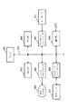
図1を参照すると、本発明の一実施の形態にかかるペン型ポインティングデバイス(以下、入力ペンとも称す)1は、色選択スイッチ2、色選択器3、発色器4、通信器5、電源6および電源スイッチ7を主要な構成要素として有しており、ペン入力形式の情報端末装置8と組み合わせて使用される。 Referring to FIG. 1, a pen-type pointing device (hereinafter also referred to as an input pen) 1 according to an embodiment of the present invention includes a color selection switch 2, a color selector 3, a color generator 4, a communication device 5, and a power source 6. The power switch 7 is a main component and is used in combination with a pen input type information terminal device 8.

電源6は、一次電池または二次電池で構成される。電源スイッチ7は、利用者が手動でオン、オフできるスイッチである。電源スイッチ7をオンにすると、電源6から電源線9を通じて、色選択器3、発色器4および通信器5に動作電力が供給され、各部が動作可能な状態となる。   The power source 6 is composed of a primary battery or a secondary battery. The power switch 7 is a switch that can be manually turned on and off by the user. When the power switch 7 is turned on, operating power is supplied from the power source 6 to the color selector 3, the color generator 4 and the communication device 5 through the power line 9, so that each unit can be operated.

色選択スイッチ2は、情報端末装置8に対してペン入力するイメージの表示色を事前に選択するための手動スイッチであり、少なくとも1つのスイッチから構成される。色選択スイッチ2の出力は信号線10により色選択器3に導かれる。   The color selection switch 2 is a manual switch for selecting in advance a display color of an image to be pen-inputted to the information terminal device 8, and includes at least one switch. The output of the color selection switch 2 is guided to the color selector 3 by the signal line 10.

色選択器3は、予め複数設定された色の中から、利用者による色選択スイッチ2の操作に応じた色を選択する回路であり、発色器4とは信号線11により、通信器5とは信号線12により、それぞれ接続されている。色選択器3は、或る色を選択した場合、選択した色を情報端末装置8に通知すべきことを信号線12を通じて通信器5へ指示し、また、その色で発色すべきことを発色器4へ信号線11を通じて指示する。   The color selector 3 is a circuit for selecting a color according to the user's operation of the color selection switch 2 from a plurality of preset colors. The color generator 4 is connected to the communication device 5 by a signal line 11. Are connected to each other by a signal line 12. When a certain color is selected, the color selector 3 instructs the communication device 5 through the signal line 12 that the selected terminal color should be notified to the information terminal device 8, and also indicates that the color should be developed. Instructs the device 4 through the signal line 11.

発色器4は、色選択器3から指示された色で入力ペンの一部を光らせる部分である。入力ペンのどの部分を発色させるかは任意であり、利用者が認知できる箇所であれば良い。   The color development device 4 is a portion that illuminates a part of the input pen with the color designated by the color selector 3. Which part of the input pen is colored is arbitrary and may be any part that can be recognized by the user.

通信器5は、色選択器3から指示された色を情報端末装置8に通知する回路である。通信器5と情報端末装置8とはケーブル等で有線接続されていても良く、ワイヤレス接続されていても良い。ワイヤレス接続の場合、通信器5は色データを無線信号や赤外線信号に変換し、情報端末装置8に送信する。有線接続の場合、通信器5はケーブル等を介して色データを情報端末装置8に送信する。有線接続の場合、信号伝送用のケーブルとは別に電力供給用のケーブルを入力ペン1と情報端末装置8との間に引き、電源6の代わりに、電力供給用ケーブルを通じて情報端末装置8から供給される電力を電源線9を通じて各部に供給する構成とすることもできる。この場合、電源スイッチ7は省略して良い。   The communication device 5 is a circuit that notifies the information terminal device 8 of the color instructed from the color selector 3. The communication device 5 and the information terminal device 8 may be wired by a cable or the like, or may be wirelessly connected. In the case of wireless connection, the communication device 5 converts the color data into a radio signal or an infrared signal and transmits it to the information terminal device 8. In the case of wired connection, the communication device 5 transmits color data to the information terminal device 8 via a cable or the like. In the case of wired connection, a power supply cable is drawn between the input pen 1 and the information terminal device 8 separately from the signal transmission cable and supplied from the information terminal device 8 through the power supply cable instead of the power supply 6. It is also possible to supply the power to each unit through the power line 9. In this case, the power switch 7 may be omitted.

このように構成された本実施の形態にかかる入力ペン1を使えば、ペン側で色選択が行え、然も選択した色でペンの一部が光るため、利用者は実際にどのような色であるかを直感的に認識することができる。   If the input pen 1 according to the present embodiment configured as described above is used, color selection can be performed on the pen side, and a part of the pen shines with the selected color. Can be recognized intuitively.

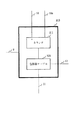
次に、情報端末装置8について説明する。情報端末装置8は、入力ペン1で指示された座標位置を検出する座標位置検出装置、カラー表示装置、および検出された座標位置にカラーイメージを表示する描画プログラムを実行する処理装置を有する。その構成の一例を図2に示す。   Next, the information terminal device 8 will be described. The information terminal device 8 includes a coordinate position detection device that detects a coordinate position indicated by the input pen 1, a color display device, and a processing device that executes a drawing program that displays a color image at the detected coordinate position. An example of the configuration is shown in FIG.

図2を参照すると、情報端末装置8の一例は、端末装置全体の制御を司るCPU801を備え、そのバス802にROM803、RAM804、LCDコントローラ805、タブレットコントローラ806、キーボードコントローラ807および通信部808が接続されている。ROM803はCPU801で実行すべき描画プログラム等の各種のプログラムを記憶する。RAM804はワークエリアとして利用される。キーボードコントローラ807は、各種のキーを有するキーボード811からのキー操作を検出してCPU801に出力する回路である。LCDコントローラ805は、カラーLCD809を制御し、CPU801から指定された表示位置に指定された色のイメージを表示する。タブレットコントローラ806は、タブレット810を制御し、タブレット810で検出された入力ペン1の接触位置に対応する座標データをCPU801に出力する。   Referring to FIG. 2, an example of the information terminal device 8 includes a CPU 801 that controls the entire terminal device, and a ROM 803, a RAM 804, an LCD controller 805, a tablet controller 806, a keyboard controller 807, and a communication unit 808 are connected to the bus 802. Has been. The ROM 803 stores various programs such as a drawing program to be executed by the CPU 801. The RAM 804 is used as a work area. The keyboard controller 807 is a circuit that detects a key operation from a keyboard 811 having various keys and outputs it to the CPU 801. The LCD controller 805 controls the color LCD 809 and displays an image of a specified color at a display position specified by the CPU 801. The tablet controller 806 controls the tablet 810 and outputs coordinate data corresponding to the contact position of the input pen 1 detected by the tablet 810 to the CPU 801.

通信部808は、入力ペン1の通信器5から通知された色データを受信し、RAM804内の色データ格納域に格納する動作を行う。通信部808は、通信器5と有線で接続されている場合、ケーブル等を介して色データを通信部5から受信し、RAM804の色データ格納域に上書きする。また、ワイヤレス接続の場合、通信器5から受信した無線信号や赤外線信号を復号して得た色データをRAM804の色データ格納域に上書きする。   The communication unit 808 receives the color data notified from the communication device 5 of the input pen 1 and performs an operation of storing it in the color data storage area in the RAM 804. When the communication unit 808 is connected to the communication device 5 by wire, the communication unit 808 receives color data from the communication unit 5 via a cable or the like, and overwrites the color data storage area of the RAM 804. In the case of wireless connection, the color data obtained by decoding the radio signal or infrared signal received from the communication device 5 is overwritten in the color data storage area of the RAM 804.

この情報端末装置8は、入力ペン1との関係において、概略以下のように動作する。入力ペン1のペン先がタブレット810に接触しその表面を移動すると、タブレット810は各接触位置に対応する座標データを順次に出力し、この座標データはタブレットコントローラ806を通じてCPU801に入力される。CPU801上で実行される描画プログラムは、各座標データからイメージの表示位置を認識し、またRAM804の色データ格納域に保持されている色データから現在の描画色を認識し、認識した表示位置に認識した色のイメージを表示すべくLCDコントローラ805に表示位置データおよび色データを順次に指定する。LCDコントローラ805は、これらの指定に従ってカラーLCD809をコントロールし、LCDの表示面における指定された位置に指定された色のイメージを表示する。   This information terminal device 8 operates in the following manner in relation to the input pen 1. When the pen tip of the input pen 1 contacts the tablet 810 and moves on the surface thereof, the tablet 810 sequentially outputs coordinate data corresponding to each contact position, and this coordinate data is input to the CPU 801 through the tablet controller 806. The drawing program executed on the CPU 801 recognizes the display position of the image from each coordinate data, recognizes the current drawing color from the color data held in the color data storage area of the RAM 804, and sets the recognized display position. In order to display the recognized color image, display position data and color data are sequentially designated on the LCD controller 805. The LCD controller 805 controls the color LCD 809 according to these specifications, and displays an image of a specified color at a specified position on the display surface of the LCD.

タブレット810は、カラーLCD809の表示面を覆うようにカラーLCD809と一体化されたものであっても良く、カラーLCD809とは分離して机上に独立して載置されるものであっても良い。また、座標位置検出装置として、本例ではタブレット810を使ったがタッチパネル等の他の種類のものであっても良い。同様に、カラー表示装置としてカラーLCDを使ったが、他の種類のものであっても良い。   The tablet 810 may be integrated with the color LCD 809 so as to cover the display surface of the color LCD 809, or may be separated from the color LCD 809 and placed independently on the desk. Further, in this example, the tablet 810 is used as the coordinate position detection device, but other types such as a touch panel may be used. Similarly, a color LCD is used as the color display device, but other types may be used.

次に本発明の実施例にかかるペン型ポインティングデバイスについて図面を参照して詳細に説明する前に、本発明の前提となるペン型ポインティングデバイスの例を幾つか図面を参照して説明する。 Before describing in detail with reference to the drawings then a pen-type pointing device according to a real施例of the present invention, an example of a pen-type pointing device which is a premise of the present invention with reference to several drawings.

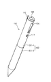
図3を参照すると、第1の前提例にかかる入力ペン101は、ペン状の筐体102の頭部に発色面103を有し、筐体102の上部付近に1つの色選択スイッチレバー104を有し、その下側に電源スイッチ7を有する。また、情報端末装置8と無線による送信を行うための送信アンテナ105が筐体102の頭部の周面に設けられている。更に筐体102は、例えばネジ込み方式で互いに分離自在な上部筐体102−1と下部筐体102−2とで構成される。   Referring to FIG. 3, the input pen 101 according to the first premise example has a coloring surface 103 on the head of the pen-shaped casing 102, and one color selection switch lever 104 is provided near the top of the casing 102. And a power switch 7 on the lower side. In addition, a transmission antenna 105 for performing wireless transmission with the information terminal device 8 is provided on the peripheral surface of the head of the housing 102. Furthermore, the housing | casing 102 is comprised by the upper housing | casing 102-1 and the lower housing | casing 102-2 which are separable mutually, for example with a screwing system.

ペン状の筐体102には、図4に示されるように、表示面が発色面103となるカラーLCD401と、そのバックライト402と、カラーLCD401と信号線404で接続されたLCDコントローラ403とが内蔵されている。これらは、発色器4を構成する。カラーLCD401は、例えば、白黒表示のLCDの内面に赤、緑、青の微細なフィルタを付けて各ドットをカラー化したものであり、LCDコントローラ403は3原色のカラードットを独立に制御する。但し、本前提例では、カラーLCD401の全表示ドットを同じ色に発色させるため、カラーLCD401に対する表示位置の指定は不要であり、どの色を発色させるかだけを指定すれば良い。色の指定は、本前提例の場合、それぞれが0か1の値をとる赤情報と緑情報と青情報との組み合わせである色情報で行う。赤情報をR、緑情報をG、青情報Bとすると、例えば赤を指定する色情報(RGB)は(100)、黒を指定する色情報(RGB)は(000)、白を指定する色情報(RGB)は(111)で表現される。   As shown in FIG. 4, the pen-shaped housing 102 includes a color LCD 401 whose display surface is the color development surface 103, a backlight 402 thereof, and an LCD controller 403 connected to the color LCD 401 and a signal line 404. Built in. These constitute the color former 4. For example, the color LCD 401 is obtained by coloring each dot by adding red, green, and blue fine filters on the inner surface of the monochrome display LCD, and the LCD controller 403 controls the three primary color dots independently. However, in this premise example, since all display dots of the color LCD 401 are colored in the same color, it is not necessary to specify the display position for the color LCD 401, and it is only necessary to specify which color is to be colored. In the case of this premise example, the color is specified by color information that is a combination of red information, green information, and blue information each having a value of 0 or 1. If red information is R, green information is G, and blue information B, for example, color information (RGB) specifying red is (100), color information (RGB) specifying black is (000), and color specifying white. Information (RGB) is expressed by (111).

また、色選択スイッチレバー104は、軸104aを中心に回動自在に軸支されると共にバネ104bによって付勢される自動復帰式のレバーとされ、このレバーによってオン、オフされるマイクロスイッチ104cが設けられている。これらは、色選択スイッチ2を構成する。   The color selection switch lever 104 is an automatic return lever that is pivotally supported about a shaft 104a and is urged by a spring 104b, and a micro switch 104c that is turned on and off by the lever. Is provided. These constitute the color selection switch 2.

更に、マイクロスイッチ104cと信号線10により、LCDコントローラ403と信号線11により接続された色選択器301と、色選択器301に信号線12により接続され、送信アンテナ105に信号線502で接続された無線通信器501と、電源スイッチ7および電源線9を通じて各部に電力を供給する電源6とが、筐体102に収納されている。電源6は、上部筐体102−1と下部筐体102−2とを分離することで取り出せ、新しいものと交換ないし充電できる。なお、送信アンテナ105、信号線502および無線通信器501で通信器5が構成される。   Further, the color selector 301 connected by the LCD controller 403 and the signal line 11 by the micro switch 104c and the signal line 10, the signal line 12 connected to the color selector 301, and the signal line 502 connected to the transmission antenna 105. The wireless communication device 501 and the power source 6 that supplies power to each unit through the power switch 7 and the power line 9 are housed in the housing 102. The power source 6 can be taken out by separating the upper housing 102-1 and the lower housing 102-2, and can be exchanged or charged with a new one. The transmission antenna 105, the signal line 502, and the wireless communication device 501 constitute the communication device 5.

図5を参照すると、色選択器301は、信号線10を通じてマイクロスイッチ104cに接続されたカウンタ302と、カウンタ302のカウント値を入力し、そのカウント値に応じた色情報を信号線11を通じてLCDコントローラ403に送出すると共に信号線12を通じて無線通信器501に送出する色情報テーブル303とから構成される。カウンタ302は、電源投入時にカウント値1に初期化され、その後、マイクロスイッチ104cが1回オン状態になる毎に、2、3、…と順に1ずつ歩進し、カウント値5の状態でマイクロスイッチ104cがオンされると、再びカウント値1に戻る巡回式カウンタとなっている。   Referring to FIG. 5, the color selector 301 inputs a counter 302 connected to the micro switch 104 c through the signal line 10 and the count value of the counter 302, and displays color information corresponding to the count value through the signal line 11 on the LCD. The color information table 303 is transmitted to the controller 403 and transmitted to the wireless communication device 501 through the signal line 12. The counter 302 is initialized to a count value of 1 when the power is turned on. Thereafter, each time the micro switch 104c is turned on once, the counter 302 is incremented by 1 in order of 2, 3,. When the switch 104c is turned on, the cyclic counter returns to the count value 1 again.

図6を参照すると、色情報テーブル303は、1から5までの各カウント値毎に色情報を保持している。なお、図6には各色情報に対応する設定色を付記してある。図6の場合、設定色は、カウント値1のとき黒、2のとき赤、3のとき緑、4のとき青、5のとき白になっており、各色情報は、赤情報、緑情報、青情報の組み合わせで指定されている。   Referring to FIG. 6, the color information table 303 holds color information for each count value from 1 to 5. In FIG. 6, set colors corresponding to each color information are added. In the case of FIG. 6, the set color is black when the count value is 1, red when 2 is, green when 3 is blue, when 4 is blue, and when 5 is white, each color information is red information, green information, It is specified as a combination of blue information.

無線通信器501は、増幅器、変調器などで構成されており、色選択器301から信号線12を通じて伝達された色情報を無線信号に変換し、送信アンテナ105より情報端末装置8に送信する。情報端末装置8側の通信部808は、この色情報を受信すると、前述したようにRAM804の色データ格納域に上書きする。描画プログラムは、色データ格納域に保持されている色情報から現在の設定色を認識する。   The wireless communication device 501 includes an amplifier, a modulator, and the like, converts the color information transmitted from the color selector 301 through the signal line 12 into a wireless signal, and transmits the wireless signal to the information terminal device 8 from the transmission antenna 105. When receiving the color information, the communication unit 808 on the information terminal device 8 side overwrites the color data storage area of the RAM 804 as described above. The drawing program recognizes the current set color from the color information held in the color data storage area.

次に、本前提例の入力ペン101の動作を説明する。利用者が電源スイッチ7をオンすると、色選択器301のカウンタ302がカウント値1に初期化され、色情報テーブル303からLCDコントローラ403および無線通信器501に色情報(RGB)=(000)が通知される。LCDコントローラ403はこの色情報に従ってカラーLCD401を制御し、その表示面、つまり入力ペン1の頭部にある発色面103の色を黒にする。一方、無線通信器501は色情報(RGB)=(000)を無線信号により情報端末装置8に送信するため、情報端末装置8側における設定色も黒となる。   Next, the operation of the input pen 101 of this premise example will be described. When the user turns on the power switch 7, the counter 302 of the color selector 301 is initialized to the count value 1, and the color information (RGB) = (000) is transferred from the color information table 303 to the LCD controller 403 and the wireless communication device 501. Be notified. The LCD controller 403 controls the color LCD 401 in accordance with the color information, and changes the color of the display surface, that is, the coloring surface 103 on the head of the input pen 1 to black. On the other hand, since the wireless communication device 501 transmits color information (RGB) = (000) to the information terminal device 8 by a wireless signal, the setting color on the information terminal device 8 side is also black.

その後、利用者が色選択スイッチレバー104を1度押し込むことでマイクロスイッチ104cをオンすると、色選択器301のカウンタ302がカウントアップしてカウント値2となり、色情報テーブル303からLCDコントローラ403および無線通信器501に色情報(RGB)=(100)が通知される。LCDコントローラ403はこの色情報に従ってカラーLCD401を制御することで、入力ペン1の頭部にある発色面103を赤に発色させる。また、無線通信器501は色情報(RGB)=(100)を無線信号により情報端末装置8に送信し、情報端末装置8側における設定色も赤となる。同様にして利用者が色選択スイッチレバー104を操作する毎に、発色面103の色が、緑、青、白、黒、赤、…と変化していき、それに応じて情報端末装置8側の設定色も変化する。   Thereafter, when the user turns on the micro switch 104c by pressing the color selection switch lever 104 once, the counter 302 of the color selector 301 counts up to a count value of 2, and the LCD controller 403 and the wireless information from the color information table 303 are counted. The communication device 501 is notified of color information (RGB) = (100). The LCD controller 403 controls the color LCD 401 in accordance with the color information, thereby causing the coloring surface 103 on the head of the input pen 1 to develop red. In addition, the wireless communication device 501 transmits color information (RGB) = (100) to the information terminal device 8 by a wireless signal, and the setting color on the information terminal device 8 side is also red. Similarly, every time the user operates the color selection switch lever 104, the color of the coloring surface 103 changes to green, blue, white, black, red,... The setting color also changes.

以上の説明では、黒、赤、緑、青、白の5種類の色を設定したが、それぞれ1、0で表現される赤情報、緑情報、青情報による色情報は合計8通りあるので、最大8種類の色を設定することが可能である。また、赤、緑、青それぞれの光る度合いを細かく調整できるカラーLCDを使用すれば、8種類より多い色を設定することが可能である。例えば光る度合いが16段階で調整可能な場合、色情報(RGB)は(000)から(161616)まで最大16×16×16種類の色を設定できる。図7に、その内、黒、赤、淡い赤、紫、青、シアン、黄、黄緑、緑、白の10種類を設定する場合の色情報テーブル303の例を示す。ここで、赤情報、緑情報、青情報に対応する数値は、値が大きいほど光る度合いが大きいことを示す。例えば、値15は光る度合いが一番大きく、値7はその約半分の度合いで光り、値0は全く光らないことを示す。   In the above description, five types of colors, black, red, green, blue, and white, are set, but there are a total of 8 color information by red information, green information, and blue information expressed by 1 and 0, respectively. Up to eight colors can be set. If a color LCD that can finely adjust the degree of red, green, and blue light is used, it is possible to set more than eight types of colors. For example, when the degree of light can be adjusted in 16 steps, the color information (RGB) can set up to 16 × 16 × 16 colors from (000) to (161616). FIG. 7 shows an example of the color information table 303 when 10 types of black, red, light red, purple, blue, cyan, yellow, yellow-green, green, and white are set. Here, the numerical values corresponding to red information, green information, and blue information indicate that the greater the value, the greater the degree of light emission. For example, a value of 15 indicates the highest degree of light, a value of 7 indicates that the light is about half that value, and a value of 0 indicates no light at all.

前述した前提例では、色選択スイッチレバー104を操作する毎に選択色を巡回的に変化させる構成のため、直前の色を選択するには一巡する必要がある。このため、選択可能な色数が増加すると所望の色を選択するのに手間取る。以下では、選択可能な色数が増加した場合であっても所望の色を迅速に選択できるようにした前提例を2つ説明する。   In the premise example described above, since the selected color is cyclically changed every time the color selection switch lever 104 is operated, it is necessary to make a round to select the immediately preceding color. For this reason, when the number of selectable colors increases, it takes time to select a desired color. In the following, two premise examples will be described in which a desired color can be quickly selected even when the number of selectable colors increases.

図8を参照すると、第2の前提例にかかる入力ペン110は、ペン状の筐体102の上部付近に色選択スイッチレバー104と色選択スイッチレバー111の2つの色選択スイッチレバーが設けられている点で第1の前提例と相違する。新たに設けた色選択スイッチレバー111は、図9に示されるように、色選択スイッチレバー104と同様に、軸111aを中心に回動自在に軸支されると共にバネ111bによって付勢される自動復帰式のレバーとされる。また、このレバーによってオン、オフされるマイクロスイッチ111cが設けられる。このマイクロスイッチ111cの出力は信号線10aを通じて色選択器310に入力される。色選択器310は、図10に示されるように、カウンタ311として可逆カウンタが使用され、マイクロスイッチ104cがオンする毎に1だけカウントアップし、マイクロスイッチ111cがオンする毎に1だけカウントダウンする。その他の構成は第1の前提例と同様である。   Referring to FIG. 8, the input pen 110 according to the second premise example is provided with two color selection switch levers, a color selection switch lever 104 and a color selection switch lever 111, near the upper part of the pen-shaped housing 102. This is different from the first premise example. As shown in FIG. 9, the newly provided color selection switch lever 111 is automatically supported by a spring 111b while being pivotally supported about a shaft 111a, similarly to the color selection switch lever 104. It is a return-type lever. Further, a micro switch 111c that is turned on and off by the lever is provided. The output of the micro switch 111c is input to the color selector 310 through the signal line 10a. As shown in FIG. 10, the color selector 310 uses a reversible counter as the counter 311 and counts up by 1 each time the microswitch 104c is turned on and counts down by 1 every time the microswitch 111c is turned on. Other configurations are the same as those of the first premise example.

本前提例によれば、一方の色選択スイッチレバー104を操作する毎に、例えば図7の色情報テーブル303を使用した構成にあっては、黒→赤→淡い赤→紫→青→シアン→黄→黄緑→緑→白→黒と変化し、他方の色選択スイッチレバー111を操作する毎に、前記とは逆方向に、黒→白→緑→黄緑→黄→シアン→青→紫→淡い赤→赤→黒と変化する。これにより、選択可能な色数が増加した場合であっても所望の色を迅速に選択できる。   According to this example, every time one of the color selection switch levers 104 is operated, for example, in the configuration using the color information table 303 of FIG. 7, black → red → light red → purple → blue → cyan → Each time the other color selection switch lever 111 is operated, black → white → green → yellow green → yellow → cyan → blue → purple changes from yellow to yellow green → green → white → black. → Pale red → Red → Black changes. Thereby, even when the number of selectable colors increases, a desired color can be selected quickly.

図11を参照すると、第3の前提例にかかる入力ペン120は、ペン状の筐体102の上部付近にツマミ121aを有するスライドスイッチ121が設けられている点で第1の前提例と相違する。スライドスイッチ121のツマミ121aは、図12に示されるように、筐体102内に設けられた可変抵抗器122のしゅう動接点122aに連結されており、可変抵抗器122には電源線9を通じて電源6の電圧が印加され、しゅう動接点122aの位置に応じた電圧が信号線10を通じて色選択器320に供給される。色選択器320は、図13に示されるように、図5のカウンタ302の代わりに、信号線10を通じて印加されるアナログ電圧をデジタル値に変換するA/D変換器321を有する。このA/D変換器321の出力値がカウント値として色情報テーブル303に出力される。その他の構成は第1の前提例と同様である。   Referring to FIG. 11, the input pen 120 according to the third premise example is different from the first premise example in that a slide switch 121 having a knob 121 a is provided in the vicinity of the top of the pen-shaped housing 102. . A knob 121 a of the slide switch 121 is connected to a sliding contact 122 a of a variable resistor 122 provided in the housing 102 as shown in FIG. 6 is applied, and a voltage corresponding to the position of the sliding contact 122 a is supplied to the color selector 320 through the signal line 10. As shown in FIG. 13, the color selector 320 includes an A / D converter 321 that converts an analog voltage applied through the signal line 10 into a digital value instead of the counter 302 of FIG. The output value of the A / D converter 321 is output to the color information table 303 as a count value. Other configurations are the same as those of the first premise example.

本前提例によれば、スライドスイッチ121のツマミ121aを一方向にスライドさせれば、例えば図7の色情報テーブル303を使用した構成にあっては、黒→赤→淡い赤→紫→青→シアン→黄→黄緑→緑→白→黒と変化し、他方向にスライドさせれば、前記とは逆方向に、黒→白→緑→黄緑→黄→シアン→青→紫→淡い赤→赤→黒と変化する。これにより、選択可能な色数が増加した場合であっても所望の色を迅速に選択できる。   According to this example, if the knob 121a of the slide switch 121 is slid in one direction, for example, in the configuration using the color information table 303 of FIG. 7, black → red → light red → purple → blue → Change from cyan → yellow → yellow-green → green → white → black, slide in the other direction, black → white → green → yellow-green → yellow → cyan → blue → purple → light red → Red → Black changes. Thereby, even when the number of selectable colors increases, a desired color can be selected quickly.

本前提例では、スライドスイッチ121を使ったが、回転スイッチを使うことも可能である。この場合、可変抵抗器122のしゅう動接点122aは回転スイッチの回転に連動するよう構成される。   In this example, the slide switch 121 is used, but a rotary switch can also be used. In this case, the sliding contact 122a of the variable resistor 122 is configured to be interlocked with the rotation of the rotary switch.

以上の各前提例では、入力ペンの頭部に発色面103を設けたが、入力ペンの他の箇所を発色させることもできる。例えば、図14に示すように、ペン状の筐体102のペン先部分を多面体に加工し、各面にカラーLCD131を張り付けることで、ペン先部分を発色面とすることができる。また、図15に示すように、色選択スイッチレバー104の片面あるいは両面にカラーLCD132を張り付けることで、色選択スイッチレバー104を発色面とすることができる。   In each of the above premise examples, the coloring surface 103 is provided on the head of the input pen, but other portions of the input pen can be colored. For example, as shown in FIG. 14, the pen tip portion of the pen-shaped housing 102 is processed into a polyhedron, and a color LCD 131 is attached to each surface, so that the pen tip portion can be a coloring surface. Further, as shown in FIG. 15, the color selection switch lever 104 can be made to be a coloring surface by attaching a color LCD 132 to one or both sides of the color selection switch lever 104.

次に本発明の実施例にかかるペン型ポインティングデバイスについて、図16を参照して説明する。 Next pen pointing device according to a real施例of the present invention will be described with reference to FIG. 16.

図16を参照すると、本発明の実施例にかかるペン型ポインティングデバイスで使用する発色器410は、発色体としての赤LED411、緑LED412、青LED413の3種類のLEDと、信号線11を通じて色選択器3から伝達される色情報中の赤情報、緑情報、青情報に応じて、赤LED411、緑LED412、青LED413の光の度合いを制御する発色制御回路414と、入力ペンの発色面に取り付けられる半透明体415と、各LED411、412、413の出射光を半透明体415に導く光学系416とから構成される。光学系416は、一端が半透明体415に接続された1本または複数本の光ファイバ417と、各LED411、412、413の出射光を光ファイバ417の他端に入射する光学レンズ418とで構成される。   Referring to FIG. 16, the color former 410 used in the pen-type pointing device according to the embodiment of the present invention includes three types of LEDs, a red LED 411, a green LED 412, and a blue LED 413 as color formers, and color selection through the signal line 11. A color control circuit 414 that controls the degree of light of the red LED 411, the green LED 412, and the blue LED 413 according to red information, green information, and blue information in the color information transmitted from the device 3, and attached to the color surface of the input pen A translucent body 415 and an optical system 416 that guides the light emitted from the LEDs 411, 412, and 413 to the translucent body 415. The optical system 416 includes one or a plurality of optical fibers 417 having one end connected to the translucent body 415, and an optical lens 418 that emits light emitted from the LEDs 411, 412, and 413 to the other end of the optical fiber 417. Composed.

発色制御回路414は、例えば前述した図6の色情報テーブル303を用いる前提例では、色情報が1のとき該当するLEDを点灯させ、色情報が0のとき該当するLEDを消灯させる。例えば、色情報(RGB)が(100)である赤の場合、赤LED411のみを点灯させる。そうすると、赤LED411から出射した赤色の光だけが光学系416を通じて半透明体415に伝搬し、半透明体415が赤く光る。また、色情報(RGB)が(111)である白の場合、全てのLEDを点灯させる。そうすると、赤、緑、青の光が光学系416および半透明体415内部で加色混合され、半透明体415が白く光る。勿論、前述した図7の色情報テーブル303を用いる前提例に対しても適用可能であり、その場合は色情報の数値に応じて該当するLEDの光の度合いを制御する。例えば、色情報(RGB)が(15、8、8)である淡い赤の場合、赤LED411の光の度合いを最大にし、緑LED412および青LED413はその約半分程度の度合いで光らせる。   For example, in the premise example using the color information table 303 of FIG. 6 described above, the color control circuit 414 turns on the corresponding LED when the color information is 1, and turns off the corresponding LED when the color information is 0. For example, when the color information (RGB) is red (100), only the red LED 411 is turned on. Then, only red light emitted from the red LED 411 propagates to the semitransparent body 415 through the optical system 416, and the semitransparent body 415 glows red. When the color information (RGB) is (111) white, all the LEDs are turned on. Then, red, green, and blue light are additively mixed in the optical system 416 and the translucent body 415, and the translucent body 415 shines white. Of course, the present invention can also be applied to the premise example using the color information table 303 of FIG. 7 described above, in which case the degree of light of the corresponding LED is controlled according to the numerical value of the color information. For example, when the color information (RGB) is light red with (15, 8, 8), the degree of light of the red LED 411 is maximized, and the green LED 412 and the blue LED 413 are made to emit about half of the light.

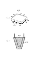
また、赤、緑、青の全てのLEDを消灯させると、半透明体415は何色でも光らないため、利用者の目には半透明体415の裏にある物体の色が半透明体415の色として認知される。従って、半透明体415の裏に黒色のフィルム等を張っておけば、黒色の表示が可能である。その場合の半透明体415の構成例を図17に示す。図17(a)は、入力ペンの頭部やスイッチ部を発色面とする場合に好適な構成を示す外観斜視図であり、平板状の半透明体415の裏面に黒フィルム419を貼付してある。また、図17(b)は、半透明体415の外形をペン先の形状に加工し、内部を空洞にして黒フィルム419を貼付した状態を示す断面図である。なお、半透明体415の裏面を黒色とするには黒フィルムを貼付する以外に、裏面を黒色でペイントするなど、任意の方法が利用できる。   Further, when all the red, green, and blue LEDs are turned off, the translucent body 415 does not shine in any number of colors. Therefore, the color of the object behind the translucent body 415 is visible to the user's eyes. It is recognized as the color. Therefore, if a black film or the like is stretched on the back of the translucent body 415, black display is possible. A configuration example of the translucent body 415 in that case is shown in FIG. FIG. 17A is an external perspective view showing a configuration suitable when the head or switch portion of the input pen is used as a coloring surface, and a black film 419 is pasted on the back surface of the flat translucent body 415. is there. FIG. 17B is a cross-sectional view showing a state in which the outer shape of the translucent body 415 is processed into the shape of a pen tip and the black film 419 is pasted with the inside being hollow. In addition, in order to make the back surface of the translucent body 415 black, arbitrary methods, such as painting the back surface in black other than sticking a black film, can be used.

本発明の一実施の形態にかかるペン型ポインティングデバイスのブロック図である。 1 is a block diagram of a pen-type pointing device according to an embodiment of the present invention. 本発明の実施の形態にかかるペン型ポインティングデバイスと組み合わせて使用される情報端末装置の構成例を示すブロック図である。An example of the configuration of an information terminal device used in combination with a pen-type pointing device in accordance with implementation of the embodiment of the present invention is a block diagram showing. 本発明の第1の前提例にかかるペン型ポインティングデバイスの外観斜視図である。1 is an external perspective view of a pen-type pointing device according to a first premise example of the present invention. 本発明の第1の前提例にかかるペン型ポインティングデバイスのブロック図である。1 is a block diagram of a pen-type pointing device according to a first premise example of the present invention. FIG. 本発明の第1の前提例にかかるペン型ポインティングデバイスで使用する色選択器の構成例を示すブロック図である。It is a block diagram which shows the structural example of the color selector used with the pen-type pointing device concerning the 1st premise example of this invention. 色情報テーブルの構成例を示す図である。It is a figure which shows the structural example of a color information table. 色情報テーブルの別の構成例を示す図である。It is a figure which shows another structural example of a color information table. 本発明の第2の前提例にかかるペン型ポインティングデバイスの外観斜視図である。It is an external appearance perspective view of the pen-type pointing device concerning the 2nd example of the present invention. 本発明の第2の前提例にかかるペン型ポインティングデバイスのブロック図である。It is a block diagram of the pen-type pointing device concerning the 2nd example of the present invention. 本発明の第2の前提例にかかるペン型ポインティングデバイスで使用する色選択器の構成例を示すブロック図である。It is a block diagram which shows the structural example of the color selector used with the pen-type pointing device concerning the 2nd example of this invention. 本発明の第3の前提例にかかるペン型ポインティングデバイスの外観斜視図である。It is an external appearance perspective view of the pen type pointing device concerning the 3rd example of the present invention. 本発明の第3の前提例にかかるペン型ポインティングデバイスのブロック図である。It is a block diagram of the pen-type pointing device concerning the 3rd example of the present invention. 本発明の第3の前提例にかかるペン型ポインティングデバイスで使用する色選択器の構成例を示すブロック図である。It is a block diagram which shows the structural example of the color selector used with the pen-type pointing device concerning the 3rd example of this invention. ペン先を発色させる前提例にかかるペン型ポインティングデバイスの要部外観斜視図である。It is a principal part external appearance perspective view of the pen-type pointing device concerning the premise example which colors a nib. スイッチを発色させる前提例にかかるペン型ポインティングデバイスの要部外観斜視図である。It is a principal part external appearance perspective view of the pen-type pointing device concerning the example of a premise which colors a switch. 本発明の実施例にかかるペン型ポインティングデバイスにおける発色器の構成例を示すブロック図である。It is a block diagram which shows the structural example of the color developing device in the pen-type pointing device concerning the Example of this invention. 半透明体の具体的な構造例を示す図である。It is a figure which shows the specific structural example of a translucent body.

符号の説明Explanation of symbols

1…ペン型ポインティングデバイス(入力ペン)
2…色選択スイッチ
3…色選択器
4…発色器
5…通信器
6…電源
7…電源スイッチ
8…情報端末装置
9…電源線
10、11、12…信号線
1 ... Pen-type pointing device (input pen)
2 ... Color selection switch 3 ... Color selector 4 ... Color generator 5 ... Communication device 6 ... Power supply 7 ... Power switch 8 ... Information terminal device 9 ... Power supply lines 10, 11, 12 ... Signal lines

Claims (6)

選択された色でペンの一部が発色するペン型ポインティングデバイスであって、指定された色の光を出射する発色体と、前記発色体の出射光が側面から入射して伝播し且つ裏面が黒色の半透明体とを備えることを特徴とするペン型ポインティングデバイス A pen-type pointing device in which a part of a pen develops a color with a selected color, a color body that emits light of a specified color, and the light emitted from the color body is incident and propagated from a side surface and the back surface is A pen-type pointing device comprising a black translucent body. 前記発色体の出射光を前記半透明体の側面に導く光学系を備えることを特徴とする請求項1記載のペン型ポインティングデバイスThe pen-type pointing device according to claim 1, further comprising an optical system that guides the emitted light of the color former to a side surface of the translucent body. 前記発色体はそれぞれ異なる単色の光を出射する複数の発光素子を含むことを特徴とする請求項1記載のペン型ポインティングデバイスThe pen-type pointing device according to claim 1, wherein the color former includes a plurality of light emitting elements that emit different colors of monochromatic light. 一端が前記半透明体の側面に接続された1本または複数本の光ファイバと、前記複数の発光素子の出射光を前記光ファイバの他端に入射する光学レンズとを含む光学系を備えることを特徴とする請求項3記載のペン型ポインティングデバイスAn optical system including one or a plurality of optical fibers, one end of which is connected to a side surface of the translucent body, and an optical lens that emits light emitted from the plurality of light emitting elements to the other end of the optical fiber; The pen-type pointing device according to claim 3. 外部から与えられる色情報に基づいて、前記複数の発光素子の光の度合いを制御する発色制御回路を備えることを特徴とする請求項3記載のペン型ポインティングデバイス4. The pen-type pointing device according to claim 3, further comprising a color development control circuit that controls a degree of light of the plurality of light emitting elements based on color information given from outside. 記半透明体の表面の少なくとも一部がデバイス外面に露出していることを特徴とする請求項1乃至5の何れか1項に記載のペン型ポインティングデバイス Pen-type pointing device according to any one of claims 1 to 5 at least part of the surface of the pre-Symbol translucent body is characterized by being exposed to the device outer surface.
JP2003413155A 2003-12-11 2003-12-11 Pen pointing device Expired - Fee Related JP3897018B2 (en)

Priority Applications (1)

Application Number Priority Date Filing Date Title
JP2003413155A JP3897018B2 (en) 2003-12-11 2003-12-11 Pen pointing device

Applications Claiming Priority (1)

Application Number Priority Date Filing Date Title
JP2003413155A JP3897018B2 (en) 2003-12-11 2003-12-11 Pen pointing device

Related Parent Applications (1)

Application Number Title Priority Date Filing Date
JP36041199A Division JP3520823B2 (en) 1999-12-20 1999-12-20 Pen pointing device

Publications (2)

Publication Number Publication Date
JP2004103042A JP2004103042A (en) 2004-04-02
JP3897018B2 true JP3897018B2 (en) 2007-03-22

Family

ID=32291201

Family Applications (1)

Application Number Title Priority Date Filing Date
JP2003413155A Expired - Fee Related JP3897018B2 (en) 2003-12-11 2003-12-11 Pen pointing device

Country Status (1)

Country Link
JP (1) JP3897018B2 (en)

Families Citing this family (1)

* Cited by examiner, † Cited by third party
Publication number Priority date Publication date Assignee Title
KR101910578B1 (en) 2012-11-09 2018-10-22 삼성전자주식회사 Color optical pen for e-board or display

Family Cites Families (9)

* Cited by examiner, † Cited by third party
Publication number Priority date Publication date Assignee Title
JPH0373926A (en) * 1989-08-15 1991-03-28 Asahi Glass Co Ltd Liquid crystal display device
JPH0423026A (en) * 1990-05-17 1992-01-27 Toshiba Corp Information display device
JPH07253844A (en) * 1994-03-16 1995-10-03 Hitachi Ltd Pen input device
JPH08115154A (en) * 1994-10-17 1996-05-07 Tamura Electric Works Ltd Pen input device
JPH0954652A (en) * 1995-08-16 1997-02-25 Sanyo Electric Co Ltd Input pen and input device using the same
JPH0990134A (en) * 1995-09-21 1997-04-04 Nitto Denko Corp Light transmission body and surface light source device using that
JPH1091316A (en) * 1996-09-17 1998-04-10 Sharp Corp Coordinate input device and program recording medium therefor
JPH10186361A (en) * 1996-12-26 1998-07-14 Sharp Corp Display device and driving method therefor
JP3520823B2 (en) * 1999-12-20 2004-04-19 日本電気株式会社 Pen pointing device

Also Published As

Publication number Publication date
JP2004103042A (en) 2004-04-02

Similar Documents

Publication Publication Date Title
US5267181A (en) Cybernetic interface for a computer that uses a hand held chord keyboard
EP1653338B1 (en) Mobile information terminal
JP2001273832A (en) Button for electronic apparatus and lighting control method for button
US8698752B2 (en) Multi-functional control interface
EP2245906B1 (en) Color selection input device and method
CN101506761A (en) Method and apparatus for matching a control with an icon
US9743481B2 (en) Independently programmable lights for use in gloves
KR101362104B1 (en) Stylus pen for controlling line color and thickness on mobile screen
JP5081166B2 (en) Control device for selecting the color of light emitted from a light source
JP3867552B2 (en) Pen-type input device, pen-type input device control program, and information input system
JP3897018B2 (en) Pen pointing device
CN202033726U (en) White board marker
JP3520823B2 (en) Pen pointing device
TWM335735U (en) Wireless mouse for controlling portable wireless radio set
RU2214619C2 (en) Keyboard, key, method for character output and change using electronic-device keyboard keys
KR102097582B1 (en) Portable and separable assistant keyboard and touchpad
CN101799718A (en) Keyboard
KR101920324B1 (en) Color Control Type Stylus Pen and Control Method Thereof
TW201312393A (en) Stylus capable of switching color and having color marking function
US7170429B2 (en) Keypad indicating arrangement including virtual key
US8035756B1 (en) Apparatus and method for television remote control with simple features
JP4094602B2 (en) Electronic device key button lighting structure
CN2901411Y (en) Human-machine interaction positioning system with flying shuttle
JP2005292490A (en) Ornamental panel and electronic apparatus
KR102579180B1 (en) An educational tool capable of recognizing voice that trains coding algorithms based on smart blocks

Legal Events

Date Code Title Description
A977 Report on retrieval

Free format text: JAPANESE INTERMEDIATE CODE: A971007

Effective date: 20060413

A131 Notification of reasons for refusal

Free format text: JAPANESE INTERMEDIATE CODE: A131

Effective date: 20060523

A131 Notification of reasons for refusal

Free format text: JAPANESE INTERMEDIATE CODE: A131

Effective date: 20060829

A521 Written amendment

Free format text: JAPANESE INTERMEDIATE CODE: A523

Effective date: 20061027

TRDD Decision of grant or rejection written
A01 Written decision to grant a patent or to grant a registration (utility model)

Free format text: JAPANESE INTERMEDIATE CODE: A01

Effective date: 20061128

A61 First payment of annual fees (during grant procedure)

Free format text: JAPANESE INTERMEDIATE CODE: A61

Effective date: 20061211

R150 Certificate of patent or registration of utility model

Free format text: JAPANESE INTERMEDIATE CODE: R150

FPAY Renewal fee payment (event date is renewal date of database)

Free format text: PAYMENT UNTIL: 20110105

Year of fee payment: 4

FPAY Renewal fee payment (event date is renewal date of database)

Free format text: PAYMENT UNTIL: 20120105

Year of fee payment: 5

FPAY Renewal fee payment (event date is renewal date of database)

Free format text: PAYMENT UNTIL: 20120105

Year of fee payment: 5

S111 Request for change of ownership or part of ownership

Free format text: JAPANESE INTERMEDIATE CODE: R313113

R371 Transfer withdrawn

Free format text: JAPANESE INTERMEDIATE CODE: R371

FPAY Renewal fee payment (event date is renewal date of database)

Free format text: PAYMENT UNTIL: 20120105

Year of fee payment: 5

S111 Request for change of ownership or part of ownership

Free format text: JAPANESE INTERMEDIATE CODE: R313113

FPAY Renewal fee payment (event date is renewal date of database)

Free format text: PAYMENT UNTIL: 20120105

Year of fee payment: 5

R350 Written notification of registration of transfer

Free format text: JAPANESE INTERMEDIATE CODE: R350

FPAY Renewal fee payment (event date is renewal date of database)

Free format text: PAYMENT UNTIL: 20130105

Year of fee payment: 6

FPAY Renewal fee payment (event date is renewal date of database)

Free format text: PAYMENT UNTIL: 20130105

Year of fee payment: 6

FPAY Renewal fee payment (event date is renewal date of database)

Free format text: PAYMENT UNTIL: 20130105

Year of fee payment: 6

FPAY Renewal fee payment (event date is renewal date of database)

Free format text: PAYMENT UNTIL: 20130105

Year of fee payment: 6

FPAY Renewal fee payment (event date is renewal date of database)

Free format text: PAYMENT UNTIL: 20140105

Year of fee payment: 7

R250 Receipt of annual fees

Free format text: JAPANESE INTERMEDIATE CODE: R250

R250 Receipt of annual fees

Free format text: JAPANESE INTERMEDIATE CODE: R250

R250 Receipt of annual fees

Free format text: JAPANESE INTERMEDIATE CODE: R250

LAPS Cancellation because of no payment of annual fees