JP3896830B2 - Droplet discharge head, driving method thereof, and droplet discharge apparatus - Google Patents
Droplet discharge head, driving method thereof, and droplet discharge apparatus Download PDFInfo
- Publication number
- JP3896830B2 JP3896830B2 JP2001369133A JP2001369133A JP3896830B2 JP 3896830 B2 JP3896830 B2 JP 3896830B2 JP 2001369133 A JP2001369133 A JP 2001369133A JP 2001369133 A JP2001369133 A JP 2001369133A JP 3896830 B2 JP3896830 B2 JP 3896830B2
- Authority
- JP
- Japan
- Prior art keywords
- voltage change
- droplet discharge
- voltage
- nozzle
- discharge head
- Prior art date
- Legal status (The legal status is an assumption and is not a legal conclusion. Google has not performed a legal analysis and makes no representation as to the accuracy of the status listed.)
- Expired - Fee Related
Links
Images


Classifications
-
- B—PERFORMING OPERATIONS; TRANSPORTING
- B41—PRINTING; LINING MACHINES; TYPEWRITERS; STAMPS
- B41J—TYPEWRITERS; SELECTIVE PRINTING MECHANISMS, i.e. MECHANISMS PRINTING OTHERWISE THAN FROM A FORME; CORRECTION OF TYPOGRAPHICAL ERRORS
- B41J2/00—Typewriters or selective printing mechanisms characterised by the printing or marking process for which they are designed
- B41J2/005—Typewriters or selective printing mechanisms characterised by the printing or marking process for which they are designed characterised by bringing liquid or particles selectively into contact with a printing material
- B41J2/01—Ink jet
- B41J2/015—Ink jet characterised by the jet generation process
- B41J2/04—Ink jet characterised by the jet generation process generating single droplets or particles on demand
- B41J2/045—Ink jet characterised by the jet generation process generating single droplets or particles on demand by pressure, e.g. electromechanical transducers
- B41J2/04501—Control methods or devices therefor, e.g. driver circuits, control circuits
- B41J2/04581—Control methods or devices therefor, e.g. driver circuits, control circuits controlling heads based on piezoelectric elements
-
- B—PERFORMING OPERATIONS; TRANSPORTING
- B41—PRINTING; LINING MACHINES; TYPEWRITERS; STAMPS
- B41J—TYPEWRITERS; SELECTIVE PRINTING MECHANISMS, i.e. MECHANISMS PRINTING OTHERWISE THAN FROM A FORME; CORRECTION OF TYPOGRAPHICAL ERRORS
- B41J2/00—Typewriters or selective printing mechanisms characterised by the printing or marking process for which they are designed
- B41J2/005—Typewriters or selective printing mechanisms characterised by the printing or marking process for which they are designed characterised by bringing liquid or particles selectively into contact with a printing material
- B41J2/01—Ink jet
- B41J2/015—Ink jet characterised by the jet generation process
- B41J2/04—Ink jet characterised by the jet generation process generating single droplets or particles on demand
- B41J2/045—Ink jet characterised by the jet generation process generating single droplets or particles on demand by pressure, e.g. electromechanical transducers
- B41J2/04501—Control methods or devices therefor, e.g. driver circuits, control circuits
- B41J2/04588—Control methods or devices therefor, e.g. driver circuits, control circuits using a specific waveform
Landscapes
- Particle Formation And Scattering Control In Inkjet Printers (AREA)
Description
【0001】
【発明の属する技術分野】
本発明は液滴吐出ヘッドおよびその駆動方法並びに液滴吐出装置に関し、特にノズルから微小な液滴を吐出して記録媒体上に文字や画像などを記録したり、基板上に微細パターンや薄膜の形成等を行うための液滴吐出ヘッドおよびその駆動方法並びに液滴吐出装置に関する。
【0002】
【従来の技術】
圧電アクチュエータ等の電気機械変換器を用いて、液体が充填された圧力発生室内に圧力波(音響波)を発生させ、その圧力波によって圧力発生室に連結されたノズルから液滴を吐出する液滴吐出方法は一般によく知られている。特に、インクの滴を吐出して記録用紙上に文字や画像などの記録を行うインクジェット記録装置は広く普及している(例えば特公昭53−12138号公報や特開平10−193587号公報など)。
【0003】
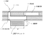
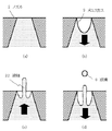
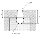
図6は、上記公報などで公知のインクジェット記録装置における液滴吐出機構(イジェクタ)の一例を示す図である。圧力発生室1には、インクを吐出するためのノズル2と、共通流路4を介してインクタンク(図示せず)からインクを導くためのインク供給路5が連結されている。また、圧力発生室1の底面には振動板6が設けられている。液滴吐出時には、圧力発生室1の外部に設けられた圧電アクチュエータ7によってこの振動板6を変位させ、圧力発生室1に体積変化を生じさせることにより、圧力発生室内に圧力波を発生させる。この圧力波によって、圧力発生室1内に充填されていたインクの一部がノズル22を通って外部に噴射され、液滴8となって飛翔する。飛翔した液滴8は記録紙等の記録媒体上に着弾し、記録ドットを形成する。こうした記録ドットの形成を、画像データに基づいて繰り返し行うことによって、記録媒体上に文字や画像が記録される。
【0004】
また、近年では、上記のような液滴吐出装置を工業的に活用することが試みられている。主な活用例としては、(a)導電性ポリマー溶液を基板上に吐出させて配線パターンやトランジスタを形成、(b)有機EL溶液を基板上に吐出させてELディスプレイパネルを形成、(c)溶融状態のハンダを基板上に吐出して電気実装用のバンプを形成、(d)UV硬化樹脂等の液滴を基板上で積層および硬化させることにより3次元物体を造形、(e)有機材料の溶液(レジスト溶液など)を基板上に吐出させて有機薄膜を形成、などが挙げられる。このように、液滴吐出装置は画像記録用としてだけではなく、広い領域で活用されつつあり、今後更にその活用範囲が広がっていくと予想される。
【0005】
こうした液滴吐出装置において、現在、大きな技術課題となっているのが「液滴体積の減少」である。すなわち、液滴吐出装置を写真画像等の印刷に用いる場合、粒状感の少ない高い画像品質を得るためには、記録紙上に形成する記録ドット(画素)をできるだけ小さくすることが重要であり、そのためには非常に微小な液滴を吐出させる必要がある。また、液滴吐出装置を工業的用途に用いる場合にも、高密度な配線パターンや高解像度ELディスプレイパネルを実現するためには、極めて微小な液滴を基板上に吐出させる必要がある。必要となる微小滴体積は、液滴吐出装置の利用方法によって大きく異なる。例えば、画像記録(印刷)を行う場合には、1〜2pl(ピコリットル)の微小滴を吐出できればほぼ十分であるが、高密度な配線パターンやトランジスタを形成するには、0.1pl以下の微小滴を吐出させる必要がある。このように、液滴吐出装置の活用範囲が拡大されるに伴って、「滴体積の減少」がこれまで以上に重要な技術課題となってきている。
【0006】
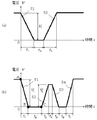
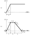
液滴吐出ヘッドで微小滴の吐出を実行するための駆動方法としては、吐出直前に圧力発生室を一旦膨張させ、ノズル開口部のメニスカスを圧力発生室側に引き込んだ状態から液滴の吐出を行う駆動方法が知られている(例えば特開昭55−17589号公報)。この種の駆動方法で用いられる駆動波形の一例を図7(a)に示す。なお、駆動電圧と圧電アクチュエータ動作との関係は、アクチュエータの構造や分極方向によって異なるが、本明細書においては、駆動電圧を増加させると圧力発生室の体積が減少し、逆に駆動電圧を減少させると圧力発生室の体積が増加するものとする。
【0007】
図7(a)の駆動波形は、圧力発生室を膨張させるための第1電圧変化プロセス51と、次いで圧力発生室を圧縮し、液滴の吐出を行うための第2電圧変化プロセス52によって構成されている。
【0008】
図8は、図7(a)の駆動波形を印加した際におけるノズル開口部のメニスカスの動きを模式的に表わした図である。初期状態においてメニスカス9は平坦な形状をしているが(図8(a))、吐出直前に圧力発生室を膨張させることにより、メニスカス9は図8(b)に示すような形状となる。すなわち、メニスカス9の中央部が圧力発生室側に大きく引き込まれ、凹型のメニスカス9が形成される。こうして凹型のメニスカス9を形成した状態から、第2電圧変化プロセス52によって圧力発生室の圧縮を行うと、図8(c)に示すように、メニスカス9の中央部に細い液柱22が形成され、次いで、液柱22の先端部が分離して液滴8が形成される(図8(d))。このときの液滴径は、形成された液柱22の太さとほぼ等しく、ノズル2の開口径よりも小さい。すなわち、こうした駆動方法を用いることにより、ノズル開口径よりも小さな液滴8を吐出することが可能となる。なお、上記のように、吐出直前のメニスカス形状を制御して微小滴吐出を行う駆動方法のことを、本明細書では以下、「メニスカス制御方式」と呼ぶ。
【0009】
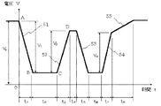
また、本発明者は、より小さな液滴を安定吐出できる駆動方法として、図7(b)に示すような駆動波形を特願平10−318443号において開示した。この駆動波形は、吐出直前にメニスカスを引き込むための第1電圧変化プロセス51、圧力発生室を圧縮して液柱を形成するための第2電圧変化プロセス52、液柱先端部から滴を早期に分離させるための第3電圧変化プロセス53、および液滴吐出後に残存する圧力波の残響を抑制するための電圧変化プロセス54によって構成されている。すなわち、図7(b)の駆動波形は、液滴の早期分離および残響抑制を目的とした電圧変化を含んでいる。これにより、図7(a)の駆動波形を用いた場合よりも滴体積の小さな液滴(4pl程度)を安定に吐出させることが可能となった。
【0010】
また、本発明者らは、さらに小さな微小液滴を吐出できる方法として、圧電アクチュエータの固有振動を利用する駆動方法を特願平11−20613号において開示した。本駆動波形では、第2電圧変化プロセス52の電圧変化時間t3および第3電圧変化プロセス53の電圧変化時間t5を、圧電アクチュエータ自体の固有周期Taと同等もしくはそれ以下に設定している点に特徴がある。これにより、圧電アクチュエータ自体の固有振動が励起され、メニスカスに周波数の高い振動を発生させることができるため、これを上記メニスカス制御方式と組み合わせることにより、通常のメニスカス制御方式よりも小さな滴を吐出することが可能となる。
【0011】
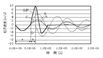
また、本発明者らは、メニスカス制御方式による吐出メカニズムの検討結果をもとに、微小滴吐出に有利となる駆動波形を特願平11−237791号および特願2000−146992号にて開示した。これらの駆動波形では、第1電圧変化プロセス51の電圧変化時間t1および第1電圧変化プロセス51の終了時刻と第2電圧変化プロセス52の開始時刻との時間差t2を特定の条件を満足するように設定している。これにより、駆動波形の節A、節B、および節C(図7(b)参照)で発生する粒子速度の位相をほぼ一致させ、第2電圧プロセス52印加時における粒子速度を急激に増加させることができる。後述するように、第2電圧プロセス52印加時に大きな粒子速度変化が生じると、ノズル中央部でメニスカスの激しい干渉が発生し、細い液柱が形成され、その結果、非常に微小な液滴を高速で吐出することが可能となる。
【0012】
【発明が解決しようとする課題】
しかしながら、上記のような従来の駆動波形で実際に吐出できる微小滴の滴体積は1〜2pl程度が下限であり、特に液滴吐出装置の工業用途で要求されるような1pl以下の微小液滴を吐出することは不可能である。
【0013】
また、従来の液滴吐出装置における別の問題点として、微小滴吐出の吐出安定性が低いという問題がある。すなわち、図7(b)に示したような駆動波形を用いることにより、1〜2pl程度の微小滴吐出は可能であるが、これを複数のイジェクタから均一に実行することは極めて困難である。微小滴の吐出状態がイジェクタ間でばらつく原因として、従来の微小滴吐出現象がノズル形状や圧力波に対して非常に敏感であることが挙げられる。すなわち、ヘッド内に複数のイジェクタが配されている場合、各イジェクタ間では、ノズルの開口径や断面形状、発生する圧力波の固有周期などに僅かながらもばらつきが存在する。従来の微小滴吐出方法では、そうしたばらつきに非常に敏感であるため、各イジェクタ間で微小滴の吐出状態が変化し、均一な微小滴吐出を実行することが困難である。
【0014】
本発明は、上記の問題点を解決すべくなされたものであり、その目的は、滴体積1pl以下の超微小液滴の吐出を実現できる液滴吐出ヘッドおよびその駆動方法並びに液滴吐出装置を提供することである。
【0015】
また、本発明の第二の目的は、微小液滴吐出の吐出安定性および均一性に優れた液滴吐出ヘッドおよびその駆動方法並びに液滴吐出装置を提供することである。
【0016】
【課題を解決するための手段】
上記課題を解決するために、本発明に係わる液滴吐出ヘッドの駆動方法は、所定のテーパー角を有する略ストレート形状のストレート部を有するノズルと、該ノズルと連通する圧力発生室と、電気機械変換器とを少なくとも有し、前記電気機械変換器に駆動電圧を印加し、前記電気機械変換器を変形させて、液体が充填された前記圧力発生室内に圧力変化を生じさせて、前記ノズルのメニスカスの中央部に形成された液柱から液滴を分離させることにより、前記ノズルから前記液滴を吐出させる液滴吐出ヘッドの駆動方法であって、前記駆動電圧の電圧波形が、前記圧力発生室の体積を膨張させて前記ノズルのメニスカスを前記圧力発生室側に引き込むための第1電圧変化プロセスと、次いで前記圧力発生室の体積を収縮させて液滴を吐出させるための第2電圧変化プロセスとを少なくとも含み構成されており、前記ストレート部の長さをlnとしたとき、前記第2電圧変化プロセスを印加する時点におけるノズル開口から前記メニスカスの先端位置までの長さを示す引き込み量Dが、0.8 ln≦D≦1.5 lnの条件を満足するように前記第1電圧変化プロセスの電圧変化量および電圧変化時間を設定することを特徴とする。
【0017】
これにより、液柱形成過程において、凹形状のメニスカスをノズル中央部で激しく干渉させることができ、滴体積の極めて小さな微小液滴を吐出することが可能となる。
【0018】
ここで、本発明の作用を図9および図10を参照しながら説明する。
【0019】
前述したように、メニスカス制御方式によって微小滴吐出を行う場合には、第1電圧変化プロセスによってメニスカスを圧力発生室側に引き込み、凹形状のメニスカスを形成する(この動作を以下「引き」と呼ぶ)。次いで、第2電圧変化プロセスによってメニスカスをノズル外側に向かって押し出すことにより(この動作を以下「押し」と呼ぶ)、ノズル中央部に細い液柱を形成させる。メニスカス制御方式で吐出される液滴の滴径は、形成される液柱の太さとほぼ一致する。また、液滴の飛翔速度(滴速)は液柱の成長速度とほぼ一致する。従って、微小な液滴を高速で飛翔させるためには、細い液柱を高速に成長させることが重要となる。
【0020】
この液柱の形成メカニズムについては、以前に本発明者らが吐出観察実験および流体解析によって調査を行い、ノズル中央部で液面を激しく干渉させることが、細い液柱を形成するための必要条件であることを見出した。特願平11−237791号および特願2000−146992号にて開示した駆動波形は、その知見に基づいたもので、駆動波形の節A、節B、および節C(図7(b)参照)で発生する粒子速度の位相をほぼ一致させることにより、第2電圧プロセス印加時における粒子速度を急激に増加させ、ノズル中央部でメニスカスの激しい干渉を発生させている。
【0021】
しかしながら、本発明者がさらに詳しく検討を行った結果、上記駆動波形は微小滴吐出に確かに有効であるが、ノズル形状やメニスカスの引き込み量によっては、必ずしも十分な微小滴吐出を実現できないことが判明した。これは、第2電圧変化プロセス印加時におけるメニスカスの動きに対する理解が不十分であったためであると言える。すなわち、特願平11−237791号および特願2000−146992号では、凹形状のメニスカスに対して「押し」を加えると、図9に示すように、メニスカスの各部は液面の法線方向に移動し、その結果、ノズル中央部に多量のインクが集中し、この局所的な体積増加によってノズル中央部に液柱が形成されると考えている。しかし、本発明者が流体解析および実測評価によって詳しく調査した結果、凹形状のメニスカスに対して「押し」を加えた場合、メニスカスの各部は必ずしも液面の法線方向に移動するわけではなく、メニスカスの動きはノズル形状に大きく依存することが明らかになった。
【0022】
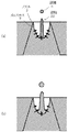
図10は、ノズル形状によるメニスカス動作の変化を模式的に示した図である。ここでは、メニスカスの移動速度を、ノズル中心軸に対して平行な方向の成分(Y成分)と、ノズル中央(中心軸)に向かう方向の成分(R成分)の二つの成分に分けて考える。微小滴吐出を実現するためには、R成分の大きな速度ベクトルをメニスカスに生じさせ、ノズル中央部で激しい液面干渉を発生させることが必要となる。
【0023】
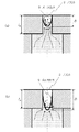
流体解析および実測評価の結果、図10(a)に示すように、引き込まれたメニスカスがノズルのストレート部内に留まっている場合(D≪ln)には、「押し」を加えられたメニスカスは、Y成分が大きな速度ベクトルをもつことが明らかになった。つまり、D≪lnの条件では、R成分の大きな速度ベクトルが得られないため、ノズル中央部での液面干渉を効率的に発生させることができず、微小滴吐出に不利となることが明らかになった。
【0024】
一方、図10(b)に示すように、メニスカスの引き込み量Dとノズルストレート部の長さlnをほぼ同等に設定した場合には、「押し」を加えた際に、R成分が支配的な速度ベクトルがメニスカスに発生することが明らかになった。これは、ノズルストレート部の下端近傍では、R成分の大きな流速分布が発生するためであると考えられる。つまり、D≒lnと設定することにより、メニスカス先端部においてR成分の大きな速度ベクトルを発生させることができる。これにより、ノズル中央部において激しい液面干渉を発生でき、極めて細い液柱を形成することが可能となる。
【0025】
以上のように、微小滴吐出に不可欠となる激しい液面干渉(極細液柱)を発生させるためには、特願平11−237791号および特願2000−146992号で述べられているように、液面速度を増加させるだけでなく、メニスカス先端部近傍における速度ベクトルのR成分が増加するように、メニスカス引き込み量Dとノズルストレート部長さlnの関係を設定することが重要である。本発明の液滴吐出ヘッドの駆動方法では、ノズル中央部において激しい液面干渉を発生させられるように、メニスカスの引き込み量Dを0.8 ln≦D≦1.5 lnの条件を満足するようになるように設定している点に大きな特徴がある。
【0026】
また、本発明の好ましい液滴吐出ヘッドの駆動方法は、前記圧力発生室内に発生する圧力波の固有周期をTcとしたとき、前記第2電圧変化プロセスの電圧変化時間を前記固有周期Tcの1/3以下に設定する。これにより、第2電圧変化プロセス印加時に大きな粒子速度が得られると共に、液柱からの液滴分離を早期に実行することができるため、滴体積の小さな微小滴を吐出できるという効果が得られる。
【0027】
また、本発明の好ましい液滴吐出ヘッドの駆動方法は、前記駆動電圧の電圧波形が、前記第2電圧変化プロセスの直後に、前記圧力発生室の体積を膨張させるための第3電圧変化プロセスを含み構成される。これにより、液柱からの液滴分離をさらに早期に実行することができるため、滴体積のさらに小さな微小滴を吐出できるという効果が得られる。なお、上記効果を有効に得るためには、前記第3電圧変化プロセスの電圧変化時間は、前記固有周期Tcの1/3以下に設定することが好ましい。また、前記第2電圧変化プロセスの終了時刻と、前記第3電圧変化プロセスの開始時刻との時間間隔は、前記固有周期Tcの1/5以下に設定することが好ましい。
【0028】
また、本発明の好ましい液滴吐出ヘッドの駆動方法は、前記駆動電圧の電圧波形が、前記第3電圧変化プロセスの直後に、前記圧力発生室の体積を収縮させるための第4電圧変化プロセスを含み構成される。これにより、微小滴吐出後の圧力波残響を抑制することができ、微小滴を連続吐出した際の安定性を向上できるという効果が得られる。なお、上記効果を有効に得るためには、前記第4電圧変化プロセスの電圧変化時間を、前記固有周期Tcの1/2以下に設定することが好ましい。
【0029】
また、本発明の好ましい液滴吐出ヘッドの駆動方法は、前記第1電圧変化プロセスの電圧変化時間を、前記電気機械変換器の固有振動の固有周期Taよりも大きく、前記固有周期Tcよりも小さく設定する。これにより、メニスカスの引き込み時に良好なメニスカス形状を得ることができ、微小滴吐出を安定化できるという効果が得られる。
【0030】
また、本発明の好ましい液滴吐出ヘッドの駆動方法は、前記第1電圧変化プロセスの電圧変化時間を、前記圧力発生室内における圧力波固有周期Tcの略1/2とし、かつ、前記第2電圧変化プロセスの開始時刻を前記第1電圧変化プロセスの終了直後に設定する。これにより、第2電圧変化プロセス印加時に、メニスカスに大きな粒子速度を発生させることができるため、ノズル中央部での液面干渉を強化でき、滴体積のさらに小さな微小滴を吐出することが可能になるという効果が得られる。なお、上記効果を有効に得るためには、前記第1電圧変化プロセスの終了時刻と、前記第2電圧変化プロセスの開始時刻との時間間隔を、前記固有周期Tcの1/5以下に設定することが好ましい。
【0031】
また、本発明の好ましい液滴吐出ヘッドの駆動方法は、前記第1電圧変化プロセスの電圧変化時間t1と、前記第1電圧変化プロセスの終了時刻と前記第2電圧変化プロセスの開始時刻の時間間隔t2を、

【0032】
また、本発明の好ましい液滴吐出ヘッドの駆動方法は、前記第2電圧変化プロセスの電圧変化時間を、前記電気機械変換器の固有振動の固有周期Taと同等もしくはそれ以下に設定する。これにより、第2電圧変化プロセス印加時に極めて大きな粒子加速度が得られると共に、液柱から液滴を極めて早期に分離することができ、滴体積の非常に小さな微小滴を吐出できるという効果が得られる。なお、上記効果を有効に得るためには、前記第3電圧変化プロセスの電圧変化時間を、前記電気機械変換器の固有振動の固有周期Taと同等もしくはそれ以下に設定し、かつ、前記第2電圧変化プロセスの開始時刻と前記第3電圧変化プロセスの開始時刻との差t0を、Ta/2≦t0≦Taの条件が満足されるように設定することが好ましい。
また、ノズルの所定のテーパー角を、10°以下とすることが好ましい。これにより、微小滴吐出に有利な曲率半径の小さなメニスカスを得ることができる。
【0033】
また、上述の課題を解決するために、本発明に係わる液滴吐出ヘッドは、所定のテーパー角を有する略ストレート形状のストレート部を有するノズル、該ノズルと連通する圧力発生室、および電気機械変換器とを少なくとも有し、前記電気機械変換器に、前記圧力発生室の体積を膨張させて前記ノズルのメニスカスを前記圧力発生室側に引き込むための第1電圧変化プロセスと、次いで前記圧力発生室の体積を収縮させて液滴を吐出させるための第2電圧変化プロセスとを少なくとも含み構成される駆動電圧を印加し、前記圧力発生室内に圧力変化を生じさせて、前記ノズルのメニスカスの中央部に形成された液柱から液滴を分離させることにより、前記ノズルから前記液滴を吐出させる液滴吐出ヘッドであって、前記第2電圧変化プロセスを印加する時点における時におけるノズル開口から前記メニスカスの先端位置までの長さを示す引き込み量をDとしたとき、前記ストレート部の長さlnをD/1.5≦ln≦D/0.8の条件を満足するように設定することを特徴とする。これにより、液柱形成過程において、凹形状のメニスカスをノズル中央部で激しく干渉させることができ、滴体積の極めて小さな微小液滴を吐出することが可能となる。
【0034】
また、本発明の好ましい液滴吐出ヘッドは、前記ノズルが、前記ストレート部と接続されたテーパ部を有する。これにより、メニスカス引き込み時におけるノズル内部への気泡巻き込みを防止することができ、信頼性に優れた液滴吐出ヘッドを実現できるという効果が得られる。
【0035】
また、本発明の好ましい液滴吐出ヘッドは、前記ノズルの開口径をdnとしたとき、前記ストレート部の長さlnが、
0.8 dn≦ln≦2.0 dn
の条件式を満足するように設定される。これにより、最低限のメニスカス引き込みによって、微小滴吐出に有利となる曲率半径の小さなメニスカスを得ることができるという効果が得られる。
【0036】
また、本発明の好ましい液滴吐出ヘッドは、前記圧力波の固有周期Tcを15μs以下に設定する。これにより、第2電圧変化プロセス印加時に大きなメニスカス速度変化が得られ、滴体積の小さな微小滴を吐出できるという効果が得られる。
【0037】
また、本発明の好ましい液滴吐出ヘッドは、前記電気機械変換器の固有振動の固有周期Taを5μs以下に設定する。これにより、電気機械変換器の固有振動を利用した駆動方法を用いる場合において、第2電圧変化プロセス印加時に非常に大きな速度変化を生じることができ、滴体積のさらに小さな微小滴を吐出できるという効果が得られる。
【0038】
また、本発明の好ましい液滴吐出ヘッドは、前記ノズルの開口径を20μm以下に設定する。これにより、微小滴吐出に有利となる曲率半径の小さなメニスカスを得ることができるという効果が得られる。
【0039】
また、本発明の好ましい液滴吐出ヘッドは、前記電気機械変換器が、圧電振動子を含み構成される。これにより、微小滴吐出に必要な圧力波を圧力発生室内に有効に発生させることができるという効果が得られる。なお、滴体積の小さな液滴吐出を実現するためには、前記圧電振動子は縦振動モードの圧電振動子であることが好ましい。
また、本発明の好ましい液滴吐出ヘッドは、ノズルの所定のテーパー角を、10°以下とする。これにより、微小滴吐出に有利な曲率半径の小さなメニスカスを得ることができる。
【0040】
また、本発明に係る液滴吐出装置は、前記液滴吐出ヘッドを搭載してなることを特徴とする。これにより、極めて微小な液滴を媒体上に吐出させることができ、高画質の画像記録、高密度の配線パターン形成、高密度ディスプレイパネルの製造等を可能とすることができる。
また、本発明の好ましい液滴吐出装置は、ノズルの所定のテーパー角を、10°以下とする。これにより、微小滴吐出に有利な曲率半径の小さなメニスカスを得ることができる。
【0041】
【発明の実施の形態】
次に、本発明の実施の形態について図面を参照して詳細に説明する。
【0042】
[第1の実施の形態]
図1は本発明の液滴吐出ヘッドの第1の実施の形態におけるノズル部の拡大図、図2はこの第1の実施の形態の液滴吐出ヘッドの駆動波形(電気機械変換器に印加する駆動電圧の電圧波形)を示す図である。液滴吐出ヘッド全体の基本構成は、図6に示す従来の液滴吐出ヘッドと同一とした。
【0043】
この第1の実施の形態の液滴吐出ヘッドは、エッチング等によって穿孔加工された複数のステンレス板(厚さ50〜150μm)を、接着剤によって積層接合することにより作製した。ヘッドには32個の圧力発生室1(図6の紙面垂直方向に配列)が設けられており、それらは供給路5を介して共通流路4によって連結されている。共通流路4は液体タンク(図示せず)と連結されており、各圧力発生室1に液体を導く働きをしている。各圧力発生室1には、液滴8を吐出するためのノズル2が連結されている。また、圧力発生室1の底面には振動板6が形成されており、振動板6には電気機械変換器としての圧電アクチュエータ(圧電振動子)7が取り付けられている。この圧電アクチュエータ7に駆動波形(駆動電圧)を印加すると、圧電アクチュエータ7が変形し、液体が充填された圧力発生室1を膨張または圧縮させる。圧力発生室1に体積変化が生じると、圧力発生室1内に圧力波が発生する。この圧力波の作用によってノズル部の液体が運動し、ノズル2から外部へ排出されることにより液滴8が形成される。
【0044】
この第1の実施の形態において、ノズル2はポリイミドフィルムをエキシマレーザーで穿孔することにより形成した。ノズル開口径は20μm、ノズル長さは25μmであり、ノズル2の断面形状はテーパー角10°以下の略ストレート形状とした(図1参照)。すなわち、この第1の実施の形態では、ノズル2はストレート部のみから構成される。
【0045】
供給路5はステンレス板をプレスによって穿孔することにより形成し、開口径約30μm、長さ75μmのテーパー形状とした。振動板6には電鋳(エレクトロフォーミング)で成形したニッケルの薄板を用いた。圧電アクチュエータ7には積層型圧電セラミクスを用いた。
【0046】
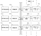
図27は、圧電アクチュエータを駆動するための駆動回路の基本構成を示す図である。駆動回路は、波形発生回路41、増幅回路42、およびスイッチング回路(トランスファ・ゲート回路)43を含み構成される。波形発生回路41は、デジタル・アナログ変換回路と積分回路とから構成され、駆動波形データをアナログ変換した後、積分処理して駆動波形信号を発生する。増幅回路42は、波形発生回路41から供給された駆動波形信号を電圧増幅および/または電流増幅して増幅駆動波形信号として出力する。スイッチング回路43a、43b、43cは、液滴吐出のオン・オフ制御を行うもので、画像パターンデータ等をもとに生成された信号に基づいて、駆動波形信号を圧電アクチュエータ7に印加する。
【0047】
なお、吐出させる液滴の径を多段階に切り替える場合、すなわち滴径変調を実行する場合には、図28に示すような駆動回路を使用する。この例の駆動回路では、滴径を3段階(大滴、中滴、小滴)に変調するために、それぞれの滴径に応じた3種類の波形発生回路41a、41b、41cを具備しており、各波形は増幅回路42a、42b、42cによって増幅される。記録時には、画像パターンデータ等をもとに、圧電アクチュエータ7に印加される駆動波形がスイッチング回路43a、43b、43cによって切り替えられ、所望滴径の液滴が吐出される。なお、圧電アクチュエータを駆動するための駆動回路は、この実施の形態に示した構成のものに限らず、他の構成のものを用いることも可能である。
【0048】
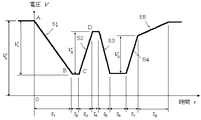
この第1の実施の形態で使用した駆動波形は、図2に示すように、吐出直前に圧力発生室1を膨張させるための第1電圧変化プロセス51、圧力発生室1を急激な速度で圧縮するための第2電圧変化プロセス52、圧力発生室1を急激な速度で膨張させるための第3電圧変化プロセス53、および圧力発生室1を再び急激な速度で圧縮するための第4電圧変化プロセス54、および印加電圧を基準電圧に戻すための第5電圧変化プロセス55によって構成されている。それぞれの電圧変化における電圧変化時間および電圧変化量は、区間t1=2μs、区間t2=2μs、区間t3=2μs、区間t4=0.5μs、区間t5=2μs、区間t6=0.3μs、区間t7=2.2μs、区間t8=6μs、電圧変化量V1=15V、電圧変化量V2=8V、電圧変化量V3=14V、バイアス電圧Vb=20Vに夫々設定した。
【0049】
この駆動波形が圧電アクチュエータに印加されると、第1電圧変化プロセス51によってノズル開口部のメニスカスが一旦圧力発生室側に引き込まれ、凹形状のメニスカスを形成する(図1、図8(b)参照)。その後、第2電圧変化プロセス52が加えられると、ノズル中央部に細い液柱が形成され、更に第3電圧変化プロセス53によって液柱が早期に分断されることにより、ノズル径よりも小さな液滴が吐出される。また、液滴吐出後に残存する圧力波の残響は、第4電圧変化プロセス54によって抑制される。
【0050】
ここで、メニスカスの粒子速度および位置を理論計算によって求めるための等価電気回路モデルについて説明する。図11(a)は、図6に示した液滴吐出ヘッドを等価電気回路に置き換えたものである。ここで、mはイナータンス[kg/m4]、rは音響抵抗[Ns/m5]、cは音響容量[m5/N]、uは体積速度[m3/s]、φは圧力[Pa]を表わし、添字の0は駆動部(圧電アクチュエータ)、添字の1は圧力発生室、添字の2は供給路、添字の3はノズルをそれぞれ意味している。
【0051】
図11(a)の回路において、圧電アクチュエータに高剛性の積層型圧電アクチュエータを使用し、かつ、駆動波形の各電圧変化プロセスが、圧電アクチュエータの固有振動の固有周期Ta(後述)よりも大きく設定されている場合には、振動系のイナータンスm0、音響抵抗r0、および音響容量c0は無視することができる。また、圧力波の解析時には、ノズルの音響容量c3も無視することができるため、図11(a)の回路は図11(c)のように簡略化できる。
【0052】
ノズルと供給路のイナータンスおよび音響抵抗に、m2=k・m3、r2=k・r3の関係が成り立つと仮定し、図12(a)のように立ち上がり角度θをもつ駆動波形を入力した場合について回路解析を行うと、0≦t≦t1の時間内におけるノズル部での粒子速度v3’は、
【0053】
図12(b)のような複雑な形状の駆動波形を用いた場合の粒子速度は、駆動波形の各節(A、B、C、D)で発生する粒子速度を重ね合わせていくことによって求めることができる。すなわち、図12(b)の駆動波形で発生する粒子速度v3は、
【0054】
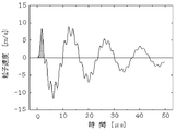
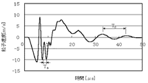
図3の実線は、図2の駆動波形を入力した際のメニスカスの粒子速度を式(2)によって求めた結果である。なお、式(2)により求めた粒子速度は、レーザードップラー計を用いて実測した結果(図3の点線)と良く一致しており、式(2)によってメニスカスの粒子速度を正確に求められることが確認された。なお、本実施の形態の液滴吐出ヘッドにおいて、圧力発生室1内に発生する圧力波の固有周期Tcは10μsであった。
【0055】
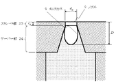
液滴吐出直前のメニスカス引き込み量(体積)は、図3の斜線部の面積とノズル開口径の積として求めることができる。メニスカスの断面形状を放物線状と近似すると、本実施の形態でのメニスカス引き込み量(先端位置)Dは約30μmと算出される。すなわち、本実施の形態では、図1に示すように、引き込まれたメニスカスの先端がノズルの下端よりも僅かに飛び出した状態となる。
【0056】
上記のように、メニスカスの引き込み量Dをノズル長さlnとほぼ同等に設定することにより、第2電圧変化プロセス52によってメニスカスに「押し」を加えた際に、メニスカス先端部近傍においてR成分の大きな速度ベクトルを発生させることができる(図10参照)。これにより、ノズル中央部において激しい液面干渉を発生でき、極めて細い液柱を形成することが可能となる。実際に本実施の形態の液滴吐出ヘッドを用いて吐出実験を行った結果、滴体積1pl、滴速8m/sの微小滴吐出を実行することができた。
【0057】
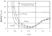
図4は、メニスカスの引き込み量Dおよびノズル長さlnを変化させて、得られる最小滴径を調べた結果である。メニスカスの引き込み量Dは、図2の駆動波形における電圧変化量V1を増減することによって変化させた。この結果から、メニスカスの引き込み量Dを0.8 ln≦D≦1.5 lnの範囲内に設定すると非常に小さな滴が得られるのに対し、D≦0.8 lnでは十分な微小滴吐出が実行困難であることがわかる。これは、D≦0.8 lnの条件では、メニスカスにR成分の大きな速度ベクトルを発生させることができないためである。また、D≧1.5 lnの範囲でも滴体積の増加が確認された。これは、メニスカスの引き込み量Dがノズル長さlnを大きく超えると、メニスカス形状が図13に示すようになり、メニスカスの曲率半径が増加するためと考えられる。従って、滴体積の小さな微小滴を安定に吐出させるためには、メニスカスの引き込み量Dを
0.8 ln≦D≦1.5 ln (3)
の範囲内に設定することが最適である。
【0058】
また、本実施の形態では、微小滴吐出の安定性および均一性が非常に高いことが確認された。具体的には、ヘッド内に設けた32個のイジェクタから微小滴を同時吐出した場合、各ノズルから吐出される微小滴の滴体積および滴速にそれぞれ約±2%以内の均一性を得ることができた。また、駆動周波数を1〜15kHzの範囲で変化させても、滴体積および滴速の変化を±3%以内に抑えられることが確認された。従来の液滴吐出ヘッドおよび駆動方法では、イジェクタ間に約±5%以上、駆動周波数によって約±8%以上の滴体積および滴速の変化が発生していたのと比較すると、本発明の液滴吐出ヘッドは、微小滴吐出の安定性および均一性に非常に優れていると言える。
【0059】
本発明の液滴吐出ヘッドおよび駆動方法で、微小滴吐出の安定性および均一性を向上できる理由は、微小滴吐出に必要となる極細液柱の形成方法に依っている。すなわち、従来の微小滴吐出方法では、駆動波形の最適化のみによって極細液柱の形成を行っていたため、イジェクタ間の固有周期Tcのばらつき等によって液柱の形成状態が変化し、結果的に滴体積や滴速に大きなばらつきを発生させていた。一方、本発明の液滴吐出ヘッドおよび駆動方法は、メニスカス引き込み量とノズル形状の最適設定によって極細液柱を形成している。メニスカス引き込み量やノズル形状は、固有周期Tcなどと比較すると、均一性を確保することが容易である。従って、本発明の液滴吐出ヘッドおよび駆動方法では、高い安定性および均一性を有する微小滴吐出が可能となる。
【0060】
なお、本実施の形態では、ノズル開口径を20μm、ノズル長さを25μmに設定したが、これは微小滴吐出に有利となる曲率半径の小さなメニスカスを形成するためである。すなわち、引き込まれたメニスカスの断面形状を放物線状と見なすと、メニスカス先端の曲率半径Rは、
R=dn 2/(8・D) (4)
によって表わされる。
【0061】
つまり、メニスカス先端の曲率半径Rを小さくするためには、ノズル径dnの減少およびメニスカス引き込み量Dの増加が有効となる。そこで、本実施の形態では、ノズル開口径を20μmと小さく設定し、さらにノズル長さln(≒メニスカス引き込み量D)を25μmと大きく設定することにより、微小滴吐出に有利となる曲率半径の小さなメニスカスを形成した。
【0062】
また、流体解析の結果、メニスカスの引き込み量Dがノズル径dnに対して一定以上大きくなると、メニスカス形状が放物線でなくなり、曲率半径もあまり減少しなくなることが明らかになった。また、吐出実験の結果、メニスカスの引き込み量を非常に大きく設定すると、特に連続吐出時における微小滴吐出の安定性が低下することも明らかになった。従って、メニスカスの引き込み量Dは必要最低限に設定することが望ましい。
【0063】
図5は、メニスカス引き込み量Dと曲率半径Rとの関係を調べた結果である。D≦2.0 dnの範囲では、DとRの間に式(4)の関係が成り立つが、D>2.0 dnの範囲では、RはDに依存しなくなることが明らかになった。また、D≦0.8 dnの範囲では、小さな曲率半径Rを得ることが困難である。従って、曲率半径の小さなメニスカスを最低限のメニスカス引き込み量で得るためには、ノズル開口径dnとノズル長さln(≒メニスカス引き込み量D)の関係を、
0.8 dn≦ln≦2.0 dn
の条件式を満足するように設定することが望ましい。
【0064】
また、微小滴吐出に有利な曲率半径の小さなメニスカスを得るためには、ノズル(またはノズルのストレート部)のテーパー角θnは小さいことが望ましく、具体的には10°以下であることが好ましい。ただし、この範囲外のテーパー角を用いても不十分ながら本発明の効果を得ることは可能である。
【0065】
なお、滴体積の小さな液滴を吐出するためには、本実施の形態のように、第2電圧変化プロセス52の電圧変化時間t3および第3電圧変化プロセス53の電圧変化時間t5を固有周期Tcの1/3以下に設定することが好ましい。また、第2電圧変化プロセス52の終了時刻と第3電圧変化プロセス53の開始時刻との時間間隔(t4)を固有周期Tcの1/5以下に設定することが好ましい。なぜならば、こうした駆動波形を用いることにより、滴吐出時に大きな粒子速度が得られると共に、液柱からの液滴分離を早期に実行することができ、滴体積の小さな微小滴を吐出することが可能となるからである。すなわち、微小滴吐出を実行するためには、図3の斜線部面積が小さくなるほど有利となるが、上記のような駆動波形を用いることにより、斜線部面積の小さな粒子速度変化を得ることが可能となる。
【0066】
また、安定した微小滴吐出を実現するためには、本実施の形態のように、第4電圧変化プロセス54によって液滴吐出後の圧力波残響を抑制することが有効となる。図3の粒子速度変化において、t>12μsでは粒子速度の振幅が非常に小さくなっているが、これは、液滴吐出後における圧力波残響が第4電圧変化プロセス54によって良好に抑制されているためである。このように圧力波残響が抑制されると、微小滴を連続吐出した場合に、直前の吐出の影響を受け難くなるため、微小滴を安定に連続吐出することが可能となる。なお、残響抑制を効果的に実行するためには、第4電圧変化プロセス54の電圧変化時間t7を、前記固有周期Tcの1/2以下に設定することが好ましい。
【0067】
[第2の実施の形態]
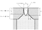
図14は本発明の液滴吐出ヘッドの第2の実施の形態におけるノズル形状を示した図である。ノズル以外の部分の構造は、第1の実施の形態と同一とした。すなわち、本実施の形態の液滴吐出ヘッドは、ノズルをストレート部23とテーパー部24の組み合わせにより構成している点に特徴がある。
【0068】
ノズルをこうした構造とすることにより、ノズル内部への気泡巻き込みの発生を有効に防止することが可能となり、吐出安定性および信頼性の高い液滴吐出ヘッドを実現することが可能となる。すなわち、本発明では、ノズルストレート部23の長さとほぼ同程度までメニスカスの引き込みを行うため、ノズル内部に気泡を巻き込みやすいという問題がある。特に、第1の実施の形態のようにノズルをストレート部のみで構成した場合には、ストレート部の下端に大きな段差が形成されるため、気泡が段差部に留まりやすく、気泡巻き込みが発生しやすい。液滴吐出ヘッドは、圧力発生室内に発生させた圧力波によって液滴を吐出させるため、流路内に気泡が存在すると正常な圧力波を発生できなくなり、吐出状態が大きく変化してしまう。特に、メニスカス制御による微小滴吐出は圧力波の特性(振幅、固有周期)に敏感であるため、気泡巻き込みが発生すると吐出が不可能になってしまう可能性が高い。
【0069】
そこで本実施の形態では、ノズル2をストレート部23とテーパー部24により構成し、ストレート部23の下端に段差が発生することを防いでいる。テーパー部24の形状は、気泡巻き込み防止するという作用と、メニスカス9にR成分の大きな速度ベクトルを発生するという作用を両立できるように設定している。本実施の形態においてノズル2は、ステンレス板をプレスによって穿孔することにより形成した。ノズル開口径dnは20μm、ストレート部23の長さlnは25μm、テーパー部24の長さは30μm、テーパー部のテーパー角θtは約45°とした。
【0070】
本実施の形態の液滴吐出ヘッドを用いて吐出実験を実施した結果(図2の駆動波形を使用)、1plの微小滴を10kHzの駆動周波数で1時間連続吐出しても、気泡巻き込みが全く発生しないことが確認された。一方、第1の実施の形態のインクジェット記録ヘッドについても同様の吐出試験を実施したところ、約1%のノズルで気泡巻き込みによる不吐出が発生した。このことから、ノズルをストレート部とテーパー部により構成した本実施の形態は、液滴吐出ヘッドの信頼性を向上させるのに有効であると言える。
【0071】
なお、ストレート部の下端に接続する部分の形状はテーパー形状であることが最適であるが、メニスカスにR成分の大きな速度ベクトルを発生でき、かつ、気泡巻き込みの抑制作用を得ることができれば、テーパー形状以外の形状を適用してもかまわない。
【0072】
また、テーパー部24のテーパー角θtは、気泡巻き込み防止するという作用と、メニスカス先端にR成分の大きな速度ベクトルを発生するという作用を両立するという観点から、30〜60°の範囲が好ましいが、この範囲外のテーパー角を用いても不十分ながら本発明の効果を得ることは可能である。
【0073】
なお、ストレート部とテーパー部の組み合わせによるノズル構成は、従来から知られているが(例えば特開平10−226070号公報)、これらの従来技術は、本発明とは全く異なるものである。すなわち、従来のノズルでは、ストレート部はノズル開口径精度の確保や液滴の吐出方向精度を向上させることを目的として設けられており、その長さは通常10〜20μm程度と小さい。また、テーパー部のテーパー角も通常20°以下と小さい。そのため、従来のノズルを用いてメニスカス制御方式による微小滴吐出を行った場合、本発明が目的としている超微小滴の吐出(ノズル中央部での激しいメニスカス干渉)を実現することは極めて困難である。なぜならば、従来ノズルを用いてメニスカス制御方式による微小滴吐出を行う場合、図15に示すように、メニスカスはテーパー部の内部まで引き込まれる必要がある(ストレート部の長さが短いため)。そのため、メニスカス先端の曲率半径は増大してしまう。また、テーパー部のテーパー角が小さいため、「押し」を加えた際にメニスカスの速度ベクトルには大きなR成分を得ることが困難である。実際、図15に示した従来ノズルを用いて微小滴吐出を行った結果、吐出できる微小滴は2plが限界であった。
【0074】
つまり、ノズルをストレート部とテーパー部により構成するだけでは本発明の効果を得ることはできず、あくまでもストレート部の長さlnとメニスカス引き込み量Dの関係を最適設定することにより始めて本発明の効果を得ることが可能となる。
【0075】
[第3の実施の形態]
図16は、本発明の液滴吐出ヘッドの第3の実施の形態における駆動波形である。本駆動波形は、吐出直前に圧力発生室を膨張させるための第1電圧変化プロセス51、圧力発生室を急激な速度で圧縮するための第2電圧変化プロセス52、圧力発生室を急激な速度で膨張させるための第3電圧変化プロセス53、および圧力発生室を再び急激な速度で圧縮するための第4電圧変化プロセス54、および印加電圧を基準電圧に戻すための第5電圧変化プロセス55によって構成されている。すなわち、本駆動波形の基本要素は第1の実施の形態と同様であるが、第1電圧変化プロセス51の電圧変化時間t1を固有周期Tc(=2π/Ec)の略1/2に設定し、かつ、第1電圧変化プロセス51の終了時刻と第2電圧変化プロセス52の開始時刻との間隔(t2)を非常に小さく設定している点に特徴がある。これは、以下に述べるように、第2電圧変化プロセス52の印加時にメニスカスに大きな粒子加速度を発生させ、滴体積のさらに小さな微小滴を吐出可能とするためである。
【0076】
図17は、図16の駆動波形に対し、式(2)を用いて粒子速度v3を求めた結果である(式(1)の振動成分のみを考慮)。図17において、細線はA、B、C、Dの各節で発生するそれぞれの粒子速度を示しており、太線はそれらを重ね合わせた粒子速度、すなわち実際にメニスカスに生じる粒子速度変化を表わしている。
【0077】
駆動波形において、t1を固有周期Tcの1/2に設定し、t2を極めて小さく設定した場合、図17に示すように、節A、節B、および節Cで発生する粒子速度変化の位相はほぼ一致する。そのため、(t1+t2)≦t≦(t1+t2+t3)の時間範囲(図17のbの時間範囲)において、粒子速度の振幅が急激に増加し、非常に急峻な速度変化が生じる。
【0078】
前述したように、液柱形成過程におけるメニスカスの速度が大きいほど、ノズル中央部で激しいメニスカス干渉が発生し、微小滴の吐出に有利な極細液柱の形成が可能となる。従って、図12(a)に示すように、節A、節B、および節Cで発生する粒子速度変化の位相はほぼ一致させ、(t1+t2)≦t≦(t1+t2+t3)の時間範囲で大きな粒子加速度を発生させることは、微小滴吐出に極めて有利となる。
【0079】
本実施の形態で用いた液滴吐出ヘッドの固有周期Tcは10μsであるため、第1電圧変化プロセス51の電圧変化時間t1は5μsに設定し、t2は0.5μsに設定した。なお、上述した粒子速度の位相一致の効果を得るためには、t2は固有周期Tcの1/5以下に設定することが望ましい。
【0080】
また、メニスカスの引き込み量Dが0.8 ln≦D≦1.5 lnの条件を満足するように、電圧変化量V1は25Vに設定した。また、区間t3=2μs、区間t4=0.5μs、区間t5=2μs、区間t6=0.3μs、区間t7=2.2μs、区間t8=17μs、電圧変化量V2=8V、電圧変化量V3=13V、バイアス電圧Vb=20Vに夫々設定した。
【0081】
本実施の形態の液滴吐出ヘッドを用いて吐出実験を行った結果、滴体積0.5pl、滴速8.2m/sの微小滴吐出を実行することができた。このように、メニスカス引き込み量Dをノズル長さlnに対して最適設定すると同時に、駆動波形の節A、節B、および節Cで発生する粒子速度変化の位相を一致させ、「押し」の際のメニスカスの粒子加速度を増加することにより、第1の実施の形態よりもさらに小さな微小滴吐出が可能になることが確認された。すなわち、本実施の形態は、メニスカス引き込み量Dの最適化と、「押し」の際の粒子速度増加という、微小滴吐出に有効な二つの手段を組み合わせたものである。
【0082】
[第4の実施の形態]
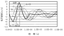
図18は、本発明の液滴吐出ヘッドの第4の実施の形態における駆動波形である。本駆動波形は、吐出直前に圧力発生室を膨張させるための第1電圧変化プロセス51、圧力発生室を急激な速度で圧縮するための第2電圧変化プロセス52、圧力発生室を急激な速度で膨張させるための第3電圧変化プロセス53、圧力発生室を再び急激な速度で圧縮するための第4電圧変化プロセス54、および印加電圧を基準電圧に戻すための第5電圧変化プロセス55によって構成されている。すなわち、本駆動波形の基本要素も第1の実施の形態および第2の実施の形態と同様であるが、第1電圧変化プロセス51の電圧変化時間t1と、第1電圧変化プロセス51の終了時刻と第2電圧変化プロセス52の開始時刻との時間間隔(t2)を一定の条件を満足するように設定している点に特徴がある。これは、以下に述べるように、第2電圧変化プロセス52の印加時にメニスカスに大きな粒子加速度を発生させ、滴体積のさらに小さな微小滴を吐出可能とするためである。
【0083】
図19は、図18の駆動波形に対し、式(2)を用いて粒子速度v3を求めた結果である(式(1)の振動成分のみを考慮)。図19において、細線はA、B、C、Dの各節で発生するそれぞれの粒子速度を示しており、太線はそれらを重ね合わせた粒子速度、すなわち実際にメニスカスに生じる粒子速度変化を表わしている。
【0084】
式(1)から、節A、B、Cで発生する粒子速度vA、vB、vCの振動成分は、それぞれ
【0085】
正弦波の重ね合わせにより、t1<t<(t1+t2)での粒子速度は
【0086】
図20は、式(5)をもとに、粒子速度振幅を最大とするt2の値をプロットした結果である(Tc=10μsとして計算)。t1の設定値に応じて、最適なt2が存在することがわかる。
【0087】
上記のように、式(5)に従ってt1、t2を設定した場合、図19に示すように、(t1+t2)≦t≦(t1+t2+t3)の時間範囲(図19のbの時間範囲)では、粒子速度の振幅が急激に増加し、非常に急峻な速度変化が生じる。これにより、ノズル中央部で激しいメニスカス干渉を生じさせることができ、微小滴の吐出に有利となる。
【0088】
本実施の形態では、式(5)の条件を満足するように、t1=2μs、t2=1.5μsに設定した。また、メニスカスの引き込み量Dが0.8 ln≦D≦1.5 lnの条件を満足するように、V1=15Vに設定した。区間t3=2μs、区間t4=0.5μs、区間t5=2μs、区間t6=0.3μs、区間t7=2.3μs、区間t8=8μs、電圧変化量V2=10V、電圧変化量V3=13V、バイアス電圧Vb=20Vに夫々設定した。
【0089】
本実施の形態の液滴吐出ヘッドを用いて吐出実験を行った結果、滴体積0.6pl、滴速8.0m/sの微小滴吐出を実行することができた。
【0090】
[第5の実施の形態]
図21は、本発明の液滴吐出ヘッドの第5の実施の形態における駆動波形である。本駆動波形は、吐出直前に圧力発生室を膨張させるための第1電圧変化プロセス51、圧力発生室を急激な速度で圧縮するための第2電圧変化プロセス52、圧力発生室を急激な速度で膨張させるための第3電圧変化プロセス53、圧力発生室を再び急激な速度で圧縮するための第4電圧変化プロセス54、および印加電圧を基準電圧に戻すための第5電圧変化プロセス55によって構成されている。すなわち、本駆動波形の基本要素も第1〜第3の実施の形態と同様であるが、第2電圧変化プロセス52の電圧変化時間t3と、第3電圧変化プロセス53の電圧変化時間t5を圧電アクチュエータ自体の固有周期Taよりも小さく設定している点に特徴がある。これは、以下に述べるように、第2電圧変化プロセス52の印加時にメニスカスに大きな粒子加速度を発生させ、滴体積のさらに小さな微小滴を吐出可能とするためである。
【0091】
ここで、本実施の形態の駆動波形が滴体積の小さな微小滴を吐出するのに有利である理由を、等価電気回路モデルを用いて説明する。液滴吐出ヘッドの等価電気回路は、前述したように、図11(a)によって表わされる。圧電アクチュエータに、高剛性の圧電アクチュエータ(縦振動モードの積層圧電アクチュエータなど)を使用した場合には、図11(a)の回路には、前述した図11(c)の振動系と共に、図11(b)に示される振動系が含まれる。図11(b)は、圧電アクチュエータ自体の固有振動を示しており、固有周期Taは
【0092】
本実施の形態の液滴吐出ヘッドでは、圧電アクチュエータの長さLは1.1mm、密度ρpは8.0×10³kg/m3、弾性係数Epは68GPaであるため、圧電アクチュエータ自体の固有周期Taは1.6μsである。
【0093】
この圧電アクチュエータ自体の固有振動は、特定の駆動波形を印加することにより励起することができる。図23は、図11(a)の回路で、圧力φ(駆動電圧に比例)を図22(a)に示すように変化させた場合におけるノズル部粒子速度v3の変化を求めた結果である。圧力φの立ち上げ時間t1を固有周期Taよりも大きく設定した場合には、図23(a)に示すように、粒子速度v3は固有周期Tcで振動する。すなわち、この場合、粒子速度v3は図11(c)の回路のみによって支配される。これが、従来の液滴吐出ヘッドにおける圧力発生形態である。一方、圧力φの立ち上げ時間t1を固有周期Taと同等もしくはそれ以下に設定した場合、粒子速度v3の変化は図23(b)に示すようになる。この場合、図11(b)の振動系が励起され、その結果、粒子速度v3の変化は固有周期Tcの振動と固有周期Taの振動が重畳したものとなる。つまり、圧力φの立ち上げ時間を固有周期Taと同等もしくはそれ以下に設定することにより、圧電アクチュエータ自体の固有周期でメニスカスを振動させることが可能となる。
【0094】
次に、圧力φの変化を、図22(b)に示すような台形波形状とした場合について考える。ここで、立ち上げ時間t1および立ち下げ時間t3は、どちらも固有周期Taと同等もしくはそれ以下に設定されており、また、立ち上げの開始時刻と立ち下げの開始時刻との時間差(t0)を、Ta/2≦t0≦Taに設定すると、メニスカスの粒子速度v3は図24に示すように変化する。すなわち、立ち上げ部57によって急激に伸長された圧電アクチュエータが、圧電アクチュエータの固有振動で縮もうとするタイミングに合わせて圧電アクチュエータを収縮させる電圧変化58が印加されるため、圧電アクチュエータは急激に収縮し、その結果、粒子速度v3は非常に早いタイミングでv3=0に戻ることになる。
【0095】
上記の作用を利用し、第2電圧変化プロセス52の電圧変化時間t3を固有周期Taと同等もしくはそれ以下に設定することにより、「押し」の過程におけるメニスカス速度に大きな変化を生じさせることができる。また、第3電圧変化プロセス53の電圧変化時間t5を固有周期Taと同等もしくはそれ以下に設定し、かつ、第2電圧変化プロセス52の開始時刻と第3電圧変化プロセス53の開始時刻との差t0をTa/2≦t0≦Taの範囲内に設定することにより、極めて早いタイミングで液柱から液滴を分離させることができ、滴体積の極めて小さな液滴を吐出することが可能となる。図21の駆動波形は、そうした作用が得られるように、t3を0.5μs、t4を1μs、t5を0.5μsに設定している。すなわち、第1〜第4の実施の形態では、図11(c)の回路のみを利用して液滴吐出を行っていたのに対し、本実施の形態では、駆動部(圧電アクチュエータ)自体の固有振動も利用して液滴吐出を行う点が大きな特徴である。
【0096】
また、第1電圧変化プロセス51の立ち下げ時間t1は、駆動波形の節A、節B、および節Cで発生する粒子速度変化の位相を一致させるために、固有周期Tcの1/2(5μs)に設定し、第1電圧変化プロセス51と第2電圧変化プロセス52との時間間隔(t2)は0.2μsと小さく設定した。また、メニスカスの引き込み量Dが0.8 ln≦D≦1.5 lnの条件を満足するように、電圧変化量V1は20Vに設定した。この駆動波形を印加した際のメニスカスの動きをレーザードップラー計によって観察した結果を図25に示す。
【0097】
実際に、図21の駆動波形を用いて吐出実験を行った結果、滴体積0.2plの液滴が、滴速5.1m/sで吐出されることが観察された。第1〜第4の実施の形態よりも更に小さな液滴を吐出できたのは、上述の圧電アクチュエータの固有振動を利用し、液柱形成および液滴分離の過程におけるメニスカスの速度変化を大きくしたためである。すなわち、本実施の形態は、メニスカス引き込み量Dの最適化と、圧電アクチュエータ自体の固有振動を利用したメニスカス粒子速度増加という、微小滴吐出に有効な二つの手段を組み合わせたものである。
【0098】
なお、安定した微小滴吐出を実現するためには、駆動波形の第1電圧変化プロセス51の立ち下げ時間t1は、Ta<t1≦Tcの範囲内に設定することが望ましい。なぜならば、t1≦Taと設定すると、t≦t1+t2の時間範囲においても固有周期Taの振動が生じてしまうため、メニスカス形状の正確な制御が困難になったり、不要な吐出が発生したりするといった問題が生じやすいためである。また、t1>Tcに設定した場合にも、t≦t1+t2の時間範囲の粒子速度v3の変化が複雑化してしまい、やはりメニスカス形状の正確な制御が困難となる。従って、t1はTa<t1≦Tcの範囲内に設定することが望ましく、この場合、図25に示されるように、t≦t1+t2の時間範囲においては固有周期Taの振動が発生しないため、安定なメニスカス形状の制御が可能となる。
【0099】
[第6の実施の形態]
図26は、本発明の第6の実施の形態である液滴吐出装置を示す図である。本実施の形態の液滴吐出装置は、液滴吐出ヘッドを搭載するキャリッジ31と、キャリッジ31を主走査方向36に走査するための主走査機構33と、記録媒体としての記録用紙34を副走査方向37に搬送するための副走査機構35とを含み構成されている。
【0100】
液滴吐出ヘッドはノズル面が記録用紙34と対向するようにキャリッジ31上に搭載され、主走査方向36に搬送されながら記録用紙34に対して液滴を吐出することにより、一定のバンド領域38に対して記録を行う。次いで、記録用紙34を副走査方向37に搬送し、再びキャリッジ31を主走査方向36に搬送しながら次のバンド領域を記録する。こうした動作を複数回繰り返すことにより、記録用紙34の全面にわたって画像記録を行うことができる。
【0101】
実際に、本実施の形態の液滴吐出装置を用いて画像記録を行い、画像品質の評価を行った。液滴吐出ヘッドには、上記第5の実施の形態で述べたヘッド構造のものを使用した。イエロー、マゼンタ、シアン、ブラックの4色のインクに対応させて、1色あたり260個のイジェクタを有するマトリクス状配列ヘッドをキャリッジ31上に並べて配置し、記録用紙34上で4色のドットを重ねあわせることにより、フルカラーの画像記録を行った。その結果、0.5plの微小滴を用いたために、低濃度領域であるハイライト部での粒状感がまったくない、極めて高い画像品質を得ることができた。
【0102】
なお、本実施の形態ではヘッドをキャリッジによって搬送しながら記録を行う形態としたが、ノズルを記録媒体の全幅にわたって配置したライン型ヘッドを用い、ヘッドを固定して、記録媒体のみを搬送しながら記録を行うなど、別の装置形態に本発明を適用することも可能である。
【0103】
また、本実施の形態では記録用紙に対する画像記録装置(プリンタ)を挙げたが、本発明はこうした画像記録装置だけでなく、有機EL溶液を基板上に吐出させてELディスプレイパネルを形成したり、溶融状態のハンダを基板上に吐出して電気実装用のバンプを形成するなど、様々な工業的用途を対象とした液滴吐出装置に適用することが可能である。
【0104】
以上、本発明の実施の形態について説明したが、上記の実施の形態は本発明に好適な実施の形態を示したものであり、本発明はこれらに限定されるものではない。すなわち、本発明の主旨を逸脱することなく、種々の変形、改良、修正、簡略化などを上記実施の形態に加えた他の形態をもって、本発明を実施することができる。
【0105】
例えば、上記実施の形態では圧電アクチュエータに圧電定数d33を利用した縦振動モードの圧電アクチュエータを用いたが、圧電定数d31を利用した縦振動モードのアクチュエータなど、他の形態のアクチュエータを使用してもかまわない。また、上記実施の形態では積層型の圧電アクチュエータを用いたが、単板型の圧電アクチュエータを用いた場合において同様の効果を得ることができる。さらに、圧電アクチュエータ以外の電気機械変換器、たとえば静電力や磁力を利用したアクチュエータを利用したインクジェット記録ヘッドに対しても、本発明を適用することが可能である。
【0106】
また、上記実施の形態では、圧電アクチュエータへの印加電圧が常に正極性となるようにバイアス電圧(基準電圧)Vbを設定したが、圧電アクチュエータに負極性の電圧を印加しても問題ない場合には、バイアス電圧Vbを0Vなど、他の電圧に設定してもかまわない。
【0107】
また、上記実施の形態では、図6に示すようなカイザー型インクジェット記録ヘッドを用いたが、圧電アクチュエータに設けた溝を圧力発生室とする記録ヘッドなど、その他の構造のインクジェット記録ヘッドに対しても本発明は同様に適用することが可能である。
【0108】
また、上記実施の形態では、ノズルのストレート部をテーパー角の小さなテーパー形状としたが、本発明におけるノズルのストレート部とは、必ずしも完全なストレート形状またはテーパー形状のものに限定されるわけではない。すなわち、見かけ上のテーパー角(近似的なテーパー角)が小さければ、ストレート部の断面形状が曲線や複数の直線によって形成されていても、本発明の効果を得ることは可能である。
【0109】
また、上記実施の形態では、ノズルの配置を1次元的な配列としたが、ノズルを2次元的配列とするなど、他のノズル配置を用いてもかまわない。
【0110】
【発明の効果】
以上説明したように、本発明によれば、従来の液滴吐出装置では困難であった1pl以下の微小滴吐出が可能になり、高画質の画像記録、高密度配線パターンの形成、高解像度のディスプレイパネルの製造など、様々な応用分野における超高精細パターニングを実現することが可能となる。
【0111】
また、本発明によれば、微小滴吐出の安定性を向上することができるため、信頼性の高い液滴吐出装置を実現することが可能となる。
【図面の簡単な説明】
【図1】本発明の第1の実施の形態におけるノズル形状を示す図である。
【図2】本発明の第1の実施の形態における駆動波形を示す図である。
【図3】本発明の第1の実施の形態におけるノズル部粒子速度を示す図である。
【図4】メニスカス引き込み量と液滴体積との関係を示す図である。
【図5】メニスカス引き込み量とメニスカス先端部の曲率半径との関係を示す図である。
【図6】液滴吐出ヘッドの基本構造を示す断面図である。
【図7】従来の微小滴吐出用駆動波形を示す図である。
【図8】微小滴吐出の原理を説明するための模式図である。
【図9】液柱形成メカニズムを説明するための模式図である。
【図10】本発明の作用を説明するための模式図である。
【図11】液滴吐出ヘッドの等価電気回路を示す図である。
【図12】駆動波形とノズル部粒子速度の関係を説明するための図である。
【図13】メニスカス引き込み量が過大な場合のメニスカス形状を示す図である。
【図14】本発明の第2の実施の形態におけるノズル形状を示す図である。
【図15】従来液滴吐出ヘッドにおけるノズル形状を示す図である。
【図16】本発明の第3の実施の形態における駆動波形を示す図である。
【図17】本発明の第3の実施の形態におけるノズル部粒子速度を示す図である。
【図18】本発明の第4の実施の形態における駆動波形を示す図である。
【図19】本発明の第4の実施の形態におけるノズル部粒子速度を示す図である。
【図20】t1の値に対応した最適なt2の値を示す図である。
【図21】本発明の第5の実施の形態における駆動波形を示す図である。
【図22】駆動波形とノズル部粒子速度の関係を説明するための第1の図である。
【図23】駆動波形とノズル部粒子速度の関係を説明するための第2の図である。
【図24】駆動波形とノズル部粒子速度の関係を説明するための第3の図である。
【図25】本発明の第5の実施の形態におけるノズル部粒子速度の測定結果を示す図である。
【図26】本発明の液滴吐出装置の一実施の形態を示す図である。
【図27】液滴吐出ヘッドの駆動回路構成を示すブロック図である。
【図28】液滴吐出ヘッドの別の駆動回路構成を示すブロック図である。
【符号の説明】
1 圧力発生室
2 ノズル
4 共通流路
5 供給路
6 振動板
7 圧電アクチュエータ
8 液滴
9 メニスカス
22 液柱
23 ストレート部
24 テーパー部
51 第1電圧変化プロセス
52 第2電圧変化プロセス
53 第3電圧変化プロセス
54 第4電圧変化プロセス
55 第5電圧変化プロセス[0001]
BACKGROUND OF THE INVENTION
The present invention relates to a droplet discharge head, a driving method thereof, and a droplet discharge device, and more particularly, discharges minute droplets from nozzles to record characters and images on a recording medium, and forms fine patterns and thin films on a substrate. The present invention relates to a droplet discharge head for forming and the like, a driving method thereof, and a droplet discharge apparatus.
[0002]
[Prior art]
A liquid that uses an electromechanical transducer such as a piezoelectric actuator to generate a pressure wave (acoustic wave) in a pressure generation chamber filled with liquid, and discharges droplets from a nozzle connected to the pressure generation chamber by the pressure wave The droplet discharge method is generally well known. In particular, an ink jet recording apparatus that ejects ink droplets and records characters, images, and the like on recording paper is widely used (for example, Japanese Patent Publication No. 53-12138 and Japanese Patent Laid-Open No. 10-193857).
[0003]
FIG. 6 is a diagram showing an example of a droplet discharge mechanism (ejector) in an ink jet recording apparatus known in the above publication. Connected to the
[0004]
In recent years, attempts have been made to industrially utilize the above-described droplet discharge device. Examples of main applications are: (a) a conductive polymer solution is ejected onto a substrate to form a wiring pattern or transistor, (b) an organic EL solution is ejected onto the substrate to form an EL display panel, (c) Solder in the molten state is discharged onto the substrate to form bumps for electrical mounting. (D) A three-dimensional object is formed by laminating and curing droplets of UV curable resin or the like on the substrate. (E) Organic material The organic thin film is formed by discharging a solution (such as a resist solution) on the substrate. As described above, the droplet discharge device is being used not only for image recording but also in a wide area, and it is expected that the range of use will further expand in the future.
[0005]
In such a droplet discharge device, a major technical problem at present is “reduction in droplet volume”. That is, when the droplet discharge device is used for printing photographic images and the like, it is important to make the recording dots (pixels) formed on the recording paper as small as possible in order to obtain high image quality with little graininess. It is necessary to eject very small droplets. Even when the droplet discharge device is used for industrial applications, in order to realize a high-density wiring pattern and a high-resolution EL display panel, it is necessary to discharge extremely small droplets onto the substrate. The required microdrop volume varies greatly depending on the method of using the droplet discharge device. For example, when image recording (printing) is performed, it is almost sufficient that a minute droplet of 1 to 2 pl (picoliter) can be ejected. However, in order to form a high-density wiring pattern or transistor, 0.1 pl or less It is necessary to eject micro droplets. As described above, as the application range of the droplet discharge device is expanded, “reduction of the droplet volume” has become a more important technical issue than ever.
[0006]
As a driving method for performing the ejection of micro droplets with the droplet ejection head, the pressure generation chamber is temporarily expanded immediately before ejection, and the droplet is ejected from the state where the meniscus of the nozzle opening is drawn to the pressure generation chamber side. A driving method is known (for example, Japanese Patent Laid-Open No. 55-17589). An example of a driving waveform used in this type of driving method is shown in FIG. Note that the relationship between the drive voltage and the piezoelectric actuator operation differs depending on the actuator structure and polarization direction. However, in this specification, increasing the drive voltage decreases the volume of the pressure generation chamber, and conversely decreases the drive voltage. As a result, the volume of the pressure generating chamber increases.
[0007]
The drive waveform in FIG. 7A is constituted by a first
[0008]
FIG. 8 is a diagram schematically showing the movement of the meniscus in the nozzle opening when the drive waveform in FIG. 7A is applied. Although the
[0009]
The present inventor disclosed a driving waveform as shown in FIG. 7B in Japanese Patent Application No. 10-318443 as a driving method capable of stably discharging smaller droplets. This drive waveform includes a first
[0010]
In addition, the present inventors disclosed in Japanese Patent Application No. 11-20613 a driving method that utilizes the natural vibration of a piezoelectric actuator as a method for ejecting even smaller micro droplets. In this drive waveform, the voltage change time t of the second
[0011]
Further, the present inventors have disclosed driving waveforms that are advantageous for microdroplet ejection in Japanese Patent Application No. 11-237771 and Japanese Patent Application No. 2000-146992 based on the examination results of the ejection mechanism by the meniscus control method. . In these drive waveforms, the voltage change time t of the first voltage change process 51.1And the time difference t between the end time of the first
[0012]
[Problems to be solved by the invention]
However, the lower limit of the droplet volume of the minute droplets that can be actually ejected by the conventional driving waveform as described above is about 1 to 2 pl, and particularly the minute droplets of 1 pl or less as required for industrial applications of the droplet ejection device. It is impossible to discharge.
[0013]
Another problem with the conventional droplet discharge device is that the discharge stability of the small droplet discharge is low. That is, by using a drive waveform as shown in FIG. 7B, it is possible to eject a minute droplet of about 1 to 2 pl, but it is extremely difficult to perform this uniformly from a plurality of ejectors. The cause of the variation in the ejection state of the microdroplets between the ejectors is that the conventional microdroplet ejection phenomenon is very sensitive to the nozzle shape and pressure waves. That is, when a plurality of ejectors are arranged in the head, there are slight variations in the nozzle opening diameter and cross-sectional shape, the natural period of the generated pressure wave, and the like between the ejectors. Since conventional microdroplet ejection methods are very sensitive to such variations, the microdroplet ejection state changes between the ejectors, making it difficult to perform uniform microdroplet ejection.
[0014]
The present invention has been made to solve the above-described problems, and an object of the present invention is to provide a droplet discharge head, a driving method thereof, and a droplet discharge apparatus capable of realizing discharge of ultrafine droplets having a droplet volume of 1 pl or less. Is to provide.
[0015]
A second object of the present invention is to provide a droplet discharge head excellent in discharge stability and uniformity of minute droplet discharge, a driving method thereof, and a droplet discharge apparatus.
[0016]
[Means for Solving the Problems]
In order to solve the above problems, a method for driving a droplet discharge head according to the present invention includes:PredeterminedTaper angleHaveAt least a nozzle having a straight portion having a substantially straight shape, a pressure generation chamber communicating with the nozzle, and an electromechanical transducer, and applying a driving voltage to the electromechanical transducer to deform the electromechanical transducer Causing a pressure change in the pressure generating chamber filled with the liquid.By separating the liquid droplets from the liquid column formed at the center of the meniscus of the nozzle,From the nozzleSaidA droplet discharge head driving method for discharging droplets, wherein the voltage waveform of the drive voltage expands the volume of the pressure generating chamber andLeComprising at least a first voltage change process for drawing a meniscus toward the pressure generation chamber and a second voltage change process for discharging a droplet by contracting the volume of the pressure generation chamber; When the length of the straight portion is ln, at the time of applying the second voltage change processIndicates the length from the nozzle opening to the tip position of the meniscusThe voltage change amount and voltage change time of the first voltage change process are set so that the pull-in amount D satisfies a condition of 0.8 ln ≦ D ≦ 1.5 ln.
[0017]
Thereby, in the liquid column forming process, the concave meniscus can be vigorously caused to interfere with the central portion of the nozzle, and it is possible to discharge a micro droplet having a very small droplet volume.
[0018]
Here, the operation of the present invention will be described with reference to FIGS.
[0019]
As described above, when fine droplet ejection is performed by the meniscus control method, the meniscus is drawn to the pressure generating chamber side by the first voltage change process to form a concave meniscus (this operation is hereinafter referred to as “pulling”). ). Next, by pushing out the meniscus toward the outside of the nozzle by the second voltage change process (this operation is hereinafter referred to as “push”), a thin liquid column is formed at the center of the nozzle. The droplet diameter of the droplets ejected by the meniscus control method substantially matches the thickness of the liquid column to be formed. In addition, the flying speed (dropping speed) of the liquid droplets substantially coincides with the growth speed of the liquid column. Therefore, in order to fly a fine droplet at high speed, it is important to grow a thin liquid column at high speed.
[0020]
About the formation mechanism of this liquid column, the inventors have previously investigated by discharge observation experiment and fluid analysis, and it is necessary condition to form a thin liquid column that the liquid level is violently interfered in the central part of the nozzle I found out. The drive waveforms disclosed in Japanese Patent Application Nos. 11-237771 and 2000-146992 are based on the findings, and the drive waveforms have sections A, B, and C (see FIG. 7B). By substantially matching the phase of the particle velocities generated in, the particle velocities at the time of applying the second voltage process are rapidly increased, and intense meniscus interference is generated at the center of the nozzle.
[0021]
However, as a result of further detailed examination by the inventor, the above driving waveform is certainly effective for ejecting fine droplets, but depending on the nozzle shape and the amount of meniscus pull-in, it is not always possible to realize sufficient fine droplet ejection. found. This can be said to be due to insufficient understanding of the movement of the meniscus when the second voltage change process is applied. That is, in Japanese Patent Application No. 11-237771 and Japanese Patent Application No. 2000-146992, when pressing is applied to a concave meniscus, as shown in FIG. 9, each part of the meniscus is in the normal direction of the liquid surface. As a result, it is considered that a large amount of ink concentrates in the central portion of the nozzle, and a liquid column is formed in the central portion of the nozzle by this local increase in volume. However, as a result of detailed investigation by fluid analysis and measurement evaluation by the present inventor, when "pressing" is applied to the concave meniscus, each part of the meniscus does not necessarily move in the normal direction of the liquid surface, It was revealed that the movement of the meniscus depends greatly on the nozzle shape.
[0022]
FIG. 10 is a diagram schematically showing a change in meniscus operation depending on the nozzle shape. Here, the moving speed of the meniscus is divided into two components, a component in a direction parallel to the nozzle center axis (Y component) and a component in the direction toward the nozzle center (center axis) (R component). In order to realize fine droplet ejection, it is necessary to generate a velocity vector having a large R component at the meniscus and generate severe liquid level interference at the center of the nozzle.
[0023]
As a result of fluid analysis and measurement evaluation, as shown in FIG. 10A, when the drawn meniscus remains in the straight portion of the nozzle (D << ln), The meniscus to which “push” was added was found to have a large velocity vector in the Y component. That is, D << lnUnder these conditions, a velocity vector with a large R component could not be obtained, so that it was not possible to efficiently generate liquid level interference at the center of the nozzle, which was disadvantageous for fine droplet ejection.
[0024]
On the other hand, as shown in FIG. 10 (b), the meniscus pull-in amount D and the length l of the nozzle straight portion.nIt has been clarified that when “push” is applied, a velocity vector in which the R component is dominant is generated in the meniscus. This is presumably because a large flow velocity distribution of the R component occurs in the vicinity of the lower end of the nozzle straight portion. That is, D≈lnBy setting as above, a velocity vector having a large R component can be generated at the tip of the meniscus. Thereby, intense liquid level interference can be generated in the central part of the nozzle, and an extremely thin liquid column can be formed.
[0025]
As described above, as described in Japanese Patent Application Nos. 11-237771 and 2000-146992, in order to generate intense liquid level interference (ultrafine liquid column) that is indispensable for the ejection of microdroplets, In addition to increasing the liquid level velocity, the meniscus pull-in amount D and the nozzle straight portion length l are set so that the R component of the velocity vector in the vicinity of the meniscus tip increases.nIt is important to set the relationship. In the method of driving the droplet discharge head of the present invention, the meniscus pull-in amount D is set to 0.8 l so that intense liquid level interference can be generated in the central portion of the nozzle.n≦ D ≦ 1.5 lnThe feature is that it is set so as to satisfy the above condition.
[0026]
In a preferred method of driving a droplet discharge head according to the present invention, the natural period of the pressure wave generated in the pressure generating chamber is TcThe voltage change time of the second voltage change process is the
[0027]
According to a preferred method of driving a droplet discharge head of the present invention, the voltage waveform of the drive voltage includes a third voltage changing process for expanding the volume of the pressure generating chamber immediately after the second voltage changing process. Consists of. Thereby, since the liquid droplet separation from the liquid column can be performed at an earlier stage, an effect that a small droplet having a smaller droplet volume can be ejected can be obtained. In order to effectively obtain the above effect, the voltage change time of the third voltage change process is set to the natural period TcIt is preferable to set it to 1/3 or less. The time interval between the end time of the second voltage change process and the start time of the third voltage change process is equal to the natural period TcIt is preferable to set it to 1/5 or less.
[0028]
According to a preferred method of driving a droplet discharge head of the present invention, the voltage waveform of the drive voltage includes a fourth voltage change process for contracting the volume of the pressure generating chamber immediately after the third voltage change process. Consists of. Thereby, the pressure wave reverberation after discharge of a microdroplet can be suppressed, and the effect of improving the stability when microdroplets are continuously discharged can be obtained. In order to effectively obtain the above effect, the voltage change time of the fourth voltage change process is set to the natural period T.cIt is preferable to set it to 1/2 or less.
[0029]
According to a preferred method of driving a droplet discharge head of the present invention, the voltage change time of the first voltage change process is set as the natural period T of the natural vibration of the electromechanical transducer.aLarger than the natural period TcSet smaller than. As a result, a good meniscus shape can be obtained when the meniscus is pulled in, and the effect that the droplet ejection can be stabilized can be obtained.
[0030]
In a preferred method of driving a droplet discharge head according to the present invention, the voltage change time of the first voltage change process is expressed as a pressure wave natural period T in the pressure generation chamber.cAnd the start time of the second voltage change process is set immediately after the end of the first voltage change process. As a result, a large particle velocity can be generated in the meniscus when the second voltage change process is applied, so that the liquid level interference at the center of the nozzle can be strengthened, and it is possible to discharge micro droplets with a smaller droplet volume. The effect of becoming is obtained. In order to effectively obtain the above effect, the time interval between the end time of the first voltage change process and the start time of the second voltage change process is set to the natural period T.cIt is preferable to set it to 1/5 or less.
[0031]
In addition, a preferable method of driving a droplet discharge head according to the present invention is a voltage change time t of the first voltage change process.1And a time interval t between the end time of the first voltage change process and the start time of the second voltage change process.2The
[0032]
In a preferred method of driving a droplet discharge head according to the present invention, the voltage change time of the second voltage change process is set to be equal to or less than the natural period Ta of the natural vibration of the electromechanical transducer. As a result, an extremely large particle acceleration can be obtained when the second voltage change process is applied, the droplet can be separated from the liquid column very early, and an effect that a very small droplet having a small droplet volume can be ejected can be obtained. . In order to effectively obtain the above effect, the voltage change time of the third voltage change process is set to be equal to or less than the natural period Ta of the natural vibration of the electromechanical transducer, and the second It is preferable to set the difference t0 between the start time of the voltage change process and the start time of the third voltage change process so that the condition of Ta / 2 ≦ t0 ≦ Ta is satisfied.
The predetermined taper angle of the nozzle is preferably 10 ° or less. As a result, a meniscus having a small radius of curvature that is advantageous for discharging fine droplets can be obtained.
[0033]
In order to solve the above-described problem, a droplet discharge head according to the present invention includes:PredeterminedTaper angleHaveA nozzle having a straight portion having a substantially straight shape, a pressure generation chamber communicating with the nozzle, and an electromechanical transducer; and the volume of the pressure generation chamber is expanded in the electromechanical transducer, and the nozzleLeA drive voltage configured to include at least a first voltage changing process for drawing a meniscus toward the pressure generating chamber and a second voltage changing process for discharging a droplet by contracting the volume of the pressure generating chamber. To cause a pressure change in the pressure generating chamber.By separating the liquid droplets from the liquid column formed at the center of the meniscus of the nozzle,From the nozzleSaidA droplet discharge head for discharging a droplet, at the time of applying the second voltage change processIndicates the length from the nozzle opening to the tip position of the meniscusWhen the pull-in amount is D, the length ln of the straight portion is set so as to satisfy the condition of D / 1.5 ≦ ln ≦ D / 0.8. Thereby, in the liquid column forming process, the concave meniscus can be vigorously caused to interfere with the central portion of the nozzle, and it is possible to discharge a micro droplet having a very small droplet volume.
[0034]
In a preferred droplet discharge head of the present invention, the nozzle has a tapered portion connected to the straight portion. As a result, it is possible to prevent bubbles from being trapped inside the nozzle when the meniscus is pulled in, and it is possible to obtain an effect that a liquid droplet ejection head having excellent reliability can be realized.
[0035]
In a preferred droplet discharge head of the present invention, the nozzle opening diameter is dnThe length l of the straight portionnBut,
0.8 dn≦ ln ≦ 2.0 dn
Is set to satisfy the following conditional expression. As a result, it is possible to obtain an effect that a meniscus having a small radius of curvature, which is advantageous for microdroplet ejection, can be obtained by a minimum meniscus pull-in.
[0036]
In addition, a preferable droplet discharge head of the present invention has a natural period T of the pressure wave.cIs set to 15 μs or less. As a result, a large meniscus speed change is obtained when the second voltage change process is applied, and an effect that a small droplet having a small droplet volume can be discharged is obtained.
[0037]
In addition, a preferable droplet discharge head of the present invention has a natural period T of the natural vibration of the electromechanical transducer.aIs set to 5 μs or less. As a result, in the case of using the driving method using the natural vibration of the electromechanical transducer, it is possible to cause a very large speed change when the second voltage change process is applied, and it is possible to discharge a micro droplet having a smaller droplet volume. Is obtained.
[0038]
In the preferred droplet discharge head of the present invention, the opening diameter of the nozzle is set to 20 μm or less. Thereby, the effect that the meniscus with a small curvature radius which is advantageous for micro droplet discharge can be obtained is acquired.
[0039]
In a preferred droplet discharge head of the present invention, the electromechanical transducer includes a piezoelectric vibrator. Thereby, the effect that the pressure wave required for fine droplet discharge can be effectively generated in the pressure generating chamber is obtained. In order to realize droplet discharge with a small droplet volume, the piezoelectric vibrator is preferably a piezoelectric vibrator in a longitudinal vibration mode.
In the preferred droplet discharge head of the present invention, the predetermined taper angle of the nozzle is set to 10 ° or less. As a result, a meniscus having a small radius of curvature that is advantageous for discharging fine droplets can be obtained.
[0040]
In addition, a droplet discharge device according to the present invention is characterized by mounting the droplet discharge head. Thereby, extremely fine droplets can be ejected onto the medium, and high-quality image recording, high-density wiring pattern formation, high-density display panel production, and the like can be made possible.
In a preferred droplet discharge device of the present invention, the predetermined taper angle of the nozzle is 10 ° or less. As a result, a meniscus having a small radius of curvature that is advantageous for discharging fine droplets can be obtained.
[0041]
DETAILED DESCRIPTION OF THE INVENTION
Next, embodiments of the present invention will be described in detail with reference to the drawings.
[0042]
[First Embodiment]
FIG. 1 is an enlarged view of a nozzle portion in a first embodiment of a droplet discharge head of the present invention, and FIG. 2 is a drive waveform (applied to an electromechanical converter) of the droplet discharge head in the first embodiment. It is a figure which shows the voltage waveform of a drive voltage. The basic configuration of the entire droplet discharge head is the same as that of the conventional droplet discharge head shown in FIG.
[0043]
The droplet discharge head according to the first embodiment was manufactured by laminating and bonding a plurality of stainless steel plates (
[0044]
In the first embodiment, the
[0045]
The
[0046]
FIG. 27 is a diagram showing a basic configuration of a drive circuit for driving the piezoelectric actuator. The drive circuit includes a waveform generation circuit 41, an amplification circuit 42, and a switching circuit (transfer gate circuit) 43. The waveform generation circuit 41 includes a digital / analog conversion circuit and an integration circuit. The waveform generation circuit 41 converts the drive waveform data into an analog signal, and then performs an integration process to generate a drive waveform signal. The amplifier circuit 42 performs voltage amplification and / or current amplification on the drive waveform signal supplied from the waveform generation circuit 41 and outputs the amplified drive waveform signal as an amplified drive waveform signal. The switching
[0047]
In addition, when switching the diameter of the droplet to be ejected in multiple stages, that is, when executing droplet diameter modulation, a drive circuit as shown in FIG. 28 is used. In the drive circuit of this example, in order to modulate the droplet diameter in three stages (large droplet, medium droplet, small droplet), three types of
[0048]
As shown in FIG. 2, the driving waveform used in the first embodiment is a first
[0049]
When this drive waveform is applied to the piezoelectric actuator, the meniscus of the nozzle opening is once drawn to the pressure generating chamber side by the first
[0050]
Here, an equivalent electric circuit model for obtaining the particle velocity and position of the meniscus by theoretical calculation will be described. FIG. 11A shows the liquid droplet ejection head shown in FIG. 6 replaced with an equivalent electric circuit. Where m is inertance [kg / m4], R is acoustic resistance [Ns / m5], C is the acoustic capacity [m5/ N], u is the volume velocity [m3/ S], φ represents pressure [Pa],
[0051]
In the circuit of FIG. 11 (a), a highly rigid laminated piezoelectric actuator is used as the piezoelectric actuator, and each voltage change process of the drive waveform depends on the natural period T of the natural vibration of the piezoelectric actuator.aInertance m of vibration system when set larger than (described later)0, Acoustic resistance r0, And acoustic capacity c0Can be ignored. Also, when analyzing the pressure wave, the acoustic capacity c of the nozzle311 can be ignored, the circuit of FIG. 11A can be simplified as shown in FIG.
[0052]
M for the inertance and acoustic resistance of the nozzle and supply channel2= K ・ m3, R2= K · r3When a circuit analysis is performed for a case where a drive waveform having a rising angle θ as shown in FIG. 12A is input as shown in FIG.1Particle velocity v at the nozzle in the time of3'
[0053]
The particle velocity in the case of using a drive waveform having a complicated shape as shown in FIG. 12B is obtained by superimposing the particle velocities generated at each node (A, B, C, D) of the drive waveform. be able to. That is, the particle velocity v generated with the drive waveform in FIG.3Is
[0054]
The solid line in FIG. 3 is the result of calculating the meniscus particle velocity when the driving waveform in FIG. Note that the particle velocity obtained by the equation (2) is in good agreement with the result of measurement using a laser Doppler meter (dotted line in FIG. 3), and the meniscus particle velocity can be accurately obtained by the equation (2). Was confirmed. In the droplet discharge head of the present embodiment, the natural period T of the pressure wave generated in the
[0055]
The meniscus pull-in amount (volume) immediately before droplet discharge can be obtained as the product of the area of the shaded area in FIG. 3 and the nozzle opening diameter. When the cross-sectional shape of the meniscus is approximated to a parabolic shape, the meniscus pull-in amount (tip position) D in the present embodiment is calculated to be about 30 μm. That is, in the present embodiment, as shown in FIG. 1, the drawn meniscus tip protrudes slightly from the lower end of the nozzle.
[0056]
As described above, the meniscus pull-in amount D is set to the nozzle length l.nThus, when the second
[0057]
FIG. 4 shows the meniscus pull-in amount D and the nozzle length l.nThis is a result of investigating the minimum droplet diameter obtained by changing. The meniscus pull-in amount D is the voltage change amount V in the drive waveform of FIG.1It was changed by increasing or decreasing. From this result, the meniscus pull-in amount D is 0.8 l.n≦ D ≦ 1.5 lnWhen set within the range, very small droplets are obtained, whereas D ≦ 0.8 lnThen, it can be seen that it is difficult to perform sufficient droplet ejection. This is D ≦ 0.8 lnThis is because a velocity vector having a large R component cannot be generated in the meniscus under the above conditions. D ≧ 1.5 lnAn increase in the drop volume was also confirmed in the range of. This is because the meniscus pull-in amount D is equal to the nozzle length lnIf it greatly exceeds, the shape of the meniscus becomes as shown in FIG. 13, which is considered to increase the radius of curvature of the meniscus. Therefore, in order to stably discharge micro droplets with a small droplet volume, the meniscus pull-in amount D is set to
0.8 ln≦ D ≦ 1.5 ln (3)
It is optimal to set within the range.
[0058]
Further, in the present embodiment, it was confirmed that the stability and uniformity of microdroplet ejection are very high. Specifically, when micro droplets are simultaneously ejected from 32 ejectors provided in the head, the droplet volume and droplet speed ejected from each nozzle can each have a uniformity within about ± 2%. I was able to. Further, it was confirmed that even if the drive frequency was changed in the range of 1 to 15 kHz, the change in the drop volume and the drop speed could be suppressed within ± 3%. Compared with the conventional droplet discharge head and driving method, the droplet volume and droplet speed change between the ejectors of about ± 5% or more and about ± 8% or more depending on the driving frequency. It can be said that the droplet discharge head is very excellent in the stability and uniformity of micro droplet discharge.
[0059]
The reason why the droplet ejection head and the driving method of the present invention can improve the stability and uniformity of microdroplet ejection depends on the method of forming the ultrafine liquid column necessary for microdroplet ejection. That is, in the conventional method for ejecting fine droplets, the ultrafine liquid column is formed only by optimizing the drive waveform.cAs a result, the formation state of the liquid column changed due to the variation of the droplets, resulting in a large variation in the droplet volume and droplet velocity. On the other hand, in the droplet discharge head and the driving method of the present invention, the ultrafine liquid column is formed by the optimum setting of the meniscus pull-in amount and the nozzle shape. The meniscus pull-in amount and nozzle shape are the natural period TcIt is easy to ensure uniformity compared with the above. Therefore, according to the droplet discharge head and the driving method of the present invention, it is possible to discharge micro droplets having high stability and uniformity.
[0060]
In the present embodiment, the nozzle opening diameter is set to 20 μm and the nozzle length is set to 25 μm. This is for forming a meniscus having a small radius of curvature that is advantageous for fine droplet ejection. That is, when the cross-sectional shape of the drawn meniscus is regarded as a parabola, the radius of curvature R of the meniscus tip is
R = dn 2/ (8 ・ D) (4)
Is represented by
[0061]
That is, in order to reduce the curvature radius R of the meniscus tip, the nozzle diameter dnAnd the increase in the meniscus pull-in amount D are effective. Therefore, in this embodiment, the nozzle opening diameter is set to a small value of 20 μm, and the nozzle length lnBy setting (≈ meniscus pulling amount D) as large as 25 μm, a meniscus having a small radius of curvature, which is advantageous for fine droplet ejection, was formed.
[0062]
Further, as a result of the fluid analysis, the meniscus pull-in amount D is equal to the nozzle diameter d.nIt has been clarified that the meniscus shape is not a parabola and the radius of curvature does not decrease so much when it becomes larger than a certain value. In addition, as a result of the discharge experiment, it has been clarified that if the meniscus pull-in amount is set to be very large, the stability of the fine droplet discharge particularly during continuous discharge is lowered. Therefore, it is desirable to set the meniscus pull-in amount D to the minimum necessary.
[0063]
FIG. 5 shows the result of examining the relationship between the meniscus pull-in amount D and the radius of curvature R. D ≦ 2.0 dnIn the range of D, the relationship of formula (4) holds between D and R, but D> 2.0 dnIn this range, it became clear that R became independent of D. D ≦ 0.8 dnIn this range, it is difficult to obtain a small radius of curvature R. Therefore, in order to obtain a meniscus having a small curvature radius with a minimum meniscus pull-in amount, the nozzle opening diameter dnAnd nozzle length ln(≈ meniscus pulling amount D)
0.8 dn≦ ln≦ 2.0 dn
It is desirable to set so as to satisfy the conditional expression.
[0064]
In addition, in order to obtain a meniscus with a small radius of curvature that is advantageous for microdroplet ejection, the taper angle θ of the nozzle (or the straight portion of the nozzle)nIs preferably small, specifically, it is preferably 10 ° or less. However, even if a taper angle outside this range is used, the effect of the present invention can be obtained although it is insufficient.
[0065]
In order to eject a droplet having a small droplet volume, the voltage change time t of the second
[0066]
In order to realize stable micro droplet ejection, it is effective to suppress the reverberation of pressure waves after droplet ejection by the fourth
[0067]
[Second Embodiment]
FIG. 14 is a view showing a nozzle shape in the second embodiment of the droplet discharge head of the present invention. The structure of the part other than the nozzle is the same as that of the first embodiment. That is, the droplet discharge head according to the present embodiment is characterized in that the nozzle is configured by a combination of the straight portion 23 and the tapered portion 24.
[0068]
With such a structure of the nozzle, it is possible to effectively prevent bubble entrainment from occurring inside the nozzle, and it is possible to realize a droplet discharge head with high discharge stability and reliability. That is, in the present invention, since the meniscus is drawn to almost the same length as the nozzle straight portion 23, there is a problem that bubbles are easily caught inside the nozzle. In particular, when the nozzle is configured with only the straight portion as in the first embodiment, a large step is formed at the lower end of the straight portion, so that bubbles tend to stay in the step portion and bubble entrainment is likely to occur. . Since the droplet discharge head discharges droplets by the pressure wave generated in the pressure generation chamber, if there are bubbles in the flow path, a normal pressure wave cannot be generated and the discharge state changes greatly. In particular, microdroplet ejection by meniscus control is sensitive to pressure wave characteristics (amplitude, natural period), and therefore there is a high possibility that ejection will be impossible if bubbles are involved.
[0069]
Therefore, in the present embodiment, the
[0070]
As a result of conducting an ejection experiment using the droplet ejection head of the present embodiment (using the drive waveform in FIG. 2), even when 1 pl microdroplet is ejected continuously at a drive frequency of 10 kHz for 1 hour, no bubbles are involved. It was confirmed that it did not occur. On the other hand, when the same ejection test was performed on the inkjet recording head of the first embodiment, non-ejection due to entrainment of bubbles occurred at about 1% of the nozzles. From this, it can be said that the present embodiment in which the nozzle is constituted by the straight portion and the tapered portion is effective in improving the reliability of the droplet discharge head.
[0071]
The shape of the portion connected to the lower end of the straight portion is optimally a tapered shape. However, if the velocity vector with a large R component can be generated in the meniscus and the effect of suppressing the bubble entrainment can be obtained, the taper shape is reduced. A shape other than the shape may be applied.
[0072]
Further, the taper angle θ of the taper portion 24tIs preferably in the range of 30 to 60 ° from the viewpoint of achieving both the effect of preventing entrainment of bubbles and the effect of generating a velocity vector having a large R component at the tip of the meniscus, but the taper angle outside this range is used. However, it is possible to obtain the effect of the present invention while it is insufficient.
[0073]
In addition, although the nozzle structure by the combination of a straight part and a taper part is known conventionally (for example, Unexamined-Japanese-Patent No. 10-2226070), these prior arts are completely different from this invention. That is, in the conventional nozzle, the straight portion is provided for the purpose of ensuring the accuracy of the nozzle opening diameter and improving the accuracy of the droplet ejection direction, and its length is usually as small as about 10 to 20 μm. Also, the taper angle of the tapered portion is usually as small as 20 ° or less. For this reason, it is extremely difficult to achieve ultra-fine droplet ejection (severe meniscus interference at the center of the nozzle), which is the purpose of the present invention, when performing micro-droplet ejection using a conventional nozzle with a meniscus control method. is there. This is because, when performing micro droplet ejection by the meniscus control method using a conventional nozzle, it is necessary to draw the meniscus into the tapered portion as shown in FIG. 15 (because the length of the straight portion is short). Therefore, the curvature radius of the meniscus tip increases. Further, since the taper angle of the taper portion is small, it is difficult to obtain a large R component in the meniscus velocity vector when “push” is applied. Actually, as a result of ejecting microdroplets using the conventional nozzle shown in FIG. 15, the limit of 2 pl that can be ejected is 2 pl.
[0074]
In other words, the effect of the present invention cannot be obtained simply by configuring the nozzle with the straight portion and the tapered portion, and the length l of the straight portion is only required.nThe effect of the present invention can be obtained only by optimally setting the relationship between the amount of meniscus pull-in D.
[0075]
[Third Embodiment]
FIG. 16 shows drive waveforms in the third embodiment of the droplet discharge head of the present invention. This drive waveform includes a first
[0076]
FIG. 17 shows the particle velocity v using the equation (2) for the drive waveform of FIG.3(Considering only the vibration component of equation (1)). In FIG. 17, the thin lines indicate the particle velocities generated at the nodes A, B, C, and D, and the thick line indicates the particle speed obtained by superimposing them, that is, the change in the particle speed actually generated in the meniscus. Yes.
[0077]
In the drive waveform, t1Is the natural period TcSet to 1/2 of t2Is set to be extremely small, the phase of the particle velocity changes generated in the nodes A, B, and C substantially coincide as shown in FIG. Therefore, (t1+ T2) ≦ t ≦ (t1+ T2+ T3) In the time range (time range b in FIG. 17), the amplitude of the particle velocity increases rapidly, resulting in a very steep change in velocity.
[0078]
As described above, the greater the meniscus velocity in the liquid column formation process, the more severe meniscus interference occurs at the center of the nozzle, making it possible to form an extremely fine liquid column that is advantageous for discharging fine droplets. Accordingly, as shown in FIG. 12 (a), the phase of the particle velocity change generated in the nodes A, B, and C is substantially matched, and (t1+ T2) ≦ t ≦ (t1+ T2+ T3) Generating a large particle acceleration in the time range of () is extremely advantageous for discharging fine droplets.
[0079]
The natural period T of the droplet discharge head used in this embodimentcIs 10 μs, so the voltage change time t of the first
[0080]
The meniscus pull-in amount D is 0.8 l.n≦ D ≦ 1.5 lnThe voltage change amount V so as to satisfy the condition of1Was set to 25V. Also, section t3= 2 μs, section t4= 0.5 μs, section t5= 2 μs, section t6= 0.3 μs, section t7= 2.2 μs, section t8= 17 μs, voltage change V2= 8V, voltage change V3= 13V, bias voltage Vb= 20V respectively.
[0081]
As a result of a discharge experiment using the droplet discharge head of the present embodiment, it was possible to execute a minute droplet discharge with a droplet volume of 0.5 pl and a droplet speed of 8.2 m / s. Thus, the meniscus pull-in amount D is set to the nozzle length l.nThe phase of the particle velocity change generated at the nodes A, B, and C of the drive waveform is made to coincide with each other and the meniscus particle acceleration at the time of “pushing” is increased, It was confirmed that smaller droplets could be ejected than in the above embodiment. That is, this embodiment is a combination of two means effective for microdroplet ejection, that is, optimization of the meniscus pull-in amount D and increase in particle velocity during “pushing”.
[0082]
[Fourth Embodiment]
FIG. 18 shows drive waveforms in the fourth embodiment of the droplet discharge head of the present invention. This drive waveform includes a first
[0083]
FIG. 19 shows the particle velocity v using the equation (2) for the drive waveform of FIG.3(Considering only the vibration component of equation (1)). In FIG. 19, the thin lines indicate the particle velocities generated at the nodes A, B, C, and D, and the thick line indicates the particle speed obtained by superimposing them, that is, the change in the particle speed that actually occurs in the meniscus. Yes.
[0084]
From equation (1), the particle velocity v generated in nodes A, B and CA, VB, VCThe vibration components of
[0085]
By superimposing sine waves, t1<T <(t1+ T2) Particle velocity at
[0086]
FIG. 20 shows t based on the equation (5) that maximizes the particle velocity amplitude.2Is a result of plotting the value of (Tc= Calculated as 10 μs). t1Depending on the set value of t2It can be seen that exists.
[0087]
As above, t according to equation (5)1, T2Is set, as shown in FIG.1+ T2) ≦ t ≦ (t1+ T2+ T3) In the time range (time range in FIG. 19b), the amplitude of the particle velocity increases rapidly, resulting in a very steep change in velocity. Thereby, intense meniscus interference can be generated at the center of the nozzle, which is advantageous for the discharge of microdroplets.
[0088]
In the present embodiment, t is satisfied so as to satisfy the condition of Expression (5).1= 2 μs, t2= 1.5 μs. The meniscus pull-in amount D is 0.8 l.n≦ D ≦ 1.5 lnIn order to satisfy the conditions of V1= 15V. Section t3= 2 μs, section t4= 0.5 μs, section t5= 2 μs, section t6= 0.3 μs, section t7= 2.3 μs, section t8= 8 μs, voltage change V2= 10V, voltage change V3= 13V, bias voltage Vb= 20V respectively.
[0089]
As a result of a discharge experiment using the droplet discharge head of the present embodiment, it was possible to execute a minute droplet discharge with a droplet volume of 0.6 pl and a droplet speed of 8.0 m / s.
[0090]
[Fifth Embodiment]
FIG. 21 shows drive waveforms in the fifth embodiment of the droplet discharge head of the present invention. This drive waveform includes a first
[0091]
Here, the reason why the drive waveform of the present embodiment is advantageous for ejecting a micro droplet having a small droplet volume will be described using an equivalent electric circuit model. As described above, the equivalent electric circuit of the droplet discharge head is represented by FIG. When a high-rigidity piezoelectric actuator (such as a laminated piezoelectric actuator in a longitudinal vibration mode) is used as the piezoelectric actuator, the circuit of FIG. 11A includes the vibration system of FIG. The vibration system shown in (b) is included. FIG. 11B shows the natural vibration of the piezoelectric actuator itself, and the natural period TaIs
[0092]
In the droplet discharge head of the present embodiment, the length L of the piezoelectric actuator is 1.1 mm and the density ρpIs 8.0 × 10³kg / m3, Elastic modulus EpIs 68 GPa, so the natural period T of the piezoelectric actuator itselfaIs 1.6 μs.
[0093]
The natural vibration of the piezoelectric actuator itself can be excited by applying a specific drive waveform. FIG. 23 shows the nozzle particle velocity v when the pressure φ (proportional to the drive voltage) is changed as shown in FIG. 22A in the circuit of FIG.3It is the result of seeking the change of. Start-up time t of pressure φ1Is the natural period TaIf the particle velocity is set to be larger than that, as shown in FIG.3Is the natural period TcVibrate. That is, in this case, the particle velocity v3Is governed only by the circuit of FIG. This is a form of pressure generation in a conventional droplet discharge head. On the other hand, the rise time t of the pressure φ1Is the natural period TaParticle velocity v3The change is as shown in FIG. In this case, the vibration system of FIG. 11B is excited, and as a result, the particle velocity v3Is the natural period TcVibration and natural period TaThe vibration is superimposed. That is, the rise time of the pressure φ is expressed by the natural period TaIt is possible to vibrate the meniscus with the natural period of the piezoelectric actuator itself.
[0094]
Next, consider a case where the change in the pressure φ is a trapezoidal wave shape as shown in FIG. Here, start-up time t1And fall time t3Are both natural periods TaAnd the time difference between the start time of start-up and the start time of turn-off (t0), Ta/ 2 ≦ t0≦ TaSet to, the meniscus particle velocity v3Changes as shown in FIG. That is, since the
[0095]
Using the above action, the voltage change time t of the second
[0096]
Also, the fall time t of the first
[0097]
Actually, as a result of conducting an ejection experiment using the drive waveform of FIG. 21, it was observed that a droplet with a droplet volume of 0.2 pl was ejected at a droplet velocity of 5.1 m / s. The reason why the droplets smaller than those in the first to fourth embodiments could be ejected was that the change in meniscus velocity during the process of liquid column formation and droplet separation was increased by utilizing the natural vibration of the piezoelectric actuator described above. It is. That is, this embodiment is a combination of two means effective for microdroplet ejection, namely, optimization of the meniscus pull-in amount D and increase in meniscus particle velocity using the natural vibration of the piezoelectric actuator itself.
[0098]
In order to realize stable micro droplet ejection, the fall time t of the first
[0099]
[Sixth Embodiment]
FIG. 26 is a diagram showing a droplet discharge device according to a sixth embodiment of the present invention. The liquid droplet ejection apparatus according to the present embodiment includes a
[0100]
The droplet discharge head is mounted on the
[0101]
Actually, image recording was performed using the droplet discharge device of the present embodiment, and image quality was evaluated. As the droplet discharge head, the head structure described in the fifth embodiment was used. A matrix-like array head having 260 ejectors per color is arranged on the
[0102]
In this embodiment, recording is performed while the head is conveyed by the carriage. However, a line type head in which nozzles are arranged over the entire width of the recording medium is used, the head is fixed, and only the recording medium is conveyed. It is also possible to apply the present invention to other apparatus forms such as recording.
[0103]
Further, in the present embodiment, an image recording apparatus (printer) for recording paper has been described, but the present invention is not limited to such an image recording apparatus, and an organic EL solution is ejected onto a substrate to form an EL display panel. The present invention can be applied to a droplet discharge device intended for various industrial uses, such as discharging molten solder onto a substrate to form a bump for electrical mounting.
[0104]
As mentioned above, although embodiment of this invention was described, said embodiment showed embodiment suitable for this invention, and this invention is not limited to these. That is, the present invention can be carried out in other forms in which various modifications, improvements, corrections, simplifications, and the like are added to the above-described embodiments without departing from the gist of the present invention.
[0105]
For example, in the above embodiment, the piezoelectric constant d is applied to the piezoelectric actuator.33Is used, but the piezoelectric constant d is used.31Other types of actuators may be used, such as a longitudinal vibration mode actuator using In the above embodiment, the laminated piezoelectric actuator is used, but the same effect can be obtained when a single plate type piezoelectric actuator is used. Furthermore, the present invention can also be applied to an electro-mechanical transducer other than a piezoelectric actuator, for example, an ink jet recording head using an actuator using electrostatic force or magnetic force.
[0106]
In the above embodiment, the bias voltage (reference voltage) V is applied so that the voltage applied to the piezoelectric actuator is always positive.bIf there is no problem with applying a negative voltage to the piezoelectric actuator, the bias voltage VbMay be set to another voltage such as 0V.
[0107]
Further, in the above embodiment, the Kaiser type ink jet recording head as shown in FIG. 6 is used, but the ink jet recording head of other structure such as a recording head having a groove provided in the piezoelectric actuator as a pressure generating chamber is used. The present invention can be similarly applied.
[0108]
In the above embodiment, the straight portion of the nozzle is tapered with a small taper angle. However, the straight portion of the nozzle in the present invention is not necessarily limited to a complete straight shape or a tapered shape. . That is, if the apparent taper angle (approximate taper angle) is small, the effect of the present invention can be obtained even if the cross-sectional shape of the straight portion is formed by a curve or a plurality of straight lines.
[0109]
In the above embodiment, the nozzle arrangement is a one-dimensional arrangement, but other nozzle arrangements such as a two-dimensional arrangement of nozzles may be used.
[0110]
【The invention's effect】
As described above, according to the present invention, it is possible to eject minute droplets of 1 pl or less, which has been difficult with the conventional droplet ejection apparatus, and high-quality image recording, formation of a high-density wiring pattern, and high resolution. It is possible to realize ultra-high-definition patterning in various application fields such as display panel manufacturing.
[0111]
In addition, according to the present invention, the stability of microdroplet ejection can be improved, so that a highly reliable droplet ejection apparatus can be realized.
[Brief description of the drawings]
FIG. 1 is a diagram illustrating a nozzle shape according to a first embodiment of the present invention.
FIG. 2 is a diagram showing drive waveforms in the first embodiment of the present invention.
FIG. 3 is a diagram showing nozzle part particle velocities in the first embodiment of the present invention.
FIG. 4 is a diagram illustrating a relationship between a meniscus pull-in amount and a droplet volume.
FIG. 5 is a diagram showing the relationship between the amount of meniscus pull-in and the radius of curvature of the meniscus tip.
FIG. 6 is a cross-sectional view showing a basic structure of a droplet discharge head.
FIG. 7 is a diagram illustrating a conventional driving waveform for discharging a minute droplet.
FIG. 8 is a schematic diagram for explaining the principle of fine droplet discharge.
FIG. 9 is a schematic diagram for explaining a liquid column formation mechanism.
FIG. 10 is a schematic diagram for explaining the operation of the present invention.
FIG. 11 is a diagram showing an equivalent electric circuit of the droplet discharge head.
FIG. 12 is a diagram for explaining a relationship between a driving waveform and a nozzle part particle velocity.
FIG. 13 is a diagram showing a meniscus shape when the meniscus pull-in amount is excessive.
FIG. 14 is a diagram showing a nozzle shape according to a second embodiment of the present invention.
FIG. 15 is a diagram showing a nozzle shape in a conventional droplet discharge head.
FIG. 16 is a diagram showing drive waveforms in the third embodiment of the present invention.
FIG. 17 is a diagram showing nozzle part particle velocities in the third embodiment of the present invention.
FIG. 18 is a diagram showing drive waveforms in the fourth embodiment of the present invention.
FIG. 19 is a diagram showing the nozzle part particle velocity in the fourth embodiment of the present invention.
FIG. 20 t1Optimal t corresponding to the value of2It is a figure which shows the value of.
FIG. 21 is a diagram showing drive waveforms in the fifth embodiment of the present invention.
FIG. 22 is a first diagram for explaining the relationship between the drive waveform and the nozzle part particle velocity.
FIG. 23 is a second diagram for explaining the relationship between the drive waveform and the nozzle part particle velocity.
FIG. 24 is a third diagram for explaining the relationship between the drive waveform and the nozzle part particle velocity.
FIG. 25 is a diagram showing the measurement result of the nozzle part particle velocity in the fifth embodiment of the present invention.
FIG. 26 is a diagram showing an embodiment of a droplet discharge device of the present invention.
FIG. 27 is a block diagram showing a drive circuit configuration of a droplet discharge head.
FIG. 28 is a block diagram showing another drive circuit configuration of the droplet discharge head.
[Explanation of symbols]
1 Pressure generation chamber
2 nozzles
4 Common flow path
5 Supply path
6 Diaphragm
7 Piezoelectric actuator
8 droplets
9 Meniscus
22 Liquid column
23 Straight section
24 Taper part
51 First voltage change process
52 Second Voltage Change Process
53 Third Voltage Change Process
54 Fourth Voltage Change Process
55 Fifth Voltage Change Process
Claims (25)
前記電気機械変換器に駆動電圧を印加し、前記電気機械変換器を変形させて、液体が充填された前記圧力発生室内に圧力変化を生じさせて、前記ノズルのメニスカスの中央部に形成された液柱から液滴を分離させることにより、前記ノズルから前記液滴を吐出させる液滴吐出ヘッドの駆動方法であって、
前記駆動電圧の電圧波形が、前記圧力発生室の体積を膨張させて前記ノズルのメニスカスを前記圧力発生室側に引き込むための第1電圧変化プロセスと、次いで前記圧力発生室の体積を収縮させて液滴を吐出させるための第2電圧変化プロセスとを少なくとも含み構成されており、
前記ストレート部の長さをlnとしたとき、前記第2電圧変化プロセスを印加する時点におけるノズル開口から前記メニスカスの先端位置までの長さを示す引き込み量Dが、
0.8 ln≦D≦1.5 ln
の条件を満足するように前記第1電圧変化プロセスの電圧変化量および電圧変化時間を設定することを特徴とする液滴吐出ヘッドの駆動方法。A nozzle having a straight portion having a substantially straight shape having a predetermined taper angle , a pressure generation chamber communicating with the nozzle, and an electromechanical transducer;
A driving voltage is applied to the electromechanical transducer, and the electromechanical transducer is deformed to cause a pressure change in the pressure generating chamber filled with a liquid, and is formed at a central portion of the meniscus of the nozzle. by separating the droplets from the liquid column, a method for driving a droplet discharge head for discharging the liquid droplets from the nozzle,
Voltage waveform of said driving voltage comprises a first voltage changing process for drawing a meniscus of the Nozzle in the pressure generating chamber side by expanding the volume of the pressure generating chamber, and then contract the volume of the pressure generating chamber And at least a second voltage change process for discharging droplets,
When the length of the straight portion is ln, the pull-in amount D indicating the length from the nozzle opening to the tip position of the meniscus at the time of applying the second voltage change process is:
0.8 ln ≦ D ≦ 1.5 ln
A method for driving a droplet discharge head, wherein the voltage change amount and the voltage change time of the first voltage change process are set so as to satisfy the above condition.
前記第3電圧変化プロセスの電圧変化時間を、前記電気機械変換器の固有振動の固有周期Taと同等もしくはそれ以下に設定し、かつ、前記第2電圧変化プロセスの開始時刻と、前記第3電圧変化プロセスの開始時刻との差t0を、
Ta/2≦t0≦Ta
の条件が満足されるように設定することを特徴とする請求項12に記載の液滴吐出ヘッドの駆動方法。 The voltage waveform of the driving voltage includes a third voltage change process for expanding the volume of the pressure generation chamber immediately after the second voltage change process,
The voltage change time of the third voltage change process is set to be equal to or less than the natural period Ta of the natural vibration of the electromechanical transducer, and the start time of the second voltage change process and the third voltage The difference t0 from the start time of the change process is
Ta / 2 ≦ t0 ≦ Ta
The method of driving a droplet discharge head according to claim 12, wherein the condition is set so that the following condition is satisfied.
前記電気機械変換器に、前記圧力発生室の体積を膨張させて前記ノズルのメニスカスを前記圧力発生室側に引き込むための第1電圧変化プロセスと、次いで前記圧力発生室の体積を収縮させて液滴を吐出させるための第2電圧変化プロセスとを少なくとも含み構成される駆動電圧を印加し、前記圧力発生室内に圧力変化を生じさせて、前記ノズルのメニスカスの中央部に形成された液柱から液滴を分離させることにより、前記ノズルから前記液滴を吐出させる液滴吐出ヘッドであって、
前記第2電圧変化プロセスを印加する時点における時におけるノズル開口から前記メニスカスの先端位置までの長さを示す引き込み量をDとしたとき、前記ストレート部の長さlnを
D/1.5≦ln≦D/0.8
の条件を満足するように設定することを特徴とする液滴吐出ヘッド。A nozzle having a straight portion having a substantially straight shape having a predetermined taper angle , a pressure generation chamber communicating with the nozzle, and an electromechanical transducer;
Said electromechanical transducer, a first voltage changing process for drawing a meniscus of the Nozzle in the pressure generating chamber side by expanding the volume of the pressure generating chamber, and then to contract the volume of the pressure generating chamber A liquid column formed at the center of the meniscus of the nozzle by applying a driving voltage including at least a second voltage change process for discharging droplets to cause a pressure change in the pressure generating chamber ; from by separation of the droplets, a droplet discharge head for discharging the liquid droplets from the nozzle,
When the pull-in amount indicating the length from the nozzle opening to the tip position of the meniscus at the time of applying the second voltage change process is D, the length ln of the straight portion is D / 1.5 ≦ ln ≦ D / 0.8
A droplet discharge head, which is set to satisfy the above condition.
0.8 dn≦ln≦2.0 dn
の条件式を満足するように設定されていることを特徴とする請求項14または15の何れか一項に記載の液滴吐出ヘッド。When the opening diameter of the nozzle is dn, the length ln of the straight portion is
0.8 dn ≦ ln ≦ 2.0 dn
16. The droplet discharge head according to claim 14, wherein the droplet discharge head is set so as to satisfy the following conditional expression.
Priority Applications (2)
| Application Number | Priority Date | Filing Date | Title |
|---|---|---|---|
| JP2001369133A JP3896830B2 (en) | 2001-12-03 | 2001-12-03 | Droplet discharge head, driving method thereof, and droplet discharge apparatus |
| US10/308,129 US6851778B2 (en) | 2001-12-03 | 2002-12-03 | Droplet ejecting head, method for driving the same, and droplet ejecting apparatus |
Applications Claiming Priority (1)
| Application Number | Priority Date | Filing Date | Title |
|---|---|---|---|
| JP2001369133A JP3896830B2 (en) | 2001-12-03 | 2001-12-03 | Droplet discharge head, driving method thereof, and droplet discharge apparatus |
Publications (2)
| Publication Number | Publication Date |
|---|---|
| JP2003165220A JP2003165220A (en) | 2003-06-10 |
| JP3896830B2 true JP3896830B2 (en) | 2007-03-22 |
Family
ID=19178591
Family Applications (1)
| Application Number | Title | Priority Date | Filing Date |
|---|---|---|---|
| JP2001369133A Expired - Fee Related JP3896830B2 (en) | 2001-12-03 | 2001-12-03 | Droplet discharge head, driving method thereof, and droplet discharge apparatus |
Country Status (2)
| Country | Link |
|---|---|
| US (1) | US6851778B2 (en) |
| JP (1) | JP3896830B2 (en) |
Families Citing this family (33)
| Publication number | Priority date | Publication date | Assignee | Title |
|---|---|---|---|---|
| US7137680B2 (en) * | 2003-09-25 | 2006-11-21 | Fuji Photo Film Co., Ltd. | Droplet discharging method and apparatus |
| JP2005169963A (en) * | 2003-12-15 | 2005-06-30 | Canon Inc | Liquid discharge method and device for the same |
| JP4636804B2 (en) * | 2004-01-27 | 2011-02-23 | キヤノン株式会社 | Manufacturing method of three-dimensional structure |
| US8491076B2 (en) | 2004-03-15 | 2013-07-23 | Fujifilm Dimatix, Inc. | Fluid droplet ejection devices and methods |
| CA2460943A1 (en) | 2004-03-16 | 2005-09-16 | Unknown | Pocket size computers |
| US6935795B1 (en) | 2004-03-17 | 2005-08-30 | Lexmark International, Inc. | Method for reducing the effects of printhead carrier disturbance during printing with an imaging apparatus |
| JP4730655B2 (en) * | 2004-09-30 | 2011-07-20 | 富士フイルム株式会社 | Liquid ejection device |
| JP2006116767A (en) * | 2004-10-20 | 2006-05-11 | Seiko Epson Corp | Liquid droplet discharging head and liquid droplet discharging apparatus |
| JP5004806B2 (en) | 2004-12-30 | 2012-08-22 | フジフィルム ディマティックス, インコーポレイテッド | Inkjet printing method |
| EP1707362A3 (en) * | 2005-03-29 | 2007-05-02 | Toshiba TEC Kabushiki Kaisha | Ink jet recording apparatus |
| JP2007069374A (en) * | 2005-09-05 | 2007-03-22 | Fuji Xerox Co Ltd | Method for driving liquid-droplet jet head, liquid-droplet jet head, and liquid-droplet jet device |
| JP4321563B2 (en) | 2006-08-09 | 2009-08-26 | セイコーエプソン株式会社 | Liquid ejecting apparatus and method for controlling liquid ejecting apparatus |
| US7988247B2 (en) | 2007-01-11 | 2011-08-02 | Fujifilm Dimatix, Inc. | Ejection of drops having variable drop size from an ink jet printer |
| WO2008131186A1 (en) | 2007-04-18 | 2008-10-30 | Becton, Dickinson And Company | Method and apparatus for determining dispense volume |
| CN102131646B (en) * | 2008-06-30 | 2014-05-21 | 富士胶卷迪马蒂克斯股份有限公司 | Ink jetting |
| KR101567506B1 (en) | 2009-02-04 | 2015-11-10 | 삼성전자주식회사 | Inkjet printing apparatus and method of driving the same |
| JP5428970B2 (en) * | 2009-07-13 | 2014-02-26 | セイコーエプソン株式会社 | Liquid ejection apparatus and liquid ejection method |
| JP2011104824A (en) * | 2009-11-16 | 2011-06-02 | Seiko Epson Corp | Liquid jetting apparatus and control method therefor |
| JP6029308B2 (en) | 2011-04-19 | 2016-11-24 | キヤノン株式会社 | Method for driving liquid discharge head and liquid discharge apparatus |
| JP5560253B2 (en) * | 2011-09-30 | 2014-07-23 | 富士フイルム株式会社 | Inkjet recording apparatus and method, and abnormal nozzle detection method |
| JP2014028447A (en) * | 2012-07-31 | 2014-02-13 | Seiko Epson Corp | Liquid discharge device and control method for the same |
| JP2014028450A (en) * | 2012-07-31 | 2014-02-13 | Seiko Epson Corp | Liquid discharge device and control method for the same |
| JP6264736B2 (en) * | 2013-03-23 | 2018-01-24 | 株式会社リコー | Image forming apparatus and head drive control method |
| US9895887B2 (en) | 2013-07-09 | 2018-02-20 | Canon Kabushiki Kaisha | Liquid ejection head and process for producing the same |
| US10562309B2 (en) * | 2014-07-08 | 2020-02-18 | Seiko Epson Corporation | Liquid ejecting apparatus and maintenance method of liquid ejecting apparatus |
| JP6536393B2 (en) * | 2015-12-18 | 2019-07-03 | コニカミノルタ株式会社 | Image formation method |
| JP7013979B2 (en) * | 2018-03-19 | 2022-02-01 | 株式会社リコー | Drive control method for liquid discharge device and liquid discharge device |
| CN110077127B (en) * | 2018-04-13 | 2021-03-09 | 广东聚华印刷显示技术有限公司 | Warning method and device based on ink-jet printing equipment and ink-jet printing system |
| JP7243053B2 (en) * | 2018-06-26 | 2023-03-22 | セイコーエプソン株式会社 | LIQUID EJECTING DEVICE AND LIQUID EJECTING METHOD |
| JP7243054B2 (en) * | 2018-06-26 | 2023-03-22 | セイコーエプソン株式会社 | LIQUID EJECTING DEVICE AND LIQUID EJECTING METHOD |
| CN109001117A (en) * | 2018-08-09 | 2018-12-14 | 金华职业技术学院 | A method of research macroion photoelectron spectrum |
| CN108801922A (en) * | 2018-08-09 | 2018-11-13 | 金华职业技术学院 | A kind of device of research macroion photoelectron spectrum |
| JP7379817B2 (en) * | 2018-12-21 | 2023-11-15 | セイコーエプソン株式会社 | Droplet ejection head |
Family Cites Families (8)
| Publication number | Priority date | Publication date | Assignee | Title |
|---|---|---|---|---|
| JPS5912828B2 (en) | 1976-07-19 | 1984-03-26 | 株式会社大林組 | Column/beam joint of reinforced concrete structural frame |
| JPS5517589A (en) | 1978-07-27 | 1980-02-07 | Seiko Epson Corp | Ink jet driving method for ink jet recording device |
| WO1996002392A1 (en) * | 1994-07-20 | 1996-02-01 | Spectra, Inc. | High frequency drop-on-demand ink jet system |
| JP3346454B2 (en) | 1997-01-08 | 2002-11-18 | セイコーエプソン株式会社 | Ink jet printing apparatus and printing method |
| JP3159188B2 (en) | 1998-10-20 | 2001-04-23 | 日本電気株式会社 | Driving method of inkjet recording head |
| JP3427923B2 (en) | 1999-01-28 | 2003-07-22 | 富士ゼロックス株式会社 | Driving method of inkjet recording head and inkjet recording apparatus |
| JP3755569B2 (en) | 1999-08-25 | 2006-03-15 | 富士ゼロックス株式会社 | Ink jet recording head driving method and circuit thereof |
| JP2001328259A (en) | 2000-05-18 | 2001-11-27 | Nec Corp | Method for driving ink jet recording head and ink jet recording apparatus |
-
2001
- 2001-12-03 JP JP2001369133A patent/JP3896830B2/en not_active Expired - Fee Related
-
2002
- 2002-12-03 US US10/308,129 patent/US6851778B2/en not_active Expired - Lifetime
Also Published As
| Publication number | Publication date |
|---|---|
| JP2003165220A (en) | 2003-06-10 |
| US6851778B2 (en) | 2005-02-08 |
| US20030122889A1 (en) | 2003-07-03 |
Similar Documents
| Publication | Publication Date | Title |
|---|---|---|
| JP3896830B2 (en) | Droplet discharge head, driving method thereof, and droplet discharge apparatus | |
| JP3427923B2 (en) | Driving method of inkjet recording head and inkjet recording apparatus | |
| JP3159188B2 (en) | Driving method of inkjet recording head | |
| US6629741B1 (en) | Ink jet recording head drive method and ink jet recording apparatus | |
| JP3491187B2 (en) | Recording method using ink jet recording apparatus | |
| US6962398B2 (en) | Method for driving ink jet recording head and ink jet recorder | |
| US6702414B2 (en) | Method for driving ink jet recording head and ink jet recorder | |
| JP2002316412A (en) | Ink jet recording head and ink jet recorder | |
| JP5459695B2 (en) | Inkjet recording apparatus and inkjet recording method | |
| JP5347537B2 (en) | Liquid ejecting apparatus and method for controlling liquid ejecting apparatus | |
| JP5402656B2 (en) | Liquid ejecting apparatus and method for controlling liquid ejecting apparatus | |
| US20100141698A1 (en) | Liquid discharging apparatus and liquid discharging method | |
| JP2011088346A (en) | Liquid jet apparatus, and method for controlling liquid jet apparatus | |
| JP2008105265A (en) | Driving method of liquid jet head, and liquid jet apparatus | |
| JP3755569B2 (en) | Ink jet recording head driving method and circuit thereof | |
| JP2010179585A (en) | Liquid discharge device and control method for liquid discharge device | |
| JP5359632B2 (en) | HEAD UNIT, LIQUID DISCHARGE DEVICE, AND HEAD UNIT DRIVING METHOD | |
| JP4678158B2 (en) | Droplet ejection head driving method, droplet ejection head, and droplet ejection apparatus | |
| JP2000127390A (en) | Driving method for ink jet recording head | |
| JP3522267B2 (en) | Recording method using ink jet recording apparatus and recording head suitable for the recording method | |
| JP2002331658A (en) | Ink jet recording head and ink jet recorder | |
| JP3362732B2 (en) | Inkjet head driving method | |
| JP2002019105A (en) | Ink jet head and ink jet recorder | |
| JP2001010049A (en) | Method and apparatus for driving ink jet recording head | |
| JP2010036387A (en) | Inkjet recording device |
Legal Events
| Date | Code | Title | Description |
|---|---|---|---|
| A621 | Written request for application examination |
Free format text: JAPANESE INTERMEDIATE CODE: A621 Effective date: 20040915 |
|
| A977 | Report on retrieval |
Free format text: JAPANESE INTERMEDIATE CODE: A971007 Effective date: 20060824 |
|
| A131 | Notification of reasons for refusal |
Free format text: JAPANESE INTERMEDIATE CODE: A131 Effective date: 20060829 |
|
| A521 | Request for written amendment filed |
Free format text: JAPANESE INTERMEDIATE CODE: A523 Effective date: 20061027 |
|
| TRDD | Decision of grant or rejection written | ||
| A01 | Written decision to grant a patent or to grant a registration (utility model) |
Free format text: JAPANESE INTERMEDIATE CODE: A01 Effective date: 20061128 |
|
| A61 | First payment of annual fees (during grant procedure) |
Free format text: JAPANESE INTERMEDIATE CODE: A61 Effective date: 20061211 |
|
| R150 | Certificate of patent or registration of utility model |
Free format text: JAPANESE INTERMEDIATE CODE: R150 |
|
| FPAY | Renewal fee payment (event date is renewal date of database) |
Free format text: PAYMENT UNTIL: 20110105 Year of fee payment: 4 |
|
| FPAY | Renewal fee payment (event date is renewal date of database) |
Free format text: PAYMENT UNTIL: 20120105 Year of fee payment: 5 |
|
| FPAY | Renewal fee payment (event date is renewal date of database) |
Free format text: PAYMENT UNTIL: 20120105 Year of fee payment: 5 |
|
| FPAY | Renewal fee payment (event date is renewal date of database) |
Free format text: PAYMENT UNTIL: 20130105 Year of fee payment: 6 |
|
| FPAY | Renewal fee payment (event date is renewal date of database) |
Free format text: PAYMENT UNTIL: 20130105 Year of fee payment: 6 |
|
| FPAY | Renewal fee payment (event date is renewal date of database) |
Free format text: PAYMENT UNTIL: 20140105 Year of fee payment: 7 |
|
| LAPS | Cancellation because of no payment of annual fees |