JP3893694B2 - Speaker - Google Patents
Speaker Download PDFInfo
- Publication number
- JP3893694B2 JP3893694B2 JP28809897A JP28809897A JP3893694B2 JP 3893694 B2 JP3893694 B2 JP 3893694B2 JP 28809897 A JP28809897 A JP 28809897A JP 28809897 A JP28809897 A JP 28809897A JP 3893694 B2 JP3893694 B2 JP 3893694B2
- Authority
- JP
- Japan
- Prior art keywords
- driving force
- diaphragm
- plate
- voice coil
- slit
- Prior art date
- Legal status (The legal status is an assumption and is not a legal conclusion. Google has not performed a legal analysis and makes no representation as to the accuracy of the status listed.)
- Expired - Fee Related
Links
Images


Landscapes
- Audible-Bandwidth Dynamoelectric Transducers Other Than Pickups (AREA)
- Diaphragms For Electromechanical Transducers (AREA)
Description
【0001】
【発明の属する技術分野】
本発明は各種音響機器、特に映像音響機器に使用される細長構造のスピーカに関するものである。
【0002】
【従来の技術】
映像音響機器に使用されるスピーカは陰極線管の両脇に取り付けられるため、従来から映像音響機器用には角型や楕円型等の細長構造のスピーカが用いられてきたが、陰極線管のワイド化に伴い、ますますスピーカの幅を狭くすることが求められると共に、画面の高画質化に対応した音声の高音質化が要求されてきている。
【0003】
ここで、従来の細長型のスピーカについて、図13(a)〜図13(c)により説明する。
【0004】
図13(a)は従来の細長構造のスピーカの平面図、図13(b)は同長径方向の側断面図、図13(c)は同短径方向の側断面図である。
【0005】
同図によると、23は空気振動を発生する細長形状の振動板であり、この振動板23の外周部はエッジ32を介してフレーム24に保持されている。
【0006】
この振動板23の中間部にはボイスコイルボビン25が固着され、このコイルボビン25はダンパー26を介してフレーム24に振動自在に支持されている。
【0007】
一方、上記フレーム24の中央凹部にはヨーク27、磁石28、トッププレート29からなる磁気回路30が設けられ、この磁気回路30の空隙部にボイスコイルボビン25に巻回されたボイスコイル31が保持され、ボイスコイル31に流れる駆動電流によりボイスコイルボビン25がピストン運動し、振動板23が振動し、音波が放射されるものである。
【0008】
【発明が解決しようとする課題】
しかしながら、上述のスピーカは、(1)細長の振動板23の中央部を集中駆動する構造のため長径方向の半頂角が大きすぎて面剛性が弱くなり、かつ駆動力が長径方向に伝搬しにくくなり、長軸方向の分割共振が発生し易く、中高域では音圧周波数特性上にピークディップを生じ、音圧周波数特性の劣化を招いた。
【0009】
(2)ダンパー26は、フレーム24の内部に収まるように構成するために、曲率半径、クランプ幅ともに小さくする必要があり、結果、振動系のスティフネスが大きくなって、最低共振周波数f0が上昇し、低音域の再生が困難になるという課題を有するものであった。
【0010】
本発明は上記従来の課題を解決するもので、細長構造でありながら分割共振が起こりにくく、かつ、平坦な周波数特性が得られ、最低共振周波数f0を低く抑えて低音域の再生を可能とした音質の優れたスピーカを提供するものである。
【0011】
【課題を解決するための手段】
上記課題を解決するために本発明のスピーカは、少なくとも中央に直線状の磁気空隙を有する磁気回路と、この磁気回路に装着されたフレームと、このフレームにエッジを介して外周が結合されるとともに、振動方向から見た平面形状が長径と短径を有する角形またはトラック形または長円形または楕円形のいずれかの形状の振動板と、この振動板の略長径軸上に設けられた振動板のスリットに挿入接合される板状の駆動力伝達部材と、前記磁気空隙にはめ込まれる前記板状の駆動力伝達部材に設けられたボイスコイルと、前記板状の駆動力伝達部材が挿入されるスリットが設けられるとともに、このスリットの両側においてこのスリットと平行にトラック形状のコルケーションが設けられたダンパーとで構成され、前記板状の駆動力伝達部材の前記振動板との接合部分と前記ボイスコイルとの間の位置で前記スリットにおいて前記板状の駆動力伝達部材と前記ダンパーを接合するとともに、前記ダンパーの外周をフレームに結合したものであり、短径側はもちろん、長径側においても駆動力伝達部材から振動板最外周部までの距離を短くでき、駆動力を十分に振動板に伝達できて素直な平坦な音圧周波数特性が実現するとともに、外周をフレームに結合するとともに、前記板状の駆動力伝達部材を前記ダンパーに設けたスリットに挿入接合することで前記ダンパーのクランプ径を幅広く確保して更に最低共振周波数f0を低く抑えて低音域の再生を可能とするものである。
【0012】
【発明の実施の形態】
本発明の請求項1に記載の発明は、少なくとも中央に直線状の磁気空隙を有する縦長形状の磁気回路と、この磁気回路に装着されたフレームと、このフレームにエッジを介して外周が結合されるとともに、振動方向から見た平面形状が長径と短径を有する角形またはトラック形または長円形または楕円形のいずれかの形状の振動板と、この振動板の略長径軸上に設けられた振動板のスリットに挿入接合される板状の駆動力伝達部材と、前記板状の駆動力伝達部材に設けられたボイスコイルと、前記磁気空隙にはめ込まれる前記板状の駆動力伝達部材に設けられたボイスコイルと、前記板状の駆動力伝達部材が挿入されるスリットが設けられるとともに、このスリットの両側においてこのスリットと平行にトラック形状のコルケーションが設けられたダンパーとで構成され、前記板状の駆動力伝達部材の前記振動板との接合部分と前記ボイスコイルとの間の位置で前記スリットにおいて前記板状の駆動力伝達部材と前記ダンパーを接合するとともに、前記ダンパーの外周をフレームに結合したものであり、短径側はもちろん、長径側においても駆動力伝達部材から振動板最外周部までの距離を短くでき、駆動力を十分に振動板に伝達できて素直な平坦な音圧周波数特性が実現するとともに、外周をフレームに結合するとともに、前記板状の駆動力伝達部材を前記ダンパーに設けたスリットに挿入接合することでダンパーのクランプ径を幅広く確保して更に最低共振周波数f0を低く抑えて低音域の再生を可能とするものである。
【0013】
本発明の請求項2に記載の発明は、少なくとも環状の磁気空隙を上面中央部に有する磁気回路と、この磁気回路を背面中央に装着したフレームと、このフレームにエッジを介して外周が結合されるとともに振動方向から見た平面形状が長径と短径を有する角形またはトラック形または長円形または楕円形のいずれかの形状の振動板と、この振動板の略長径軸上に設けられた振動板のスリットに挿入接合された板状の駆動力伝達部材と、前記振動板に設けられた透孔に接合されて直接的に駆動力を伝達するとともに切り込み部を設け、これに挿入固着された前記板状の駆動力伝達部材を介して前記振動板に駆動力を伝達する円筒状ボイスコイルボビンと、前記円筒状ボイスコイルボビンの下端部に巻回されたボイスコイル線輪と、前記板状の駆動力伝達部材及び前記円筒状ボイスコイルボビンに接合されたダンパーとで構成されるとともに、このダンパーに前記円筒状ボイスコイルボビンとの環状接合部と、この環状接合部の外側に長径軸方向以外に設けた切り欠き部と、前記板状の駆動力伝達部材が挿入固着されるスリットと、前記スリットの両側に前記スリットと平行な少なくとも一つ以上の凸又は凹を繰り返して形成される波形と、フレームに結合する外周接合部が形成されたものであり、円筒状ボイスコイルボビンと板状駆動力伝達部材の双方で振動板を駆動でき、振動板の短径側はもちろん、長径側においても駆動力伝達部材から振動板最外周部までの距離を短くでき、さらに中高音域再生はボイスコイルボビンで直接的に振動板を駆動でき、優れた中高音域再生が実現できるものであるとともに、板状の駆動力伝達部材及び円筒状ボイスコイルボビンに接合されるダンパーを、少なくとも前記円筒状ボイスコイルボビンとの環状接合部と、その外側に長径軸方向以外に設けた切り欠き部と、板状の駆動力伝達部材が挿入固着されるスリットと、両側に前記スリットと平行な少なくとも一つ以上の凸又は凹を繰り返して形成される波形と、フレームに結合する外周接合部とで形成することで、円筒状ボイスコイルボビンの中心保持性が改善でき磁気回路構成部品への接触による異常音発生の防止、あるいは高耐入力化が実現できるとともに、環状接合部と分離された平行な波形のみで幅広く形成できるためダンパーに十分な柔軟度が確保できて最低共振周波数f0を低く抑えて、大振幅振動即ち低音域の再生の改善をも可能とするものである。
【0014】
本発明の請求項3に記載の発明は、少なくとも環状の磁気空隙を上面中央部に有する磁気回路と、この磁気回路を背面中央に装着したフレームと、このフレームにエッジを介して外周が結合されるとともに振動方向から見た平面形状が長径と短径を有する角形またはトラック形または長円形または楕円形のいずれかの形状の振動板と、この振動板の略長径軸上に設けられたスリットに挿入接合された板状の駆動力伝達部材と、前記振動板に設けられた透孔に接合されて直接的に駆動力を伝達するとともに、前記板状の駆動力伝達部材を介して前記振動板に駆動力を伝達するように前記板状の駆動力伝達部材を挿入固着する切り込み部を設けた円筒状ボイスコイルボビンと、前記円筒状ボイスコイルボビンの下端部に巻回されたボイスコイル線輪と、外周が前記フレームに接合され、更に、前記板状の駆動力伝達部材及び前記円筒状ボイスコイルボビンに接合されたダンパーとで構成されるとともに、前記振動板の短径断面を長径方向に略V字形として折曲部を形成し、前記スリットをこの折曲部に直線状に設けたものであり、円筒状ボイスコイルボビンと板状駆動力伝達部材の双方で振動板を駆動でき、振動板の短径側はもちろん、長径側においても駆動力伝達部材から振動板最外周部までの距離を短くでき、さらに中高音域再生はボイスコイルボビンで直接的に振動板を駆動でき、優れた中高音域再生が実現できるものであるとともに、前記振動板にボイスコイルボビン接合のための透孔を設け、かつ、短径の断面が長径方向に略V字形として折曲部を設け、この折曲部に直線状のスリットを設けた構成とすることで、板状駆動力伝達部材および円筒状ボイスコイルボビン駆動が併用できる振動板形状を提供できるものであり、ボイスコイルボビンから直接駆動力を振動板に伝達するために高音域再生において優れた特性を実現できるものである。
【0015】
本発明の請求項4に記載の発明は、請求項1に記載の振動板の短径断面が長径方向に略逆V字形とした折曲部を形成し、この折曲部に設けられたスリットに駆動力伝達部材を挿入結合したものであり、振動板の短径側はもちろん、長径側においても駆動力伝達部材から振動板最外周部までの距離を短くでき、従って半頂角を最適化できるためコーン紙振動板による形状効果による剛性の向上が図られ、駆動力を十分に振動板に伝達できるとともに、振動板形状が略逆V字形であるために指向特性が良好で、かつ素直な平坦な音圧周波数特性が実現できるものである。
【0016】
本発明の請求項5に記載の発明は、請求項1から請求項3に記載のスピーカにおいて振動板は、短径の断面が長径方向に略V字形の折曲部を形成し、この折曲部に直線状のスリットを設け、振動板の断面形状において長径方向の中心部から長径方向の終端に至る程断面曲線の曲率を大きくして半頂角を徐々に大きく形成したものであり、振動板を形成するコーン紙面に平面部の形成を避けることができ、振動板の平面部の剛性強度の向上が図られ、平面部に発生する局部的共振による異常音の発生を防止できるものである。
【0017】
本発明の請求項6に記載の発明は、請求項1から請求項3に記載のスピーカにおいて振動板は、短径の断面が長径方向に略V字形の折曲部を形成し、この折曲部を長径軸終端に至る程浅くすることにより、半頂角を徐々に大きくすることができ、振動板を形成するコーン紙面に捻れができて平面部の形成を避けることができ、振動板の平面部の剛性強度の向上が図られ、平面部に発生する局部的共振による異常音の発生を防止できるものである。
【0021】
本発明の請求項7に記載の発明は、請求項2に記載のスピーカにおいてダンパーは、中心部に円筒状ボイスコイルボビンとの環状接合部と、長径軸方向に板状駆動力伝達部材が挿入固着される複数のスリットを設けた直線状接合部を設けるとともに、前記スリットを環状接合部から間隔を開けて形成したものであり、環状接合部が円周方向に切断されることがなく、ボイスコイルボビンを環状接合部に挿入してもダンパーが短径方向に開くことがなく作業性が改善できるとともに、中心保持性のさらなる向上が図れるものである。
【0022】
以下、本発明のスピーカの一実施の形態について図1から図12により説明する。
【0023】
(実施の形態1)
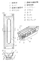
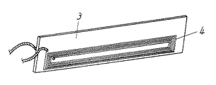
図1は、本発明の一実施の形態のスピーカの構造図を示すものであり、図1(a)は上面図であり、図1(b)は中央部のA−A’における短径方向の断面正面図、図1(c)は断面斜視図、図2は要部である駆動力伝達部材の斜視図である。
【0024】
同図によると、1は振動方向から見た平面形状が長径と短径とを有する細長形のトラック状の振動板であり、2は上記振動板1の外周に内周が固着されたエッジであり、このエッジ2の外周はフレーム11に接着固着されて保持されている。前記振動板1は短径の断面が長径軸終端近傍まで略V字形であり、略逆搭載型半円錐曲面に連なる形状であって、底部折り曲げ部に直線状のスリットを有し、前記直線状のスリットにおいて一枚の板状の駆動力伝達部材3と接合されている。この駆動力伝達部材3は、ガラス繊維複合ポリアミド樹脂シートやアルミなどの金属単板やあるいは、それら単板を表皮およびコア材にしたサンドイッチ構造体などの複合基板から形成されて一段と剛性を高める効果を有している。
【0025】
また前記駆動力伝達部材3の駆動は、前記板状の駆動力伝達部材3の下端部の片面に薄くかつ矩形型リング状に巻回し形成され接合されたボイスコイル4と前記矩形型リング状に形成されたボイスコイル4の振動軸と直交する二箇所のボイスコイル部分のうち一箇所のボイスコイルと、これが挿入される直線状の磁気空隙5を有する磁気回路6によって行われる。
【0026】
磁気回路6はトッププレート7とヨーク9とそれら部材によりサンドイッチされた直方体形状のマグネット8により構成されている。
【0027】
また、10はダンパーであり長径方向のセンターにスリットを有し駆動力伝達部材3が固着されボイスコイル4が前記磁気空隙5に摺接することなく振動可能なように懸垂され、磁気回路6の振動板側に配設されフレーム11に接着固着されている。
【0028】
また、短径方向は長径側終端まで前記駆動力伝達部材3が挿入されるスリットに平行にかつ終端から長径側は半同心円状のコルゲーションを有し、振幅時におけるボイスコイル4の中心保持を行っている。12はダストキャップで振動板1に接着固着されている。
【0029】
以上のように構成されたスピーカの動作について説明する。ボイスコイル4に駆動電流が印加されると磁気空隙5から力を受け、板状の駆動力伝達部材3がピストン運動し、振動板1の長径方向の全長近傍にわたり駆動力を伝達振動し音波が放射されるものである。
【0030】
従って振動板1の短径側はもちろん、長径側においても駆動力伝達部材3から振動板最外周までの距離が短くでき、コーン紙の振動板1の場合、半頂角を最適化できるため振動板1の形状効果により剛性が図られ、駆動力を十分に振動板1に伝達できて素直な平坦な音圧周波数特性が実現でき、またダンパー10のクランプ径が幅広く確保できるために最低共振周波数f0を低く抑えて低音域の再生を可能とするものである。
【0031】
また、矩形型リング状に形成されたボイスコイル4の振動軸と直交する二箇所のボイスコイル4の部分には、駆動力電流が互いに逆向きに流れるため低域信号が印加され振幅が大きくなった場合に逆向きの駆動力により振動板1を制動することができ、過大入力時においてボイスコイル4の底当たりやエッジの突っ張りにおける振動板1の破壊等の耐入力に対する信頼性を向上できる。
【0032】
(実施の形態2)
本発明の実施の形態2を図3により説明する。なお、以降の実施の形態の説明にあたっては実施の形態1と同一部分は同一番号を付与し、説明を省略して説明する。
【0033】
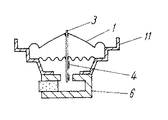
同図によると、実施の形態1との相違点は振動板の形状であり、振動板1は非軸対称形で、かつ、短径の断面が長径軸終端近傍まで略逆V字形としている。指向特性が良好で、かつ素直な平坦な音圧周波数特性が実現できるものであり、また、フレーム11のスピーカ取り付け面から磁気回路6までの距離を短くでき薄型のスピーカを実現するものである。
【0034】
(実施の形態3)
本発明の実施の形態3を図4により説明する。
【0035】
同図によると、実施の形態1との相違点は矩形型リング状に形成されたボイスコイル4が板状の駆動力伝達部材3の下端部の両面にかつ同じ位置に電流が同一方向に流れるように2つのボイスコイル4を接合したものでボイスコイル4の有効線長を長くできスピーカの高能率化が図れる。
【0036】
また、駆動力伝達部材3とボイスコイル4の異種材料の熱線膨張係数が異なると駆動電流による発熱によりバイメタルのごとく駆動力伝達部材3が湾曲する向きに応力が発生するが、両面にかつ同じ位置に接合するため駆動力伝達部材3が湾曲することなく振動するため、高耐入力化が図れる。
【0037】
(実施の形態4)
本発明の実施の形態4を図5により説明する。
【0038】
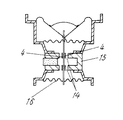
同図によると、実施の形態1との相違点は駆動力源の構成、すなわち磁気回路15の構成とボイスコイル4の位置である。
【0039】
駆動力源は板状の駆動力伝達部材3の中間部の片面に、薄くかつ矩形型リング状に巻回し形成され接合されたボイスコイル4と、前記矩形型リング状に形成され接合されたボイスコイル4の振動軸と直交する二箇所のボイスコイル部分が各々挿入される二箇所の直線状の磁気空隙14を有した磁気回路15とから構成することにより、二箇所の磁気空隙の磁束の方向が互いに反転するため、ボイスコイル4の磁気回路15から受ける駆動力が各々同じ方向に働き大きな駆動力が得られるためスピーカの能率向上が図れる。また駆動力源の背面側に駆動力伝達部材3に固着して振動可能なように懸垂する第2のダンパー16が磁気回路15の底部に固着された第2のフレーム17に接着固着されている。これにより大振幅における駆動力伝達部材3の変形やボイスコイル4の磁気空隙14とのこすれ等に対する信頼性が向上できるものである。
【0040】
(実施の形態5)
本発明の実施の形態5を図6により説明する。
【0041】
同図によると、実施の形態4との相違点は矩形型リング状に形成されたボイスコイル4が板状の駆動力伝達部材3の下端部の両面にかつ同じ位置に電流が同一方向に流れるように2つのボイスコイル線輪を接合したもので前記矩形型リング状に形成され接合されたボイスコイル4の振動軸と直交する四箇所のボイスコイル部分が各々挿入される二箇所の直線状の磁気空隙14より駆動力を受けるためよりスピーカの能率向上が図れる。
【0042】
(実施の形態6)
本発明の実施の形態6を図7により説明する。図7は、本発明の実施の形態6のスピーカの構造を示すものであり、図7(a)は上面図、図7(b)は略中央部のA−A’における短径方向の断面正面図、図7(c)は断面斜視図である。同図によると駆動力源に関し、フレーム11の背面に配し、少なくとも一つの環状磁気空隙18と二箇所のスリット21を設けた円筒状ボイスコイルボビン19の下端部に巻回され、前記磁気空隙18中に懸垂されたボイスコイル20と、前記円筒状ボイスコイルボビン19の上端部に接合された板状の駆動力伝達部材3とから構成するものであり、環状磁気空隙18を有する磁気回路の構成であっても、振動方向から見た平面形状が、長径と短径とを有する細長形の非軸対称形の振動板を板状の駆動力伝達部材を介して駆動できるため、駆動力を十分に振動板に伝達できて素直な平坦な音圧周波数特性が実現できるものである。
【0043】
(実施の形態7)
本発明の実施の形態7を図8により説明する。図8は要部であるボイスコイルボビンと駆動力伝達部材との関係を示す分解斜視図である。
【0044】
同図によると、実施の形態6との相違点はボイスコイル20を下端部に巻回した円筒状ボイスコイルボビン19の上端部に嵌合接合した第2の駆動力伝達部材22を介して、前記第2の駆動力伝達部材22の上端部に長径方向にスリット21を設け、板状の駆動力伝達部材3aと嵌合接合して振動板1を駆動するものであり、板状の駆動力伝達部材3aとの接合面積を大きくすることにより駆動力の損失なく効率的に駆動力を伝達するものである。ボイスコイルボビン19の座屈などがなくより信頼性を向上させることができるものである。
【0045】
(実施の形態8)
本発明の実施の形態8を図9により説明する。図9は、本発明の実施の形態8のスピーカの構造図を示すものであり、図9(a)は一部振動板を取り外した平面図、図9(b)は長径軸における側断面図、図9(c)は短径軸におけるA−A’の断面矢視図、図9(d)はB−B’断面矢視図、図9(e)はC−C’断面矢視図、図9(f)は図9(a)の振動板を取り外した部分からさらに板状駆動力伝達部材を取り外した図でダンパーの部分平面図を示したものである。
【0046】
同図によると、101は振動方向から見た平面形状が長径と短径とを有する長方形又は楕円形、矩形等の非軸対称形の振動板であり、102は上記振動板101の外周に内周が固着されたエッジであり、このエッジ102の外周はフレーム103に固着されて保持されている。
【0047】
上記振動板101は短径の断面が長径軸終端近傍まで略V字形で、B−B’断面からC−C’断面に至る程振動板断面形状の曲率を大きくして半頂角を徐々に大きく(α<β)なっており、略逆搭載型半円錐曲面に連なる形状であって、底部折り曲げ部104に直線状のスリット105を有し、前記直線状のスリット105において一枚の板状駆動力伝達部材106と接合されている。
【0048】
また、円筒状ボイスコイルボビン107は前記振動板101に環状に接合されて直接的に駆動力を伝達するとともに切り込み部108に挿入固着された前記板状駆動力伝達部材106を介して前記振動板101に駆動力を伝達する構成になっている。前記円筒状ボイスコイルボビン107の下端部にはボイスコイル線輪109が巻回されている。
【0049】
ダンパー130はフレーム103に接合される細長形状の外周接合部131と内部に円筒状ボイスコイルボビン107との環状接合部132及び板状駆動力伝達部材106との直線状接合部133にスリット133aを有し、その間の波形形成部において、前記直線状接合部133と平行な少なくとも一つ以上の凸又は凹を繰り返して形成される波形134とそれに連なる半同心円状の凸又は凹を含む波形135に形成し、さらに前記円筒状ボイスコイルボビン107との環状接合部132の外周部に長径軸方向を除いて切り欠き部136を設けて構成している。
【0050】
また、磁気回路140は前記円筒状ボイスコイル線輪109が接触することなく振動可能なように懸垂される環状の磁気空隙141を形成し前記フレーム103に接合されている。前記磁気回路140は防磁型磁気回路構成になっており、トッププレート142とヨーク143とそれら部材によりサンドイッチされたリング状のメインマグネット144と前記ヨーク143の背面に接合され逆着磁されたサブマグネット145とサブマグネットの背面と前記ヨーク143を接続して磁気シールドするヨークカバー146により構成されている。150はボイスコイルボビン上端面に接合されたダストキャップである。
【0051】
以上のように構成されたスピーカの動作について説明する。ボイスコイルボビン107はボイスコイル線輪109に駆動電流が印加されると磁気空隙141から駆動力を受け、ボイスコイルボビン107は直接的に振動板101を駆動するとともに板状駆動力伝達部材106を介して振動板101を駆動するために、振動板101の長径軸終端近傍まで駆動力を伝達振動し音波が放出される。従って振動板101の短径側はもちろん、長径側においても駆動力伝達部材106から振動板最外周までの距離が短くでき駆動力を十分に振動板101に伝達でき、さらに半頂角をα<βとして振動板101を形成する面が捻れているため振動板面の面剛性の向上が図られ振動板101の部分共振による異常音の発生を防止でき、素直な平坦な音圧周波数特性が実現できるとともに、ダンパー130のクランプ径が幅広く確保できるために最低共振周波数f0を低く抑えて低音域の再生を可能とするものである。
【0052】
(実施の形態9)
本発明の実施の形態9を図10により説明する。なお、以降の実施の形態の説明にあたっては実施の形態8と同一部分は同一番号を付与し、説明を省略して説明する。
【0053】
同図において、図10(a)は一部振動板を取り外した平面図、図10(b)は長径軸における側断面図、図10(c)は短径軸におけるA−A’の断面矢視図、図10(d)はB−B’断面矢視図、図10(e)はC−C’断面矢視図、図10(f)は図10(a)の振動板を取り外した部分からさらに板状駆動力伝達部材を取り外した図でダンパーの部分平面図を示したものである。
【0054】
同図によると、実施の形態8との相違点は振動板の形状、そして板状駆動力伝達部材及びダンパーの接合部形状と接合方法にある。101は振動板、106は板状駆動力伝達部材、106aは板状駆動力伝達部材の凸部、L1の二点鎖線は振動板101と板状駆動力伝達部材106の接合線であり、上記振動板101はB−B’断面からC−C’断面に至る程振動板の全高が浅く形成されて半頂角が徐々に大きく(α<β)なり、振動板101を形成する面が捻れ、振動板面の面剛性の向上が図られ振動板101の部分共振による異常音の発生を防止できるものである。
【0055】
ダンパー130における実施の形態8との相違点は前記円筒状ボイスコイルボビン107との環状接合部132及び板状駆動力伝達部材106との直線状接合部133にスリット133bの形状と接合法にあり、前記板状駆動力伝達部材106の下端部に凸部106aを形成して前記環状接合部132近傍での接合部をなくしたために前記環状接合部132は連続的な環状を形成することができ、さらに板状駆動力伝達部材の凸部106aと直線状接合部133のスリット133bの接合を前記凸部106aを挿入して接合する構成により、環状接合部が円周方向に切断されることがなく、ボイスコイルボビン107を環状接合部に挿入してもダンパー130が短径方向に開くことがなく作業性が改善できるとともに、ボイスコイルボビン107の中心保持性のさらなる向上が図れるものであり、素直な平坦な音圧周波数特性が実現できるとともに、円筒状ボイスコイル駆動でありながらダンパー130のクランプ径が幅広く確保できるために最低共振周波数f0を低く抑えて低音域の再生を可能とするものである。
【0056】
(実施の形態10)
本発明の実施の形態10を図11により説明する。尚実施の形態6または実施の形態9と同一部分は同一番号を付与し、説明を省略して説明する。
【0057】
同図において、図11(a)は一部振動板を取り外した平面図、図11(b)は長径軸における側断面図、図11(c)は短径軸におけるA−A’断面矢視図、図11(d)はB−B’断面矢視図を示したものである。
【0058】
同図によると、実施の形態6との相違点はダンパーが円筒状ボイスコイルボビン及び板状の駆動力伝達部材の双方を支持している点と振動板の面剛性向上を図っている点であり、101は振動板、102はエッジ、103はフレームで上記振動板101は短径の断面が長径軸終端近傍まで略V字形で、A−A’断面からB−B’断面に至る程振動板の全高が浅く形成されていて半頂角が徐々に大きくなり、長軸側で略逆搭載型半円錐曲面に連なる形状であって、底部折り曲げ部104に直線状のスリット105を有し、前記直線状のスリット105において一枚の板状駆動力伝達部材106と接合されている。
【0059】
また、107は円筒状ボイスコイルボビンで切り込み部108に前記板状駆動力伝達部材106が挿入固着され、そして振動板101にはダストキャップ150aが接合されている構成により、振動板101を形成する面が捻れ、振動板面の面剛性の向上が図られ振動板の部分共振による異常音の発生を防止できるものであり、さらにダンパーは、中心部に連続形成される円筒状ボイスコイルボビン107との環状接合部と長径軸方向に板状駆動力伝達部材106の双方を懸垂支持するために、中心保持性のさらなる向上が図れるものであり、素直な平坦な音圧周波数特性が実現できるとともに、ダンパー130のクランプ径が幅広く確保できるために最低共振周波数f0を低く抑えて低音域の再生を可能とするものである。尚本実施の形態においてダストキャップを接合しているがこれはなくても技術的内容が変わるものではない。
【0060】
(実施の形態11)
本発明の実施の形態11を図12により説明する。尚実施の形態9と同一部分は同一番号を付与し、説明を省略して説明する。同図において、図12(a)は一部振動板を取り外した平面図、図12(b)は長径軸における側断面図、図12(c)は短径軸におけるA−A’の断面矢視図、図12(d)はB−B’断面矢視図を示したものである。
【0061】
同図によると、実施の形態9との相違点は駆動力源である環状の磁気空隙を有する磁気回路及び環状のボイスコイルボビンが2個長軸径方向に間隔を置いて設けた点である。101aは二つの円形の透孔を有する振動板、30a,30bは環状の磁気空隙を有する磁気回路、107a,107bは円筒状ボイスコイルボビンであり、前記円筒状ボイスコイルボビン107a,107bの切り込み部108a,108bに前記板状駆動力伝達部材106が挿入固着されているとともに、両円筒状ボイスコイルボビン107a,107bおよび駆動力伝達部材106を介して振動板101aを駆動する構成により、さらなる中高音域再生の向上が図れるものである。
【0062】
なお、上記各実施の形態においてはスピーカの細長形のトラック形状のものとして説明したが、矩形型形状のものであれば長円形や、楕円形のスピーカでも同様の効果を有するものであり、本発明の技術的範疇であることは勿論である。
【0063】
また、本発明によって駆動力伝達部材を板状のものとして扱えるので、従来のボイスコイルボビンを使用したものでは振動板の周辺との距離に大きなバラツキを有していたものを、バラツキを抑制できて従来のコーン形スピーカ以外でも素直な平坦な周波数特性のスピーカを得ることができ、多彩な形状のスピーカをも提供可能とするものである。
【0064】
【発明の効果】
以上のように本発明のスピーカは、振動板に結合されるとともに磁気回路の磁気空隙にはめ込まれるボイスコイル部を有する板状の駆動力伝達部材を用いたことによって、振動板の周辺との距離のバラツキを抑制して素直な平坦な音圧周波数特性のスピーカを得ることができ、多彩な形状のスピーカをも提供可能とするものである。
【図面の簡単な説明】
【図1】 (a)本発明のスピーカの一実施の形態の上面図
(b)同短径方向の側断面図
(c)同断面斜視図
【図2】 同要部である駆動力伝達部材の斜視図
【図3】 同実施の形態2の側断面図
【図4】 同実施の形態3の側断面図
【図5】 同実施の形態4の側断面図
【図6】 同実施の形態5の側断面図
【図7】 (a)同実施の形態6の上面図
(b)同短径方向の側断面図
(c)同断面斜視図
【図8】 同実施の形態7におけるボイスコイルボビンと駆動力伝達部材の分解斜視図
【図9】 (a)同実施の形態8の一部振動板を取り外した上面図
(b)同長径方向の側断面図
(c)同短径方向のA−A’断面矢視図
(d)同B−B’断面矢視図
(e)同C−C’断面矢視図
(f)板状駆動力伝達部材までを取り外した上面図
【図10】 (a)同実施の形態9の一部振動板を取り外した上面図
(b)同長径方向の側断面図
(c)同短径方向のA−A’断面矢視図
(d)同B−B’断面矢視図
(e)同C−C’断面矢視図
(f)板状駆動力伝達部材までを取り外した上面図
【図11】 (a)同実施の形態10の一部振動板を取り外した上面図
(b)同長径方向の側断面図
(c)同短径方向のA−A’断面矢視図
(d)同B−B’断面矢視図
【図12】 (a)同実施の形態11の一部振動板を取り外した上面図
(b)同長径方向の側断面図
(c)同短径方向のA−A’断面矢視図
(d)同B−B’断面矢視図
【図13】 (a)従来のスピーカの上面図
(b)同長径方向の断面図
(c)同短径方向の断面図
【符号の説明】
1,101,101a 振動板
2,102 エッジ
3,3a 駆動力伝達部材
4 ボイスコイル
5 直線状の磁気空隙
6 磁気回路
7 トッププレート
8 マグネット
9 ヨーク
10 ダンパー
11,103 フレーム
12 ダストキャップ
14 直線状の磁気空隙
15 磁気回路
16 第2のダンパー
17 第2のフレーム
18,141 環状磁気空隙
19,107,107a,107b 円筒状ボイスコイルボビン
20 ボイスコイル
21,133a,133b スリット
22 第2の駆動力伝達部材[0001]
BACKGROUND OF THE INVENTION
The present invention relates to a speaker having an elongated structure used for various types of audio equipment, particularly video audio equipment.
[0002]
[Prior art]
Speakers used in audiovisual equipment are mounted on both sides of the cathode ray tube, and so long and narrow speakers such as rectangular and elliptical have been used for audiovisual equipment. As a result, it is required to further reduce the width of the speaker, and there is a demand for higher sound quality corresponding to higher image quality on the screen.
[0003]
Here, a conventional elongated speaker will be described with reference to FIGS. 13 (a) to 13 (c).
[0004]
FIG. 13A is a plan view of a conventional elongated speaker, FIG. 13B is a side sectional view in the same major axis direction, and FIG. 13C is a side sectional view in the same minor axis direction.
[0005]
According to the figure,
[0006]
A
[0007]
On the other hand, a
[0008]
[Problems to be solved by the invention]
However, the above-mentioned speaker (1) has a structure in which the central portion of the
[0009]
(2) Since the
[0010]
The present invention solves the above-mentioned conventional problems, and although it has an elongated structure, it is difficult to cause split resonance, and a flat frequency characteristic is obtained, and the lowest resonance frequency f0 can be suppressed to be low, enabling reproduction of a low sound range. The present invention provides a speaker with excellent sound quality.
[0011]
[Means for Solving the Problems]
In order to solve the above problems, the speaker of the present invention has at least Straight in the center A magnetic circuit having a magnetic gap, a frame attached to the magnetic circuit, and a frame Through the edge As the perimeter is joined , The planar shape seen from the vibration direction has a major axis and a minor axis. Either square or track or oval or oval Inserted and joined to the diaphragm and a slit of the diaphragm provided on the substantially major axis of the diaphragm A plate-like driving force transmission member; Fits in magnetic gap Provided on the plate-like driving force transmission member Voice carp And the above A slit into which the plate-like driving force transmission member is inserted And a damper provided with a track-shaped corrugation parallel to the slit on both sides of the slit, and a joint portion of the plate-like driving force transmission member with the diaphragm, the voice coil, The plate-like driving force transmission member and the damper are joined in the slit at a position between and the outer periphery of the damper is joined to the frame The distance from the driving force transmission member to the outermost periphery of the diaphragm can be shortened not only on the short diameter side but also on the long diameter side, and the driving force can be sufficiently transmitted to the diaphragm so that the flat and flat sound pressure frequency characteristics Is realized, By joining the outer periphery to the frame and inserting and joining the plate-like driving force transmission member to the slit provided in the damper A wide clamp diameter of the damper is secured, and the lowest resonance frequency f0 is kept low to enable reproduction in the low sound range.
[0012]
DETAILED DESCRIPTION OF THE INVENTION
The invention according to
[0013]
The invention according to
[0014]
The invention according to
[0015]
The invention according to
[0016]
According to a fifth aspect of the present invention, in the speaker according to any one of the first to third aspects, the diaphragm has a short diameter cross section having a long diameter. In the direction Abbreviated V shape This forms the bent part of this A straight slit at the bent part Establishment The major axis in the cross-sectional shape of the diaphragm Direction Long diameter from center Direction Increasing the curvature of the cross section curve toward the end and gradually increasing the half apex angle And Can avoid the formation of a flat part on the cone paper surface forming the diaphragm, can improve the rigidity strength of the flat part of the diaphragm, and can prevent the generation of abnormal noise due to local resonance generated in the flat part It is.
[0017]
According to a sixth aspect of the present invention, in the speaker according to any one of the first to third aspects, the diaphragm has a short diameter cross section having a long diameter. In the direction Abbreviated V shape This forms the bent part of this By making the bent part as shallow as possible to the end of the major axis, the half apex angle can be gradually increased, the cone paper surface forming the diaphragm can be twisted, and the formation of the flat part can be avoided. The rigidity of the flat portion of the plate is improved, and abnormal noise due to local resonance occurring in the flat portion can be prevented.
[0021]
According to a seventh aspect of the present invention, in the speaker according to the second aspect, the damper includes an annular joint portion with a cylindrical voice coil bobbin at the center and a plate-like driving force transmission member in the major axis direction. Inserted Fixed plural Straight joint with slit And providing The slit is spaced from the annular joint. Formed, The annular joint is not cut in the circumferential direction, and even if a voice coil bobbin is inserted into the annular joint, the damper does not open in the minor axis direction, improving workability and further improving the center retainability. It can be planned.
[0022]
Hereinafter, an embodiment of a speaker according to the present invention will be described with reference to FIGS.
[0023]
(Embodiment 1)
FIG. 1 is a structural diagram of a speaker according to an embodiment of the present invention, FIG. 1 (a) is a top view, and FIG. 1 (b) is a minor axis direction at AA ′ in the central portion. FIG. 1C is a cross-sectional perspective view, and FIG. 2 is a perspective view of a driving force transmitting member as a main part.
[0024]
According to the figure,
[0025]
Further, the driving
[0026]
The
[0027]
[0028]
Further, the minor axis direction is parallel to the slit into which the driving
[0029]
The operation of the speaker configured as above will be described. When a drive current is applied to the
[0030]
Therefore, the distance from the driving
[0031]
Further, since the driving force current flows in opposite directions to the two portions of the
[0032]
(Embodiment 2)
A second embodiment of the present invention will be described with reference to FIG. In the following description of the embodiment, the same parts as those in the first embodiment will be given the same reference numerals and description thereof will be omitted.
[0033]
According to the figure, the difference from the first embodiment is the shape of the diaphragm. The
[0034]
(Embodiment 3)
A third embodiment of the present invention will be described with reference to FIG.
[0035]
According to the figure, the difference from the first embodiment is that the
[0036]
Also, if the thermal expansion coefficients of different materials of the driving
[0037]
(Embodiment 4)
A fourth embodiment of the present invention will be described with reference to FIG.
[0038]
According to the figure, the difference from the first embodiment is the configuration of the driving force source, that is, the configuration of the
[0039]
The driving force source is a
[0040]
(Embodiment 5)
Embodiment 5 of the present invention will be described with reference to FIG.
[0041]
According to the figure, the difference from the fourth embodiment is that the
[0042]
(Embodiment 6)
A sixth embodiment of the present invention will be described with reference to FIG. 7A and 7B show the structure of the speaker according to the sixth embodiment of the present invention. FIG. 7A is a top view, and FIG. 7B is a cross-section in the minor axis direction at AA ′ at a substantially central portion. A front view and FIG.7 (c) are cross-sectional perspective views. According to the figure, the driving force source is wound around the lower end portion of a cylindrical
[0043]
(Embodiment 7)
A seventh embodiment of the present invention will be described with reference to FIG. FIG. 8 is an exploded perspective view showing the relationship between the voice coil bobbin, which is a main part, and the driving force transmission member.
[0044]
According to the figure, the difference from the sixth embodiment is that the second driving
[0045]
(Embodiment 8)
An eighth embodiment of the present invention will be described with reference to FIG. FIG. 9 shows a structural diagram of the loudspeaker according to
[0046]
According to the figure,
[0047]
The
[0048]
Further, the cylindrical
[0049]
The
[0050]
Further, the
[0051]
The operation of the speaker configured as above will be described. The
[0052]
(Embodiment 9)
A ninth embodiment of the present invention will be described with reference to FIG. In the following description of the embodiment, the same parts as those in the eighth embodiment will be given the same reference numerals, and description thereof will be omitted.
[0053]
10A is a plan view with a part of the diaphragm removed, FIG. 10B is a side sectional view of the major axis, and FIG. 10C is an AA ′ sectional arrow of the minor axis. FIG. 10 (d) is a cross-sectional view taken along the line BB ′, FIG. 10 (e) is a cross-sectional view taken along the line CC ′, and FIG. 10 (f) is a diagram where the diaphragm of FIG. 10 (a) is removed. FIG. 5 is a partial plan view of a damper in a view in which a plate-like driving force transmission member is further removed from the portion.
[0054]
According to the figure, the difference from the eighth embodiment is the shape of the diaphragm, and the shape and method of joining the plate-like driving force transmission member and the damper. 101 is a vibration plate, 106 is a plate-like driving force transmission member, 106a is a convex portion of the plate-like driving force transmission member, and a two-dot chain line L1 is a joint line between the
[0055]
The difference between the
[0056]
(Embodiment 10)
A tenth embodiment of the present invention will be described with reference to FIG. In addition, the same part as
[0057]
11A is a plan view with a part of the diaphragm removed, FIG. 11B is a side sectional view of the major axis, and FIG. 11C is an AA ′ sectional view of the minor axis. FIG. 11 (d) shows a cross-sectional view taken along the line BB ′.
[0058]
According to the figure, the difference from the sixth embodiment is that the damper supports both the cylindrical voice coil bobbin and the plate-like driving force transmission member, and the surface rigidity of the diaphragm is improved. , 101 is a diaphragm, 102 is an edge, 103 is a frame, and the
[0059]
[0060]
(Embodiment 11)
An eleventh embodiment of the present invention will be described with reference to FIG. The same parts as those of the ninth embodiment are given the same numbers, and the description thereof will be omitted. 12 (a) is a plan view with a part of the diaphragm removed, FIG. 12 (b) is a side sectional view on the major axis, and FIG. 12 (c) is an AA ′ sectional arrow on the minor axis. FIG. 12D is a view taken along the line BB ′.
[0061]
According to the figure, the difference from the ninth embodiment is that two magnetic circuits having an annular magnetic gap as a driving force source and two annular voice coil bobbins are provided at intervals in the major axis radial direction. 101a is a diaphragm having two circular through holes, 30a and 30b are magnetic circuits having an annular magnetic gap, 107a and 107b are cylindrical voice coil bobbins, and the
[0062]
In each of the above embodiments, the speaker has been described as having an elongated track shape. However, if the speaker has a rectangular shape, an elliptical or elliptical speaker has the same effect. Of course, it is a technical category of the invention.
[0063]
In addition, since the driving force transmission member can be handled as a plate-like member according to the present invention, a conventional voice coil bobbin that has a large variation in the distance from the periphery of the diaphragm can suppress the variation. In addition to the conventional cone-shaped speaker, it is possible to obtain a speaker having a flat and flat frequency characteristic, and to provide a speaker having various shapes.
[0064]
【The invention's effect】
As described above, the speaker according to the present invention uses a plate-like driving force transmission member that has a voice coil portion that is coupled to the diaphragm and fitted in the magnetic gap of the magnetic circuit, so that the distance from the periphery of the diaphragm Accordingly, it is possible to obtain a speaker having a flat and flat sound pressure frequency characteristic by suppressing the variation of the above, and to provide a speaker having various shapes.
[Brief description of the drawings]
FIG. 1A is a top view of an embodiment of a speaker of the present invention.
(B) Side sectional view in the same minor axis direction
(C) Perspective sectional view
FIG. 2 is a perspective view of a driving force transmission member that is the main part of the same.
FIG. 3 is a side sectional view of the second embodiment.
FIG. 4 is a side sectional view of the third embodiment.
FIG. 5 is a side sectional view of the fourth embodiment.
FIG. 6 is a side sectional view of the fifth embodiment.
7A is a top view of the sixth embodiment. FIG.
(B) Side sectional view in the same minor axis direction
(C) Perspective sectional view
FIG. 8 is an exploded perspective view of a voice coil bobbin and a driving force transmission member according to the seventh embodiment.
FIG. 9A is a top view with the partial diaphragm of the eighth embodiment removed.
(B) Side sectional view in the same major axis direction
(C) AA ′ cross-sectional view in the same minor axis direction
(D) BB 'cross-sectional arrow view
(E) CC 'cross-sectional arrow view
(F) Top view with the plate-like driving force transmission member removed
FIG. 10A is a top view with the partial diaphragm of the ninth embodiment removed.
(B) Side sectional view in the same major axis direction
(C) AA ′ cross-sectional view in the same minor axis direction
(D) BB 'cross-sectional arrow view
(E) CC 'cross-sectional arrow view
(F) Top view with the plate-like driving force transmission member removed
11A is a top view of the tenth embodiment with a partial diaphragm removed. FIG.
(B) Side sectional view in the same major axis direction
(C) AA ′ cross-sectional view in the same minor axis direction
(D) BB 'cross-sectional arrow view
12 (a) is a top view with the partial vibration plate of
(B) Side sectional view in the same major axis direction
(C) AA ′ cross-sectional view in the same minor axis direction
(D) BB 'cross-sectional arrow view
13A is a top view of a conventional speaker. FIG.
(B) Cross section in the same major axis direction
(C) Cross section in the same minor axis direction
[Explanation of symbols]
1,101,101a Diaphragm
2,102 edges
3, 3a Driving force transmission member
4 Voice coil
5 Linear magnetic gap
6 Magnetic circuit
7 Top plate
8 Magnet
9 York
10 Damper
11,103 frames
12 Dust cap
14 Linear magnetic gap
15 Magnetic circuit
16 Second damper
17 Second frame
18,141 annular magnetic gap
19, 107, 107a, 107b Cylindrical voice coil bobbin
20 Voice coil
21, 133a, 133b Slit
22 Second driving force transmission member
Claims (7)
Priority Applications (1)
| Application Number | Priority Date | Filing Date | Title |
|---|---|---|---|
| JP28809897A JP3893694B2 (en) | 1996-10-30 | 1997-10-21 | Speaker |
Applications Claiming Priority (3)
| Application Number | Priority Date | Filing Date | Title |
|---|---|---|---|
| JP8-287875 | 1996-10-30 | ||
| JP28787596 | 1996-10-30 | ||
| JP28809897A JP3893694B2 (en) | 1996-10-30 | 1997-10-21 | Speaker |
Publications (2)
| Publication Number | Publication Date |
|---|---|
| JPH10191494A JPH10191494A (en) | 1998-07-21 |
| JP3893694B2 true JP3893694B2 (en) | 2007-03-14 |
Family
ID=26556920
Family Applications (1)
| Application Number | Title | Priority Date | Filing Date |
|---|---|---|---|
| JP28809897A Expired - Fee Related JP3893694B2 (en) | 1996-10-30 | 1997-10-21 | Speaker |
Country Status (1)
| Country | Link |
|---|---|
| JP (1) | JP3893694B2 (en) |
Cited By (4)
| Publication number | Priority date | Publication date | Assignee | Title |
|---|---|---|---|---|
| CN103222281A (en) * | 2010-08-17 | 2013-07-24 | 埃克塞尔威公司 | Vibration-lead plate for flat type speaker, mounted between voice coil plate and vibration plate |
| US9641938B2 (en) | 2015-05-21 | 2017-05-02 | Bose Corporation | Electro-acoustic transducer with radiating acoustic seal and stacked magnetic circuit assembly |
| US10499158B2 (en) | 2015-05-19 | 2019-12-03 | Bose Corporation | Electro-acoustic transducer with radiating acoustic seal and stacked magnetic circuit assembly |
| US11184712B2 (en) | 2015-05-19 | 2021-11-23 | Bose Corporation | Dual-field single-voice-coil transducer |
Families Citing this family (23)
| Publication number | Priority date | Publication date | Assignee | Title |
|---|---|---|---|---|
| US6714655B2 (en) | 2001-05-11 | 2004-03-30 | Matsushita Electric Industrial Co., Ltd. | Speaker |
| WO2003063544A1 (en) * | 2002-01-24 | 2003-07-31 | Matsushita Electric Industrial Co., Ltd. | Diaphragm for speaker and polyamide-imide resin and polyimide resin for the same |
| EP1377115B1 (en) | 2002-06-24 | 2016-01-06 | Panasonic Intellectual Property Management Co., Ltd. | Loudspeaker diaphragm |
| EP1519621B1 (en) | 2003-08-19 | 2008-04-30 | Matsushita Electric Industrial Co., Ltd. | Loudspeaker |
| JP4473068B2 (en) * | 2003-08-19 | 2010-06-02 | パナソニック株式会社 | Speaker |
| JP2006271261A (en) * | 2005-03-29 | 2006-10-12 | Kyoto Life Science Kenkyusho:Kk | Antioxidant health food |
| JP4687400B2 (en) * | 2005-11-07 | 2011-05-25 | ソニー株式会社 | Speaker device |
| JP4677341B2 (en) * | 2005-12-21 | 2011-04-27 | パイオニア株式会社 | Speaker device and mobile phone |
| JP2007174233A (en) | 2005-12-21 | 2007-07-05 | Pioneer Electronic Corp | Speaker instrument and portable telephone |
| JP4603972B2 (en) * | 2005-12-21 | 2010-12-22 | パイオニア株式会社 | Diaphragm for speaker device, speaker device, and mobile phone |
| JP4867442B2 (en) | 2006-04-10 | 2012-02-01 | パナソニック株式会社 | Speaker diaphragm and speaker using the same |
| JP4534173B2 (en) * | 2008-04-15 | 2010-09-01 | ソニー株式会社 | Speaker, voice coil unit and manufacturing method thereof |
| JP5311053B2 (en) * | 2009-11-26 | 2013-10-09 | オンキヨー株式会社 | Electrodynamic speaker |
| KR101154252B1 (en) * | 2010-11-29 | 2012-06-13 | 주식회사 엑셀웨이 | Damper of voice coil plate for flat type speaker |
| KR101119499B1 (en) | 2011-02-16 | 2012-02-28 | 주식회사 엑셀웨이 | Flat type speaker having damper-lead plate mounted on diaphragm |
| JP6123838B2 (en) | 2014-09-29 | 2017-05-10 | ヤマハ株式会社 | Electroacoustic transducer |
| WO2016052022A1 (en) * | 2014-09-29 | 2016-04-07 | ヤマハ株式会社 | Electroacoustic transducer |
| WO2016110992A1 (en) * | 2015-01-09 | 2016-07-14 | ヤマハ株式会社 | Electroacoustic transducer |
| WO2016110991A1 (en) * | 2015-01-09 | 2016-07-14 | ヤマハ株式会社 | Electroacoustic transducer |
| KR101710861B1 (en) * | 2015-10-02 | 2017-02-28 | 주식회사 에이치엠링크 | A two-way speaker equipped with a bar magnet |
| CN209767821U (en) * | 2019-06-20 | 2019-12-10 | 苏州上声电子股份有限公司 | loudspeaker driven by multipath input |
| CN210053564U (en) * | 2019-07-02 | 2020-02-11 | 苏州茹声电子有限公司 | Multi-input driven loudspeaker |
| CN110225440A (en) * | 2019-07-15 | 2019-09-10 | 苏州茹声电子有限公司 | A kind of loudspeaker of multichannel input driving |
-
1997
- 1997-10-21 JP JP28809897A patent/JP3893694B2/en not_active Expired - Fee Related
Cited By (4)
| Publication number | Priority date | Publication date | Assignee | Title |
|---|---|---|---|---|
| CN103222281A (en) * | 2010-08-17 | 2013-07-24 | 埃克塞尔威公司 | Vibration-lead plate for flat type speaker, mounted between voice coil plate and vibration plate |
| US10499158B2 (en) | 2015-05-19 | 2019-12-03 | Bose Corporation | Electro-acoustic transducer with radiating acoustic seal and stacked magnetic circuit assembly |
| US11184712B2 (en) | 2015-05-19 | 2021-11-23 | Bose Corporation | Dual-field single-voice-coil transducer |
| US9641938B2 (en) | 2015-05-21 | 2017-05-02 | Bose Corporation | Electro-acoustic transducer with radiating acoustic seal and stacked magnetic circuit assembly |
Also Published As
| Publication number | Publication date |
|---|---|
| JPH10191494A (en) | 1998-07-21 |
Similar Documents
| Publication | Publication Date | Title |
|---|---|---|
| JP3893694B2 (en) | Speaker | |
| US6594372B2 (en) | Electroacoustic transducer | |
| US6493452B1 (en) | Speaker unit | |
| JP2016072955A (en) | Electroacoustic transducer | |
| JP2015119471A (en) | Electroacoustic transducer | |
| JP6482004B2 (en) | Speaker | |
| US10142736B2 (en) | Electroacoustic transducer | |
| JP3139915B2 (en) | Speaker | |
| JP3820717B2 (en) | Speaker | |
| JPH11150790A (en) | Speaker | |
| JP3582201B2 (en) | Speaker | |
| JP3613881B2 (en) | Speaker | |
| JP3629777B2 (en) | Speaker | |
| JP3601176B2 (en) | Speaker | |
| JPH10322795A (en) | Speaker device | |
| JP3132323B2 (en) | Loudspeaker and its manufacturing method | |
| JP2015109578A (en) | Electroacoustic transducer | |
| JPS6019419Y2 (en) | composite speaker | |
| JP2003023695A (en) | Speaker system | |
| JP3617154B2 (en) | Speaker | |
| JP5037723B2 (en) | Speaker device | |
| JP2000308194A (en) | Loudspeaker system | |
| JP6187666B2 (en) | Electroacoustic transducer | |
| JP3456131B2 (en) | Speaker | |
| JP4456925B2 (en) | Speaker device |
Legal Events
| Date | Code | Title | Description |
|---|---|---|---|
| RD01 | Notification of change of attorney |
Free format text: JAPANESE INTERMEDIATE CODE: A7421 Effective date: 20050624 |
|
| A977 | Report on retrieval |
Free format text: JAPANESE INTERMEDIATE CODE: A971007 Effective date: 20050913 |
|
| A131 | Notification of reasons for refusal |
Free format text: JAPANESE INTERMEDIATE CODE: A131 Effective date: 20051004 |
|
| A521 | Written amendment |
Free format text: JAPANESE INTERMEDIATE CODE: A523 Effective date: 20051202 |
|
| A131 | Notification of reasons for refusal |
Free format text: JAPANESE INTERMEDIATE CODE: A131 Effective date: 20060530 |
|
| A521 | Written amendment |
Free format text: JAPANESE INTERMEDIATE CODE: A523 Effective date: 20060731 |
|
| A131 | Notification of reasons for refusal |
Free format text: JAPANESE INTERMEDIATE CODE: A131 Effective date: 20060829 |
|
| A521 | Written amendment |
Free format text: JAPANESE INTERMEDIATE CODE: A523 Effective date: 20061030 |
|
| TRDD | Decision of grant or rejection written | ||
| A01 | Written decision to grant a patent or to grant a registration (utility model) |
Free format text: JAPANESE INTERMEDIATE CODE: A01 Effective date: 20061121 |
|
| A61 | First payment of annual fees (during grant procedure) |
Free format text: JAPANESE INTERMEDIATE CODE: A61 Effective date: 20061204 |
|
| FPAY | Renewal fee payment (event date is renewal date of database) |
Free format text: PAYMENT UNTIL: 20091222 Year of fee payment: 3 |
|
| FPAY | Renewal fee payment (event date is renewal date of database) |
Free format text: PAYMENT UNTIL: 20101222 Year of fee payment: 4 |
|
| FPAY | Renewal fee payment (event date is renewal date of database) |
Free format text: PAYMENT UNTIL: 20101222 Year of fee payment: 4 |
|
| FPAY | Renewal fee payment (event date is renewal date of database) |
Free format text: PAYMENT UNTIL: 20111222 Year of fee payment: 5 |
|
| FPAY | Renewal fee payment (event date is renewal date of database) |
Free format text: PAYMENT UNTIL: 20111222 Year of fee payment: 5 |
|
| FPAY | Renewal fee payment (event date is renewal date of database) |
Free format text: PAYMENT UNTIL: 20121222 Year of fee payment: 6 |
|
| FPAY | Renewal fee payment (event date is renewal date of database) |
Free format text: PAYMENT UNTIL: 20121222 Year of fee payment: 6 |
|
| FPAY | Renewal fee payment (event date is renewal date of database) |
Free format text: PAYMENT UNTIL: 20131222 Year of fee payment: 7 |
|
| LAPS | Cancellation because of no payment of annual fees |