JP3893381B2 - Measuring device and measuring method for measuring an electrical signal emitted from a biological sample - Google Patents
Measuring device and measuring method for measuring an electrical signal emitted from a biological sample Download PDFInfo
- Publication number
- JP3893381B2 JP3893381B2 JP2003546094A JP2003546094A JP3893381B2 JP 3893381 B2 JP3893381 B2 JP 3893381B2 JP 2003546094 A JP2003546094 A JP 2003546094A JP 2003546094 A JP2003546094 A JP 2003546094A JP 3893381 B2 JP3893381 B2 JP 3893381B2
- Authority
- JP
- Japan
- Prior art keywords
- communication pipe
- measuring device
- well
- flow path
- microelectrode
- Prior art date
- Legal status (The legal status is an assumption and is not a legal conclusion. Google has not performed a legal analysis and makes no representation as to the accuracy of the status listed.)
- Expired - Lifetime
Links
Images


Classifications
-
- G—PHYSICS
- G01—MEASURING; TESTING
- G01N—INVESTIGATING OR ANALYSING MATERIALS BY DETERMINING THEIR CHEMICAL OR PHYSICAL PROPERTIES
- G01N33/00—Investigating or analysing materials by specific methods not covered by groups G01N1/00 - G01N31/00
- G01N33/48—Biological material, e.g. blood, urine; Haemocytometers
- G01N33/483—Physical analysis of biological material
- G01N33/487—Physical analysis of biological material of liquid biological material
- G01N33/48707—Physical analysis of biological material of liquid biological material by electrical means
- G01N33/48728—Investigating individual cells, e.g. by patch clamp, voltage clamp
-
- B—PERFORMING OPERATIONS; TRANSPORTING
- B01—PHYSICAL OR CHEMICAL PROCESSES OR APPARATUS IN GENERAL
- B01L—CHEMICAL OR PHYSICAL LABORATORY APPARATUS FOR GENERAL USE
- B01L3/00—Containers or dishes for laboratory use, e.g. laboratory glassware; Droppers
- B01L3/50—Containers for the purpose of retaining a material to be analysed, e.g. test tubes
- B01L3/502—Containers for the purpose of retaining a material to be analysed, e.g. test tubes with fluid transport, e.g. in multi-compartment structures
- B01L3/5027—Containers for the purpose of retaining a material to be analysed, e.g. test tubes with fluid transport, e.g. in multi-compartment structures by integrated microfluidic structures, i.e. dimensions of channels and chambers are such that surface tension forces are important, e.g. lab-on-a-chip
- B01L3/502761—Containers for the purpose of retaining a material to be analysed, e.g. test tubes with fluid transport, e.g. in multi-compartment structures by integrated microfluidic structures, i.e. dimensions of channels and chambers are such that surface tension forces are important, e.g. lab-on-a-chip specially adapted for handling suspended solids or molecules independently from the bulk fluid flow, e.g. for trapping or sorting beads, for physically stretching molecules
-
- B—PERFORMING OPERATIONS; TRANSPORTING
- B01—PHYSICAL OR CHEMICAL PROCESSES OR APPARATUS IN GENERAL
- B01L—CHEMICAL OR PHYSICAL LABORATORY APPARATUS FOR GENERAL USE
- B01L2200/00—Solutions for specific problems relating to chemical or physical laboratory apparatus
- B01L2200/02—Adapting objects or devices to another
- B01L2200/026—Fluid interfacing between devices or objects, e.g. connectors, inlet details
-
- B—PERFORMING OPERATIONS; TRANSPORTING
- B01—PHYSICAL OR CHEMICAL PROCESSES OR APPARATUS IN GENERAL
- B01L—CHEMICAL OR PHYSICAL LABORATORY APPARATUS FOR GENERAL USE
- B01L2200/00—Solutions for specific problems relating to chemical or physical laboratory apparatus
- B01L2200/06—Fluid handling related problems
- B01L2200/0647—Handling flowable solids, e.g. microscopic beads, cells, particles
-
- B—PERFORMING OPERATIONS; TRANSPORTING
- B01—PHYSICAL OR CHEMICAL PROCESSES OR APPARATUS IN GENERAL
- B01L—CHEMICAL OR PHYSICAL LABORATORY APPARATUS FOR GENERAL USE
- B01L2300/00—Additional constructional details
- B01L2300/06—Auxiliary integrated devices, integrated components
- B01L2300/0627—Sensor or part of a sensor is integrated
- B01L2300/0645—Electrodes
-
- B—PERFORMING OPERATIONS; TRANSPORTING
- B01—PHYSICAL OR CHEMICAL PROCESSES OR APPARATUS IN GENERAL
- B01L—CHEMICAL OR PHYSICAL LABORATORY APPARATUS FOR GENERAL USE
- B01L2300/00—Additional constructional details
- B01L2300/08—Geometry, shape and general structure
- B01L2300/0809—Geometry, shape and general structure rectangular shaped
- B01L2300/0816—Cards, e.g. flat sample carriers usually with flow in two horizontal directions
-
- B—PERFORMING OPERATIONS; TRANSPORTING
- B01—PHYSICAL OR CHEMICAL PROCESSES OR APPARATUS IN GENERAL
- B01L—CHEMICAL OR PHYSICAL LABORATORY APPARATUS FOR GENERAL USE
- B01L2300/00—Additional constructional details
- B01L2300/08—Geometry, shape and general structure
- B01L2300/0887—Laminated structure
-
- B—PERFORMING OPERATIONS; TRANSPORTING
- B01—PHYSICAL OR CHEMICAL PROCESSES OR APPARATUS IN GENERAL
- B01L—CHEMICAL OR PHYSICAL LABORATORY APPARATUS FOR GENERAL USE
- B01L2300/00—Additional constructional details
- B01L2300/14—Means for pressure control
-
- B—PERFORMING OPERATIONS; TRANSPORTING
- B01—PHYSICAL OR CHEMICAL PROCESSES OR APPARATUS IN GENERAL
- B01L—CHEMICAL OR PHYSICAL LABORATORY APPARATUS FOR GENERAL USE
- B01L2300/00—Additional constructional details
- B01L2300/18—Means for temperature control
- B01L2300/1805—Conductive heating, heat from thermostatted solids is conducted to receptacles, e.g. heating plates, blocks
- B01L2300/1827—Conductive heating, heat from thermostatted solids is conducted to receptacles, e.g. heating plates, blocks using resistive heater
-
- B—PERFORMING OPERATIONS; TRANSPORTING
- B01—PHYSICAL OR CHEMICAL PROCESSES OR APPARATUS IN GENERAL
- B01L—CHEMICAL OR PHYSICAL LABORATORY APPARATUS FOR GENERAL USE
- B01L2400/00—Moving or stopping fluids
- B01L2400/04—Moving fluids with specific forces or mechanical means
- B01L2400/0403—Moving fluids with specific forces or mechanical means specific forces
- B01L2400/0442—Moving fluids with specific forces or mechanical means specific forces thermal energy, e.g. vaporisation, bubble jet
-
- B—PERFORMING OPERATIONS; TRANSPORTING
- B01—PHYSICAL OR CHEMICAL PROCESSES OR APPARATUS IN GENERAL
- B01L—CHEMICAL OR PHYSICAL LABORATORY APPARATUS FOR GENERAL USE
- B01L2400/00—Moving or stopping fluids
- B01L2400/04—Moving fluids with specific forces or mechanical means
- B01L2400/0475—Moving fluids with specific forces or mechanical means specific mechanical means and fluid pressure
- B01L2400/0487—Moving fluids with specific forces or mechanical means specific mechanical means and fluid pressure fluid pressure, pneumatics
Landscapes
- Health & Medical Sciences (AREA)
- Chemical & Material Sciences (AREA)
- Engineering & Computer Science (AREA)
- Life Sciences & Earth Sciences (AREA)
- Biomedical Technology (AREA)
- Physics & Mathematics (AREA)
- General Health & Medical Sciences (AREA)
- Hematology (AREA)
- Analytical Chemistry (AREA)
- Molecular Biology (AREA)
- Fluid Mechanics (AREA)
- Medicinal Chemistry (AREA)
- Urology & Nephrology (AREA)
- Biochemistry (AREA)
- Biophysics (AREA)
- General Physics & Mathematics (AREA)
- Immunology (AREA)
- Pathology (AREA)
- Food Science & Technology (AREA)
- Dispersion Chemistry (AREA)
- Clinical Laboratory Science (AREA)
- Chemical Kinetics & Catalysis (AREA)
- Apparatus Associated With Microorganisms And Enzymes (AREA)
- Measurement Of The Respiration, Hearing Ability, Form, And Blood Characteristics Of Living Organisms (AREA)
- Investigating Or Analyzing Materials By The Use Of Electric Means (AREA)
- Investigating Or Analysing Biological Materials (AREA)
- Investigating Or Analysing Materials By The Use Of Chemical Reactions (AREA)
- Investigating, Analyzing Materials By Fluorescence Or Luminescence (AREA)
Abstract
Description
本発明は、生体試料の電気生理学的評価を行なうための測定デバイスに関する。 The present invention relates to a measurement device for performing electrophysiological evaluation of a biological sample.
従来、生体試料(代表的には細胞)を用いる薬品スクリーニング手法では、蛍光色素法または微小ピペット電極法によって細胞の活動をモニターし、細胞に対する薬品の影響、作用などを評価している。 Conventionally, in drug screening methods using biological samples (typically cells), cell activity is monitored by a fluorescent dye method or a micropipette electrode method, and the influence and action of the drug on the cells are evaluated.
蛍光色素法は、種々のイオン濃度に特異的に感応する蛍光色素や、膜電位感受性の蛍光色素などを用いて、薬品の影響を受ける細胞の活動を、細胞の膜電位変化やイオン濃度変化にともなう蛍光の変化の度合いを光学的に測定する方法である。蛍光色素法では、細胞を色素で染色する工程を必要とするため、細胞に対する色素の影響をなくすることはできない。また、蛍光色素法では、蛍光色素からの蛍光が時間の経過と共に弱くなるため、検出精度に乏しいという欠点がある。 The fluorescent dye method uses fluorescent dyes that are specifically sensitive to various ion concentrations and membrane-potential sensitive fluorescent dyes to change cell activity affected by chemicals into changes in cell membrane potential and ion concentration. This is a method for optically measuring the degree of change in fluorescence. Since the fluorescent dye method requires a step of staining cells with a dye, the influence of the dye on the cells cannot be eliminated. Further, the fluorescent dye method has a drawback that the detection accuracy is poor because the fluorescence from the fluorescent dye becomes weaker with time.
これに対し、微小ピペット電極法は、細胞内の電位、細胞膜に存在するイオンチャネル電流、薬剤受容体作動性チャネル電流などの、細胞の電気的活動を直接測定する方法である。このため、薬品の影響を受ける細胞の活動のより詳細かつ広範な情報を得ることができる。微小ピペット電極法は、細胞の活動情報を得るために非常に有用な方法である。 On the other hand, the micropipette electrode method is a method for directly measuring the electrical activity of a cell such as an intracellular potential, an ion channel current existing in a cell membrane, and a drug receptor-operated channel current. For this reason, it is possible to obtain more detailed and extensive information on the activity of the cells affected by the drug. The micropipette electrode method is a very useful method for obtaining cell activity information.
一般に、微小ピペット電極法の1つである細胞内電位記録法では、細胞内の電位を計測するために、熱融解した石英ガラスもしくはホウケイ酸ガラスを引っ張り加工して、先端直径がサブミクロン単位に製作された微小ピペットを、細胞内に刺入する。また、微小ピペット電極法の1つであるパッチクランプ法では、細胞の0.1〜20ミクロン程度の微小領域を局所的に測定するために、微小ピペットを細胞膜に押しつけ、微小ピペットと細胞膜とを所定の角度で高精度に密着させる。 In general, in the intracellular potential recording method, which is one of the micropipette electrode methods, a hot melted quartz glass or borosilicate glass is pulled to measure the intracellular potential, and the tip diameter becomes submicron. The manufactured micropipette is inserted into the cell. In the patch clamp method, which is one of the micropipette electrode methods, a micropipette is pressed against a cell membrane in order to locally measure a micro area of about 0.1 to 20 microns of a cell. Close contact at a predetermined angle with high accuracy.
しかしながら、従来の微小ピペット電極法では、技術者が顕微鏡像を頼りにしながら微小ピペットを操作することによって、基板上に固定された細胞に微小ピペットを刺入する、あるいは密着させている。このため、微小ピペットの高精度な位置制御装置を必要とし、さらには細胞に微小ピペットを刺入する、あるいは密着させるためには熟練が必要である。 However, in the conventional micropipette electrode method, an engineer operates a micropipette while relying on a microscopic image, thereby inserting or closely contacting the micropipette into a cell fixed on the substrate. For this reason, a highly accurate position control device for the micropipette is required, and further, skill is required to insert or closely attach the micropipette to the cell.
従って、微小ピペット電極法は、大量の薬品候補化合物を高速でスクリーニングする手法としては適していないという不具合がある。 Therefore, the micropipette electrode method has a disadvantage that it is not suitable as a method for screening a large amount of drug candidate compounds at a high speed.
特開平9−289886号公報には、微小ピペット電極法に用いる細胞膜電位検出装置が開示されている。この細胞膜電位検出装置は、複数の有底穴をもつシャーレの底面に設けられた、微小ピペットの役割を果たす細胞刺入用の突起電極と、有底穴の側面周囲に設けられた基準電極とを備えている。 Japanese Patent Application Laid-Open No. 9-289886 discloses a cell membrane potential detection apparatus used for the micropipette electrode method. This cell membrane potential detection device comprises a protruding electrode for cell insertion that functions as a micropipette provided on the bottom of a petri dish having a plurality of bottomed holes, a reference electrode provided around the side surface of the bottomed hole, It has.
上記公報に開示されている細胞膜電位検出装置にも、やはり、細胞を突起電極に正確に誘導する手段が設けられていない。このため、細胞を突起電極に誘導する操作に技術者の熟練が必要となる不具合がある。 The cell membrane potential detection device disclosed in the above publication is also not provided with means for accurately guiding cells to the protruding electrode. For this reason, there is a problem that the skill of an engineer is required for the operation of guiding the cell to the protruding electrode.
本発明は、上記不具合に鑑みてなされたものであり、簡易で、正確、高速かつ自動的に、生体試料の電気生理学的測定を行なうことが可能な測定デバイスを提供することを目的とする。 The present invention has been made in view of the above problems, and an object of the present invention is to provide a measurement device capable of performing electrophysiological measurement of a biological sample in a simple, accurate, high-speed and automatic manner.
本発明の測定デバイスは、生体試料が発する電気信号を測定するための測定デバイスであって、第1の方向に延びる流路と、上記流路の両端に連結された1対の導入口と、上記流路内に設けられた凹形状のウェルと、上記流路内に設けられた基準電極と、上記ウェル内に設けられた少なくとも1つの微小電極と、上記ウェルに連結されており、上記第1の方向と異なる第2の方向に延びる第1連通管と、上記ウェルのうちの、上記第1連通管と異なる部分に連結されており、上記第1の方向および第2の方向のいずれとも異なる第3の方向に延びる第2連通管と、上記第1および第2連通管のそれぞれに接続された第1および第2抵抗槽と、上記第1および第2連通管または上記第1および第2抵抗槽に配置された第1および第2抵抗体とを備える。 The measurement device of the present invention is a measurement device for measuring an electrical signal emitted from a biological sample, and includes a flow path extending in a first direction, a pair of inlets connected to both ends of the flow path, A concave well provided in the flow path, a reference electrode provided in the flow path, at least one microelectrode provided in the well, and connected to the well. A first communication pipe extending in a second direction different from the first direction, and a portion of the well different from the first communication pipe, and both the first direction and the second direction. A second communication pipe extending in a different third direction; first and second resistance tanks connected to the first and second communication pipes; and the first and second communication pipes or the first and second First and second resistors arranged in a two-resistance tank Obtain.
本発明の測定デバイスにおいて、第1および第2抵抗体に電流が印加されると、第1および第2抵抗体は電気エネルギーを消費し熱を発生する。流路に電解質溶液を満たし、第1および第2抵抗槽に電解質溶液との界面張力に変化を生じさせることが可能な媒体を充填した状態で使用し、それぞれの抵抗体に異なる電流値で電流を印加する。このことにより、第1および第2抵抗槽に閉じ込められた媒体と、第1および第2連通管に満たされた電解質溶液との間の界面張力が抵抗体で発生する熱量に比例して減少する。その結果、第1および第2連通管内の電解質溶液が、高温側の抵抗槽から低温側の抵抗槽に向かって移動する。このことによって、ウェル内に電解質溶液の局所的流れが生じ、この局所的流れを利用して、生体試料を微小電極に正確で且つ迅速に誘導し、生体試料の電気生理学的測定を行なうことができる。従って、本発明の測定デバイスによれば、従来のこの種の装置では必要であった高精度な位置制御装置、および熟練した操作も不要である。 In the measuring device of the present invention, when a current is applied to the first and second resistors, the first and second resistors consume electric energy and generate heat. The flow path is filled with the electrolyte solution, and the first and second resistance tanks are filled with a medium capable of changing the interfacial tension with the electrolyte solution. Apply. As a result, the interfacial tension between the medium confined in the first and second resistance vessels and the electrolyte solution filled in the first and second communication pipes decreases in proportion to the amount of heat generated in the resistor. . As a result, the electrolyte solution in the first and second communication pipes moves from the high temperature side resistance tank toward the low temperature side resistance tank. This creates a local flow of the electrolyte solution in the well, which can be used to accurately and quickly guide the biological sample to the microelectrode for electrophysiological measurement of the biological sample. it can. Therefore, according to the measuring device of the present invention, a high-accuracy position control device and a skilled operation which are necessary in this type of conventional device are unnecessary.
上記第1連通管と上記第2連通管とは、上記流路を対称軸として線対称に配置されていることが好ましい。 The first communication pipe and the second communication pipe are preferably arranged symmetrically with respect to the flow path as an axis of symmetry.
このことによって、第1および第2連通管内にある電解質溶液の局所的流れによって誘導される生体試料の誘導方向および誘導速度の計算を非常に単純化することができる。 This greatly simplifies the calculation of the direction and speed of induction of the biological sample induced by the local flow of the electrolyte solution in the first and second communication tubes.
上記少なくとも1つの微小電極は、突起状の先端部を有することが好ましい。 The at least one microelectrode preferably has a protruding tip.
このことによって、生体試料に微小電極を刺入することが可能になる。 This makes it possible to insert a microelectrode into a biological sample.
上記第1連通管および上記第2連通管は、上記第1連通管に沿って延びる直線と、上記第2連通管に沿って延びる直線とが上記少なくとも1つの微小電極に向かって交差するように配置されていることが好ましい。 The first communication pipe and the second communication pipe are arranged such that a straight line extending along the first communication pipe and a straight line extending along the second communication pipe cross toward the at least one microelectrode. It is preferable that they are arranged.
このことによって、ウェル内に生じる電解質溶液の局所的流れを微小電極に向かう方向に生じさせることができる。 As a result, a local flow of the electrolyte solution generated in the well can be generated in a direction toward the microelectrode.
上記少なくとも1つの微小電極は、複数の微小電極である構成としてもよい。 The at least one microelectrode may be a plurality of microelectrodes.
このことによって、複数の生体試料をそれぞれの微小電極に固定し、全ての生体試料を同時に測定することも、各生体試料を別々に測定することも可能となる。 This makes it possible to fix a plurality of biological samples to each microelectrode and measure all the biological samples at the same time, or measure each biological sample separately.
上記基準電極の表面積は、上記複数の微小電極の表面積の合計よりも大きいことが好ましい。 The surface area of the reference electrode is preferably larger than the total surface area of the plurality of microelectrodes.
このことによって、溶液流れなどの外乱に対する測定の安定性が向上する。 This improves the measurement stability against disturbances such as solution flow.
第1基板と、上記第1基板上に設けられた第2基板とをさらに備え、上記第1基板は、上記ウェルと、上記基準電極と、上記微小電極と、上記第1および第2連通管と、第1および第2抵抗槽と、第1および第2抵抗体とを有し、上記第2基板は、上記第1基板上に設けられた状態で上記流路となる、上記第1の方向に延びる凹部と、上記第1基板上に設けられた状態で上記1対の導入口となる、上記凹部の両端に形成された空洞とを有する構成としてもよい。 A first substrate; and a second substrate provided on the first substrate, wherein the first substrate includes the well, the reference electrode, the microelectrode, and the first and second communication pipes. The first and second resistance tanks, and the first and second resistors, and the second substrate serves as the flow path when provided on the first substrate. It is good also as a structure which has the recessed part extended in a direction, and the cavity formed in the both ends of the said recessed part used as said 1 pair of inlets in the state provided on the said 1st board | substrate.
上記第2基板は、透明の材料から形成されていることが好ましい。 The second substrate is preferably formed from a transparent material.
このことによって、流路を外部から観察することが可能になる。 This makes it possible to observe the flow path from the outside.
上記第1基板は、半導体材料から形成されていることが好ましい。 The first substrate is preferably made of a semiconductor material.
このことによって、第1および第2抵抗槽、ならびに第1および第2連通管を、当業者に公知の半導体製造技術を用いて作製することができる。特にウェットエッチングを用いることによって、面方位選択性を利用して、第1および第2抵抗槽、ならびに第1および第2連通管を高精度で形成することが可能である。 Thus, the first and second resistance vessels, and the first and second communication pipes can be manufactured using a semiconductor manufacturing technique known to those skilled in the art. In particular, by using wet etching, it is possible to form the first and second resistance vessels and the first and second communication pipes with high accuracy by utilizing the plane orientation selectivity.
上記第1連通管の体積は、上記第1抵抗槽の体積の1/5未満であり、上記第2連通管の体積は、上記第2抵抗槽の体積の1/5未満であることが好ましい。 Preferably, the volume of the first communication pipe is less than 1/5 of the volume of the first resistance tank, and the volume of the second communication pipe is less than 1/5 of the volume of the second resistance tank. .
このことによって、第1および第2抵抗槽の界面張力を適宜調節することによって、電解質溶液の界面が第1および第2連通管の所望の位置に存在するように制御することが容易になる。 Thus, by appropriately adjusting the interfacial tension between the first and second resistance vessels, it becomes easy to control the interface of the electrolyte solution so that it exists at a desired position of the first and second communication pipes.
上記流路の表面は、親水性処理が施されていることが好ましい。 The surface of the channel is preferably subjected to hydrophilic treatment.
このことによって、微小な流路内に液体を流すことができる。 As a result, it is possible to cause the liquid to flow in the minute flow path.
上記第1および第2抵抗体は、くし型形状であることが好ましい。 The first and second resistors are preferably comb-shaped.
このことによって、狭い領域でも第1および第2抵抗体の長さを大きくでき、抵抗値を大きくすることが可能となる。 As a result, the lengths of the first and second resistors can be increased even in a narrow region, and the resistance value can be increased.
上記ウェルのうちの、上記第1および第2連通管と異なる部分に連結されており、上記第2の方向および上記第3の方向のいずれとも異なる第4の方向に延びる第3連通管と、上記第3連通管に接続された第3抵抗槽と、上記第3連通管または上記第3抵抗槽に配置された第3抵抗体とをさらに備えることが好ましい。 A third communication pipe connected to a portion of the well different from the first and second communication pipes and extending in a fourth direction different from both the second direction and the third direction; It is preferable to further include a third resistance tank connected to the third communication pipe and a third resistor disposed in the third communication pipe or the third resistance tank.
このことによって、電解質溶液内に含まれる生体試料の位置制御を自由に行なうことができる。さらに、電解質溶液内に含まれる生体試料の位置制御の自由度が高くなるので、微小電極をウェル内に自由に設けることができる。つまり、ウェル内の設計の自由度が向上する。 Thereby, the position control of the biological sample contained in the electrolyte solution can be freely performed. Furthermore, since the degree of freedom in controlling the position of the biological sample contained in the electrolyte solution is increased, the microelectrode can be freely provided in the well. That is, the degree of freedom of design in the well is improved.
上記第1連通管および上記第2連通管は、上記第1連通管に沿って延びる直線と、上記第2連通管に沿って延びる直線とが上記少なくとも1つの微小電極に向かって開くように配置されており、上記第3連通管は、上記少なくとも1つの微小電極の先端部が上記第3連通管に沿って延びる直線上に実質的に位置するように配置されていることが好ましい。 The first communication pipe and the second communication pipe are arranged so that a straight line extending along the first communication pipe and a straight line extending along the second communication pipe open toward the at least one microelectrode. The third communication pipe is preferably arranged so that the tip of the at least one microelectrode is substantially located on a straight line extending along the third communication pipe.
このことによって、ウェル内において、電解質溶液の局所的流れを微小電極に対して前後、左右方向のいずれの方向にも自由に生じさせることが可能である。 As a result, the local flow of the electrolyte solution can be freely generated in the well in either the front-rear direction or the left-right direction with respect to the microelectrode.
上記第1の方向に延びるもう1つの流路と、上記もう1つの流路の両端に連結されたもう1対の導入口と、上記もう1つの流路内に設けられた凹形状のもう1つのウェルと、上記もう1つの流路内に設けられたもう1つの基準電極と、上記もう1つのウェル内に設けられた少なくとも1つのもう1つの微小電極と、上記もう1つのウェルに連結されており、上記第1の方向と異なる第2の方向に延びるもう1つの第1連通管と、上記もう1つのウェルのうちの、上記もう1つの第1連通管と異なる部分に連結されており、上記第1の方向および第2の方向のいずれとも異なる第3の方向に延びるもう1つの第2連通管と、上記もう1つの第1および第2連通管のそれぞれに接続されたもう1つの第1および第2抵抗槽と、上記もう1つの第1および第2連通管または上記もう1つの第1および第2抵抗槽に配置されたもう1つの第1および第2抵抗体とをさらに備える構成としてもよい。 Another channel extending in the first direction, another pair of inlets connected to both ends of the other channel, and another concave shape provided in the other channel One well, another reference electrode provided in the other channel, at least one other microelectrode provided in the other well, and connected to the other well And another first communication pipe extending in a second direction different from the first direction, and being connected to a part of the other well different from the other first communication pipe. , Another second communication pipe extending in a third direction different from both the first direction and the second direction, and another one connected to each of the other first and second communication pipes The first and second resistance tanks and the other first Preliminary may further include structure arranged in another of the first and second resistor to a second communication pipe or the first and second resistor tank above another.
このことによって、同時に複数の測定を行なうことが可能である。 As a result, a plurality of measurements can be performed simultaneously.
本発明の測定方法は、生体試料が発する電気信号を測定する測定方法であって、第1の方向に延びる流路と、上記流路の両端に連結された1対の導入口と、上記流路内に設けられた凹形状のウェルと、上記流路内に設けられた基準電極と、上記ウェル内に設けられた少なくとも1つの微小電極と、上記ウェルに連結されており、上記第1の方向と異なる第2の方向に延びる第1連通管と、上記ウェルのうちの、上記第1連通管と異なる部分に連結されており、上記第1の方向および第2の方向のいずれとも異なる第3の方向に延びる第2連通管と、上記第1および第2連通管のそれぞれに接続された第1および第2抵抗槽と、上記第1および第2連通管または上記第1および第2抵抗槽に配置された第1および第2抵抗体とを備える測定デバイスを用意する工程(a)と、上記流路内の圧力を低減することによって上記流路に電解質溶液を充填する工程(b)と、上記流路内の圧力を大気圧に戻す工程(c)と、上記ウェル内に生体試料を配置する工程(d)と、上記流路を密閉する工程(e)と、上記第1抵抗体または第2抵抗体に電流を印加することによって、上記少なくとも1つの微小電極に上記生体試料を接触させる工程(f)と、上記生体試料が発する電気信号の変化を測定する工程(g)とを含む。 The measurement method of the present invention is a measurement method for measuring an electrical signal emitted from a biological sample, the channel extending in a first direction, a pair of inlets connected to both ends of the channel, and the flow. A concave well provided in the channel; a reference electrode provided in the flow path; at least one microelectrode provided in the well; and the well connected to the first well. A first communication pipe extending in a second direction different from the direction, and connected to a portion of the well different from the first communication pipe and different from both the first direction and the second direction. A second communication pipe extending in the direction 3, first and second resistance tanks connected to the first and second communication pipes, and the first and second communication pipes or the first and second resistances, respectively. A measurement device comprising first and second resistors arranged in a bath A step (a) of preparing a gas, a step (b) of filling the flow channel with an electrolyte solution by reducing the pressure in the flow channel, and a step (c) of returning the pressure in the flow channel to atmospheric pressure. ), Placing a biological sample in the well (d), sealing the flow path (e), applying current to the first resistor or the second resistor, A step (f) of bringing the biological sample into contact with one microelectrode; and a step (g) of measuring a change in an electrical signal emitted from the biological sample.
本発明の測定方法によれば、電極に誘導された生体試料の電気生理学的測定を行なう際に、従来では必要であった高精度な位置制御装置、および熟練した操作が不要となる。つまり、簡易で、正確、高速かつ自動的に、生体試料の電気生理学的測定を行なうことができる。 According to the measurement method of the present invention, when performing an electrophysiological measurement of a biological sample induced by an electrode, a highly accurate position control device and a skilled operation, which are conventionally required, become unnecessary. That is, electrophysiological measurement of a biological sample can be performed simply, accurately, at high speed and automatically.
上記工程(f)の後に、上記少なくとも1つの微小電極に電気パルスを印加する工程(h)をさらに含む構成としてもよい。 After the step (f), it may be configured to further include a step (h) of applying an electric pulse to the at least one microelectrode.
このことによって、生体試料の電気刺激による電気的な反応を高感度で測定することができる。 This makes it possible to measure with high sensitivity the electrical reaction caused by the electrical stimulation of the biological sample.
上記1対の導入口のいずれか一方から薬剤を投入する工程(i)をさらに含む構成としてもよい。 It is good also as a structure which further includes the process (i) which throws in a chemical | medical agent from either one of said pair of inlets.
このことによって、生体試料の薬剤に対する電気的な反応の測定を簡便に行なうことができる。 This makes it possible to easily measure the electrical response of a biological sample to a drug.
以下、本発明の実施形態を図面を参照しながら説明する。 Embodiments of the present invention will be described below with reference to the drawings.
(実施形態1)
図1は、本実施形態の測定デバイスの構成を示す図である。図2は、図1中に示したIII−III線に沿った断面図である。
(Embodiment 1)
FIG. 1 is a diagram illustrating a configuration of a measurement device according to the present embodiment. FIG. 2 is a sectional view taken along line III-III shown in FIG.
図1に示すように、本実施形態の測定デバイス10は、測定セル11と、電流印加部18と、ポンプ31および32と、測定部33と、撮像部34と、計算機35とを備えている。
As shown in FIG. 1, the
測定セル11は、基板17と、基板17上に設けられた基板16とを備えている。基板16と基板17とは互いに貼り合わせられている。基板17には、図1に示すように、端子4a、4b、5aおよび5bが設けられている。
The
電流印加部18は、図1に示すように、基板17に設けられた端子5aおよび5bに電気的に接続されている。
As shown in FIG. 1, the
ポンプ31および32は、図1に示すように、入口コネクタ13および出口コネクタ14に設けられた開口部13aおよび14aにそれぞれ接続されている。
As shown in FIG. 1, the
測定部33は、端子4aおよび4bに接続されており、計算機35は、測定部33に電気的に接続されている。
The measuring
撮像部34は、測定セル11の直上に位置するように配置されている。図1に示すように、必要に応じて、撮像部34および電流印加部18は、計算機35に電気的に接続される。
The
次に、測定セル11のより詳細な構造を説明する。
Next, a more detailed structure of the
図1に示すように、測定セルを構成している基板16の上には、入口コネクタ13と、出口コネクタ14とが設けられている。本実施形態では、図1および図2に示すように、入口コネクタ13および出口コネクタ14は、接着剤などによって基板16に接着しているが、これに限定されず、基板16と一体成形されていてもよい。また、図2に示すように、入口コネクタ13および出口コネクタ14の内部は空洞7および8になっており、この空洞7および8は、基板16を貫通している。さらに、入口コネクタ13および出口コネクタ14の上部にはそれぞれ開口部13aおよび14aが設けられており、入口コネクタ13および出口コネクタ14の内部の空洞7および8は、開口部13aおよび14aからチューブ等によりポンプ31および32にそれぞれ通じている。入口コネクタ13および出口コネクタ14の内部の空洞7および8は、バルブVを介してポンプ31および32にそれぞれ連結されている。
As shown in FIG. 1, an
また、図2に示すように、基板16には、凹部9aが形成されている。このため、基板16と基板17とが互いに貼り合わされることによって測定セル11が構成されたときに、測定セル11内に流路9が形成される。
Further, as shown in FIG. 2, the
基板17は、図2に示すように、凹形状のウェル19と、ウェル19の側壁面上に設けられた突起状の微小電極1とを備える。
As shown in FIG. 2, the
ここで、測定セル11のより詳細な構造を図1および図2に加えて、図3を参照しながら説明する。図3は、図1中に示した矢印Aから見た測定セル11の透視図である。なお、図3中に示すIII−III線に沿った断面図は、図1と同様に、図2の断面図に相当する。また、図3では、測定セル11のうちの基板16の図示を省略している。
Here, a more detailed structure of the
図2および図3に示すように、基板16は、空洞7および8が流路9の両端の上に位置するように基板17に貼り合わせられている。
As shown in FIGS. 2 and 3, the
図3に示すように、測定セル11の基板17には、凹形状のウェル19と、端子4aに接続され、ウェル19の側壁面上に設けられた突起状の微小電極1と、ウェル19(すなわち流路9)の両側面に対向して接続された連通管15aおよび15bと、連通管15aおよび15bにそれぞれ接続されている抵抗槽6aおよび6bと、抵抗槽6aおよび6b内にそれぞれ配置された薄膜抵抗体3aおよび3bと、端子4bに接続された基準電極2とが設けられている。
As shown in FIG. 3, the
連通管15aおよび15bは、流路9(すなわちウェル19)を対称軸としてほぼ線対称に配置されている。また、連通管15aおよび連通管15bは、図3に示すように、連通管15aおよび連通管15bがそれぞれ流路9(すなわちウェル19)に対してなす角度をαとすると、角度αは必ず鈍角になるように配置されている。つまり、連通管15aに沿って延びる直線と、連通管15bに沿って延びる直線とが微小電極1に向かって交差するように、連通管15aおよび連通管15bが配置されている。
The
また、本実施形態では、抵抗槽6aおよび6b、ならびに薄膜抵抗体3aおよび3bもまた、連通管15aおよび15bと同様に流路9(すなわちウェル19)を対称軸としてほぼ線対称に配置されている。
In the present embodiment, the
連通管15aおよび15bは、抵抗槽6aおよび6bに比べて非常に小さな断面積を有する。抵抗槽6aおよび6bは任意の形状であり得る。
The
基準電極2は、基板16に形成された流路9の入口7の近傍に配置されている。なお、基準電極2は、液体と接する位置に存在すればよく、流路9およびウェル19内に配置されることが好ましい。よって、基板17上に作製することも可能である。但し、作製の容易さから基板16に設けることが好ましい。
The
図1および図3に示すように、微小電極1および基準電極2は、端子4aおよび4bを通じて測定部33に接続される。測定部33としては、微小ピペット電極法では、ブリッジバランス回路、電流刺激用回路、および細胞膜容量の容量補正機構を備える電流・電圧増幅器等が好適に用いられる。
As shown in FIGS. 1 and 3, the
図1および図3に示すように、薄膜抵抗体3aおよび3bは、端子5aおよび5bを通じて、電流印加部18にそれぞれ接続されている。電流印加部18は、薄膜抵抗体3aおよび3bに所望の電流を印加する。
As shown in FIGS. 1 and 3, the
基板17としては、シリコン基板等からなる半導体基板を用いることが好ましい。基板17として、半導体基板を用いることによって、抵抗槽6aおよび6b、ならびに連通管15aおよび15bを、当業者に公知の半導体製造技術を用いて作製することができる。特にウェットエッチングによって抵抗槽6aおよび6b、ならびに連通管15aおよび15bを作製することが好ましい。ウェットエッチングを用いれば、面方位選択性を利用して、高精度で微細な構造が形成された基板17(すなわち測定セル)が得られるからである。
As the
なお、ドライエッチングまたはウェットエッチングのいずれを用いても上記抵抗槽および連通管を作製することができる。ウェットエッチングを行なう場合に用いるエッチャントとしては、等方性を有するエッチャント、または異方性を有するエッチャントが必要に応じて選択されて用いられる。 Note that the resistance tank and the communication pipe can be produced by using either dry etching or wet etching. As an etchant used when performing wet etching, an etchant having an isotropic property or an etchant having anisotropy is selected and used as necessary.
基板16としては、撮像部34から流路9を観察することができるように、透明の基板が用いられることが好ましい。基板16に設けられる入口コネクタ13および出口コネクタ14の空洞7および8、ならびに流路9は、当業者に公知の加工技術(特に切削加工または研削加工など)、あるいは半導体製造技術を用いて作製され得る。特に基板16としては、ガラス基板を用いることが好ましい。このことによって、当業者に公知の半導体製造技術を用いて基板16に設けられる入口コネクタ13および出口コネクタ14の空洞7および8、ならびに凹部9aを高精度で作製することが可能になる。
As the
微小電極1は、導電性材料で形成されている。特に、本実施形態では、微小電極1は、単結晶シリコンをアンダーエッチング技術により微小突起の形状とし、このシリコン微小突起の表面に金属薄膜を被覆し、さらにその先端部位を除いて絶縁物で被覆することによって形成されている。このため、微小電極1は、先端直径が0.1μm程度の鋭利な突起状となっている。
The
本実施形態では、基準電極2、端子4a、4b、5aおよび5b、微小電極1と端子4aとを接続する配線、基準電極2と端子4bとを接続する配線、薄膜抵抗体3aおよび3bは、真空蒸着、スパッタなどの薄膜形成技術を用いて作製されている。しかしながら、これらに限定されず、当業者に公知の方法を用いて作製しても全く構わない。
In the present embodiment, the
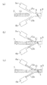
次に、本実施形態の測定デバイス11の溶液導入法を図4を参照しながら説明する。
Next, a solution introduction method of the measuring
図4(a)、(b)および(c)は、本実施形態の測定デバイス11の溶液導入法を模式的に示す図である。
4A, 4B, and 4C are diagrams schematically illustrating a solution introduction method of the
まず、デバイスの流路9の入口8のコネクタに連結するバルブVを閉め、次いで流路9の出口となる空洞8(すなわち出口コネクタ14)に連結されたポンプ32で吸引し、流路9、連通管15aおよび15b、および抵抗槽6aおよび6bのそれぞれの内部の圧力を大気圧P1よりわずかに低い圧力Pdまで減圧する。次いで、バルブVを大気に開放すると、図4(a)に示すように、バルブVに連結されたポンプ31から空洞7(すなわち入口コネクタ13)を介して電解質溶液12が流路9内に注入される。
First, the valve V connected to the connector of the
このとき、連通管15aおよび15bを介して流路9に連絡している抵抗槽6aおよび6b内の圧力もまた大気圧P1より小さい圧力Pdとなっている。従って、流路9に注入された電解質溶液12は、図4(b)に示すように、ウェル19を満たして出口となる空洞8(すなわち出口コネクタ14)に向かうとともに、連通管15aおよび15bを満たす。
At this time, the pressure in the
次いで、電解質溶液12が流路9の出口となる空洞8に達したとき、出口コネクタ14に連結されたポンプ32の吸引を停止する。この後、出口となる空洞8をバルブ操作などによって大気に開放し、流路9内の圧力を大気圧P1に戻す。ここで、抵抗槽6aおよび6b内の圧力がほぼPdのままである。このため、連通管15aおよび15bを満たしていた電解質溶液12は、抵抗槽6aおよび6bに向かって流れ込む。抵抗槽6aおよび6b内の圧力がP1に等しくなったときに、図4(c)に示すように停止する。ここで、電解質溶液12の注入を停止し、入口となる空洞7(すなわち入口コネクタ13)に連結されたバルブVを閉鎖する。
Next, when the
次に、電解質溶液12に生体試料21(本実施形態では細胞)を導入する。本実施形態では、生体試料21の導入の際に、流路9の形状から得られる特性を利用する。
Next, the biological sample 21 (cells in this embodiment) is introduced into the
流路9は、図2に示すように、高さ方向の幅が非常に微細な空間である。このような微細な空間に液体が満たされた状態で、更に後から液体が流入する際には、後から導入された液体が層流となって流れやすいという特性がある。流路9内を流れる液体が層流となって流れると、流れる液体はウェル19の内部に満たされた液体とはほとんど混合せずに、ウェル19の上方を通過する。本実施形態では、電解質溶液12が満たされた流路9内に、バルブVに連結されたポンプ31から空洞7(すなわち入口コネクタ13)を介して生体試料21を含む試料溶液を注入する。このとき、生体試料21をモニターしながら、生体試料21がウェル19の上方に到達したときに、試料溶液の注入を停止する。このことによって、流路9内に層流がなくなり、電解質溶液12の拡散が優勢となって、生体試料21がウェル19内に導入される。
As shown in FIG. 2, the
なお、ここでは、生体試料21の導入について説明しているが、これに限定されず、薬剤などの導入および除去も全く同様に行なうことができる。
Although the introduction of the
最終的に、図5に示すように、流路9、ウェル19、連通管15aおよび15bが電解質溶液12で満たされた状態となる。
Finally, as shown in FIG. 5, the
なお、本実施形態では、電解質溶液12として、生体試料21である細胞の細胞内電位を測定するための細胞外液を用いている。細胞外液としては、20mM〜400mMのNaClを主成分とする生理食塩水、および種々の栄養素、成長因子、抗生物質などを含有する培地などが用いられる。
In the present embodiment, as the
特に、本実施形態の測定デバイス10では、抵抗槽6aおよび6bのそれぞれの体積を、連通管15aおよび15bのそれぞれの体積、またはウェル19の体積に比べてかなり大きくなるように設計されている。このため、抵抗槽6aおよび6bの内部の圧力を適宜調節することによって、気液界面が連通管15aおよび15bの所望の位置に存在するように制御することが容易になる。特に、抵抗槽6aおよび6bのそれぞれの体積は、連通管15aおよび15bのそれぞれの体積の5倍以上であることが好ましい。
In particular, the measuring
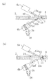
次に、本実施形態の測定デバイス10において、細胞を電極に導く原理の概略を図6を参照しながら説明する。図6(a)および(b)は、細胞を電極に導く原理の概略を示す模式図である。ここでは、測定デバイス10の抵抗槽6bに配置された薄膜抵抗体3bに電流を印加する場合を例示的に説明する。
Next, in the measuring
まず、電流印加部18から薄膜抵抗体3bに電流を印加すると、薄膜抵抗体3bでは、以下の式1で示される電気エネルギーWが消費される。
First, when a current is applied from the
W=RI2 (1)
(ここで、Rは薄膜抵抗体3bの抵抗値[Ω・m]、Iは薄膜抵抗体3bに流れた電流[A]である。)
消費された電気エネルギーWは熱エネルギーとなって、これが、抵抗槽6b内の空気を膨張させる。このことによって、図6(a)に示すように、抵抗槽6b内の圧力をPddにするとともに、これに連通する連通管15bの気液界面の界面張力を減少させる。流路9の出口となる空洞8における気液界面の界面張力は変化していないので、連通管15bにある気液界面と連通管15aにある気液界面との間の界面張力の平衡が崩れ、電解質溶液12は、抵抗槽6bからウェル19に向かって、図6(a)の矢印Bで示される方向(低温の抵抗槽の側)に移動する。生体試料21は、電解質溶液12のこの流れに従って移動し、微小電極1に誘導され、刺入される。
W = RI 2 (1)
(Here, R is the resistance [Ω · m] of the
The consumed electric energy W becomes thermal energy, which expands the air in the
次に、抵抗体6bへの電流供給を停止すると、加熱された抵抗槽6b中の空気の一部は周囲温度に戻り、抵抗槽6b内の圧力はPdd’となる。ここで、再び界面張力が釣り合うようになって、生体試料21は、図6(b)に示すように、移動した位置に保持される。連通管15bの体積は非常に小さく、それに含まれる電解質溶液12の熱容量が小さいので、電解質溶液12の移動は迅速である。
Next, when the current supply to the
本実施形態では、細胞活動測定時に入口となる空洞7および出口となる空洞8を閉じているので、電解質溶液12が連通管15bを移動する距離x(μm)は、連通管15a内にある気液界面の界面張力と、連通管15b内にある気液界面に働く界面張力との差に比例する。従って、薄膜抵抗体3bに印加される電流値Ibおよび電流変化速度ΔIb(A/s)を制御するか、または、薄膜抵抗体3aおよび3bにそれぞれ印加される電流値IaおよびIbの差、および電流変化速度ΔIaおよびΔIbの差を制御することによって、上記の界面張力の差を調節し、連通管15b内の気液界面の移動距離x(μm)およびその移動速度Δx(μm/s)を調節する。
In the present embodiment, since the
ここでは、連通管15b内の気液界面を移動させる場合を説明したが、勿論、連通管15a内の気液界面を移動させる場合も全く同様である。
Here, the case where the gas-liquid interface in the
本実施形態では、細胞に代表される生体試料21の画像をモニターしながら、生体試料21の位置をフィードバック制御する。生体試料21の画像を、透明な基板16を通して撮像部34(例えばCCDなど)によりデジタル変換して計算機35に入力し、生体試料21の移動量などの画像情報を元に、各薄膜抵抗体3aおよび3bに流す電流量を算出する。算出した電流値を自動的に電流印加部18に印加する手段をさらに備えてもよい。勿論、上記の操作を、技術者が手動で全て行なっても構わないが、上記の操作を自動化することによって、より測定を簡単に行なうことが可能である。
In the present embodiment, the position of the
以上に述べたように、本実施形態の測定デバイス10では、薄膜抵抗体3aおよび3bに印加される電流値Ia、Ibおよび電流変化速度ΔIaおよびΔIb(A/s)を制御することによって、抵抗槽6aおよび6b(あるいは連通管15aおよび15b)内にある気液界面に働くそれぞれの界面張力の差を調節し、連通管15aおよび15b内の気液界面の移動距離およびその移動速度を調節する。
As described above, in the
このため、本実施形態の測定デバイス10では、ウェル19内に電解質溶液12の局所的流れを生じさせ、この局所的流れを利用して、生体試料21を微小電極1に正確で且つ迅速に誘導し、生体試料21の電気生理学的測定を行なうことができる。従って、従来のこの種の装置では必要であった高精度な位置制御装置、および熟練した操作も必要としない。
For this reason, in the
また、本実施形態の測定デバイス10は、ウェル19内の細胞21に、神経刺激物質や化学シナプス情報伝達物質などの化学物質を投与することが可能であるため、薬剤の投与による細胞のイオンチャネル特性や化学シナプスを測定する細胞内記録法と同様の高精度の測定を簡便に行なうことができる。
Moreover, since the measuring
特に、本実施形態の測定デバイス10では、連通管15aおよび15bが、流路9(すなわちウェル19)を対称軸としてほぼ線対称に配置されている。このことによって、ウェル19内に生じる電解質溶液12の局所的流れを、連通管15aと連通管15bとの間で双方向(つまり、微小電極1から見て左右方向)に生じさせることが可能である。
In particular, in the
さらに、図3に示すように、連通管15aおよび連通管15bは、連通管15aおよび連通管15bがそれぞれ流路9(すなわちウェル19)に対してなす角度をαとすると、αは必ず鈍角になるように配置されている。このことによって、ウェル19内に生じる電解質溶液12の局所的流れが必ず微小電極1に向かう方向に生じる。
Further, as shown in FIG. 3, the
以上の説明からわかるように、本実施形態の測定デバイス10では、ウェル19内において、電解質溶液12の局所的流れを水平面内で2次元的に生じさせることができる。
As can be seen from the above description, in the
また、本実施形態では、連通管15aおよび15bが流路9(すなわちウェル19)を対称軸としてほぼ線対称に配置されていることによって、連通管15aおよび15b内にある気液界面に働くそれぞれの界面張力の差の計算が非常に単純化される。
Further, in the present embodiment, the
さらに、本実施形態では、抵抗槽6aおよび6bもまた、連通管15aおよび15bと同様に流路9(すなわちウェル19)を対称軸としてほぼ線対称に配置されている。このことによって、抵抗槽6aおよび6b(あるいは連通管15aおよび15b)内にある気液界面に働くそれぞれの界面張力の差の計算がさらに単純化される。このため、上記の界面張力の差を非常に容易に調節することができる。
Furthermore, in the present embodiment, the
さらにまた、本実施形態の測定デバイス10では、基準電極2は、基板16に形成された流路9の入口7の近傍に配置されている。しかしながら、基準電極2は、流路9に電解質溶液12が満たされたときに、電解質溶液12に接触する位置に設けられていればよい。特に、正確な測定を行なうためには、基準電極2を電解質溶液12の局所的流れが生じるウェル19の外部に設けることが好ましい。
Furthermore, in the measuring
次に、本実施形態の測定デバイス10の使用例を説明する。
Next, the usage example of the measuring
(使用例1:電流で刺激された細胞の活動電位の測定)
従来のガラス微小ピペットを用いた細胞内記録法と同様に、本実施形態の測定デバイス10は、電圧固定法および電流固定法によって細胞の発する電気信号を測定することが可能である。
(Usage example 1: measurement of action potential of cells stimulated by electric current)
Similar to the intracellular recording method using a conventional glass micropipette, the measuring
具体的には、上述のように細胞21を微小電極1に誘導して、微小電極1を細胞21に刺入し、基準電極2に対する微小電極1の電位を測定部33において測定する。
Specifically, as described above, the
また、測定部33内に電流パルス発生器を設置しておき、これに微小電極1を接続しておく。そして、端子4aを通じて微小電極1から細胞21に電流刺激を与える。このことによって、電流刺激による細胞の脱分極および一過性の活動電位などを計算機35で計測することができる。
Moreover, the current pulse generator is installed in the
(使用例2:薬剤投与によって刺激された細胞の膜電位測定)
本実施形態の測定デバイス10はまた、細胞のイオンチャネル特性を測定するために用いることができる。これは、入口コネクタ13(空洞7)および出口コネクタ14(空洞8)、ならびにこれらに連結されているポンプ31および32によって、細胞21に、神経刺激物質、化学シナプス伝達物質などの化学物質を投与することにより実施される。
(Use Example 2: Measurement of membrane potential of cells stimulated by drug administration)
The
あるいは、薬剤は、圧電素子を用いたインクジェット法、精密な圧力ポンプまたはマイクロ流体駆動装置を用いた方法、特開平10−337177号公報に開示された方法、エレクトロポレーション法などによっても注入することができる。 Alternatively, the drug may be injected by an ink jet method using a piezoelectric element, a method using a precise pressure pump or a microfluidic drive device, a method disclosed in Japanese Patent Laid-Open No. 10-337177, an electroporation method, or the like. Can do.
例えば、エレクトロポレーション法は、薬剤リザーバーと薬剤注入を注入する標的との間にDCパルスを印加して所望の量を注入する方法である。具体的には、流路9に電解質溶液12を満たし、ウェル19内の電解質溶液12中に細胞21と薬剤とを添加した後、基準電極2と微小電極1との間にDCパルスを印加することによって、所望量の薬剤をウェル19内の細胞21に注入できる。
For example, the electroporation method is a method of injecting a desired amount by applying a DC pulse between a drug reservoir and a target for injecting drug injection. Specifically, the
本実施形態では、微小電極1は、ウェル19の壁面に設けられているが、底面に配置されていてもよい。
In the present embodiment, the
また、本実施形態では、1つの基準電極2に対して、ウェル19内に微小電極1が複数個設けられていてもよい。微小電極1が複数個設けられている場合、複数の微小電極1が1つの端子4aに接続されていてもよいし、複数の微小電極1のそれぞれが、複数の端子に接続されていてもよい。但し、微小電極1が複数個設けられている場合、基準電極2の表面積が、複数の微小電極1の表面積の合計よりも大きいことが好ましい。これは、溶液流れなどの外乱に対する測定の安定性が向上するからである。
In the present embodiment, a plurality of
ウェル19内に微小電極1が複数個設けられている場合、細胞21をそれぞれの微小電極1に固定し、全細胞を同時に測定することも、各細胞を別々に測定することも可能である。特に、生体試料である細胞は必ずしも生きているとは限らない。そこで、本実施形態の測定デバイス10において、ウェル19内に微小電極1が10個設けられている構成であれば、例えば、細胞の生存率が90%である場合、一度の測定で確率的にほぼ9個の細胞のデータが得られる。従って、測定効率の向上にも効果がある。
When a plurality of
本実施形態では、上記コネクタ13および14は、接着剤などによって基板16に接着しているが、これに限定されず、基板16と一体成形されていてもよい。
In the present embodiment, the
基板16および基板17として用いられる材料は、単結晶シリコン、アモルファスシリコン、炭化ケイ素、酸化ケイ素、窒化ケイ素などに代表される半導体材料、SOI(シリコン・オン・インシュレータ)などに代表されるこれら半導体材料の複合素材;ガラス、石英ガラス、アルミナ、サファイア、セラミクス、フォルステライト、感光性ガラスなどの無機材料;ポリエチレン、エチレン、ポリプロビレン、ポリイソブチレン、ポリエチレンテレフタレート、不飽和ポリエステル、含フッ素樹脂、ポリ塩化ビニル、ポリ塩化ビニリデン、ポリ酢酸ビニル、ポリビニルアルコール、ポリビニルアセタール、アクリル樹脂、ポリアクリロニトリル、ポリスチレン、アセタール樹脂、ポリカーボネート、ポリアミド、フェノール樹脂、ユリア樹脂、エポキシ樹脂、メラミン樹脂、スチレン・アクリロニトリル共重合体、アクリロニトリル・ブタジエンスチレン共重合体、ポリフェニレンオキサイドおよびポリスルホンなどの有機材料;ノボラック樹脂をベース樹脂とするノボラック樹脂−ジアゾナフトキノン(DNQ)系感光材料;ポリメチルメタクリレート(PMMA)およびPMMAとの共重合体、ポリメチレンスルホン、ポリヘキサフルオロブチルメタクリレート、ポリメチルイソプロペニルケトン(PMIPK)、ポリジメチルシロキサン(PDMS);および環化ポリイソプレンをベースポリマーとするアジド化合物、例えば、2−6−ジ(4−ジドベザール)−4−メチルシクロヘキサノンなどから構成される感光材料群;を含むがこれらに限定されない。これらの中では、アモルファスシリコン、単結晶シリコン、またはガラスが基板16および基板17として好適に用いられる。
The materials used as the
なお、流路9を構成する基板16の凹部9aおよび基板17のウェル19の表面は、親水性処理が施されていることが好ましい。このことによって、微小な流路9内に液体を流すことができる。
The surface of the
微小電極1および基準電極2は、白金、白金黒、金、パラジウム、ロジウム、銀、水銀、タングステンおよびそれらの化合物などの貴金属材料;およびグラファイト、グラシーカーボン、パイロリティックグラファイト、カ−ボンペ−スト、カ−ボンファイバ−に代表される炭素材料などの電極材料から作製されるが、これらに制限されるわけではない。なお、微小電極1および基準電極2は導電性高分子によって被覆されていてもよい。このことによって安定な固定化電極を作製することができる。また、これらの電極を単分子膜によって被覆することも可能である。
The
薄膜抵抗体3aおよび3bは、白金、白金黒、金、パラジウム、ロジウム、銀、水銀、タングステン、ニッケル、チタンおよびそれらの化合物などの貴金属材料;グラファイト、グラシーカーボン、パイロリティックグラファイト、カ−ボンペ−スト、カ−ボンファイバ−に代表される炭素材料;Si、Ge、ZnO、CdS、TiO2、GaAs、チタンなどの材料から作製され得るが、これらに制限されるわけではない。なお、上記の微小電極1および基準電極2と同様に、薄膜抵抗体3aおよび3bは、導電性高分子によって被覆されてもよく、これによって安定な薄膜抵抗体を作製することができる。また、この抵抗体は、単分子膜によって被覆することもできる。
The
本実施形態では、抵抗槽6aおよび6bは、空気が充填されている。しかしながら、空気に限定されず、電解質溶液12との間で界面張力に変化を生じさせることが可能な気体および液体であれば用いることが可能である。
In this embodiment, the
なお、本実施形態では、薄膜抵抗体3aおよび3bを抵抗槽6aおよび6bに配置しているが、連通管15aおよび15bに配置しても、本実施形態の測定デバイス10を全く同様に動作させることが可能である。また、薄膜抵抗体3aおよび3bは、くし型形状であることが好ましい。このことによって、狭い領域でも第1および第2抵抗体を長さを大きくでき、抵抗値を大きくすることが可能となる。
In the present embodiment, the
また、本実施形態では、ポンプ31および32を用いているが、これに限られず、ポンプ31および32のそれぞれに代えてシリンジを用いてもよい。
Moreover, in this embodiment, although the
(実施形態2)
本実施形態では、上記実施形態1の測定デバイス10において、測定セル11に代えて用いることができる測定セル11’を図を参照しながら説明する。なお、説明の簡素化を図るために、上記実施形態1と共通する構成要素を同一の参照符号で示す。
(Embodiment 2)
In the present embodiment, a
本実施形態の測定セル11’は、外観上は上記実施形態1の測定セル11とほぼ同じである。そこで、本実施形態では、図1に示す測定セル11を、測定セル11’と置き換えて説明する。
The measurement cell 11 'of the present embodiment is substantially the same as the
図7は、図1中に示したIII−III線に沿った断面図である。図8は、図1中に示した矢印Aから見た測定セル11’の透視図である。なお、図8中に示すIII−III線に沿った断面図は、図7の断面図に相当する。また、図8では、測定セル11’のうちの基板16の図示を省略している。
7 is a cross-sectional view taken along line III-III shown in FIG. FIG. 8 is a perspective view of the measurement cell 11 'viewed from the arrow A shown in FIG. Note that the cross-sectional view taken along the line III-III shown in FIG. 8 corresponds to the cross-sectional view of FIG. In FIG. 8, the
測定セル11’は、上記実施形態1の測定セル11とほぼ同じ構造である。但し、図7および図8に示すように、ウェル19(すなわち流路9)に接続された連通管15cと、連通管15cに接続されている抵抗槽6cと、抵抗槽6c内に配置された薄膜抵抗体3cとが設けられている点が異なる。
The
このため、本実施形態の測定セル11’では、ウェル19内において、電解質溶液12の局所的流れを水平面内で前後左右(つまり、2次元的に完全に自由)に生じさせることができる。従って、本実施形態の測定セル11’を用いれば、上記実施形態1の測定セル11を用いるよりも、電解質溶液12内に含まれる生体試料21の位置制御を自由に行なうことができる。
For this reason, in the
さらに、電解質溶液12内に含まれる生体試料21の位置制御の自由度が高くなるので、微小電極1をウェル19内に自由に設けることができる。つまり、ウェル19内の設計の自由度が向上する。
Furthermore, since the degree of freedom in controlling the position of the
本実施形態の測定セル11では、微小電極1に対向してウェル19(すなわち流路9)に接続された連通管15cと、連通管15cに接続されている抵抗槽6cと、抵抗槽6c内にそれぞれ配置された薄膜抵抗体3cとが設けられているので、ウェル19内に生じる電解質溶液12の局所的流れが微小電極1に向かう方向に生じさせることが可能である。
In the
また、図8に示すように、連通管15aおよび連通管15bは、それぞれ流路9(すなわちウェル19)に対してなす角度をαとすると、角度αは必ず鋭角になるように配置されている。つまり、連通管15aに沿って延びる直線と、連通管15bに沿って延びる直線とが微小電極1に向かって開くように、連通管15aおよび連通管15bが配置されている。このことによって、ウェル19内に生じる電解質溶液12の局所的流れが必ず微小電極1から遠ざかる方向に生じさせることが可能である。
Further, as shown in FIG. 8, the
さらに、連通管15aおよび15bが、流路9(すなわちウェル19)を対称軸としてほぼ線対称に配置されている。このため、ウェル19内に生じる電解質溶液12の局所的流れを、連通管15aと連通管15bとの間で双方向(つまり、微小電極1から見て左右方向)に生じさせることが可能である。
Furthermore, the
以上の説明からわかるように、本実施形態の測定セル11’は、図8に示すように、非常に対称性の高い構造を有しているので、抵抗槽6a、6bおよび6c(あるいは連通管15a、15bおよび15c)内にある気液界面に働くそれぞれの界面張力の差の計算が単純化される。このため、上記の界面張力の差を容易に調節することができる。
As can be seen from the above description, the
特に、本実施形態の測定セル11’において、連通管15aおよび連通管15bがそれぞれ流路9(すなわちウェル19)に対してなす角度αは、ほぼ60°であり、連通管15cが微小電極1に対向して設けられていることが好ましい。このことによって、抵抗槽6a、6bおよび6c(あるいは連通管15a、15bおよび15c)内にある気液界面に働くそれぞれの界面張力の差の計算が最も単純化される。このため、上記の界面張力の差を非常に容易に調節することができる。
In particular, in the
なお、本実施形態では、互いに異なる3方向に延びる連通管とそれらに接続された各抵抗槽および各抵抗体を設ける構成としているが、さらに上記3方向とは互いに異なる方向に延びる連通管とそれに接続された抵抗槽および抵抗体とを追加して設けてもよい。このことによって、追加した連通管が延びる方向に、生体物質21を容易に誘導することができる。つまり、生体物質21を容易に誘導することができる方向が増える。このため、生体物質21の微小電極1への誘導をより精密に行なうことが可能になる。
In addition, in this embodiment, it is set as the structure which provides the mutually different communication pipe | tube extended in three directions, and each resistance tank and each resistor connected to them, Furthermore, the communication pipe | tube extended in a mutually different direction from said 3 directions, and it A connected resistance tank and a resistor may be additionally provided. Thereby, the
(実施形態3)
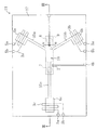
図9は、本実施形態の測定デバイスの構成を示す図である。
(Embodiment 3)
FIG. 9 is a diagram showing the configuration of the measurement device of the present embodiment.
図9に示すように、本実施形態の測定デバイス10’は、上記実施形態1または2の測定デバイス10と同様に、測定セル11または11’を備える。特に、本実施形態の測定デバイス10’では、測定セル11または11’が複数設けられており、複数の測定セル11または11’がマトリクス状に集積化されている。測定セル11または11’の構成は、それぞれ上記実施形態1または実施形態2と全く同じである。
As shown in FIG. 9, the
各測定セル11または11’が備える入口コネクタ13および出口コネクタ14は、バルブおよびポンプを備えた流路切替器38に連結されている。流路切替器38によって、入口コネクタ13を出口として、出口コネクタ14を入口として、交換可能に用いることも可能な構成となっている。
The
さらに、本実施形態の測定デバイス10’では、各流路切替器38に接続された流体駆動装置41aおよび41b、ならびに42aおよび42bが設けられている。流体駆動装置41aおよび41b、ならびに42aおよび42bとしては、例えば、ポンプ、空気圧縮機、シリンジなどが用いられる。
Furthermore, in the
また、本実施形態の測定デバイス10’では、電流印加部18および測定部33は、マルチプレクサ36および37によりそれぞれスイッチング可能であるように構成されている。電流印加部18、測定部33、マルチプレクサ36および37の動作は、電流印加部18および測定部33に接続された計算機35で制御される。
Further, in the
本実施形態の測定デバイス10’によれば、同時に複数の測定を行なうことが可能である。
According to the
(実施形態4)
本実施形態では、上記実施形態1の測定デバイス10を用いて行なう測定方法を図10を参照しながら説明する。図10は、本実施形態の測定方法を表すフローチャートである。
(Embodiment 4)
In the present embodiment, a measurement method performed using the
まず、図10に示すように、ステップSt1において、上記実施形態1で述べた層流を利用する方法でウェル19内に細胞21を導入し、細胞21の位置を制御して微小電極11に固定した後、細胞内電位を測定する。
First, as shown in FIG. 10, in step St1, the
次に、図10に示すように、ステップSt2において、バルブVを切り替えて入口コネクタ13から刺激剤溶液を流路9に注入する。刺激剤溶液がウェル19上に到達したときに、刺激剤溶液の注入を停止し、流路9内の液体の流れを止める。このことによって、刺激剤はウェル19内に拡散し、微小電極11に固定された細胞21が刺激される。
Next, as shown in FIG. 10, in step St <b> 2, the valve V is switched to inject the stimulant solution from the
次に、図10に示すように、ステップSt3において、再度、細胞内電位を測定する。 Next, as shown in FIG. 10, the intracellular potential is measured again in step St3.
次に、図10に示すように、ステップSt4において、ウェル19内を洗浄する。具体的には、バルブVを切り替えて入口コネクタ13から洗浄液を流路9に注入し、洗浄液がウェル19上に到達したときに、洗浄液の注入を停止する。このことによって、洗浄液がウェル19内に拡散する。続いて、洗浄液を出口コネクタ14から排出する。特に本ステップでは、洗浄液の注入および排出の操作を繰り返す。このことによって、ウェル19内が洗浄される。
Next, as shown in FIG. 10, the interior of the well 19 is cleaned in step St4. Specifically, the valve V is switched to inject the cleaning liquid from the
次に、図10に示すように、ステップSt1〜4を、刺激剤溶液における刺激剤の濃度を順次増大させながら繰り返す。このことによって、刺激剤の濃度と細胞内電位との相関関係を調査することができる。 Next, as shown in FIG. 10, steps St1 to St4 are repeated while increasing the concentration of the stimulant in the stimulant solution sequentially. Thereby, the correlation between the concentration of the stimulant and the intracellular potential can be investigated.
また、上記ステップSt2の前に、予め拮抗剤を、刺激剤と同様の手順でウェル19内に導入しておくことによって、拮抗剤と細胞内電位との相関関係を調査することも可能である。 In addition, it is possible to investigate the correlation between the antagonist and the intracellular potential by introducing the antagonist into the well 19 in advance in the same procedure as that of the stimulant before Step St2. .
以下に、本発明の実施例を説明する。以下に述べる実施例は、本発明の例示であり、本発明を制限するものではない。 Examples of the present invention will be described below. The following examples are illustrative of the present invention and are not intended to limit the present invention.
―実施例―
ここでは、上記実施形態1の測定デバイス10を用いて、生体試料として単離細胞を測定する場合の実施例について説明する。
-Example-
Here, the Example in the case of measuring an isolated cell as a biological sample using the
(実施例1)
測定デバイスの製作
基板16の材料として2mm厚のガラス板を用いた。幅60mm×長さ100mmのガラス板の表面に、φ100μmのエンドミルを使い、幅150μm、長さ3mm、深さ70μmの凹部9aを形成した。その後、凹部9aを丹念に研磨した。凹部9aの両端に入口および出口となる直径1.5mmの貫通穴をあけた。
Example 1
A glass plate having a thickness of 2 mm was used as a material for the
基板17の材料として単結晶シリコンウェハを用いた。基板17の表面に、フォトリソグラフィーおよび異方性エッチングを用い、幅150μm、長さ500μm、深さ30μmの逆台形型のウェル19、幅400μm、長さ1000μm、深さ30μmの逆台形型の抵抗槽6aおよび6b、幅10μm、長さ500μm、深さ7.1μmの逆三角柱型の連通管15aおよび15bを形成した。具体的な製作工程は以下に述べるとおりである。
A single crystal silicon wafer was used as the material of the
単結晶シリコンウェハを120℃で20分間ベイクした後、十分脱水し、その表面にフォトレジストを1000rpmで5秒間スピンコートして成膜した。その後、この基板を90℃で10分間プリベイクし、ウェルを露光によりマスクパターンし、専用現像液を用いて現像および洗浄し、ウエットエッチングによりウェル19および抵抗槽6aおよび6bおよび連通管15aおよび15bを完成した。ここでは、24wt%KOH、および界面活性剤であるIPA(イソプロピルアルコール)の混合溶液をエッチャントとして用いた。この混合溶液を、循環ポンプを用いて循環し、そして溶液温度を73℃±3℃に制御した状態で35分エッチングを行った。
The single crystal silicon wafer was baked at 120 ° C. for 20 minutes and then sufficiently dehydrated, and a photoresist was spin coated on the surface at 1000 rpm for 5 seconds to form a film. Thereafter, this substrate is pre-baked at 90 ° C. for 10 minutes, the well is mask-patterned by exposure, developed and washed using a dedicated developer, and the well 19,
微小電極1は、単結晶シリコンを材料とし、円形エッチングマスク直下でアンダーエッチングして作製した。微小電極は、先端が尖った略円錐形状となり、その外周面が凹み方向へ湾曲し、先端近傍径がほぼ1μm、底面部の直径がほぼ16μm、高さほぼ8μmであった。その後、微小電極表面を、タングステンをスパッタにて成膜した後、先端部を残して、ポリイミドで絶縁被覆した。
The
その後、基板17に、薄膜抵抗体3aおよび3b、ならびにその引出し配線、基準電極2およびその引出し配線、ならびに微小電極1からの引出し配線を製作した。簡単に述べれば、基板17に真空蒸着法により0.5μm厚の白金膜を形成した。その後、フォトリソグラフィーによって、白金膜のうち、上記の電極、抵抗体および配線以外の部分を除去した。なお、配線は80μm幅、薄膜抵抗体3aおよび3bは25μm幅を有するくし型形状とした。
Thereafter, the
ここで、基板16と基板17とを陽極接合により接合し、閉じた流路9を形成した。陽極接合は、400〜600℃、600Vの直流電圧を10分間印加する条件で行った。その後、入口コネクタ13および出口コネクタ14を、基板16の凹部9aの両端に形成した貫通穴に接続した。次いで、流路9の出口に接続されたコネクタに、3方コックおよびフィッティングジョイントを介してコンプレッサーを接続した。
Here, the
(実施例2)
神経細胞の活動電位の測定
測定デバイス10の流路9の出口コネクタ14側を、大気圧よりわずかに低い圧力になるように減圧し、入口コネクタ13に連結されたペレスタティックポンプを用い、モノアラガイ用培地(40mM NaCl、1.7mM KCl、4.1mM CaCl2、1.5mM MgCl2、5mM グルコース、5mM HEPES、pH7.9)を、入口コネクタ13から10μl/分〜100μl/分の流速で流路9に注入した。このとき、連通管15aおよび15bを通って抵抗槽6aおよび6b内に培地が入っていくのが観測された。
(Example 2)
Measurement of action potential of nerve cell The
ここで、モノアラガイ用培地が出口コネクタ14まで注入されたことを確認した後、出口コネクタ14側からの減圧操作を止め、三方コックを解放し出口コネクタ14側を大気圧に戻した。このとき、連通管15aおよび15bにはさらに培地が流れ込み、連通管15aおよび15bと抵抗槽6aおよび6bとの接続部位に気液界面が位置するようになった。
Here, after confirming that the medium for monoaragai was injected to the
モノアラガイより摘出した神経節を、1mg/mlのProtease Type14(SIGMA、P−5147)溶液中で37℃25分間振とうし、神経細胞を単離させた。得られたモノアラガイ神経細胞を、モノアラガイ用培地に懸濁し、入口コネクタ13から注意深く流路9に導入した。そして、顕微鏡下で流路9を観察し、モノアラガイ神経細胞がウェル19の上方に到達した瞬間に、入口コネクタ13および出口コネクタ14に連結されたバルブVを閉めたところ、神経細胞がウェル19内に導入されたことを確認した。
The ganglion excised from monoaragai was shaken in a 1 mg / ml Protease Type 14 (SIGMA, P-5147) solution at 37 ° C. for 25 minutes to isolate nerve cells. The obtained monoaraga neurons were suspended in the monoaraga medium and carefully introduced into the
次いで、薄膜抵抗体3aおよび3bに、10mAp−p(ミリアンペア ピーク トウ ピーク)を30秒間印加したところ、神経細胞はウェル19内を移動して微小電極1に突き刺さった。ここで、微小電極1に10nAp−pで1ミリ秒間矩形波電流刺激パルスを印加し、膜電流固定法により細胞内電位を測定した。細胞内電位は、310ミリ秒を1区間として60回分、サンプリング周波数50kHzで記録した。
Next, when 10 mAp-p (milliampere peak toe peak) was applied to the
次に、電流刺激を、8nAp−p、1ミリ秒の矩形波電流刺激を印加することにより測定を行った。3回の測定結果を図11に示す。なお、本実施例の測定は全て、ブリッジバランスを取り、デバイス容量の補正を施した。また、測定データは、5kHz四次バタワース型ローパスフィルタを通した後、計算機に取り込まれようにした。 Next, the current stimulus was measured by applying a square wave current stimulus of 8 nAp-p and 1 millisecond. The results of three measurements are shown in FIG. In all of the measurements of this example, the bridge balance was taken and the device capacity was corrected. In addition, the measurement data was passed through a 5 kHz fourth-order Butterworth low-pass filter and then taken into the computer.
図11に示すように、150ミリ秒から250ミリ秒の間に電流刺激による細胞の電位応答が観測され、従来の細胞内記録法によるものと同様に神経細胞の活動電位が検出されることが示された。 As shown in FIG. 11, the cell potential response due to the current stimulation is observed between 150 milliseconds and 250 milliseconds, and the action potential of the nerve cell is detected as in the conventional intracellular recording method. Indicated.
(実施例3)
生体試料21としてラット動脈由来の平滑筋(SM)を用いた。測定デバイス10内に注入する溶液として、10%FBS(Fetal Bovine Serum)を添加したDMEM培地を使用した。実施例2と同様の操作を行うことによって平滑筋細胞を微小電極1に刺し、アセチルコリンのアナログである、Carbacholを100μMの濃度の溶液として導入したときの、膜電流固定法による細胞内電位を測定した。
(Example 3)
As the
Carbacholを投与したときに計測された自発性の活動電位を測定した結果を図12に示す。図12に示されるように、Carbacholに応答する活動電位が検出された。これは、従来の細胞内記録法によるものと同様の測定結果である。 The results of measuring the spontaneous action potential measured when Carbachol was administered are shown in FIG. As shown in FIG. 12, an action potential in response to Carbachol was detected. This is the same measurement result as that obtained by the conventional intracellular recording method.
さらに、図13に、細胞内記録法によるデータに、信号処理を加えたときの10ミリ秒毎の標準偏差値のヒストグラムを示す。図13はCarbachol投与前後の10ミリ秒毎の標準偏差値のヒストグラムである。Carbachol投与前後のヒストグラムを正規分布により近似して求めたグラフの平均値および半値幅は、投与前では0.185および0.04、投与後では0.545および0.21であり、Carbachol投与前後で、10ミリ秒毎の偏差値の平均値が増加していることがわかる。これはCarbacholを投与することによって、モノアラガイ神経細胞のイオンチャンネルが活性化され、その活性化されたチャンネルの開閉によるコンダクタンスの変動が電圧変化として表されているためである。図13から、測定デバイス10は、従来の細胞内記録法によるものと同様に、神経刺激物質に対するイオンチャネル特性が決定できることがわかった。
Further, FIG. 13 shows a histogram of standard deviation values every 10 milliseconds when signal processing is added to the data by the intracellular recording method. FIG. 13 is a histogram of standard deviation values every 10 milliseconds before and after Carbachol administration. The mean and half-value widths of the graph obtained by approximating the histogram before and after Carbachol administration by normal distribution were 0.185 and 0.04 before administration, 0.545 and 0.21 after administration, and before and after Carbachol administration It can be seen that the average value of deviation values every 10 milliseconds is increased. This is because administration of Carbachol activates the ion channel of monoaragai neurons, and the change in conductance due to the opening and closing of the activated channel is expressed as a voltage change. From FIG. 13, it was found that the
このように、測定デバイス10では、従来の細胞内記録を行わなずに、イオンチャンネル活性度抽出方法により、簡便にチャンネルの開閉に伴う細胞活動を測定することができる。従って、測定デバイス10を用いて、細胞への薬物投与の前後またはその投与量に対するチャンネル活性度の絶対値やチャンネル活性度の増減を比較することによって、細胞チャンネル活性度の測定や、薬物の作用効果の定性的または定量的な分類を行うことが可能となる。
As described above, the measuring
以上に述べた実施例2および3の結果から、測定デバイス10は、微小電極1に誘導された細胞21から、細胞膜電位および一過性の活動電位を微小電極1によって高感度に取得することが可能であることがわかる。
From the results of Examples 2 and 3 described above, the
以上に説明したように、本発明によれば、簡易で、正確、高速かつ自動的に、生体試料の電気生理学的評価を行なうことが可能な測定デバイスが提供される。 As described above, according to the present invention, a measurement device capable of performing electrophysiological evaluation of a biological sample in a simple, accurate, high-speed and automatic manner is provided.
本発明の測定デバイスおよび測定方法は、薬品スクリーニング等に代表される生体試料の電気生理学的評価を行なうために利用される。 The measurement device and the measurement method of the present invention are used to perform electrophysiological evaluation of a biological sample represented by drug screening and the like.
Claims (18)
第1の方向に延びる流路と、
上記流路の両端に連結された1対の導入口と、
上記流路内に設けられた凹形状のウェルと、
上記流路内に設けられた基準電極と、
上記ウェル内に設けられた少なくとも1つの微小電極と、
上記ウェルに連結されており、上記第1の方向と異なる第2の方向に延びる第1連通管と、
上記ウェルのうちの、上記第1連通管と異なる部分に連結されており、上記第1の方向および第2の方向のいずれとも異なる第3の方向に延びる第2連通管と、
上記第1および第2連通管のそれぞれに接続された第1および第2抵抗槽と、
上記第1および第2連通管または上記第1および第2抵抗槽に配置された第1および第2抵抗体とを備える測定デバイス。 A measuring device for measuring an electrical signal emitted from a biological sample,
A flow path extending in a first direction;
A pair of inlets connected to both ends of the flow path;
A concave well provided in the flow path;
A reference electrode provided in the flow path;
At least one microelectrode provided in the well;
A first communication pipe connected to the well and extending in a second direction different from the first direction;
A second communication pipe connected to a portion of the well different from the first communication pipe and extending in a third direction different from both the first direction and the second direction;
First and second resistance vessels connected to each of the first and second communication pipes;
A measuring device comprising the first and second communicating pipes or the first and second resistors arranged in the first and second resistance tanks.
上記第1連通管と上記第2連通管とは、上記流路を対称軸として線対称に配置されていることを特徴とする測定デバイス。 The measuring device according to claim 1,
The measurement device, wherein the first communication pipe and the second communication pipe are arranged symmetrically with respect to the flow path as an axis of symmetry.
上記第1連通管および上記第2連通管は、上記第1連通管に沿って延びる直線と、上記第2連通管に沿って延びる直線とが上記少なくとも1つの微小電極に向かって交差するように配置されていることを特徴とする測定デバイス。 The measuring device according to claim 1,
The first communication pipe and the second communication pipe are arranged such that a straight line extending along the first communication pipe and a straight line extending along the second communication pipe cross toward the at least one microelectrode. A measuring device characterized in that it is arranged.
上記少なくとも1つの微小電極は、突起状の先端部を有することを特徴とする測定デバイス。 The measuring device according to claim 1,
The measurement device, wherein the at least one microelectrode has a protruding tip.
上記少なくとも1つの微小電極は、複数の微小電極であることを特徴とする測定デバイス。 The measuring device according to claim 1,
The measurement device, wherein the at least one microelectrode is a plurality of microelectrodes.
上記基準電極の表面積は、上記複数の微小電極の表面積の合計よりも大きいことを特徴とする測定デバイス。 The measuring device according to claim 5, wherein
The measuring device, wherein a surface area of the reference electrode is larger than a total surface area of the plurality of microelectrodes.
第1基板と、上記第1基板上に設けられた第2基板とをさらに備え、
上記第1基板は、上記ウェルと、上記基準電極と、上記微小電極と、上記第1および第2連通管と、第1および第2抵抗槽と、第1および第2抵抗体とを有し、
上記第2基板は、上記第1基板上に設けられた状態で上記流路となる、上記第1の方向に延びる凹部と、上記第1基板上に設けられた状態で上記1対の導入口となる、上記凹部の両端に形成された空洞とを有することを特徴とする測定デバイス。 The measuring device according to claim 1,
A first substrate; and a second substrate provided on the first substrate;
The first substrate includes the well, the reference electrode, the microelectrode, the first and second communication pipes, first and second resistance vessels, and first and second resistors. ,
The second substrate has a recess extending in the first direction, which serves as the flow path when provided on the first substrate, and the pair of inlets provided on the first substrate. And a cavity formed at both ends of the recess.
上記第2基板は、透明の材料から形成されていることを特徴とする測定デバイス。 The measuring device according to claim 7,
The measurement device, wherein the second substrate is made of a transparent material.
上記第1基板は、半導体材料から形成されていることを特徴とする測定デバイス。 The measuring device according to claim 7,
The measurement device, wherein the first substrate is made of a semiconductor material.
上記第1連通管の体積は、上記第1抵抗槽の体積の1/5未満であり、
上記第2連通管の体積は、上記第2抵抗槽の体積の1/5未満であることを特徴とする測定デバイス。 The measuring device according to claim 1,
The volume of the first communication pipe is less than 1/5 of the volume of the first resistance tank,
The volume of the said 2nd communicating pipe is less than 1/5 of the volume of the said 2nd resistance tank, The measuring device characterized by the above-mentioned.
上記流路の表面は、親水性処理が施されていることを特徴とする測定デバイス。 The measuring device according to claim 1,
A measuring device, wherein a surface of the flow path is subjected to a hydrophilic treatment.
上記第1および第2抵抗体は、くし型形状であることを特徴とする測定デバイス。 The measuring device according to claim 1,
The measuring device, wherein the first and second resistors are comb-shaped.
上記ウェルのうちの、上記第1および第2連通管と異なる部分に連結されており、上記第2の方向および上記第3の方向のいずれとも異なる第4の方向に延びる第3連通管と、
上記第3連通管に接続された第3抵抗槽と、
上記第3連通管または上記第3抵抗槽に配置された第3抵抗体とをさらに備えることを特徴とする測定デバイス。 The measuring device according to claim 3,
A third communication pipe connected to a portion of the well different from the first and second communication pipes and extending in a fourth direction different from both the second direction and the third direction;
A third resistance tank connected to the third communication pipe;
A measuring device further comprising: a third resistor disposed in the third communication pipe or the third resistance tank.
上記第1連通管および上記第2連通管は、上記第1連通管に沿って延びる直線と、上記第2連通管に沿って延びる直線とが上記少なくとも1つの微小電極に向かって開くように配置されており、
上記第3連通管は、上記少なくとも1つの微小電極の先端部が上記第3連通管に沿って延びる直線上に実質的に位置するように配置されていることを特徴とする測定デバイス。 The measuring device according to claim 13,
The first communication pipe and the second communication pipe are arranged so that a straight line extending along the first communication pipe and a straight line extending along the second communication pipe open toward the at least one microelectrode. Has been
The measurement device, wherein the third communication pipe is arranged so that a tip portion of the at least one microelectrode is substantially located on a straight line extending along the third communication pipe.
上記第1の方向に延びるもう1つの流路と、
上記もう1つの流路の両端に連結されたもう1対の導入口と、
上記もう1つの流路内に設けられた凹形状のもう1つのウェルと、
上記もう1つの流路内に設けられたもう1つの基準電極と、
上記もう1つのウェル内に設けられた少なくとも1つのもう1つの微小電極と、
上記もう1つのウェルに連結されており、上記第1の方向と異なる第2の方向に延びるもう1つの第1連通管と、
上記もう1つのウェルのうちの、上記もう1つの第1連通管と異なる部分に連結されており、上記第1の方向および第2の方向のいずれとも異なる第3の方向に延びるもう1つの第2連通管と、
上記もう1つの第1および第2連通管のそれぞれに接続されたもう1つの第1および第2抵抗槽と、
上記もう1つの第1および第2連通管または上記もう1つの第1および第2抵抗槽に配置されたもう1つの第1および第2抵抗体とをさらに備えることを特徴とする測定デバイス。 The measuring device according to claim 1,
Another flow path extending in the first direction;
Another pair of inlets connected to both ends of the other channel;
Another well having a concave shape provided in the other flow path;
Another reference electrode provided in the other flow path;
At least one other microelectrode provided in the other well;
Another first communication pipe connected to the other well and extending in a second direction different from the first direction;
The other well is connected to a portion different from the other first communication pipe and extends in a third direction different from both the first direction and the second direction. Two communicating pipes,
Another first and second resistance tank connected to each of the other first and second communication pipes;
The measuring device further comprising the other first and second communicating pipes or the other first and second resistors disposed in the other first and second resistance tanks.
第1の方向に延びる流路と、上記流路の両端に連結された1対の導入口と、上記流路内に設けられた凹形状のウェルと、上記流路内に設けられた基準電極と、上記ウェル内に設けられた少なくとも1つの微小電極と、上記ウェルに連結されており、上記第1の方向と異なる第2の方向に延びる第1連通管と、上記ウェルのうちの、上記第1連通管と異なる部分に連結されており、上記第1の方向および第2の方向のいずれとも異なる第3の方向に延びる第2連通管と、上記第1および第2連通管のそれぞれに接続された第1および第2抵抗槽と、上記第1および第2連通管または上記第1および第2抵抗槽に配置された第1および第2抵抗体とを備える測定デバイスを用意する工程(a)と、
上記流路内の圧力を低減することによって上記流路に電解質溶液を導入して充填する工程(b)と、
上記流路内の圧力を大気圧に戻す工程(c)と、
上記ウェル内に生体試料を配置する工程(d)と、
上記流路を密閉する工程(e)と、
上記第1抵抗体または第2抵抗体に電流を印加することによって、上記少なくとも1つの微小電極に上記生体試料を接触させる工程(f)と、
上記生体試料が発する電気信号の変化を測定する工程(g)と、
を含む測定方法。 A measurement method for measuring an electrical signal emitted from a biological sample,
A channel extending in the first direction, a pair of inlets connected to both ends of the channel, a concave well provided in the channel, and a reference electrode provided in the channel At least one microelectrode provided in the well; a first communication pipe connected to the well and extending in a second direction different from the first direction; The second communication pipe is connected to a portion different from the first communication pipe and extends in a third direction different from both the first direction and the second direction, and the first communication pipe and the second communication pipe, respectively. A step of preparing a measuring device including the connected first and second resistance vessels and the first and second resistance tubes disposed in the first and second communication tubes or the first and second resistance vessels ( a) and
A step (b) of introducing and filling an electrolyte solution into the flow path by reducing the pressure in the flow path;
A step (c) of returning the pressure in the flow path to atmospheric pressure;
Placing a biological sample in the well (d),
A step (e) of sealing the flow path;
Contacting the biological sample with the at least one microelectrode by applying an electric current to the first resistor or the second resistor; and
Measuring the change in the electrical signal emitted by the biological sample (g);
Measuring method including
上記工程(f)の後に、上記少なくとも1つの微小電極に電気パルスを印加する工程(h)をさらに含むことを特徴とする測定方法。 The measurement method according to claim 16, wherein
The measurement method further comprising a step (h) of applying an electric pulse to the at least one microelectrode after the step (f).
上記1対の導入口のいずれか一方から薬剤を投入する工程(i)をさらに含むことを特徴とする測定方法。 The measurement method according to claim 16 or 17,
The measurement method further comprising a step (i) of introducing a drug from any one of the pair of introduction ports.
Applications Claiming Priority (3)
| Application Number | Priority Date | Filing Date | Title |
|---|---|---|---|
| JP2001353829 | 2001-11-19 | ||
| JP2001353829 | 2001-11-19 | ||
| PCT/JP2002/012085 WO2003044512A1 (en) | 2001-11-19 | 2002-11-19 | Measurement device for measuring electric signal emitted by biological sample |
Publications (2)
| Publication Number | Publication Date |
|---|---|
| JPWO2003044512A1 JPWO2003044512A1 (en) | 2005-03-24 |
| JP3893381B2 true JP3893381B2 (en) | 2007-03-14 |
Family
ID=19165777
Family Applications (1)
| Application Number | Title | Priority Date | Filing Date |
|---|---|---|---|
| JP2003546094A Expired - Lifetime JP3893381B2 (en) | 2001-11-19 | 2002-11-19 | Measuring device and measuring method for measuring an electrical signal emitted from a biological sample |
Country Status (8)
| Country | Link |
|---|---|
| EP (1) | EP1460415B1 (en) |
| JP (1) | JP3893381B2 (en) |
| CN (1) | CN1292249C (en) |
| AT (1) | ATE495437T1 (en) |
| AU (1) | AU2002366139A1 (en) |
| DE (1) | DE60238943D1 (en) |
| DK (1) | DK1460415T3 (en) |
| WO (1) | WO2003044512A1 (en) |
Families Citing this family (9)
| Publication number | Priority date | Publication date | Assignee | Title |
|---|---|---|---|---|
| US7344679B2 (en) * | 2005-10-14 | 2008-03-18 | International Business Machines Corporation | Method and apparatus for point of care osmolarity testing |
| US20090321356A1 (en) * | 2006-03-24 | 2009-12-31 | Waters Investments Limited | Ceramic-based chromatography apparatus and methods for making same |
| JP5551355B2 (en) * | 2008-12-04 | 2014-07-16 | 川崎重工業株式会社 | Cell coupling module, cell coupling device, and cell coupling method |
| CA2758617C (en) * | 2009-04-20 | 2017-10-03 | Oxford Nanopore Technologies Limited | Lipid bilayer sensor array |
| CN105149023B (en) * | 2010-06-30 | 2018-06-12 | 安派科生物医学科技有限公司 | disease detection instrument |
| KR102122313B1 (en) * | 2013-08-12 | 2020-06-12 | 엘지전자 주식회사 | Biosensor capable of recognizing location of fluid and method of recognizing location of fluid using the same |
| CN107271493A (en) * | 2017-07-07 | 2017-10-20 | 中国电建集团中南勘测设计研究院有限公司 | A kind of Air Concentration in Water Flow computational methods and system based on normal distribution |
| DE102018132120B4 (en) * | 2018-12-13 | 2024-04-18 | Fraunhofer-Gesellschaft zur Förderung der angewandten Forschung e.V. | Sample collection device for biological samples with a sample holder made of carbon-based material |
| WO2020162031A1 (en) * | 2019-02-08 | 2020-08-13 | パナソニックIpマネジメント株式会社 | Cellular potential measurement substrate, method for producing same, and cell culture substrate |
Family Cites Families (6)
| Publication number | Priority date | Publication date | Assignee | Title |
|---|---|---|---|---|
| US5639423A (en) * | 1992-08-31 | 1997-06-17 | The Regents Of The University Of Calfornia | Microfabricated reactor |
| JPH09211010A (en) * | 1996-02-06 | 1997-08-15 | Bunshi Bio Photonics Kenkyusho:Kk | Electrophyiological characteristic measuring device |
| JPH09289886A (en) * | 1996-04-25 | 1997-11-11 | Shimadzu Corp | Device for detecting cell membrane potential |
| JPH11299496A (en) * | 1998-04-24 | 1999-11-02 | Hitachi Ltd | Vessel for oocyte and measuring device using the same |
| DE19948473A1 (en) * | 1999-10-08 | 2001-04-12 | Nmi Univ Tuebingen | Method and device for measuring cells in a liquid environment |
| JP3525837B2 (en) * | 1999-12-24 | 2004-05-10 | 株式会社日立製作所 | Automatic electrophysiological measuring device and automatic electrophysiological measuring method |
-
2002
- 2002-11-19 EP EP02803538A patent/EP1460415B1/en not_active Expired - Lifetime
- 2002-11-19 DE DE60238943T patent/DE60238943D1/en not_active Expired - Lifetime
- 2002-11-19 JP JP2003546094A patent/JP3893381B2/en not_active Expired - Lifetime
- 2002-11-19 AT AT02803538T patent/ATE495437T1/en not_active IP Right Cessation
- 2002-11-19 CN CN02822943.6A patent/CN1292249C/en not_active Expired - Lifetime
- 2002-11-19 DK DK02803538.4T patent/DK1460415T3/en active
- 2002-11-19 WO PCT/JP2002/012085 patent/WO2003044512A1/en active Application Filing
- 2002-11-19 AU AU2002366139A patent/AU2002366139A1/en not_active Abandoned
Also Published As
| Publication number | Publication date |
|---|---|
| ATE495437T1 (en) | 2011-01-15 |
| DK1460415T3 (en) | 2011-04-26 |
| CN1292249C (en) | 2006-12-27 |
| EP1460415A4 (en) | 2010-03-10 |
| JPWO2003044512A1 (en) | 2005-03-24 |
| EP1460415A1 (en) | 2004-09-22 |
| EP1460415B1 (en) | 2011-01-12 |
| WO2003044512A1 (en) | 2003-05-30 |
| CN1589399A (en) | 2005-03-02 |
| DE60238943D1 (en) | 2011-02-24 |
| AU2002366139A1 (en) | 2003-06-10 |
Similar Documents
| Publication | Publication Date | Title |
|---|---|---|
| JP4033768B2 (en) | Electrophysiological measurement system | |
| Metz et al. | Flexible polyimide probes with microelectrodes and embedded microfluidic channels for simultaneous drug delivery and multi-channel monitoring of bioelectric activity | |
| US6699697B2 (en) | Planar patch clamp electrodes | |
| Zhao et al. | Patch clamp technique: review of the current state of the art and potential contributions from nanoengineering | |
| US20060228771A1 (en) | Apparatus for and method of making electrical measurements on objects | |
| US6932893B2 (en) | System for electrophysiological measurements | |
| AU780157B2 (en) | A substrate and a method for determining and/or monitoring electrophysiological properties of ion channels | |
| US20030104512A1 (en) | Biosensors for single cell and multi cell analysis | |
| US7718409B2 (en) | Controlled electroporation and mass transfer across cell membranes | |
| JP2003527581A (en) | Apparatus and method for electrical measurement of an object | |
| JP2003511699A (en) | Method and apparatus for measuring cells in a liquid environment | |
| US7462324B2 (en) | Measurement device and method for measuring electric signal from biological sample | |
| US7736477B2 (en) | Probe for measuring electric potential of cell | |
| US20040055901A1 (en) | Substrate and a method for determining and/or monitoring electrophysiological properties of ion channels | |
| TW200422611A (en) | Electrical analysis of biological membranes | |
| US9201058B2 (en) | Apparatus and method for sensing a time varying ionic current in an electrolytic system | |
| AU2001293676A1 (en) | System for electrophysiological measurements | |
| US20120019270A1 (en) | Microfabricated pipette and method of manufacture | |
| JP3893381B2 (en) | Measuring device and measuring method for measuring an electrical signal emitted from a biological sample | |
| US20050009171A1 (en) | Device and method for analyzing ion channels in membranes | |
| US20050212095A1 (en) | Substrate and method for measuring the electrophysiological properties of cell membranes | |
| US20040168912A1 (en) | Planar patch clamp electrodes | |
| Py et al. | Priming and testing silicon patch-clamp neurochips | |
| JP4816111B2 (en) | Micropipette and cell measurement system using the same | |
| US20040020773A1 (en) | Apparatus and method for determining and/or monitoring electrophysiological properties of ion channels |
Legal Events
| Date | Code | Title | Description |
|---|---|---|---|
| TRDD | Decision of grant or rejection written | ||
| A01 | Written decision to grant a patent or to grant a registration (utility model) |
Free format text: JAPANESE INTERMEDIATE CODE: A01 Effective date: 20061128 |
|
| A61 | First payment of annual fees (during grant procedure) |
Free format text: JAPANESE INTERMEDIATE CODE: A61 Effective date: 20061211 |
|
| R150 | Certificate of patent or registration of utility model |
Free format text: JAPANESE INTERMEDIATE CODE: R150 Ref document number: 3893381 Country of ref document: JP Free format text: JAPANESE INTERMEDIATE CODE: R150 |
|
| FPAY | Renewal fee payment (event date is renewal date of database) |
Free format text: PAYMENT UNTIL: 20091215 Year of fee payment: 3 |
|
| FPAY | Renewal fee payment (event date is renewal date of database) |
Free format text: PAYMENT UNTIL: 20101215 Year of fee payment: 4 |
|
| FPAY | Renewal fee payment (event date is renewal date of database) |
Free format text: PAYMENT UNTIL: 20101215 Year of fee payment: 4 |
|
| FPAY | Renewal fee payment (event date is renewal date of database) |
Free format text: PAYMENT UNTIL: 20111215 Year of fee payment: 5 |
|
| FPAY | Renewal fee payment (event date is renewal date of database) |
Free format text: PAYMENT UNTIL: 20111215 Year of fee payment: 5 |
|
| FPAY | Renewal fee payment (event date is renewal date of database) |
Free format text: PAYMENT UNTIL: 20121215 Year of fee payment: 6 |
|
| FPAY | Renewal fee payment (event date is renewal date of database) |
Free format text: PAYMENT UNTIL: 20121215 Year of fee payment: 6 |
|
| FPAY | Renewal fee payment (event date is renewal date of database) |
Free format text: PAYMENT UNTIL: 20131215 Year of fee payment: 7 |
|
| EXPY | Cancellation because of completion of term |