JP3890132B2 - Network server and image processing method - Google Patents
Network server and image processing method Download PDFInfo
- Publication number
- JP3890132B2 JP3890132B2 JP00653398A JP653398A JP3890132B2 JP 3890132 B2 JP3890132 B2 JP 3890132B2 JP 00653398 A JP00653398 A JP 00653398A JP 653398 A JP653398 A JP 653398A JP 3890132 B2 JP3890132 B2 JP 3890132B2
- Authority
- JP
- Japan
- Prior art keywords
- profile
- network
- calibration
- printer
- network server
- Prior art date
- Legal status (The legal status is an assumption and is not a legal conclusion. Google has not performed a legal analysis and makes no representation as to the accuracy of the status listed.)
- Expired - Fee Related
Links
Images


Classifications
-
- H—ELECTRICITY
- H04—ELECTRIC COMMUNICATION TECHNIQUE
- H04N—PICTORIAL COMMUNICATION, e.g. TELEVISION
- H04N1/00—Scanning, transmission or reproduction of documents or the like, e.g. facsimile transmission; Details thereof
- H04N1/32—Circuits or arrangements for control or supervision between transmitter and receiver or between image input and image output device, e.g. between a still-image camera and its memory or between a still-image camera and a printer device
- H04N1/32502—Circuits or arrangements for control or supervision between transmitter and receiver or between image input and image output device, e.g. between a still-image camera and its memory or between a still-image camera and a printer device in systems having a plurality of input or output devices
- H04N1/32523—Circuits or arrangements for control or supervision between transmitter and receiver or between image input and image output device, e.g. between a still-image camera and its memory or between a still-image camera and a printer device in systems having a plurality of input or output devices a plurality of output devices
- H04N1/32529—Circuits or arrangements for control or supervision between transmitter and receiver or between image input and image output device, e.g. between a still-image camera and its memory or between a still-image camera and a printer device in systems having a plurality of input or output devices a plurality of output devices of different type, e.g. internal and external devices
-
- H—ELECTRICITY
- H04—ELECTRIC COMMUNICATION TECHNIQUE
- H04L—TRANSMISSION OF DIGITAL INFORMATION, e.g. TELEGRAPHIC COMMUNICATION
- H04L67/00—Network arrangements or protocols for supporting network services or applications
- H04L67/2866—Architectures; Arrangements
- H04L67/30—Profiles
- H04L67/303—Terminal profiles
-
- H—ELECTRICITY
- H04—ELECTRIC COMMUNICATION TECHNIQUE
- H04N—PICTORIAL COMMUNICATION, e.g. TELEVISION
- H04N1/00—Scanning, transmission or reproduction of documents or the like, e.g. facsimile transmission; Details thereof
- H04N1/32—Circuits or arrangements for control or supervision between transmitter and receiver or between image input and image output device, e.g. between a still-image camera and its memory or between a still-image camera and a printer device
- H04N1/333—Mode signalling or mode changing; Handshaking therefor
- H04N1/33307—Mode signalling or mode changing; Handshaking therefor prior to start of transmission, input or output of the picture signal only
-
- H—ELECTRICITY
- H04—ELECTRIC COMMUNICATION TECHNIQUE
- H04N—PICTORIAL COMMUNICATION, e.g. TELEVISION
- H04N1/00—Scanning, transmission or reproduction of documents or the like, e.g. facsimile transmission; Details thereof
- H04N1/32—Circuits or arrangements for control or supervision between transmitter and receiver or between image input and image output device, e.g. between a still-image camera and its memory or between a still-image camera and a printer device
- H04N1/333—Mode signalling or mode changing; Handshaking therefor
- H04N1/33369—Storage of mode or retrieval of prestored mode
-
- H—ELECTRICITY
- H04—ELECTRIC COMMUNICATION TECHNIQUE
- H04N—PICTORIAL COMMUNICATION, e.g. TELEVISION
- H04N1/00—Scanning, transmission or reproduction of documents or the like, e.g. facsimile transmission; Details thereof
- H04N1/46—Colour picture communication systems
- H04N1/56—Processing of colour picture signals
- H04N1/60—Colour correction or control
- H04N1/603—Colour correction or control controlled by characteristics of the picture signal generator or the picture reproducer
-
- H—ELECTRICITY
- H04—ELECTRIC COMMUNICATION TECHNIQUE
- H04N—PICTORIAL COMMUNICATION, e.g. TELEVISION
- H04N2201/00—Indexing scheme relating to scanning, transmission or reproduction of documents or the like, and to details thereof
- H04N2201/0077—Types of the still picture apparatus
- H04N2201/0082—Image hardcopy reproducer
-
- H—ELECTRICITY
- H04—ELECTRIC COMMUNICATION TECHNIQUE
- H04N—PICTORIAL COMMUNICATION, e.g. TELEVISION
- H04N2201/00—Indexing scheme relating to scanning, transmission or reproduction of documents or the like, and to details thereof
- H04N2201/32—Circuits or arrangements for control or supervision between transmitter and receiver or between image input and image output device, e.g. between a still-image camera and its memory or between a still-image camera and a printer device
- H04N2201/333—Mode signalling or mode changing; Handshaking therefor
- H04N2201/33307—Mode signalling or mode changing; Handshaking therefor of a particular mode
- H04N2201/33314—Mode signalling or mode changing; Handshaking therefor of a particular mode of reading or reproducing mode
Abstract
Description
【0001】
【発明の属する技術分野】
本発明はネットワーク端末とネットワークを介して通信するネットワークサーバに関する。
【0002】
【従来の技術】
特開平07-222-009に記載されているように、カラーマネージメントシステムは、CMM(Color Management Module)とデバイスプロファイルで構成され、変換前のソースデバイスに対応したプロファイルと変換後のデスティネーションデバイスに対応したプロファイルを用いて、入出力画像のカラーマッチングを行うべく色変換処理を行う。
【0003】
前者のプロファイルをソースプロファイル、後者のプロファイルをデスティネーションデバイスプロファイルと呼ぶ。
【0004】
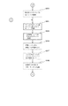
例えば、図1に示す色変換処理では、スキャナ色空間(スキャナRGB)またはモニタ色空間(モニタRGB)からプリンタ色空間(プリンタCMYK)へ変換する処理を行う。
【0005】
この場合、ソースデバイスはスキャナまたはモニタであり、そのスキャナまたはモニタのプロファイルがソースプロファイルになり、デスティネーションデバイスはプリンタであり、そのプリンタのプロファイルがデスティネーションプロファイルになる。
【0006】
図2は、デバイスプロファイルの構造の一例を示している。
【0007】
ここで、プロファイルは、ヘッダー部とデータ格納部に分けられ、ヘッダー部には、そのプロファイルがどのデバイス(例.モニタ)のものであるかを示すデバイス情報、そのプロファイルがどのCMMで使用されるかを示すCMM情報等のプロファイルを管理するために用いられる情報が格納されている。データ格納部にはそのプロファイルを識別するためのプロファイル記述情報が格納されている。このプロファイル記述情報には、例えばメーカー名と製品名を示す情報が格納される。
【0008】
【発明が解決しようとする課題】
従来、上記のようなカラーマネージメントシステムは、ネットワークシステム上では実現されていなかった。即ち、色変換処理に用いるデバイスプロファイルやカラーマネージメントモジュールの送受信間での受け渡しをシステム的に行うことができなかった。
【0009】
そのため、ネットワーク上で送信側と受信側のカラーマッチングを実現することが難しいという欠点があった。
【0010】
本発明は上述した従来例の欠点に鑑みてなされたものであり、ネットワークシステム上でカラーマッチングを実現できるようにすることを目的とする。
【0011】
また、常に高品質の出力画像を得られるようにデバイスプロファイルをキャリブレートできる使い勝手が良い画像処理方法を提供することを目的とする。
【0012】
【課題を解決するための手段】
上記目的を達成するために本発明は、ネットワークを介してネットワーク端末と通信を行うネットワークサーバであって、カラーマッチング処理を実行するためのカラーマネージメントモジュールとデバイスプロファイルの選択情報をネットワーク端末から受け取る手段と、前記選択情報に基づいてカラーマネージメントモジュールとデバイスプロファイルを獲得する獲得手段と、前記獲得されたデバイスプロファイルを前記獲得されたカラーマネージメントモジュールにセットして入力データに対してカラーマッチング処理を行う手段と、前記カラーマッチング処理したデータを前記ネットワーク端末に通信する手段とを有することを特徴とする。
【0013】
また、本発明は複数のキャリブレーション方法を有する画像処理方法であって、前記複数のキャリブレーション方法から任意のキャリブレーション方法を選択し、前記選択されたキャリブレーション方法を用いてカラーマッチング処理に用いるICCプロファイルの仕様に則し、デバイスコネクションスペースからプリンタ色空間への変換を行う3次元LUTと1次元LUTを有するデバイスプロファイルの前記1次元LUTをキャリブレートし、前記キャリブレートされたデバイスプロファイルを格納することを特徴とする。
【0014】
【発明の実施の形態】
(実施形態1)
以下に、添付図面を参照して本発明の好適な実施形態の1例を詳細に説明する。
【0015】
図3は本発明の一実施形態によるネットワークシステムの構成を示す図である。
【0016】
図3のように、本実施形態によるネットワークシステムは、ネットワーク端末1とネットワークサーバー3とネットワークプリンタ4及び前記3つのデバイスが接続されるネットワーク2から構成されている。
【0017】
ネットワーク端末1は、モニタ表示や画像処理に必要なCPU・VRAM等及びネットワーク上の通信に必要な通信機能を備え、モニタの識別のためのモニタ記述情報格納部11とネットワークプリンタ4の識別のためのモニタ記述情報格納部11を有している。
【0018】
ネットワークサーバー3は、画像処理や印刷処理に必要なCPU・RAM・ハードディスク等及びネットワーク上の通信に必要な通信機能を備え、n個(nは定数)のCMMが登録されているCMM格納部31とm個(mは定数)のデバイスプロファイル(モニタ・スキャナ・プリンタ)が格納されているプロファイル格納部32を有している。CMM格納部31に登録されているCMMはそれぞれ識別のための登録情報(例.4バイトの英数字でUCCM)を有している。
【0019】
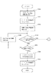
図4〜6は、ネットワーク端末1において文書を表示する際に、文書中に画像ファイルが存在する場合にネットワーク端末1のモニタの特性に合わせて画像ファイル中の画像データに対してネットワークサーバー3がカラーマッチング処理を施してネットワーク端末1のモニタに表示する場合の処理のフロチャートを示している。
【0020】
ステップS100で、表示する文書中に画像ファイルがあるかどうかチェックする。ここで、画像ファイルがない場合にはステップS101に進んで文書データに対してマッチング処理せずに表示して処理を終了する。一方、画像ファイルがある場合には、ステップS102へ進んで上記の画像ファイルにプロファイルが付いているかどうかチェックする。
【0021】
ステップ102でプロファイルが付いている場合にはステップS103に進んでデバイスプロファイルを取り出してステップS104に進む。
【0022】
ステップS104でネットワークサーバー3に対して、ステップS103で取り出したプロファイルを送信してステップS110へ進む。このプロファイルはスキャナやモニタ等のプロファイルであり、ソースプロファイルとなる。
【0023】
ステップS102でプロファイルが付いていない場合には、ステップS105に進んで、画像データを読み込んだスキャナを指定するか否かを図19に示すようにモニタ上に表示してステップS106に進む。
【0024】
ステップS106で、スキャナを指定するか否かを示すユーザ指示をチェックする。ここで、スキャナを指定しないことが指示された場合には、ステップS101に進んで文書データに対してマッチング処理せずにモニタに表示して処理を終了する。これは、ユーザーが画像データを読み込んだスキャナを特定できない場合である。
【0025】
ステップS106で、スキャナを指定するすることが指示された場合には、ステップS107へ進む。これは、ユーザーが画像データを読み込んだスキャナを特定できる場合である。
【0026】
ステップS107でネットワークサーバー3のプロファイル格納部32にある選択可能なスキャナプロファイルの一覧表を図20に示すように、ネットワーク端末1のモニタに表示してステップS108に進む。
【0027】
ステップS108でユーザーが一覧表からスキャナプロファイルを1つ選択してステップS109に進む。
【0028】
ステップS109でステップS108で選択されたスキャナプロファイルをネットワークサーバー3に命令して取り出してステップS110に進む。
【0029】
ステップS110でステップS109で取り出したスキャナプロファイルをネットワークサーバー3で保持してステップS111に進む。
【0030】
ステップS111でネットワーク端末1のモニタの記述情報をモニタ記述情報格納部11から取り出してステップS112に進む。
【0031】
ステップS112で、ステップS111で取り出したモニタの記述情報をネットワークサーバー3に送信してステップS113に進む。
【0032】
ステップS113で、ステップS113で送信されたモニタの記述情報をもとに、モニタプロファイルをネットワークサーバー3に命令して取り出してステップS114に進む。
【0033】
ステップS114でステップS113で取り出したモニタプロファイルをネットワークサーバー3で保持してステップS115に進む。
【0034】
ステップS115で、ネットワークサーバー3に命令してCMMを取り出してステップS116に進む。
【0035】
ステップS116でステップS115で取り出したCMMをネットワークサーバー3で保持してステップS117に進む。
【0036】
ステップS117で、文書中の画像ファイルから画像データを取り出してステップS118に進む。
【0037】
ステップS118で、ステップS103またはステップS109で取り出されたソースプロファイルとステップS113で取り出されたモニタプロファイルをCMMにセットしてステップS119に進む。
【0038】
ステップS119で、ステップS117で取り出された画像データに対してステップS118のCMMを用いてカラーマッチング処理を行い、ステップS120に進む。
【0039】
ステップS120で、ステップS119でカラーマッチング処理されたデータをネットワークサーバー3からネットワーク端末1に送信してステップS121に進む。
【0040】
ステップS121で、ステップS121の送信データをネットワーク端末1のモニタに表示して処理を終了する。
【0041】
このように処理することで、必要なプロファイル及びCMMをネットワークサーバー3から取り出して、ネットワークサーバー3側で文書中の画像データに対してカラーマッチング処理を行い、ネットワーク端末1のモニタに表示することが可能となる。
【0042】
図7〜9は、文書をネットワークプリンタ4を用いて印刷する際に、ネットワークプリンタ4の特性に合わせて、文書中のデータに対してネットワークサーバー3がカラーマッチング処理を施して、ネットワークプリンタ4に出力する処理のフロチャートを示している。
【0043】
ステップS200で、印刷する文書中に画像ファイルがあるかどうかチェックする。ここで、画像ファイルがない場合には文書中のデータはすべてモニタ上で作成されたものとみなすことができ、ネットワーク端末1のモニタとネットワークプリンタ4とのカラーマッチング処理を行うことになる。
【0044】
この場合、ステップS201に進んでネットワーク端末1のモニタのモニタプロファイルをサーバーに取り出させ、そのプロファイルをネットワークサーバー3で保持してステップS202に進む。
【0045】
ステップS202で、ネットワークプリンタ4のプリンタプロファイルをネットワークサーバー3にに取り出させ、そのプロファイルをネットワークサーバー3で保持してステップS203に進む。
【0046】
ステップS203で、CMM格納部31から処理に使用するCMMをネットワークサーバー3にに取り出させ、そのCMMをネットワークサーバー3で保持してステップS221に進む。
【0047】
ステップS200で画像ファイルがある場合には、ステップS204へ進んでその画像ファイルにプロファイルが付いているかどうかチェックする。ここで、プロファイルが付いている場合にはステップS205に進んでデバイスプロファイルを取り出してステップS206へ進む。このプロファイルはスキャナやモニタ等のプロファイルであり、ソースプロファイルとなる。
【0048】
ステップS206で、ステップS205で取り出したプロファイルをネットワークサーバー3に送信してステップS213へ進む。
【0049】
ステップS204でプロファイルが付いていない場合には、ステップS207に進んで、画像データを読み込んだスキャナを指定するか否かをモニタ上に表示してステップS208に進む。
【0050】
ステップS208で、上記のユーザーがスキャナを指定する否かを示すユーザ指示をチェックする。ここで、スキャナを指定しないことが指示され場合にはステップS209に進んでネットワーク端末1のモニタのモニタプロファイルをネットワークサーバー3に取り出させ、ネットワークサーバー3で保持してステップS214に進む。
【0051】
これは、ユーザーが画像データを読み込んだスキャナを特定できない場合であり、文書に対するカラーマッチングのソースデバイスはネットワーク端末1のモニタになることを示している。
【0052】
一方、ステップS208でスキャナを指定することが指示された場合には、ステップS210へ進む。これは、ユーザーが画像データを読み込んだスキャナを特定できる場合である。
【0053】
ステップS210でネットワークサーバー3のプロファイル格納部33にある選択可能なスキャナプロファイルの一覧表をネットワーク端末1のモニタに表示してステップS211に進む。
【0054】
ステップS211でユーザーが一覧表からスキャナプロファイルを1つ選択してステップS212に進む。
【0055】
ステップS212でステップS211で選択されたスキャナプロファイルをネットワークサーバー3に命令して取り出させてステップS213に進む。
【0056】
ステップS213でステップS212で取り出したスキャナプロファイルをネットワークサーバー3で保持してステップS214に進む。
【0057】
ステップS214で、ネットワークプリンタ4のプリンタプロファイルをネットワークサーバー3に命令して取り出させ、ネットワークサーバー3で保持してステップS215に進む。
【0058】
ステップS215で、CMM格納部31から処理に使用するCMMをネットワークサーバー3にに取り出させ、そのCMMをネットワークサーバー3で保持してステップS216に進む。
【0059】
ステップS216で、文書中の画像ファイルから画像データを取り出してステップS217に進む。
【0060】
ステップS217で、ステップS205またはステップS209またはステップS212で取り出されたソースプロファイル(モニタプロファイルまたはスキャナプロファイル)とステップS214で取り出されたプリンタプロファイルをCMMにセットしてステップS218に進む。
【0061】
ステップS218で、ステップS216で取り出された画像データに対してステップS217のCMMを用いてカラーマッチング処理を行い、ステップS219に進む。
【0062】
これまでの処理により、必要なプロファイル及びCMMをネットワークサーバー3に命令して取り出して、ネットワークサーバー3側で文書中の画像データに対してカラーマッチング処理を行うことが可能になる。
【0063】
さらにステップS219に進んで、ステップS218のマッチングデータをネットワークサーバー3で保持して、ステップS220に進む。
【0064】
ステップS220で、ネットワーク端末1のモニタのモニタプロファイルをネットワークサーバー3に命令して取り出させ、ネットワークサーバー3で保持してステップS221に進む。
【0065】
ステップS221で、文書中の画像以外のデータ(文字やグラフィックス等)を取り出してステップS222に進む。
【0066】
ステップS222で、ステップS201またはステップS220で取り出されたモニタプロファイル(ソースプロファイル)とステップS202またはステップS214で取り出したプリンタプロファイルをステップS203またはステップS215のCMMにセットして、ステップS221で取り出された画像以外のデータに対してカラーマッチング処理を行い、ステップS223に進む。
【0067】
これらの処理により、必要なプロファイル及びCMMをネットワークサーバー3に命令して取り出し、ネットワークサーバー3側で文書中の画像以外のデータに対してカラーマッチング処理を行うことが可能となる。
【0068】
ステップS223で、ステップS218及びステップS222でマッチングされたデータをネットワークプリンタ4で出力可能なようにネットワークサーバー3上でビットマップに展開してステップS224に進む。
【0069】
ステップS224で、ステップS223で展開されたビットマップデータをネットワークサーバー3からネットワークプリンタ4にネットワーク2を介して送信してステップS225に進む。
【0070】
ステップS225で、ステップS224で送信されたビットマップデータをネットワークプリンタ4が受け取り印刷して処理を終了する。
【0071】
このように、本実施形態によれば、必要なプロファイル及びCMMをネットワークサーバーに命令して取り出させ、ネットワークサーバー3側で文書中の画像データ及び画像以外のデータに対してカラーマッチング処理を行い、ネットワークプリンタ4で印刷することができる。
【0072】
図10・11は、ステップS107・S210で行われる、ネットワークサーバー3のプロファイル格納部32にある選択可能なスキャナプロファイルの一覧表をネットワーク端末1のモニタに表示する処理を詳細に示している。
【0073】
ステップS300で、ネットワークサーバー3のプロファイル格納部32にアクセスしてステップS301に進む。
【0074】
ステップS301で、プロファイル格納部32の先頭プロファイルのヘッダー部の情報を読み込んでステップS302に進む。
【0075】
ステップS302で、ステップS301で読み込んだヘッダー情報のうちのデバイス情報を取り出してステップS303に進む。
【0076】
ステップS303で、デバイス情報がスキャナかどうかチェックする。スキャナと異なる場合、ステップS304に進んで現在ヘッダー情報を読み込んでいるプロファイルが最後かどうかチェックする。ここで、最後ならばステップS310に進む。一方、最後でないならば、ステップS305に進み、次のプロファイルのヘッダー情報を読み込んでステップS302に戻る。
【0077】
ステップS303のチェックでデバイス情報がスキャナを示している場合、ステップS306に進んでプロファイルのデータ格納部のプロファイル記述情報を取り出してステップS307に進む。
【0078】
ステップS307で、ステップS306で取り出したプロファイル記述情報を一時的にネットワーク端末1のRAM等に格納してステップS308に進む。
【0079】
ステップS308で、現在ヘッダー情報を読み込んでいるプロファイルが最後かどうかチェックする。最後でないならば、ステップS309に進み、次のプロファイルのヘッダー情報を読み込んでステップS302に戻る。一方、最後ならばステップS310に進んで、ステップS307で一時的に格納されていたプロファイル記述情報をモニタ上に一覧表として表示してステップS311に進む。
【0080】
ステップS311で、ユーザーにどれを選択するか選択を促す画面をモニタに表示して処理を終了する。
【0081】
このような、ネットワークサーバー3のプロファイル格納部32にある選択可能なスキャナプロファイルの一覧表をネットワーク端末1のモニタに表示することが可能となる。
【0082】
図12は、ステップS109・S212において行われる、ユーザーに選択されたスキャナプロファイルをネットワークサーバー3に命令して取り出す処理を詳細に示している。
【0083】
ステップS400で、選択されたスキャナプロファイルのデータ格納部のプロファイル記述情報を取り出してステップS401に進む。
【0084】
ステップS401で、ネットワークサーバー3のプロファイル格納部32にアクセスしてステップS402に進む。
【0085】
ステップS402で、プロファイル格納部32の先頭プロファイルのデータ格納部のプロファイル記述情報を取り出してステップS403に進む。
【0086】
ステップS403で、ステップS402で取り出したプロファイル記述情報がステップS400で取り出したプロファイル記述情報と一致するかどうかチェックする。ここで、一致しない場合、ステップS305に進み、次のプロファイルのデータ格納部のプロファイル記述情報を取り出してステップS403に戻る。一方、ステップS403で一致した場合、ステップS405に進んでそのプロファイルをネットワークサーバー3から取り出して処理を終了する。
【0087】
このように、ユーザーに指定されたスキャナプロファイルをネットワークサーバー3に命令して取り出すことが可能である。
【0088】
図13は、ステップS113・S201・S209・S220において行われる、ネットワーク端末1のモニタのモニタプロファイルをネットワークサーバー3に命令して取り出させ、サーバーで保持する処理を詳細に示している。
【0089】
ステップS800で、モニタ記述情報格納部11からネットワーク端末1のモニタプロファイルの記述情報を取り出してステップS801に進む。
【0090】
ステップS801で、ステップS800で取り出したモニタプロファイルの記述情報をネットワーク2を介してネットワークサーバー3に送信してステップS802に進む。
【0091】
ステップS802で、ステップS801で送信されたモニタプロファイルの記述情報をもとにネットワークサーバー3に命令してネットワーク端末1のモニタプロファイルを取り出してステップS803に進む。
【0092】
ステップS803で、ステップS802で取り出したモニタプロファイルをネットワークサーバー3で保持して処理を終了する。
【0093】
このように処理することにより、ネットワーク端末1のモニタのモニタプロファイルをネットワークサーバー3に命令して取り出させ、サーバーで保持することができる。
【0094】
図14は、ステップS802において行われる、ネットワーク端末1のモニタのモニタプロファイルをネットワークサーバー3に命令してサーバー側で保持させる処理の詳細を示している。
【0095】
ステップS500で、ネットワークサーバー3がネットワーク端末1のモニタのモニタ記述情報を受信してステップS501に進む。
【0096】
ステップS501で、ネットワークサーバー3のプロファイル格納部32にアクセスしてステップS502に進む。
【0097】
ステップS502で、プロファイル格納部32の先頭プロファイルのデータ格納部のプロファイル記述情報を取り出してステップS503に進む。
【0098】
ステップS503で、ステップS502で取り出したプロファイル記述情報がステップS500で取り出したモニタ記述情報と一致するかどうかチェックする。一致しない場合、ステップS505に進み、現在プロファイル記述情報を読み込んでいるプロファイルが最後かどうかチェックする。
【0099】
ここで、最後ならば、ステップS507に進み、プロファイル格納部32に格納されているネットワークサーバー3のデフォルトモニタプロファイルを取り出して処理を終了する。一方、最後でないならば、ステップS506に進み、次のプロファイルのデータ格納部のプロファイル記述情報を取り出してステップS503に戻る。
【0100】
ステップS503で一致する場合、ステップS504に進んでそのプロファイルをネットワークサーバー3から取り出して処理を終了する。
【0101】
このように処理することにより、ネットワーク端末1のモニタのモニタプロファイルをネットワークサーバー3に命令して取り出すことが可能となる。
【0102】
図15・16は、ステップS115・S203・S215において行われる、カラーマッチング処理に使用するCMMをネットワークサーバー3に命令して取り出してネットワークサーバー3で保持する処理を詳細に示している。
【0103】
ステップS700で、デスティネーションプロファイル(モニタ表示の場合モニタプロファイル、印刷の場合プリンタプロファイル)のCMM情報を保持してステップS701に進む。
【0104】
ステップS701で、ネットワークサーバー3のCMM格納部31にアクセスしてステップS702に進む。
【0105】
ステップS702で、CMM格納部31の先頭CMMの登録情報を取り出してステップS703に進む。
【0106】
ステップS703で、ステップS702で取り出したCMM情報がステップS700で保持しているCMM情報と一致するかどうかチェックする。一致する場合、ステップS710に進む。一方、一致しない場合、ステップS704に進み、現在登録情報を読み込んでいるCMMが最後かどうかチェックする。
【0107】
ここで、最後でない場合、ステップS705に進み、次のCMMの登録情報を読み込んでステップS703に戻る。一方、最後の場合、ステップS706に進んで、ソースプロファイルのCMM情報を取り出してステップS707に進む。
【0108】
ステップS707で、ネットワークサーバー3のCMM格納部31にアクセスしてステップS708に進む。
【0109】
ステップS708で、CMM格納部31の先頭プロファイルのCMM登録情報を取り出してステップS709に進む。
【0110】
ステップS709で、ステップS708で取り出したCMM情報がステップS706で取り出したソースプロファイルのCMM情報と一致するかどうかチェックする。一致しない場合、ステップS711に進み、現在CMM登録情報を読み込んでいるプロファイルが最後かどうかチェックする。
【0111】
ここで、最後ならば、ステップS712に進み、CMM格納部31に格納されているネットワークサーバー3のデフォルトCMMを取り出してダウンロードして処理を終了する。一方、最後でないならば、ステップS712に進み、次のプロファイルのCMM登録情報を取り出してステップS709に戻る。
【0112】
ステップS709で一致する場合、ステップS710に進んでそのCMMをネットワークサーバー3から取り出してネットワークサーバー3で保持して終了する。
【0113】
このように処理することにより、カラーマッチング処理に使用するCMMをネットワークサーバー3に命令して取り出し、ネットワークサーバー3で保持することが可能となる。
【0114】
図17は、ステップS202・S214において行われる、ネットワークプリンタ4のプリンタプロファイルをネットワークサーバー3に命令して取り出させ、ネットワークサーバー3で保持する処理を詳細に示している。
【0115】
ステップS900で、プリンタ記述情報格納部11からネットワークプリンタ4のプリンタプロファイルの記述情報を取り出してステップS901に進む。
【0116】
ステップS901で、ステップS900で取り出したプリンタプロファイルの記述情報をネットワーク2を介してネットワークサーバー3に送信してステップS902に進む。
【0117】
ステップS902で、ステップS901で送信されたプリンタプロファイルの記述情報をもとにネットワークサーバー3に命令してネットワークプリンタ4のプリンタプロファイルを取り出してステップS903に進む。
【0118】
ステップS903で、ステップS902で取り出したプリンタプロファイルをネットワークサーバー3で保持して処理を終了する。
【0119】
このように処理することにより、ネットワークプリンタ4のプリンタプロファイルをネットワークサーバー3に命令して取り出させ、サーバーで保持することが可能となる。
【0120】
図18は、ステップS902で行われる、ネットワークプリンタ4のプリンタプロファイルをネットワークサーバー3に命令して取り出す処理を詳細に示している。
【0121】
ステップS600で、プリンタ記述情報格納部12からネットワークプリンタ4のプリンタ記述情報を取り出してステップS601に進む。
【0122】
ステップS601で、ネットワークサーバー3のプロファイル格納部32にアクセスしてステップS602に進む。
【0123】
ステップS602で、プロファイル格納部32の先頭プロファイルのデータ格納部のプロファイル記述情報を取り出してステップS603に進む。
【0124】
ステップS603で、ステップS602で取り出したプロファイル記述情報がステップS600で取り出したプリンタ記述情報と一致するかどうかチェックする。一致しない場合、ステップS604に進み、次のプロファイルのデータ格納部のプロファイル記述情報を取り出してステップS603に戻る。一方、一致する場合、ステップS605に進んでそのプロファイルをネットワークサーバー3から取り出してダウンロードして処理を終了する。
【0125】
このように処理することにより、ネットワークプリンタ4のプリンタプロファイルをネットワークサーバー3に命令して取り出すことが可能となる。
【0126】
図19は、図4のステップS107または、図7のステップS210の際のユーザーインターフェースの一例を示しており、この図ではユーザーが指定するを選択している。
【0127】
図20は、図4のステップS106または、図6のステップS210の際のユーザーインターフェースの一例を示しており、メーカー名とスキャナ製品名の一覧が表示されている。
【0128】
この図では、矢印はC社A−4015を指しており、ユーザーがそのまま選択ボタンを押すとC社A−4015が選択されることになる。
【0129】
(実施形態2)
実施形態1では、ネットワークサーバに格納されているプロファイルをデバイスの特性の変化に応じて変更していない。
【0130】
よって、デバイスが経時変化や環境変化によって特性が変化した場合、良好なカラーマッチング処理を行うことができないという改善点がある。
【0131】
実施形態2では、実施形態1の変形例としてプロファイルのキャリブレーション機能を有するシステムを説明する。
【0132】
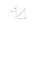
図21〜23は、プリンタのキャリブレーションを説明する図である。
【0133】
C、M、Y、Kはプリンタの濃度であり、ここでは各8bitに正規化されている。
【0134】
初期状態では、濃度の変化はなく、図21のようにC、M、Y、KはC'、M'、Y'、K'と同じ値を取る。ところが、温度・湿度の影響や経年変化等の影響により、印刷濃度が変化をするため、図22のようにC、M、Y、KはC'、M'、Y'、K'と同じ値を取らない場合が出て来る。
【0135】
図22を補正するためには、図23のように、図22の変化を打ち消すような補正処理を設定することが必要であり、その処理は一般的にキャリブレーション処理と呼ばれている。
【0136】
ここでは、図21の入力C、M、Y、Kの前段で、C"、M"、Y"、K"からC、M、Y、Kへの変換を行うことによって補正を行うことができる。
【0137】
図24は、プリンタプロファイルのデータ格納部に格納されるカラーマッチングのためのデータを説明する図である。このデータは、ICC(International Color Consortium)のプロファイルフォーマット仕様に則しており、デバイス非依存の色空間であるPCS(Profile Connection Spaceで、CIEXYZまたはCIELab)からプリンタ色空間(ここではCMYK)への変換において、80〜83によって順次行われる際の変換のためのデータがプリンタプロファイルに格納されることになる。80は3行3列の行列演算、81・83は1次元のLUT(Look Up Table)を介する処理、82は3次元のLUTを介する処理を示している。
【0138】
図25は、図24の83部分において、入出力がCMYKのデータの場合を示しており、ここにキャリブレーションの補正データを入れることにより、図23の補正処理を行う。
【0139】
このように、プリンタプロファイル内の1部のデータを用いて、カラーマッチング時にキャリブレーション処理を行う。
【0140】
図27は本実施形態におけるネットワークシステムの構成を示す図である。
【0141】
図27のように、本実施形態によるネットワークシステムは、ネットワーク端末10・20、ネットワークサーバー40、ネットワークプリンタ50、スキャナ60、濃度計70及び前記4つのデバイスが接続されるネットワーク30から構成されている。
【0142】
ネットワーク端末10は、モニタ表示や画像処理に必要なCPU・VRAM等及びネットワーク上の通信に必要な通信機能を備え、モニタの識別のためのモニタ記述情報格納部11とネットワークプリンタ40の識別のためのプリンタ記述情報格納部12を有している。
【0143】
ネットワークサーバー40は、画像処理や印刷処理に必要なCPU・RAM・ハードディスク等及びネットワーク上の通信に必要な通信機能を備え、n個(nは定数)のCMMが登録されているCMM格納部41、m個(mは定数)のデバイスプロファイル(モニタ・スキャナ・プリンタ)が格納されているプロファイル格納部42、キャリブレーションデータが格納されたプリンタプロファイルが格納されるキャリブレーションプロファイル格納部43、濃度計を制御して色パッチ出力の濃度を測定し、そのデータを取り込む機能を持つ濃度計制御プログラム44、スキャナを制御して色パッチ出力を読み取り、その読み込みデータを取り込む機能を持つスキャナ制御プログラム45、濃度計制御プログラム44やスキャナ制御プログラム45で取り込まれたデータをもとにキャリブレーションデータを作成する機能を持つキャリブレーションプログラム46を有している。
【0144】
また、スキャナ60と濃度計70は、ネットワークサーバー40に接続されている。
【0145】
CMM格納部41に登録されているCMMはそれぞれ識別のための登録情報(例.4バイトの英数字でUCCM)を有している。
【0146】
図26は、キャリブレーションプログラム46を実行時に、ユーザーに対してキャリブレーションの精度を選択させる際のユーザーインターフェース(ダイアログ)を示している。ここでは、通常精度よりもさらに高い精度をユーザーが求める場合には、「高精度」を選択することになる。
【0147】
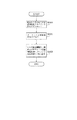
図28〜29は、ネットワークサーバー40において、ネットワークプリンタ50のキャリブレーションデータを作成し、それをプリンタプロファイルの中に格納してキャリブレーションプロファイルを作成し、プロファイル格納部に格納されているデバイスの種類に対応したオリジナルのプリンタプロファイルとは別に格納する処理のフロチャートを示している。
【0148】
ステップS1600で、ネットワーク端末10からサーバー40に対して、キャリブレーションプログラム46の起動を要求して、起動してステップS1601に進む。
【0149】
ステップS1601で、ネットワーク端末10からサーバー40に対して、キャリブレーションデータ作成のための色パッチデータの、ネットワークプリンタ50による印刷をサーバー40に要求してステップS1602に進む。
【0150】
ステップS1602で、ネットワークプリンタ50で色パッチデータを印刷してステップS1603へ進む。
【0151】
ステップS1603で、起動したキャリブレーションプログラム46で、図24のキャリブレーションの精度選択のためのダイアログを表示して、ユーザーが精度を選択してステップS1604に進む。
【0152】
ステップS1604で、通常精度選択の場合には、ステップS1605に進んで、ネットワーク端末10からサーバー40に対して、サーバー40にあるスキャナ制御プログラム45の起動要求して、起動してステップS1606に進む。
【0153】
ステップS1606で、ステップS1602で印刷された色パッチデータ出力をスキャナ60で読み込んでステップS1609に進む。
【0154】
ステップS1604で、高精度選択の場合には、ステップS1607に進んで、ネットワーク端末10に対して、サーバー40にある濃度計制御プログラム44をの起動要求して、起動してステップS1608に進む。
【0155】
ステップS1608で、ステップS1602で印刷された色パッチデータ出力を濃度計70により読み取ってステップS1609に進む。
【0156】
ステップS1609で、ステップS1606またはS1608で得られたデータをもとに、キャリブレーションプログラム46により図22の1次元LUTデータを作成してステップS1610に進む。
【0157】
ステップS1610で、サーバー40にあるプロファイル格納部42からネットワークプリンタ50のプリンタプロファイルをサーバー40で取り出してステップS1611に進む。
【0158】
ステップS1611で、S1609で作成された1次元のLUTデータをステップS1610で取り出されたプリンタプロファイルに格納してステップS1612に進む。
【0159】
ステップS1612で、1次元のLUTデータが追加格納されたプリンタプロファイルをキャリブレーションプロファイルとしてサーバー40のキャリブレーションプロファイル格納部43に格納して処理を終了する。
【0160】
このように、サーバー40にあるキャリブレーションプログラムを起動し、サーバー40でキャリブレーションデータを作成して、プリンタプロファイルにそのデータを追加することが可能である。
【0161】
また、上記キャリブレーション処理ではオリジナルのプリンタプロファイルとは別にキャリブレーションプロファイルを格納するので、オリジナルのプリンタプロファイルが変更されることがない。したがって、同一機種のプリンタがネットワークに接続されている場合でも、他のプリンタのキャリブレーションの影響を受けることなく良好なカラーマッチング処理を行うことができる。
【0162】
図30〜32は、文書をネットワークプリンタ50を用いて印刷する際に、図28〜29で作成されたキャリブレーションプロファイルを用いて、文書中のデータに対してネットワークサーバー40でカラーマッチング処理を施して、ネットワークプリンタ50に出力する場合の処理のフロチャートを示している。
【0163】
ステップS1700で、印刷する文書中に画像ファイルがあるかどうかチェックする。
【0164】
ここで、ない場合には文書中のデータはすべてモニタ上で作成されたものとみなすことができ、ネットワーク端末10のモニタとネットワークプリンタ50とのカラーマッチング処理を行うことになる。
【0165】
ステップS1711に進んでネットワーク端末10のモニタのモニタプロファイルをネットワークサーバー40で取り出してステップS1712に進む。
【0166】
ステップS1712でネットワークプリンタ50のキャリブレーションデータが格納されているプリンタプロファイルをキャリブレーションプロファイル格納部43からネットワークサーバー40に取り出して、ステップS1713に進む。
【0167】
ステップS1713で、ダウンロードしたプリンタプロファイルのヘッダー部のCMM情報を取り出してステップS1714に進む。
【0168】
ステップS1714で、ステップS1713で取り出したCMM情報に一致するCMMをネットワークサーバー40で取り出してステップS1715に進む。
【0169】
ステップS1700で画像ファイルがある場合には、ステップS1701へ進んで上記の画像ファイルにプロファイルが付いているかどうかチェックする。
【0170】
ここで、付いている場合にはステップS1702に進んでデバイスプロファイルを取り出してステップS1704へ進む。
【0171】
このプロファイルはスキャナやモニタ等のプロファイルであり、ソースプロファイルとなる。
【0172】
ステップS1701で付いていない場合には、ステップS1703に進んで、ネットワーク端末10のモニタのモニタプロファイルをネットワークサーバー40で取り出してステップS1704に進む。
【0173】
ステップS1704で、ネットワークプリンタ50の、キャリブレーションデータが格納されているプリンタプロファイルをキャリブレーションプロファイル格納部43からサーバー40で取り出してステップS1705に進む。
【0174】
ステップS1705で、取り出したプリンタプロファイルのヘッダー部のCMM情報を取り出してステップS1706に進む。
【0175】
ステップS1706で、ステップS1705で取り出したCMM情報に一致するCMMをCMM格納部41からサーバー40で取り出してステップS1707に進む。
【0176】
ステップS1707で、文書中の画像ファイルから画像データを取り出してステップS1708に進む。
【0177】
ステップS1708で、ステップS1702またはステップS703で取り出されたソースプロファイルとステップS1704で取り出されたプリンタプロファイルをCMMにセットしてステップS1709に進む。
【0178】
ステップS1709で、ステップS1707で取り出された画像データに対してステップS1708のCMMを用いて、サーバー40側でカラーマッチング処理を行う。
【0179】
これまでの処理で、必要なソースプロファイル及びキャリブレーションデータが格納されているプリンタプロファイル及びCMMをネットワークサーバー40で取り出して、ネットワークサーバー40側で文書中の画像データに対してカラーマッチング処理を行うことが可能であることがわかる。
【0180】
さらにステップS1710に進んでネットワーク端末1のモニタのモニタプロファイルをネットワークサーバー40で取り出してステップS1715に進む。
【0181】
ステップS1715で、文書中の画像以外のデータ(文字やグラフィックス等)を取り出してステップS1716に進む。
【0182】
ステップS1716で、ステップS1710またはステップS1711でダウンロードされたモニタプロファイル(ソースプロファイル)とステップS1704またはステップS1712でサーバー40で取り出されたプリンタプロファイルをCMMにセットしてステップS1717に進む。
【0183】
ステップS1717で、ステップS1715で取り出された画像以外のデータに対してステップS1716のCMMを用いてカラーマッチング処理を行い、ステップS1718に進む。
【0184】
これまでの処理で、必要なソースプロファイル及びキャリブレーションデータが格納されているプリンタプロファイル及びCMMをサーバー40で取り出し、サーバー40側で文書中の画像以外のデータに対してカラーマッチング処理を行うことが可能であることがわかる。
【0185】
ステップS1718で、ステップS1709及びステップS1717でマッチングされたデータをネットワークプリンタ50で出力可能なようにサーバー40上でビットマップに展開してステップS1719に進む。
【0186】
ステップS1719で、ステップS1718で展開されたビットマップデータをネットワークサーバー40からネットワークプリンタ50にネットワーク30を介して送信してステップS1720に進む。
【0187】
ステップS1720で、ステップS1719で送信されたビットマップデータをネットワークプリンタ50が受け取り印刷して処理を終了する。
【0188】
このように、必要なソースプロファイル及びキャリブレーションデータが格納されているプリンタプロファイル及びCMMをネットワークサーバー40で取り出し、ネットワークサーバー40側で文書中の画像データ及び画像以外のデータに対して、キャリブレーション処理を含めた形でカラーマッチング処理を行い、ネットワークプリンタ50で印刷することが可能である。
【0189】
図33は、ステップS1703・S1710・S1711でネットワーク端末10のモニタのモニタプロファイルをネットワークサーバー40で取り出す場合の詳細処理を示している。
【0190】
ステップS1800で、モニタ記述情報格納部11からネットワーク端末10のモニタのモニタ記述情報をネットワーク端末10からダウンロードしてステップS1801に進む。
【0191】
ステップS1801で、ネットワークサーバー40のプロファイル格納部42にアクセスしてステップS1802に進む。
【0192】
ステップS1802で、モニタ記述情報と一致するプロファイル記述情報を持つプロファイルを検索し、取り出して処理を終了する。
【0193】
このように、ネットワーク端末10のモニタのモニタプロファイルをネットワークサーバー40で取り出すことが可能である。
【0194】
図34は、ステップS1704・S1712で、ネットワークプリンタ50のキャリブレーションデータが格納されているプリンタプロファイルをネットワークサーバー40で取り出す場合の詳細処理を示している。
【0195】
ステップS1900で、プリンタ記述情報格納部12からネットワークプリンタ50のプリンタ記述情報をネットワーク端末10からダウンロードしてステップS1901に進む。
【0196】
ステップS1901で、ネットワークサーバー40のキャリブレーションプロファイル格納部43にアクセスしてステップS1902に進む。
【0197】
ステップS1902で、プリンタ記述情報と一致するプロファイル記述情報を持つ、キャリブレーションデータが格納されているプリンタプロファイルを取り出して処理を終了する。
【0198】
このように、ネットワークプリンタ50の、キャリブレーションデータが格納されているプリンタプロファイルをネットワークサーバー40で取り出すことが可能である。
【0199】
図35は、ステップS1706またはS714において、カラーマッチング処理に使用するCMMをネットワークサーバー40で取り出す場合の詳細処理を示している。
【0200】
ステップS1910で、ネットワークサーバー4のCMM格納部41にアクセスしてステップS1911に進む。
【0201】
ステップS1910で、ステップS1705またはS1713で取り出された、キャリブレーションデータが格納されているプリンタプロファイルのCMM情報と一致するCMMの登録情報を持つCMMを検索して取り出して処理を終了する。
【0202】
このように、カラーマッチング処理に使用するCMMをネットワークサーバー4で取り出すことが可能である。
【0203】
(実施形態3)
実施形態3では、実施形態2と異なる方法でサーバに格納されているデバイスプロファイルをキャリブレーションする方法を説明する。
【0204】
図36は実施形態3におけるネットワークシステムの構成を示す図である。なお、図36において図27と同様の構成は同一の符号を付けている。
【0205】
図36のように、本実施形態によるネットワークシステムは、ネットワーク端末10・20、ネットワークサーバー40、ネットワークプリンタ50、スキャナ60、濃度計70及び前記4つのデバイスが接続されるネットワーク30から構成されている。
【0206】
ネットワーク端末10は、モニタ表示や画像処理に必要なCPU・VRAM等及びネットワーク上の通信に必要な通信機能を備え、さらに、モニタを識別するためのモニタ記述情報を格納するモニタ記述情報格納部11とネットワークプリンタ50の識別のためのプリンタ記述情報を格納するプリンタ記述情報格納部12とを有している。
【0207】
ネットワークサーバー40は、画像処理や印刷処理に必要なCPU・RAM・ハードディスク等及びネットワーク上の通信に必要な通信機能を備え、n個(nは定数)のCMMが登録されているCMM格納部41、m個(mは定数)のデバイスプロファイル(モニタ・スキャナ・プリンタ)が格納されているプロファイル格納部42、キャリブレーションデータが格納されたプリンタプロファイルが格納されるキャリブレーションプロファイル格納部43、濃度計を制御して色パッチ出力の濃度を測定し、そのデータを取り込む機能を持つ濃度計制御プログラム44、スキャナを制御して色パッチ出力を読み取り、その読み込みデータを取り込む機能を持つスキャナ制御プログラム45、濃度計制御プログラム44やスキャナ制御プログラム45で取り込まれたデータをもとにキャリブレーションデータを作成する機能を持つキャリブレーションプログラム46を有している。
【0208】
また、スキャナ60と濃度計70は、ネットワーク端末10に接続されている。CMM格納部41に登録されているCMMはそれぞれ識別のための登録情報(例.4バイトの英数字でUCCM)を有している。
【0209】
図26は、キャリブレーションプログラム46を実行時に、ユーザーに対してキャリブレーションの精度を選択させる際のユーザーインターフェース(ダイアログ)を示している。ここでは、通常精度よりもさらに高い精度をユーザーが求める場合には、「高精度」を選択することになる。
【0210】
図37〜38は、ネットワーク端末10において、ネットワークプリンタ50のキャリブレーションデータを作成し、それをプリンタプロファイルの中に格納してキャリブレーションプロファイルを作成・格納する場合の処理のフロチャートを示している。
【0211】
ステップS1100で、ネットワーク端末10に、サーバー40にあるキャリブレーションプログラム46をダウンロードしてステップS1101に進む。
【0212】
ステップS1101で、ネットワーク端末10からネットワークプリンタ50にキャリブレーション作成のための色パッチデータを送信してステップS1102に進む。
【0213】
ステップS1102で、ネットワークプリンタ50で色パッチデータを印刷してステップS1103へ進む。
【0214】
ステップS1103で、キャリブレーションプログラム46を起動し、図26のキャリブレーションの精度選択のためのダイアログを表示して、ユーザーが精度を選択してステップS1104に進む。
【0215】
ステップS1104で、通常精度選択の場合には、ステップS1105に進んで、ネットワーク端末1にサーバー40にあるスキャナ制御プログラム45をダウンロードしてステップS1106に進む。
【0216】
ステップS1106で、ステップS1102で印刷された色パッチデータ出力をスキャナ60で読み込んでステップS1109に進む。
【0217】
ステップS1104で、高精度選択の場合には、ステップS1107に進んで、ネットワーク端末10にサーバー40にある濃度計制御プログラム44をダウンロードしてステップS1107に進む。
【0218】
ステップS1107で、ステップS1102で印刷された色パッチデータ出力を濃度計70により読み取ってステップS1109に進む。
【0219】
ステップS1109で、ステップS1106またはS1108で得られたデータをもとに、キャリブレーションプログラム46により図22の1次元LUTデータを作成してステップS1110に進む。
【0220】
ステップS1110で、ネットワーク端末10に、サーバー40にあるプロファイル格納部42からネットワークプリンタ50のプリンタプロファイルをダウンロードしてステップS1111に進む。
【0221】
ステップS1111で、S1109で作成された1次元のLUTデータをプリンタプロファイルに格納してステップS1112に進む。
【0222】
ステップS1112で、1次元のLUTデータが追加格納されたプリンタプロファイルをサーバー40に送信してステップS1113に進む。
【0223】
ステップS1113で、送信されたプリンタプロファイルをキャリブレーションプロファイルとしてサーバー40のキャリブレーションプロファイル格納部43に格納して処理を終了する。
【0224】
このように、サーバーから必要なプログラム等をダウンロードしてネットワーク端末10でキャリブレーションデータを作成して、プリンタプロファイルにそのデータを追加することが可能である。
【0225】
(実施形態4)
実施形態4では、実施形態2及び3に記載されている2つキャリブレーション方法を有するシステムを上記各実施形態の変形例として説明する。
【0226】
本実施形態では、図27及び図36に記載されたネットワークシステムの構成を合わせたネットワークシステムを想定している。すなわち、図36に示されているようにスキャナや濃度計が接続されているネットワーク端末や、図27に示されているように入力機器が接続されていないネットワーク端末がネットワークに接続されている。サーバ40は図27に示されているようにスキャナや濃度計が接続されている。
【0227】
本実施形態では、ユーザが状況に応じて図28〜29に記載されているキャリブレーション方法または図37〜38に記載されているキャリブレーション方法を選択することができる。
【0228】
サーバは図28のステップS1600に記載されているようにネットワーク端末からキャリブレーションプログラムの起動が要求された場合は図28〜29に記載されているキャリブレーション方法を実行する。
【0229】
一方、図37のステップS1100に記載されているようにネットワーク端末からキャリブレーションプログラムをダウンロードすることが要求された場合は図37〜38に記載されているキャリブレーション方法を実行する。
【0230】
本実施形態のように、複数のキャリブレーション方法を選択できるようにすることにより、ユーザの用途に応じたキャリブレーション処理を実行することができる。
【0231】
本実施形態では、キャリブレーション処理を実行する機器(ネットワーク端末/サーバ)を選択することができるので、各機器の負荷の状況に応じて選択することにより、効率的に処理を実行することができる。
【0232】
また、例えば、ネットワーク端末が独自のキャリブレーションプログラムを持っている場合は、サーバから所望のデバイスプロファイルをダウンロードし、独自のキャリブレーションプログラムを用いてネットワーク端末でキャリブレーション処理を実行しても構わない。このキャリブレーション方法によれば、ネットワークサーバがサポートしているキャリブレーション方法より高精度のキャリブレーションを行うことが可能となる。ネットワークシステムの枠組みを利用しながら、ユーザの用途に応じたキャリブレーション処理を行うことができる。すなわち、ユーザのキャリブレーション処理に対する自由度が高くなる。
【0233】
(他の実施の形態)
前述した実施形態の機能を実現する様に各種のデバイスを動作させる様に該各種デバイスと接続された装置あるいはシステム内のコンピュータに、前記実施形態機能を実現するためのソフトウエアのプログラムコードを供給し、そのシステムあるいは装置のコンピュータ(CPUあるいはMPU)を格納されたプログラムに従って前記各種デバイスを動作させることによって実施したものも本発明の範疇に含まれる。
【0234】
またこの場合、前記ソフトウエアのプログラムコード自体が前述した実施形態の機能を実現することになり、そのプログラムコード自体、及びそのプログラムコードをコンピュータに供給するための手段、例えばかかるプログラムコードを格納した記憶媒体は本発明を構成する。
【0235】
かかるプログラムコードを格納する記憶媒体としては例えばフロッピーディスク、ハードディスク、光ディスク、光磁気ディスク、CD-ROM,、磁気テープ、不揮発性のメモリカード、ROM等を用いることが出来る。
【0236】
またコンピュータが供給されたプログラムコードを実行することにより、前述の実施形態の機能が実現されるだけではなく、そのプログラムコードがコンピュータにおいて稼働しているOS(オペレーティングシステム)、あるいは他のアプリケーションソフト等と共同して前述の実施形態の機能が実現される場合にもかかるプログラムコードは本発明の実施形態に含まれることは言うまでもない。
【0237】
更に供給されたプログラムコードが、コンピュータの機能拡張ボードやコンピュータに接続された機能拡張ユニットに備わるメモリに格納された後そのプログラムコードの指示に基づいてその機能拡張ボードや機能格納ユニットに備わるCPU等が実際の処理の一部または全部を行い、その処理によって前述した実施形態の機能が実現される場合も本発明に含まれることは言うまでもない。
【0238】
【発明の効果】
以上説明したように、本発明によればネットワークシステム上でカラーマッチングを実現することができる。
【0239】
また、常に高品質の出力画像を得られるようにデバイスプロファイルをキャリブレートすることができる、使い勝手の良い画像処理方法を提供することができる。
【図面の簡単な説明】
【図1】カラーマネージメントシステムの概念図
【図2】デバイスプロファイルの構造の一例を示す図
【図3】本発明の一実施形態によるネットワークシステムの構成を示す図
【図4】ネットワーク端末1において文書を表示する際に、文書中に画像ファイルが存在する場合にモニタの特性に合わせて画像ファイル中の画像データに対してネットワークサーバ3側でカラーマッチング処理を施して、その結果をネットワーク端末1のモニタに表示する場合の処理のフローチャート
【図5】ネットワーク端末1において文書を表示する際に、文書中に画像ファイルが存在する場合にモニタの特性に合わせて画像ファイル中の画像データに対してネットワークサーバ3側でカラーマッチング処理を施して、その結果をネットワーク端末1のモニタに表示する場合の処理のフローチャート
【図6】ネットワーク端末1において文書を表示する際に、文書中に画像ファイルが存在する場合にモニタの特性に合わせて画像ファイル中の画像データに対してネットワークサーバ3側でカラーマッチング処理を施して、その結果をネットワーク端末1のモニタに表示する場合の処理のフローチャート
【図7】文書をネットワークプリンタ4を用いて印刷する際に、ネットワークプリンタ4の特性に合わせて、文書中のデータに対してネットワークサーバー3がカラーマッチング処理を施して、ネットワークプリンタ4に出力する場合の処理のフローチャート
【図8】文書をネットワークプリンタ4を用いて印刷する際に、ネットワークプリンタ4の特性に合わせて、文書中のデータに対してネットワークサーバー3がカラーマッチング処理を施して、ネットワークプリンタ4に出力する場合の処理のフローチャート
【図9】文書をネットワークプリンタ4を用いて印刷する際に、ネットワークプリンタ4の特性に合わせて、文書中のデータに対してネットワークサーバー3がカラーマッチング処理を施して、ネットワークプリンタ4に出力する場合の処理のフローチャート
【図10】図4のステップS107及び図7のステップS210における詳細処理のフローチャート
【図11】図4のステップS107及び図7のステップS210における詳細処理のフローチャート
【図12】図4のステップS109及び図7のS212における詳細処理のフローチャート
【図13】図5のステップS113、図9のS201、図7のS209、図9の詳細処理のフローチャート
【図14】図13のステップS802の詳細処理のフローチャート
【図15】図5のステップS115、図8のステップS215、図9のステップS203の詳細処理のフローチャート
【図16】図5のステップS115、図8のステップS215、図9のステップS203の詳細処理のフローチャート
【図17】図8のステップS214、図9のステップS202の詳細処理のフローチャート
【図18】図17のステップS902の詳細処理のフローチャート
【図19】ユーザーインターフェースの一例を示す図
【図20】ユーザーインターフェースの一例を示す図
【図21】プリンタのキャリブレーションに関する説明のための図
【図22】印刷濃度の変化を示す図
【図23】図22の変化を打ち消すような補正を示す図
【図24】プリンタプロファイルのデータ格納部に格納されるカラーマッチングのためのデータに関して説明する図
【図25】図24の83部分の一例を示す図
【図26】ユーザーに対してキャリブレーションの精度を選択させる際のユーザーインターフェース(ダイアログ)の一例
【図27】実施形態2によるネットワークシステムの構成を示す図
【図28】ネットワークサーバー40において、ネットワークプリンタ50のキャリブレーションデータを作成し、それをプリンタプロファイルの中に格納してキャリブレーションプロファイルを作成・格納する場合の処理のフロチャート
【図29】ネットワークサーバー4において、ネットワークプリンタ5のキャリブレーションデータを作成し、それをプリンタプロファイルの中に格納してキャリブレーションプロファイルを作成・格納する場合の処理のフロチャート
【図30】文書をネットワークプリンタ50を用いて印刷する際に、作成されたキャリブレーションプロファイルを用いて、文書中のデータに対してネットワークサーバー40でカラーマッチング処理を施して、ネットワークプリンタ50に出力する場合の処理のフロチャート
【図31】文書をネットワークプリンタ50を用いて印刷する際に、作成されたキャリブレーションプロファイルを用いて、文書中のデータに対してネットワークサーバー40でカラーマッチング処理を施して、ネットワークプリンタ50に出力する場合の処理のフロチャート
【図32】文書をネットワークプリンタ50を用いて印刷する際に、作成されたキャリブレーションプロファイルを用いて、文書中のデータに対してネットワークサーバー40でカラーマッチング処理を施して、ネットワークプリンタ50に出力する場合の処理のフロチャート
【図33】ネットワーク端末10のモニタのモニタプロファイルをネットワークサーバー40で取り出す場合の詳細処理のフロチャート
【図34】ネットワークプリンタ50のキャリブレーションデータが格納されているプリンタプロファイルをネットワークサーバー40で取り出す場合の詳細処理のフロチャート
【図35】カラーマッチング処理に使用するCMMをネットワークサーバー40で取り出す場合の詳細処理
【図36】実施形態3によるネットワークシステムの構成を示す図
【図37】ネットワーク端末10において、ネットワークプリンタ50のキャリブレーションデータを作成し、それをプリンタプロファイルの中に格納してキャリブレーションプロファイルを作成・格納する場合の処理のフロチャート
【図38】ネットワーク端末10において、ネットワークプリンタ50のキャリブレーションデータを作成し、それをプリンタプロファイルの中に格納してキャリブレーションプロファイルを作成・格納する場合の処理のフロチャート[0001]
BACKGROUND OF THE INVENTION
The present invention relates to a network server that communicates with a network terminal via a network.
[0002]
[Prior art]
As described in Japanese Patent Application Laid-Open No. 07-222-009, the color management system is composed of a CMM (Color Management Module) and a device profile. Using the corresponding profile, color conversion processing is performed to perform color matching of the input / output images.
[0003]
The former profile is called a source profile, and the latter profile is called a destination device profile.
[0004]
For example, in the color conversion process shown in FIG. 1, a process of converting from a scanner color space (scanner RGB) or a monitor color space (monitor RGB) to a printer color space (printer CMYK) is performed.
[0005]
In this case, the source device is a scanner or a monitor, the profile of the scanner or monitor is a source profile, the destination device is a printer, and the profile of the printer is a destination profile.
[0006]
FIG. 2 shows an example of the structure of the device profile.
[0007]
Here, the profile is divided into a header part and a data storage part. In the header part, device information indicating which device (eg, monitor) the profile belongs to, and in which CMM the profile is used. Stored is information used for managing a profile such as CMM information. The data storage unit stores profile description information for identifying the profile. For example, information indicating a manufacturer name and a product name is stored in the profile description information.
[0008]
[Problems to be solved by the invention]
Conventionally, the color management system as described above has not been realized on a network system. In other words, the device profile used for the color conversion process and the transmission / reception between the color management modules cannot be performed systematically.
[0009]
For this reason, it is difficult to realize color matching between the transmission side and the reception side on the network.
[0010]
The present invention has been made in view of the above-described drawbacks of the conventional example, and an object thereof is to realize color matching on a network system.
[0011]
It is another object of the present invention to provide an easy-to-use image processing method capable of calibrating a device profile so that a high-quality output image can always be obtained.
[0012]
[Means for Solving the Problems]
In order to achieve the above object, the present invention provides a network server for communicating with a network terminal via a network, and means for receiving color management module for performing color matching processing and device profile selection information from the network terminal. And an acquisition means for acquiring a color management module and a device profile based on the selection information; Set the acquired device profile in the acquired color management module It has means for performing color matching processing on input data, and means for communicating the data subjected to color matching processing to the network terminal.
[0013]
The present invention is also an image processing method having a plurality of calibration methods, wherein an arbitrary calibration method is selected from the plurality of calibration methods, and is used for color matching processing using the selected calibration method. In accordance with the ICC profile specifications The one-dimensional LUT of a device profile having a three-dimensional LUT and a one-dimensional LUT for performing conversion from the device connection space to the printer color space Is stored, and the calibrated device profile is stored.
[0014]
DETAILED DESCRIPTION OF THE INVENTION
(Embodiment 1)
Hereinafter, an example of a preferred embodiment of the present invention will be described in detail with reference to the accompanying drawings.
[0015]
FIG. 3 is a diagram showing a configuration of a network system according to an embodiment of the present invention.
[0016]
As shown in FIG. 3, the network system according to the present embodiment includes a
[0017]
The
[0018]
The
[0019]
4 to 6, when a document is displayed on the
[0020]
In step S100, it is checked whether there is an image file in the document to be displayed. If there is no image file, the process advances to step S101 to display the document data without matching processing, and the process ends. On the other hand, if there is an image file, the process proceeds to step S102 to check whether the image file has a profile.
[0021]
If a profile is attached in step 102, the process proceeds to step S103, a device profile is extracted, and the process proceeds to step S104.
[0022]
In step S104, the profile extracted in step S103 is transmitted to the
[0023]
If no profile is attached in step S102, the process proceeds to step S105, and whether or not the scanner that has read the image data is designated is displayed on the monitor as shown in FIG. 19, and the process proceeds to step S106.
[0024]
In step S106, a user instruction indicating whether to designate a scanner is checked. If it is instructed not to designate a scanner, the process proceeds to step S101, where the document data is displayed on the monitor without matching processing, and the process is terminated. This is a case where the user cannot specify the scanner that has read the image data.
[0025]
If it is instructed in step S106 to designate a scanner, the process proceeds to step S107. In this case, the user can specify the scanner that has read the image data.
[0026]
In step S107, a list of selectable scanner profiles in the profile storage unit 32 of the
[0027]
In step S108, the user selects one scanner profile from the list, and the process advances to step S109.
[0028]
In step S109, the
[0029]
In step S110, the
[0030]
In step S111, the monitor description information of the
[0031]
In step S112, the monitor description information extracted in step S111 is transmitted to the
[0032]
In step S113, based on the monitor description information transmitted in step S113, the
[0033]
In step S114, the monitor profile extracted in step S113 is held in the
[0034]
In step S115, the
[0035]
In step S116, the CMM extracted in step S115 is held by the
[0036]
In step S117, image data is extracted from the image file in the document, and the process proceeds to step S118.
[0037]
In step S118, the source profile extracted in step S103 or step S109 and the monitor profile extracted in step S113 are set in the CMM, and the process proceeds to step S119.
[0038]
In step S119, color matching processing is performed on the image data extracted in step S117 using the CMM in step S118, and the process proceeds to step S120.
[0039]
In step S120, the data subjected to the color matching process in step S119 is transmitted from the
[0040]
In step S121, the transmission data in step S121 is displayed on the monitor of the
[0041]
By processing in this way, necessary profiles and CMMs can be extracted from the
[0042]
7 to 9, when a document is printed using the
[0043]
In step S200, it is checked whether there is an image file in the document to be printed. Here, if there is no image file, all data in the document can be regarded as being created on the monitor, and color matching processing between the monitor of the
[0044]
In this case, the process proceeds to step S201, the monitor profile of the monitor of the
[0045]
In step S202, the
[0046]
In step S203, the CMM used for processing is retrieved from the CMM storage unit 31 to the
[0047]
If there is an image file in step S200, the process proceeds to step S204 to check whether the image file has a profile. If a profile is attached, the process proceeds to step S205, a device profile is extracted, and the process proceeds to step S206. This profile is a profile of a scanner, a monitor, etc., and becomes a source profile.
[0048]
In step S206, the profile extracted in step S205 is transmitted to the
[0049]
If no profile is attached in step S204, the process advances to step S207 to display on the monitor whether or not the scanner that has read the image data is designated, and the process advances to step S208.
[0050]
In step S208, a user instruction indicating whether or not the user designates a scanner is checked. If it is instructed not to designate a scanner, the process proceeds to step S209, the monitor profile of the monitor of the
[0051]
This is a case where the user cannot specify the scanner that has read the image data, and indicates that the color matching source device for the document is the monitor of the
[0052]
On the other hand, if it is instructed to designate a scanner in step S208, the process proceeds to step S210. In this case, the user can specify the scanner that has read the image data.
[0053]
In step S210, a list of selectable scanner profiles in the profile storage unit 33 of the
[0054]
In step S211, the user selects one scanner profile from the list, and the process advances to step S212.
[0055]
In step S212, the scanner profile selected in step S211 is instructed to be taken out by the
[0056]
In step S213, the
[0057]
In step S214, the
[0058]
In step S215, the CMM used for processing is retrieved from the CMM storage unit 31 to the
[0059]
In step S216, image data is extracted from the image file in the document, and the process proceeds to step S217.
[0060]
In step S217, the source profile (monitor profile or scanner profile) extracted in step S205, step S209, or step S212 and the printer profile extracted in step S214 are set in the CMM, and the process proceeds to step S218.
[0061]
In step S218, color matching processing is performed on the image data extracted in step S216 using the CMM in step S217, and the process proceeds to step S219.
[0062]
Through the processing so far, it is possible to instruct the
[0063]
Further, the process proceeds to step S219, where the matching data in step S218 is held by the
[0064]
In step S220, the monitor profile of the monitor of the
[0065]
In step S221, data (characters, graphics, etc.) other than the image in the document is extracted, and the process proceeds to step S222.
[0066]
In step S222, the monitor profile (source profile) extracted in step S201 or step S220 and the printer profile extracted in step S202 or step S214 are set in the CMM in step S203 or step S215, and the image extracted in step S221. Color matching processing is performed on data other than the above, and the process proceeds to step S223.
[0067]
Through these processes, it is possible to instruct the
[0068]
In step S223, the data matched in steps S218 and S222 is developed into a bitmap on the
[0069]
In step S224, the bitmap data expanded in step S223 is transmitted from the
[0070]
In step S225, the
[0071]
As described above, according to the present embodiment, the necessary profile and CMM are instructed to be extracted from the network server, and color matching processing is performed on the image data and data other than the image in the document on the
[0072]
10 and 11 show in detail the process of displaying a list of selectable scanner profiles in the profile storage unit 32 of the
[0073]
In step S300, the profile storage unit 32 of the
[0074]
In step S301, the header information of the head profile in the profile storage unit 32 is read, and the process proceeds to step S302.
[0075]
In step S302, device information is extracted from the header information read in step S301, and the process proceeds to step S303.
[0076]
In step S303, it is checked whether the device information is a scanner. If it is different from the scanner, the process proceeds to step S304, and it is checked whether or not the profile currently reading the header information is the last. Here, if it is the last, it progresses to step S310. On the other hand, if it is not the last, it progresses to step S305, reads the header information of the next profile, and returns to step S302.
[0077]
If it is determined in step S303 that the device information indicates a scanner, the process advances to step S306 to extract profile description information in the profile data storage unit, and the process advances to step S307.
[0078]
In step S307, the profile description information extracted in step S306 is temporarily stored in the RAM or the like of the
[0079]
In step S308, it is checked whether or not the profile currently reading the header information is the last. If it is not the last, the process proceeds to step S309, the header information of the next profile is read, and the process returns to step S302. On the other hand, if it is the last, it progresses to step S310, the profile description information temporarily stored by step S307 is displayed on a monitor as a list, and it progresses to step S311.
[0080]
In step S311, a screen prompting the user to select which one to select is displayed on the monitor, and the process ends.
[0081]
Such a list of selectable scanner profiles in the profile storage unit 32 of the
[0082]
FIG. 12 shows in detail the processing performed in steps S109 and S212 by instructing the
[0083]
In step S400, profile description information in the data storage unit of the selected scanner profile is extracted, and the process proceeds to step S401.
[0084]
In step S401, the profile storage unit 32 of the
[0085]
In step S402, the profile description information in the data storage unit of the first profile in the profile storage unit 32 is extracted, and the process proceeds to step S403.
[0086]
In step S403, it is checked whether the profile description information extracted in step S402 matches the profile description information extracted in step S400. If they do not match, the process proceeds to step S305, the profile description information in the data storage unit of the next profile is extracted, and the process returns to step S403. On the other hand, if they match in step S403, the process proceeds to step S405, the profile is extracted from the
[0087]
In this way, it is possible to instruct the
[0088]
FIG. 13 shows in detail the processing performed in steps S113, S201, S209, and S220 for instructing the
[0089]
In step S800, the description information of the monitor profile of the
[0090]
In step S801, the description information of the monitor profile extracted in step S800 is transmitted to the
[0091]
In step S802, the
[0092]
In step S803, the
[0093]
By processing in this way, the monitor profile of the monitor of the
[0094]
FIG. 14 shows the details of the processing performed in step S802 to instruct the
[0095]
In step S500, the
[0096]
In step S501, the profile storage unit 32 of the
[0097]
In step S502, the profile description information in the data storage unit of the first profile in the profile storage unit 32 is extracted, and the process proceeds to step S503.
[0098]
In step S503, it is checked whether the profile description information extracted in step S502 matches the monitor description information extracted in step S500. If they do not match, the process advances to step S505 to check whether the profile currently reading the profile description information is the last one.
[0099]
If it is the last, the process proceeds to step S507, the default monitor profile of the
[0100]
If they match in step S503, the process proceeds to step S504, the profile is extracted from the
[0101]
By processing in this way, it is possible to instruct the
[0102]
FIGS. 15 and 16 show in detail the processing performed in steps S115, S203, and S215 for instructing the
[0103]
In step S700, the CMM information of the destination profile (monitor profile in the case of monitor display, printer profile in the case of printing) is held, and the process proceeds to step S701.
[0104]
In step S701, the CMM storage unit 31 of the
[0105]
In step S702, the registration information of the first CMM in the CMM storage unit 31 is extracted, and the process proceeds to step S703.
[0106]
In step S703, it is checked whether the CMM information extracted in step S702 matches the CMM information held in step S700. If they match, the process proceeds to step S710. On the other hand, if they do not match, the process advances to step S704 to check whether the CMM that is currently reading registration information is the last.
[0107]
If it is not the last, the process proceeds to step S705, where the registration information of the next CMM is read, and the process returns to step S703. On the other hand, in the last case, the process proceeds to step S706, the CMM information of the source profile is extracted, and the process proceeds to step S707.
[0108]
In step S707, the CMM storage unit 31 of the
[0109]
In step S708, the CMM registration information of the first profile in the CMM storage unit 31 is extracted, and the process proceeds to step S709.
[0110]
In step S709, it is checked whether the CMM information extracted in step S708 matches the CMM information of the source profile extracted in step S706. If they do not match, the process advances to step S711 to check whether the profile currently reading the CMM registration information is the last one.
[0111]
Here, if it is the last, the process proceeds to step S712, where the default CMM of the
[0112]
If they match in step S709, the process proceeds to step S710, where the CMM is taken out from the
[0113]
By processing in this way, it is possible to instruct the
[0114]
FIG. 17 shows in detail the processing performed in steps S202 and S214 to instruct the
[0115]
In step S900, the printer profile description information of the
[0116]
In step S901, the printer profile description information extracted in step S900 is transmitted to the
[0117]
In step S902, the
[0118]
In step S903, the printer profile extracted in step S902 is held by the
[0119]
By processing in this way, it is possible to instruct the
[0120]
FIG. 18 shows in detail the processing performed in step S902 by instructing the
[0121]
In step S600, the printer description information of the
[0122]
In step S601, the profile storage unit 32 of the
[0123]
In step S602, the profile description information in the data storage unit of the first profile in the profile storage unit 32 is extracted, and the process proceeds to step S603.
[0124]
In step S603, it is checked whether the profile description information extracted in step S602 matches the printer description information extracted in step S600. If they do not match, the process proceeds to step S604, the profile description information in the data storage unit of the next profile is extracted, and the process returns to step S603. On the other hand, if they match, the process proceeds to step S605, the profile is extracted from the
[0125]
By processing in this way, it is possible to instruct the
[0126]
FIG. 19 shows an example of the user interface at the time of step S107 in FIG. 4 or step S210 in FIG. 7. In this figure, the user selects “designate”.
[0127]
FIG. 20 shows an example of a user interface in step S106 of FIG. 4 or step S210 of FIG. 6, and a list of manufacturer names and scanner product names is displayed.
[0128]
In this figure, the arrow points to Company C A-4015, and when the user presses the selection button as it is, Company C A-4015 is selected.
[0129]
(Embodiment 2)
In the first embodiment, the profile stored in the network server is not changed according to a change in device characteristics.
[0130]
Therefore, there is an improvement in that good color matching processing cannot be performed when the characteristics of the device change due to aging or environmental changes.
[0131]
In the second embodiment, a system having a profile calibration function will be described as a modification of the first embodiment.
[0132]
21 to 23 are diagrams for explaining printer calibration.
[0133]
C, M, Y, and K are printer densities, which are normalized to 8 bits each here.
[0134]
In the initial state, there is no change in density, and C, M, Y, and K have the same values as C ′, M ′, Y ′, and K ′ as shown in FIG. However, since the print density changes due to the influence of temperature / humidity and aging, etc., C, M, Y, K are the same values as C ′, M ′, Y ′, K ′ as shown in FIG. If you don't take it out.
[0135]
In order to correct FIG. 22, it is necessary to set a correction process that cancels the change in FIG. 22 as shown in FIG. 23. This process is generally called a calibration process.
[0136]
Here, correction can be performed by performing conversion from C ", M", Y ", K" to C, M, Y, K before the input C, M, Y, K in FIG. .
[0137]
FIG. 24 is a diagram for explaining data for color matching stored in the data storage unit of the printer profile. This data conforms to the ICC (International Color Consortium) profile format specification, and is a device-independent color space from PCS (Profile Connection Space, CIEXYZ or CIELab) to the printer color space (here CMYK). In the conversion, data for conversion when sequentially performed by 80 to 83 is stored in the printer profile.
[0138]
FIG. 25 shows a case where the input / output is CMYK data at 83 in FIG. 24, and the correction processing of FIG. 23 is performed by putting calibration correction data therein.
[0139]
In this way, calibration processing is performed at the time of color matching using a part of the data in the printer profile.
[0140]
FIG. 27 is a diagram showing a configuration of a network system in the present embodiment.
[0141]
As shown in FIG. 27, the network system according to the present embodiment includes
[0142]
The
[0143]
The
[0144]
The
[0145]
Each CMM registered in the
[0146]
FIG. 26 shows a user interface (dialog) when the user selects the calibration accuracy when the
[0147]
28 to 29, the
[0148]
In step S1600, the
[0149]
In step S1601, the
[0150]
In step S1602, the color patch data is printed by the
[0151]
In step S1603, the activated
[0152]
If the normal accuracy is selected in step S1604, the process proceeds to step S1605, the
[0153]
In step S1606, the color patch data output printed in step S1602 is read by the
[0154]
In step S1604, in the case of high precision selection, the process proceeds to step S1607, the
[0155]
In step S1608, the color patch data output printed in step S1602 is read by the
[0156]
In step S1609, based on the data obtained in step S1606 or S1608, the
[0157]
In step S1610, the
[0158]
In step S1611, the one-dimensional LUT data created in step S1609 is stored in the printer profile extracted in step S1610, and the process advances to step S1612.
[0159]
In step S1612, the printer profile in which one-dimensional LUT data is additionally stored is stored in the calibration profile storage unit 43 of the
[0160]
Thus, it is possible to start the calibration program in the
[0161]
Further, since the calibration profile is stored separately from the original printer profile in the calibration process, the original printer profile is not changed. Therefore, even when printers of the same model are connected to the network, good color matching processing can be performed without being affected by calibration of other printers.
[0162]
30 to 32, when printing a document using the
[0163]
In step S1700, it is checked whether there is an image file in the document to be printed.
[0164]
If there is no data, all data in the document can be regarded as being created on the monitor, and color matching processing between the monitor of the
[0165]
Proceeding to step S 1711, the monitor profile of the monitor of
[0166]
In step S1712, the printer profile in which the calibration data of the
[0167]
In step S1713, the CMM information in the header portion of the downloaded printer profile is extracted, and the flow advances to step S1714.
[0168]
In step S1714, the CMM that matches the CMM information extracted in step S1713 is extracted by the
[0169]
If there is an image file in step S1700, the process advances to step S1701 to check whether the image file has a profile.
[0170]
If it is attached, the process proceeds to step S1702, the device profile is extracted, and the process proceeds to step S1704.
[0171]
This profile is a profile of a scanner, a monitor, etc., and becomes a source profile.
[0172]
If not attached in step S1701, the process proceeds to step S1703, the monitor profile of the monitor of the
[0173]
In step S1704, the printer profile in which calibration data is stored for the
[0174]
In step S1705, the CMM information in the header portion of the extracted printer profile is extracted, and the process advances to step S1706.
[0175]
In step S1706, the CMM that matches the CMM information extracted in step S1705 is extracted from the
[0176]
In step S1707, image data is extracted from the image file in the document, and the flow advances to step S1708.
[0177]
In step S1708, the source profile extracted in step S1702 or step S703 and the printer profile extracted in step S1704 are set in the CMM, and the process advances to step S1709.
[0178]
In step S1709, color matching processing is performed on the
[0179]
In the process so far, the printer profile and CMM in which the necessary source profile and calibration data are stored are extracted by the
[0180]
In step S1710, the monitor profile of the monitor of the
[0181]
In step S1715, data other than images (characters, graphics, etc.) in the document is extracted, and the flow advances to step S1716.
[0182]
In step S1716, the monitor profile (source profile) downloaded in step S1710 or step S1711 and the printer profile extracted by the
[0183]
In step S1717, color matching processing is performed on the data other than the image extracted in step S1715 using the CMM in step S1716, and the process proceeds to step S1718.
[0184]
In the process so far, the printer profile and CMM in which the necessary source profile and calibration data are stored are extracted by the
[0185]
In step S1718, the data matched in steps S1709 and S1717 is developed into a bitmap on the
[0186]
In step S1719, the bitmap data expanded in step S1718 is transmitted from the
[0187]
In step S1720, the
[0188]
In this way, the printer profile and CMM in which necessary source profiles and calibration data are stored are extracted by the
[0189]
FIG. 33 shows detailed processing when the
[0190]
In step S1800, monitor description information of the monitor of the
[0191]
In step S1801, the
[0192]
In step S1802, a profile having profile description information that matches the monitor description information is retrieved, and the process ends.
[0193]
Thus, the monitor profile of the monitor of the
[0194]
FIG. 34 shows detailed processing when the
[0195]
In step S1900, the printer description information of the
[0196]
In step S1901, the calibration profile storage unit 43 of the
[0197]
In step S1902, the printer profile having the profile description information that matches the printer description information and storing the calibration data is extracted, and the process ends.
[0198]
As described above, the
[0199]
FIG. 35 shows detailed processing when the
[0200]
In step S1910, the
[0201]
In step S1910, a CMM having CMM registration information that matches the CMM information of the printer profile in which the calibration data is stored, which is extracted in step S1705 or S1713, is searched and extracted, and the process ends.
[0202]
In this way, the CMM used for the color matching process can be taken out by the
[0203]
(Embodiment 3)
In the third embodiment, a method for calibrating a device profile stored in a server by a method different from that of the second embodiment will be described.
[0204]
FIG. 36 is a diagram illustrating a configuration of a network system according to the third embodiment. In FIG. 36, the same components as those in FIG.
[0205]
As shown in FIG. 36, the network system according to the present embodiment includes
[0206]
The
[0207]
The
[0208]
The
[0209]
FIG. 26 shows a user interface (dialog) when the user selects the calibration accuracy when the
[0210]
37 to 38 show flowcharts of processing when the
[0211]
In step S1100, the
[0212]
In step S1101, color patch data for calibration creation is transmitted from the
[0213]
In step S1102, the color patch data is printed by the
[0214]
In step S1103, the
[0215]
If normal accuracy is selected in step S1104, the process proceeds to step S1105, the
[0216]
In step S1106, the color patch data output printed in step S1102 is read by the
[0217]
If it is determined in step S1104 that the selection is highly accurate, the process proceeds to step S1107, the
[0218]
In step S1107, the color patch data output printed in step S1102 is read by the
[0219]
In step S1109, based on the data obtained in step S1106 or S1108, the
[0220]
In step S1110, the printer profile of the
[0221]
In step S1111, the one-dimensional LUT data created in S1109 is stored in the printer profile, and the process advances to step S1112.
[0222]
In step S1112, the printer profile additionally storing the one-dimensional LUT data is transmitted to the
[0223]
In step S1113, the transmitted printer profile is stored in the calibration profile storage unit 43 of the
[0224]
In this way, it is possible to download necessary programs from the server, create calibration data at the
[0225]
(Embodiment 4)
In the fourth embodiment, a system having the two calibration methods described in the second and third embodiments will be described as a modification of each of the above embodiments.
[0226]
In the present embodiment, a network system is assumed in which the configurations of the network systems described in FIGS. 27 and 36 are combined. That is, a network terminal to which a scanner and a densitometer are connected as shown in FIG. 36, and a network terminal to which no input device is connected as shown in FIG. 27 are connected to the network. The
[0227]
In the present embodiment, the user can select the calibration method described in FIGS. 28 to 29 or the calibration method described in FIGS.
[0228]
As described in step S1600 of FIG. 28, the server executes the calibration method described in FIGS. 28 to 29 when the activation of the calibration program is requested from the network terminal.
[0229]
On the other hand, when it is requested to download the calibration program from the network terminal as described in step S1100 of FIG. 37, the calibration method described in FIGS. 37 to 38 is executed.
[0230]
By enabling a plurality of calibration methods to be selected as in the present embodiment, calibration processing according to the user's application can be executed.
[0231]
In this embodiment, since a device (network terminal / server) that executes calibration processing can be selected, the processing can be executed efficiently by selecting according to the load status of each device. .
[0232]
For example, when the network terminal has an original calibration program, a desired device profile may be downloaded from the server, and the calibration process may be executed on the network terminal using the original calibration program. . According to this calibration method, it is possible to perform calibration with higher accuracy than the calibration method supported by the network server. While using the framework of the network system, it is possible to perform calibration processing according to the user's application. That is, the user's degree of freedom for the calibration process is increased.
[0233]
(Other embodiments)
Supplying program code of software for realizing the functions of the embodiment to a computer in an apparatus or system connected to the various devices so as to operate various devices so as to realize the functions of the above-described embodiments However, the present invention includes those implemented by operating the various devices according to a program stored in a computer (CPU or MPU) of the system or apparatus.
[0234]
In this case, the software program code itself realizes the functions of the above-described embodiments, and the program code itself and means for supplying the program code to the computer, for example, the program code are stored. The storage medium constitutes the present invention.
[0235]
As a storage medium for storing the program code, for example, a floppy disk, a hard disk, an optical disk, a magneto-optical disk, a CD-ROM, a magnetic tape, a nonvolatile memory card, a ROM, or the like can be used.
[0236]
In addition, by executing the program code supplied by the computer, not only the functions of the above-described embodiments are realized, but also the OS (operating system) in which the program code is running on the computer, or other application software, etc. It goes without saying that the program code is also included in the embodiment of the present invention even when the functions of the above-described embodiment are realized in cooperation with the embodiment.
[0237]
Further, after the supplied program code is stored in the memory provided in the function expansion board of the computer or the function expansion unit connected to the computer, the CPU provided in the function expansion board or function storage unit based on the instruction of the program code However, it is needless to say that the present invention also includes a case where the function of the above-described embodiment is realized by performing part or all of the actual processing.
[0238]
【The invention's effect】
As described above, according to the present invention, color matching can be realized on a network system.
[0239]
In addition, it is possible to provide an easy-to-use image processing method capable of calibrating a device profile so as to always obtain a high-quality output image.
[Brief description of the drawings]
FIG. 1 is a conceptual diagram of a color management system.
FIG. 2 is a diagram showing an example of the structure of a device profile
FIG. 3 is a diagram showing a configuration of a network system according to an embodiment of the present invention.
FIG. 4 shows that when a document is displayed on the
FIG. 5 shows that when a document is displayed on the
FIG. 6 shows that when a document is displayed on the
FIG. 7 shows that when a document is printed using the
FIG. 8 shows that when a document is printed using the
FIG. 9 shows that when a document is printed using the
10 is a flowchart of detailed processing in step S107 in FIG. 4 and step S210 in FIG. 7;
11 is a flowchart of detailed processing in step S107 in FIG. 4 and step S210 in FIG. 7;
12 is a flowchart of detailed processing in step S109 of FIG. 4 and S212 of FIG. 7;
13 is a flowchart of step S113 in FIG. 5, S201 in FIG. 9, S209 in FIG. 7, and detailed processing in FIG.
14 is a flowchart of detailed processing in step S802 in FIG.
15 is a flowchart of detailed processing in step S115 in FIG. 5, step S215 in FIG. 8, and step S203 in FIG.
16 is a flowchart of detailed processing in step S115 in FIG. 5, step S215 in FIG. 8, and step S203 in FIG.
17 is a flowchart of detailed processing in step S214 in FIG. 8 and step S202 in FIG. 9;
FIG. 18 is a flowchart of detailed processing in step S902 in FIG.
FIG. 19 is a diagram showing an example of a user interface
FIG. 20 is a diagram showing an example of a user interface
FIG. 21 is a diagram for explaining the printer calibration;
FIG. 22 is a diagram showing a change in printing density.
FIG. 23 is a diagram showing correction that cancels the change in FIG. 22;
FIG. 24 is a diagram for explaining color matching data stored in a printer profile data storage unit;
25 is a view showing an example of a
FIG. 26 shows an example of a user interface (dialog) when the user selects the calibration accuracy.
FIG. 27 is a diagram showing a configuration of a network system according to the second embodiment.
FIG. 28 is a flowchart of processing when the
FIG. 29 is a flowchart of processing when the
FIG. 30 is a diagram illustrating a method for performing color matching processing on data in a document by a network server using a created calibration profile and outputting the data to the network printer when a document is printed using the network printer. Flow chart of processing when
FIG. 31 shows that when a document is printed using the
FIG. 32 shows that when a document is printed using the
FIG. 33 is a flowchart of detailed processing when the monitor profile of the monitor of the
FIG. 34 is a flowchart of detailed processing when the
FIG. 35 is a detailed process when the
FIG. 36 is a diagram showing a configuration of a network system according to the third embodiment.
FIG. 37 is a flowchart of processing when the
FIG. 38 is a flowchart of processing when the
Claims (9)
カラーマッチング処理を実行するためのカラーマネージメントモジュールとデバイスプロファイルの選択情報をネットワーク端末から受け取る手段と、
前記選択情報に基づいてカラーマネージメントモジュールとデバイスプロファイルを獲得する獲得手段と、
前記獲得されたデバイスプロファイルを前記獲得されたカラーマネージメントモジュールにセットして入力データに対してカラーマッチング処理を行う手段と、
前記カラーマッチング処理したデータを前記ネットワーク端末に通信する手段とを有することを特徴とするネットワークサーバ。A network server that communicates with a network terminal via a network,
Means for receiving color management module and device profile selection information for executing color matching processing from a network terminal;
Acquisition means for acquiring a color management module and a device profile based on the selection information;
Means for setting the acquired device profile in the acquired color management module and performing color matching processing on input data;
Means for communicating the color-matched data to the network terminal.
前記キャリブレートが施されたデバイスプロファイルを格納する第2の格納手段とを有することを特徴とする請求項2記載のネットワークサーバ。A first storage means for storing a plurality of device profiles;
The network server according to claim 2, further comprising: a second storage unit that stores the calibrated device profile.
前記キャリブレーション手段は前記選択されたキャリブレーション方法を用いてキャリブレートを行うことを特徴とする請求項2記載のネットワークサーバ。Furthermore, it has a selection means for selecting an arbitrary calibration method from a plurality of calibration methods,
The network server according to claim 2, wherein the calibration unit performs calibration using the selected calibration method.
カラーマッチング処理を実行するためのカラーマネージメントモジュールとデバイスプロファイルの選択情報をネットワーク端末から受け取り、
前記選択情報に基づいてカラーマネージメントモジュールとデバイスプロファイルを取り出し、
前記獲得されたデバイスプロファイルを前記獲得されたカラーマネージメントモジュールにセットして入力データに対してカラーマッチング処理を行い、
前記カラーマッチング処理したデータを前記ネットワーク端末に通信することを特徴とする画像処理方法。An image processing method used in a network server that communicates with a network terminal via a network,
Receives color management module and device profile selection information for executing color matching processing from the network terminal,
Take out the color management module and device profile based on the selection information,
The acquired device profile is set in the acquired color management module to perform color matching processing on input data,
An image processing method comprising communicating the color-matched data to the network terminal.
前記複数のキャリブレーション方法から任意のキャリブレーション方法を選択し、
前記選択されたキャリブレーション方法を用いてカラーマッチング処理に用いるICCプロファイルの仕様に則し、デバイスコネクションスペースからプリンタ色空間への変換を行う3次元LUTと1次元LUTを有するデバイスプロファイルの前記1次元LUTをキャリブレートし、
前記キャリブレートされたデバイスプロファイルを格納することを特徴とする画像処理方法。An image processing method having a plurality of calibration methods,
Select an arbitrary calibration method from the plurality of calibration methods,
The one-dimensional LUT of a device profile having a three-dimensional LUT and a one-dimensional LUT for converting from a device connection space to a printer color space in accordance with the specification of an ICC profile used for color matching processing using the selected calibration method Calibrate the LUT ,
An image processing method comprising storing the calibrated device profile.
Priority Applications (2)
| Application Number | Priority Date | Filing Date | Title |
|---|---|---|---|
| JP00653398A JP3890132B2 (en) | 1997-01-31 | 1998-01-16 | Network server and image processing method |
| US09/015,317 US6829058B1 (en) | 1997-01-31 | 1998-01-29 | Color matching, and calibrating a color-matching profile, preferably using a client-server architecture |
Applications Claiming Priority (3)
| Application Number | Priority Date | Filing Date | Title |
|---|---|---|---|
| JP1877697 | 1997-01-31 | ||
| JP9-18776 | 1997-01-31 | ||
| JP00653398A JP3890132B2 (en) | 1997-01-31 | 1998-01-16 | Network server and image processing method |
Publications (2)
| Publication Number | Publication Date |
|---|---|
| JPH10276294A JPH10276294A (en) | 1998-10-13 |
| JP3890132B2 true JP3890132B2 (en) | 2007-03-07 |
Family
ID=26340709
Family Applications (1)
| Application Number | Title | Priority Date | Filing Date |
|---|---|---|---|
| JP00653398A Expired - Fee Related JP3890132B2 (en) | 1997-01-31 | 1998-01-16 | Network server and image processing method |
Country Status (2)
| Country | Link |
|---|---|
| US (1) | US6829058B1 (en) |
| JP (1) | JP3890132B2 (en) |
Families Citing this family (16)
| Publication number | Priority date | Publication date | Assignee | Title |
|---|---|---|---|---|
| US7177036B2 (en) * | 1999-12-01 | 2007-02-13 | Minolta Co., Ltd. | Image processing system for reading and processing images |
| WO2001072031A1 (en) * | 2000-03-23 | 2001-09-27 | Hexa Chemical Co., Ltd. | Color reproducing method, toning method, approval method and system by the same, toning service system, toning order acceptance method, and recorded medium |
| KR100461224B1 (en) * | 2000-07-12 | 2004-12-10 | 닛뽕 뻬인또 가부시키가이샤 | Paints manufacture method, painting method, and management system of paints manufacture data |
| JP4218200B2 (en) * | 2000-09-26 | 2009-02-04 | コニカミノルタビジネステクノロジーズ株式会社 | Image processing system, image processing method, and recording medium storing program for causing computer to execute image processing method |
| DE10103971A1 (en) * | 2001-01-30 | 2002-08-14 | Henkel Kgaa | Processing of digitally stored images in one computer memory and transmission to a second computer |
| US7355748B2 (en) | 2001-02-27 | 2008-04-08 | Seiko Epson Corporation | Color matching server, color matching client, print control server, print control client, print control system, print control process, medium on which print control program is stored profile providing server and profile demanding client |
| EP1276314B1 (en) * | 2001-07-13 | 2007-11-14 | Hewlett-Packard Company | Spot color application in printer device |
| JP4142276B2 (en) * | 2001-08-28 | 2008-09-03 | 富士フイルム株式会社 | Image transmission method, image server system, and program |
| US7161719B2 (en) * | 2001-09-26 | 2007-01-09 | Hewlett-Packard Development Company, L.P. | Generalized color calibration architecture and method |
| JP4216561B2 (en) | 2002-02-07 | 2009-01-28 | 富士フイルム株式会社 | Server device |
| JP2003334986A (en) * | 2002-05-22 | 2003-11-25 | Dainippon Printing Co Ltd | Print system |
| WO2004053439A1 (en) * | 2002-12-06 | 2004-06-24 | Gretagmacbeth, Llc | System and method for transforming color measurement data |
| GB0325264D0 (en) * | 2003-10-29 | 2003-12-03 | Esselte B V B A | Vertical autosizing |
| JP2007068145A (en) * | 2005-08-05 | 2007-03-15 | Seiko Epson Corp | Calibration system and calibration method |
| JP2012199909A (en) * | 2011-03-04 | 2012-10-18 | Canon Inc | Image processing device, image processing method, and computer program therefor |
| JP6452419B2 (en) * | 2014-12-05 | 2019-01-16 | キヤノン株式会社 | Information processing apparatus, information processing method, and program |
Family Cites Families (14)
| Publication number | Priority date | Publication date | Assignee | Title |
|---|---|---|---|---|
| US5416890A (en) * | 1991-12-11 | 1995-05-16 | Xerox Corporation | Graphical user interface for controlling color gamut clipping |
| JP3285941B2 (en) * | 1992-07-31 | 2002-05-27 | キヤノン株式会社 | Color processing method, color processing apparatus, and color image processing system |
| US5394523A (en) * | 1993-01-22 | 1995-02-28 | Taligent, Inc. | Polymorphic graphic device |
| US5544302A (en) * | 1993-06-03 | 1996-08-06 | Taligent, Inc. | Object-oriented framework for creating and using container objects with built-in properties |
| US5812865A (en) * | 1993-12-03 | 1998-09-22 | Xerox Corporation | Specifying and establishing communication data paths between particular media devices in multiple media device computing systems based on context of a user or users |
| US5579090A (en) * | 1994-01-12 | 1996-11-26 | Canon Kabushiki Kaisha | In an image processing system, an image processing apparatus and method for stabilizing output image quality by controlling image forming parameters |
| WO1996001467A1 (en) * | 1994-07-01 | 1996-01-18 | Apple Computer, Inc. | Method and system for embedding a device profile into a document and extracting a device profile from a document in a color management system |
| US5872895A (en) * | 1994-09-29 | 1999-02-16 | Apple Computer, Inc. | Method for object based color matching when printing a color document |
| US5872569A (en) * | 1995-10-30 | 1999-02-16 | Xerox Corporation | Apparatus and method for programming and/or controlling output of a job in a document processing system |
| US6075888A (en) * | 1996-01-11 | 2000-06-13 | Eastman Kodak Company | System for creating a device specific color profile |
| US6134029A (en) * | 1996-09-09 | 2000-10-17 | Light Source Acquisition Company | Scanner calibration technique |
| US5867633A (en) * | 1996-12-09 | 1999-02-02 | Hewlett-Packard Company | Method and apparatus for processing and printing documents |
| US6037950A (en) * | 1997-04-18 | 2000-03-14 | Polaroid Corporation | Configurable, extensible, integrated profile generation and maintenance environment for facilitating image transfer between transform spaces |
| US6088038A (en) * | 1997-07-03 | 2000-07-11 | Minnesota Mining And Manufacturing Company | Arrangement for mapping colors between imaging systems and method therefor |
-
1998
- 1998-01-16 JP JP00653398A patent/JP3890132B2/en not_active Expired - Fee Related
- 1998-01-29 US US09/015,317 patent/US6829058B1/en not_active Expired - Fee Related
Also Published As
| Publication number | Publication date |
|---|---|
| US6829058B1 (en) | 2004-12-07 |
| JPH10276294A (en) | 1998-10-13 |
Similar Documents
| Publication | Publication Date | Title |
|---|---|---|
| JP3869925B2 (en) | Image processing apparatus and method | |
| JP3890132B2 (en) | Network server and image processing method | |
| EP1291822B1 (en) | Method and apparatus for image processing | |
| US7298513B2 (en) | Image processing system and method of controlling same | |
| EP2278787B1 (en) | Information processing apparatus and computer readable medium | |
| US7738140B2 (en) | System and method for automated spot color editor | |
| US7355745B2 (en) | Document-to-printer color gamut matching | |
| US20050149864A1 (en) | Image processing device, image processing system, output device, computer readable recording medium and image processing method | |
| EP0665680A2 (en) | Image processing apparatus and method | |
| JP3720691B2 (en) | Color processing method and apparatus | |
| JPH07254060A (en) | Image processing method and device | |
| US20110176157A1 (en) | Print information managing apparatus, print information managing method, print information managing system, and recording medium with program recorded therein | |
| EP2696568A1 (en) | Print color evaluating system and print color evaluating method | |
| US20080145125A1 (en) | Method and system for acquisition and storage of image job model including image information and imaging device production state performance information | |
| JPH11305970A (en) | Image processing device and method, and recording medium | |
| JP4599220B2 (en) | Image processing system and method | |
| JP4274544B2 (en) | Image processing apparatus, image processing method, and program | |
| CN101094289A (en) | Apparatus and system for managing form data obtained from outside system | |
| JP2002084433A (en) | Image processor, host computer and image output terminal | |
| JP2004064545A (en) | Information processing apparatus, system, method, and storage medium | |
| JP2005094811A (en) | Color image processing method and storage medium | |
| JP4136064B2 (en) | Image processing method, apparatus, and recording medium | |
| JP4356975B2 (en) | Image processing apparatus and method | |
| JP2002112057A (en) | Color image processing system | |
| JP4323924B2 (en) | Image processing apparatus and method |
Legal Events
| Date | Code | Title | Description |
|---|---|---|---|
| A521 | Written amendment |
Free format text: JAPANESE INTERMEDIATE CODE: A523 Effective date: 20041213 |
|
| A621 | Written request for application examination |
Free format text: JAPANESE INTERMEDIATE CODE: A621 Effective date: 20041213 |
|
| A977 | Report on retrieval |
Free format text: JAPANESE INTERMEDIATE CODE: A971007 Effective date: 20060525 |
|
| A131 | Notification of reasons for refusal |
Free format text: JAPANESE INTERMEDIATE CODE: A131 Effective date: 20060530 |
|
| A521 | Written amendment |
Free format text: JAPANESE INTERMEDIATE CODE: A523 Effective date: 20060731 |
|
| A131 | Notification of reasons for refusal |
Free format text: JAPANESE INTERMEDIATE CODE: A131 Effective date: 20060829 |
|
| A521 | Written amendment |
Free format text: JAPANESE INTERMEDIATE CODE: A523 Effective date: 20061030 |
|
| TRDD | Decision of grant or rejection written | ||
| A01 | Written decision to grant a patent or to grant a registration (utility model) |
Free format text: JAPANESE INTERMEDIATE CODE: A01 Effective date: 20061121 |
|
| A61 | First payment of annual fees (during grant procedure) |
Free format text: JAPANESE INTERMEDIATE CODE: A61 Effective date: 20061204 |
|
| R150 | Certificate of patent or registration of utility model |
Free format text: JAPANESE INTERMEDIATE CODE: R150 |
|
| FPAY | Renewal fee payment (event date is renewal date of database) |
Free format text: PAYMENT UNTIL: 20091208 Year of fee payment: 3 |
|
| FPAY | Renewal fee payment (event date is renewal date of database) |
Free format text: PAYMENT UNTIL: 20101208 Year of fee payment: 4 |
|
| FPAY | Renewal fee payment (event date is renewal date of database) |
Free format text: PAYMENT UNTIL: 20111208 Year of fee payment: 5 |
|
| FPAY | Renewal fee payment (event date is renewal date of database) |
Free format text: PAYMENT UNTIL: 20121208 Year of fee payment: 6 |
|
| FPAY | Renewal fee payment (event date is renewal date of database) |
Free format text: PAYMENT UNTIL: 20131208 Year of fee payment: 7 |
|
| LAPS | Cancellation because of no payment of annual fees |