JP3889400B2 - Suboptimal iterative receiver method and system for high bit rate CDMA transmission systems - Google Patents
Suboptimal iterative receiver method and system for high bit rate CDMA transmission systems Download PDFInfo
- Publication number
- JP3889400B2 JP3889400B2 JP2003526018A JP2003526018A JP3889400B2 JP 3889400 B2 JP3889400 B2 JP 3889400B2 JP 2003526018 A JP2003526018 A JP 2003526018A JP 2003526018 A JP2003526018 A JP 2003526018A JP 3889400 B2 JP3889400 B2 JP 3889400B2
- Authority
- JP
- Japan
- Prior art keywords
- channel
- symbols
- estimated
- symbol
- sequence
- Prior art date
- Legal status (The legal status is an assumption and is not a legal conclusion. Google has not performed a legal analysis and makes no representation as to the accuracy of the status listed.)
- Expired - Lifetime
Links
Images


Classifications
-
- H—ELECTRICITY
- H04—ELECTRIC COMMUNICATION TECHNIQUE
- H04L—TRANSMISSION OF DIGITAL INFORMATION, e.g. TELEGRAPHIC COMMUNICATION
- H04L25/00—Baseband systems
- H04L25/02—Details ; arrangements for supplying electrical power along data transmission lines
- H04L25/06—Dc level restoring means; Bias distortion correction ; Decision circuits providing symbol by symbol detection
-
- H—ELECTRICITY
- H04—ELECTRIC COMMUNICATION TECHNIQUE
- H04B—TRANSMISSION
- H04B1/00—Details of transmission systems, not covered by a single one of groups H04B3/00 - H04B13/00; Details of transmission systems not characterised by the medium used for transmission
- H04B1/69—Spread spectrum techniques
- H04B1/707—Spread spectrum techniques using direct sequence modulation
- H04B1/7097—Interference-related aspects
- H04B1/711—Interference-related aspects the interference being multi-path interference
- H04B1/7115—Constructive combining of multi-path signals, i.e. RAKE receivers
- H04B1/712—Weighting of fingers for combining, e.g. amplitude control or phase rotation using an inner loop
-
- H—ELECTRICITY
- H04—ELECTRIC COMMUNICATION TECHNIQUE
- H04L—TRANSMISSION OF DIGITAL INFORMATION, e.g. TELEGRAPHIC COMMUNICATION
- H04L25/00—Baseband systems
- H04L25/02—Details ; arrangements for supplying electrical power along data transmission lines
- H04L25/0202—Channel estimation
- H04L25/0224—Channel estimation using sounding signals
- H04L25/0228—Channel estimation using sounding signals with direct estimation from sounding signals
- H04L25/023—Channel estimation using sounding signals with direct estimation from sounding signals with extension to other symbols
- H04L25/0236—Channel estimation using sounding signals with direct estimation from sounding signals with extension to other symbols using estimation of the other symbols
-
- H—ELECTRICITY
- H04—ELECTRIC COMMUNICATION TECHNIQUE
- H04B—TRANSMISSION
- H04B2201/00—Indexing scheme relating to details of transmission systems not covered by a single group of H04B3/00 - H04B13/00
- H04B2201/69—Orthogonal indexing scheme relating to spread spectrum techniques in general
- H04B2201/707—Orthogonal indexing scheme relating to spread spectrum techniques in general relating to direct sequence modulation
- H04B2201/70701—Orthogonal indexing scheme relating to spread spectrum techniques in general relating to direct sequence modulation featuring pilot assisted reception
-
- H—ELECTRICITY
- H04—ELECTRIC COMMUNICATION TECHNIQUE
- H04L—TRANSMISSION OF DIGITAL INFORMATION, e.g. TELEGRAPHIC COMMUNICATION
- H04L25/00—Baseband systems
- H04L25/02—Details ; arrangements for supplying electrical power along data transmission lines
- H04L25/0202—Channel estimation
- H04L25/024—Channel estimation channel estimation algorithms
- H04L25/0242—Channel estimation channel estimation algorithms using matrix methods
-
- H—ELECTRICITY
- H04—ELECTRIC COMMUNICATION TECHNIQUE
- H04L—TRANSMISSION OF DIGITAL INFORMATION, e.g. TELEGRAPHIC COMMUNICATION
- H04L25/00—Baseband systems
- H04L25/02—Details ; arrangements for supplying electrical power along data transmission lines
- H04L25/0202—Channel estimation
- H04L25/024—Channel estimation channel estimation algorithms
- H04L25/025—Channel estimation channel estimation algorithms using least-mean-square [LMS] method
-
- H—ELECTRICITY
- H04—ELECTRIC COMMUNICATION TECHNIQUE
- H04L—TRANSMISSION OF DIGITAL INFORMATION, e.g. TELEGRAPHIC COMMUNICATION
- H04L25/00—Baseband systems
- H04L25/02—Details ; arrangements for supplying electrical power along data transmission lines
- H04L25/03—Shaping networks in transmitter or receiver, e.g. adaptive shaping networks
- H04L25/03006—Arrangements for removing intersymbol interference
- H04L25/03178—Arrangements involving sequence estimation techniques
- H04L25/03203—Trellis search techniques
- H04L25/03235—Trellis search techniques with state-reduction using feedback filtering
Landscapes
- Engineering & Computer Science (AREA)
- Computer Networks & Wireless Communication (AREA)
- Signal Processing (AREA)
- Power Engineering (AREA)
- Error Detection And Correction (AREA)
- Mobile Radio Communication Systems (AREA)
- Cable Transmission Systems, Equalization Of Radio And Reduction Of Echo (AREA)
- Communication Control (AREA)
- Detection And Prevention Of Errors In Transmission (AREA)
Abstract
Description
本発明は、符号分割多次元接続(CDMA)技術を使用した無線システムにおける、信号を受信するための高ビット伝送速度の無線受信機方式およびシステムに関するものである。 The present invention relates to a high bit rate radio receiver system and system for receiving signals in a radio system using code division multidimensional access (CDMA) technology.
上記技術は、特に、しかし排他的にではなく、欧州次世代移動体通信システム(UMTS)のような高ビット伝送速度(少なくとも2Mbit/秒)の携帯電話システムに使用される。このUMTSは、異なるビット伝送速度および拡散率を用いて幅広いサービスを提供するために立案された。当該サービスとして、高速パケット通信(HSDPA)方式の、携帯末端への伝送が挙げられ、この伝送は、閉ループ電源制御装置ならびに、可変コンステレーション変調(QPSK、MAQ16、MAQ64)および低拡散率を用いるリンクアダプテーションによる分配を特徴とする。 The above technique is used, in particular but not exclusively, for high bit rate (at least 2 Mbit / s) mobile phone systems such as the European Next Generation Mobile Telecommunications System (UMTS). This UMTS was designed to provide a wide range of services using different bit rates and spreading factors. The service includes high-speed packet communication (HSDPA) transmission to a portable terminal, which includes a closed-loop power supply controller and a link that uses variable constellation modulation (QPSK, MAQ16, MAQ64) and a low spreading factor. It is characterized by distribution by adaptation.
情報は多次元接続技術を用いて携帯電話システムに送信される。いくつかのシステムは、周波数分割多次元接続(FDMA)および時間分割多次元接続(TDMA)を使用するため、ネットワークの使用者は、使用されるそれぞれの周波数によって互いに識別され、そして送信される情報は、各使用者に割り当てられた時間帯に送達される。符号分割多次元接続(CDMA)を基にしたシステムにおいて、使用者は、同じ無線周波数帯域を使用して互いに通信する。使用者を互いに識別するために、各使用者は、接続の全期間にそれぞれ拡散符号を割り当てられ、該符号は、ベースバンドに送信される信号のスペクトルを拡散するために使用される。送信された情報を再構築するために、受信機は、拡散操作の逆の操作を行うために同じ符号を使用しなければならない。他の多次元接続方法と比較すると、この技術は接続速度およびビット伝送速度に関してより自由に選択できる利点があり、この接続速度およびビット伝送速度は、拡散率を変えることによって変更されることができる。 Information is transmitted to the mobile phone system using multidimensional connection technology. Some systems use frequency division multidimensional access (FDMA) and time division multidimensional access (TDMA), so that network users can identify and transmit information to each other by the respective frequencies used. Is delivered in the time zone assigned to each user. In systems based on code division multidimensional access (CDMA), users communicate with each other using the same radio frequency band. In order to identify the users from each other, each user is assigned a spreading code for the entire duration of the connection, which is used to spread the spectrum of the signal transmitted in the baseband. In order to reconstruct the transmitted information, the receiver must use the same code to perform the reverse operation of the spreading operation. Compared to other multi-dimensional connection methods, this technique has the advantage of being more freely selectable with respect to connection speed and bit transmission rate, which can be changed by changing the spreading factor .
無線伝送において、無線信号の送信機と受信機との間の媒体の形態は、伝送によって干渉され、特に都市環境において、無線通信路(canal radio)に沿う異なる地点での反射によって引き起こされる多次元路に沿った伝搬(propagation)を導く。結果として、同じ信号の成分は、異なる出力および異なる時間遅延で受信機に到達する。 In wireless transmission, the form of the medium between the transmitter and receiver of the radio signal is interfering with the transmission, especially in urban environments, caused by reflections at different points along the radio channel (canal radio). Guide propagation along the road. As a result, components of the same signal arrive at the receiver with different outputs and different time delays.
CDMA受信機システムはレーク受信機(re’cepteur en ra’teau)を使用し、異なる伝搬路に受信された成分から、送信信号を再構築する。これらの受信機は、遅延プロファイルまたは無線通信路の等価モデル(mode’le e’quivalent)を再構築することを基にしている。最後に、受信機に公知のパイロット記号の系列は情報と共に送信され、この従来の知識に基づき、受信機は、受信信号が送信された無線通信路の概算(無線通信路全ての経路を表すインパルス応答)を行う。受信された出力を測定する間、例えば拡散部号単位を半分にすることによって、照合フィルタが受信された信号でシフトする。この技術は、所定の無線通信路に受信された信号の成分の多重路伝搬によって引き起こされた時間遅延および出力に情報を提供するインパルス応答グラフを構築するために使用される。 The CDMA receiver system uses a rake receiver (re'cepteur en ra'teau) to reconstruct the transmitted signal from components received on different propagation paths. These receivers are based on reconstructing a delay profile or an equivalent model of a wireless channel (mode'le e'quivalent). Finally, a sequence of pilot symbols known to the receiver is transmitted along with the information, and based on this prior knowledge, the receiver approximates the radio channel over which the received signal was transmitted (an impulse representing the entire path of the radio channel). Response). While measuring the received output, the matching filter is shifted in the received signal, for example by halving the spreading unit number. This technique is used to construct an impulse response graph that provides information on the time delay and output caused by multipath propagation of the components of the signal received on a given wireless channel.
CDMA技術は、実時間低ビット伝送速度サービスに非常に適しているが、高ビット伝送速度パケットサービスには不適合であると思われる。なぜなら、レーク受信機の性能は、拡散系列(se’quence d’e’talement)との相互相関特性および自己相関特性に基づいており、レーク受信機の拡散系列の長さ、そしてそれに伴う拡散率の長さが増大するにつれて、レーク受信機の性能が向上するからである。従って、ビット伝送速度が速ければ、拡散率は低い。拡散系列が短くなれば、拡散系列の相互相関および自己相関特性が低下し、同じ送達された信号の記号の間に干渉が起こる。この干渉の結果として、特に使用された変調のタイプが多くの状態数を有する場合、レーク受信機の性能は8未満の拡散率に低下する。 CDMA technology is well suited for real-time low bit rate service, but appears to be incompatible with high bit rate packet service. This is because the performance of the rake receiver is based on the cross-correlation and autocorrelation characteristics with the spreading sequence (se'quence d'e'talement), the length of the spreading sequence of the rake receiver, and the associated spreading factor. This is because the performance of the rake receiver is improved as the length of the receiver increases. Therefore, if the bit transmission rate is high, the spreading factor is low. Shortening the spreading sequence reduces the cross-correlation and autocorrelation properties of the spreading sequence, causing interference between symbols of the same delivered signal. As a result of this interference, the performance of the rake receiver degrades to a spreading factor of less than 8, especially when the type of modulation used has a large number of states.
記号間の干渉によって引き起こされる、レーク受信機の性能の低下についての研究は、拡散率が16未満の場合、等化技術を使用する必要があることを示した([1]「On the rake receiver performance」、H.Boujemaa,M.Siala、VTC 2000 Fall、Boston、USA 参照)。 Studies on the degradation of rake receiver performance caused by intersymbol interference showed that equalization techniques should be used if the spreading factor is less than 16 ([1] “On the rake receiver performance ", H. Boujemaa, M. Siala, VTC 2000 Fall, Boston, USA).
従って、レーク受信機自体は、高ビット伝送速度携帯電話の要件への極めて不適切な対応であることが見出されている。 Thus, the rake receiver itself has been found to be a very inadequate response to the requirements of high bit rate mobile phones.
現在、最適な検出および符号化技術を使用することは事実上不可能である。なぜなら、特に伝送通信路(canaux de transmission)が、都市環境の場合のように非常に長いインパルス応答を有するとき、極めて複雑な演算を導くからである。 Currently, it is virtually impossible to use optimal detection and encoding techniques. This is because, especially when the transmission channel (canaux de transmission) has a very long impulse response, as in an urban environment, it leads to very complex operations.
様々な部分最適(sous-optimales)検出および復号(de’codage)方法が、時間分割多次元接続(TDMA)技術において使用される。 Various sous-optimales detection and de'codage methods are used in time division multidimensional access (TDMA) techniques.
例えば、線形最小平均二乗誤差(linear minimum mean square error)(LMMSE)等化器は、記号間の干渉だけでなく使用者間の干渉もまた低減する。さらなる詳細について、文献を参照のこと:
−[2]「Linear receivers for the DS-CDMA downlink exploiting orthogonality of spreading sequences」、I.GhauriおよびD.T.M.Slock著、「Proc. 32nd Asilomar Conf. on Signals, Systems and Comp.」、Asilomar、CA、Nov.1-4 1998年、
−[3]「Interference Suppression in CDMA Downlink through Adaptive Channel Equalization」、M.Heikkiae、P.KomulainenおよびJ.Lilleberg、VTC 99 Fall、Tokyo、Japan。
For example, a linear minimum mean square error (LMMSE) equalizer reduces not only symbol-to-symbol interference but also user-to-user interference. See the literature for further details:
-[2] "Linear receivers for the DS-CDMA downlink exploiting orthogonality of spreading sequences" by I. Ghauri and DTMSlock, "Proc. 32 nd Asilomar Conf. On Signals, Systems and Comp.", Asilomar, CA, Nov. 1-4 1998,
-[3] "Interference Suppression in CDMA Downlink through Adaptive Channel Equalization", M.Heikkiae, P.Komulainen and J.Lilleberg, VTC 99 Fall, Tokyo, Japan.
尚、異なる使用者の拡散系列が互いに直交する場合、ダウンリンクに関する使用者間の干渉が通信路の多重路伝搬によって引き起こされる。この解決策(solution)は、レーク受信機と比較し使用者間の干渉を低減するのに極めて効果的であることが明らかにされた。しかし、LMMSE等化器の線形特性のため、この解決策は、記号間の干渉を顕著に低減しない。 Note that when spread sequences of different users are orthogonal to each other, interference between users regarding the downlink is caused by multi-path propagation of the communication path. This solution has been found to be very effective in reducing interference between users compared to a rake receiver. However, due to the linear nature of the LMMSE equalizer, this solution does not significantly reduce intersymbol interference.
レーク受信機の出力部に最尤系系列推定型等化器(MLSE)を配置することがまた提案されてきた。この技術の詳細について、文献[4]「Joint multipath combining and MLSE equalization (rake-MLSE Receiver) for WCDMA systems」、S.TantikovitおよびA.U.H.Sheikh著、VTC 2000 Spring、Tokyo、Japanの例を参照のこと。 It has also been proposed to place a maximum likelihood sequence estimation equalizer (MLSE) at the output of the rake receiver. For more details on this technology, see reference [4] “Joint multipath combining and MLSE equalization (rake-MLSE Receiver) for WCDMA systems”, by S. Tantikovit and A.U.H. Sheikh, VTC 2000 Spring, Tokyo, Japan.
この解決策は、系列−検出観点から最適化され、送信された記号における誤差の検出に関して最適な解決策に近い。しかし、この解決策の複雑さは、同じ通信路における時間遅延の拡散および使用した変調コンステレーションのサイズに累乗して増大する。従って、全てのUMTSサービスにこの解決策を適用することができない。さらに、この解決策は、間違った通信路推定(estimation du canal)および通信路符号化によって引き起こされる性能の低下を考慮していない。さらに、フレキシブルまたは加重出力アルゴリズムを提供しない。 This solution is optimized from the sequence-detection point of view and is close to the optimal solution for detecting errors in transmitted symbols. However, the complexity of this solution increases with the power of time delay spread and the size of the modulation constellation used in the same channel. Therefore, this solution cannot be applied to all UMTS services. Furthermore, this solution does not take into account the performance degradation caused by incorrect channel duplication and channel coding. Furthermore, it does not provide a flexible or weighted output algorithm.
従来の遅延判定帰還系列推定(DDFSE)技術は、「パーサバイバー(per survivant)」処理技術を用いて、トレリス(treillis)の状態の複雑さを削減した。この技術の詳細について、文献[5]「Delayed Decision-Feedback Sequence Estimation」、A.Duel-HallenおよびC.Heegard著、IEEE Transactions on Communications、第37巻、428-436頁、1989年5月、の例を参照のこと。 Conventional delay decision feedback sequence estimation (DDFSE) technology uses a “per survivant” processing technique to reduce the complexity of the treillis state. Details of this technique can be found in the literature [5] "Delayed Decision-Feedback Sequence Estimation", A. Duel-Hallen and C. Heegard, IEEE Transactions on Communications, Vol. 37, pp. 428-436, May 1989. See example.
TDMAシステムについて、この技術は、誤りの伝搬に感応性であるという欠点があり、前置フィルタを必要とする。レーク受信機の出力部における通信路等価モデルは、各記号において変化する拡散符号に依存して、送信された各記号において異なるため、この技術は、CDMAシステムに適切でないと思われる。 For TDMA systems, this technique has the disadvantage of being sensitive to error propagation and requires a prefilter. This technique may not be suitable for CDMA systems because the channel equivalent model at the output of the rake receiver is different for each transmitted symbol, depending on the spreading code that changes for each symbol.
TDMA技術のために立案され、「ターボ検出(turbo-de’tection)」として知られる、反復の検出および復号方法は、文献[6]「Iterative Correction of Intersequential Interference: Turbo-equalization」、C.Douillard、M.Jezequel、C.Berrou、A.Picart、P.DidierおよびA.Glavieux著、European Transactions on Telecommunications出版、第6巻、507-511頁、1995年9月、に記載される。この検出および復号技術において、加重入力部および加重出力部を備えるMLSE等化器(SISO MLSE)が使用され、符号化プロセスは、ビタビ(Viterbi)型のプロセスであり、加重入力部および出力部(SOVA)をまた備える。このプロセスは、文献[7]「A low Complexity Soft Output Viterbi Decoder Architecture」、ICC’93年、733-740頁、Geneva、Switzerland、1993年5月、に記載される。 An iterative detection and decoding method, designed for TDMA technology, known as “turbo-de'tection”, is described in [6] “Iterative Correction of Intersequential Interference: Turbo-equalization”, C. Douillard. M. Jezequel, C. Berrou, A. Picart, P. Didier and A. Glavieux, European Transactions on Telecommunications, Vol. 6, pp. 507-511, September 1995. In this detection and decoding technique, an MLSE equalizer (SISO MLSE) having a weighted input unit and a weighted output unit is used, and the encoding process is a Viterbi type process, and a weighted input unit and an output unit ( SOVA) is also provided. This process is described in document [7] “A low Complexity Soft Output Viterbi Decoder Architecture”, ICC '93, 733-740, Geneva, Switzerland, May 1993.
上記の検出および符号化技術はさらに開発され、最適化最大事後確率(MAP)検出器が生み出された。これらの検出器の詳細について、以下の文献を参照のこと:
−[8]「Optimal Decoding of Linear Codes for Minimizing Symbol Error Rate」、L.R.Bahl、J.Cocke、F.JelinekおよびJ.Raviv、IEEE Transactions on Information Theory、第IT-20巻、284-287頁、1994年3月、
−[9]「Iterative Equalization and Decoding in Mobile Communications System」、G.Baush、H.KhorramおよびJ.Hagenauer著、Proc.EPMCC’97、307-312頁、Bonn、Germany、1997年9月。
The above detection and encoding techniques were further developed to yield an optimized maximum posterior probability (MAP) detector. For more details on these detectors, see:
-[8] "Optimal Decoding of Linear Codes for Minimizing Symbol Error Rate", LRBahl, J. Cocke, F. Jelinek and J. Raviv, IEEE Transactions on Information Theory, IT-20, 284-287, 1994 March,
-[9] "Iterative Equalization and Decoding in Mobile Communications System", G. Baush, H. Khorram and J. Hagenauer, Proc. EPMCC '97, pages 307-312, Bonn, Germany, September 1997.
しかし、上記の解決策は、CDMAシステムに転置されず、さらにML位数(Mは変調コンステレーションのポイント数であり、Lは考慮される伝搬通信路におけるエコーの数)の受信機の過度の複雑さを導く。さらに、上記の解決策は、通信路推定問題を処理しない。 However, the above solution is not transposed to a CDMA system, and is more than M L order (M is the number of points in the modulation constellation and L is the number of echoes in the propagation channel being considered). Leading to the complexity. Furthermore, the above solution does not handle the channel estimation problem.
最後に、文献[10]「Turbo-Equalization over Frequency Selective Channel」、International Symposium on Turbo-Codes、Brest、France、1997年9月、は、「ターボ等化」として知られ、上記のターボ検出技術から著しく異なる、反復の記号検出および復号技術を提案し、この技術は伝送通信路のノイズ推定(estimation bruite’e)を前提としている。しかし、ターボ検出技術と比較すると、ターボ等化技術は、最初の反復に用いた等化技術に強く依存するように、性能を低下させる。この課題について、文献[11]「Joint Equalization and Decoding: Why Choose the Iterative Solution.」、A.Roumy、I.FigalkowおよびD.Pirez著、IEEE VTC ’1999 Fall、Amsterdam、Netherlands、1999年9月、を参照のこと。 Finally, document [10] “Turbo-Equalization over Frequency Selective Channel”, International Symposium on Turbo-Codes, Brest, France, September 1997, is known as “turbo equalization” A remarkably different iterative symbol detection and decoding technique is proposed, which presupposes transmission channel noise estimation. However, compared to the turbo detection technique, the turbo equalization technique degrades performance so as to be highly dependent on the equalization technique used in the first iteration. On this issue, reference [11] “Joint Equalization and Decoding: Why Choose the Iterative Solution”, by A.Roumy, I. Figalkow and D. Pirez, IEEE VTC '1999 Fall, Amsterdam, Netherlands, September 1999. checking ...
CDMAシステムにこの技術を転置することができない。なぜなら、この技術は、通信路がそれぞれの送信された記号に非依存的に変化する場合適用することができないフィルタリング技術に基づいているからである。 This technique cannot be transposed to a CDMA system. This is because this technique is based on a filtering technique that cannot be applied if the channel changes independently of each transmitted symbol.
本発明の目的は、低拡散率と組み合わせた高位変調を用いて、最適性能に近く、比較的簡単な受信方法および受信構造を提案し、これらの問題を解決することである。低拡散率のスペクトル拡散技術を用いて、多重路伝送通信路に送信された信号を受信する方法を提供することによって、この目的を達成する。拡散系列を掛け合わされた所定のパイロット記号およびデータ記号の両方を含む二進化記号(symboles binaires code’s)の系列の形態で、上記信号を送信する。上記方法は、受信された所定のパイロット記号を用いて通信路推定を決定する工程を含む。 The object of the present invention is to propose a relatively simple reception method and structure close to optimum performance using high order modulation combined with a low spreading factor and to solve these problems. This object is achieved by providing a method for receiving a signal transmitted over a multipath transmission channel using a low spreading factor spread spectrum technique. The signal is transmitted in the form of a sequence of binary binaries code's that includes both predetermined pilot symbols and data symbols multiplied by the spreading sequence. The method includes determining a channel estimate using a received predetermined pilot symbol.
本発明において、方法は次の工程:
−伝送通信路の多重路に送信された受信信号に基づき、通信路推定を用いて送信信号を再構築する工程と、
−再構築化信号から見られる通信路の等価モデルを、通信路推定から決定する工程と、
−受信された符号化記号の推定値を等価モデルの出力部で送達して、状態数削減のトレリスに基づく通信路等価モデルおよびDDFSE検出器を用いて、低拡散率から得られた再構築化送信信号において記号間干渉を低減する工程、
−符号化記号を逆インターリーブ(de’sentrelacer)する工程と、
−逆インターリーブされた符号化記号の推定値を復号し、送信されたデータ記号を再構築する工程と、を含む。
In the present invention, the method comprises the following steps:
-Reconstructing the transmission signal using channel estimation based on the received signal transmitted to the multipath of the transmission channel;
-Determining an equivalent model of the channel seen from the reconstructed signal from the channel estimation;
Receiving estimated values of the encoded symbols at the output of the equivalent model and reconstructing from the low spreading factor using a channel equivalent model and DDFSE detector based on a state-reduction trellis Reducing intersymbol interference in the transmitted signal;
-De-interleaving the encoded symbols;
Decoding the estimated values of the deinterleaved encoded symbols and reconstructing the transmitted data symbols.
干渉低減および復号の後に得られ受信された符号化記号の推定値は、有利に加重値またはフレキシブル値である。 The estimate of the received encoded symbol obtained after interference reduction and decoding is preferably a weighted value or a flexible value.
本発明の特徴において、記号間の干渉を低減する工程および復号工程は、復号および誤り訂正の後に得られたデータ記号の関数として、反復_nで得られた逆インターリーブされた符号化記号が復号の間に再び推定される反復プロセスに含まれる。同じ反復によって得られた再推定された符号化記号と、次の反復n+1により得られた逆インターリーブされた符号化記号との差異を再びインターリーブし、次にDDFSE検出器の入力部に送信して、DDFSE検出器の出力部において、反復n+1で得られた符号化記号から減算する。 In a feature of the invention, the step of reducing inter-symbol interference and the decoding step decodes the deinterleaved encoded symbols obtained in iteration_n as a function of the data symbols obtained after decoding and error correction. It is included in the iterative process which is estimated again during. Re-interleave the difference between the re-estimated coded symbol obtained by the same iteration and the de-interleaved coded symbol obtained by the next iteration n + 1 and then send it to the input of the DDFSE detector , At the output of the DDFSE detector, subtract from the encoded symbol obtained at iteration n + 1.
通信路推定が、最小二乗(LS)法を用いて有利に改良される。 Channel estimation is advantageously improved using the least squares (LS) method.
通信路推定が、最小平均二乗誤差(MMSE)アルゴリズムを用いて好適に改良される。 Channel estimation is preferably improved using a minimum mean square error (MMSE) algorithm.
本発明の別の特徴において、復号および誤り訂正の後に得られたデータ記号の関数として、反復_nで得られた符号化され逆インターリーブされた記号が復号の間に再び推定される反復プロセスにおいて、通信路が推測される。再推定された符号化記号はインターリーブされ、通信路推定が、再推定されインターリーブされた符号化記号を基に得られ、等価通信路モデルが通信路推定から決定され、そして、反復_nで決定された該通信路推定および該通信路等価モデルはそれぞれ、送信信号を再構築するために、および次の反復n+1で記号間干渉を低減するために使用される。 In another aspect of the invention, in an iterative process in which the encoded deinterleaved symbols obtained in iteration_n are reestimated during decoding as a function of the data symbols obtained after decoding and error correction. The communication path is estimated. The re-estimated coded symbols are interleaved, a channel estimate is obtained based on the re-estimated and interleaved coded symbols, an equivalent channel model is determined from the channel estimates, and determined at iteration_n The channel estimation and the channel equivalent model that are performed are respectively used to reconstruct the transmitted signal and to reduce intersymbol interference at the next iteration n + 1.
本発明はまた、スペクトル拡散技術および拡散率を用いて、多重路伝送通信路に送信された信号を受信するためのシステムを提供する。上記信号は、所定のパイロット記号およびデータ記号を含む二進化記号の系列の形態で送信されて、拡散系列を掛け合わされ、上記システムは、伝送通信路の多重路によって受信され送信された信号に基づく通信路推定を用いて送信信号を再構築するレーク受信機および、受信されたパイロット記号を基に通信路を推定して、レーク受信機に伝送通信路推定を送達する通信路推定装置を備える。 The present invention also provides a system for receiving a signal transmitted on a multipath transmission channel using spread spectrum techniques and spreading factors. The signal is transmitted in the form of a sequence of binarized symbols including predetermined pilot symbols and data symbols, multiplied by a spreading sequence, and the system is based on the signal received and transmitted by the multipath of the transmission channel A rake receiver that reconstructs a transmission signal using channel estimation, and a channel estimation device that estimates a channel based on the received pilot symbols and delivers the transmission channel estimation to the rake receiver.
本発明において、上記システムはさらに、
−通信路推定の関数としてレーク受信機の出力部に見られるように、通信路の等価モデルを決定する通信路モデリング(mode’lisation)装置と、
−等価通信路モデルを用いて受信記号間の記号間干渉を低減し、受信された符号化記号の推定値を再構築するために、状態数削減のトレリスに基づくDDFSE検出器を含む、受信記号間の記号間干渉を低減する低減装置と、
−受信された符号化記号の推定値を逆インターリーブする逆インターリーブ装置と、
−推定され逆インターリーブされた値を復号して送信されたデータ記号を供給する復号装置と、を備える。
In the present invention, the system further includes:
A channel modeling (mode'lisation) device for determining an equivalent model of the channel, as seen at the output of the rake receiver as a function of channel estimation;
A received symbol comprising a DDFSE detector based on a state number reduction trellis to reduce intersymbol interference between received symbols using an equivalent channel model and to reconstruct an estimate of the received coded symbols A reduction device for reducing intersymbol interference between the
A de-interleaving device that de-interleaves the estimate of the received coded symbols;
A decoding device for decoding the estimated and deinterleaved values and supplying the transmitted data symbols.
記号間干渉低減装置および復号装置によって送達された推定され復号された値は、有利に加重値またはフレキシブル値である。 The estimated and decoded values delivered by the intersymbol interference reducing device and the decoding device are preferably weighted or flexible values.
本発明の特徴について、上記システムは、
−誤り訂正後に復号化データ記号の関数として符号化記号を再推定する装置と、
−再再推定された符号化記号から上記推定され逆インターリーブされた符号化記号を減算し、外因性の再推定された符号化記号の系列を得る第一減算装置と、
−外因性の再推定された符号化記号の系列をインターリーブするための第一インターリーブ装置と、
−次の反復で低減装置によって受信され推定される記号の系列から、外因性の再推定された符号化記号の系列を減算する第二減算装置と、をさらに備える。
Regarding the features of the present invention, the above system
An apparatus for re-estimating encoded symbols as a function of decoded data symbols after error correction;
A first subtractor for subtracting the estimated and deinterleaved encoded symbols from the re-reestimated encoded symbols to obtain a sequence of extrinsic re-estimated encoded symbols;
A first interleaving device for interleaving the sequence of extrinsic re-estimated encoded symbols;
-A second subtractor for subtracting the sequence of extrinsic re-estimated encoded symbols from the sequence of symbols received and estimated in the next iteration.
本発明の別の特徴において、上記システムはさらに、
−復号装置の出力部において、再推定された符号化記号の系列をインターリーブする第二インターリーブ装置と、
−等価通信路モデルを決定する装置およびレーク受信機に、再推定された符号化記号のインターリーブ化系列に基づいた伝送通信路推定を供給するための第二通信路推定装置と、を備える。
In another feature of the invention, the system further comprises:
A second interleaving device for interleaving the re-estimated sequence of encoded symbols at the output of the decoding device;
A device for determining an equivalent channel model and a second channel estimator for supplying a rake receiver with a transmission channel estimate based on an interleaved sequence of re-estimated coded symbols.
添付の図を参照と共に、非限定の例によって、本発明の好ましい実施形態を下に記載する。ここで、図1は、CDMA技術を用いて信号を送信するために設計した、従来の送信器の概略図である。図2は、本発明の受信システムの概略図である。図3および図4は、図2に示す受信システムの2つの好ましい改良型の概略図である。図5および図6は、図2〜4に示す受信機の性能を例証する、信号/雑音(bruit)に対するビット誤り率の曲線である。図7は、本発明の通信路推定器の実施形態を示す概略図である。 Preferred embodiments of the invention are described below by way of non-limiting examples with reference to the accompanying figures. Here, FIG. 1 is a schematic diagram of a conventional transmitter designed for transmitting signals using CDMA technology. FIG. 2 is a schematic diagram of the receiving system of the present invention. 3 and 4 are schematic diagrams of two preferred improvements of the receiving system shown in FIG. FIGS. 5 and 6 are bit error rate curves versus signal / bruit, illustrating the performance of the receivers shown in FIGS. FIG. 7 is a schematic diagram showing an embodiment of a channel estimator of the present invention.
図1は、τ0二進記号u1 τ0={u1,…,uτ0}Tの系列を供給する信号源1、および符号化系列C1 τ0={c1,…,cτ0}Tを供給する通信路復号器2を含む、従来のCDMA送信器を示す。
1, tau 0 binary symbol u 1 τ0 = {u 1, ..., u τ0} signal
各データ記号un={un,1,…,un,k0}Tはk0ビットを含み、各記号Cn={cn,1,…,cn,n0}Tはn0ビットを含む。符号化ビットは、インターリーブ器3によってインターリーブされ、所定の伝送フォーマット(つまり、受信機が通信路推定を行うことが出来る、パイロット記号を含む長さτのフレーム)に対応してパッドアウト(comple’te’s pour)される。得られたビットは、第M次の位相偏移キーイング(M−PSK)(MAQ16またはMAQ64)を行う変調器4に供給される前に、qビットを含むak=(ak,1,…,ak,q)のタイプの記号に分類され、このM−PSKは、対応する変調化記号s(k)を提供する。
Each data symbol u n = {u n, 1 ,..., U n, k0 } T includes k 0 bits, and each symbol C n = {c n, 1 ,..., C n, n0 } T is n 0 bits. including. The coded bits are interleaved by the
次いで5において、記号s(k)に、当該伝送のための所定の拡散系列c(q)を掛け、得られた記号は、0.22のスペクトル占有係数(ロールオフ)を有する凸状二乗余弦ルートフィルタ6(ナイキストルートフィルタ)を通過する。 Then, in 5, the symbol s (k) is multiplied by a predetermined spreading sequence c (q) for the transmission, and the resulting symbol is a convex raised cosine having a spectral occupancy factor (roll-off) of 0.22. Passes the route filter 6 (Nyquist route filter).
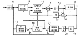
図2において、本発明の受信機は、レーク受信機11、通信路推定器10、記号間干渉低減装置12および等価モデル16を備える。ここで、レーク受信機11は通信路推定器10によって供給される通信路推定を使用し、記号間干渉低減装置12が後に続く。そしてこの記号間干渉低減装置12に伝送通信路の等価モデル16を接続する。干渉低減装置12は、インターリーブ演算の逆の演算を行う逆インターリーブ器14を介して、復号器15と接続する。さらに、推定器10により提供された通進路推定は、通信路等価モデルを決定するために通信路モデルに供給される。
In FIG. 2, the receiver of the present invention includes a
本発明において、記号間干渉低減装置12は、加重入力部および加重出力部を備える遅延判定帰還系列推定(DDFSE)型である。すなわち、記号レベルがそれぞれロジックレベル1とロジックレベルである確率p(1)とp(0)との比の対数ln [p(1)/p(0)]の形式を取る。同様に、復号器15もまた加重入力部および加重出力部を備える。
In the present invention, the intersymbol
多重路伝搬の場合、時間tでの拡散スペクトル受信機の入力部で受信された信号は、次: For multipath propagation, the signal received at the input of the spread spectrum receiver at time t is:

の形式をとり、ここで、 Where:
![]()
![]()
は、復調記号s(k)の波形であり、e(q)は拡散系列であり、Nは拡散率であり、g(t)は、ナイキストルートフィルタ6の伝達関数であり、TeおよびTsはそれぞれ「チップ」枠(pe’riodes dite “chip”)および記号枠(symbol de symbole)であり、Lは通信路の経路数であり、hl(t)およびτl(t)はそれぞれ複素振幅および第一番目経路の時間遅延であり、ω(t)は電力スペクトル密度N0のガウスの白色雑音である。 Is the waveform of the demodulated symbol s (k), e (q) is the spreading sequence, N is the spreading factor, g (t) is the transfer function of the Nyquist root filter 6, T e and T s is a “chip” frame (pe'riodes dite “chip”) and a symbol frame (symbol de symbole), L is the number of channels, and h l (t) and τ l (t) are respectively Complex amplitude and time delay of the first path, ω (t) is Gaussian white noise with power spectral density N 0 .
d(i)は伝送記号の積であり、拡散系列を掛け合わせると、c(i)s(〔i/n〕)であり、この〔〕は、「整数部分」関数を表す。受信信号はまた、以下: d (i) is a product of transmission symbols, and when multiplied by the spreading sequence, c (i) s ([i / n]), which represents an “integer part” function. The received signal is also the following:
![]()
![]()
の形式で書かれ、ここで、 Written here, where
ナイキストの定理に基づき、チップの周波数で2回受信信号r(t)をサンプリングし、スタックサンプル(e’chantillons empile’s)のベクトルr(i)を得る。このベクトルr(i)は、チップ記号_iを推定するために使用される。 Based on the Nyquist theorem, the received signal r (t) is sampled twice at the chip frequency to obtain a vector r (i) of stack samples (e'chantillons empile's). This vector r (i) is used to estimate the chip symbol _i.
ベクトルr(i)は次: The vector r (i) is:
の形式をとり、M1およびM2は、Teの倍数としてhi(t)の長さを表し、 Take the form, M 1 and M 2 represents the length of h i (t) as a multiple of T e,
拡散演算の逆の演算の後、ブランチ_j(伝送通信路の経路_j)の記号_kに対する低減記号(signal re’duit)は次: After the inverse of the spreading operation, the reduction symbol (signal re'duit) for symbol _k of branch _j (transmission channel path_j) is:
のように表され、dkは拡散配列と送信記号との産物であり、τji=(τj-τi)/Tcである。 Where d k is the product of the spreading sequence and the transmitted symbol, τ ji = (τ j −τ i ) / T c .
文献[11]で報告された結果を用いて、レーク受信機11の出力
Using the results reported in the literature [11], the output of the
![]()
![]()
が以下: Is the following:
のように表され、ここで、 Where, where
であり、gl(k)は、レーク受信機11の出力部における等価モデルの第一番目振幅であり、(2L’+1)は、等価モデル16のエコー数である。
G l (k) is the first amplitude of the equivalent model at the output of the
経路の遅延が、チップ枠Tcの倍数だけ間隔があくと仮定すると、等価モデル16のパラメーターは次の方程式:
Assuming that the path delays are spaced by a multiple of the chip frame T c , the parameters of the
で与えられる。 Given in.
図5の曲線は、理想的な場合(曲線C1)およびレーク受信機の出力部(曲線C2)における、信号/雑音に対するビット誤り伝送速度BERを示す。 The curve in FIG. 5 shows the bit error transmission rate BER versus signal / noise in the ideal case (curve C1) and at the output of the rake receiver (curve C2).
これらの曲線および図6の曲線は、拡散率4での模擬演算によって得られた。そして、4つの経路を有するEQ−4伝送通信路は、チップ枠によって分割されたそれぞれの遅延を有し、各経路は、環状の複雑なガウスの形状(forme gaussienne complexe circulaire)であるか、レーリー減衰している。出力符号は、予め符号化された系列cを産出する産出多項式{1,(1+D3+D4)/(1+D+D4)}および、比率1/2の16の状態を有する再帰的組織符号(code syste’matique re’cursif)である。この予め符号化された系列cは擬似ランダムインターリーブ器に送信され、フレームに分割される。 These curves and the curve of FIG. 6 were obtained by a simulation calculation with a diffusivity of 4. The EQ-4 transmission channel having four paths has respective delays divided by the chip frame, and each path has a ring-shaped complex Gaussian shape (forme gaussienne complexe circulaire) It is decaying. The output code has 16 states with a yield polynomial {1, (1 + D 3 + D 4 ) / (1 + D + D 4 )} yielding a pre-encoded sequence c and a ratio of 1/2. It is a recursive systematic code (code syste'matique re'cursif). This pre-encoded sequence c is transmitted to a pseudo-random interleaver and divided into frames.
曲線C1と曲線C2との比較は、この種類の受信機の性能が非常に低いことを示している。 Comparison of curve C1 and curve C2 shows that the performance of this type of receiver is very low.
文献[2]および[3]に推奨されるように、低拡散率のために生じる記号間干渉によって引き起こされた性能低下を抑えるために、LMMSE等化器をレーク受信機の上流(amont)に配置する場合、第i番目チップ記号の推定は次の形式: As recommended in Refs. [2] and [3], an LMMSE equalizer can be placed upstream of the rake receiver to reduce the performance degradation caused by intersymbol interference caused by low spreading factors. When placed, the estimation of the i th chip symbol is of the form:
をとり、σd 2はチップ系列の偏差である。 Σ d 2 is the deviation of the chip sequence.
この種類の等化器によって得られた性能を示す図5の曲線C3は、この解決策がレーク受信機の性能を有意に改善しないことを示している。 Curve C3 in FIG. 5, which shows the performance obtained with this type of equalizer, shows that this solution does not significantly improve the performance of the rake receiver.
本発明のレーク受信機11の性能を有意に改良するために、その出力部に、状態数削減のトレリスに基づく部分最適DDFSE検出器の周辺に設置された記号間干渉低減装置12を配置する。この種類の検出器は、通信路等価モデル16と接続している。
In order to significantly improve the performance of the
サンプルはDDFSE検出器に供給される前に、通信路等価モデル16に起因して遅延する。次いで、このサンプルは、
The sample is delayed due to the channel
として表され、ここでベクトル=_h1(k)=gl−L’(k)は、通信路係数[_h0(k),…,_h2L’(k)]Tのベクトルを表す。 Where vector = _h 1 (k) = g 1−L ′ (k) represents a vector of channel coefficients [_h 0 (k),..., _H 2L ′ (k)] T.
次いで、このDDFSE検出器は、最適化最大事後確率(MAP)基準をQ2L’状態の完全なトレリスに適用するBCJR技術と比較して、状態数削減のトレリスで作動する(文献[8]を参照)。ここで、Qは、PSK変調コンステレーションのポイント数であり、(2L’+1)は、通信路等価モデル16の経路数である。
The DDFSE detector then operates with a reduced number of states trellis compared to the BCJR technique, which applies an optimized maximum a posteriori (MAP) criterion to the full trellis in the Q2L 'state (see reference [8]). ). Here, Q is the number of points of the PSK modulation constellation, and (2L ′ + 1) is the number of paths of the communication path
この種類のトレリスは、実際、時間に分散し、状態間の遷移が処理状態にのみ依存する有限状態機械であり、各時点(instant)での状態数が一定である。このようなトレリスにおいて、セクションは2つの続いた時点に対応する状態間の全ての遷移を表す。 This type of trellis is actually a finite state machine that is dispersed in time and the transition between states depends only on the processing state, and the number of states at each instant is constant. In such a trellis, a section represents all transitions between states corresponding to two successive time points.
DDFSE検出器において、トレリスは、従ってQυrの状態数に削減される。ここで、υrは、減少記憶容量(me’moire re’duit)と呼ばれる正の整数であり、DDFSE検出器の場合、υr<2L’ように選択される。 In the DDFSE detector, the trellis is thus reduced to a number of states of Q υr . Here, the upsilon r, is a positive integer called the reduced storage capacity (me'moire re'duit), if the DDFSE detector, is selected so υ r <2L '.
トレリス入力系列a1 nは、a1 nが部分文字列(sous-chai’ne)s=an−υr+1 nで終了する場合、一般的に基板(sous-e’tat)_sで終了すると言われている。υr=2L’の場合、深さ_nでは、基板空間(sous-e’tats)Snは、BCJRの状態の完全な空間Snと一致する。υr<2L’の場合、Snは、全ての状態から誘導された可能な基板_sの全てを含む下位集合に低減される: Trellis input sequence a 1 n, when a 1 n ends with substring (sous-chai'ne) s = a n-υr + 1 n, Generally ends with the substrate (sous-e'tat) _s words It has been broken. For upsilon r = 2L ', the depth _n, board space (sous-e'tats) S n is consistent with complete space S n states BCJR. For υ r <2L ', S n is reduced to a subset containing all possible substrates _s derived from all the states:
![]()
![]()
上記方程式に使用された記号は、DDFSEアルゴリズムが適用されるサブトレリスT(S,B)の定義に当てはまる。 The symbols used in the above equation apply to the definition of subtrellis T (S, B) to which the DDFSE algorithm is applied.
各時点において、全ての遷移に対して、ブランチメトリック演算(calcul de me’trique de branche)は、すでに推定された2L’+1の系列の離散時間型通信路におけるインパルス応答の変換を意味する。この系列に対して推測された最初のυr+1記号は、処理されている遷移で、および遷移と連結した開始サブトレリス基板で得られる。 At each point in time, for all transitions, the branch metric calculation means the transformation of the impulse response in the already estimated 2L ′ + 1 series of discrete-time channels. The first υ r +1 symbol guessed for this sequence is obtained at the transition being processed and at the starting subtrellis substrate concatenated with the transition.
それぞれの時間性インデックスn∈[1,τ]において、全てのビット指数j∈[1,q]に対して、記号BCJRアルゴリズムによる最適記号は、次の方程式: For each bit index jε [1, q] at each temporal index nε [1, τ], the optimal symbol according to the symbol BCJR algorithm is the following equation:
に基づいて事後確率比の対数を与える。ここで、h’は、(最低相(phase minimale)への変換が可能な場合)通信路係数の横ベクトルの推定(または再推定)であり、y1 τは長さτの測定系列(se’quence observe’e)である。次の誘導では、h’による調整は当然のことであり、表現を簡潔にするために削除される。 Gives the logarithm of the posterior probability ratio based on. Here, h ′ is an estimation (or re-estimation) of the horizontal coefficient of the channel coefficient (when conversion to the phase minimale is possible), and y 1 τ is a measurement sequence of length τ (se 'quence observe'e). In the next derivation, the adjustment by h ′ is natural and is deleted for the sake of brevity.
印を付けた(marque’s)ビット入力記号系列に周辺化(marginalisation)が行われる場合、方程式(21)は次の形式: When marginalization is performed on a marque ’s bit input symbol sequence, equation (21) has the following form:
で再び書かれ、次のMin−Log-BCJR概算: Rewritten in the following Min-Log-BCJR approximation:
を行う。ここで、Δkは非負量を表し、事後確率比の対数λ(an,j)は、次の方程式: I do. Where Δk represents a non-negative quantity, and the logarithm λ (a n, j ) of the posterior probability ratio is:
![]()
![]()
を用いて評価され、{−lnp(a1 τ,y1 τ)}は、入力系列a1 nおよび受信系列y1 nに関する、トレリスの経路の、雑音に対するメトリックコスト(metric cost)を表す。トレリスの削減に起因して、DDFSE装置12は、1つの接点当たりたった1つのサバイバーしか選択しないことに存する「パーサバイバー」PSPアルゴリズムに基づいた部分最適の様式で、部分最適量{−lnp(a1 τ,y1 τ)}を評価する。所定のサブトレリスT(S,B)および特定のメトリックブランチに対して、表現μn ⇔(b)は、(系列の末尾の記号を考慮して)深さ0の基板0で始まり、深さτの基板0で終わり、セクション_nのブランチb∈Bnを通過する、最良の経路のメトリックコストを与える。各ブランチb∈Bnが3つのフィールド(始動基板フィールドb−∈Bn、終着基板フィールドb+∈Bn、およびb∇={b1 ∇,…,bq ∇}標識化フィールド)を含み、時点nでの時間の関数として変化するレベル1の記号間干渉たたみ込み符号に対してビット標識入力記号をモデリングすることがまた想定される。DDFSE装置12の出力は、以下:
{−lnp (a 1 τ , y 1 τ )} represents the metric cost to noise of the trellis path for the input sequence a 1 n and the received sequence y 1 n . Due to the trellis reduction, the
![]()
![]()
のように表される。 It is expressed as
次の方程式で表されるメトリックコストμn ⇔(b)は常に、合計で3つの項に分解され、 The metric cost μ n ⇔ (b) expressed by the following equation is always decomposed into a total of three terms:
![]()
![]()
μn →(s)は、基板0∈S0から始まり、基板s∈Snで終わる最良の下位経路の蓄積順方向メトリックを表し、次の方程式: μ n → (s) represents the accumulation forward metric of the best sub-path starting with substrate 0εS 0 and ending with substrate sεS n , and the following equation:
![]()
![]()
を用いて再帰的に演算され、この方程式は、次の限界状態: This equation is computed recursively using the following limit states:
![]()
![]()
を有する。ここで、μn ←(s)は、基板s∈S0から始まり、基板0∈Sτで終わる最良の下位経路の蓄積順方向メトリックを表し、次の方程式: Have Here, μ n ← (s) represents the accumulation forward metric of the best lower path starting with substrate sεS 0 and ending with substrate 0εS τ , and has the following equation:
![]()
![]()
を用いて再帰的に演算され、この方程式は、次の限界状態: This equation is computed recursively using the following limit states:
![]()
![]()
を有する。 Have
DDFSE装置12によって使用されるPSPアルゴリズムに基づくブランチメトリックξn(b)は、以下:
The branch metric ξ n (b) based on the PSP algorithm used by the
のように表される。 It is expressed as
上記の等式において、時間_nで記号間干渉符号を貫通する復号記号Snは、ブランチ標識b∇の再定義から単純に得られる。記号{sn−υr,…,sn−1}の復号系列は基板b−から簡単に演繹されるが、記号{s’n−2L’,…,s’n−υr−1}の推定系列は、b−で終わり、b−を構成するブランチの標識を再定義する「サバイバー」経路に沿って逆方向に移動することによって得られる。「サバイバー」経路は、深さ2L’の滑りトレースバック行列(matrice glissante de remonte’e)に記憶されると想定される。 In the above equation, the decoded symbol S n that penetrates the intersymbol interference code at time_n is simply obtained from the redefinition of the branch beacon b ∇ . The decoding sequence of the symbols {s n−υr ,..., S n−1 } is simply deduced from the substrate b−, but the estimation of the symbols {s ′ n−2L ′ ,..., S ′ n−υr−1 } sequence, b - end with, b - is obtained by moving in opposite directions along the "survivor" path to redefine the labeling of branches constituting the. The “survivor” path is assumed to be stored in a matrice glissante de remonte'e with a depth of 2L ′.
この解決策の実施を示す図5の曲線C4は、4つの状態のDDFSE削減トレリス複雑さ(υr=1)を用いて得られた。この曲線は、たとえ低いインターリーブ係数(=4)で、著しく削減された状態数のトレリスであっても、この解決策は、理想的な解決策、特に、複雑さのためにCDMA技術に適用されない最尤系系列推定(MLSE)型通信路推定を用いたC5によって示される解決策を概算する。 Curve C4 of FIG. 5 illustrating the implementation of this solution was obtained using a four-state DDFSE reduced trellis complexity (ν r = 1). Even though this curve is a trellis with a significantly reduced number of states, even with a low interleave factor (= 4), this solution does not apply to ideal solutions, especially CDMA technology due to complexity Approximate the solution indicated by C5 using maximum likelihood sequence estimation (MLSE) type channel estimation.
図3に示されるように、この種類の受信機の性能をさらに向上させるために、本発明は、装置12の出力部を、出力部が逆インターリーブ器14に接続している比較器13のプラス入力部に接続することを提案する。逆インターリーブ器14の出力部は、復号器15からの符号化ビットの固有(intrinse’que)確率比の対数を受信する入力部に接続される。この復号器15は、第一出力で事後確率比の対数を伝送されたデータビットに供給し、第二出力で事後確率比を符号化ビットに供給する。そして、この符号化ビットは、誤り訂正の後に復号データビットに供給された復号の逆の操作によって測定される。復号器15の第二出力は、比較器18および逆インターリーブ器17を介して、比較器13のマイナス入力部およびDDFSE装置12の入力部にループされる。逆インターリーブ器14の出力はまた、比較器18のマイナス入力部に供給される。
As shown in FIG. 3, in order to further improve the performance of this type of receiver, the present invention adds the output of the
復号器15は、BCJRアルゴリズムを用いて最適に通信路符号を復号することができる。干渉低減装置12は、系列a1 τを構成する記号anのビットan,jの値の事後確率比を送達する。この送達は、(第一の反復が0値である)復号器から送信されたビットan,jの値の事前確率比の対数を用いて、時点nにおける通信路係数の(等価)ベクトルの受信系列y1 τおよび推定(または再評価)値h’(n)を考慮して行われる。
The
ビットλ’(an,j)に概算された事後確率比は、次の等式:
λ’(an,j)=λa(an,j)+λe(an,j) (32)
を用いて2つの部分に分割される。
The approximate posterior probability ratio for bits λ ′ (a n, j ) is the following equation:
λ ′ (a n, j ) = λ a (a n, j ) + λ e (a n, j ) (32)
Is divided into two parts.
逆インターリーブ器14による逆インターリーブの後、固有確率比対数の完全な系列は、符号化記号のビットに適用される固有確率比対数系列となり、復号器15に供給される。同様に、復号器15の出力部において、符号化ビットに適用される固有確率比対数λ(Cn,j)は、事前部分および固有部分に分解される。後者は、事前比に対する対数λ(Cn,j)から、復号器の出力における事前比の対数λa(Cn,j)を、比較器でビットごとに減算することによって演算される:
λe(cn,j)=λ(cn,j)−λa(cn,j) (33)。
After deinterleaving by the
λ e (c n, j ) = λ (c n, j ) −λ a (c n, j ) (33).
復号器15の出力部の符号化ビットに適用される固有確率比対数の系列は、インターリーブ器17によって再びインターリーブされ、記号ビットに適用される事前確率比対数のN系列の次の検出後に復号器15に戻される。特定の回数このプロセスを反復することによって、受信された系列のデータビットに対する信号/雑音比の著しい増加が得られる。
The sequence of inherent probability ratio logarithms applied to the coded bits at the output of the
図3に示される受信機にもたらされるように、非常に規則正しいビタビ構造および中程度の複雑性による良好な性能のため、装置12のDDFSE検出器はターボ検出に完全に適していると思われる。
Due to the very regular Viterbi structure and good performance due to moderate complexity, as provided for the receiver shown in FIG. 3, the DDFSE detector of
この第一の反復において、図3に示されるシステムは、図2に記載されるのと全く同様に作動する。第二およびその後の反復で、DDFSE装置12により使用されるブランチメトリックξn(b)を与える等式(31)はさらなる項:
In this first iteration, the system shown in FIG. 3 operates exactly as described in FIG. In the second and subsequent iterations, equation (31) giving the branch metric ξ n (b) used by the
を有する。この等式は、再帰的順方向処理の間に一度だけ演算され、次いで、記憶装置に保存される。 Have This equation is computed only once during recursive forward processing and then stored in storage.
等式(31)のブランチb∈Bnにおける事前確率対数: Prior probability logarithm in branch bεB n of equation (31):
![]()
![]()
は、当該ブランチが保持する標識b∇の事前確率対数に完全に一致する。従って、 Completely matches the prior probability logarithm of the sign b が held by the branch. Therefore,
![]()
![]()
符号C0からの固有確率比対数の系列を再インターリーブした後、記号ビットan,jの事前確率対数の間に完全な逆訂正が行われると仮定した場合、 If it is assumed that after re-interleaving the sequence of logarithm probability logarithms from the code C 0 , a complete inverse correction is performed between the prior probability logarithms of the symbol bits a n, j :
が得られる。 Is obtained.
最後に、等式(25)および(36)を用いて、記号an,jに適用されるDDFSE装置12の出力λ’(an,j)が、合計2つの対数の項に分解される:
λ’(an,j)=λa(an,j)+λ’e(an,j) (37)
ここで、
Finally, using equations (25) and (36), the output λ ′ (a n, j ) of
λ ′ (a n, j ) = λ a (a n, j ) + λ ′ e (a n, j ) (37)
here,
![]()
![]()
は、復号器15に供給されるビットan,jに適用される事前比の対数を表し、ここで、
Represents the logarithm of the prior ratio applied to the bits a n, j supplied to the
であり、ここで、 And where
であり、この等式の第二項は、復号工程を通して系列a1 τのビット標識を有する記号の他のビット全てから得られるビットan,jの固有確率比の対数を表す。 And the second term of this equation represents the logarithm of the inherent probability ratio of bits a n, j obtained from all other bits of the symbol having the bit indicator of the sequence a 1 τ through the decoding process.
υr=2L’の場合、DDFSE装置12により実施されるアルゴリズムは、通信路トレリス全体に適用されるMin−Log−BCJRアルゴリズムに形式的に等しい。処理が削減された状態数のトレリスのみに適用される場合、経路の履歴から得られ、ブランチメトリックの誘導に関与する推定系列は、可能性のある誤り伝搬の効果のため、その性能を低下させる。にもかかわらず、レーク受信機11の出力部における等価通信路は、DDFSE低減装置12の構造に、任意の重要な誤り伝搬を誘導しない。その結果として、選択υr=1はほとんどの事例に十分である。
For υ r = 2L ′, the algorithm implemented by the
パイロット記号の系列に適用される訂正および平均演算処理によって得られる従来の通信路推定の性能は、記号間干渉に起因した低拡散値によって低下する。 The performance of the conventional channel estimation obtained by the correction and averaging processing applied to the pilot symbol sequence is degraded by the low spreading value caused by intersymbol interference.
これを例証するために、図6は、異なる解決策によって得られる復号器15の出力部の信号/雑音に対するビット誤り率の曲線を示す。この図において、曲線C6は理想的状態に該当する。従来の通信路推定が使用される状態に該当する曲線C7は、この解決策が、理想から比較的遠い、比較的低い性能を与えることを示している。
To illustrate this, FIG. 6 shows a bit error rate curve versus signal / noise at the output of the
本発明は、記号間干渉の公知の構造を用いて図2〜4に示されたシステムにおいて、通信路推定の性能を向上させることを提案する。この目的を達成するために、図7に示された通信路推定器10を使用する。この通信路推定器は、最小平均二乗誤差(MMSE)法または最小二乗(LS)法を用いて、出力部が通信路推定訂正器13に接続されている従来の通信路推定器30を備え、装置12および通信路モデリング装置16によって使用される通信路推定を送達する。
The present invention proposes to improve the performance of channel estimation in the systems shown in FIGS. 2-4 using the known structure of intersymbol interference. In order to achieve this object, the
従来の通信路推定器の1つの例が、例えば参考文献[1]に記載されている。 One example of a conventional channel estimator is described in, for example, reference [1].
経路の遅延は、チップ枠Tcの倍数だけ間隔があき、遅延の拡散が記号枠Tsより小さいと仮定すると、従来の通信路推定は以下の方程式を用いて得られる: Assuming that the path delays are spaced apart by multiples of the chip frame T c and the delay spread is smaller than the symbol frame T s , conventional channel estimation is obtained using the following equation:
ここで、_pは、パイロット系列の記号数であり、 Where _p is the number of symbols in the pilot sequence,
![]()
![]()
は、完全な(雑音のない)通信路係数であり、 Is the perfect (no noise) channel coefficient,
![]()
![]()
は、N0/Epilotに等しい偏差を有すると考えられる通信路雑音推定であり、Epilotはパイロット記号エネルギーである。MMSE通信路推定は、次の式: Is a channel noise estimate that is considered to have a deviation equal to N 0 / E pilot , where E pilot is the pilot symbol energy. The MMSE channel estimation is:
を用いて従来の通信路推定から演繹される。 Is deduced from the conventional channel estimation.
等式(18)を用いると、 Using equation (18),
に演繹され、ここで、MHは行列Mの共役転置行列である。 Where M H is the conjugate transpose of the matrix M.
推定はまた、LS法を用いて達成される: Estimation is also achieved using the LS method:
![]()
![]()
しかし、この推定装置は、雑音電力を考慮せず、従ってMMSE推定と比較して信号/雑音に関する性能を低下させる。図6で明らかなように、パイロット記号での訂正のみに基づく従来の通信路推定は、低拡散係数(曲線C7)の低い性能の導くことが模擬計算によって示された。MMSE法およびLS法を用いることが可能である、記号間干渉の構造が考慮されなければならない。MMSE法を用いて達成される性能が図6の曲線C9によって示され、従来の装置を超えた有意な改良を示唆している。 However, this estimator does not take into account noise power and therefore degrades signal / noise performance compared to MMSE estimation. As is clear from FIG. 6, it has been shown by simulation calculations that the conventional channel estimation based only on correction with pilot symbols leads to low performance with a low diffusion coefficient (curve C7). The structure of intersymbol interference, which can use MMSE and LS methods, must be considered. The performance achieved using the MMSE method is shown by curve C9 in FIG. 6, suggesting a significant improvement over conventional devices.
図4に示された本発明の有利な改良型において、本発明の受信機は、通信路再推定を達成するための反復検出ループを備える。当該ループは、復号器15の出力部に接続されたインターリーブ器を備え、該復号器15の出力部は、閾値比較器20を介して反復通信路推定装置21に接続されている。比較器20は、復号器15の加重またはフレキシブル出力を、加重値が所定の閾値より大きいか否かによって「ハード」の出力(0または1)に変換する。
In an advantageous refinement of the invention shown in FIG. 4, the receiver of the invention comprises an iterative detection loop for achieving channel re-estimation. The loop includes an interleaver connected to the output unit of the
さらに、レーク受信機11の入力部に供給される信号は、反復通信路推定装置21および、パイロット系列を用いて第一通信経路推定を達成するために使用される通信路推定装置10にも供給される。これらの装置は、それぞれのスイッチ23,24を用いて通信路推定を、DDFSE装置12の入力部に供給される等価進路推定モデルを決定するように設計された通信路モデリング装置16に供給する。
Furthermore, the signal supplied to the input of the
受信機は、パイロット記号を用いて装置10によって決定され、通信路モデリング装置16に供給される通信路推定を基に、最初の復号を行う(スイッチ23:閉、スイッチ24:開)。次いで、通信路復号器15からの推定符号は、装置21によって使用されて通信路の再推定を行い、次の反復のために通信路推定雑音を低減する。このようにして決定された通信路推定は、モデリング装置16に供給される(スイッチ23:開、スイッチ24:閉)。
The receiver performs initial decoding based on the channel estimation determined by the
もちろん図4に示された反復通信路推定プロセスはまた、図2に示されたシステム、すなわち図3に示された反復検出ループを含まない受信機に適用される。 Of course, the iterative channel estimation process shown in FIG. 4 also applies to the system shown in FIG. 2, ie, a receiver that does not include the iterative detection loop shown in FIG.
図6の曲線C8およびC10は、反復通信路推定法を用いる図4に示された解決策を用いて達成された性能を示し、曲線C8は、従来の通信路推定器は使用される状態に該当し、曲線C10は、MMSE訂正を用いた通信路推定器に該当する。この方法が性能を向上させ、MMSE訂正を用いた通信路推定の場合、曲線C6に示されるように理想的な状態を概算することが、これらの2つの曲線によって示された。 Curves C8 and C10 in FIG. 6 show the performance achieved using the solution shown in FIG. 4 using the iterative channel estimation method, and curve C8 shows that the conventional channel estimator is in use. Corresponding, curve C10 corresponds to a channel estimator using MMSE correction. It has been shown by these two curves that this method improves performance and, in the case of channel estimation using MMSE correction, approximates the ideal state as shown by curve C6.
Claims (10)
上記方法が、
上記多重路伝送通信路を介して伝送された受信信号に基づき、上記通信路推定値を用いて送信信号を再構築する工程と、
伝送通信路の等価モデルを、上記通信路推定値から決定する工程と、
上記伝送通信路の等価モデル、および、状態数が削減されたトレリスに基くDDFSE検出器であって、受信した符号化記号の推定値を出力するDDFSE検出器を用いて、再構築された上記送信信号における低拡散率に起因する記号間干渉を低減する工程と、
上記DDFSE検出器から出力された上記符号化記号を逆インターリーブする工程と、
逆インターリーブされた上記符号化記号の推定値を復号し、送信された上記データ記号を再構築する工程と、を含んでいることを特徴とする方法。 Using spread spectrum techniques of spreading factor 16 or lower spreading factor, a method of receiving a signal transmitted to the multipath transmission channel, the signal is multiplied by the spreading sequence, and the predetermined pilot symbols sent in sequence in the form of binary coded symbols comprising data symbols, comprising the step of the method determines the channel estimate using received predetermined pilot symbols,
The above method is
Based on the received signal transmitted through the multipath transmission channel, a step of reconstructing a transmit signal by using the channel estimates,
The equivalent model of the heat transmission channel, and determining from said channel estimates,
The transmission reconstructed using a DDFSE detector based on an equivalent model of the transmission channel and a trellis with a reduced number of states, which outputs an estimate of the received encoded symbol Reducing intersymbol interference due to low spreading factor in the signal;
Deinterleaving the encoded symbols output from the DDFSE detector ;
Decodes the deinterleaved estimate of the encoded symbols, wherein the containing a step of reconstructing the data symbols sent, the.
再推定された上記符号化記号がインターリーブされ、
通信路推定値が、再推定されインターリーブされた上記符号化記号を基に得られ、
伝送通信路の等価モデルが上記通信路推定値から決定され、
反復nで決定された上記通信路推定値および伝送通信路の上記等価モデルがそれぞれ、次の反復n+1において、送信信号を再構築するために、および記号間干渉を低減するために使用される反復プロセスにおいて、上記通信路推定値が決定されることを特徴とする、請求項1〜5のいずれか1つに記載の方法。 Deinterleaved coded symbols obtained by iteration n is re estimated during decoding as a function of the obtained data symbols after the decoding and error correction,
The encoding symbols that are re-estimated interleaved,
Shin path estimated value passed is obtained based on the coded symbols are interleaved be re-estimated,
Equivalent model of the transmission channel is determined from the channel estimates,
Each said equivalent model of the channel estimate and the transmission channel determined by iteration n is in the next iteration n + 1, in order to reconstruct the transmitted signal, in order to reduce the inter-and Symbol Interference The method according to claim 1, wherein the channel estimate is determined in an iterative process used.
上記システムはさらに、
上記通信路推定値の関数として伝送通信路の等価モデルを決定するための通信路モデリング装置(16)と、
状態数が削減されたトレリスに基づくDDFSE検出器であって、上記伝送通信路の等価モデルを用いて記号間干渉を低減し、受信した符号化記号の推定値を出力するDDFSE検出器を含む、再構築された送信信号における記号間干渉を低減するための低減装置(12)と、
上記DDFSE検出器から出力された上記符号化記号の推定値を逆インターリーブする逆インターリーブ装置(14)と、
逆インターリーブされた上記符号化記号の推定値を復号し、送信された上記データ記号を供給する復号装置(15)と、を備えていることを特徴とするシステム。 Using spread spectrum technology spreading factor 16 or lower spreading factor, a system for receiving signals transmitted to the multipath transmission channel, the signal is multiplied by the spreading sequence, predetermined Transmitted in the form of a sequence of binary symbols including a pilot symbol and a data symbol , and the system transmits a transmission signal using a channel estimation value based on a received signal transmitted via the multipath transmission channel. the reconstruction and to rake receiver (11), the channel estimates based on received pilot symbols, above rake receiver (11) and passes the channel estimates channel estimation device and (10) Prepared,
The system further includes
Channel modeling device for determining the equivalent model of the transmission channel as a function of the channel estimation value (16),
A DDFSE detector based on a trellis with a reduced number of states, including a DDFSE detector that reduces intersymbol interference using an equivalent model of the transmission channel and outputs an estimate of a received encoded symbol; A reduction device (12) for reducing intersymbol interference in the reconstructed transmission signal;
A deinterleaving device (14) for deinterleaving the estimated value of the coded symbol output from the DDFSE detector ;
System decodes the deinterleaved estimate of the encoded symbols, decodes device for supplying the data symbol is transmitted (15), characterized in that it comprises a.
該再推定された符号化記号から上記推定され逆インターリーブされた符号化記号を減算し、外因性の再推定された符号化記号の系列を得る第一減算装置(18)と、
該外因性の再推定された符号化記号の系列をインターリーブする第一インターリーブ装置(17)と、
次の反復で低減装置(11)によって受信され推定された記号の系列から、外因性の再推定された符号化記号の該系列を減算する第二減算装置(13)と、をさらに備えている、請求項7または請求項8に記載の受信システム。 An apparatus (15) for re-estimating the encoded symbols as a function of decoded data symbols after error correction;
A first subtractor (18) for subtracting the estimated and deinterleaved encoded symbols from the re-estimated encoded symbols to obtain a sequence of extrinsic re-estimated encoded symbols;
A first interleaving device (17) for interleaving the extrinsic re-estimated sequence of encoded symbols;
From the following series of iterations is received by a reduction device (11) estimated symbol further comprises a second subtractor for subtracting the said system column exogenous re-estimated coded symbols (13), the The receiving system according to claim 7 or 8.
等価通信路モデルを決定する装置(16)およびレーク受信機(11)に、再推定された符号化記号のインターリーブ化系列に基づいた伝送通信路推定を供給する第二通信路推定装置(21)と、をさらに備えている、請求項7〜9のいずれか1つに記載の受信システム。 A second interleaving device (19) for interleaving the sequence of re-estimated encoded symbols at the output of the decoding device (15);
Second channel estimation device (21) for supplying a channel estimation based on an interleaved sequence of re-estimated coded symbols to a device (16) for determining an equivalent channel model and a rake receiver (11). When, further comprising a receiving system according to any one of claims 7-9.
Applications Claiming Priority (2)
| Application Number | Priority Date | Filing Date | Title |
|---|---|---|---|
| FR0111549A FR2829326A1 (en) | 2001-09-06 | 2001-09-06 | SUB-OPTIMAL ITERATIVE RECEPTION PROCESS AND SYSTEM FOR CDMA HIGH SPEED TRANSMISSION SYSTEM |
| PCT/FR2002/002848 WO2003021805A1 (en) | 2001-09-06 | 2002-08-09 | Sub-optimal iterative receiver method and system for a high-bit-rate cdma transmission system |
Publications (2)
| Publication Number | Publication Date |
|---|---|
| JP2005502260A JP2005502260A (en) | 2005-01-20 |
| JP3889400B2 true JP3889400B2 (en) | 2007-03-07 |
Family
ID=8867035
Family Applications (1)
| Application Number | Title | Priority Date | Filing Date |
|---|---|---|---|
| JP2003526018A Expired - Lifetime JP3889400B2 (en) | 2001-09-06 | 2002-08-09 | Suboptimal iterative receiver method and system for high bit rate CDMA transmission systems |
Country Status (9)
| Country | Link |
|---|---|
| US (1) | US7298778B2 (en) |
| EP (1) | EP1423921B1 (en) |
| JP (1) | JP3889400B2 (en) |
| CN (1) | CN1319286C (en) |
| AT (1) | ATE299623T1 (en) |
| DE (1) | DE60205029T2 (en) |
| ES (1) | ES2246414T3 (en) |
| FR (1) | FR2829326A1 (en) |
| WO (1) | WO2003021805A1 (en) |
Families Citing this family (27)
| Publication number | Priority date | Publication date | Assignee | Title |
|---|---|---|---|---|
| US8194770B2 (en) | 2002-08-27 | 2012-06-05 | Qualcomm Incorporated | Coded MIMO systems with selective channel inversion applied per eigenmode |
| US7324429B2 (en) | 2002-10-25 | 2008-01-29 | Qualcomm, Incorporated | Multi-mode terminal in a wireless MIMO system |
| US8134976B2 (en) | 2002-10-25 | 2012-03-13 | Qualcomm Incorporated | Channel calibration for a time division duplexed communication system |
| US8170513B2 (en) | 2002-10-25 | 2012-05-01 | Qualcomm Incorporated | Data detection and demodulation for wireless communication systems |
| US7151809B2 (en) * | 2002-10-25 | 2006-12-19 | Qualcomm, Incorporated | Channel estimation and spatial processing for TDD MIMO systems |
| US8208364B2 (en) | 2002-10-25 | 2012-06-26 | Qualcomm Incorporated | MIMO system with multiple spatial multiplexing modes |
| US8570988B2 (en) | 2002-10-25 | 2013-10-29 | Qualcomm Incorporated | Channel calibration for a time division duplexed communication system |
| US8169944B2 (en) | 2002-10-25 | 2012-05-01 | Qualcomm Incorporated | Random access for wireless multiple-access communication systems |
| US8320301B2 (en) | 2002-10-25 | 2012-11-27 | Qualcomm Incorporated | MIMO WLAN system |
| US7002900B2 (en) | 2002-10-25 | 2006-02-21 | Qualcomm Incorporated | Transmit diversity processing for a multi-antenna communication system |
| US8218609B2 (en) | 2002-10-25 | 2012-07-10 | Qualcomm Incorporated | Closed-loop rate control for a multi-channel communication system |
| US7986742B2 (en) | 2002-10-25 | 2011-07-26 | Qualcomm Incorporated | Pilots for MIMO communication system |
| US20040081131A1 (en) | 2002-10-25 | 2004-04-29 | Walton Jay Rod | OFDM communication system with multiple OFDM symbol sizes |
| US9473269B2 (en) | 2003-12-01 | 2016-10-18 | Qualcomm Incorporated | Method and apparatus for providing an efficient control channel structure in a wireless communication system |
| US7443909B2 (en) * | 2004-12-21 | 2008-10-28 | Nokia Corporation | Weighted autocorrelation method for downlink CDMA LMMSE equalizers |
| US8019032B2 (en) * | 2005-02-04 | 2011-09-13 | Qualcomm Incorporated | Method and system for channel equalization |
| CA2597593C (en) * | 2005-02-14 | 2010-07-27 | Viasat, Inc. | Integrated fec decoding and iterative diversity reception |
| US7466749B2 (en) | 2005-05-12 | 2008-12-16 | Qualcomm Incorporated | Rate selection with margin sharing |
| US8358714B2 (en) | 2005-06-16 | 2013-01-22 | Qualcomm Incorporated | Coding and modulation for multiple data streams in a communication system |
| US7602838B2 (en) * | 2005-12-22 | 2009-10-13 | Telefonaktiebolaget Lm Ericsson (Publ) | Linear turbo equalization using despread values |
| KR100816032B1 (en) * | 2007-02-13 | 2008-03-24 | 삼성전자주식회사 | Method of data transmission with iterative multi-user detection, and aparatus using the same |
| CN101540043B (en) * | 2009-04-30 | 2012-05-23 | 南京理工大学 | Analysis iteration fast frequency spectrum extrapolation method for single image restoration |
| EP2710771B1 (en) * | 2011-05-19 | 2017-08-16 | Telefonaktiebolaget LM Ericsson (publ) | Inter symbol interference reduction by applying turbo equalization mode |
| EP2807777B1 (en) * | 2013-04-04 | 2016-01-20 | Huawei Technologies Co., Ltd. | Methods and nodes in a wireless communication network for joint iterative detection/estimation |
| KR102381442B1 (en) * | 2015-01-23 | 2022-04-01 | 삼성전자주식회사 | Scheme for blind detecting transmission mode for interference cancellation |
| US10333561B2 (en) | 2015-01-26 | 2019-06-25 | Northrop Grumman Systems Corporation | Iterative equalization using non-linear models in a soft-input soft-output trellis |
| US10193659B2 (en) * | 2015-11-27 | 2019-01-29 | Cohda Wireless Pty Ltd. | Wireless receiver |
Family Cites Families (20)
| Publication number | Priority date | Publication date | Assignee | Title |
|---|---|---|---|---|
| JP3013763B2 (en) * | 1995-08-25 | 2000-02-28 | 日本電気株式会社 | Carrier synchronization unit |
| US5809086A (en) * | 1996-03-20 | 1998-09-15 | Lucent Technologies Inc. | Intelligent timing recovery for a broadband adaptive equalizer |
| US6097763A (en) * | 1997-10-31 | 2000-08-01 | Pairgain Technologies, Inc. | MMSE equalizers for DMT systems with cross talk |
| JP3441636B2 (en) * | 1997-11-21 | 2003-09-02 | 株式会社エヌ・ティ・ティ・ドコモ | Apparatus and method for determining channel estimation value, receiving apparatus, and transmission system |
| US6724844B1 (en) * | 1998-06-30 | 2004-04-20 | Koninklijke Philips Electronics N.V. | Method and device for improving DFE performance in a trellis-coded system |
| US6381271B1 (en) * | 1998-08-17 | 2002-04-30 | Telefonaktiebolaget Lm Ericsson (Publ) | Low complexity decision feedback sequence estimation |
| US6373888B1 (en) * | 1998-10-09 | 2002-04-16 | Telefonaktiebolaget Lm Ericsson (Publ) | Estimated channel with variable number of taps |
| JP3391373B2 (en) * | 1998-10-13 | 2003-03-31 | 日本電気株式会社 | Adaptive equalizer |
| WO2000044108A1 (en) * | 1999-01-22 | 2000-07-27 | Mitsubishi Denki Kabushiki Kaisha | Adaptive equalizer and adaptive equalizing method |
| US6556634B1 (en) * | 1999-02-10 | 2003-04-29 | Ericsson, Inc. | Maximum likelihood rake receiver for use in a code division, multiple access wireless communication system |
| US6721293B1 (en) * | 1999-03-10 | 2004-04-13 | Nokia Corporation | Unsupervised adaptive chip separation filter for CDMA terminal |
| US6426973B1 (en) * | 1999-04-29 | 2002-07-30 | The Board Of Trustees Of The University Of Illinois | Differential minimum mean squared error communication signal compensation method |
| JP2001111462A (en) * | 1999-10-06 | 2001-04-20 | Nec Corp | Delay judgment feedback type series estimation diversity receiver |
| US6377636B1 (en) * | 1999-11-02 | 2002-04-23 | Iospan Wirless, Inc. | Method and wireless communications system using coordinated transmission and training for interference mitigation |
| US6690739B1 (en) * | 2000-01-14 | 2004-02-10 | Shou Yee Mui | Method for intersymbol interference compensation |
| US6658071B1 (en) * | 2000-02-14 | 2003-12-02 | Ericsson Inc. | Delayed decision feedback log-map equalizer |
| FR2809249B1 (en) * | 2000-05-16 | 2004-04-23 | France Telecom | METHOD AND SYSTEM FOR ITERATIVE DETECTION AND DECODING OF RECEIVED SYMBOLS, COUPLED TO A REESTIMATION OF THE TRANSMISSION CHANNEL COEFFICIENTS |
| FR2813464B1 (en) * | 2000-08-29 | 2006-07-07 | Mitsubishi Electric Inf Tech | MULTI-USER DETECTION METHOD |
| US6975672B2 (en) * | 2001-01-08 | 2005-12-13 | Ericsson Inc. | Apparatus and methods for intersymbol interference compensation in spread spectrum communications |
| US6643646B2 (en) * | 2001-03-01 | 2003-11-04 | Hitachi, Ltd. | Analysis of massive data accumulations using patient rule induction method and on-line analytical processing |
-
2001
- 2001-09-06 FR FR0111549A patent/FR2829326A1/en active Pending
-
2002
- 2002-08-09 US US10/488,827 patent/US7298778B2/en not_active Expired - Lifetime
- 2002-08-09 AT AT02779631T patent/ATE299623T1/en not_active IP Right Cessation
- 2002-08-09 JP JP2003526018A patent/JP3889400B2/en not_active Expired - Lifetime
- 2002-08-09 ES ES02779631T patent/ES2246414T3/en not_active Expired - Lifetime
- 2002-08-09 DE DE60205029T patent/DE60205029T2/en not_active Expired - Lifetime
- 2002-08-09 CN CNB028174313A patent/CN1319286C/en not_active Expired - Lifetime
- 2002-08-09 EP EP02779631A patent/EP1423921B1/en not_active Expired - Lifetime
- 2002-08-09 WO PCT/FR2002/002848 patent/WO2003021805A1/en active IP Right Grant
Also Published As
| Publication number | Publication date |
|---|---|
| US20050013348A1 (en) | 2005-01-20 |
| CN1552129A (en) | 2004-12-01 |
| FR2829326A1 (en) | 2003-03-07 |
| EP1423921A1 (en) | 2004-06-02 |
| DE60205029D1 (en) | 2005-08-18 |
| EP1423921B1 (en) | 2005-07-13 |
| WO2003021805A1 (en) | 2003-03-13 |
| CN1319286C (en) | 2007-05-30 |
| JP2005502260A (en) | 2005-01-20 |
| DE60205029T2 (en) | 2006-04-20 |
| ES2246414T3 (en) | 2006-02-16 |
| US7298778B2 (en) | 2007-11-20 |
| ATE299623T1 (en) | 2005-07-15 |
Similar Documents
| Publication | Publication Date | Title |
|---|---|---|
| JP3889400B2 (en) | Suboptimal iterative receiver method and system for high bit rate CDMA transmission systems | |
| US6731700B1 (en) | Soft decision output generator | |
| JP5183849B2 (en) | Method and system for iteratively detecting and decoding received symbols combined with re-estimation of transmission channel coefficients | |
| EP1566911B1 (en) | Reduced complexity multi-turbo multi-user detector | |
| EP1521387A2 (en) | Multi-turbo multi-user detector | |
| Picart et al. | Turbo-detection: a new approach to combat channel frequency selectivity | |
| Lampe | Iterative multiuser detection with integrated channel estimation for coded DS-CDMA | |
| Al-Rawi et al. | Exploiting error-control coding and cyclic-prefix in channel estimation for coded OFDM systems | |
| WO2003092170A1 (en) | Method and apparatus for the reception of digital communication signals | |
| Chen et al. | Soft-output equalization and TCM for wireless personal communication systems | |
| Otnes et al. | Block SISO linear equalizers for turbo equalization in serial-tone HF modems | |
| Kuhn et al. | Single antenna interference cancellation using a list-sequential (LISS) algorithm | |
| Souto et al. | Transmitter/receiver method for supporting hierarchical modulations in MBMS transmissions | |
| Dong | Turbo equalization with channel prediction and iterative channel estimation | |
| Kim | Bidirectional iterative ISI canceller for high-rate DSSS/CCK communications | |
| Shaheem | Iterative detection for wireless communications | |
| Anderson et al. | MMSE equalization for serially concatenated CPM over ISI channels | |
| CN115941404A (en) | Low-complexity iterative detection method for CPM signal in short-wave communication | |
| dos Santos et al. | Iterative blind receiver exploiting channel code constraints for 60 GHz UWB channels | |
| Shah et al. | Iterative equalization for underwater acoustic channels using bit interleaved coded modulation and decision feedback equalization | |
| Yan et al. | Symbol-spaced Turbo frequency domain equalization for precoded continuous phase modulation | |
| Paun et al. | LISS Algorithm with Modified Length Bias Term in Turbo Equalization | |
| Wavegedara et al. | MMSE based turbo equalization for chip space-time block coded downlink CDMA | |
| Thorén | Joint Equalization and Decoding Using Block Codes | |
| dos Santos et al. | Blind turbo multipath channel estimation of PAM signals exploiting multilevel codes |
Legal Events
| Date | Code | Title | Description |
|---|---|---|---|
| A977 | Report on retrieval |
Free format text: JAPANESE INTERMEDIATE CODE: A971007 Effective date: 20060410 |
|
| A131 | Notification of reasons for refusal |
Free format text: JAPANESE INTERMEDIATE CODE: A131 Effective date: 20060418 |
|
| A601 | Written request for extension of time |
Free format text: JAPANESE INTERMEDIATE CODE: A601 Effective date: 20060714 |
|
| A602 | Written permission of extension of time |
Free format text: JAPANESE INTERMEDIATE CODE: A602 Effective date: 20060725 |
|
| A521 | Request for written amendment filed |
Free format text: JAPANESE INTERMEDIATE CODE: A523 Effective date: 20061005 |
|
| TRDD | Decision of grant or rejection written | ||
| A01 | Written decision to grant a patent or to grant a registration (utility model) |
Free format text: JAPANESE INTERMEDIATE CODE: A01 Effective date: 20061031 |
|
| A61 | First payment of annual fees (during grant procedure) |
Free format text: JAPANESE INTERMEDIATE CODE: A61 Effective date: 20061129 |
|
| R150 | Certificate of patent or registration of utility model |
Free format text: JAPANESE INTERMEDIATE CODE: R150 Ref document number: 3889400 Country of ref document: JP Free format text: JAPANESE INTERMEDIATE CODE: R150 |
|
| FPAY | Renewal fee payment (event date is renewal date of database) |
Free format text: PAYMENT UNTIL: 20101208 Year of fee payment: 4 |
|
| R250 | Receipt of annual fees |
Free format text: JAPANESE INTERMEDIATE CODE: R250 |
|
| FPAY | Renewal fee payment (event date is renewal date of database) |
Free format text: PAYMENT UNTIL: 20101208 Year of fee payment: 4 |
|
| FPAY | Renewal fee payment (event date is renewal date of database) |
Free format text: PAYMENT UNTIL: 20111208 Year of fee payment: 5 |
|
| R250 | Receipt of annual fees |
Free format text: JAPANESE INTERMEDIATE CODE: R250 |
|
| FPAY | Renewal fee payment (event date is renewal date of database) |
Free format text: PAYMENT UNTIL: 20121208 Year of fee payment: 6 |
|
| R250 | Receipt of annual fees |
Free format text: JAPANESE INTERMEDIATE CODE: R250 |
|
| FPAY | Renewal fee payment (event date is renewal date of database) |
Free format text: PAYMENT UNTIL: 20131208 Year of fee payment: 7 |
|
| R250 | Receipt of annual fees |
Free format text: JAPANESE INTERMEDIATE CODE: R250 |
|
| R250 | Receipt of annual fees |
Free format text: JAPANESE INTERMEDIATE CODE: R250 |
|
| R250 | Receipt of annual fees |
Free format text: JAPANESE INTERMEDIATE CODE: R250 |
|
| R250 | Receipt of annual fees |
Free format text: JAPANESE INTERMEDIATE CODE: R250 |
|
| R250 | Receipt of annual fees |
Free format text: JAPANESE INTERMEDIATE CODE: R250 |
|
| R250 | Receipt of annual fees |
Free format text: JAPANESE INTERMEDIATE CODE: R250 |
|
| R250 | Receipt of annual fees |
Free format text: JAPANESE INTERMEDIATE CODE: R250 |
|
| R250 | Receipt of annual fees |
Free format text: JAPANESE INTERMEDIATE CODE: R250 |
|
| R250 | Receipt of annual fees |
Free format text: JAPANESE INTERMEDIATE CODE: R250 |
|
| R250 | Receipt of annual fees |
Free format text: JAPANESE INTERMEDIATE CODE: R250 |
|
| EXPY | Cancellation because of completion of term |