JP3887242B2 - Observation optical device with photographing function - Google Patents
Observation optical device with photographing function Download PDFInfo
- Publication number
- JP3887242B2 JP3887242B2 JP2002035031A JP2002035031A JP3887242B2 JP 3887242 B2 JP3887242 B2 JP 3887242B2 JP 2002035031 A JP2002035031 A JP 2002035031A JP 2002035031 A JP2002035031 A JP 2002035031A JP 3887242 B2 JP3887242 B2 JP 3887242B2
- Authority
- JP
- Japan
- Prior art keywords
- observation optical
- optical system
- photographing
- display
- casing
- Prior art date
- Legal status (The legal status is an assumption and is not a legal conclusion. Google has not performed a legal analysis and makes no representation as to the accuracy of the status listed.)
- Expired - Fee Related
Links
Images


Classifications
-
- G—PHYSICS
- G02—OPTICS
- G02B—OPTICAL ELEMENTS, SYSTEMS OR APPARATUS
- G02B23/00—Telescopes, e.g. binoculars; Periscopes; Instruments for viewing the inside of hollow bodies; Viewfinders; Optical aiming or sighting devices
-
- H—ELECTRICITY
- H04—ELECTRIC COMMUNICATION TECHNIQUE
- H04N—PICTORIAL COMMUNICATION, e.g. TELEVISION
- H04N7/00—Television systems
- H04N7/18—Closed-circuit television [CCTV] systems, i.e. systems in which the video signal is not broadcast
- H04N7/183—Closed-circuit television [CCTV] systems, i.e. systems in which the video signal is not broadcast for receiving images from a single remote source
Description
【0001】
【発明の属する技術分野】
本発明は撮影系を搭載した撮影機能付観察光学装置に関する。
【0002】
【従来の技術】
周知のように、双眼鏡や単眼鏡等の観察光学装置は例えばスポーツ観戦や野鳥観察等に利用される。このような場合、観戦者及び観察者は写真として記録したい場面に屡々遭遇するが、しかし観察光学装置をカメラに持ち替える間にシャッタチャンスを逃すことは容易に想像し得る。そこで、観察光学装置で観戦或いは観察中にシャッタチャンスを逃すことなく直ちに撮影を行えるように、観察光学装置に撮影機能を搭載することが既に提案されている。例えば、実開平6-2330号公報には双眼鏡の上部にカメラ部を搭載したタイプの撮影機能付双眼鏡が開示されている。
【0003】
ところで、撮影機能付観察光学装置に撮影機能として所謂デジタルカメラ機能を与えるような場合には、通常のデジタルカメラのように、被写体像をモニタするために例えばモニタ用表示例えばLCD(liquid crystal display)表示器を撮影機能付観察光学装置にも設置することが望まれるが、しかしそのようなLCD表示器の設置箇所については撮影機能付観察光学装置の双眼鏡或いは単眼鏡としての機能を配慮して決められるべきである。即ち、撮影機能付観察光学装置でもその主機能は双眼鏡或いは単眼鏡としての機能であり、かくして双眼鏡或いは単眼鏡での観察時にその観察者の観察動作に余り支障を来すことなくLCD表示器の表示画面が容易にモニタし得るように、LCD表示器の設置箇所については配慮することが必要である。
【0004】
また、撮影機能付観察光学装置にLCD表示器を設置した場合、被写体像をLCD表示器に表示するか否かを選択するための被写体像表示スイッチを撮影機能付観察光学装置のケーシングの適当な箇所に設けることが必要となる。従来のデジタルカメラと同様に、被写体像表示スイッチは電源スイッチのオン状態でオン操作されると、撮影光学系で捉えられた被写体像がLCD表示器に動画として表示され、その動画表示は被写体像表示スイッチのオフ操作で解消される。撮影機能付観察光学装置の場合、デジタルカメラと異なり、観察目的のみでも利用されるためケースから取り出した状態で長時間携帯する場合が多く、また手袋などをしたままで保持されたり、スイッチ操作されることが多い。従って、例えば、撮影機能付観察光学装置の電源スイッチをオン状態の儘で持ち運ばれたとき、不用意に被写体像表示スイッチがオンすると、LCD表示器での動画表示が無用に行われて、撮影機能付観察光学装置のバッテリ電源が無駄に消費されるとういことになる。
【0005】
更に、上述の実開平6-2330号公報に開示されているように、観察光学装置としての双眼鏡に単にカメラ部を附加した構成の撮影機能付観察光学装置の場合には、その全体構成が該カメラ部の分だけ嵩張った構造となり、使い勝手の面で実用化し難いものと言わざるを得ない。
【0006】
一方、観察光学系の一方にハーフミラーを組み込んで該観察光学系から得られる観察像を撮影光学系に導くタイプの撮影機能付観察光学装置も提案されている。このような撮影機能付観察光学装置においては、撮影光学系の一部は観察光学系の対物レンズ系によって代用される。従って、この種のタイプの撮影機能付観察光学装置は上述の実開平6-2330号公報に開示されたものに比べるとコンパクトな構成となり得るが、しかしカメラの撮影光学系に導かれる光量が少ないという点が問題とされる。即ち、観察光学系に導入される全光量の半分程度が撮影光学系に導かれるに過ぎない。
【0007】
【発明が解決しようとする課題】
従って、本発明の目的は、撮影光学系を搭載した撮影機能付観察光学装置であって、被写体像のモニタ用表示器の設置箇所について工夫された撮影機能付観察光学装置を提供することである。
【0008】
本発明の別の目的は、上述したような撮影機能付観察光学装置であって、被写体像をモニタ用表示器に表示するか否かを選択するための被写体像表示スイッチの操作が必要とされないとき、その誤操作を確実に回避し得るように構成された撮影機能付観察光学装置を提供することである。
【0009】
本発明の更に別の目的は、上述したような撮影機能付観察光学装置であって、その双眼鏡或いは単眼鏡としての機能を果たすために必要とされる全体構成以上に大巾に嵩張らせることなく構成された撮影機能付観察光学装置を提供することである。
【0010】
本発明の更に別の目的は、上述したような撮影機能付観察光学装置であって、撮影を十分な光量で行い得る撮影機能付観察光学装置を提供することである。
【0011】
【課題を解決するための手段】
本発明による撮影機能付観察光学装置は、観察光学系と、撮影光学系と、該観察光学系及び該撮影光学系を収容するケーシングとを具備し、観察光学系を合焦させるべく該観察光学系の一部分はその他の部分に対して相対的に移動可能とされる。本発明による撮影機能付観察光学装置は、更に、観察光学系に合焦を行わせるための転輪部と、この転輪部の回転運動を観察光学系の双方の部分の相対的移動に変換させる運動変換機構とを具備し、転輪部がその回転操作のためにケーシングの頂部壁から部分的に露出されている。本発明によれば、このような撮影機能付観察光学装置において、ケーシングの頂部壁の上側壁面には撮影光学系によって捉えられた被写体像を表示するためのモニタ用表示器が設けられ、このモニタ用表示器はその前方縁側で撮影光学系の光軸に対して直角な回動軸線のまわりで収納位置と表示位置との間で回動自在とされ、モニタ用表示器が収納位置に置かれたとき、該モニタ用表示器の表示画面がケーシングの頂部壁の上側壁面側に向けられ、モニタ用表示器が表示位置に置かれたとき、該モニタ用表示器の表示画面が観察光学系の接眼側に向けられ、モニタ用表示器が収納位置に置かれたとき、転輪部の露出部が該モニタ用表示器によって覆われる。
【0012】
本発明の好適な実施形態にあっては、ケーシングの上側壁面には撮影光学系で捉えられた被写体像をモニタ用表示器に動画として表示するか否かを選択するための被写体像表示スイッチが設けられ、モニタ用表示器が収納位置に置かれたとき、前記被写体像表示スイッチが該モニタ用表示器によって覆われる。好ましくは、モニタ用表示器が収納位置に置かれたとき、被写体像表示スイッチが該モニタ用表示器に隣接して配置され、モニタ用表示器には被写体像表示スイッチを覆うための張出し部が形成される。
【0013】
また、本発明の好適な実施形態にあっては、転輪部は転輪軸筒の周囲拡張部として構成され、撮影光学系が転輪軸筒内に設置される。
【0014】
更に、本発明の好適な実施形態にあっては、観察光学系が一対設けられ、これにより撮影機能付観察光学装置は双眼鏡として構成される。この場合には、好ましくは、ケーシングは、ケーシング本体部分と、このケーシング本体部分に対して摺動自在となった可動ケーシング部分とから構成される。ケーシング本体部分には一対の観察光学系の一方が収容され、可動ケーシング部分には一対の観察光学系の他方が収容され、ケーシング本体部分に対して可動ケーシング部分を相対的に移動させることにより一対の観察光学系の眼幅調節が行われ、モニタ用表示器はケーシング本体部分の頂部壁上に配置される。
【0015】
本発明の更に別の好適な実施形態では、撮影光学系を合焦させるべく転輪軸筒の回転運動を該撮影光学系の直線運動に変換させる合焦機構が設けられる。この場合には、好ましくは、転輪軸筒の後方側端から所定距離だけ離れて撮影光学系と整列された固体撮像素子が設けられ、撮影光学系の合焦点が固体撮像素子の受光面とされ、固体撮像素子によって捉えられた被写体像がモニタ用表示器に必要に応じて表示される。
【0016】
本発明の更に別の好適な実施形態では、観察光学系の一部分はケーシング内に完全に収容された収納位置と該ケーシングから突出した観察位置との間で移動可能とされ、該観察光学系の一部分が収納位置に収納されたとき、撮影機能付観察光学装置は最もコンパクトな状態とされる。
【0017】
【発明の実施の形態】
次に、添付図面を参照して、本発明による撮影機能付観察光学装置の一実施形態について説明する。
【0018】
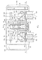
本実施形態では、撮影機能付観察光学装置は撮影機能付双眼鏡として構成される。先ず、図1を参照すると、本発明による撮影機能付双眼鏡の内部構造が示され、図2を参照すると、図1のII-II線に沿う断面図が示されている。本実施形態では、撮影機能付双眼鏡は略直方形を呈するケーシング10を具備し、このケーシング10はケーシング本体部分10Aと可動ケーシング部分10Bとから成る。
【0019】
ケーシング10内には一対の観察光学系12R及び12Lが設けられ、この一対の観察光学系12R及び12Lは左右対象な構成を有し、それぞれ右眼観察用及び左眼観察用として使用される。右側観察光学系12Rはケーシング本体部分10Aに組み込まれ、この右側観察光学系12Rには対物レンズ系14R、光学プリズム系16R及び接眼レンズ系18Rが含まれる。ケーシング本体部分10Aの前方壁には観察窓19Rが形成され、この観察窓19Rは右側観察光学系12Rの対物レンズ系14Rと整列させられる。また、左側観察光学系12Lは可動ケーシング部分10B側に組み込まれ、この左側観察光学系12Lには対物レンズ系14L、光学プリズム系16L及び接眼レンズ系18Lが含まれる。可動ケーシング部分10Bの前方壁には観察窓19Lが形成され、この観察窓19Lは左側観察光学系12Lの対物レンズ系14Lと整列させられる。
【0020】
なお、以下の記載では、説明の便宜上、前方側及び後方側とはそれぞれ撮影機能付双眼鏡の観察光学系(12R、12L)に対して対物側及び接眼側として定義される。
【0021】
可動ケーシング部分10Bはケーシング本体部分10Aから左方側に引き出し得るように該ケーシング本体部分10Aに対して摺動自在に係合させられる。即ち、可動ケーシング部分10Bは図2に示す収納位置と図3に示す最大引出し位置との間で左右方向に移動自在とされる。可動ケーシング部分10Bとケーシング本体部分10Aとの間の摺動係合面には或る程度の摩擦力が働くようになっており、このためケーシング本体部分10Aに対して可動ケーシング部分10Bを移動させる際には双方の部分10A及び10B間に所定以上の引出し力或いは押込み力を及ぼすことが必要となる。要するに、可動ケーシング部分10Bはその収納位置(図2)と最大引出し位置(図3)との間の任意の位置で摩擦力で留めておくことが可能である。
【0022】
図2及び図3の比較から明らかなように、可動ケーシング部分10Bがケーシング本体部分10Aから引き出されたとき、左側観察光学系12Lは可動ケーシング部分10Bと共に移動するが、しかし右側観察光学系12Rはケーシング本体部分10A側に留められる。即ち、可動ケーシング部分10Bをケーシング本体部分10Aに対して任意の引出し位置に位置決めすることにより、右側観察光学系12Rの接眼レンズ系18Rと左側観察光学系12Lの接眼レンズ系18Lとの光軸間距離即ち眼幅を調節することが可能である。
【0023】
本実施形態においては、右側観察光学系12Rの対物レンズ系14Rはケーシング本体部分10Aに対して固定位置に設置されるが、その光学プリズム系16R及び接眼レンズ系18Rは対物レンズ系14Rに対して前後方向に移動可能であり、これにより右側観察光学系12Rの合焦(フォーカシング)が行われる。同様に、左側観察光学系12Lの対物レンズ系14Lは可動ケーシング部分10Bに対して固定位置に設置されるが、その光学プリズム系16L及び接眼レンズ系18Lは対物レンズ系14Lに対して前後方向に移動可能であり、これにより左側観察光学系12Lの合焦(フォーカシング)が行われる。
【0024】
以上で述べたような眼幅調節及び合焦動作を行わせるために、ケーシング10の底部側には図4に示すような支持板構造体20が設けられる。なお、図1では、図示の複雑化を避けるために支持板構造体20は省かれている。
【0025】
支持板構造体20は、ケーシング本体部分10Aに対して適宜固定された矩形状固定板20Aと、この矩形状固定板20A上に摺動自在に配置されかつ可動ケーシング部分10Bに対して適宜固定されたスライド板20Bとから成る。スライド板20Bは矩形状固定板20Aの前後方向の幅にほぼ等しい幅を持つ矩形状部22と、この矩形状部22から右方側に一体的に延在した延在部24とから成る。右側観察光学系12Rの対物レンズ系14Rは矩形状固定板20A上の所定位置に固定設置され、左側観察光学系12Lの対物レンズ系14Lはスライド板20B上の所定位置に固定設置させられる。
【0026】
スライド板20Bの矩形状部22には一対の案内スロット26が形成され、またその延在部24には案内スロット27が形成される。一方、固定板22には、一対の案内スロット26に摺動自在に受け入れるようになった一対の案内ピン26′と、案内スロット27に摺動自在に受け入れるようになった案内ピン27′とが植設される。各案内スロット(26、27)は左右方向に同じ長さだけ延び、その長さはケーシング本体部分10Aに対する可動ケーシング部分10Bの移動距離、即ち可動ケーシング部分10Bの収納位置(図2)と可動ケーシング部分10Bの最大引出し位置(図3)との間の距離に対応する。
【0027】
図2及び図3から明らかなように、支持板構造体20はケーシング10内にその底部から適当な間隔を空けて設置され、このとき矩形状固定板20Aはケーシング本体部分10A側に適宜固定され、またスライド板20Bは可動ケーシング部分10B側に適宜固定される。なお、図示の実施形態では、可動ケーシング部分10Bに対するスライド板20Bの固定のために、その矩形状部22の左辺縁の一部に沿って取付片28が設けられ、この取付片28が可動ケーシング部分10Bの仕切り壁29に適宜固着される。
【0028】
図5を参照すると、右側観察光学系12Rの光学プリズム系16Rを搭載するための右側マウント板30Rと、左側観察光学系12Lの光学プリズム系16Lを搭載するための左側マウント板30Lが示される。図5及び図6から明らかなように、右側マウント板30R及び左側マウント板30Lのそれぞれの後方側縁辺に沿って直立板32R及び32Lが設けられる。図1に示すように、右側直立板32Rは右側接眼レンズ系18Rの取付座として用いられ、左側直立板32Lは左側接眼レンズ系18Lの取付座として用いられる。
【0029】
図6に示すように、右側マウント板30Rの底面にはその右側縁辺のほぼ中央に沿って案内シュー34Rが固着され、この案内シュー34Rには図2及び図3に示すように矩形状固定板20Aの右側端縁を摺動自在に受け入れる溝36Rが形成される。また、右側マウント板30Rの左側縁辺に沿って側壁38Rが設けられ、この側壁38Rの底部側は肥大部40Rとして形成され、この肥大部40Rには案内ロッド42Rを摺動自在に挿通させるボアが形成される。案内ロッド42Rの両端は矩形状固定板20Aの前方側縁辺及び後方側縁辺にそれぞれ一体的に形成された一対の対向直立支持片44Rに形成された孔に挿通させられて適宜固定される。
【0030】
一方、左側マウント板30Lの底面にはその左側縁辺のほぼ中央に沿って案内シュー34Lが固着され、この案内シュー34Lには図2及び図3に示すようにスライド板20Bの左側端縁を摺動自在に受け入れる溝36Lが形成される。また、左側マウント板30Lの右側縁辺に沿って側壁38Lが設けられ、この側壁38Lの底部側は肥大部40Lとして形成され、この肥大部40Lには案内ロッド42Lを摺動自在に挿通させるボアが形成される。案内ロッド42Lの両端はスライド板20Bの前方側縁辺及び後方側縁辺にそれぞれ一体的に形成された一対の対向直立支持片44Lに形成された孔に挿通させられて適宜固定される。
【0031】
なお、上述したように、支持板構造体20は図1では省かれているが、一対の対向直立支持片44Rと一対の対向直立支持片44Lとについては図示されている。
【0032】
右側観察光学系12Rの対物レンズ系14Rは右側マウント板30Rの前方側に配置されているので、右側マウント板30Rを案内ロッド42Rに沿って前後に移動させることにより、対物レンズ系14Rと光学プリズム系16Rとの距離が調節させられ、このため右側観察光学系12Rの合焦動作が行われることになる。同様に、左側観察光学系12Lの対物レンズ系14Lは左側マウント板30Lの前方側に配置されているので、左側マウント板30Lを案内ロッド42Lに沿って前後に移動させることにより、対物レンズ系14Lと光学プリズム系16Lとの距離が調節させられ、このため左側観察光学系12Lの合焦動作が行われることになる。
【0033】
右側マウント板30R及び左側マウント板30Lをそれぞれの案内ロッド42R及び42Lに沿って同期して移動させると共に右側マウント板30Rに対する左側マウント板30Lの左右方向の移動を許容させるために、図5に最もよく示すように、右側マウント板30R及び左側マウント板30Lは伸縮自在の連結手段46によって互いに連結させられる。
【0034】
詳述すると、本実施形態では、連結手段46は、右側マウント板30Rの側壁40Rの肥大部42Rの前方端部から左方側に延びた横断面矩形状のロッド部材46Aと、このロッド部材46Aを摺動自在に受け入れる二股部材46Bとから成る。ロッド部材46A及び二股部材46Bの長さについては、可動ケーシング部分10Bが収納位置(図2)から最大引出し位置(図3)まで引き出された際にもロッド部材46Aと二股部材46Bとの摺動係合が維持され得るものとされる。かくして、可動ケーシング部分10Bがケーシング本体部分10Aに対してどのような引出し位置にあっても、右側マウント板30R及び左側マウント板30Lはそれぞれの案内ロッド42R及び42Lに沿って同期して移動することができる。なお、ロッド部材46Aには横断面矩形状の孔47が形成されるが、この孔47の機能については後で説明する。
【0035】
図7を参照すると、図1のVII-VII線に沿って切断された縦断面図が示される。図1及び図7から明らかなように、ケーシング本体部分10Aの前方壁面には円形開口部48が形成され、この円形開口部48は可動ケーシング部分10Bがケーシング本体部分10Aに対して収納位置に置かれているときケーシング10の前方壁の中央に位置させられる。
【0036】
ケーシング本体部分10Aの前方側壁の内側壁面からは円形開口部48を取り囲むように前方スリーブ部材50が一体的に突出させられ、この前方スリーブ部材50の頂部側は図7に示すようにケーシング本体部分10Aと一体化させられる。一方、前方スリーブ部材50から後方側に所定の間隔を置いて後方スリーブ部材52が配置させられ、この後方スリーブ部材52はケーシング本体部分10Aの頂部壁の内側壁面から吊下するような態様で一体成形される。
【0037】
前方スリーブ部材50と後方スリーブ部材52とは互いに整列させられ、その間には転輪軸筒54が回転自在に適宜保持される。転輪軸筒54には転輪部56が後方スリーブ部材52に接近して設けられ、この転輪部56は転輪軸筒54の周囲拡張部として一体的に形成される。転輪部56が後方スリーブ部材52に接近して一体的に形成され、この転輪部56の一部はケーシング本体部分10Aの頂部壁に形成された矩形開口部58を通して外部に露出させられる。なお、一対の観察光学系12R及び12Lの合焦動作時、転輪部56の露出部分は本発明による撮影機能付双眼鏡の観察者の例えば人指し指によって回転させられるようになっている。
【0038】
転輪軸筒54にはその前方端と転輪部56との間に雄ねじ60が形成され、この雄ねじ60には環状体62が螺着される。図2、図4及び図7から明らかなように、環状体62には半径方向外側に突出する突起部64が形成され、この突起部64の先端は連結手段46のロッド部材46Aに形成された横断面矩形状の孔47に嵌入させられる。従って、転輪部56が回転させられると、環状体62は転輪軸筒54の雄ねじ60と螺着されているためにその長手軸線方向に沿って移動させられ、その移動方向は転輪部56の回転方向に依存する。要するに、転輪軸筒54と環状体62とは転輪軸筒54の回転運動を環状体62の直線運動に変換させる運動変換機構を形成する。
【0039】
環状体62の突起部64の先端は連結手段46のロッド部材46Aの孔47に嵌入されているので、環状体62の移動に伴い、右マウント板30R及び左マウント板30Lも移動させられる。要するに、転輪部56の回転により、対物レンズ系14R及び14Lのそれぞれに対する光学プリズム系16R及び16Lの距離が調整され、このため一対の観察光学系12R及び12Lの合焦動作が行われることになる。
【0040】
環状体62が両対物レンズ系に最も近い位置(以下、収納位置)にあるとき、両接眼レンズ系18R、18Lはケーシング10内に完全に収納された位置にあり、撮影機能付双眼鏡は最もコンパクトな状態となる。そして、使用時においては、転輪部56を操作して、この収納位置から若干対物光学系から離れた位置にある観察位置まで移動させるように構成されている。即ち、非使用時においては、ユーザが転輪部を回転操作して接眼レンズ系18R,18Lをケーシング内に収納し、最もコンパクトな状態で携行できるように構成されている。
【0041】
本実施形態では、一対の観察光学系12R及び12Lについては、例えば、環状体62が上記観察位置にあるときに40メール先から無限遠までの観察対象物の合焦が得られるようなパンフォーカス設計とされ、2メートル先から40メートル先までの観察対象物を観察するとき、転輪軸筒54の回転により光学プリズム系16R及び16Lをそれぞれ対物レンズ系14R及び14Lから引き離して観察対象物の合焦が行われる。勿論、光学プリズム系16R及び16Lがそれぞれ対物レンズ系14R及び14Lから最大距離まで引き離されたとき、2メートル先の観察対象物の合焦が得られることになる。
【0042】
転輪軸筒54内にはレンズ鏡筒66が設置させられ、このレンズ鏡筒66内には第1レンズ群68と第2レンズ群70とから成る撮影光学系が保持される。一方、ケーシング本体部分10Aの後方側壁の内側壁面には回路基板72が取り付けられ、この回路基板72上には固体撮像素子例えばCCD(charge-coupled device)撮像素子74が搭載され、このCCD撮像素子74はその受光面が撮影光学系(68、70)と整列するように配置される。後方スリーブ部材52の後方端面側には内側フランジ部が形成され、その内側フランジ部には光学的ローパスフィルタ76が支持される。要するに、本実施形態では、撮影機能付双眼鏡には所謂デジタルカメラとしての撮影機能が与えられ、被写体は撮影光学系(68、70)によって光学的ローパスフィルタ76を通してCCD撮像素子74の受光面に結像させられる。
【0043】
図1ないし図3では、撮影光学系(68、70)の光軸は参照符号OSで示され、また右側及び左側観察光学系12R及び12Lのそれぞれの光軸が参照符号OR及びOLで示される。勿論、右側及び左側観察光学系12R及び12Lの光軸OR及びOLは互いに平行であり、しかも撮影光学系(68、70)の光軸OSとも平行である。図2及び図3に示すように、右側及び左側観察光学系12R及び12Lの光軸OR及びOLは撮影光学系(68、70)の光軸OSに平行な平面Pを決定し、右側及び左側観察光学系12R及び12Lは該平面Pに対して平行に移動することによりその光軸間距離即ち眼幅の調節がなされる。
【0044】
もし撮影光学系(68、70)が適当な距離の前景被写体から無限遠の遠景被写体までの合焦が得られるようなパンフォーカス設計とされ、しかもその合焦可能範囲内だけで撮影を行うことが前提とされている場合には、レンズ鏡筒66に合焦機構を組み込むことは必要とされない。しかしながら、本発明による撮影機能付双眼鏡を通常のカメラの場合と同様に、例えば2メール先の前景被写体についても撮影することが望まれる場合には、レンズ鏡筒66にも合焦機構が必要となる。
【0045】
そこで、本実施形態では、転輪軸筒54の内周壁面には雌ねじが形成され、一方レンズ鏡筒66の外周壁面には雄ねじが形成され、これによりレンズ鏡筒66は転輪軸筒54内で螺着される。レンズ鏡筒66の前方端部は前方スリーブ部材50内に挿入させられ、該前方端部には図7に示すように一対のキー溝78が直径方向に形成され、各キー溝78はレンズ鏡筒66の前方端縁からその長手軸線方向に沿って所定長さだけ延びる。一方、前方スリーブ部材50の後方側端面に接近した箇所には一対のボアが直径方向に形成され、各ボアにはキー溝78に係合するようになったピン要素80が植設される。要するに、キー溝78とピン要素80との係合により、レンズ鏡筒66の回転が阻止される。
【0046】
かくして、転輪軸筒54がその転輪部56の操作により回転させられると、レンズ鏡筒66はその光軸に沿って移動させられる。即ち、転輪軸筒54の内周壁面に形成された雌ねじとレンズ鏡筒66の外周壁面に形成された雄ねじとは該転輪軸筒54の回転運動をレンズ鏡筒66の直線運動に変換するための運動変換機能を形成し、この運動変換機構はレンズ鏡筒66の合焦機構として機能させられる。
【0047】
転輪軸筒54の外周壁面に形成される雄ねじ60とその内周壁面に形成される雌ねじとは互いに逆向きとされ、このため転輪軸筒54が光学プリズム系16R及び16Lをそれぞれ対物レンズ系14R及び14Lから引き離すように回転させられたとき、レンズ鏡筒66はCCD撮像素子74から遠のくように移動させられ、かくしてパンフォーカスの範囲から外れた前景被写体がCCD撮像素子74の受光面に合焦された状態で結像される。勿論、転輪軸筒54の外周壁面の雄ねじピッチ及びその内周壁面の雌ねじピッチのそれぞれについては、一対の観察光学系12R及び12Lの光学特性及び撮影光学系(68、70)の光学特性に応じて異なったものとされる。
【0048】
図2、図3及び図7に示すように、ケーシング本体部分10Aの底部壁の下側壁面には三脚の雲台の雄ねじと螺着するようになった雌ねじ孔81が形成される。図2から明らかなように、可動ケーシング部分10Bがケーシング本体部分10Aに対して収納位置にあるとき、雌ねじ孔81はケーシング10の左右長のほぼ中央に位置し、その位置は撮影光学系(68、70)の光軸の直下となる。また、図7から明らかなように、雌ねじ孔81はケーシング本体部分10Aの前方側縁辺に近接して配置される。
【0049】
図1、図2及び図3に示すように、ケーシング本体部分10Aの右側端部内には電源回路基板82が設けられ、この電源回路基板82はケーシング本体部分10Aに対して適宜保持される。また、図2及び図3に示すように、ケーシング本体部分10Aの底部壁と支持板構造体20との間には主制御回路基板84が設けられ、この主制御回路基板84はケーシング本体部分10Aの底部壁によって適宜支持される。主制御回路基板84にはマイクロコンピュータやメモリ等の電子部品が搭載され、CCD搭載用回路基板72及び電源回路基板82は平坦なフレキシブル配線コード(図示されない)を介して主制御回路基板84に適宜接続される。
【0050】
本実施形態では、図2、図3及び図7に示すように、ケーシング本体部分10Aの頂部壁の外側壁面にはLCD(liquid crystal display)表示器86が配置され、このLCD表示86は平坦な矩形状を呈する。矩形状LCD表示器86はその一方の対向側辺が撮影光学系(68、70)の光軸に対して直角となるように配置され、しかもその前方側縁辺に沿う回動軸88のまわりで回動自在とされる。矩形状LCD表示器86は通常は図7に実線で示す収納位置に置かれ、このとき矩形状LCD表示器86の液晶表示画面はケーシング本体部分10Aの頂部壁の上側壁面に対して直接対向しかつ平行となるような姿勢とされるので、その液晶表示画面はモニタされ得ない。CCD撮像素子74によって撮影作動が行われるとき、LCD表示器86はその収納位置から図7で破線で部分的に示すような表示位置まで手動操作により回動させられ、このときLCD表示器86の液晶表示画面が接眼レンズ系18R及び18Lの側からモニタされ得るようになっている。
【0051】
図1、図2及び図3から明らかなように、可動ケーシング部分10Bの左側端部内は仕切り壁29によって仕切られ、その内部はバッテリ充填室90として郭成される。バッテリ充填室90には二本のバッテリ92が充填され、電源回路基板82は給電配線コード(図示されない)を介してバッテリ92から給電を受け、CCD搭載用回路基板72上のCCD撮像素子、主制御回路基板84上のマイクロコンピュータやメモリ等の電子部品及びLCD表示器86は電源回路基板82から給電される。
【0052】
図2及び図3に最もよく示すように、電源回路基板82には2つの接続コネクタ、即ちビデオ出力端子コネクタ出力94とUSB出力端子コネクタ95とが上下方向に並んで搭載され、これら接続コネクタ94及び95は例えば画像処理コンピュータ(図示されない)との接続ために用いられる。電源回路基板82は接続コネクタ94及び95と共にシールドカバー96によって覆われ、シールドカバー96については適当な導体材料例えば適当な厚さの鋼板から形成することができる。
【0053】
また、図2及び図3に示すように、主制御回路基板84の下側にはCFカードホルダ97が設けられ、このCFカードホルダ97にはCFカードがメモリカードとして抜差し自在に挿入し得るようになっている。
【0054】
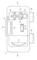
図8及び図9を参照すると、本発明による撮影機能付双眼鏡の外観が平面図として図示される。図8及び図9において、参照符号18R′及び18L′はそれぞれ接眼レンズ系18R及び18Lを収納するためのレンズ鏡筒を示し、これらレンズ鏡筒18R′及び18L′の各々は横断面矩形状となっている。レンズ鏡筒18R′は右側マウント板30Rの後方縁辺に沿う直立板32Rに装着され、レンズ鏡筒18L′は左側マウント板30Lの後方側縁辺に沿う直立板32Lに装着される(図6)。なお、参照符号98は可動ケーシング部分10Bの頂部壁の上側壁面に形成された略半月状凹部を示し、この略半月状凹部98には可動ケーシング部分10Bをケーシング本体部分10Aから引き出す際に指を引っかけることができるので、ケーシング本体部分10Aからの可動ケーシング部分10Bの引出しを容易に行うことができる。
【0055】
図8ではLCD表示器86は収納位置で示され、また図9ではLCD表示器86は表示位置で示され、その液晶表示画面は参照符号100で示される。図8及び図9から明らかなように、LCD表示器86が収納位置から表示位置まで移動させられると、LCD表示器86の液晶表示画面100は撮影機能付双眼鏡の後方側即ち接眼側に向けられるので、観察者は観察動作時に撮影機能付双眼鏡を少し下げることによりLCD表示器86の液晶表示画面100をモニタすることができるだけでなく撮影機能付双眼鏡を少し上げることにより直ちに観察動作に戻ることもできる。要するに、観察者は一対の観察光学系12R及び12Lによる観察と液晶表示画面100のモニタとの切替を迅速に行うことができるので、観察対象物(被写体)を見失うことなく最良のシャッタチャンスを容易に捉えることが可能となる。
【0056】
また、図8から明らかなように、LCD表示器86が収納位置に置かれたとき、転輪部56の露出部はLCD表示器86によって完全覆われるので、撮影機能付双眼鏡の持ち運び時等に転輪部56が何かに触れて不用意に回転させられるというようなことが防止される。上述したように、撮影機能付双眼鏡の非使用時では、両接眼レンズ系18R、18Lはケーシング10内に完全に収納され、このとき撮影機能付双眼鏡は最もコンパクトな状態とされる。従って、このような状態でLCD表示器86で転輪部56の露出部が覆われると、転輪部56が不用意に操作あるいは動かされることが防止されるので、撮影機能付双眼鏡の最もコンパクトな収納状態が維持され得る。
【0057】
図8及び図9に示すように、ケーシング本体部分10Aの頂部壁の上側壁面上にはレリーズスイッチ102、被写体像表示スイッチ104、メニュー表示スイッチ106及び方向スイッチ108が設けられ、これらスイッチは右側観察光学系12Rの上方領域に纏めて配置される。これらのスイッチは、不図示の電源スイッチと同様に、主制御回路基板84上の不図示のマイクロコンピュータに接続されており、マイクロコンピュータはこれらスイッチの入力状態に基づいて、各スイッチ操作に割り当てられた動作を行う。勿論、スイッチ102、104、106及び108の操作は電源スイッチのオフ状態では無効であり、電源スイッチのオン後に有効となる。なお、電源スイッチはケーシング本体部分10Aの側壁の適当な箇所に設けられ、その頂部壁の上側壁面上には配置されない。
【0058】
レリーズスイッチ102は撮影動作を開始させるスイッチであり、レリーズスイッチ102の押下により撮影作動が開始される。
【0059】
被写体像表示スイッチ104はLCD表示器86の液晶表示画面100に被写体像を動画として表示させるか否かを選択する切替スイッチである。電源スイッチのオン直後では、LCD表示器86の液晶表示画面100は何も表示されていない無表示状態とされる。被写体像表示スイッチ104が押下されると、即ち被写体像表示スイッチ104のオン操作が行われると、LCD表示器86の液晶表示画面100に被写体像が動画として表示される。被写体像表示スイッチ104が再び押下されると、即ち被写体像表示スイッチ104のオフ操作が行われると、液晶表示画面100は無表示状態に戻る。要するに、撮影機能付双眼鏡の電源スイッチがオン状態で被写体像表示スイッチ104が押下される度毎に、そのオン操作及びオフ操作が繰り返され、オン操作時にLCD表示器86での動画表示が行われ、オフ操作時にLCD表示器86での動画表示が解除されて無表示状態となる。
【0060】
メニュー表示スイッチ106はLCD表示器86の液晶表示画面100にメニュー選択画面を表示させるか否かを選択する切替スイッチである。電源スイッチのオン直後では、LCD表示器86の液晶表示画面100は何も表示されていない無表示状態とされる。メニュー表示スイッチ106が押下されると、LCD表示器86の液晶表示画面100には種々の設定項目を含むメニュー選択画面が表示される。このとき方向スイッチ108のいずれかを押下することにより、設定項目が反転表示により選択されて確定される。メニュー表示スイッチ106が再び押下されると、液晶表示画面100は無表示状態に戻る。
【0061】
電源スイッチのオン後に被写体像表示スイッチ104が押下されると、CCD撮像素子74の受光面に結像された被写体像は一フレーム分の画像データに光電変換され、その一フレーム分の画像信号は所定の時間間隔で順次読み出されて適宜画像処理された後に一フレーム分のデジタル画像データに変換される。次いで、一フレーム分の画像データは主制御回路基板84上のフレームメモリに一旦書き込まれ、そのフレームメモリからデジタルビデオ信号として読み出される。続いて、デジタルビデオ信号はアナログビデオ信号に変換された後に適宜画像処理されてLCD表示器86に送られ、これによりLCD表示器86の液晶表示画面100には被写体像が動画として再現表示される。勿論、被写体像表示スイッチ104が再び押下されると、LCD表示器86の液晶表示画面100は無表示状態に戻る。
【0062】
レリーズスイッチ102がオンされると、上述のフレームメモリに書き込まれた一フレーム分の画像データが静止画像データとして読み出されて、主制御回路基板84上のマイクロコンピュータ内のメモリに取り込まれ、そこで適宜画像処理された後にCFカード97に所定のフォーマットに従って書き込まれる。CFカード97は必要に応じてCFカードホルダ97から取り出され、例えば画像処理コンピュータのCFカード用ドライバに装填され、そこで一フレーム分の画像データは適宜処理された後に例えばプリンタによって撮影画像として出力される。一方、撮影機能付双眼鏡が接続コネクタ94或いは95を介して画像処理コンピュータに接続されている場合には、CFカードをCFカードホルダ97に装填された儘でその画像データを画像処理コンピュータに転送することも可能である。
【0063】
図10は図7と同様な縦断面図であって、上述した実施形態の変形実施形態を示す図である。図10に示す変形実施形態では、転輪軸筒54の回転運動を環状体62の直線運動に変換するための運動変換機構と転輪軸筒54の回転運動をレンズ鏡筒66の直線運動に変換するための運動変換機構とが上述した実施形態の場合とは異なり、この点を除けば図10の撮影機能付双眼鏡は図1ないし図9に示した撮影機能付双眼鏡と実質的に同じものである。なお、図10では、図7に示した構成要素と同様な構成要素については同じ参照符号が用いられる。
【0064】
詳述すると、図10に示す変形実施形態では、転輪軸筒54の外周壁面にはカム溝110(図10では、カム溝110が平面上に展開された状態で破線によって示される)が形成され、このカム溝110には環状体62の内側壁面からカムフォロワとして突出した短軸112が摺動係合させられ、このカム溝110と短軸112とにより、転輪軸筒54の回転運動を環状体62の直線運動に変換するための運動変換機構が形成される。一方、転輪軸筒54の内周壁面にはカム溝114(図10では、カム溝114が平面上に展開された状態で破線によって示される)が形成され、このカム溝114にはレンズ鏡筒66の外側壁面からカムフォロワとして突出した短軸116が摺動係合させられ、このカム溝114と短軸116とにより、転輪軸筒54の回転運動をレンズ鏡筒66の直線運動に変換するための運動変換機構が形成される。
【0065】
図1ないし図9に示す実施形態のように、運動変換機構が雄ねじと雌ねじとの螺着により形成される場合、転輪軸筒54の回転量は環状体62或いはレンズ鏡筒66の直線運動量に対して線型関係となる。しかしながら、一対の観察光学系12R及び12L或いは撮影光学系(68、70)の合焦位置については、対物光学系14R及び14Lに対する光学プリズム系16R及び16Lとの距離或いはCCD撮像素子74の受光面に対する撮影光学系(68、70)に対する距離に対して必ずしも線型関係とはならない。
【0066】
従って、一対の観察光学系12R及び12L或いは撮影光学系(68、70)について正確な合焦位置を得るためには、図10に示すような変形実施形態の場合のように、運動変換機構についてはカム溝(110、114)と短軸(112、116)とにより形成することが好ましい。というのは、勿論、転輪軸筒54の回転量と環状体62或いはレンズ鏡筒66の直線運動量との関係を容易に非線型とすることが可能であり、その結果として、一対の観察光学系12R及び12L或いは撮影光学系(68、70)について正確な合焦位置が得られるからである。しかしながら、実際には、一対の観察光学系12R及び12Lについても或いは撮影光学系(68、70)についても或る程度の焦点深度が得られるので、図1ないし図9に示す実施形態のように、運動変換機構を雄ねじと雌ねじとの螺着により形成しても特に差し支えはない。
【0067】
図11及び図12を参照すると、本発明による撮影機能付双眼鏡の別の実施形態が示され、この実施形態はLCD表示器86の右方側辺から張出し部118が突出させられている点を除けば上述した実施形態と同じものである。なお、図11及び図12は図8及び図9にそれぞれ対応するものであり、図11及び図12では、図8及び図9に示す構成要素と同様な構成要素については同じ参照符号が用いられている。
【0068】
図11及び図12の比較から明らかなように、張出し部118はLCD表示器86が表示位置(図12)から収納位置(図11)に戻されたとき、張出し部118は被写体像表示スイッチ104を覆うように機能する。換言すれば、LCD表示器86が収納位置に置かれたとき、被写体像表示スイッチ104は張出し部118によって覆い隠されるようにLCD表示器86の右方側辺に隣接して配置される。このような構成によれば、撮影機能付双眼鏡の電源スイッチがオン状態でしかもLCD表示器86に被写体像を動画として表示する必要のないとき(即ち、LCD表示器86が収納位置に置かれているとき)、被写体像表示スイッチ104を誤って操作することが回避され得る。
【0069】
例えば、LCD表示器86を収納位置に置いた状態で撮影機能付双眼鏡を持ち運ぶとき、被写体像表示スイッチ104は張出し部118によって覆い隠されているので、被写体像表示スイッチ104が誤って動作されてLCD表示器86での動画表示が無用に行われるということは回避され、このため撮影機能付観察光学装置のバッテリ92が無駄に消費されるとうい事態が回避される。
【0070】
なお、LCD表示器86が収納位置に置かれたとき、被写体像表示スイッチ104が転輪部56のようにLCD表示器86自体によって覆い隠されるような位置に配置されている場合には、勿論、LCD表示器86に張出し部118を設ける必要は無い。
【0071】
【発明の効果】
以上の記載から明らかなように、本発明による撮影機能付双眼鏡にあっては、観察者は被写体像をモニタするための表示器の表示画面と一対の観察光学系12R及び12Lによる観察との切替を迅速に行うことができるので、観察対象物(被写体)を見失うことなく最良のシャッタチャンスを容易に捉えることが可能となる。
【0072】
また、本発明による撮影機能付双眼鏡においては、転輪軸筒内に撮影光学系が組み込まれるので、その双眼鏡としての機能を果たすために必要とされる全体構成以上に大巾に嵩張らせることなく撮影機能を組み込むことが可能であり、また撮影光学系は一対の観察光学系とは独立しているので、十分な光量で撮影を行うことができる。なお、双眼鏡の転輪部には観察者の指で容易に回転し得るように比較的大きな径が与えられるので、該転輪部の回転軸が撮影光学系を設置するための転輪軸筒として形成されたとしても、双眼鏡としての機能を果たすために必要とされる全体構成が大巾に嵩張るというようなことはない。
【図面の簡単な説明】
【図1】本発明による撮影機能付双眼鏡の一実施形態を示す平面断面図である。
【図2】図1のII-II線に沿う断面図であって、撮影機能付双眼鏡の可動ケーシング部分を収納位置で示す図である。
【図3】図2の同様な断面図であって、撮影機能付双眼鏡の可動ケーシング部分を最大引出し位置で示す図である。
【図4】撮影機能付双眼鏡のケーシング内に設けられる支持板構造体の平面図である。
【図5】図4に示す支持板構造体上に設置される右側マウント板及び左側マウント板の平面図である。
【図6】図5のVI-VI線に沿う矢視図である。
【図7】図1のVII-VII線に沿う縦断面図である。
【図8】本発明による撮影機能付双眼鏡の外観を示す平面図であって、LCD表示器を収納位置で示す図である。
【図9】図8と同様な平面図であって、LCD表示器を表示位置で示す図である。
【図10】図7と同様な縦断面図であって、本発明による撮影機能付双眼鏡の変形実施形態を示す図である。
【図11】本発明による撮影機能付双眼鏡の別の実施形態の外観を示す、図8に対応した平面図であって、LCD表示器を収納位置で示す図である。
【図12】図11と同様な平面図であって、LCD表示器を表示位置で示す図である。
【符号の説明】
10 ケーシング
10A ケーシング本体部分
10B 可動ケーシング部分
12R 右側観察光学系
12L 左側観察光学系
20 支持板構造体
20A 矩形状固定板
20B スライド板
30R 右側マウント板
30L 左側マウント板
46 連結手段
46A ロッド部材
46B 二股部材
50 前方スリーブ部材
52 後方スリーブ部材
54 転輪軸筒
56 転輪部
62 環状体
66 レンズ鏡筒
68 第1レンズ群
70 第2レンズ群
74 CCD撮像素子
76 光学的ローパスフィルタ
86 LCD表示器
100 液晶表示画面[0001]
BACKGROUND OF THE INVENTION
The present invention relates to an observation optical apparatus with a photographing function equipped with a photographing system.
[0002]
[Prior art]
As is well known, observation optical devices such as binoculars and monoculars are used for sports watching and bird watching, for example. In such a case, spectators and observers often encounter scenes that they want to record as photographs, but it is easy to imagine missing a photo opportunity while switching the observation optical device to the camera. Therefore, it has already been proposed that the observation optical device is equipped with a photographing function so that photographing can be performed immediately without missing a shutter chance while watching or observing with the observation optical device. For example, Japanese Utility Model Laid-Open No. 6-2330 discloses a binocular with a photographing function of a type in which a camera unit is mounted on the top of the binoculars.
[0003]
By the way, when a so-called digital camera function is given as an imaging function to an observation optical apparatus with an imaging function, for example, a monitor display such as an LCD (liquid crystal display) is used to monitor a subject image as in a normal digital camera. Although it is desirable to install a display device on an observation optical device with a photographing function, the installation location of such an LCD display is determined in consideration of the function of the observation optical device with a photographing function as a binocular or a monocular. Should be done. In other words, the main function of the observation optical device with a photographing function is a function as a binocular or a monocular, and thus the observation of the LCD display can be performed without much hindrance to the observer's observation operation when observing with the binocular or the monocular. It is necessary to consider the location of the LCD display so that the display screen can be easily monitored.
[0004]
In addition, when an LCD display is installed in the observation optical device with a photographing function, a subject image display switch for selecting whether or not to display a subject image on the LCD display is provided as appropriate for the casing of the observation optical device with a photographing function. It is necessary to provide it at a place. As with conventional digital cameras, when the subject image display switch is turned on with the power switch turned on, the subject image captured by the photographing optical system is displayed as a moving image on the LCD display, and the moving image is displayed as the subject image. It is solved by turning off the display switch. In the case of an observation optical device with a photographing function, unlike a digital camera, it is often used only for observation purposes, so it is often carried for a long time with the camera removed from the case. Often. Therefore, for example, when the subject image display switch is inadvertently turned on when the power switch of the observation optical device with a photographing function is carried in the ON state, the moving image display on the LCD display is performed unnecessarily. When the battery power of the observation optical device with a photographing function is consumed wastefully, it is said that the observation optical device with the photographing function is wasted.
[0005]
Further, as disclosed in the above-mentioned Japanese Utility Model Laid-Open No. 6-2330, in the case of an observation optical device with an imaging function in which a camera unit is simply added to binoculars as an observation optical device, the entire configuration is It must be said that the structure is bulky as much as the camera part, and that it is difficult to put into practical use in terms of usability.
[0006]
On the other hand, an observation optical apparatus with a photographing function of a type in which a half mirror is incorporated in one of the observation optical systems to guide an observation image obtained from the observation optical system to the photographing optical system has been proposed. In such an observation optical apparatus with a photographing function, a part of the photographing optical system is substituted by an objective lens system of the observation optical system. Therefore, this type of observation optical device with a photographing function can be configured more compactly than that disclosed in the above-mentioned Japanese Utility Model Laid-Open No. 6-2330, but the amount of light guided to the photographing optical system of the camera is small. This is a problem. That is, only about half of the total amount of light introduced into the observation optical system is guided to the photographing optical system.
[0007]
[Problems to be solved by the invention]
Accordingly, an object of the present invention is to provide an observation optical apparatus with an imaging function equipped with an imaging optical system, and an observation optical apparatus with an imaging function that is devised with respect to the installation location of the monitor for monitoring the subject image. .
[0008]
Another object of the present invention is an observation optical apparatus with a photographing function as described above, which does not require operation of a subject image display switch for selecting whether or not to display a subject image on a monitor display. It is to provide an observation optical device with a photographing function configured to reliably avoid the erroneous operation.
[0009]
Still another object of the present invention is an observation optical apparatus with a photographing function as described above, which is not bulky more than the entire configuration required to fulfill its function as a binocular or a monocular. It is an object of the present invention to provide an observation optical apparatus with a photographing function.
[0010]
Still another object of the present invention is to provide an observation optical apparatus with a photographing function as described above, which can perform photographing with a sufficient amount of light.
[0011]
[Means for Solving the Problems]
An observation optical apparatus with a photographing function according to the present invention includes an observation optical system, a photographing optical system, the observation optical system, and the photographing optical system. Shadow A casing for housing the optical system, and a part of the observation optical system is movable relative to the other parts in order to focus the observation optical system. The observation optical device with a photographing function according to the present invention further converts a rotating part for focusing the observation optical system, and the rotational movement of the rolling part into relative movement of both parts of the observation optical system. A motion conversion mechanism for rotating the wheel portion partially exposed from the top wall of the casing for its rotational operation. ing . According to the present invention, in such an observation optical device with a photographing function, a monitor display for displaying a subject image captured by the photographing optical system is provided on the upper wall surface of the top wall of the casing. The display for display is rotatable between a storage position and a display position around a rotation axis perpendicular to the optical axis of the photographing optical system on the front edge side, and the monitor display is placed in the storage position. When the display screen of the monitor display is directed to the upper wall surface side of the top wall of the casing and the monitor display is placed at the display position, the display screen of the monitor display is When the monitor display is directed to the eyepiece side and placed in the storage position, the exposed portion of the wheel is covered by the monitor display.
[0012]
In a preferred embodiment of the present invention, a subject image display switch for selecting whether or not to display a subject image captured by the photographing optical system as a moving image on the monitor display is provided on the upper wall surface of the casing. When the monitor display is placed in the storage position, the subject image display switch is covered by the monitor display. Preferably, when the monitor display is placed in the storage position, a subject image display switch is disposed adjacent to the monitor display, and the monitor display has an overhanging portion for covering the subject image display switch. It is formed.
[0013]
Further, in a preferred embodiment of the present invention, the wheel part is configured as a peripheral extension part of the wheel shaft cylinder, and the photographing optical system is installed in the wheel shaft cylinder.
[0014]
Furthermore, in a preferred embodiment of the present invention, a pair of observation optical systems are provided, whereby the observation optical device with a photographing function is configured as binoculars. In this case, preferably, the casing includes a casing main body portion and a movable casing portion that is slidable with respect to the casing main body portion. One of the pair of observation optical systems is accommodated in the casing body portion, and the other of the pair of observation optical systems is accommodated in the movable casing portion, and the pair is obtained by moving the movable casing portion relative to the casing body portion. The eye width of the observation optical system is adjusted, and the monitor display is disposed on the top wall of the casing body.
[0015]
In still another preferred embodiment of the present invention, a focusing mechanism is provided for converting the rotational motion of the wheel barrel into the linear motion of the imaging optical system in order to focus the imaging optical system. In this case, preferably, a solid-state imaging device that is separated from the rear side end of the wheel barrel by a predetermined distance and aligned with the imaging optical system is provided, and a focal point of the imaging optical system is a light-receiving surface of the solid-state imaging device. The subject image captured by the solid-state image sensor is displayed on the monitor display as necessary.
[0016]
In still another preferred embodiment of the present invention, a part of the observation optical system is movable between a storage position completely accommodated in the casing and an observation position protruding from the casing. When a part is stored in the storage position, the observation optical device with a photographing function is in the most compact state.
[0017]
DETAILED DESCRIPTION OF THE INVENTION
Next, an embodiment of an observation optical apparatus with a photographing function according to the present invention will be described with reference to the accompanying drawings.
[0018]
In this embodiment, the observation optical device with a photographing function is configured as a binocular with a photographing function. First, referring to FIG. 1, there is shown the internal structure of the binoculars with photographing function according to the present invention, and FIG. 2 is a sectional view taken along line II-II in FIG. In the present embodiment, the binoculars with a photographing function includes a
[0019]
A pair of observation
[0020]
In the following description, for convenience of explanation, the front side and the rear side are defined as the objective side and the eyepiece side with respect to the observation optical system (12R, 12L) of the binoculars with photographing function, respectively.
[0021]
The
[0022]
As apparent from the comparison between FIGS. 2 and 3, when the
[0023]
In the present embodiment, the objective lens system 14R of the right observation
[0024]
In order to perform the eye width adjustment and the focusing operation as described above, a
[0025]
The
[0026]
A pair of
[0027]
As is apparent from FIGS. 2 and 3, the
[0028]
Referring to FIG. 5, a
[0029]
As shown in FIG. 6, a
[0030]
On the other hand, a
[0031]
As described above, the
[0032]
Since the objective lens system 14R of the right observation
[0033]
In order to allow the
[0034]
More specifically, in this embodiment, the connecting
[0035]
Referring to FIG. 7, a longitudinal sectional view taken along line VII-VII in FIG. 1 is shown. As apparent from FIGS. 1 and 7, a
[0036]
A
[0037]
The
[0038]
A
[0039]
Since the tip of the
[0040]
When the
[0041]
In the present embodiment, for the pair of observation
[0042]
A
[0043]
In FIG. 1 to FIG. 3, the optical axis of the photographing optical system (68, 70) is indicated by the reference symbol OS, and the optical axes of the right and left observation
[0044]
If the photographic optical system (68, 70) has a pan-focus design so as to obtain a focus from a foreground subject at an appropriate distance to a far-field subject at infinity, and photographing only within the focusable range. If it is assumed that the focusing mechanism is not incorporated into the
[0045]
Therefore, in the present embodiment, a female screw is formed on the inner peripheral wall surface of the
[0046]
Thus, when the
[0047]
The
[0048]
As shown in FIGS. 2, 3, and 7, a
[0049]
As shown in FIGS. 1, 2, and 3, a
[0050]
In this embodiment, as shown in FIGS. 2, 3 and 7, an LCD (liquid crystal display)
[0051]
As apparent from FIGS. 1, 2, and 3, the left end portion of the
[0052]
As best shown in FIGS. 2 and 3, two connection connectors, that is, a video output
[0053]
2 and 3, a
[0054]
8 and 9, the external appearance of the binoculars with photographing function according to the present invention is illustrated as a plan view. 8 and 9,
[0055]
In FIG. 8, the
[0056]
Further, as apparent from FIG. 8, when the
[0057]
As shown in FIGS. 8 and 9, a
[0058]
The
[0059]
The subject
[0060]
The
[0061]
When the subject
[0062]
When the
[0063]
FIG. 10 is a longitudinal sectional view similar to FIG. 7 and shows a modified embodiment of the above-described embodiment. In the modified embodiment shown in FIG. 10, the motion conversion mechanism for converting the rotational motion of the
[0064]
More specifically, in the modified embodiment shown in FIG. 10, a cam groove 110 (in FIG. 10, indicated by a broken line in a state where the
[0065]
When the motion conversion mechanism is formed by screwing a male screw and a female screw as in the embodiment shown in FIGS. 1 to 9, the rotation amount of the
[0066]
Therefore, in order to obtain an accurate in-focus position for the pair of observation
[0067]
Referring to FIGS. 11 and 12, another embodiment of the binoculars with photographing function according to the present invention is shown. In this embodiment, an overhanging
[0068]
As apparent from the comparison between FIG. 11 and FIG. 12, when the
[0069]
For example, when carrying the binoculars with a photographing function while the
[0070]
In addition, when the
[0071]
【The invention's effect】
As is clear from the above description, in the binoculars with a photographing function according to the present invention, the observer switches between the display screen of the display for monitoring the subject image and the observation by the pair of observation
[0072]
Further, in the binoculars with a photographing function according to the present invention, since a photographing optical system is incorporated in the wheel barrel, the photographing can be performed without making the entire structure larger than necessary for fulfilling the function as the binoculars. Functions can be incorporated, and the photographing optical system is independent of the pair of observation optical systems, so that photographing can be performed with a sufficient amount of light. The binoculars have a relatively large diameter so that they can be easily rotated by an observer's finger. Therefore, the rotation axis of the binoculars serves as a wheel cylinder for installing the photographing optical system. Even if it is formed, the overall configuration required to fulfill the function as binoculars is not greatly bulky.
[Brief description of the drawings]
FIG. 1 is a plan sectional view showing an embodiment of binoculars with a photographing function according to the present invention.
2 is a cross-sectional view taken along the line II-II in FIG. 1, showing a movable casing portion of binoculars with a photographing function in a storage position.
FIG. 3 is a cross-sectional view similar to FIG. 2, but showing the movable casing portion of the binoculars with photographing function in the maximum drawer position.
FIG. 4 is a plan view of a support plate structure provided in a casing of binoculars with a photographing function.
FIG. 5 is a plan view of a right mount plate and a left mount plate installed on the support plate structure shown in FIG.
6 is a view taken along the line VI-VI in FIG. 5;
7 is a longitudinal sectional view taken along line VII-VII in FIG.
FIG. 8 is a plan view showing the appearance of the binoculars with photographing function according to the present invention, and shows the LCD display in the storage position.
FIG. 9 is a plan view similar to FIG. 8, showing the LCD display at the display position.
FIG. 10 is a longitudinal sectional view similar to FIG. 7, showing a modified embodiment of the binoculars with photographing function according to the present invention.
FIG. 11 is a plan view corresponding to FIG. 8 showing the appearance of another embodiment of the binoculars with photographing function according to the present invention, and showing the LCD display in the storage position.
12 is a plan view similar to FIG. 11, showing the LCD display at the display position. FIG.
[Explanation of symbols]
10 Casing
10A casing body part
10B Movable casing part
12R Right side observation optical system
12L Left side observation optical system
20 Support plate structure
20A rectangular fixed plate
20B slide plate
30R Right side mounting plate
30L Left side mounting plate
46 Connection means
46A Rod member
46B Bifurcated member
50 Front sleeve member
52 Rear sleeve member
54 Roller shaft
56 Rolling part
62 Toroidal
66 Lens barrel
68 First lens group
70 Second lens group
74 CCD image sensor
76 Optical low-pass filter
86 LCD display
100 LCD display screen
Claims (8)
前記ケーシングの頂部壁の上側壁面には前記撮影光学系によって捉えられた被写体像を表示するためのモニタ用表示器が設けられ、このモニタ用表示器はその前方縁側で前記撮影光学系の光軸に対して直角な回動軸線のまわりで収納位置と表示位置との間で回動自在とされ、前記モニタ用表示器が前記収納位置に置かれたとき、該モニタ用表示器の表示画面が前記ケーシングの頂部壁の上側壁面側に向けられ、前記モニタ用表示器が前記表示位置に置かれたとき、該モニタ用表示器の表示画面が前記観察光学系の接眼側に向けられ、前記モニタ用表示器が前記収納位置に置かれたとき、前記転輪部の露出部が該モニタ用表示器によって覆われることを特徴とする撮影機能付観察光学装置。An observation optical system, a photographing optical system, and a casing for housing the observation optical system and the photographing optical system, and a part of the observation optical system is in relation to the other parts to focus the observation optical system It is relatively movable, and further, a wheel part for focusing the observation optical system, and a rotational movement of the wheel part is converted into a relative movement of both parts of the observation optical system. In the observation optical device with a photographing function, comprising a motion conversion mechanism, wherein the wheel portion is partially exposed from the top wall of the casing for the rotation operation,
A monitor indicator for displaying a subject image captured by the photographing optical system is provided on the upper wall surface of the top wall of the casing, and the monitor indicator is arranged on the front edge side of the optical axis of the photographing optical system. When the monitor display is placed at the storage position, the display screen of the monitor display is displayed when the monitor display is placed at the storage position. When the monitor display is directed to the upper wall surface side of the top wall of the casing and the monitor display is placed at the display position, the display screen of the monitor display is directed to the eyepiece side of the observation optical system, and the monitor An observation optical apparatus with a photographing function, wherein when the display for display is placed at the storage position, the exposed portion of the wheel section is covered with the monitor display.
Priority Applications (8)
| Application Number | Priority Date | Filing Date | Title |
|---|---|---|---|
| JP2002035031A JP3887242B2 (en) | 2001-09-28 | 2002-02-13 | Observation optical device with photographing function |
| TW091122090A TW569035B (en) | 2001-09-28 | 2002-09-26 | Optical viewer instrument with photographing function |
| US10/255,963 US6914636B2 (en) | 2001-09-28 | 2002-09-27 | Optical viewer instrument with photographing function |
| DE10245094A DE10245094B4 (en) | 2001-09-28 | 2002-09-27 | Binocular telescope with recording function |
| FR0212006A FR2830336B1 (en) | 2001-09-28 | 2002-09-27 | OPTICAL OBSERVATION INSTRUMENT WITH PHOTOGRAPHY FUNCTION |
| CNB021439648A CN1267762C (en) | 2001-09-28 | 2002-09-28 | Optical viewer device with camera function |
| KR1020020059087A KR100598525B1 (en) | 2001-09-28 | 2002-09-28 | Optical viewer instrument with photographing function |
| GB0222637A GB2381151B (en) | 2001-09-28 | 2002-09-30 | Optical viewer instrument having digital photographing function |
Applications Claiming Priority (3)
| Application Number | Priority Date | Filing Date | Title |
|---|---|---|---|
| JP2001-301664 | 2001-09-28 | ||
| JP2001301664 | 2001-09-28 | ||
| JP2002035031A JP3887242B2 (en) | 2001-09-28 | 2002-02-13 | Observation optical device with photographing function |
Publications (3)
| Publication Number | Publication Date |
|---|---|
| JP2003172865A JP2003172865A (en) | 2003-06-20 |
| JP2003172865A5 JP2003172865A5 (en) | 2005-08-04 |
| JP3887242B2 true JP3887242B2 (en) | 2007-02-28 |
Family
ID=26623314
Family Applications (1)
| Application Number | Title | Priority Date | Filing Date |
|---|---|---|---|
| JP2002035031A Expired - Fee Related JP3887242B2 (en) | 2001-09-28 | 2002-02-13 | Observation optical device with photographing function |
Country Status (8)
| Country | Link |
|---|---|
| US (1) | US6914636B2 (en) |
| JP (1) | JP3887242B2 (en) |
| KR (1) | KR100598525B1 (en) |
| CN (1) | CN1267762C (en) |
| DE (1) | DE10245094B4 (en) |
| FR (1) | FR2830336B1 (en) |
| GB (1) | GB2381151B (en) |
| TW (1) | TW569035B (en) |
Families Citing this family (16)
| Publication number | Priority date | Publication date | Assignee | Title |
|---|---|---|---|---|
| TW594046B (en) * | 2001-09-28 | 2004-06-21 | Pentax Corp | Optical viewer instrument with photographing function |
| JP2003241112A (en) * | 2002-02-14 | 2003-08-27 | Pentax Corp | Binoculars with photographing function |
| JP3843034B2 (en) * | 2002-04-02 | 2006-11-08 | ペンタックス株式会社 | Optical device |
| JP2003302580A (en) * | 2002-04-09 | 2003-10-24 | Pentax Corp | Viewing optical system with photographic function |
| JP2003315889A (en) * | 2002-04-24 | 2003-11-06 | Pentax Corp | Mobile equipment |
| JP2004138954A (en) * | 2002-10-21 | 2004-05-13 | Pentax Corp | Portable electronic apparatus |
| JP2004166055A (en) * | 2002-11-14 | 2004-06-10 | Pentax Corp | Binoculars with digital camera function |
| US6990888B2 (en) * | 2003-07-25 | 2006-01-31 | Greenlee Textron Inc. | Mechanism for switching between closed and open center hydraulic systems |
| JP4217137B2 (en) | 2003-09-24 | 2009-01-28 | Hoya株式会社 | Binoculars with digital camera function |
| CN100409666C (en) * | 2005-02-02 | 2008-08-06 | 河南中光学集团有限公司 | Synchronous-focusing type digital-code far-sighting camera |
| CN100373206C (en) * | 2005-04-15 | 2008-03-05 | 亚洲光学股份有限公司 | Digital image acquiring telescope |
| CN100437197C (en) * | 2005-10-14 | 2008-11-26 | 河南中光学集团有限公司 | Synchronous focal regulating type digital telescope camera |
| DE202008014830U1 (en) * | 2008-11-07 | 2009-06-10 | Ing. Klaus Ebinger | Sensor operating head |
| JP2012220742A (en) * | 2011-04-08 | 2012-11-12 | Sony Corp | Imaging device and display device |
| JP6509820B2 (en) | 2013-05-01 | 2019-05-08 | バイオ−ラッド ラボラトリーズ インコーポレーティッド | Adjustable digital microscope display |
| TWI817748B (en) * | 2022-09-29 | 2023-10-01 | 和碩聯合科技股份有限公司 | Electronic device |
Family Cites Families (33)
| Publication number | Priority date | Publication date | Assignee | Title |
|---|---|---|---|---|
| US28498A (en) * | 1860-05-29 | Improvement in corn-planters | ||
| US4369A (en) * | 1846-01-30 | Improvement in coloring daguerreotype-plates | ||
| US4067027A (en) * | 1976-08-31 | 1978-01-03 | Asia American Industries Ltd. | Binocular telescope containing a camera |
| JPS55140806A (en) * | 1979-04-23 | 1980-11-04 | Hoya Corp | Binoculars provided with automatic focus mechanism |
| US4400065A (en) * | 1981-05-18 | 1983-08-23 | Albert Nagler | Multi-purpose telescope |
| JP2624556B2 (en) * | 1990-02-09 | 1997-06-25 | 富士写真フイルム株式会社 | Binoculars with recording / playback function |
| US5235458A (en) * | 1990-02-20 | 1993-08-10 | Minolta Camera Kabushiki Kaisha | Binocular |
| JP2897314B2 (en) * | 1990-02-20 | 1999-05-31 | ミノルタ株式会社 | binoculars |
| DE4244161A1 (en) * | 1991-12-26 | 1993-07-01 | Asahi Optical Co Ltd | Automatic focus field glasses - have lens which can be moved in direction of optical axis for sharp adjustment and lenses movable along optical axis for varying refractory force |
| JP3563773B2 (en) * | 1993-06-03 | 2004-09-08 | ペンタックス株式会社 | binoculars |
| DE69513224T2 (en) * | 1994-05-12 | 2000-07-13 | Matsushita Electric Ind Co Ltd | Video camera |
| US5729390A (en) * | 1995-06-19 | 1998-03-17 | Asahi Kogaku Kogyo Kabushiki Kaisha | Objective lens system |
| US5963369A (en) * | 1996-06-03 | 1999-10-05 | Steinthal; Gregory | Digital solid-state binoculars |
| US6088053A (en) * | 1996-07-15 | 2000-07-11 | Hammack; Jack C. | Digital record and replay binoculars |
| JP3842876B2 (en) * | 1996-09-27 | 2006-11-08 | 株式会社リコー | Digital camera |
| JPH10239733A (en) * | 1997-02-25 | 1998-09-11 | Asahi Optical Co Ltd | Camera provided with real image type finder |
| JP4017701B2 (en) * | 1997-03-25 | 2007-12-05 | 富士フイルム株式会社 | Electronic camera |
| GB9716343D0 (en) * | 1997-08-02 | 1997-10-08 | Rotacon Plc | Novel action replay binoculars |
| JPH1164743A (en) * | 1997-08-18 | 1999-03-05 | Asahi Optical Co Ltd | Binoculars equipped with digital camera |
| JPH11112851A (en) * | 1997-09-30 | 1999-04-23 | Canon Inc | Binocular with electronic camera |
| JP3674275B2 (en) * | 1997-11-28 | 2005-07-20 | カシオ計算機株式会社 | Camera device |
| JPH11218692A (en) * | 1998-01-29 | 1999-08-10 | Canon Inc | Binocular |
| JPH11248996A (en) | 1998-03-04 | 1999-09-17 | Canon Inc | Binoculars |
| GB2372664B (en) * | 1998-05-08 | 2002-11-27 | Orange Personal Comm Serv Ltd | Mobile communications |
| JP2000147372A (en) * | 1998-11-10 | 2000-05-26 | Canon Inc | Binoculars with photographing function |
| US6255650B1 (en) * | 1998-12-11 | 2001-07-03 | Flir Systems, Inc. | Extreme temperature radiometry and imaging apparatus |
| US6546208B1 (en) * | 1999-11-22 | 2003-04-08 | Sl3D, Inc. | Stereoscopic telescope with camera |
| JP3546784B2 (en) | 1999-12-14 | 2004-07-28 | 日本電気株式会社 | Mobile device |
| US20010043395A1 (en) * | 2000-02-03 | 2001-11-22 | Costales Bryan L. | Single lens 3D software method, system, and apparatus |
| US20030063383A1 (en) * | 2000-02-03 | 2003-04-03 | Costales Bryan L. | Software out-of-focus 3D method, system, and apparatus |
| JP2001281555A (en) * | 2000-03-31 | 2001-10-10 | Nikon Corp | Binoculars with image pickup function |
| JP2001305634A (en) * | 2000-04-24 | 2001-11-02 | Ricoh Co Ltd | Camera |
| US6564012B2 (en) * | 2000-09-12 | 2003-05-13 | Eastman Kodak Company | Photographic camera having lens movement control with pivotable grip surfaces and adjacent shutter release |
-
2002
- 2002-02-13 JP JP2002035031A patent/JP3887242B2/en not_active Expired - Fee Related
- 2002-09-26 TW TW091122090A patent/TW569035B/en not_active IP Right Cessation
- 2002-09-27 US US10/255,963 patent/US6914636B2/en not_active Expired - Fee Related
- 2002-09-27 FR FR0212006A patent/FR2830336B1/en not_active Expired - Fee Related
- 2002-09-27 DE DE10245094A patent/DE10245094B4/en not_active Expired - Fee Related
- 2002-09-28 CN CNB021439648A patent/CN1267762C/en not_active Expired - Fee Related
- 2002-09-28 KR KR1020020059087A patent/KR100598525B1/en not_active IP Right Cessation
- 2002-09-30 GB GB0222637A patent/GB2381151B/en not_active Expired - Fee Related
Also Published As
| Publication number | Publication date |
|---|---|
| CN1267762C (en) | 2006-08-02 |
| KR20030027855A (en) | 2003-04-07 |
| DE10245094B4 (en) | 2009-10-08 |
| US6914636B2 (en) | 2005-07-05 |
| GB2381151A (en) | 2003-04-23 |
| CN1409152A (en) | 2003-04-09 |
| GB0222637D0 (en) | 2002-11-06 |
| DE10245094A1 (en) | 2003-04-17 |
| GB2381151B (en) | 2005-08-10 |
| US20030063189A1 (en) | 2003-04-03 |
| KR100598525B1 (en) | 2006-07-10 |
| JP2003172865A (en) | 2003-06-20 |
| FR2830336A1 (en) | 2003-04-04 |
| FR2830336B1 (en) | 2005-10-14 |
| TW569035B (en) | 2004-01-01 |
Similar Documents
| Publication | Publication Date | Title |
|---|---|---|
| JP3887242B2 (en) | Observation optical device with photographing function | |
| KR100598506B1 (en) | Optical viewer instrument with photographing function | |
| KR100599108B1 (en) | Binocular telescope with photographing function | |
| TWI230799B (en) | Optical viewer instrument with photographing function | |
| JP2004138954A (en) | Portable electronic apparatus | |
| JP4181368B2 (en) | Binoculars with shooting function | |
| US20030202118A1 (en) | Portable apparatus | |
| JP3875913B2 (en) | Optical unit with optical positioning adjustment mechanism | |
| JP2003244505A (en) | Binoculars with photographic function | |
| JP2003185938A (en) | Binoculars with photographing function | |
| JP3998961B2 (en) | Binoculars with shooting function | |
| JP2004139937A (en) | Portable apparatus with image display function | |
| JP2003172884A (en) | Binocular with imaging function | |
| JP2003241111A (en) | Binoculars with photographing function | |
| JP2003241110A (en) | Binoculars with photographing function | |
| JP2003107368A (en) | Binocular telescope with photographing function | |
| JP4076871B2 (en) | Assembly structure of binoculars with shooting function | |
| US20030190163A1 (en) | Observation optical device with photographing function | |
| JP2003172883A (en) | Observing optical apparatus with imaging function | |
| JP2004053939A (en) | Observation optical device with photographing function | |
| JPH0196617A (en) | Video system for endoscope |
Legal Events
| Date | Code | Title | Description |
|---|---|---|---|
| A521 | Request for written amendment filed |
Free format text: JAPANESE INTERMEDIATE CODE: A523 Effective date: 20050111 |
|
| A621 | Written request for application examination |
Free format text: JAPANESE INTERMEDIATE CODE: A621 Effective date: 20050111 |
|
| A977 | Report on retrieval |
Free format text: JAPANESE INTERMEDIATE CODE: A971007 Effective date: 20060809 |
|
| A131 | Notification of reasons for refusal |
Free format text: JAPANESE INTERMEDIATE CODE: A131 Effective date: 20060821 |
|
| A521 | Request for written amendment filed |
Free format text: JAPANESE INTERMEDIATE CODE: A523 Effective date: 20061013 |
|
| TRDD | Decision of grant or rejection written | ||
| A01 | Written decision to grant a patent or to grant a registration (utility model) |
Free format text: JAPANESE INTERMEDIATE CODE: A01 Effective date: 20061114 |
|
| A61 | First payment of annual fees (during grant procedure) |
Free format text: JAPANESE INTERMEDIATE CODE: A61 Effective date: 20061124 |
|
| R150 | Certificate of patent or registration of utility model |
Free format text: JAPANESE INTERMEDIATE CODE: R150 |
|
| FPAY | Renewal fee payment (event date is renewal date of database) |
Free format text: PAYMENT UNTIL: 20101201 Year of fee payment: 4 |
|
| FPAY | Renewal fee payment (event date is renewal date of database) |
Free format text: PAYMENT UNTIL: 20101201 Year of fee payment: 4 |
|
| FPAY | Renewal fee payment (event date is renewal date of database) |
Free format text: PAYMENT UNTIL: 20111201 Year of fee payment: 5 |
|
| FPAY | Renewal fee payment (event date is renewal date of database) |
Free format text: PAYMENT UNTIL: 20111201 Year of fee payment: 5 |
|
| S111 | Request for change of ownership or part of ownership |
Free format text: JAPANESE INTERMEDIATE CODE: R313111 |
|
| FPAY | Renewal fee payment (event date is renewal date of database) |
Free format text: PAYMENT UNTIL: 20111201 Year of fee payment: 5 |
|
| R350 | Written notification of registration of transfer |
Free format text: JAPANESE INTERMEDIATE CODE: R350 |
|
| S111 | Request for change of ownership or part of ownership |
Free format text: JAPANESE INTERMEDIATE CODE: R313111 |
|
| R350 | Written notification of registration of transfer |
Free format text: JAPANESE INTERMEDIATE CODE: R350 |
|
| FPAY | Renewal fee payment (event date is renewal date of database) |
Free format text: PAYMENT UNTIL: 20121201 Year of fee payment: 6 |
|
| FPAY | Renewal fee payment (event date is renewal date of database) |
Free format text: PAYMENT UNTIL: 20131201 Year of fee payment: 7 |
|
| S533 | Written request for registration of change of name |
Free format text: JAPANESE INTERMEDIATE CODE: R313533 |
|
| R350 | Written notification of registration of transfer |
Free format text: JAPANESE INTERMEDIATE CODE: R350 |
|
| LAPS | Cancellation because of no payment of annual fees |