JP3880659B2 - Transfer device and analyzer using the same - Google Patents
Transfer device and analyzer using the same Download PDFInfo
- Publication number
- JP3880659B2 JP3880659B2 JP18499396A JP18499396A JP3880659B2 JP 3880659 B2 JP3880659 B2 JP 3880659B2 JP 18499396 A JP18499396 A JP 18499396A JP 18499396 A JP18499396 A JP 18499396A JP 3880659 B2 JP3880659 B2 JP 3880659B2
- Authority
- JP
- Japan
- Prior art keywords
- row
- sample rack
- supply
- tray
- sample
- Prior art date
- Legal status (The legal status is an assumption and is not a legal conclusion. Google has not performed a legal analysis and makes no representation as to the accuracy of the status listed.)
- Expired - Fee Related
Links
Images


Classifications
-
- G—PHYSICS
- G01—MEASURING; TESTING
- G01N—INVESTIGATING OR ANALYSING MATERIALS BY DETERMINING THEIR CHEMICAL OR PHYSICAL PROPERTIES
- G01N35/00—Automatic analysis not limited to methods or materials provided for in any single one of groups G01N1/00 - G01N33/00; Handling materials therefor
- G01N35/02—Automatic analysis not limited to methods or materials provided for in any single one of groups G01N1/00 - G01N33/00; Handling materials therefor using a plurality of sample containers moved by a conveyor system past one or more treatment or analysis stations
- G01N35/04—Details of the conveyor system
- G01N2035/0474—Details of actuating means for conveyors or pipettes
- G01N2035/0477—Magnetic
-
- G—PHYSICS
- G01—MEASURING; TESTING
- G01N—INVESTIGATING OR ANALYSING MATERIALS BY DETERMINING THEIR CHEMICAL OR PHYSICAL PROPERTIES
- G01N35/00—Automatic analysis not limited to methods or materials provided for in any single one of groups G01N1/00 - G01N33/00; Handling materials therefor
- G01N35/02—Automatic analysis not limited to methods or materials provided for in any single one of groups G01N1/00 - G01N33/00; Handling materials therefor using a plurality of sample containers moved by a conveyor system past one or more treatment or analysis stations
- G01N35/026—Automatic analysis not limited to methods or materials provided for in any single one of groups G01N1/00 - G01N33/00; Handling materials therefor using a plurality of sample containers moved by a conveyor system past one or more treatment or analysis stations having blocks or racks of reaction cells or cuvettes
-
- Y—GENERAL TAGGING OF NEW TECHNOLOGICAL DEVELOPMENTS; GENERAL TAGGING OF CROSS-SECTIONAL TECHNOLOGIES SPANNING OVER SEVERAL SECTIONS OF THE IPC; TECHNICAL SUBJECTS COVERED BY FORMER USPC CROSS-REFERENCE ART COLLECTIONS [XRACs] AND DIGESTS
- Y10—TECHNICAL SUBJECTS COVERED BY FORMER USPC
- Y10T—TECHNICAL SUBJECTS COVERED BY FORMER US CLASSIFICATION
- Y10T436/00—Chemistry: analytical and immunological testing
- Y10T436/11—Automated chemical analysis
- Y10T436/113332—Automated chemical analysis with conveyance of sample along a test line in a container or rack
- Y10T436/114165—Automated chemical analysis with conveyance of sample along a test line in a container or rack with step of insertion or removal from test line
Landscapes
- Physics & Mathematics (AREA)
- Health & Medical Sciences (AREA)
- Life Sciences & Earth Sciences (AREA)
- Chemical & Material Sciences (AREA)
- Analytical Chemistry (AREA)
- Biochemistry (AREA)
- General Health & Medical Sciences (AREA)
- General Physics & Mathematics (AREA)
- Immunology (AREA)
- Pathology (AREA)
- Automatic Analysis And Handling Materials Therefor (AREA)
- Sampling And Sample Adjustment (AREA)
Description
【0001】
【発明の属する技術分野】
本発明は、分析装置、さらに詳しくは、分析装置内に検査試料を出入れする搬送装置に関するものである。
【0002】
【従来の技術】
この業界で知られているように、病院、診療所、研究所、並びに、血液、脊髄液、尿、血清、血漿等の患者の検体試料を検査(アッセイ)する他の場所においては自動分析装置を用いる傾向がある。このような試料は、一般的に、試料カップ、試験管、キュベットまたは他の適した容器等の容器内に入れられている。このような容器1つ以上は、いわゆる試料ラック内に配列されていてもよい。
【0003】
この試料ラックは、分析装置の装填区域内または供給列内に配置され、試料の少なくとも一部が分析装置内での検査のために採集される位置まで動かされる。分析装置内での検査のために試料が採集された後、試料ラックは、使用者が分析装置からこの試料ラックを取り出せる排出列または出口列まで動かされる。このように、使用者は、装填区域内で検査すべき1つ以上の試料を保持する試料ラックを物理的に配置でき、試料が採集された後に、使用者が試料ラックを排出列から取り出すことができる。したがって、分析装置の供給列および排出列は一般的に使用者に露出されている。
【0004】
典型的な分析装置において、機械的プッシャまたはコンベヤ機構を用いて、供給列および排出列に沿って試料ラックを動かしている。機械的プッシャ手法において、プッシャ装置が、試料ラックがその上に配置されているトレイ上に位置している。モータにより駆動される親ねじまたはスプリング駆動プッシュブロックがトレイの表面に沿って試料ラックを押す。
【0005】
使用者の相互作用の影響が大きい供給および排出列内にそのような機械的プッシャを用いる場合には、一般的に特別な注意を払って操作を確実に安全にしなければならない。例えば、安全シールドおよび安全ガイドを一般的に用いて機械的プッシャを覆うことにより、そうしなければ使用者に露出される搬送部品により使用者が傷付くのを防いでいる。このような保護措置により、機械的プッシャには追加の部品が必要となり、このためにこのプッシャの設計が比較的複雑になってしまう。
【0006】
さらに、供給および排出列では一般的に流体試料がこぼれやすいので、これらの列を容易に洗浄できることが重要である。しかしながら、上述した安全保護措置により、使用者がトレイにアクセスしずらくなってしまう。さらに、搬送した機械により使用者が傷付けられる可能性のために、プッシャ装置の稼働中に使用者がトレイを洗浄することは望ましくない。したがって、好ましくはプッシャ装置を停止させて、プッシャ機構に近接した領域にある供給および排出列を使用者が洗浄する。このことは通常、装置の稼働を遅くするかまたは停止させてしまう。
【0007】
さらに、試料ラックがその上に配置される供給および排出トレイの表面に開口部があると、移送装置または分析装置の内部に流体がこぼれてしまうかもしれない。そのような内部区域は一般的に容易にアクセスできず、そのような区域が流体により汚された場合、洗浄工程に複雑な操作が必要となる。
【0008】
コンベヤ型の機構にも同様の問題がある。コンベヤの手法において、試料ラックが、2つ以上のホイールまたは滑車の周りに連続的に動くベルト上に配置されている。搬送しているベルト上に流体試料がこぼれた場合、このベルトが流体をコンベヤ装置の内部区域に運搬し、それによっておそらく、コンベヤ装置または分析装置の内部が汚れてしまう。
【0009】
このコンベヤ手法におけるさらなる問題は、試料ラックが、供給列または排出列のいずれかの端部まで搬送して、ラックの停止地点に停止するようになることである。しかしながら、コンベヤベルトは、列の端部にある所定の位置に集まり停止するラックの下で滑り続けなければならない。このために、ベルト、並びに列の端部に静止している試料ラックの底面が著しく摩耗してしまうかもしれない。
【0010】
【発明が解決しようとする課題】
したがって、使用者が傷付く可能性を最小にする一方で、移送トレイに沿って試料ラックを動かし、供給および排出列において使用者が検査試料に容易にアクセスできるようにし、供給および排出列を容易に洗浄できるようにした試料移送装置を提供することが望まれている。本発明の目的はそのような装置を提供することにある。
【0011】
【課題を解決するための手段】
本発明は、磁気的吸引性領域を有する試料ラックを搬送させる移送装置であって、駆動装置と、駆動装置に接続されこの駆動装置に応答して搬送可能な磁石と、試料ラックを受け入れるように適用された第1の表面を有するトレイとを有してなり、トレイの第1の表面が、磁石により加えられる磁力がトレイの第1の表面に存在するように、磁石の第1の表面の上に配置されてそこから所定の距離だけ離れている移送装置を提供する。この特定の配列に関して、本発明は磁気コンベヤ装置を提供する。駆動装置上にトレイを配置することにより、駆動機構が完全に使用者から隔離され、したがって、安全上の問題が最小になる。さらに、試料ラックが駆動装置に磁気的に接続されているので、トレイの表面には、スロットまたは特定のインデキシング領域を搬送させたり備えたりする必要がない。流体がこぼれた場合でも、流体により移送装置および分析装置の内部領域が汚されるのを防ぐことができる。さらに、洗浄が容易な材料からトレイを作成してもよく、それにより、トレイを洗浄しやすくすることができる。例えば、トレイを、表面にテフロンコーティングを有するアルミニウムから製造してもよい。また、駆動装置を完全に囲み、さらに駆動装置をこぼれた試料や他の汚れから保護するカバーにこのトレイを接続しても差支えない。さらに、ラックがその上に配置されるトレイ表面は静止しており、したがって、静止した試料ラックの底面にある搬送ベルトの一定の摩擦による試料ラックの過剰な摩耗を生じることがない。その上、使用者にさらされる搬送部品がなく、したがって、この移送装置により、分析装置の供給列のようなアクセスがたやすい区域における使用者の安全上の問題が最小となる。
【0012】
所定の数の試料ラックを保持するように選択された長さを有する長方形のトレイを提供する。ある実施の形態において、各々の試料ラックは1つ以上の試験管を保持する。試料ラックは、分析装置の供給列として機能するトレイのいかなる部分上に装填してもよい。トレイの第1の表面の下に位置する駆動装置には、トレイの第1の端部の下に配置される第1の軸、およびトレイの第2の異なる端部の下に配置される第2の軸がある。これらの軸はベース内に回転可能に取り付けられている。各々の軸には、その対向端に配置される1組の滑車がある。ウレタンベルトが、2つの軸の対向する滑車の周りに配置されている。複数の棒磁石アッセンブリがウレタンベルトの間に延びている。これらの滑車の組が、2つのウレタンベルト、したがって、磁石アッセンブリを同時に駆動する。磁石アッセンブリには、各々の磁石の反対の極が、トレイの第1の表面上の磁界を含む磁石回路を形成する同一のトレイ表面に面するように向けられた1組の磁石がある。磁石アッセンブリおよびトレイの第1の表面は、トレイの表面の下にあるウレタンベルトにより磁石が自由に動くように近い間隔で置かれている。
【0013】
ある実施の形態において、各々の試料ラックには、その底面に2つのキャビティが設けられている。これらのキャビティは、試料ラックの中心線の反対側の周りに左右対象に形成されている。試料ラックの底面に位置する磁化可能なプレートが、試料ラックがトレイ上に配置されたときに、このプレートがトレイの表面の下を通る磁石アッセンブリの磁石と位置合せされるように、各々のキャビティ内に配置されている。磁石アッセンブリにより形成される磁界が、試料ラックの底面に配置されたプレートを引き付け、ベルトが動くときに試料ラックが磁石アッセンブリと一緒に動くような十分な力でこのプレートと噛み合う。磁石アッセンブリが最初に試料ラックに近付くときに、ベルトがラックの後方への加速度を低下させるように動くので、磁石アッセンブリにより形成される磁界が徐々に生じるように磁石アッセンブリに関して所定の角度でこのプレートの第1の表面の少なくとも一部を配置してもよい。その結果、試料ラックは滑らかに静止状態から搬送状態に移行する。
【0014】
底面から1組のレールが突出した試料ラックを提供する。これらのレールが、トレイと接触し、それゆえ、試料ラックとトレイとの間の摩擦力を減少させる試料ラックの表面積を減少させる。試料ラックの底面に、トレイの第1の表面から突出したガイドを受け入れる凹部を設ける。このガイドがトレイに沿って試料ラックを配置する。試料ラックには、試料ラックがトレイ上にある間に試料ラックが傾かないようにする前後の縁ガイドがあり、ラックがトレイに正確に位置合せされていることを確実にする。前縁ガイドは、試料ラックがトレイの装填位置内に配置されたときに、試料ラックが傾かないようにする。
【0015】
試料ラックには、試験管のような試料含有容器を収容する開口部がある。各々の開口部には、試料含有容器がこの開口部に配置されたときに圧縮状態におかれるフィンガースプリングが配置されており、このように試料ラック内に試料容器を固定している。このスプリングは、異なるサイズの試験管が配置され試料ラック内に適切に固定されるようなサイズである。
【0016】
【発明の実施の形態】
以下、図面に示す実施の形態を参照して本発明を詳細に説明する。
【0017】
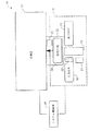
ここで図1を参照する。検査試料について診断検査を行なうために使用する自動分析装置10は、計測器12および移送装置14を備えている。計測器12は、一般的に、1994年11月10日に出願された米国特許出願第08/338,022号に記載された種類のものと同様の保温室および処理ステーション、1993年 3月19日に出願された米国特許出願第08/035,341号等に記載された種類のものと同様の発光計測器(luminometer )、並びにロボット式アームにより制御されたピペットから一般的に構成された流体搬送装置を備えている。上述した出願の各々をここに引用する。移送装置14により、無中断検査のために試料を連続的に供給できる。
【0018】
移送装置14は、供給列16、処理列18および排出列20を備えている。この供給列16は、試験管のような試料含有容器を、例えば、供給列16の一方の端部に位置する装填位置22に向かって搬送させる。この試験管は、分析装置10により分析すべき患者の体液検体等の試料を保有している。一度試験管が装填位置22に到達すると、給送(infeed)装置24が試料含有試験管を供給列16から処理列18の所定の位置まで搬送させる。
【0019】
試験管が供給列16から処理列18まで動くときに、この試験管が、供給列16の装填位置22に近接して配置されたバーコード読取器26を通過する。このバーコード読取器26は、ラベルにより各々の試験管および各々のラックに一般的に取り付けられたバーコードを解読し、その情報を、処理列18に供給された試料の追跡および試料を検査する順番の計画を含む様々な機能を果たすシステム制御器28に伝達する。
【0020】
一度試験管が試料ラック内で処理列18まで動かされると、計測器12が試験管から試料の一部を吸引し、続いて、この試料の一部を、計測器12内に配置されたキュベットのような反応容器中に計量分配する。ここで、上記出願第08/338,022号により試料の一部が処理される。
【0021】
試料が試験管から吸引され、反応容器中に計量分配された後、検査結果が得られるまで、試料ラックは一般的に処理列内に保持される。したがって、検査結果がうまく得られなかった場合には、試験管から試料の一部を吸引し、これを別の反応容器中に計量分配することにより、検査を再度行なうことができる。一度試料ラック内の各々の試料がうまく検査されると、処理列18が試料ラックを排出装置30の前に配置する。この排出装置30が試料ラックを処理列18から排出列20まで搬送させる。一度試験管が排出列20まで搬送させられると、試料含有試験管に再度使用者がアクセスでき、一般的に、これらの試験管は周期的に移送装置14から取り出される。
【0022】
処理列18は保護ハウジング32内に包囲されており、試験管が供給列16から処理列18まで動かされた後には、使用者が試料含有試験管にアクセスできないようにしている。このように、試験管が供給列16上にある間には試験管に容易にアクセスでき、任意に順番付けて配列したり、再配列したりできるが、一度試料が処理列18まで動かされると、試料の配置および順番を使用者が変えることはできない。この処理列18で、制御器が試験管の位置の記録を有している。
【0023】
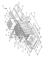
ここで図2、3、3Aおよび4を参照する。移送装置14´は、供給列16、処理列18および排出列20を備えている。複数の試料ラック33が、概して長方形の供給列16上に配置されている。各々の試料ラック33は複数の試料含有試験管34を保持するように適用されており、したがって、試料ラック33は多数の試験管34を、供給列16から処理列18まで、並びに、処理列18から排出列20まで同時に動かすことができる。
【0024】
作動中において、使用者は1つ以上の試料ラック33を供給列16上のどの位置に配置してもよい。試料ラック33が供給列16に沿って動かされている間に、使用者は試料ラック33を取り出したり、または任意の順番または所定の順番に配列しても差支えない。このように、供給列16は一般的に、自動分析装置10(図1)の、使用者に容易にアクセスされる区域である。
【0025】
供給列16は、長方形、例えば、約13.2cm(約5.2 インチ)の幅Wおよび約44.5cm(約17.5インチ)の長さLを有するトレイ38から構成されている。トレイ38の幅Wは、試料ラック33の長さを収容するように選択しなければならず、また、トレイ38の長さLは多数の試料ラック33を収容するように選択しなければならない。
【0026】
試料ラック33は、各々の試料ラック33のハンドル39が使用者に近接するトレイ38の側に位置するように、トレイの第1の表面38a 上に装填されている。ハンドル39により、使用者がトレイ38上の試料ラック33を容易に保持し、したがって、動かしたり配列させたりすることができる。
【0027】
各々の試料ラック33には、試験管34をその中に配置する複数の開口部を有する上面33a 、前端、後端および中に凹部40が形成された低面がある。
【0028】
トレイ38には、その長さに亘り隆起中央部分(以下ガイドと称する)42がある。ガイド42は、試料ラック33が供給トレイ38の第1の端部から第2の端部まで搬送するときに試料ラック33が沿って動くガイドとして機能する(図2の左から右)。
【0029】
このガイド42は、トレイ38とは別の片として設けてもよく、あるいは好ましくは、ガイド42は、アルミニウム内のプラスチックの型打ちまたはプラスチックの射出成形によりトレイ38の一体部品として設けてもよい。このガイド42は、試料ラック33がガイド42に引っ掛かったりもつれたりしないような高さを有さなければならない。
【0030】
トレイ38には、試料ラック33の後端にあるスロット46と噛み合い、試料ラック33がトレイ38から外れてしまったり、傾くのを防ぐ後端ガイド44が設けられている。
【0031】
トレイ38は、試料ラック33の駆動装置を囲むハウジング50上に配置されている。この駆動装置は、トレイ38の下側で生じる磁力により、供給トレイ38の上面に沿って試料ラック33を搬送させる。トレイ38およびハウジング50は、駆動装置を覆い、したがって、この駆動装置を使用者の環境から隔てている。
【0032】
トレイ38およびハウジング50は駆動装置を完全に囲んでいるので、駆動装置の搬送部品に使用者をさらすことによる安全上の問題が最小になる。さらに、トレイ38およびハウジング50は、流体がこぼれたり、他の望ましくない要因(例えば、埃および泥)が駆動装置、または移送装置14´が接続されて作動する分析装置の他の区域を汚すのを防ぐ。また、使用者はいかなる搬送部品にもさらされないので、使用者が怪我したり、駆動装置の作動が妨害されたりするのを防ぐために、トレイ38の洗浄前または洗浄の最中に駆動装置を停止させる必要がない。
【0033】
さらに、トレイ38の表面には開口部がないので、トレイ38は比較的洗浄しやすい。トレイ38の洗浄は、試料ラックの位置合せ構造の妨害を受けない。このことにより、移送装置14´の操作を中断せずに、試料ラック33を任意にトレイ38に装填したり、トレイ38から取り出したり、並べ変えたりすることができる。
【0034】
処理列18は、試料ラック33が供給列16から処理列18まで都合よくそして容易に搬送できるように、供給列16に隣接して配置されている。この実施の形態において、処理列18は搬送可能な運搬部材52上に取り付けられている。
【0035】
この運搬部材52上には、正方形の断面を有し、厚さが一般的に約2.54cm(約1インチ)のアルミニウム部材として設けてもよい支持ブロック54が配置されている。支持ブロック54は、スライド58を運搬部材52上から所定の距離に支持し、運搬部材52を構造的にさらに支持している。駆動装置53は、制御器28からの信号に応答して処理列18を搬送させるように接続されている。
【0036】
処理トレイ60はスライド58上に取り付けられて、処理トレイ60の底面に取り付けられたリニアベアリング上で動く。
【0037】
処理トレイ60には、そのベース表面から突出した等しい間隔で配置された複数の仕切壁61が設けられている。この仕切壁61は、試料ラック33が保持される複数のスロット64を形成する。
【0038】
給送装置51が供給列16上の所定の位置に取り付けられている。図示した実施の形態において、給送装置51がトレイ38の端部に取り付けられている。給送装置51は試料ラックを供給列16の遠い端部の装填位置から処理列18の空のスロット64まで搬送させる。この給送装置51について、図3および4を参照して詳細に記載する。処理トレイ60は、制御器28により、空のスロット64が給送装置51により供給される試料ラック33を受け入れるのに利用できることを確認にする位置に向けられている。
【0039】
処理トレイ60は一般的に、一方の端部または他方の端部に運搬器68内にあるプローブチップトレイ62を搭載している。このプローブチップトレイ62には、複数の使い捨てプローブチップ70が配列されている複数の孔66がある。
【0040】
移送装置14´はさらに、モータ駆動装置76により駆動されるプッシュロッド74を有する排出プッシャ72を備えている。このモータ駆動装置76は、スロット64を通してプッシュロッド74を駆動し、それによって、試料ラック33が、制御器28の制御下で処理列18から排出列20の排出トレイ78の表面78a 上に動かされる。
【0041】
排出トレイ78には、供給トレイ38上のガイド42と同様のガイド80がある。試料ラックが処理列へと処理列から動かされる場所には、ガイド42,44,80および99はない。一度試料ラック33が処理列18から排出列20まで動かされると、インデスク機構が排出トレイ78の上面に沿って試料ラックを搬送させる。このインデクス機構については図3Aを参照して詳細に説明する。
【0042】
この特定の実施の形態において、20の試料ラック33を保持するのに十分に長いトレイを有する供給列16を選択する。ここでは、各々の試料ラック33は5つの試験管34を保持している。
【0043】
試験管34の各々には、バーコードラベルが貼り付けられている。試験管34は、貼り付けられたバーコードラベルが供給列16のの装填位置22に近接して配置されたバーコード読取器にさらされるように、試料ラック33内で向けられている。ここで、試料ラックは処理列の外に動かされる。
【0044】
給送機構51を、1組の滑車86a,86b の周りを無限に回転するベルト64を含むものとして図示する。より明らかに図4に見られるように、第1の滑車86a がステッパモータのような二方向性モータ104 に接続されている。
【0045】
ここで再度図3を参照する。ベルト84には、複数の外側に延びたパドルまたは形材88,88a-88bが接続されている。形材88はベルト84の一部のみに配置されている。端にある形材88a,88h の位置は、試料ラック33がそれらの間の装填位置22内に置かれ、一方で、形材88b-88h が、試料ラックが形材88a と88h の間から動かされるときに、装填位置22に隣接した試料ラック33a が装填位置に進入するのを妨げるように選択する。
【0046】
ある実施の形態において、ベルト84および形材88はウレタンであり、射出成形技術を用いて一体片として製造してもよい。あるいは、形材88をベルト84とは別々の片として製造してもよい。この場合、形材を、超音波溶接または当業者によく知られた他の固定技術によりベルト84に取り付けることができる。
【0047】
装填位置22に近接した供給列16には装填位置ガイド89が接続されている。装填位置ガイド89は装填位置22内の試料ラックが傾くのを防いでいる。
【0048】
ベルト84が反時計方向に回転し、形材88を供給トレイ38上に配置された試料ラック33と反対の位置に搬送させる場合、装填位置が試料ラック33を受け入れるのに利用できる。形材88に隣接した試料ラック33が、その存在が以下に記載するセンサにより知覚される装填位置22の空間中に搬送させられる。
【0049】
モータ104 (図4)はベルト84および形材88を時計方向に駆動する。形材88a には、現在供給列16の装填位置22内に配置されている試料ラック33の第1の端部と接触するアルミニウムブロック90が接続されている。ベルト84が時計方向に動くときに、試料ラック33a が、供給トレイ38の装填位置22から、処理列18内のスロット64まで制御器28の制御下で押される。
【0050】
ブロック90は、試料ラック33の端部と接触する表面が搬送して、試料ラック33が供給列16から処理列18上まで完全に押されることを確実にする距離だけ延びる。
【0051】
処理列18は給送機構51によりそこに供給される試料ラック33を受け入れる。上述したように、処理列18は、供給列16からの試料ラック33が処理列18の異なる空間64中に供給されるように、トラックに沿って線形に動く。また、処理列18は、制御器28の制御下でトラックに沿って動き、特定の試料ラック33を排出プッシャ72と位置合せする。
【0052】
処理列18は、その試料が排出プッシャ72の前で処理列18内でうまく検査された試料ラック33を配置する。排出プッシャ72は二方向性モータ76により駆動されるプッシュロッド74を備えている。位置97で、プッシャアッセンブリ100 内のプッシャ108 (図3A)が試料ラックを排出列上に押し出す。
【0053】
排出列20の端部にあるセンサ98が、排出列20が試料ラック33で満たされると、信号を制御器28に知らせ、使用者に、試料ラック33の出口列20からの取出しのような作業を行なうことを知らせる、および/またはさらに追加の試料ラック33が、出口列20上の空間が利用できるようになるまで、処理列18から出口列20に搬送するのを防ぐ。このようなセンサは、トレイ78の上面または底面に配置してもよい。
【0054】
移送装置14´には、緊急試料ラック供給列105 が設けられている。供給列105 には、スタット供給位置101 、スタットセンサ102 およびスタット装填位置103 がある。スタット供給位列105 の目的は、使用者に、分析装置10にスタット供給列105 内に装填された試料について、できるだけ早く、順番を飛ばして検査を行なわせることにある。
【0055】
使用者が試料ラック33をスタット供給位置101 中に配置すると、スタットセンサ102 が、ベルト84の適切な側に固定された形材88により試料ラックをスタット供給位置101 からスタット装填位置103 に押し出すプッシャブロック108 (図3A)を始動させる。スタット装填位置ガイド113 がスタット装填位置103 に近接して配置され、スタット装填位置103 内の試料ラックが傾くのを防いでいる。次いで、給送装置51が試料ラックをベルト84の逆回転によりスタット装填位置103 から処理列18まで動かす。
【0056】
移送装置14´はさらに、スタット供給位置101 に近接して配置されたバーコード読取器を備えている。ここでは、バーコード読取器83の大部分は取り除かれて、プッシャバー106 およびプッシャブロック108 をよく見えるようにしている。このバーコード読取器83は、例えば、取付ブラケットとして設けられている取付部材109 によりプッシャブロック108 の上の固定位置に保持されている。バーコード読取器83は好ましくは、供給列16上の装填位置22(図3)またはスタット装填位置103 のいずれかから処理列18に動かされる試験管に貼り付けられたラベルのバーコードを読み取れるように配置されている。
【0057】
試料ラック33および試験管が供給トレイ38から処理列18まで動かされるときに、バーコードラベルがバーコード読取器83を通過して、このバーコード読取器83がバーコードラベルからの情報の暗号を解いて、そのような情報をシステム制御器28に送る(図1)。この情報には、患者、試料、および他の直接的な流体のデータを含めてもよい。各々の試料について行なうべき検査は、制御器28に別々に供給する。いくつかの試料は、バッチ内の全ての検体に関する特定の群の検査を意味する「バッチラン」と確認してもよい。
【0058】
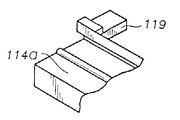
ここで、図5、5A、6、7および8を参照する。磁気コンベヤ110 に供給列18が設けられている。トレイ38の下には、駆動装置116 がある。この特定の実施の形態において、駆動装置116 は、駆動モータ119 により駆動される、1組の滑車118a,118b の周りに配置された第1および第2の駆動ベルト117 を備えている。ベルト117 は、トレイ38の前部分および後部分の近くに配置されている。
【0059】
再度、図5、5Aおよび5Bを参照する。ここでは、駆動モータ119 が、滑車キヤ118b(図5B)として設けられている滑車118bに接続された駆動ギヤ123 を有するステッパモータ119 として設けられている。接続は、2:1のギヤ減速比で行なわれている。
【0060】
点線で示す駆動装置116 の別の実施の形態において、駆動モータ119 をトレイ38の下に配置し、駆動ベルト120 を介して滑車118aに接続してもよい。
【0061】
複数の磁石アッセンブリ121a-121e が各々駆動ベルト117 に接続されている。磁石アッセンブリ121a-121e が所定の距離だけ等間隔で離れている。トレイ38は、図5に示す磁石アッセンブリ121a,121c および121eがトレイ38の下を所定の距離だけ通過するように、ベルト117 の上で所定の距離だけ離れて配置されている。各々の磁石アッセンブリ121a-121e は、磁力が少なくともトレイ38の表面114aで、この実施の形態においては好ましくはその上に発生するように、十分なおおきさの磁力を有する磁石を備えている。
【0062】
試料ラック33には、磁石アッセンブリ121 の磁力により噛み合うことのできる磁気的吸引性領域がある。この磁石アッセンブリ121 は、駆動装置が試料ラック112 をトレイ38の表面に沿って搬送させるように、試料ラック33を駆動装置に磁気的に接続している。
【0063】
この実施の形態においては、5つの磁石アッセンブリ121a-121e が、ベルト117 を介して1組の滑車118 の周りに駆動され、試料ラック112 を転写トレイ114 に沿って搬送させている。磁石アッセンブリ121 が互いに離れている距離は、限定されるものではないが、各々個々の磁石アッセンブリ121 が動かせる試料ラック33の数を含む様々な要因により選択する。この特定の実施の形態において、各々の磁石アッセンブリ121 は、いくつかの試料ラック33を動かすのに十分な磁力のものである。もちろん、より多くのまたより少ない磁石アッセンブリ121 を用いても差支えない。コンベヤ装置110 はさらに、ベースプレート126 に接続され、ベルト117 の表面の下に配置されたセンサ124 を備えている。センサ124 は、例えば、ホール効果センサとして設けてもよく、磁石アッセンブリ121 がその上を通過するときはいつも信号を生じるように配置されている。センサ124 は、磁石アッセンブリ121 の位置を示す。ベルト117 上の磁石アッセンブリ121a-121e の各々の他のものに関する位置は分かっているので、磁石アッセンブリ121 のうちの1つの位置が分かれば、磁石アッセンブリ121 の各々の位置も分かる。
【0064】
移送装置110 はさらに、例えば、隣接する試料ラック33の表面から反射する光を検出する光学センサとして設けてもよい、装填位置センサ128 を備えている。稼働中に、試料ラック33が形材88a の前の装填位置中に入るときに、試料ラック33の表面201 (図10)を光が反射して、装填位置センサ128 を始動させる。
【0065】
装填位置センサ128 により発せられた信号に応答して、滑車129 に接続された駆動モータ119 が、一般的に、3つの磁石アッセンブリ121 がセンサ124 を通過するまで、時計方向にベルト117 を回転させる。この工程により、トレイ38の左側に位置する試料ラック33がトレイ114 の全長だけ搬送することを確認する。
【0066】
次いで駆動モータ119 が所定の短い距離だけ離れて(一般的に0.06インチ)反時計方向にベルト117 を回転させて、隣接した試料ラックにより、装填位置内の試料ラックに加えられた圧力を解放する。装填位置にある試料ラックへの力を減少させることにより、給送装置51は試料ラックを供給列16(図3)から処理列18(図3)までいっそう容易に駆動できる。
【0067】
ここではベルト117 、滑車118 およびモータ119 から構成した駆動システムは完全にトレイ38および磁石アッセンブリ121 からは独立している。したがって、駆動システム116 は、電磁手段または他の手段のような磁石アッセンブリ121 を搬送させる手段により、構成してもよい。
【0068】
例えば、磁石アッセンブリは、スイッチを入れたり切ったりして、試料ラックの磁気的吸引性領域を引き付ける電磁石を有するものとして設けてもよい。このように電磁石は、ベルト117 と同様のゴンベヤ型ベルトによるか、またはトレイの下で線形方向に前後に搬送するプッシャロッドにより搬送させてもよい。プッシャロッドの手法に関して、プッシャロッドが磁石および試料ラックを装填位置の端の位置から装填位置に近接した位置まで搬送させるときに、電磁石が活性化される。次いで、プッシャロッドが装填位置から電磁石を引っ込めた後に、電磁石が不活性化される。さらに、完全に満たされた供給トレイに関して、ベルト117 上で電磁石を用いた場合には、電磁石を切って、磁力を連続的に試料ラックに対して押し付けるのを防ぐ必要はないが、むしろ、電磁石を切ってもよい。
【0069】
図6を参照する。図5に関して上述した磁石コンベヤ110 の一部の3つの試料ラック33がその上に配置された様子が示されている。各々の試料ラック33の上部分が省かれて、各々の試料ラック内に配置された試験管130 を暴露している。試料ラック33の底部分は、切り去られて、断面で、試料ラック33の底部分内に配置された板134 を露出している。この板134 は、磁気的吸引性の材料から構成してもよい。
【0070】
この特定の実施の形態において、板134 は、一般的に約3.2 mm(約0.125 インチ)の厚さを有する磁気ステンレス鋼から形成してもよい。しかしながら、別の実施の形態においては、鉄、非ステンレス鋼または磁石材料のような他の材料を用いてもよい。板134 を磁石材料から形成する場合には、板134 の磁極が磁石アッセンブリ121 の磁極とは反対ではないことを確認しなければならない。
【0071】
磁石アッセンブリ121 は、断面で示すように、受け板138 、棒磁石140 および磁石カバー142 がその上に配置されている、典型的に約2.2 mm(約0.090 インチ)の厚さを有するアルミニウムハウジング136 を備えている。受け板138 は磁気ステンレス鋼から形成され、一般的に約1.5 mm(約0.060 インチ)の厚さを有している。磁石140 は、典型的に約6.4 mm(約0.250 インチ)の厚さを有するネオジム−鉄−ホウ素磁石として用意してもよく、磁石カバー142 はアセタールのようなプラスチック材料または典型的に約1.0 mm(約0.040 インチ)の厚さを有する同様の材料から形成してもよい。
【0072】
磁石アッセンブリ121 はベルト117 の表面から突出している形材144 に接続されている。形材144 は図3および4に関して上述した形材88と同様であってもよい。
【0073】
磁石アッセンブリ121 は、形材144 内に設けられたクリアランスホールを通り、アルミニウムハウジング136 内に設けられたねじ孔と合わさるねじにより形材144 に接続されていても差支えなく、もしくは、エポキシまたは当業者に知られた溶接技術により形材144 に固定されていてもよい。
【0074】
受け板138 は、各々のベルト117 に関して復路接続アッセンブリ121 を設けることにより磁石140 により設けられた磁界の強さを増大させるように設けられている。受け板138 はまた磁石140 により形成された磁界の形状を改良する。磁石140 は、磁界が、試料ラック33がその上に配置されたトレイ38の表面のまたはその上の領域で集束するようなトレイ表面の下の距離だけ離れて配置されている。板134 の第1の縁はトレイ表面に対して直角であり、磁石アッセンブリ121 が試料ラック33を引き付けられるような比較的強い磁石対を形成している。板134 の第2の後方縁は、以下に記載するように、傾斜した表面を有するように設けられている。
【0075】
この実施の形態においては、トレイ38は、典型的に約1.6 mm(約0.0625インチ)の厚さを有するアルミニウムシートから形成されている。試料ラック33がその上に配置されているアルミニウムシートの表面には、テフロン(商標)のようなポリテトラフルオロエチレン型のコーティングがその上に形成されて、トレイ38の表面と試料ラック33の接触表面との間の摩擦力を減少させている。ベルト117 は、カバー142 の上面がトレイ表面38と接触しているかまたはその下にわずかに間隔をおいて配置されるようなトレイ表面38の下の距離だけ間隔がおかれて配置されている。
【0076】
ここで図7を参照する。ここには、供給列の装填位置に試料ラック33が配置されたコンベヤ装置110 が示されている。図7から分かるように、装填位置は、トレイ38の肩部38c により一方の側で定義されたチャンネルに対応している。装填位置ガイド150 は装填位置の近接して配置されている。作動中において、試料ラック33が供給列の装填位置中に動かされるときに、装填位置ガイド150 が試料ラック33の前端部に形成されたスロット152 と噛み合う。このガイド150 は、試料ラック33が装填位置内に適切に位置合わせされていることを確実にする。
【0077】
試料ラック33が装填位置に到達すると、センサ128 が、制御器28の制御下で給送装置51を始動し、ベルト84により形材88a および部材90(図3)を回転させて、試料ラック33を処理列上に駆動する信号を送る。形材88a を形材88の代表とすると、典型的に約2.54cm(約1インチ)の高さH、典型的に約1.9 cm(約0.750 インチ)の幅Wおよび典型的に約3.2 mm(約0.125 インチ)の厚さTを有する形材88a を用意する。形材88a の底縁89は、トレイ38の上面から所定の距離、典型的に約6.4 mm(約0.25インチ)だけ間隔が置かれて配置されている。
【0078】
上述したように、磁石アッセンブリ121 はベルト117 から突出した形材144 と接続されている。磁石アッセンブリ121 が形材88および滑車118aに近接したトレイ38の端部に近付くときに、磁石アッセンブリ121 は滑車118aの端部を越えて延ばされて、試料ラック33がトレイ38の装填位置に完全に動かされていることを確認する。このように、上述したように磁石140 を形材144 に接続することにより、磁石アッセンブリ121 が、滑車118aを回るときに、ベルト117 の端部を越えて試料ラック33を搬送させる。
【0079】
図7から分かるように、滑車118aまたは118bには、ベルト117 内の対応する凹部と噛み合い、インデキシングを保つ一連の歯がある。
【0080】
図6に関して上述したように、一度試料ラック33が装填位置の配置されると、滑車118 が回転して、ベルト117 をさらに搬送させて、トレイ114 上の他の試料ラック33を装填位置に向かって搬送させる。ベルト117 が装填位置から後ろに離れて短く動いたときに、装填位置まで搬送すべきラインにある次の試料ラックの下に制御器28により置かれた磁石アッセンブリ121 のうちの1つによりベルト117 が搬送を停止し、装填位置にある試料ラック33が装填位置内に止まっている一方で、他の試料ラック33がわずかに搬送して離れ、装填位置で滞るのを防いでいる。
【0081】
ここで図8および9を参照する。底面図において、間隔が離れておかれ、トレイ114 の対向する端部に配置された1組の同じステンレス鋼の軸162,164 を備えた駆動アッセンブリ116 が示されている。軸164 を代表とすると、軸164 の各々の端部が、トレイ114 の下に延びる取付板167a,167b のそれぞれの端部に示したように取り付けられたボールベアリングアッセンブリ166 に接続されている。このボールベアリングアッセンブリ166 により、軸162,164 が取付板167 に対して回転できる。各々の軸162,164 には、組になった駆動滑車118a,118b がその上に取付けられている。1つのベルト滑車118bの近くには、駆動ギヤ123 が配置されている。図9において、別の駆動滑車176 が、軸164 に接続され、軸182 、滑車181 およびベルト180 を介して駆動モータ177 により駆動されている。
【0082】
図9から明らかに分かるように、駆動軸162 はここでは、肩領域196 およびロッキングカラー198 の組合せにより互いに保持された1組の軸192,194 から形成されている。軸162,164 を多くの別々の片から形成することにより、軸162,164 を容易に組み立て、修理と交換のために容易にアクセスできるように容易に分解できる。
【0083】
図9から明らかに分かるように、供給列後縁ガイド44、装填ガイド89、および排出列後縁ガイド99がトレイ114 上に配置されている。
【0084】
ここで図10−17を参照する。ラック33に相当する試料ラック200 には、第1と第2の対向端200a,200b 、上面200c、底面200d(図14)および1組の対向側面200e,200f (図16)がある。必要に応じて、反射部材201 が表面200e上に配置されている。反射部材201 は、光を反射して、光学センサ128 (図5)を始動させる。このように、反射部材を、センサ128 を始動させるように位置合わせされた表面200eのどの部分に沿っても配置しても差支えない。あるいは、好ましくは、部材201 を省いて(図11)、表面200eが反射性材料から作成されているか、または、そこに入射した光を反射してセンサ128 を始動させるように研磨されている。
【0085】
複数の開口部202a-202e がラック200 の上面200eに形成されている。典型的な場合には、5つの開口部がある。開口部202a-202e は、試料含有容器を受け入れるように選択された形状を有するように設けられている。この特定の実施の形態において、開口部202 は、所定のサイズの試験管を収容するように選択された円形を有するように設けられている。各々の開口部202a-202e には、試料ラック200 の側面200eに対応するスロット204a-204e が形成されている。
【0086】
スロット204a-204e は、それぞれの開口部200a-200e の上部から試料ラック200 の底面200dに向かって延びている。開口部202a-202e 各々の内部にはフィンガースプリング206a-206e が配置されている。ここでは、開口部202 は、典型的に約4.3 cm(約1.7 インチ)の長さおよび典型的に約1.7 cm(約0.675 インチ)の直径を有するように形成されている。スプリング206 は、典型的に約3.8 cm(約1.5 インチ)の長さおよび典型的に約8.0 mm(約0.313 インチ)の幅を有するように形成され、スロットは典型的に約8.8 mm(約0.345 インチ)の幅を有するように形成されている。スロット壁205 (図11)は、典型的に約2.0 mm(約0.08インチ)の厚さを有するように形成され、スプリング206 とともに、3点で接触して(スプリング206 の中央部とスロット204 の縁の間の2つの線および点)、様々なサイズの試験管を試料ラック200 の開口部202 内に固定する。
【0087】
図18A−Cは、スプリング206 の、検査試料容器34を保持するときの取付けおよび使用中の圧縮を示す試料ラック33のスロット204 の中間から下の断面図である。各々のスロット204 の後方には、それぞれ、上部と底部に縁がついたスプリング保持溝203 および205 がある。これらの溝は、2つの溝203 および205 を構成するスロット204 の各々の側に形成されたリッジ207 により形成されている。スプリング206 には、溝203 および205 の先端を越えて滑らせることによりラック内にスプリングを維持するのに役立つ巻かれた端部208 がある。スプリング206 の圧力が加えられていない通常の位置が図18Aに示されている。このスプリングが取付け中に延ばされて、下側の巻かれた端部208 が溝205 に入るまで、底側端部208 が溝205 に達することができない。図18Cに示したように試験管を挿入する際には、力211 の下でスプリング206 にさらに圧力が加えられて、底側端部208 を溝205 のスラック収容延長部213 に下方に延ばす。試験管を取り出した際には、スプリング206 が図18Bの状態に戻る。
【0088】
試験管214 にはバーコードラベル216 が貼り付けられている。バーコードラベルが貼り付けられている試験管の一部が、スロット204aを通して露出され、したがって、読取器83に見えるようになっている。
【0089】
試料ラックは所定の範囲の直径を有する試験管を保持できるが、この範囲内において、同一の試料ラック内には同様の直径を有する試験管を配置することが好ましい。このように、以下に記載するように、各々の試料ラックは10.25 mm−16.5mmの範囲の直径を有する試験管を保持できるが、特定の範囲内の直径を有する試験管を保持する特定のラックを選定することが望ましい。
【0090】
この特定の実施の形態においては、開口部202a-202e が円形の断面形状を有するように形成されているが、他の断面形状を用いてもよい。例えば、開口部を、長方形、正方形、三角形または他の断面形状を有するように形成してもよい。また、開口部をテーパー状の壁を有するように形成して、より容易に円錐型容器を保持するようにしてもよい。中に配置する試料含有容器を容易に試料ラック200 内に配置したりそこから取り出したりできるように開口部の特定の形状を選択すべきである。さらに、開口部202a-202e 全てが同一の形状を有する必要はない。開口部の大きさおよび形状にかかわらず、上述したスプリングの形状を用いて、その中に試料含有容器を固定し、しっかりと保持することができる。
【0091】
再度図10−17を参照する。試料ラックの前端にはその中に装填スロット152 が形成されている。装填スロット152 が装填ガイド150 を受け入れて、供給列の装填位置内に試料ラック200 を適切に位置合わせする(図7および9)。
【0092】
同様に、試料ラック200 の後端には、供給列縁ガイド48と合わさり(図2、3)、列縁ガイド99から出る(図2、3)開口部がある。開口部46には、供給列上に試料ラック200 を配置するのに役立ち、ラック200 が供給列の上で傾いたり、滑るのを防ぐ供給列ガイド48上の対応する形状と噛み合う凸部222 がある。
【0093】
しかしながら、図9に関して上述したように、後縁ガイド99はL型部材として設けられている。したがって、このガイド99は、ラックを排出列から容易に取り出せるように開口部46の前部分46a のみと合わさる。
【0094】
試料ラック200 には、使用者が試料ラック200 を運ぶのに使用するハンドル224 もある。ハンドルの上部の角度のついた部分には、凹部226 が形成されて、使用者にとって掴みやすい人間工学デザインとなっている。
【0095】
ハンドル224 にも、垂直なバーコードラベル229 を取り付けてもよい側面228 がある。垂直バーコードラベル229 には複数のバーコードが配置されている。バーコードにより、試料ラック200 内に収容されている試験管のサイズ(例えば、直径範囲)を認識する。スライディングクリップ233 が試料ラック200 のハンドル224 の周りに配置されており、使用者がこのクリップ233 を適切に搬送して、試料ラック200 内に実際に配置された試験管のサイズを認識する。さらなるバーコード領域230 により試料ラックの連続番号を認識する。このように、各々個々の試料ラックには、特有の認識番号が付けられている。
【0096】
作動中に、試料ラック200 が供給列から処理列に動かされた場合にはバーコード読取器が、スライディングクリップ233 により遮断されていないかまたは強調されているラベル229 上のバーコードを読み取る。このように、バーコード読取器により、試料ラック200 内に配置された試験管の種類(すなわち、サイズ)を認識できる。上述したように、試料ラック200 は異なる直径および形状を有する試験管を保持することができる。しかしながら、試料プローブでの試験管の開口部との位置合せを改良するために、システム制御器が好ましくは試験管の種類を認識している。
【0097】
ハンドル224 を含む試料ラック200 全体を、射出成形技術により1つの部品として設けてもよい。あるいは、試料ラック200 の試験管保持部分およびハンドル224 を別々の部品として用意し、ねじ、エポキシ、または当業者によく知られた他の固定技術により互いに合わせてもよい。図11に示したように、孔231a,231b 内の1組のねじ、例えば、ねじ231c(図示せず)によりハンドル224 を試料ラック200 のベース部分に固定してもよい。
【0098】
図12から明らかに分かるように、孔202 の各々には、必要に応じて、その底部にスロット225 を形成してもよく、孔202 内に試験管を安定化してもよい。
【0099】
試料ラック200 の底面には、供給および排出列のガイド42,80 (図2)と合わさり、これらを収容する溝234 が形成されている。
【0100】
試料ラック200 の底面には、1組の長方形のキャビティ240 (図13)も形成されている。磁気的吸引性部材244 (図15)がキャビティ240 の各々の内部に配置されている。この磁気的吸引性部材は、試料ラックの底面に成形してもよい。同様に、カバー246 を部材244 の上の試料ラックに固定してもよい。この部材は、試料ラック200 の緯度の中心線245 の周りに対称的に配置されている。
【0101】
この特定の実施の形態において、磁気的吸引性部材244 の各々は、略長方形の磁気的吸引性ステンレス鋼板として設けてもよい。図15から明らかに分かるように、底面の第1の部分244cが試料ラック200 の底面からわずかに窪んでいる (または実質的に位置合せされている)。板244 の第2の部分244bは上述したようにラック200 の本体中に傾いている。
【0102】
図6に関して記載したように、作動中に、磁石アッセンブリ121 が、磁石が最初に部材244 の傾いた第2の部分244bを引き付けるような方向から試料ラックに近付く。このように、磁石アッセンブリ121 (図6)により生じた磁界の力が徐々に部材244 に導入される。
【0103】
1組のカバー246 が開口部240 の上に配置されている。これらカバー246 は、開口部240 に近接して形成された溝247 (図15)中にはまる。カバー246 は、開口部240 中のスナップフィットを形成してラック200 内の板244 を固定する一方で、部材244 の少なくとも一部を露出したままにする(図14)ようなサイズおよび形状を有するように選択される。
【0104】
この特定の実施の形態において、試料ラック部材244 は、試料ラック200 が図8のコンベヤ装置のようなコンベヤ装置のトレイ上に配置されたときに、ベルト170a,170b (図8)に接続された磁石アッセンブリ173 (図8)が部材244 の下を直接通過するように、試料ラック200 の底面に間隔がおかれて配置されている。
【0105】
試料ラック200 の底面からは、1組の凸部またはレール250,252 が突出している。レール250,252 は、列表面から部材244 とともに試料ラックの底面を、そして試料ラックが配置されている表面から部材244 を離している。このように、レール250,252 は、ラック200 が配置されているトレイ114 (図5、6)の表面と接触する試料ラック200 の表面積を減少させている。その結果、試料ラック200 とトレイ38との間の摩擦力が減少している。これにより、試料ラック200 をトレイ38に沿って動かすのに必要とされる磁力が小さてすむ。
【0106】
本発明の好ましい実施の形態を記載してきたが、本発明の概念を伴う他の実施の形態を用いてもよい。
【0107】
例えば、駆動装置に、1つのベルトおよびそれに結合した磁石を設けても差支えない。ベルトおよび磁石は好ましくは、移送トレイの中央縦軸に沿って配置される。そのような場合、試料ラックには、試料ラックの中心に配置され、試料ラックが移送トレイ上に配置されたときに1つのベルトおよび磁石と位置合せされている1つの磁気的吸引性領域がある。この場合には、試料ラックが、1つの磁石が結合される地点の周りに旋回しないように間隔の置かれたガイドによりそこから突出した1組のガイドを有するトレイを提供することが好ましい場合もある。
【0108】
さらに、試料ラックの底面に曲部を有する部材244 用の板を設けずに、各々の端部に異なる厚さを有する板を設けても差支えない。例えば、板の第1の端部が比較的薄く、板の第2の端部が比較的厚くても差支えない。駆動装置に接続された磁石は最初に、板の薄い端部と出会う。この結果、比較的弱く磁気的に接続される。次いで、磁石が比較的強い力で板の厚い端部と噛み合う。この配列により、試料ラックは静止状態から搬送状態に滑らかに移行する。
【0109】
これらの実施の形態は、開示された実施の形態に限定されるものではなく、請求項の精神および範囲のみに限定されるものである。
【図面の簡単な説明】
【図1】自動分析装置のブロック図
【図2】供給列、処理列および排出列を有する本発明による試料移送装置の1つの実施の形態を示す斜視図
【図3】試料移送装置の上面図
【図3A】試料移送装置の一部の斜視図
【図4】試料移送装置の斜視図
【図5】試料移送装置の一部の側面図
【図5A】試料移送装置の一部の詳細を示す斜視図
【図5B】試料移送装置の一部の詳細を示す上面図
【図6】試料ラックおよび磁石アッセンブリの断面図
【図7】試料移送装置の一部の側面図
【図8】駆動装置の底面図
【図9】別の駆動装置の端面図
【図10】試料ラックの斜視図
【図11】別の試料ラックの斜視図
【図12】試料ラックの上面図
【図13】試料ラックの側面図
【図14】試料ラックの底面図
【図15】磁気試料ラックの一部の断面図
【図16】試料ラックの側面図
【図17】試料ラック端面図
【図18A】スプリングの取付けおよび圧縮を示す試料ラックスロットの断面図
【図18B】スプリングの取付けおよび圧縮を示す試料ラックスロットの断面図
【図18C】スプリングの取付けおよび圧縮を示す試料ラックスロットの断面図
【符号の説明】
10 自動分析装置
12 計測器
14、110 移送装置
16 供給列
18 処理列
20 排出列
22 装填位置
24、51 給送装置
26 バーコード読取器
28 システム制御器
30 排出装置
32、50、136 ハウジング
33、200 試料ラック
34、130 試験管
38、78、114 トレイ
39、224 ハンドル
42、44、80、150 ガイド
46、64、204 スロット
52 運搬部材
53、116 駆動装置
54 支持ブロック
58 スライド
60 処理トレイ
62 プローブチップトレイ
72 プッシャ
74 プッシュロッド
83 バーコード読取器
84、117 ベルト
86、118 、129 、176 滑車
88、144 形材
98、124 、128 センサ
119 駆動モータ
121 磁石アッセンブリ
144 磁石
177 モータ
206 スプリング
229 ラベル
233 クリップ
250 、252 レール[0001]
BACKGROUND OF THE INVENTION
The present invention relates to an analyzer, and more particularly, to a transport device for taking a test sample in and out of the analyzer.
[0002]
[Prior art]
As known in the industry, automated analyzers in hospitals, clinics, laboratories, and other locations that test patient samples such as blood, spinal fluid, urine, serum, plasma, etc. There is a tendency to use. Such samples are typically placed in a container such as a sample cup, test tube, cuvette or other suitable container. One or more such containers may be arranged in a so-called sample rack.
[0003]
The sample rack is located in the loading area or supply line of the analyzer and is moved to a position where at least a portion of the sample is collected for inspection in the analyzer. After a sample has been collected for inspection in the analyzer, the sample rack is moved to a discharge or outlet row where the user can remove the sample rack from the analyzer. In this way, the user can physically place a sample rack that holds one or more samples to be examined in the loading area, and after the sample is collected, the user removes the sample rack from the discharge row. Can do. Therefore, the supply line and the discharge line of the analyzer are generally exposed to the user.
[0004]
In a typical analyzer, a sample rack is moved along the supply and discharge rows using a mechanical pusher or conveyor mechanism. In the mechanical pusher approach, the pusher device is located on a tray on which the sample rack is located. A lead screw or spring driven push block driven by a motor pushes the sample rack along the surface of the tray.
[0005]
When such mechanical pushers are used in supply and discharge trains where the impact of user interaction is significant, special care must generally be taken to ensure safe operation. For example, safety shields and safety guides are commonly used to cover the mechanical pusher, thereby preventing the user from being damaged by transport parts that would otherwise be exposed to the user. Such protective measures require additional parts in the mechanical pusher, which complicates the design of the pusher.
[0006]
Furthermore, since fluid samples are generally spilled in the supply and discharge rows, it is important that these rows can be easily cleaned. However, the above-described security measures make it difficult for the user to access the tray. Furthermore, it is undesirable for the user to clean the tray during operation of the pusher device because of the possibility of the user being hurt by the transported machine. Accordingly, the pusher device is preferably stopped so that the user cleans the supply and discharge rows in the area proximate to the pusher mechanism. This usually slows or stops the operation of the device.
[0007]
Furthermore, if there is an opening in the surface of the supply and discharge tray on which the sample rack is placed, fluid may spill into the interior of the transfer device or analyzer. Such internal areas are generally not easily accessible and if such areas are contaminated with fluid, complicated operations are required in the cleaning process.
[0008]
The conveyor type mechanism has the same problem. In a conveyor approach, a sample rack is placed on a belt that moves continuously around two or more wheels or pulleys. If a fluid sample spills on the conveying belt, this belt will carry the fluid to the interior area of the conveyor device, possibly contaminating the interior of the conveyor device or analyzer.
[0009]
A further problem with this conveyor approach is that the sample rack is transported to the end of either the supply or discharge row and stops at the stop point of the rack. However, the conveyor belt must continue to slide under the rack that stops in place at the end of the row. This may cause significant wear on the belt and the bottom surface of the sample rack that is stationary at the end of the row.
[0010]
[Problems to be solved by the invention]
Thus, moving the sample rack along the transfer tray while allowing the user to easily access the test sample in the supply and discharge rows while minimizing the possibility of user injury It is desirable to provide a sample transfer device that can be cleaned easily. The object of the present invention is to provide such a device.
[0011]
[Means for Solving the Problems]
The present invention is a transfer device for transporting a sample rack having a magnetically attractive region, wherein the drive device, a magnet connected to the drive device and transportable in response to the drive device, and a sample rack are received. A tray having an applied first surface, wherein the first surface of the magnet is such that a magnetic force applied by the magnet is present on the first surface of the tray. A transfer device is provided that is disposed on and spaced a predetermined distance therefrom. With respect to this particular arrangement, the present invention provides a magnetic conveyor device. By placing the tray on the drive, the drive mechanism is completely isolated from the user, thus minimizing safety issues. Furthermore, since the sample rack is magnetically connected to the drive device, there is no need to transport or provide slots or specific indexing areas on the surface of the tray. Even when the fluid is spilled, the internal region of the transfer device and the analyzer can be prevented from being contaminated by the fluid. Further, the tray may be made from a material that is easy to clean, thereby facilitating cleaning of the tray. For example, the tray may be made from aluminum with a Teflon coating on the surface. It is also possible to connect this tray to a cover that completely encloses the drive and protects it from spilled samples and other dirt. In addition, the tray surface on which the rack is placed is stationary, so there is no excessive wear of the sample rack due to the constant friction of the conveyor belt at the bottom of the stationary sample rack. Moreover, there are no transport parts that are exposed to the user, so this transfer device minimizes user safety issues in accessible areas such as the supply line of the analyzer.
[0012]
A rectangular tray having a length selected to hold a predetermined number of sample racks is provided. In certain embodiments, each sample rack holds one or more test tubes. The sample rack may be loaded on any part of the tray that serves as the supply line for the analyzer. The drive device located below the first surface of the tray includes a first shaft disposed below the first end of the tray and a first shaft disposed below the second different end of the tray. There are two axes. These shafts are rotatably mounted in the base. Each shaft has a set of pulleys disposed at its opposite ends. A urethane belt is disposed around the two pulley shafts facing each other. A plurality of bar magnet assemblies extend between the urethane belts. These pulley sets drive the two urethane belts and hence the magnet assembly simultaneously. The magnet assembly has a set of magnets oriented such that the opposite pole of each magnet faces the same tray surface forming a magnetic circuit that includes a magnetic field on the first surface of the tray. The magnet assembly and the first surface of the tray are closely spaced so that the magnet is free to move by the urethane belt below the surface of the tray.
[0013]
In one embodiment, each sample rack is provided with two cavities on the bottom surface. These cavities are formed on the left and right sides around the opposite side of the center line of the sample rack. Each cavity has a magnetizable plate located at the bottom of the sample rack so that when the sample rack is placed on the tray, the plate is aligned with the magnet of the magnet assembly that passes under the surface of the tray. Is placed inside. The magnetic field formed by the magnet assembly attracts the plate located on the bottom surface of the sample rack and engages the plate with sufficient force that the sample rack moves with the magnet assembly as the belt moves. When the magnet assembly first approaches the sample rack, the plate moves at a predetermined angle with respect to the magnet assembly so that the magnetic field formed by the magnet assembly is gradually generated as the belt moves to reduce acceleration towards the rear of the rack. At least a part of the first surface may be disposed. As a result, the sample rack smoothly transitions from the stationary state to the transport state.
[0014]
A sample rack having a set of rails protruding from the bottom surface is provided. These rails contact the tray and thus reduce the surface area of the sample rack which reduces the frictional force between the sample rack and the tray. A recess for receiving a guide protruding from the first surface of the tray is provided on the bottom surface of the sample rack. This guide places the sample rack along the tray. The sample rack has front and rear edge guides that prevent the sample rack from tilting while the sample rack is on the tray, ensuring that the rack is accurately aligned with the tray. The leading edge guide prevents the sample rack from tilting when the sample rack is placed in the tray loading position.
[0015]
The sample rack has an opening for receiving a sample-containing container such as a test tube. Each opening is provided with a finger spring which is placed in a compressed state when the sample-containing container is placed in the opening, and thus the sample container is fixed in the sample rack. The spring is sized so that different sized test tubes are placed and properly secured in the sample rack.
[0016]
DETAILED DESCRIPTION OF THE INVENTION
Hereinafter, the present invention will be described in detail with reference to embodiments shown in the drawings.
[0017]
Reference is now made to FIG. An
[0018]
The
[0019]
As the test tube moves from
[0020]
Once the test tube is moved to the
[0021]
After the sample is aspirated from the test tube and dispensed into the reaction vessel, the sample rack is typically held in the process row until a test result is obtained. Therefore, when the test result is not obtained successfully, the test can be performed again by sucking a part of the sample from the test tube and dispensing it into another reaction container. Once each sample in the sample rack has been successfully inspected, the
[0022]
The
[0023]
Reference is now made to FIGS. The
[0024]
In operation, the user may place one or more sample racks 33 anywhere on the
[0025]
[0026]
The sample racks 33 are loaded on the first surface 38a of the tray so that the
[0027]
Each
[0028]
The
[0029]
The
[0030]
The
[0031]
The
[0032]
Since
[0033]
Furthermore, since there is no opening on the surface of the
[0034]
The
[0035]
Located on the
[0036]
The
[0037]
The
[0038]
A
[0039]
The
[0040]
The
[0041]
The
[0042]
In this particular embodiment, a
[0043]
A barcode label is attached to each of the test tubes 34. The test tube 34 is oriented within the
[0044]
The
[0045]
Reference is again made to FIG. To the
[0046]
In one embodiment,
[0047]
A
[0048]
If the
[0049]
Motor 104 (FIG. 4) drives
[0050]
The block 90 extends a distance that ensures that the surface in contact with the end of the
[0051]
The
[0052]
The
[0053]
A
[0054]
The transfer device 14 'is provided with an emergency sample
[0055]
When the user places the
[0056]
The
[0057]
When the
[0058]
Reference is now made to Figures 5, 5A, 6, 7 and 8. A
[0059]
Referring once again to FIGS. 5, 5A and 5B. Here, the
[0060]
In another embodiment of the
[0061]
A plurality of magnet assemblies 121a-121e are connected to the
[0062]
The
[0063]
In this embodiment, five magnet assemblies 121a-121e are driven around a set of
[0064]
The
[0065]
In response to a signal generated by the
[0066]
The
[0067]
Here, the drive system comprising the
[0068]
For example, the magnet assembly may be provided as having an electromagnet that is turned on and off to attract the magnetically attractive region of the sample rack. Thus, the electromagnet may be conveyed by a Gombeya type belt similar to the
[0069]
Please refer to FIG. A portion of three
[0070]
In this particular embodiment, the
[0071]
The
[0072]
The
[0073]
The
[0074]
The
[0075]
In this embodiment, the
[0076]
Reference is now made to FIG. Here, a
[0077]
When the
[0078]
As described above, the
[0079]
As can be seen in FIG. 7, the
[0080]
As described above with reference to FIG. 6, once the
[0081]
Reference is now made to FIGS. In the bottom view, a
[0082]
As can be clearly seen from FIG. 9, the
[0083]
As can be clearly seen from FIG. 9, a supply row trailing
[0084]
Reference is now made to FIGS. The
[0085]
A plurality of openings 202a-202e are formed in the
[0086]
The slots 204a to 204e extend from the upper portions of the respective openings 200a to 200e toward the
[0087]
18A-C are cross-sectional views of the
[0088]
A bar code label 216 is attached to the test tube 214. The portion of the test tube on which the barcode label is applied is exposed through the slot 204a and is therefore visible to the
[0089]
The sample rack can hold test tubes having a predetermined range of diameters. Within this range, it is preferable to place test tubes having the same diameter in the same sample rack. Thus, as described below, each sample rack can hold a test tube having a diameter in the range of 10.25 mm to 16.5 mm, but a specific rack holding a test tube having a diameter in a specific range. It is desirable to select
[0090]
In this particular embodiment, openings 202a-202e are formed to have a circular cross-sectional shape, but other cross-sectional shapes may be used. For example, the opening may be formed to have a rectangular, square, triangular or other cross-sectional shape. Further, the conical container may be held more easily by forming the opening so as to have a tapered wall. The particular shape of the opening should be selected so that the sample-containing container placed therein can be easily placed in and removed from the
[0091]
Reference is again made to FIGS. A
[0092]
Similarly, at the rear end of the
[0093]
However, as described above with respect to FIG. 9, the trailing
[0094]
The
[0095]
The
[0096]
In operation, if the
[0097]
The
[0098]
As can be clearly seen from FIG. 12, each of the
[0099]
A
[0100]
A set of rectangular cavities 240 (FIG. 13) is also formed on the bottom surface of the
[0101]
In this particular embodiment, each of the magnetic
[0102]
As described with respect to FIG. 6, in operation, the
[0103]
A set of
[0104]
In this particular embodiment,
[0105]
From the bottom surface of the
[0106]
While preferred embodiments of the invention have been described, other embodiments with the concepts of the invention may be used.
[0107]
For example, the drive device may be provided with one belt and a magnet coupled thereto. The belt and magnet are preferably arranged along the central longitudinal axis of the transfer tray. In such a case, the sample rack has one magnetically attractive region that is located in the center of the sample rack and that is aligned with one belt and magnet when the sample rack is placed on the transfer tray. . In this case, it may be preferred that the sample rack provide a tray having a set of guides protruding therefrom by guides spaced so as not to pivot around the point where one magnet is coupled. is there.
[0108]
Further, it is possible to provide a plate having a different thickness at each end without providing a plate for the
[0109]
These embodiments are not limited to the disclosed embodiments, but are limited only to the spirit and scope of the claims.
[Brief description of the drawings]
FIG. 1 is a block diagram of an automatic analyzer.
FIG. 2 is a perspective view showing one embodiment of a sample transfer apparatus according to the present invention having a supply line, a process line and a discharge line.
FIG. 3 is a top view of the sample transfer device.
FIG. 3A is a perspective view of a part of a sample transfer device.
FIG. 4 is a perspective view of a sample transfer device.
FIG. 5 is a side view of a part of the sample transfer device.
FIG. 5A is a perspective view showing details of a part of the sample transfer device.
FIG. 5B is a top view showing details of a part of the sample transfer device.
FIG. 6 is a sectional view of a sample rack and a magnet assembly.
FIG. 7 is a side view of a part of the sample transfer device.
FIG. 8 is a bottom view of the driving device.
FIG. 9 is an end view of another driving device.
FIG. 10 is a perspective view of a sample rack.
FIG. 11 is a perspective view of another sample rack.
FIG. 12 is a top view of a sample rack.
FIG. 13 is a side view of a sample rack.
FIG. 14 is a bottom view of a sample rack.
FIG. 15 is a sectional view of a part of a magnetic sample rack.
FIG. 16 is a side view of a sample rack.
FIG. 17: End view of sample rack
18A is a cross-sectional view of a sample rack slot showing spring installation and compression. FIG.
FIG. 18B is a cross-sectional view of a sample rack slot showing spring installation and compression.
FIG. 18C is a cross-sectional view of the sample rack slot showing spring installation and compression.
[Explanation of symbols]
10 Automatic analyzer
12 Measuring instruments
14, 110 Transfer device
16 Supply column
18 Process column
20 discharge column
22 Loading position
24, 51 Feeder
26 Bar code reader
28 System controller
30 Discharge device
32, 50, 136 housing
33, 200 Sample rack
34, 130 test tubes
38, 78, 114 trays
39, 224 Handle
42, 44, 80, 150 guides
46, 64, 204 slots
52 Transport material
53, 116 Drive unit
54 Support block
58 slides
60 processing tray
62 Probe tip tray
72 Pusher
74 Push rod
83 Bar code reader
84, 117 belt
86, 118, 129, 176 pulley
88, 144 Profile
98, 124, 128 sensors
119 Drive motor
121 Magnet assembly
144 Magnet
177 motor
206 Spring
229 labels
233 clips
250, 252 rail
Claims (14)
(a) 第1と第2の端部を有する供給列、
(b) 該供給列の第2の端部に近接して配置された給送装置、
(c) 前記供給列の前記第2の端部に近接して配置された処理列、および
(d) 該処理列に近接して配置された排出列、
を有してなり、
前記供給列、処理列および排出列のうちの第1の列が、
第1と第2の対向端部および第1と第2の対向面を有する静止したトレイ、
前記静止したトレイの前記第1の表面に近接してそこから所定の距離だけ離れて配置され、前記静止したトレイの前記第1の表面上に磁力を生じることができる少なくとも1つの磁石、および
第1および第2の概ね直線的な方向で、それぞれ、前記静止したトレイの前記第1の端部から第2の端部へ、および前記静止したトレイの前記第2の端部から前記供給列、処理列および排出列の第2の列へ、前記磁石を搬送させるための、該磁石に接続された駆動装置、
を備えていることを特徴とする移送装置。 A transfer device for transferring at least one sample rack holding at least one sample container,
(a) a supply train having first and second ends;
(b) a feeding device disposed proximate to the second end of the supply row;
(c) a processing column disposed proximate to the second end of the supply column; and
(d) a discharge line disposed close to the treatment line;
Ri name have,
A first row of the supply row, the treatment row and the discharge row is
A stationary tray having first and second opposing ends and first and second opposing surfaces;
At least one magnet disposed proximate to and spaced from the first surface of the stationary tray by a predetermined distance and capable of generating a magnetic force on the first surface of the stationary tray ; and The supply row from the first end to the second end of the stationary tray and from the second end of the stationary tray, respectively, in a first and second generally linear directions ; A drive device connected to the magnet for transporting the magnet to a second row of treatment and discharge rows ;
A transfer device comprising:
第1と第2の対向端部および第1と第2の対向面を有する静止したトレイ、
該静止したトレイの近接して配置された駆動装置、
前記静止したトレイに近接して配置された磁石、および
第1および第2の概ね直線的な方向で、それぞれ、前記静止したトレイの前記第1の端部から前記第2の端部へ、および前記静止したトレイの前記第2の端部から前記供給列、処理列および排出列の第3の列へ、前記磁石を搬送させるための、該磁石に接続された駆動装置、
を備えていることを特徴とする請求項2記載の移送装置。A second column of the supply column, the processing column and the discharge column is
A stationary tray having first and second opposing ends and first and second opposing surfaces;
A drive device disposed in close proximity to the stationary tray;
A magnet disposed proximate to the stationary tray, and first and second generally linear directions , respectively, from the first end of the stationary tray to the second end; and A drive device connected to the magnet for transporting the magnet from the second end of the stationary tray to a third row of the supply row, processing row and discharge row ;
The transfer apparatus according to claim 2, further comprising:
該排出プッシャが、
少なくともその一部から突出した複数の歯を有するロッド、
試料ラックと噛み合うように適用された小歯車、および
モータの動きに応答して前記小歯車が直線方向に搬送するように該小歯車に接続されたモータ、
を含むことを特徴とする請求項3記載の移送装置。The processing line comprises a discharge pusher;
The discharge pusher
A rod having a plurality of teeth protruding from at least a part thereof,
A small gear applied to mesh with the sample rack, and a motor connected to the small gear so that the small gear is conveyed in a linear direction in response to movement of the motor,
The transfer apparatus according to claim 3, comprising:
第1の滑車、
第2の滑車、
該第1と第2の滑車の周りに配置されたベルト、
該ベルトの第1の表面から突出した複数の形材、および
前記第1および第2の滑車の周りに前記ベルトを駆動するための、前記第1と第2の滑車のうちの最初の滑車に接続されたモータ、
からなることを特徴とする請求項1記載の移送装置。The feeding device is
First pulley,
The second pulley,
A belt disposed around the first and second pulleys;
A plurality of profiles projecting from a first surface of the belt, and a first pulley of the first and second pulleys for driving the belt about the first and second pulleys; Connected motor,
The transfer device according to claim 1, comprising:
少なくとも1つの入口地点および移送地点を有し、該少なくとも1つの入口地点から該移送地点まで前記試料ラックを磁気的に搬送させる手段を備えた供給列、
該供給列の移送地点に位置合せされた入口地点および移送地点を有する処理列、
前記供給列の移送地点から前記処理列の入口地点まで前記試料ラックを搬送させる給送装置、および
前記処理列の移送地点に位置合せされた入口地点を有する排出列、
を有してなり、
前記供給列、処理列および排出列のうちの第1の列が、
第1と第2の対向端部および第1と第2の対向面を有する静止したトレイ、
前記静止したトレイの前記第1の表面に近接してそこから所定の距離だけ離れて配置され、前記静止したトレイの前記第1の表面上に磁力を生じることができる少なくとも1つの磁石、および
第1および第2の概ね直線的な方向で、それぞれ、前記静止したトレイの前記第1の端部から第2の端部へ、および前記静止したトレイの前記第2の端部から前記供給列、処理列および排出列の第2の列へ、前記磁石を搬送させるための、該磁石に接続された駆動装置、
を備えていることを特徴とする分析装置。An analyzer for analyzing a sample placed in a sample container held by a sample rack,
Has at least one entrance point and transfer point, feed the column having means for conveying said at least one of said sample racks from the entrance point to said transfer point magnetically,
A treatment line having an entry point and a transfer point aligned with the transfer point of the supply line;
A feeding device for transporting the sample rack from a transfer point of the supply line to an entrance point of the process line; and a discharge line having an inlet point aligned with the transfer point of the process line;
Ri name have,
A first row of the supply row, the treatment row and the discharge row is
A stationary tray having first and second opposing ends and first and second opposing surfaces;
At least one magnet disposed proximate to and spaced from the first surface of the stationary tray by a predetermined distance and capable of generating a magnetic force on the first surface of the stationary tray; and
The supply row from the first end to the second end of the stationary tray and from the second end of the stationary tray in first and second generally linear directions, respectively. A drive device connected to the magnet for transporting the magnet to a second row of treatment and discharge rows;
Analyzer characterized in that it comprises a.
モータ、および
該モータに接続され、該モータの回転に応答して前記試料ラックの表面と接触して該試料ラックを搬送させるプッシュロッド、
を含むことを特徴とする請求項8記載の分析装置。The second means comprises:
A push rod connected to the motor and contacting the surface of the sample rack in response to rotation of the motor to convey the sample rack;
The analyzer according to claim 8, further comprising:
前記試料ラックの第1の端部と噛み合う、前記供給列の第1の縁に沿って該供給列の第1の表面から突出した第2のガイド、および
前記試料ラックの第2の端部と噛み合う、前記供給列の第2の縁に沿って該供給列の第1の表面から突出した第3のガイド、
を備えていることを特徴とする請求項6記載の分析装置。A first guide projecting from a first surface of the supply row along a first central portion of the supply row, which meshes with a recessed area provided in a central portion of the sample rack;
A second guide projecting from a first surface of the supply row along a first edge of the supply row, meshing with a first end of the sample rack; and a second end portion of the sample rack; A third guide projecting from a first surface of the supply row along a second edge of the supply row, which meshes
The analyzer according to claim 6, further comprising:
スタット入口地点および前記処理列の入口地点と位置合せされたスタット装填地点、並びに
前記供給列および前記排出列のうちの第1の列上に配置され、前記スタット入口地点内の前記試料ラックの配置に応答する信号を送るセンサ、
を備えていることを特徴とする請求項6記載の分析装置。A first column of the supply column and the discharge column is
A stat entry point and a stat loading point aligned with the process row entry point, and a placement of the sample rack in the stat entry point disposed on a first row of the supply row and the discharge row A sensor that sends a signal in response to,
The analyzer according to claim 6, further comprising:
Applications Claiming Priority (2)
| Application Number | Priority Date | Filing Date | Title |
|---|---|---|---|
| US08/502,610 US5735387A (en) | 1995-07-14 | 1995-07-14 | Specimen rack handling system |
| US502610 | 1995-07-14 |
Publications (2)
| Publication Number | Publication Date |
|---|---|
| JPH09101314A JPH09101314A (en) | 1997-04-15 |
| JP3880659B2 true JP3880659B2 (en) | 2007-02-14 |
Family
ID=23998594
Family Applications (1)
| Application Number | Title | Priority Date | Filing Date |
|---|---|---|---|
| JP18499396A Expired - Fee Related JP3880659B2 (en) | 1995-07-14 | 1996-07-15 | Transfer device and analyzer using the same |
Country Status (6)
| Country | Link |
|---|---|
| US (1) | US5735387A (en) |
| EP (1) | EP0753747B1 (en) |
| JP (1) | JP3880659B2 (en) |
| CA (1) | CA2178296A1 (en) |
| DE (1) | DE69633485T2 (en) |
| MX (1) | MX9602285A (en) |
Families Citing this family (132)
| Publication number | Priority date | Publication date | Assignee | Title |
|---|---|---|---|---|
| JP3552810B2 (en) * | 1995-09-27 | 2004-08-11 | 松下電器産業株式会社 | Method and device for batch replacement of parts in the parts supply section |
| US6215892B1 (en) | 1995-11-30 | 2001-04-10 | Chromavision Medical Systems, Inc. | Method and apparatus for automated image analysis of biological specimens |
| US6718053B1 (en) * | 1996-11-27 | 2004-04-06 | Chromavision Medical Systems, Inc. | Method and apparatus for automated image analysis of biological specimens |
| NL1003035C2 (en) * | 1996-05-06 | 1997-11-07 | Ebm Techniek Bv | Carrier device for carrying a number of products, as well as system provided with such a carrier device. |
| KR20000065183A (en) * | 1997-03-03 | 2000-11-06 | 르네 홀저 | Carriers for Shelf Channels in Shelf Storage Systems |
| JP3413355B2 (en) * | 1997-03-31 | 2003-06-03 | 日本たばこ産業株式会社 | Automatic analysis system |
| US5904899A (en) * | 1997-05-15 | 1999-05-18 | Tosoh Corporation | Assaying apparatus and a vessel holder device in use with the assaying apparatus |
| US6141602A (en) * | 1997-09-25 | 2000-10-31 | Hitachi, Ltd. | Specimen processing system |
| US6123205A (en) * | 1997-11-26 | 2000-09-26 | Bayer Corporation | Sample tube rack |
| JP4199342B2 (en) * | 1997-12-02 | 2008-12-17 | エフ.ホフマン−ラ ロシュ アーゲー | Automatic sample processing apparatus and sample identification method in automatic sample processing apparatus |
| US6074617A (en) * | 1998-07-10 | 2000-06-13 | Bayer Corporation | Stat shuttle adapter and transport device |
| US6331437B1 (en) * | 1998-07-14 | 2001-12-18 | Bayer Corporation | Automatic handler for feeding containers into and out of an analytical instrument |
| US6132685A (en) * | 1998-08-10 | 2000-10-17 | Caliper Technologies Corporation | High throughput microfluidic systems and methods |
| EP0990906B1 (en) * | 1998-09-28 | 2006-03-15 | F. Hoffmann-La Roche Ag | Apparatus for transporting components within an automatic analyzer system |
| US6068437A (en) * | 1998-11-24 | 2000-05-30 | Lab-Interlink | Automated laboratory specimen organizer and storage unit |
| IT1310317B1 (en) * | 1999-09-15 | 2002-02-11 | Diesse Diagnostica Senese Spa | METHOD AND MEANS FOR DATA MANAGEMENT IN A LABORATORY |
| JP2001272408A (en) * | 2000-03-24 | 2001-10-05 | Olympus Optical Co Ltd | Fall prevention mechanism of sample rack |
| US6435582B1 (en) | 2000-07-31 | 2002-08-20 | Motoman, Inc. | Object manipulator and manipulation system |
| US6825041B2 (en) * | 2001-03-16 | 2004-11-30 | Beckman Coulter, Inc. | Method and system for automated immunochemistry analysis |
| US6790413B2 (en) | 2001-05-03 | 2004-09-14 | Beckman Coulter, Inc. | Sample presentation unit |
| EP1270078B1 (en) | 2001-06-22 | 2004-09-15 | Jouan Italia S.R.L. | Apparatus and method for automatic loading and unloading of centrifuge buckets |
| JP4666845B2 (en) * | 2001-09-10 | 2011-04-06 | シスメックス株式会社 | Sample transport device |
| US20030087447A1 (en) * | 2001-11-08 | 2003-05-08 | Blouin Matthew R | Sample well strip |
| AU2002361618A1 (en) * | 2001-11-13 | 2003-05-26 | Chromavision Medical Systems, Inc. | A system for tracking biological samples |
| US6571934B1 (en) | 2001-11-14 | 2003-06-03 | Dade Behring Inc. | Bi-directional magnetic sample rack conveying system |
| AU2002357107B2 (en) * | 2001-12-06 | 2008-01-10 | Biocontrol Systems, Inc. | Sample collection and testing system |
| US6752967B2 (en) * | 2002-01-04 | 2004-06-22 | Dade Behring Inc. | Stackable aliquot vessel array |
| JP3740428B2 (en) * | 2002-03-29 | 2006-02-01 | アロカ株式会社 | Sample pretreatment system |
| US7867444B2 (en) * | 2002-05-30 | 2011-01-11 | Siemens Healthcare Diagnostics, Inc. | Lab cell centrifuging module |
| US7272252B2 (en) * | 2002-06-12 | 2007-09-18 | Clarient, Inc. | Automated system for combining bright field and fluorescent microscopy |
| US20050037406A1 (en) * | 2002-06-12 | 2005-02-17 | De La Torre-Bueno Jose | Methods and apparatus for analysis of a biological specimen |
| JP4256136B2 (en) * | 2002-10-01 | 2009-04-22 | 株式会社小糸製作所 | Vehicle lighting |
| US20040202357A1 (en) * | 2003-04-11 | 2004-10-14 | Perz Cynthia B. | Silhouette image acquisition |
| US20050071110A1 (en) * | 2003-09-25 | 2005-03-31 | Davis Randall R. | Method for identifying objects to be used in an automatic clinical analyzer |
| JP4719211B2 (en) * | 2004-03-05 | 2011-07-06 | ベックマン コールター, インコーポレイテッド | Magnetic specimen transport system for automated clinical equipment |
| US7850914B2 (en) * | 2004-03-05 | 2010-12-14 | Beckman Coulter, Inc. | Specimen-transport module for a multi-instrument clinical workcell |
| US7653260B2 (en) * | 2004-06-17 | 2010-01-26 | Carl Zeis MicroImaging GmbH | System and method of registering field of view |
| US7051495B2 (en) * | 2004-06-29 | 2006-05-30 | Lifescan Scotland Limited | Method of packaging integrated biosensors |
| IL169171A0 (en) * | 2004-06-29 | 2007-07-04 | Lifescan Scotland Ltd | Manufacturing apparatus for the packaging of medical devices including integrated lancets |
| US8582924B2 (en) * | 2004-06-30 | 2013-11-12 | Carl Zeiss Microimaging Gmbh | Data structure of an image storage and retrieval system |
| JP2006191039A (en) * | 2005-01-05 | 2006-07-20 | Samsung Sdi Co Ltd | Tray transfer device |
| KR100639004B1 (en) * | 2005-01-05 | 2006-10-26 | 삼성에스디아이 주식회사 | Device for sensing and transfering of tray |
| US7628954B2 (en) | 2005-05-04 | 2009-12-08 | Abbott Laboratories, Inc. | Reagent and sample handling device for automatic testing system |
| US20070031043A1 (en) * | 2005-08-02 | 2007-02-08 | Perz Cynthia B | System for and method of intelligently directed segmentation analysis for automated microscope systems |
| JP4768409B2 (en) | 2005-11-15 | 2011-09-07 | シスメックス株式会社 | Sample analysis apparatus, sample analysis main body apparatus, and sample container supply apparatus |
| SE530192C2 (en) * | 2006-07-19 | 2008-03-25 | Hemocue Ab | Apparatus for imaging samples where the sample holder is removable by magnetic interaction |
| ES2298051B2 (en) * | 2006-07-28 | 2009-03-16 | Universidad De Malaga | ROBOTIC SYSTEM OF MINIMALLY INVASIVE SURGERY ASSISTANCE ABLE TO POSITION A SURGICAL INSTRUMENT IN RESPONSE TO THE ORDER OF A SURGEON WITHOUT FIXING THE OPERATING TABLE OR PRIOR CALIBRATION OF THE INSERT POINT. |
| JP4980671B2 (en) * | 2006-08-18 | 2012-07-18 | シスメックス株式会社 | Blood sample analyzer |
| US7731899B2 (en) | 2007-02-08 | 2010-06-08 | Biokit, S.A. | Apparatus and methods for dispensing sample holders |
| TWI325337B (en) * | 2007-07-26 | 2010-06-01 | Ind Tech Res Inst | Magnetic separation device |
| EP2255310B1 (en) | 2008-02-29 | 2019-02-20 | Dako Denmark A/S | Systems and methods for tracking and providing workflow information |
| FR2928517B1 (en) * | 2008-03-11 | 2011-10-07 | Imagene | INDUSTRIAL PROCESS FOR ENCAPSULATION OF BIOLOGICAL EQUIPMENT FOR AMBIENT TEMPERATURE CONSERVATION |
| GB0804764D0 (en) * | 2008-03-14 | 2008-04-16 | Cheyney Design & Dev Ltd | Test apparatus |
| JP2010091469A (en) * | 2008-10-09 | 2010-04-22 | Olympus Corp | Specimen dispensing device, method of dispensing specimen, and analyzer |
| KR101842708B1 (en) * | 2009-03-03 | 2018-03-27 | 에이티에스 오토메이션 툴링 시스템즈 인코포레이티드 | Multi-mode scroll cam conveyor system |
| AU2010248809B2 (en) | 2009-05-15 | 2015-07-09 | Biomerieux, Inc. | System and methods for rapid identification and/or characterization of a microbial agent in a sample |
| EP2430460B1 (en) * | 2009-05-15 | 2018-07-11 | Biomerieux, Inc | Automated transfer mechanism for microbial detection apparatus |
| JP5244062B2 (en) * | 2009-09-29 | 2013-07-24 | シスメックス株式会社 | Sample processing equipment |
| EP2299280B1 (en) | 2009-09-17 | 2019-05-08 | Sysmex Corporation | Sample processing apparatus and sample rack transporting method |
| WO2011091108A1 (en) * | 2010-01-21 | 2011-07-28 | Siemens Healthcare Diagnostics Inc. | Magnetic conveyor systems, apparatus and methods including moveable magnet |
| DE102010028769A1 (en) | 2010-05-07 | 2011-11-10 | Pvt Probenverteiltechnik Gmbh | System for transporting containers between different stations and container carriers |
| WO2012129696A1 (en) | 2011-03-31 | 2012-10-04 | Ats Automation Tooling Systems Inc. | Pallet-based position adjustment system and method |
| DE102011075039A1 (en) | 2011-04-29 | 2012-10-31 | Hamilton Bonaduz Ag | Punching device with illuminated mounting plate |
| DE102011075037A1 (en) * | 2011-04-29 | 2012-10-31 | Hamilton Bonaduz Ag | Punching device with mounting plate |
| DE102011075036A1 (en) | 2011-04-29 | 2012-10-31 | Hamilton Bonaduz Ag | Punching device with gripping unit |
| HUP1100493A2 (en) | 2011-09-08 | 2013-04-29 | Diagon Kft | Method and device for conveying sample stands |
| EP2574933A1 (en) | 2011-09-29 | 2013-04-03 | F. Hoffmann-La Roche AG | Handling of sample tubes comprising geometric tube data |
| EP2589968A1 (en) | 2011-11-04 | 2013-05-08 | Roche Diagnostics GmbH | Laboratory sample distribution system, laboratory system and method of operating |
| EP2589967A1 (en) | 2011-11-04 | 2013-05-08 | Roche Diagnostics GmbH | Laboratory sample distribution system and corresponding method of operation |
| EP2589966A1 (en) | 2011-11-04 | 2013-05-08 | Roche Diagnostics GmbH | Laboratory sample distribution system and corresponding method of operation |
| US9381524B2 (en) | 2011-11-08 | 2016-07-05 | Becton, Dickinson And Company | System and method for automated sample preparation |
| EP2852823A4 (en) * | 2012-05-22 | 2016-02-24 | Siemens Healthcare Diagnostics | Linear random access queue |
| US9446406B2 (en) | 2012-06-29 | 2016-09-20 | Biocontrol Systems, Inc. | Sample collection and bioluminescent analysis system |
| DE102014202843B3 (en) | 2014-02-17 | 2014-11-06 | Roche Pvt Gmbh | Transport device, sample distribution system and laboratory automation system |
| DE102014202838B3 (en) | 2014-02-17 | 2014-11-06 | Roche Pvt Gmbh | Transport device, sample distribution system and laboratory automation system |
| EP2927163B1 (en) | 2014-03-31 | 2018-02-28 | Roche Diagnostics GmbH | Vertical conveyor, sample distribution system and laboratory automation system |
| EP2927168A1 (en) | 2014-03-31 | 2015-10-07 | Roche Diagniostics GmbH | Transport device, sample distribution system and laboratory automation system |
| EP2927695B1 (en) | 2014-03-31 | 2018-08-22 | Roche Diagniostics GmbH | Sample distribution system and laboratory automation system |
| EP2927167B1 (en) | 2014-03-31 | 2018-04-18 | F. Hoffmann-La Roche AG | Dispatch device, sample distribution system and laboratory automation system |
| EP2927625A1 (en) | 2014-03-31 | 2015-10-07 | Roche Diagniostics GmbH | Sample distribution system and laboratory automation system |
| EP2957914B1 (en) | 2014-06-17 | 2018-01-03 | Roche Diagnostics GmbH | Laboratory sample distribution system and laboratory automation system |
| EP2977766A1 (en) | 2014-07-24 | 2016-01-27 | Roche Diagniostics GmbH | Laboratory sample distribution system and laboratory automation system |
| EP2995960B1 (en) | 2014-09-09 | 2020-07-15 | Roche Diagniostics GmbH | Laboratory sample distribution system and method for calibrating magnetic sensors |
| EP2995580A1 (en) | 2014-09-09 | 2016-03-16 | Roche Diagniostics GmbH | Laboratory sample distribution system and laboratory automation system |
| US9952242B2 (en) * | 2014-09-12 | 2018-04-24 | Roche Diagnostics Operations, Inc. | Laboratory sample distribution system and laboratory automation system |
| EP2995958A1 (en) | 2014-09-15 | 2016-03-16 | Roche Diagniostics GmbH | Method of operating a laboratory sample distribution system, laboratory sample distribution system and laboratory automation system |
| EP3006943B1 (en) | 2014-10-07 | 2020-04-22 | Roche Diagniostics GmbH | Module for a laboratory sample distribution system, laboratory sample distribution system and laboratory automation system |
| EP3016116A1 (en) | 2014-11-03 | 2016-05-04 | Roche Diagniostics GmbH | Printed circuit board arrangement, coil for a laboratory sample distribution system, laboratory sample distribution system and laboratory automation system |
| CN107431788B (en) * | 2015-02-18 | 2020-12-08 | 西门子医疗保健诊断公司 | Method and system for image-based tray alignment and tube slot positioning in a vision system |
| EP3070479B1 (en) | 2015-03-16 | 2019-07-03 | Roche Diagniostics GmbH | Transport carrier, laboratory cargo distribution system and laboratory automation system |
| EP3537160B1 (en) | 2015-03-23 | 2020-08-12 | Roche Diagnostics GmbH | Laboratory sample distribution system and laboratory automation system |
| EP3096146A1 (en) | 2015-05-22 | 2016-11-23 | Roche Diagniostics GmbH | Method of operating a laboratory sample distribution system, laboratory sample distribution system and laboratory automation system |
| EP3096145B1 (en) | 2015-05-22 | 2019-09-04 | Roche Diagniostics GmbH | Method of operating a laboratory automation system and laboratory automation system |
| EP3095739A1 (en) | 2015-05-22 | 2016-11-23 | Roche Diagniostics GmbH | Method of operating a laboratory sample distribution system, laboratory sample distribution system and laboratory automation system |
| EP3312614A4 (en) * | 2015-06-22 | 2019-06-05 | Shenzhen Mindray Bio-Medical Electronics | Sample analyzer |
| EP3314224A4 (en) | 2015-06-26 | 2019-05-15 | Abbott Laboratories | Reaction vessel moving member for moving reaction vessels from a processing track to a rotating device in a diagnostic analyzer |
| WO2016210420A1 (en) | 2015-06-26 | 2016-12-29 | Abbott Laboratories | Reaction vessel exchanger device for a diagnostic analyzer |
| EP3112874A1 (en) | 2015-07-02 | 2017-01-04 | Roche Diagnostics GmbH | Storage module, method of operating a laboratory automation system and laboratory automation system |
| EP3121603A1 (en) | 2015-07-22 | 2017-01-25 | Roche Diagnostics GmbH | Sample container carrier, laboratory sample distribution system and laboratory automation system |
| EP3139175B1 (en) | 2015-09-01 | 2021-12-15 | Roche Diagnostics GmbH | Laboratory cargo distribution system, laboratory automation system and method of operating a laboratory cargo distribution system |
| EP3153867B1 (en) | 2015-10-06 | 2018-11-14 | Roche Diagniostics GmbH | Method of configuring a laboratory automation system, laboratory sample distribution system and laboratory automation system |
| EP3153866A1 (en) | 2015-10-06 | 2017-04-12 | Roche Diagnostics GmbH | Method of determining a handover position and laboratory automation system |
| EP3156352B1 (en) | 2015-10-13 | 2019-02-27 | Roche Diagniostics GmbH | Laboratory sample distribution system and laboratory automation system |
| EP3156353B1 (en) | 2015-10-14 | 2019-04-03 | Roche Diagniostics GmbH | Method of rotating a sample container carrier, laboratory sample distribution system and laboratory automation system |
| EP3211429A1 (en) | 2016-02-26 | 2017-08-30 | Roche Diagnostics GmbH | Transport device having a tiled driving surface |
| EP3211428A1 (en) | 2016-02-26 | 2017-08-30 | Roche Diagnostics GmbH | Transport device unit for a laboratory sample distribution system |
| EP3211430A1 (en) | 2016-02-26 | 2017-08-30 | Roche Diagnostics GmbH | Transport device with base plate modules |
| WO2017207657A1 (en) | 2016-06-03 | 2017-12-07 | Roche Diagnostics Gmbh | Laboratory sample distribution system and laboratory automation system |
| EP3255519B1 (en) | 2016-06-09 | 2019-02-20 | Roche Diagniostics GmbH | Laboratory sample distribution system and method of operating a laboratory sample distribution system |
| EP3260867A1 (en) | 2016-06-21 | 2017-12-27 | Roche Diagnostics GmbH | Method of setting a handover position and laboratory automation system |
| JP6752350B2 (en) | 2016-08-04 | 2020-09-09 | エフ.ホフマン−ラ ロシュ アーゲーF. Hoffmann−La Roche Aktiengesellschaft | Laboratory sample distribution system and laboratory automation system |
| EP3330717B1 (en) | 2016-12-01 | 2022-04-06 | Roche Diagnostics GmbH | Laboratory sample distribution system and laboratory automation system |
| CN106706941B (en) * | 2016-12-16 | 2018-07-06 | 宁波美康盛德生物科技有限公司 | Multiple sample introduction propulsive mechanism |
| EP3343232B1 (en) | 2016-12-29 | 2021-09-15 | Roche Diagnostics GmbH | Laboratory sample distribution system and laboratory automation system |
| EP3355065B1 (en) | 2017-01-31 | 2021-08-18 | Roche Diagnostics GmbH | Laboratory sample distribution system and laboratory automation system |
| EP3357842B1 (en) | 2017-02-03 | 2022-03-23 | Roche Diagnostics GmbH | Laboratory automation system |
| EP3410123B1 (en) | 2017-06-02 | 2023-09-20 | Roche Diagnostics GmbH | Method of operating a laboratory sample distribution system, laboratory sample distribution system and laboratory automation system |
| EP3428653B1 (en) | 2017-07-13 | 2021-09-15 | Roche Diagnostics GmbH | Method of operating a laboratory sample distribution system, laboratory sample distribution system and laboratory automation system |
| EP3456415B1 (en) | 2017-09-13 | 2021-10-20 | Roche Diagnostics GmbH | Sample container carrier, laboratory sample distribution system and laboratory automation system |
| EP3457144B1 (en) | 2017-09-13 | 2021-10-20 | Roche Diagnostics GmbH | Sample container carrier, laboratory sample distribution system and laboratory automation system |
| CN109580970B (en) * | 2017-09-29 | 2022-07-15 | 深圳市新产业生物医学工程股份有限公司 | Sample rack loading system, loading method and chemiluminescence detector |
| ES2814448T3 (en) * | 2017-11-17 | 2021-03-29 | Mettler Toledo Llc | Radiographic inspection system with reject container |
| EP3537159B1 (en) | 2018-03-07 | 2022-08-31 | Roche Diagnostics GmbH | Method of operating a laboratory sample distribution system, laboratory sample distribution system and laboratory automation system |
| EP3540443B1 (en) | 2018-03-16 | 2023-08-30 | Roche Diagnostics GmbH | Laboratory system, laboratory sample distribution system and laboratory automation system |
| CN110683327B (en) * | 2018-07-04 | 2022-08-05 | 深圳迈瑞生物医疗电子股份有限公司 | Sample rack scheduling mechanism and method |
| CN109436651B (en) * | 2018-12-03 | 2020-06-05 | 深圳市联新移动医疗科技有限公司 | Western medicine delivery device and system |
| EP4001178A1 (en) * | 2020-11-17 | 2022-05-25 | Uhlmann Pac-Systeme GmbH & Co. KG | Conveyor device and method for conveying piece goods |
| US11747356B2 (en) | 2020-12-21 | 2023-09-05 | Roche Diagnostics Operations, Inc. | Support element for a modular transport plane, modular transport plane, and laboratory distribution system |
| CN113753487B (en) * | 2021-09-07 | 2023-05-05 | 中科计算技术西部研究院 | Automatic tube connecting placement control system and control method |
| US20230341430A1 (en) * | 2022-04-25 | 2023-10-26 | Telesis Bio Inc. | Apparatus for delivery of laboratory consumables |
| KR102635366B1 (en) * | 2023-05-23 | 2024-02-08 | 주식회사 제놀루션 | Sample processing device and sample processing method |
| CN117228303B (en) * | 2023-11-10 | 2024-03-08 | 赣州富尔特电子股份有限公司 | Arrangement conveying device for processing neodymium iron boron cylindrical section bar |
Family Cites Families (60)
| Publication number | Priority date | Publication date | Assignee | Title |
|---|---|---|---|---|
| US2609915A (en) * | 1949-03-10 | 1952-09-09 | Burgh Albert R De | Conveying apparatus |
| US2824638A (en) * | 1954-06-25 | 1958-02-25 | Burgh Raymond J De | Magnetic conveyor |
| JPS536428B1 (en) * | 1969-02-19 | 1978-03-08 | ||
| JPS5112908B1 (en) * | 1970-07-27 | 1976-04-23 | ||
| GB1393268A (en) * | 1972-12-19 | 1975-05-07 | Philips Electronic Associated | Magnetic conveyor |
| US3854602A (en) * | 1973-08-27 | 1974-12-17 | Coulter Electronics | Magnetic hopper system |
| US3985507A (en) * | 1975-09-05 | 1976-10-12 | International Business Machines Corporation | Automatic test sample handling system |
| US4088254A (en) * | 1976-12-08 | 1978-05-09 | Hooper Joel Ray | Magnetic holding apparatus and methods of constructing and utilizing same |
| US4228831A (en) * | 1978-12-11 | 1980-10-21 | Abbott Laboratories | Probe and syringe drive apparatus |
| DE3070333D1 (en) * | 1979-11-13 | 1985-04-25 | Technicon Instr | Test-tube assembly, kit for making it and method of manual immunoassay |
| DE3030396C2 (en) * | 1980-08-12 | 1984-09-20 | Bodenseewerk Perkin-Elmer & Co GmbH, 7770 Überlingen | Device for automatically feeding samples to the measuring loop of a liquid chromatograph |
| FR2499647B1 (en) * | 1981-02-06 | 1989-03-03 | Nova Scotia Res Found | IMPROVEMENTS ON HERMETIC MAGNETIC COUPLINGS |
| DE3267952D1 (en) * | 1981-03-21 | 1986-01-30 | Vacuumschmelze Gmbh | Magnetic drive system for producing linear movements |
| ES275136Y (en) * | 1981-07-20 | 1984-10-01 | American Hospital Supply Corporation | ANCHORING DEVICE FOR PELDANS IN CONCRETE PIECES OR SIMILAR. |
| JPS58102162A (en) * | 1981-12-15 | 1983-06-17 | Olympus Optical Co Ltd | Method of feeding rack to automatic analyzer |
| DE3246274C2 (en) * | 1981-12-14 | 1985-05-30 | Olympus Optical Co., Ltd., Tokio/Tokyo | Analyzer working with immunological agglutination reaction |
| JPS58154204U (en) * | 1982-04-07 | 1983-10-15 | 株式会社東京クリニカルラボラトリ− | Sample bottle automatic transfer device |
| US4526754A (en) * | 1982-07-30 | 1985-07-02 | Technicon Instruments Corporation | Sample transport system |
| US4609017A (en) * | 1983-10-13 | 1986-09-02 | Coulter Electronics, Inc. | Method and apparatus for transporting carriers of sealed sample tubes and mixing the samples |
| DE3405292A1 (en) * | 1984-02-15 | 1985-09-05 | Eppendorf Gerätebau Netheler + Hinz GmbH, 2000 Hamburg | METHOD FOR CARRYING OUT SAMPLES AND RACK FOR CARRYING OUT THE METHOD |
| JPH0761814B2 (en) * | 1984-09-10 | 1995-07-05 | 三菱化学株式会社 | Carrier |
| JPS61217343A (en) * | 1985-03-18 | 1986-09-26 | 二和印刷株式会社 | Packaging paperboard carton and manufacture thereof |
| US4678752A (en) * | 1985-11-18 | 1987-07-07 | Becton, Dickinson And Company | Automatic random access analyzer |
| JPS6340532A (en) * | 1986-04-05 | 1988-02-20 | 日本光電工業株式会社 | Apparatus for monitoring blood component |
| JPH0795070B2 (en) * | 1986-06-10 | 1995-10-11 | 東ソー株式会社 | Adsorption heads for transporting reaction cups used in biochemical reaction measuring devices |
| JPS6315164A (en) * | 1986-07-07 | 1988-01-22 | Tosoh Corp | Test pack selective supply apparatus of biochemical analyzer |
| US4900513A (en) * | 1986-07-11 | 1990-02-13 | Beckman Instruments, Inc. | Sample loading apparatus |
| JPS63141457U (en) * | 1987-03-06 | 1988-09-19 | ||
| JPH0548130Y2 (en) * | 1987-03-06 | 1993-12-20 | ||
| US4956148A (en) * | 1987-04-22 | 1990-09-11 | Abbott Laboratories | Locking rack and disposable sample cartridge |
| US5035861A (en) * | 1987-04-22 | 1991-07-30 | Abbott Laboratories | Locking rack and disposable sample cartridge |
| JPS63286769A (en) * | 1987-05-20 | 1988-11-24 | Kyoto Daiichi Kagaku:Kk | Continuous automatic analyzer using rack and rack transfer device |
| US4861553A (en) * | 1987-06-11 | 1989-08-29 | Technicon Instruments Corporation | Automatic sampling system |
| US4944924A (en) * | 1987-06-11 | 1990-07-31 | Technicon Instruments Corporation | Test tube holder |
| US4953684A (en) * | 1987-07-17 | 1990-09-04 | The West Company, Incorporated | Stopper elevator conveyor |
| US4943416A (en) * | 1987-09-23 | 1990-07-24 | Kabushiki Kaisha Marukomu | Automatic urinalysis system |
| DE3740172A1 (en) * | 1987-10-26 | 1989-05-11 | Rosy B Versand Gmbh | DRIVE SHAFT WITH A CLUTCH ARRANGEMENT |
| JP2707088B2 (en) * | 1987-11-20 | 1998-01-28 | 株式会社ニッテク | Container transfer method and apparatus |
| JPH01126565U (en) * | 1988-02-22 | 1989-08-29 | ||
| US5089424A (en) * | 1988-06-14 | 1992-02-18 | Abbott Laboratories | Method and apparatus for heterogeneous chemiluminescence assay |
| US5320808A (en) * | 1988-08-02 | 1994-06-14 | Abbott Laboratories | Reaction cartridge and carousel for biological sample analyzer |
| ES2085854T3 (en) * | 1988-08-02 | 1996-06-16 | Abbott Lab | METHOD AND DEVICE FOR THE PRODUCTION OF CALIBRATION DATA FOR ANALYSIS. |
| US5008082A (en) * | 1988-08-25 | 1991-04-16 | Eastman Kodak Company | Analyzers using linear sample trays with random access |
| US5104808A (en) * | 1988-08-26 | 1992-04-14 | Laska Paul F | Method and apparatus for effecting a plurality of assays on a plurality of samples in an automatic analytical device |
| US5012669A (en) * | 1988-10-03 | 1991-05-07 | Panametrics, Inc. | Oxygen sensing method and apparatus |
| DE3836163A1 (en) * | 1988-10-24 | 1990-04-26 | Berthold Lab Prof R | RECORDING SYSTEM FOR SEVERAL SAMPLE VESSELS FOR CARRYING OUT RADIATION MEASUREMENTS |
| US5059393A (en) * | 1989-01-05 | 1991-10-22 | Eastman Kodak Company | Analysis slide positioning apparatus and method for a chemical analyzer |
| JPH0625449Y2 (en) * | 1989-06-30 | 1994-07-06 | 照明 伊藤 | Belt conveyor type test tube carrier |
| US5178834A (en) * | 1989-07-19 | 1993-01-12 | Tosoh Corporation | Automatic immunoassay analyzer |
| CA2020480C (en) * | 1989-08-24 | 1997-11-18 | Michael P. Smith | Determining collective fluid inclusion volatiles compositions for inclusion composition mapping of earth's subsurface |
| US4981208A (en) * | 1990-02-16 | 1991-01-01 | The Cambridge Wire Cloth Company | Magnetic drive spiral conveyor system |
| JP2867174B2 (en) * | 1990-09-25 | 1999-03-08 | 東亜医用電子株式会社 | Sampler for multiple samples |
| JPH0736284Y2 (en) * | 1990-10-05 | 1995-08-16 | 東亜医用電子株式会社 | Sample identification code reader for sample container |
| US5324481A (en) * | 1991-06-03 | 1994-06-28 | Abbott Laboratories | Carousel for assay specimen carrier |
| JPH05264413A (en) * | 1992-03-17 | 1993-10-12 | Fujikura Ltd | Method and apparatus for forming meniscus liquid surface |
| US5366697A (en) * | 1992-03-30 | 1994-11-22 | Eastman Kodak Company | Tray and magnetic conveyor |
| EP0565166B1 (en) * | 1992-03-30 | 1998-11-11 | Johnson & Johnson Clinical Diagnostics, Inc. | Sample tube tray and magnetic conveyor |
| JPH0592732U (en) * | 1992-04-24 | 1993-12-17 | 株式会社ニッテク | Rack structure |
| US5244633A (en) * | 1992-05-22 | 1993-09-14 | Eastman Kodak Company | Analyzer incubator with plural independently driven rings supporting cuvettes |
| JPH0634642A (en) * | 1992-07-20 | 1994-02-10 | Nittec Co Ltd | Vessel transfer equipment |
-
1995
- 1995-07-14 US US08/502,610 patent/US5735387A/en not_active Expired - Lifetime
-
1996
- 1996-06-05 CA CA002178296A patent/CA2178296A1/en not_active Abandoned
- 1996-06-11 MX MX9602285A patent/MX9602285A/en unknown
- 1996-07-12 DE DE69633485T patent/DE69633485T2/en not_active Expired - Lifetime
- 1996-07-12 EP EP96305155A patent/EP0753747B1/en not_active Expired - Lifetime
- 1996-07-15 JP JP18499396A patent/JP3880659B2/en not_active Expired - Fee Related
Also Published As
| Publication number | Publication date |
|---|---|
| EP0753747B1 (en) | 2004-09-29 |
| DE69633485D1 (en) | 2004-11-04 |
| JPH09101314A (en) | 1997-04-15 |
| DE69633485T2 (en) | 2005-11-17 |
| MX9602285A (en) | 1997-01-31 |
| US5735387A (en) | 1998-04-07 |
| CA2178296A1 (en) | 1997-01-15 |
| EP0753747A2 (en) | 1997-01-15 |
| EP0753747A3 (en) | 1998-01-07 |
Similar Documents
| Publication | Publication Date | Title |
|---|---|---|
| JP3880659B2 (en) | Transfer device and analyzer using the same | |
| JP3880658B2 (en) | Sample rack and apparatus and method for moving the same | |
| US7850914B2 (en) | Specimen-transport module for a multi-instrument clinical workcell | |
| EP1721171B1 (en) | Magnetically attractive specimen-container rack for automated clinical instrument | |
| US7331474B2 (en) | Specimen-container rack for automated clinical instrument | |
| AU671663B2 (en) | Assay module transport apparatus for use in an automated analytical instrument | |
| US7028831B2 (en) | Magnetic specimen-transport system for automated clinical instrument | |
| JP2005509172A (en) | Bidirectional magnetic sample rack transport system | |
| CA1337247C (en) | Analyzers using linear sample trays with random access | |
| CA2143285A1 (en) | Automated chemical analyzer with apparatus and method for conveying and temporary storage of sample tubes | |
| EP2232272A2 (en) | Automatic loading of sample tubes for clinical analyzer | |
| HU223869B1 (en) | An automated apparatus for subjecting samples to one or more selected test procedures at respective test stations | |
| KR20160040138A (en) | Gripping mechanism | |
| JP6573524B2 (en) | Sample rack transport apparatus and automatic analysis system | |
| JP2017037038A (en) | Specimen rack transport apparatus and automatic analysis system | |
| JP2006292696A (en) | Specimen rack and adaptor for the same | |
| JP7321179B2 (en) | locking structure | |
| JPH0378583B2 (en) | ||
| JPS62218870A (en) | Container conveying method in automatic analysing apparatus and its apparatus | |
| CA2047072C (en) | Device for moving and positioning pipette trays in an analyzer | |
| JP5321324B2 (en) | Automatic analyzer capable of switching reaction vessel supply means |
Legal Events
| Date | Code | Title | Description |
|---|---|---|---|
| A977 | Report on retrieval |
Free format text: JAPANESE INTERMEDIATE CODE: A971007 Effective date: 20051101 |
|
| A131 | Notification of reasons for refusal |
Free format text: JAPANESE INTERMEDIATE CODE: A131 Effective date: 20060620 |
|
| A521 | Written amendment |
Free format text: JAPANESE INTERMEDIATE CODE: A523 Effective date: 20060920 |
|
| TRDD | Decision of grant or rejection written | ||
| A01 | Written decision to grant a patent or to grant a registration (utility model) |
Free format text: JAPANESE INTERMEDIATE CODE: A01 Effective date: 20061017 |
|
| A61 | First payment of annual fees (during grant procedure) |
Free format text: JAPANESE INTERMEDIATE CODE: A61 Effective date: 20061108 |
|
| R150 | Certificate of patent or registration of utility model |
Free format text: JAPANESE INTERMEDIATE CODE: R150 |
|
| FPAY | Renewal fee payment (event date is renewal date of database) |
Free format text: PAYMENT UNTIL: 20101117 Year of fee payment: 4 |
|
| FPAY | Renewal fee payment (event date is renewal date of database) |
Free format text: PAYMENT UNTIL: 20101117 Year of fee payment: 4 |
|
| FPAY | Renewal fee payment (event date is renewal date of database) |
Free format text: PAYMENT UNTIL: 20111117 Year of fee payment: 5 |
|
| LAPS | Cancellation because of no payment of annual fees |