JP3870759B2 - Optical disc recording method and optical disc apparatus - Google Patents
Optical disc recording method and optical disc apparatus Download PDFInfo
- Publication number
- JP3870759B2 JP3870759B2 JP2001348166A JP2001348166A JP3870759B2 JP 3870759 B2 JP3870759 B2 JP 3870759B2 JP 2001348166 A JP2001348166 A JP 2001348166A JP 2001348166 A JP2001348166 A JP 2001348166A JP 3870759 B2 JP3870759 B2 JP 3870759B2
- Authority
- JP
- Japan
- Prior art keywords
- data
- recording
- recorded
- optical disc
- laser
- Prior art date
- Legal status (The legal status is an assumption and is not a legal conclusion. Google has not performed a legal analysis and makes no representation as to the accuracy of the status listed.)
- Expired - Fee Related
Links
Images


Classifications
-
- G—PHYSICS
- G11—INFORMATION STORAGE
- G11B—INFORMATION STORAGE BASED ON RELATIVE MOVEMENT BETWEEN RECORD CARRIER AND TRANSDUCER
- G11B7/00—Recording or reproducing by optical means, e.g. recording using a thermal beam of optical radiation by modifying optical properties or the physical structure, reproducing using an optical beam at lower power by sensing optical properties; Record carriers therefor
- G11B7/12—Heads, e.g. forming of the optical beam spot or modulation of the optical beam
- G11B7/125—Optical beam sources therefor, e.g. laser control circuitry specially adapted for optical storage devices; Modulators, e.g. means for controlling the size or intensity of optical spots or optical traces
- G11B7/126—Circuits, methods or arrangements for laser control or stabilisation
- G11B7/1267—Power calibration
-
- G—PHYSICS
- G11—INFORMATION STORAGE
- G11B—INFORMATION STORAGE BASED ON RELATIVE MOVEMENT BETWEEN RECORD CARRIER AND TRANSDUCER
- G11B27/00—Editing; Indexing; Addressing; Timing or synchronising; Monitoring; Measuring tape travel
- G11B27/36—Monitoring, i.e. supervising the progress of recording or reproducing
-
- G—PHYSICS
- G11—INFORMATION STORAGE
- G11B—INFORMATION STORAGE BASED ON RELATIVE MOVEMENT BETWEEN RECORD CARRIER AND TRANSDUCER
- G11B7/00—Recording or reproducing by optical means, e.g. recording using a thermal beam of optical radiation by modifying optical properties or the physical structure, reproducing using an optical beam at lower power by sensing optical properties; Record carriers therefor
- G11B7/004—Recording, reproducing or erasing methods; Read, write or erase circuits therefor
- G11B7/0045—Recording
- G11B7/00458—Verification, i.e. checking data during or after recording
-
- G—PHYSICS
- G11—INFORMATION STORAGE
- G11B—INFORMATION STORAGE BASED ON RELATIVE MOVEMENT BETWEEN RECORD CARRIER AND TRANSDUCER
- G11B7/00—Recording or reproducing by optical means, e.g. recording using a thermal beam of optical radiation by modifying optical properties or the physical structure, reproducing using an optical beam at lower power by sensing optical properties; Record carriers therefor
- G11B7/12—Heads, e.g. forming of the optical beam spot or modulation of the optical beam
- G11B7/125—Optical beam sources therefor, e.g. laser control circuitry specially adapted for optical storage devices; Modulators, e.g. means for controlling the size or intensity of optical spots or optical traces
- G11B7/126—Circuits, methods or arrangements for laser control or stabilisation
- G11B7/1263—Power control during transducing, e.g. by monitoring
-
- G—PHYSICS
- G11—INFORMATION STORAGE
- G11B—INFORMATION STORAGE BASED ON RELATIVE MOVEMENT BETWEEN RECORD CARRIER AND TRANSDUCER
- G11B2220/00—Record carriers by type
- G11B2220/20—Disc-shaped record carriers
- G11B2220/21—Disc-shaped record carriers characterised in that the disc is of read-only, rewritable, or recordable type
- G11B2220/215—Recordable discs
- G11B2220/218—Write-once discs
-
- G—PHYSICS
- G11—INFORMATION STORAGE
- G11B—INFORMATION STORAGE BASED ON RELATIVE MOVEMENT BETWEEN RECORD CARRIER AND TRANSDUCER
- G11B2220/00—Record carriers by type
- G11B2220/20—Disc-shaped record carriers
- G11B2220/25—Disc-shaped record carriers characterised in that the disc is based on a specific recording technology
- G11B2220/2537—Optical discs
- G11B2220/2562—DVDs [digital versatile discs]; Digital video discs; MMCDs; HDCDs
Description
【0001】
【発明の属する技術分野】
本発明は、光ディスク装置に関わるものであり、一連のデータを連続して記録する場合に生じる問題を解消するための技術を提供するものである。
【0002】
【従来の技術】
従来の光ディスク装置では、規格に定められた記録方法に従って記録を行っていた。しかしながら、規格通りの記録方法ではディスクの種類、装置の形態、あるいはディスクに記録するデータによっては問題が生じる場合があった。その問題点について以下説明する。
【0003】
一般にディスクのレーザー光に対する感度はディスク全面に亘って均一でない。また、レーザーは、それ自体が発する熱や装置内の回路から発生する熱等によって周辺温度の影響を受け、出力が変化するという特性がある。したがって、記録中は適度なときに記録したデータの記録品質を評価し、その結果をレーザーの出力に反映させる必要がある。このことを踏まえ、規格に定められたDisc at Onceという記録方法とその問題点について説明する。
【0004】
このDisc at Once記録方法は、例えばDVD-Rに映像、音声といったデータを記録する際に、その記録するデータがDVDビデオプレーヤにおいて再生互換を実現する場合等に用いられる記録方法である。また、この記録方法では、ディスク内周から外周にかけて途中途切れることなく連続的にデータの記録を行うことが定められている。したがって、この記録方法では全てのデータを記録し終わるまで、記録したデータの十分な記録品質を評価することなく記録を継続しなくてはならない。記録したデータを十分に評価出来ないという理由は、通常、光ディスク装置では記録用ヘッドと再生用ヘッドが一体となっていることに因るものである。記録品質を評価するため最も確かな方法は、記録したデータを再生してみることであるが、記録と再生が共用のヘッドでは、記録を止めない限り再生を行うことは出来ない。従って、従来の光ディスク装置では、上記のDisc at Once のような記録方法では記録を中断することが出来ないために確実な記録品質の評価が行えず、記録を行ったデータ全体について適正な記録品質を保つことが困難であった。特に記録すべき一連のデータのサイズが大きく、記録が長時間に亘る場合には、ディスク装置内部の温度が非常に高くなることからレーザーを良好な温度特性のもとで使用することができないため記録品質の維持が難しく、また、ファンなどの冷却手段を取り付けるスペースに余裕がない小型のディスク装置では、より記録品質の維持が困難であった。
【0005】
従来の装置においても、例えば特開2001−34947号公報にあるように、記録品質評価を行いながら最適な記録条件となるよう調整を行ないつつ記録を実行するものがあった。ただし、これらは、ディスク装置に繋がれたホスト装置からデータが転送されない期間を見計い、記録と記録との間に調整をおこなうというものであった。しかしながら、Disc at Once記録のようにホスト装置から絶えずデータが転送される場合は、絶えず記録を続けなければならず、その間は記録品質を十分に確認した上で良好な記録条件での記録を行うことが難しかった。そのため、ディスク上の場所によっては記録品質が悪く、記録を新たにやり直さなければならない場合もあった。このことは特に、映像、音声などのリアルタイムデータを記録する場合に問題であった。リアルタイムデータを記録する場合は、記録を行っているデータそのものがオリジナルソースとなる。つまり、全てのデータを記録し終わった後に記録品質を評価し、記録品質が悪ければ記録を最初からやり直すといったことは出来ない。このような理由から従来装置はリアルタイム記録に十分に対応することができなかった。また、記録のやり直しが可能なノンリアルタイム記録の場合であっても、やり直しのための時間が発生し、ディスクがDVD-Rのように一度のみ記録が可能な媒体では、新たにディスクを用意しなければならず、無駄なコストまでも発生していた。
【0006】
以上、説明したように、従来のディスク装置では、特にDisc at Once記録のような一連のデータを連続して記録を行わなければならない場合に、記録したデータ全体の記録品質を良好に維持することが困難であった。また、このため、記録を行なっているデータそのものが即、オリジナルソースとなる映像、音声などのリアルタイム記録においてはDisc at Once記録のような一連のデータを連続して記録を行わなければならない記録方法には適しておらず、特にDVD-Rのように一度のみ記録が可能なディスクへのリアルタイムデータの記録が難しかった。
【0007】
【発明が解決しようとする課題】
本願発明は、従来のディスク装置においてDisc at Once記録など一連のデータを連続的に記録することが定められたデータを記録する際に生じる問題点を解消することが課題である。その問題点とは、一連のデータを連続的に記録するが故に記録中に十分に記録したデータの記録品質評価が行うことが出来ず、レーザーの出力を適正に制御することが出来なかったことによる記録品質の悪化、バラツキである。また、連続記録のためにディスク装置内部の回路等から発生する熱によってディスク装置内部の温度が高温に達することにより、長時間に亘ってはレーザーを良好な温度特性のもとで使用することが出来なかった点である。
【0008】
さらには、上記問題点を解決することによって、リアルタイムデータの記録や一度しか記録が出来ないディスク媒体に対する記録を良好な記録品質で実現することが本発明が解決しようとする課題である。
【0009】
もちろん、従来のディスク装置の記録方法においても、記録を行う前に、ディスク上の試し書き領域において種々のレーザーパワーでテストパターンを記録し、テストパターンの再生結果に基づきレーザーの適した出力値を求めていた。したがって、記録すべき一連のデータがそれほど大きなサイズではない場合には、記録中にレーザーの出力を十分に調整できなくとも殆ど問題にはなることはなかった。しかし、記録すべき一連のデータが大きく、長時間に亘って記録を行わなければならない場合には、記録途中に十分に記録を調整することができなかたため、ディスク面上の記録感度バラツキに十分に対応することができない。また、記録が長時間に亘ると、ディスク装置内部の温度が非常に高くなることからレーザーを良好な温度特性のもと使用することが出来ず、記録品質を悪化させてしまいやすかった。ディスク装置内の温度を上昇させないためにファンなどの冷却手段を設けるという手立てもあるが、コストアップとなってしまうという問題があった。また、携帯用の小型ディスク装置ではスペースの制限や電源の制限によってファン等の冷却手段を設けることが非常に困難であり、装置内の高温化は特に問題であった。
【0010】
【課題を解決するための手段】
上記課題を解決する為に本願発明では、光ディスクにリアルタイムデータを記録する光ディスク装置において、光ディスク装置のデータバッファに入力されたリアルタイムデータを分割し、分割したデータを光ディスク装置へのデータ入力速度を上回る速度で光ディスクに記録を行い、結果として連続的に記録した場合と同様に記録したデータが再生されるよう制御する。そして、光ディスク装置にリアルタイムにデータが入力されている期間中で、次に分割されたデータを記録するまでのディスクへの記録が中断されている期間を利用して、分割した各データの記録を行う前に光ディスクに記録したデータの再生を行うことによって再生したデータの記録品質の評価を行うとともに、その評価結果をレーザーの出力に反映させることによってデータ全体に亘って記録品質が良好に維持されるよう制御を行う。さらに、前記の次に分割されたデータを記録するまでの記録が中断されている期間にディスク装置内の各部位の機能を停止、あるいは電源を切ることによってディスク装置内部の温度上昇を抑え、それによってレーザーの出力変化を低減し、長時間に亘る記録においても良好な記録品質が維持されるよう制御を行う。さらには、記録データが規格では連続して記録すべきデータである一連のデータを、意図的に分割し、その分割した単位に断続的に記録を行うものである。
【0011】
【発明の実施の形態】
本発明の光ディスクへのデータ記録方法の実施例を図1に示す。
【0012】
図1において101は規格上は連続して記録すべき一連の記録データである。比較のために105に従来のディスク装置の記録タイミングを示す。従来のディスク装置であれば、105に示すように、ディスク装置に記録すべきデータの一部が蓄積された時点から順次蓄積されたデータが途中記録を中断することなく連続的に記録される。
【0013】
一方、本実施例では102に示すように記録データ101を一定の記録単位に分割し管理する。例えば、DVD-RであればECCブロック単位の整数倍の単位に分割し記録を行う。図1では一例としてAからJまでの10分割としてある。分割したAからJまでの分割記録データ102は、103にタイミングで断続的に分割記録する。各分割データの記録期間が、各分割データの幅より短くなっているのは、ディスク装置に入力される記録データを一旦、データバッファに蓄積しておき、その後、装置のデータバッファに入力されるデータの入力速度を上回る速度でデータバッファからデータを取り出して記録を行うためである。103に示す断続的な記録を行うことにより、各分割データの記録と記録の合間に記録断続期間を設けることができる。この記録断続期間の一部を利用して記録済みのデータの再生を行い、その記録品質の評価を行うタイミングを表しているのが104である。図1においては、BからJの各分割データ102を記録する直前に、それぞれ直近に記録したAからIの各分割データを再生し、その記録品質を評価していることを表している。このように、一連のデータの記録中に記録断続期間を利用して記録済みのデータの記録品質を評価することが出来るので、その結果をレーザーの出力調整に反映させることが出来る。従って、一連のデータ全体に亘って良好な記録品質に保つことができる。
【0014】
また、記録断続期間にディスク装置内部の各部位の機能を停止することが出来る。これにより、ディスク装置全体の消費電力を抑制し、ディスク装置内部の温度上昇を緩やかにし温度上昇を抑制でき、長時間に亘ってレーザーを良好な温度特性のもと使用することができる。
【0015】
ただし、規格通りに一連のデータを連続的に記録するわけではなく、分割単位ごとに繋ぎ記録を行うために繋ぎ目が出来てしまうという問題点もある。
【0016】
しかし、これについては、現在、一般にディスク装置で用いられているリンク記録技術をもってすれば、記録済みのデータとそれに接ぐデータは数バイトの誤差で繋ぎ記録が実現できる。また、繋ぎ記録による誤差は、データを記録する際に同時に記録されているエラー訂正符号によって十分に訂正される範囲内である。したがって、記録されたデータは連続的に記録を行った場合と同様に再生することができ、問題となることはなくなる。
【0017】
上記のように、本実施例の記録方法は、記録の繋ぎ目が生じるものの、従来のディスク装置で行われている連続的に記録した場合と同様に記録したデータが再生される。また、記録したデータは周期的に適した記録条件となるようレーザーの出力を調整することが可能であるため、記録すべき一連のデータ全体に亘って良好な記録品質となる。さらには、断続記録動作により断続記録動作中の各部位の機能を停止することによりディスク装置内部の温度上昇を抑制できることから、長時間に亘る記録においても、良好な温度特性のもとレーザーを使用することができ、良好な記録品質を維持することが出来る。
【0018】
故に、本実施例の記録方法および装置は、ファンなどの冷却手段を取り付けることが出来ない廉価版のディスク装置、携帯用の小型ディスク装置に適している。また、記録時間が長時間に亘ることが多く、また、記録のやり直しが効かない映像や音声などのリアルタイム記録についても安定した記録条件のもと記録を行うことが出来、有用である。また、ノンリアルタイム記録の場合であっても、長時間に亘って記録を行っても良好に記録品質が保たれることから、1度しか記録を行うことが出来ないDVD-RなどのWrite Once媒体への記録にも適している。
【0019】
なお、規格上、連続して記録すべき一連のデータとはこの Disc at once のような記録方法におけるデータのことを指す。従って、例えば、DVD−RWのような書き替えが可能な媒体であってもDisc at once 記録を適用する場合は、同様である。どのような媒体であっても連続して記録すべき一連のデータであるDisc at once 記録において、敢えて意図的に一連のデータを分割して記録し、分割して記録されたデータが結果的に連続して記録された場合と同様になるようになるものである。また、一連のデータを分割して記録する理由は、記録断続期間に記録パワーを調整し、光ディスクの全面に亘って良好な記録品質を維持するためである。
【0020】
さらに本実施例の記録方法の利点は、記録品質の評価を実際に記録を行う領域の近傍で行う点にある。これは、ディスク面上における記録感度のバラツキに対応する上で適している。また、記録品質を評価する際にテストパターンを記録するということを行わず、実際に記録したデータによって記録品質の評価を行う。従って、記録品質評価の都度、試し書き領域に記録ヘッドを移動させる必要もなく、またテストパターンを記録するということも行う必要がないので非常に短時間で記録品質を評価することが出来る。また、各分割データの記録を行う直前に直近に記録したデータの再生を行うことによって、記録開始位置へのヘッド位置付けを兼ねることになり、効率よく処理を行うことが出来る。実際の記録品質の評価方法については、従来のディスク装置において一般に用いられている再生データのエラーレート、ジッタ、アシンメトリ等を測定すればよい。
【0021】
以下、図1に示す本実施例の記録方法を実現するための手段を図2に示す。
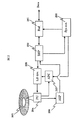
図2は一般的なディスク装置の構成の一部を示すものである。本発明は、記録方法に関わるものであるため、従来のディスク装置の構成をもって、その制御方法を工夫することにより実現される。従って、ディスク装置全体に関する構成の説明は省略し、本実施例に関わる部位のみを用いて、本実施例の実現手段について説明する。
【0022】
図2において、201はデータバッファである。ディスク装置に入力されるデータをディスクに記録するまでの間、一時的に蓄積する役割を果たす。また、ディスクから再生されたデータをディスク装置に繋がれたホスト装置に送るとき、一時的に蓄積する役割を果たす。なお、データバッファ201は複数のメモリによって構成されており、データを入力する一方で、データの出力が可能な構成とする。202はディジタル信号処理手段(以下、DSPと呼ぶ)である。データバッファ201から転送されたデータにエラー訂正付加し、実際にディスク記録するためのデータ形式にエンコードする役割を果たす。また、ディスクから再生された信号をデコードし、エラー訂正を行い、同時に再生データのエラーレートを算出する。さらにはディスクからの再生信号をもとにディスク上のアドレスを検出する。203はレーザードライバである。DSP202から転送されるデータに基づき、レーザーを駆動し、発光させる役割を果たす。204は光ピックアップである。内部にはレーザーを搭載しており、光ディスクに対し記録レーザー光、再生レーザー光を照射する。また、ディスクからの反射光を検出し、電気信号に変換する。さらには、レーザーの出射光の一部を取り出し、レーザーの発光パワーを監視するためのモニタ信号を出力する。205はデータを記録するための光ディスクである。206はアナログ信号処理手段(以下、ASPと呼ぶ)である。光ピックアップからの再生信号の振幅、位相等を調整し、二値化する役割を果たす。207は自動レーザーパワー調整手段(以下、APCと呼ぶ)である。光ピックアップ204から出力されるレーザーの発光パワーモニタ信号を監視し、設定された目標発光パワーになるようレーザードライバを随時制御する役割を果たす。208はディスク装置内の各部位を管理制御するシステムコントローラである。
【0023】
本実施例に関するシステムコントローラ208の役割は、
・データバッファ201に蓄積される記録データの蓄積量を監視し、適宜、ディスク205への記録を行わせる。
・ディスク装置内の各部位の機能停止・機能起動、または、各部位の電源オフ・電源オンを制御し、各部位の消費電力を制御する。
・直近に記録したデータの再生を行わせ、再生されデータに基づくエラーレートをDSP202に算出させる。
・前記エラーレートに基づき、APC207に追従させるレーザーの記録パワー目標値を設定する。である。
【0024】
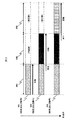
次に、図3を例に挙げ、図2に示すディスク装置によって本発明の記録方法を実現するための各部位の動作を説明する。図3は図1に示す分割データ102 A、B、Cを断続動作によってそれぞれ、ディスク205上の連続する領域 304、領域305、領域306に順次記録する様子を表す。なお、領域304に記録を行う際のレーザーの記録パワーにつていは、従来のディスク装置と同様、事前にディスク上の試し書き領域において種々の記録パワーにてテストパターンの記録を行い、そのテストパターンを再生することによって適したパワーに調整されているもとする。また、ディスクに記録するデータはディスク装置に接続されたホスト装置より入力されるものとする。
【0025】
まず、ディスク装置に対しホスト装置より記録すべき一連のデータが転送される。データバッファ201に規定量のデータが蓄積されるとシステムコントローラ208はこれを分割データ102−Aとし、システムコントローラ208は分割データ102−Aの記録を行うべく、データバッファに蓄積された分割データ102−AをDSP202に送り、同時にディスク205上の領域304の先頭前方に光ピックアップ204を位置付ける(光ピックアップ204の送り機構は図示せず)。なお、データバッファ201からDSP202へのデータ転送速度は、ホスト装置からデータバッファ201へのデータ転送速度を十分に上回る必要があり、本例では、その条件を満たしているものとする。以下はDSP202によって光ピックアップ204の位置(アドレス)が逐次検出され、ディスク205上の領域304の先頭に光ピックアップ204が達したところで、DSP202から出力される記録用データに基づきレーザードライバ203が光ピックアップ204を駆動し、分割データ102−Aがディスク205上の領域304に記録される。
【0026】
ディスク205上の領域304に分割データ102−Aが記録されたところでシステムコントローラ208は、ホスト装置からのデータを受け取る役割にあるデータバッファ201を除く記録時または再生時にさえ稼動していればよい各部位の機能を停止、または、電源をオフする。これにより記録断続期間が生成される。以上によって図3に示す301の記録状態となる。
【0027】
記録断続期間中にもデータバッファ201にはホスト装置からのデータが蓄積される。そして再びデータが規定量に達したところでシステムコントローラ208はこれを分割データ102−Bとする。これを記録すべく分割データ102−BをDSP202に転送する。同時に光ディスク205上の領域305の先頭より前方、すなわち領域304の終端付近に光ピックアップ204を位置付ける。そして、システムコントローラ208は領域304の終端付近から領域305の先頭までの領域において前回の記録した分割データ102−Aの一部を再生し、エラーレートをDSP202に算出させるとともに、そのエラーレートが規定の範囲内にあるか否かを判定する。エラーレートが規定範囲外にある場合はその数値に応じてAPC207に追従させるレーザーの目標記録パワー値を更新する。
【0028】
その後、光ピックアップ204が光ディスク205上の領域305の先頭に達したところで実際に分割データ102−Bが光ディスク205上の領域305に記録される。以上によって図3に示す302の記録状態となる。
【0029】
ディスク205上の領域305に分割データ102−Bが記録されたところでシステムコントローラ208は、ホスト装置からのデータを受け取るデータバッファ201を除く記録時または再生時にさえ稼動していればよい各部位の機能を停止、または、電源をオフする。これにより再び記録断続期間が生成される。
【0030】
引き続き記録断続期間中にもデータバッファ201にはホスト装置からのデータが蓄積される。そして再びデータが規定量に達したところでシステムコントローラ208はこれを分割データ102−Cとする。これを記録すべく分割データ102−CをDSP202に転送する。同時に光ディスク205上の領域306の先頭より前方、すなわち領域305の終端付近に光ピックアップ204を位置付ける。そして、システムコントローラ208は領域305の終端付近から領域306の先頭までの領域において前回の記録した分割データ102−Bの一部を再生し、エラーレートをDSP202に算出させるとともに、そのエラーレートが規定の範囲内にあるか否かを判定する。エラーレートが規定範囲外にある場合はその数値に応じてAPC207に追従させるレーザーの目標記録パワー値を更新する。
【0031】
その後、光ピックアップ204が光ディスク205上の領域306の先頭に達したところで実際に分割データ102−Cが光ディスク205上の領域306に記録される。以上によって図3に示す303の記録状態となる。
【0032】
ディスク205上の領域306に分割データ102−Cが記録されたところでシステムコントローラ208は、ホスト装置からのデータを受け取る役割にあるデータバッファ201を除く記録時または再生時にさえ稼動していればよい各部位の機能を停止、または、電源をオフする。これにより再び記録断続期間が生成される。
【0033】
図3では、各分割データの記録前に直近に記録されたデータの記録品質評価を行ったが、図4に示すように各分割データの記録直後に、記録を終えたばかりのデータの一部を再生し、記録品質を評価しても良い。ただし、図4に示す手順でも記録品質を評価できるものの、記録終了後に光ピックアップを記録データの再生ために移動させる操作が必要となる。一方、図3に示す各分割データの記録直前に記録品質の評価を行う方が、これは記録開始位置に光ピックアップを位置付ける操作を兼ねることが出来るので処理効率がよい。また、図3及び図4に示す両記録方法とも、過去(断続期間分)に記録されたデータの記録品質を新たな記録ための記録条件に反映させる。このため断続期間に急激な温度変化が起こる可能性を考慮する必要がある場合は、温度センサー等によって温度を監視、温度条件によって過去に記録したデータの記録品質を新たな記録の記録条件に反映させるか否かを決定するとよい。
【0034】
以上、図2に示すディスク装置による断続動作によって図1に示す分割データ102 A、B、Cをそれぞれ、図3及び図4に示す領域 304、領域305、領域306に順次記録する手順を説明したが、図1に示す分割データ102−D以降のデータについても同様に、上記の動作を繰り返すことによって記録される。そして、その記録されるデータは、分割データ単位の記録ごとにレーザーの記録パワーが適するよう調整する機会が設けられるため、より良好な記録品質が保たれる。また、記録品質の評価に用いるデータは、記録をしようとする領域の近傍であることからディスク面上の記録感度バラツキに対して的確に対応することが出来る。
【0035】
さらには、断続期間が設けられ、その期間においてディスク装置内の各部位の電力制御が可能なことから、ディスク装置内の温度上昇を抑制することができる。これにより、記録が長時間に亘っても良好な温度特性のもとレーザーを使用することが出来、記録すべきデータ全体に亘って良好な記録品質を保つことが出来る。
【0036】
なお、上記の説明では分割データを記録するたびにレーザーの記録パワーを調整するとしたが、測定誤差を回避するために複数回分の記録品質測定結果をまとめて評価し、複数回に一度の分割データ記録の際に、レーザーパワー調整の記録を行っても良い。また、ディスク装置内に温度センサが具備されており、レーザー近傍の温度が測定できる場合は、レーザーの記録パワーを調整する機会に前回の調整時からの温度変化幅を合わせ見て、記録パワーの調整を行うのもよい。
【0037】
【発明の効果】
記録品質の評価を行うとともに、その評価結果をレーザーの出力に反映させることによってデータ全体に亘って良好な記録品質を維持することができる。さらに、ディスク装置内部の温度上昇を抑え、これによってレーザーを記録が長時間に亘っても良好な温度特性のもと使用することもできる。
【図面の簡単な説明】
【図1】本発明の1実施例の断続記録動作時の断続期間を利用した記録データ評価手順を示す図。
【図2】本発明の1実施例におけるディスク装置の構成図。
【図3】本発明の1実施例におけるディスク装置の動作手順を説明するためのディスクへの記録方法を示す図。
【図4】本発明の1実施例におけるディスク装置の動作手順を説明するためのディスクへの記録方法を示す別の図。
【符号の説明】
101・・・記録データ、102・・・分割記録データ、
103・・・記録動作タイミング、104・・・記録品質評価タイミング
105・・・従来装置記録タイミング、
201・・・データバッファ、202・・・ディジタル信号処理手段、
203・・・レーザードライバ、204・・・光ピックアップ、
205・・・光ディスク、206・・・アナログ信号処理手段、
207・・・自動レーザーパワー調整手段、208・・・システムコントローラ、[0001]
BACKGROUND OF THE INVENTION
The present invention relates to an optical disc apparatus, and provides a technique for solving a problem that occurs when a series of data is continuously recorded.
[0002]
[Prior art]
In a conventional optical disc apparatus, recording is performed according to a recording method defined in a standard. However, in the recording method according to the standard, there may be a problem depending on the type of disk, the configuration of the apparatus, or the data recorded on the disk. The problem will be described below.
[0003]
In general, the sensitivity of the disc to laser light is not uniform over the entire disc surface. Further, the laser has a characteristic that its output changes due to the influence of the ambient temperature due to the heat generated by itself or the heat generated from the circuit in the apparatus. Therefore, it is necessary to evaluate the recording quality of data recorded at an appropriate time during recording and reflect the result on the output of the laser. Based on this, the recording method called Disc at Once defined in the standard and its problems will be explained.
[0004]
This Disc at Once recording method is a recording method used when recording data such as video and audio on a DVD-R, for example, when the recorded data realizes reproduction compatibility in a DVD video player. In this recording method, it is stipulated that data is continuously recorded from the inner periphery to the outer periphery of the disk without interruption. Therefore, in this recording method, it is necessary to continue recording without evaluating the sufficient recording quality of the recorded data until all the data is recorded. The reason that the recorded data cannot be sufficiently evaluated is that the recording head and the reproducing head are usually integrated in the optical disc apparatus. The most reliable method for evaluating the recording quality is to play back the recorded data. However, with a head that uses both recording and playback, playback cannot be performed unless recording is stopped. Therefore, in the conventional optical disc apparatus, since recording cannot be interrupted by the recording method such as Disc at Once, the recording quality cannot be reliably evaluated. It was difficult to keep. In particular, when the size of a series of data to be recorded is large and recording takes a long time, the temperature inside the disk device becomes very high, so the laser cannot be used with good temperature characteristics. It is difficult to maintain the recording quality, and it is more difficult to maintain the recording quality in a small disk device that has no room for installing a cooling means such as a fan.
[0005]
Some conventional apparatuses, for example, as disclosed in Japanese Patent Application Laid-Open No. 2001-34947, execute recording while performing adjustment so as to obtain optimum recording conditions while performing recording quality evaluation. However, in these cases, adjustment is made between recordings in consideration of a period during which data is not transferred from the host device connected to the disk device. However, when data is constantly transferred from the host device as in Disc at Once recording, recording must be continued constantly, and during that time, recording is performed under good recording conditions after sufficiently confirming the recording quality. It was difficult. For this reason, the recording quality is poor depending on the location on the disc, and recording may have to be performed again. This is particularly a problem when recording real-time data such as video and audio. When recording real-time data, the data itself being recorded is the original source. That is, the recording quality is evaluated after all the data has been recorded, and if the recording quality is poor, the recording cannot be performed again from the beginning. For this reason, the conventional apparatus cannot sufficiently cope with real-time recording. Also, even in the case of non-real-time recording where recording can be re-executed, a new disc is prepared for media that can be recorded only once, such as DVD-R. It was necessary to generate unnecessary costs.
[0006]
As described above, in the conventional disk device, particularly when a series of data such as Disc at Once recording has to be continuously recorded, the recording quality of the entire recorded data is maintained well. It was difficult. In addition, for this reason, a recording method in which a series of data such as Disc at Once recording must be continuously recorded in real-time recording such as video and audio as the original source immediately after the data being recorded is itself. In particular, it was difficult to record real-time data on a disc that can be recorded only once, such as DVD-R.
[0007]
[Problems to be solved by the invention]
An object of the present invention is to solve the problems that occur when recording a series of data that is determined to be continuously recorded, such as Disc at Once recording, in a conventional disk device. The problem was that a series of data was recorded continuously, so the quality of the data recorded during recording could not be evaluated and the laser output could not be controlled properly. The recording quality deteriorates due to the fluctuation. In addition, the laser can be used with good temperature characteristics for a long time because the temperature inside the disk device reaches a high temperature due to the heat generated from the circuit inside the disk device for continuous recording. It was a point that was not possible.
[0008]
Furthermore, it is a problem to be solved by the present invention to realize real-time data recording and recording on a disk medium that can be recorded only once with good recording quality by solving the above problems.
[0009]
Of course, even in the recording method of the conventional disk device, before recording, a test pattern is recorded with various laser powers in the test writing area on the disk, and an appropriate output value of the laser is obtained based on the reproduction result of the test pattern. I was asking. Therefore, when the series of data to be recorded is not so large, there is almost no problem even if the laser output cannot be sufficiently adjusted during recording. However, if the series of data to be recorded is large and must be recorded over a long period of time, the recording cannot be adjusted sufficiently during the recording. Can not cope with. Further, when recording is performed for a long time, the temperature inside the disk device becomes very high, so that the laser cannot be used with good temperature characteristics, and the recording quality is liable to be deteriorated. Although there is a method of providing a cooling means such as a fan so as not to raise the temperature in the disk device, there is a problem that the cost increases. Moreover, it is very difficult to provide a cooling means such as a fan in a portable small disk device due to space limitations and power source limitations, and the high temperature inside the device is a particular problem.
[0010]
[Means for Solving the Problems]
In order to solve the above problems, in the present invention, On optical disc Real thai Mude In an optical disk device for recording data, an optical disk device In the data buffer Entered Real time Divide the data, and split the data at a speed that exceeds the data input speed to the optical disk device. On optical disc Recording is performed, and as a result, the recorded data is controlled to be reproduced in the same manner as in the case of continuous recording. And During the period when data is input to the optical disc device in real time, Until the next segmented data is recorded To disk The recording quality of the reproduced data is evaluated by reproducing the data recorded on the optical disk before recording each divided data by using the period in which the recording is interrupted, and the evaluation result is evaluated by the laser. In this way, control is performed so that the recording quality is maintained well over the entire data. Further, during the period in which the recording until the next divided data is recorded is stopped, the function of each part in the disk device is stopped or the power is turned off to suppress the temperature rise inside the disk device. Thus, the laser output change is reduced, and control is performed so that good recording quality is maintained even during long-time recording. Furthermore, a series of data, which is data to be recorded continuously according to the standard, is intentionally divided, and recording is intermittently performed in the divided units.
[0011]
DETAILED DESCRIPTION OF THE INVENTION
FIG. 1 shows an embodiment of a method for recording data on an optical disk according to the present invention.
[0012]
In FIG. 1, reference numeral 101 denotes a series of recording data to be recorded continuously according to the standard. For comparison,
[0013]
On the other hand, in this embodiment, as shown at 102, the recording data 101 is divided and managed in a certain recording unit. For example, in the case of DVD-R, recording is performed by dividing the unit into an integral multiple of ECC block units. In FIG. 1, as an example, there are 10 divisions from A to J. The divided recording data 102 from A to J is divided and recorded intermittently at 103 at the timing. The recording period of each divided data is shorter than the width of each divided data. The recording data input to the disk device is temporarily stored in the data buffer and then input to the data buffer of the device. This is because data is taken out from the data buffer and recorded at a speed exceeding the data input speed. By performing the intermittent recording shown in 103, a recording intermittent period can be provided between the recording of each divided data.
[0014]
Further, the function of each part in the disk device can be stopped during the recording intermittent period. As a result, the power consumption of the entire disk device can be suppressed, the temperature increase inside the disk device can be moderated and the temperature increase can be suppressed, and the laser can be used with good temperature characteristics for a long time.
[0015]
However, a series of data is not continuously recorded in accordance with the standard, and there is a problem that a connection is made because connection recording is performed for each division unit.
[0016]
However, with regard to this, with the link recording technology generally used in disk devices at present, recorded data and data adjacent thereto can be connected and recorded with an error of several bytes. Further, the error due to splice recording is within a range that can be sufficiently corrected by the error correction code recorded at the same time when data is recorded. Therefore, the recorded data can be reproduced in the same manner as when recording is continuously performed, and there is no problem.
[0017]
As described above, the recording method of the present embodiment reproduces recorded data in the same manner as in the case of continuous recording performed in a conventional disk device, although recording seams occur. In addition, since the laser output can be adjusted so that the recorded data has periodically suitable recording conditions, the recording quality is good over the entire series of data to be recorded. Furthermore, since the temperature rise inside the disk unit can be suppressed by stopping the function of each part during the intermittent recording operation by the intermittent recording operation, the laser is used under good temperature characteristics even for long-time recording. And good recording quality can be maintained.
[0018]
Therefore, the recording method and apparatus of this embodiment are suitable for a low-priced disk device and a portable small-sized disk device to which a cooling means such as a fan cannot be attached. In addition, the recording time often takes a long time, and real-time recording such as video and audio that cannot be re-recorded can be performed under stable recording conditions, which is useful. In addition, even in the case of non-real-time recording, write quality such as DVD-R that can be recorded only once because good recording quality is maintained even if recording is performed for a long time. It is also suitable for recording on a medium.
[0019]
Note that, according to the standard, a series of data to be recorded continuously refers to data in a recording method such as Disc at once. Therefore, for example, the same applies when Disc at once recording is applied even to a rewritable medium such as a DVD-RW. In Disc at once recording, which is a series of data that should be recorded continuously on any medium, a series of data is intentionally divided and recorded. This is the same as the case of continuous recording. The reason for dividing and recording a series of data is to adjust the recording power during the intermittent recording period and maintain good recording quality over the entire surface of the optical disc.
[0020]
Further, the advantage of the recording method of this embodiment is that the recording quality is evaluated in the vicinity of the area where recording is actually performed. This is suitable for dealing with variations in recording sensitivity on the disk surface. Further, the recording quality is evaluated based on the actually recorded data without recording the test pattern when evaluating the recording quality. Therefore, it is not necessary to move the recording head to the test writing area every time the recording quality is evaluated, and it is not necessary to record the test pattern, so that the recording quality can be evaluated in a very short time. Further, by reproducing the data recorded immediately before the recording of each divided data, the head is positioned at the recording start position, and the processing can be performed efficiently. As an actual recording quality evaluation method, an error rate, jitter, asymmetry, and the like of reproduction data generally used in a conventional disk device may be measured.
[0021]
FIG. 2 shows means for realizing the recording method of the present embodiment shown in FIG.
FIG. 2 shows a part of the configuration of a general disk device. Since the present invention relates to a recording method, it is realized by devising the control method with the configuration of a conventional disk device. Therefore, the description of the configuration relating to the entire disk device is omitted, and the means for realizing this embodiment will be described using only the parts related to this embodiment.
[0022]
In FIG. 2, 201 is a data buffer. It plays a role of temporarily storing data input to the disk device until it is recorded on the disk. Also, when data reproduced from the disc is sent to a host device connected to the disc device, it plays a role of temporarily storing it. Note that the
[0023]
The role of the
The amount of recording data stored in the
Controls the function stop / function start of each part in the disk device or the power-off / power-on of each part to control the power consumption of each part.
-The most recently recorded data is reproduced, and the
Based on the error rate, a laser recording power target value to be followed by the
[0024]
Next, taking FIG. 3 as an example, the operation of each part for realizing the recording method of the present invention by the disk device shown in FIG. 2 will be described. FIG. 3 shows a state in which the divided data 102 A, B, and C shown in FIG. 1 are sequentially recorded in the
[0025]
First, a series of data to be recorded is transferred from the host device to the disk device. When a predetermined amount of data is accumulated in the
[0026]
When the divided data 102-A is recorded in the
[0027]
Data from the host device is accumulated in the
[0028]
Thereafter, when the
[0029]
When the divided data 102-B is recorded in the
[0030]
Subsequently, data from the host device is accumulated in the
[0031]
Thereafter, when the
[0032]
When the divided data 102-C is recorded in the
[0033]
In FIG. 3, the recording quality of the data recorded most recently before the recording of each divided data was evaluated. As shown in FIG. 4, immediately after the recording of each divided data, a part of the data that has just been recorded is recorded. It is possible to reproduce and evaluate the recording quality. However, although the recording quality can be evaluated by the procedure shown in FIG. 4, an operation for moving the optical pickup to reproduce the recorded data is necessary after the recording is completed. On the other hand, if the recording quality is evaluated immediately before the recording of each divided data shown in FIG. 3, the processing efficiency is better because this can also serve as an operation of positioning the optical pickup at the recording start position. In both the recording methods shown in FIGS. 3 and 4, the recording quality of data recorded in the past (for the intermittent period) is reflected in the recording conditions for new recording. For this reason, when it is necessary to consider the possibility of sudden temperature changes during the intermittent period, the temperature is monitored by a temperature sensor, etc., and the recording quality of the data recorded in the past according to the temperature conditions is reflected in the new recording conditions. It is better to decide whether or not to do so.
[0034]
The procedure for sequentially recording the divided data 102 A, B, and C shown in FIG. 1 in the
[0035]
Furthermore, since an intermittent period is provided and power control of each part in the disk device is possible during that period, a temperature rise in the disk device can be suppressed. As a result, the laser can be used under good temperature characteristics even for a long time of recording, and good recording quality can be maintained over the entire data to be recorded.
[0036]
In the above description, the recording power of the laser is adjusted every time divided data is recorded. However, in order to avoid measurement errors, the recording quality measurement results for a plurality of times are collectively evaluated, and the divided data is obtained once every plurality of times. During recording, laser power adjustment recording may be performed. In addition, if a temperature sensor is provided in the disk unit and the temperature in the vicinity of the laser can be measured, the temperature of the recording power can be adjusted by checking the width of temperature change from the previous adjustment on the occasion of adjusting the laser recording power. Adjustments may be made.
[0037]
【The invention's effect】
Record By evaluating the recording quality and reflecting the evaluation results in the laser output. De Good recording quality can be maintained over the entire data. further , De Use the laser with good temperature characteristics even when recording for a long time by suppressing the temperature rise inside the disk device. Also it can.
[Brief description of the drawings]
FIG. 1 is a diagram illustrating a recording data evaluation procedure using an intermittent period during an intermittent recording operation according to an embodiment of the present invention.
FIG. 2 is a configuration diagram of a disk device according to an embodiment of the present invention.
FIG. 3 is a diagram showing a recording method on a disk for explaining an operation procedure of the disk device in one embodiment of the present invention.
FIG. 4 is another diagram showing a recording method on a disk for explaining an operation procedure of the disk device in one embodiment of the present invention.
[Explanation of symbols]
101 ... recording data, 102 ... divided recording data,
103 ... Recording operation timing, 104 ... Recording quality evaluation timing
105 ... Conventional device recording timing,
201 ... data buffer, 202 ... digital signal processing means,
203 ... Laser driver, 204 ... Optical pickup,
205 ... Optical disc, 206 ... Analog signal processing means,
207 ... Automatic laser power adjustment means, 208 ... System controller,
Claims (15)
光ディスク装置のデータバッファに入力されたリアルタイムデータを分割する工程と、
分割されたデータを光ディスク装置へのデータ入力速度を上回る速度で光ディスクに記録する工程と、
光ディスク装置にリアルタイムにデータが入力されている期間中で、次に分割されたデータを記録するまでの前記記録工程が中断されている期間に、
光ディスクに既に記録されたデータを再生する工程と、
前記再生されたデータの再生信号に基づきデータの記録状態を評価する工程と、前記再生されたデータの評価に基づき、次に分割されたデータを記録するレーザーの記録パワーを調整する工程とからなり、
上記記録、再生、評価、レーザーの記録パワーを調整する工程を繰り返すことによってリアルタイムデータを記録する光ディスク記録方法。An optical disk Symbol recording method in the optical disc apparatus you record the real-time data on the optical disk,
Dividing the real-time data input to the data buffer of the optical disc device;
And recording on an optical disk the divided data at a rate greater than the data input speed to the optical disk apparatus,
During periods of real-time data is input to an optical disk device, then divided data in the period in which the recording process until the recording is interrupted,
Reproducing the data already recorded on the optical disc;
A step of evaluating the data recording state on the basis of the reproduced signal of the reproduced data on the basis of the evaluation of the reproduced data, then consists of a step of adjusting the recording power of the laser for recording the divided data ,
An optical disk recording method for recording real-time data by repeating the steps of recording, reproduction, evaluation, and adjustment of laser recording power.
レーザーを良好な温度特性のもと使用できるよう制御する
ことを特徴とする光ディスク記録方法。In claim 5, when the temperature rise of the disk device becomes gradual,
An optical disk recording method comprising controlling a laser so that it can be used under good temperature characteristics.
光ディスク装置のデータバッファに入力されたリアルタイムデータを分割する手段と、
分割されたデータを光ディスク装置へのデータ入力速度を上回る速度で光ディスクに記録する手段と、
光ディスク装置にリアルタイムにデータが入力されている期間中で、次に分割されたデータを記録するまでの前記記録手段の記録が中断されている期間に、
光ディスクに既に記録されたデータを再生する手段と、
前記再生されたデータの再生信号に基づきデータの記録状態を評価する手段、
前記再生されたデータの評価に基づき、次に分割されたデータを記録するためのレーザーの記録パワーを調整する手段とを有し、
上記データの記録、データの再生、およびデータの再生結果に基づくレーザーの記録パワーの調整を繰り返し行なうことを特徴とする光ディスク装置。There is provided an optical disk apparatus for recording the real Thailand Mude over data on the optical disk,
Means for dividing real-time data input to the data buffer of the optical disc device;
Means for recording the divided data on the optical disc at a speed exceeding the data input speed to the optical disc apparatus;
During the period in which data is input in real time to the optical disc apparatus, during the period in which the recording of the recording means is interrupted until the next divided data is recorded,
Means for reproducing data already recorded on the optical disc;
Means for evaluating the recorded state of data on the basis of the reproduced signal of the reproduced data,
Based on the evaluation of the reproduced data, have a means for adjusting the recording power of the laser for recording next divided data,
An optical disc apparatus characterized by repeatedly performing the data recording, data reproduction, and laser recording power adjustment based on the data reproduction result .
ことを特徴とする光ディスク装置。8. The optical disk apparatus according to claim 7, wherein the data reproduced during the recording interruption period is data recorded in the vicinity of a position where the next divided data is to be recorded.
光ディスクが一回のみ書き込みが可能な媒体である
ことを特徴とする光ディスク装置。In claim 7,
An optical disc apparatus, wherein the optical disc is a medium that can be written only once.
光ディスクに記録するデータが映像と音声、または、そのどちらか一方である
ことを特徴とする光ディスク装置。In claim 7,
An optical disc apparatus characterized in that data to be recorded on an optical disc is video and / or audio.
温度変化幅に応じて、前記再生されたデータに基づくレーザー記録パワーの調整を行なうか否かを前記調整手段にて判断する
ことを特徴とする光ディスク装置。In Claim 7, it has a means to monitor the temperature of a disk unit,
An optical disc apparatus, wherein the adjusting means determines whether or not to adjust the laser recording power based on the reproduced data according to a temperature change width.
ことを特徴とする光ディスク装置。8. The optical disc apparatus according to claim 7, wherein the data is a series of data to be continuously recorded in accordance with a standard for recording on an optical disc, and is intentionally divided and recorded.
ディスク装置の各部位の機能を停止する、または、電源を切る
ことを特徴とする光ディスク装置。In claim 7, in a period in which recording in intermittent recording processing is not performed,
An optical disc device characterized in that the function of each part of the disc device is stopped or the power is turned off.
Priority Applications (3)
| Application Number | Priority Date | Filing Date | Title |
|---|---|---|---|
| JP2001348166A JP3870759B2 (en) | 2001-11-14 | 2001-11-14 | Optical disc recording method and optical disc apparatus |
| US10/095,663 US6954411B2 (en) | 2001-11-14 | 2002-03-08 | Optical disc recording method and optical disc drive |
| US11/218,580 US7218586B2 (en) | 2001-11-14 | 2005-09-02 | Intermittent optical disc recording method and optical disc drive splitting data |
Applications Claiming Priority (1)
| Application Number | Priority Date | Filing Date | Title |
|---|---|---|---|
| JP2001348166A JP3870759B2 (en) | 2001-11-14 | 2001-11-14 | Optical disc recording method and optical disc apparatus |
Related Child Applications (1)
| Application Number | Title | Priority Date | Filing Date |
|---|---|---|---|
| JP2005315621A Division JP3901204B2 (en) | 2005-10-31 | 2005-10-31 | Optical disc recording method and optical disc apparatus |
Publications (3)
| Publication Number | Publication Date |
|---|---|
| JP2003151134A JP2003151134A (en) | 2003-05-23 |
| JP2003151134A5 JP2003151134A5 (en) | 2004-08-12 |
| JP3870759B2 true JP3870759B2 (en) | 2007-01-24 |
Family
ID=19161036
Family Applications (1)
| Application Number | Title | Priority Date | Filing Date |
|---|---|---|---|
| JP2001348166A Expired - Fee Related JP3870759B2 (en) | 2001-11-14 | 2001-11-14 | Optical disc recording method and optical disc apparatus |
Country Status (2)
| Country | Link |
|---|---|
| US (2) | US6954411B2 (en) |
| JP (1) | JP3870759B2 (en) |
Families Citing this family (6)
| Publication number | Priority date | Publication date | Assignee | Title |
|---|---|---|---|---|
| JP3863497B2 (en) * | 2002-12-04 | 2006-12-27 | 株式会社リコー | Optical information recording apparatus and optical information processing apparatus |
| JP4890736B2 (en) * | 2003-06-16 | 2012-03-07 | 三星電子株式会社 | Optical disc apparatus and laser output control method |
| US7630302B2 (en) * | 2003-12-23 | 2009-12-08 | At&T Intellectual Property I, L.P. | Method and system for providing a failover circuit for rerouting logical circuit data in a data network |
| WO2005109418A1 (en) * | 2004-05-12 | 2005-11-17 | Koninklijke Philips Electronics N.V. | Optimal power control |
| US20080151725A1 (en) * | 2005-01-12 | 2008-06-26 | Koninklijke Philips Electronics, N.V. | Apparatus And Method For Optimized Write Strategy Control |
| JP5397412B2 (en) | 2011-05-20 | 2014-01-22 | 船井電機株式会社 | Optical disc recording apparatus and optical disc recording method |
Family Cites Families (16)
| Publication number | Priority date | Publication date | Assignee | Title |
|---|---|---|---|---|
| EP0213623B1 (en) * | 1985-09-02 | 1996-01-10 | Sharp Kabushiki Kaisha | Optical disc recording and reproducing apparatus |
| DE3888565T2 (en) * | 1987-04-28 | 1994-10-20 | Sharp Kk | Recording and playback device. |
| JP2653259B2 (en) * | 1991-03-19 | 1997-09-17 | 松下電器産業株式会社 | Recording laser intensity setting method and laser recording apparatus |
| JP3227756B2 (en) * | 1992-01-24 | 2001-11-12 | ソニー株式会社 | Disk recording device, disk reproducing device, and disk recording / reproducing device |
| JPH06119758A (en) * | 1992-10-05 | 1994-04-28 | Yamaha Corp | Disk recording and reproducing device |
| JPH07244930A (en) | 1994-03-03 | 1995-09-19 | Sony Corp | Optical disk device |
| US5841598A (en) * | 1994-10-28 | 1998-11-24 | Olympus Optical Co., Ltd. | Information recording/reproducing apparatus and data processing method |
| US6052347A (en) * | 1996-02-23 | 2000-04-18 | Ricoh Company, Ltd. | Method and apparatus for detecting optimum recording power for an optical disk |
| JPH09282665A (en) | 1996-04-12 | 1997-10-31 | Ricoh Co Ltd | Information recording device and information recording medium |
| JP4110593B2 (en) * | 1997-05-19 | 2008-07-02 | ソニー株式会社 | Signal recording method and signal recording apparatus |
| TW399181B (en) * | 1997-09-17 | 2000-07-21 | Matsushita Electric Ind Co Ltd | Video data editing apparatus and computer-readable recording medium storing an editing program |
| JP2000182245A (en) | 1998-12-14 | 2000-06-30 | Victor Co Of Japan Ltd | Device and method for recording and reproduction of optical disk |
| JP2001034947A (en) | 1999-07-23 | 2001-02-09 | Sony Corp | Disk driver and method of determining execution timing of adjusting operation |
| JP2001160265A (en) | 1999-11-30 | 2001-06-12 | Ricoh Co Ltd | Voice information recording and reproducing device |
| JP2001283439A (en) * | 2000-03-31 | 2001-10-12 | Sanyo Electric Co Ltd | Method for setting light emitting output of optical head in optical disk recorder |
| JP3768089B2 (en) * | 2000-11-15 | 2006-04-19 | 三洋電機株式会社 | Laser output setting method for optical disc recording / reproducing apparatus |
-
2001
- 2001-11-14 JP JP2001348166A patent/JP3870759B2/en not_active Expired - Fee Related
-
2002
- 2002-03-08 US US10/095,663 patent/US6954411B2/en not_active Expired - Lifetime
-
2005
- 2005-09-02 US US11/218,580 patent/US7218586B2/en not_active Expired - Fee Related
Also Published As
| Publication number | Publication date |
|---|---|
| US20030090973A1 (en) | 2003-05-15 |
| JP2003151134A (en) | 2003-05-23 |
| US6954411B2 (en) | 2005-10-11 |
| US7218586B2 (en) | 2007-05-15 |
| US20060007823A1 (en) | 2006-01-12 |
Similar Documents
| Publication | Publication Date | Title |
|---|---|---|
| KR20080013805A (en) | Electronic device, control method, and control program | |
| JP2006503395A (en) | Optical disk device | |
| KR20030020965A (en) | Information recording medium, information recording and reproduction method, and information recording and reproduction apparatus | |
| US7218586B2 (en) | Intermittent optical disc recording method and optical disc drive splitting data | |
| US7366073B2 (en) | Information recording apparatus and method, and computer program product | |
| JP4114330B2 (en) | Optical disc device and information storage device using the same | |
| JP3901204B2 (en) | Optical disc recording method and optical disc apparatus | |
| JP2007172770A (en) | Optical disk drive | |
| US20070076551A1 (en) | Data write method and optical disc apparatus | |
| US7023771B2 (en) | Optical information recording apparatus | |
| US20070047409A1 (en) | Data recording system and control method thereof | |
| KR100998910B1 (en) | Method and apparatus for determining an optimum laser power | |
| JP3802368B2 (en) | Disc recording / playback device | |
| KR100696839B1 (en) | Recording method for optical recorder | |
| KR100615697B1 (en) | Method for determining driving level of beam-source in optical disk reproducing device in use of interpolation | |
| SG160214A1 (en) | Method of recording and/or reproducing temporary defect list, recording and/or reproducing apparatus, and write-once recording medium | |
| US8018826B2 (en) | Recording device and method, and computer program | |
| JP3895587B2 (en) | Phase change optical disc formatting method and phase change optical disc formatted by the method | |
| JPH1116189A (en) | Optical disk device | |
| JP2008108371A (en) | Optical disk device | |
| JP2004318967A (en) | Information recording method and optical disk device | |
| KR20090081522A (en) | Recording medium, method and appratus for verificating recording medium | |
| JP2000311341A (en) | Optical information recording and reproducing device | |
| JP2003281720A (en) | Information recording device, program and recording medium | |
| JP2008130113A (en) | Optical disk device |
Legal Events
| Date | Code | Title | Description |
|---|---|---|---|
| A977 | Report on retrieval |
Free format text: JAPANESE INTERMEDIATE CODE: A971007 Effective date: 20050318 |
|
| A131 | Notification of reasons for refusal |
Free format text: JAPANESE INTERMEDIATE CODE: A131 Effective date: 20050830 |
|
| A521 | Written amendment |
Free format text: JAPANESE INTERMEDIATE CODE: A523 Effective date: 20051031 |
|
| A02 | Decision of refusal |
Free format text: JAPANESE INTERMEDIATE CODE: A02 Effective date: 20051129 |
|
| A521 | Written amendment |
Free format text: JAPANESE INTERMEDIATE CODE: A523 Effective date: 20060126 |
|
| A911 | Transfer to examiner for re-examination before appeal (zenchi) |
Free format text: JAPANESE INTERMEDIATE CODE: A911 Effective date: 20060215 |
|
| RD01 | Notification of change of attorney |
Free format text: JAPANESE INTERMEDIATE CODE: A7421 Effective date: 20060427 |
|
| TRDD | Decision of grant or rejection written | ||
| A01 | Written decision to grant a patent or to grant a registration (utility model) |
Free format text: JAPANESE INTERMEDIATE CODE: A01 Effective date: 20060926 |
|
| A61 | First payment of annual fees (during grant procedure) |
Free format text: JAPANESE INTERMEDIATE CODE: A61 Effective date: 20061009 |
|
| FPAY | Renewal fee payment (event date is renewal date of database) |
Free format text: PAYMENT UNTIL: 20091027 Year of fee payment: 3 |
|
| FPAY | Renewal fee payment (event date is renewal date of database) |
Free format text: PAYMENT UNTIL: 20101027 Year of fee payment: 4 |
|
| FPAY | Renewal fee payment (event date is renewal date of database) |
Free format text: PAYMENT UNTIL: 20111027 Year of fee payment: 5 |
|
| FPAY | Renewal fee payment (event date is renewal date of database) |
Free format text: PAYMENT UNTIL: 20121027 Year of fee payment: 6 |
|
| FPAY | Renewal fee payment (event date is renewal date of database) |
Free format text: PAYMENT UNTIL: 20121027 Year of fee payment: 6 |
|
| FPAY | Renewal fee payment (event date is renewal date of database) |
Free format text: PAYMENT UNTIL: 20131027 Year of fee payment: 7 |
|
| S111 | Request for change of ownership or part of ownership |
Free format text: JAPANESE INTERMEDIATE CODE: R313111 |
|
| LAPS | Cancellation because of no payment of annual fees |