JP3870171B2 - ENCODING METHOD, ENCODING DEVICE, COMPUTER PROGRAM, AND COMPUTER-READABLE STORAGE MEDIUM - Google Patents
ENCODING METHOD, ENCODING DEVICE, COMPUTER PROGRAM, AND COMPUTER-READABLE STORAGE MEDIUM Download PDFInfo
- Publication number
- JP3870171B2 JP3870171B2 JP2003064778A JP2003064778A JP3870171B2 JP 3870171 B2 JP3870171 B2 JP 3870171B2 JP 2003064778 A JP2003064778 A JP 2003064778A JP 2003064778 A JP2003064778 A JP 2003064778A JP 3870171 B2 JP3870171 B2 JP 3870171B2
- Authority
- JP
- Japan
- Prior art keywords
- data
- input
- continuous
- encoded
- value
- Prior art date
- Legal status (The legal status is an assumption and is not a legal conclusion. Google has not performed a legal analysis and makes no representation as to the accuracy of the status listed.)
- Expired - Fee Related
Links
Images


Classifications
-
- H—ELECTRICITY
- H04—ELECTRIC COMMUNICATION TECHNIQUE
- H04N—PICTORIAL COMMUNICATION, e.g. TELEVISION
- H04N19/00—Methods or arrangements for coding, decoding, compressing or decompressing digital video signals
- H04N19/90—Methods or arrangements for coding, decoding, compressing or decompressing digital video signals using coding techniques not provided for in groups H04N19/10-H04N19/85, e.g. fractals
- H04N19/93—Run-length coding
-
- H—ELECTRICITY
- H03—ELECTRONIC CIRCUITRY
- H03M—CODING; DECODING; CODE CONVERSION IN GENERAL
- H03M7/00—Conversion of a code where information is represented by a given sequence or number of digits to a code where the same, similar or subset of information is represented by a different sequence or number of digits
- H03M7/30—Compression; Expansion; Suppression of unnecessary data, e.g. redundancy reduction
- H03M7/46—Conversion to or from run-length codes, i.e. by representing the number of consecutive digits, or groups of digits, of the same kind by a code word and a digit indicative of that kind
Description
【0001】
【発明の属する技術分野】
本発明は符号化データを処理し、再符号化する技術に関するものである。
【0002】
【従来の技術】
データの圧縮符号化技術としてパックビッツ符号化が知られている。このパックビッツ符号化とはランレングス符号化の1つであり、符号化前の情報を損失することなし復号可能、すなわち、ロスレス符号化でもある。
【0003】
以下、パックビッツ符号化の説明を、符号化を行う単位であるひとつのデータが8ビットで構成されているものとして行う(データとしては例えば8ビット多値画素データである)。また、符号化する以前のデータを生データと呼び、符号化以前の生データのストリームを生データ列と呼ぶ。
【0004】
パックビッツ符号化とは、生データ列を、「同じデータが連続する部分」と「異なるデータが連続する部分」とに区別し、それぞれの部分に対してデータの「長さ情報」を付加するものである。そして、「同じデータが連続する部分」に関しては、「連続する数+データ」という形に、また「異なるデータが連続する部分」に関しては「異なるデータが連続する数+異なるデータ列」という形で表す。そしてこの処理で生成したデータ列をパックビッツ符号化データとして出力する。
【0005】
今、以下の(1)ような生データ列(24個のデータ)が入力されたとする。個々のデータは8ビット(0〜255の範囲のデータ)。
0,0,0,0,1,2,3,4,4,4,4,4,4,4,4,5,5,6,7,8,8,9,10,10 … (1)
この場合、生データ列を
0,0,0,0,
1,2,3,
4,4,4,4,4,4,4,4,
5,5,
6,7,
8,8,
9,
10,10 … (2)
というように、「同じデータが連続する部分」と、「異なるデータが連続する部分」とに区別する。そして、それぞれの部分に「長さ情報」を付加し、「同じデータが連続する部分」に関してはデータ部分を1つだけに圧縮する。
【0006】
0,0,0,0, ⇒ (-4),0,
1,2,3, ⇒ (3),1,2,3,
4,4,4,4,4,4,4,4, ⇒ (-8),4,
5,5, ⇒ (-2),5,
6,7, ⇒ (2),6,7,
8,8, ⇒ (-2),8,
9, ⇒ (1),9,
10,10 ⇒ (-2),10 … (3)
(3)では「長さ情報」は括弧で囲んで示している。「長さ情報」を正負の値で示したのは、連続する部分が同じデータであるのか、異なるデータであるのかを区別するためである。すなわち、負の数は「同じデータの連続部分」を表し、正の数は「異なるデータの連続部分」を表している。そして、この「長さ情報」をデータと同じく8ビットの幅を持つ「長さコードデータ」としてデータ列に埋め込んで出力する。すなわち、長さコードデータの8ビットの最上位ビットMSBを正負の符号ビットとして扱う。
【0007】
また、上記の値「9」のように1つだけ孤立して存在するデータについては、「異なるデータが1つある」と定義する。そのため、同じデータの連続する数は最低でも2つ以上となる。
【0008】
長さコードデータと、「同じ値のデータが連続する数」、及び、「異なる値のデータが連続する数」との関係(テーブル)は次のようになる(注:「0x」は16進数を示す)。
【0009】
異なるデータが連続する数 長さコードデータ
1 0x00
2 0x01
3 0x02
: :
127 0x7E
128 0x7F
同じデータが連続する数 長さコードデータ
2(−2) 0xFF
3(−3) 0xFE
: :
127(−127) 0x82
128(−128) 0x81
したがって、先に示した生データ列(1)をパックビッツ符号化すると、次の示す符号化データ列(4)が生成されることになる。
FD,00,02,01,02,03,F9,04,FF,5,01,06,07,FF,08,00,09,FF,10 … (4)
上記の如く、パックビッツ符号化では、同じデータの連続する数は2乃至128まで表現でき、異なるデータの連続する数は1乃至128まで表現できる。従って、仮に、同じデータが連続する数が129以上の場合には、128個まで連続する符号(長さコードデータ+連続するデータ)を生成し、129番目以降については、その129番目のデータを起点とする符号を生成することになる。これは異なるデータの連続する場合にも同様である。
【0010】
尚、上記表に示すようにパックビッツ符号化では「長さコードデータ」として0x80を生成しない。従って、この「0x80」を、符号化データ列の最後を表すエンドオブリストコードデータとして定義することもある。
【0011】
以降、パックビッツ符号化データにおいて「長さコードデータ」のことを「長さ情報」、長さ情報に続いて出力される実際のデータの値を示す部分を「データ部」という言葉で表現することとする。
【0012】
以上のように、パックビッツ符号化では同じ値のデータが連続して現れる回数が増加すると符号化後のデータ量が減少する(圧縮率が高くなる)。
【0013】
【発明が解決しようとする課題】
一般に、データを圧縮する場合、生データの量(サイズ)に対して、1/2以下(圧縮率2倍以上)とか、1/4以下(圧縮率4倍以上)といった目標を立てて圧縮符号化を行うことが多い。パックビッツ符号化の場合、同じデータが3つ以上連続する場合に圧縮率が向上することになるが、異なるデータが連続することが多い場合には「長さ情報」が付加される分だけデータ量が増えることになる。
【0014】
従って、パックビッツ符号化を行って目標とするデータ量に到達できない場合には、同じデータが連続するように変更を加えない限り、それを実現できない。 ここで、生データの或るビットを0に固定すると、取り得る値の種類数は半分と少なくなり、必然的に同じ値が連続する確率が高くなるので、このようなデータを圧縮した場合は高い圧縮率となる。例えば、圧縮符号化対象として多値画素を例にすると、LSBを0にした場合、2n、2n+1(nは0、1、2…)で表現される画素値は共に「2n」に丸められる。中間調画像の場合にはもともと隣接する画素の濃度や輝度はその差が小さいので、上記のようにビット値を変更することで更に同じ値になり易くなる。即ち、上記ビット変更処理を行えば、より高い圧縮率になることがわかるであろう。同様に、適当な2ビットを0にすると、更に高い圧縮率となるのは理解できよう。
【0015】
しかしながら、オリジナルとなる生データの集合(例えば多値画像データ)の1つ1つのデータに上記の丸め処理を行うには、そのデータ量に比例した処理が必要になり、高い処理速度は望めない。また、そのためにオリジナルの生データ全体を記憶しておくメモリも必要とする。
【0016】
そこで、本願発明は、パックビッツ符号化データの如く、同じデータの連続数を示す連続数コード部と前記データを示すデータ部、及び、異なるデータ列の連続数を示す連続数コード部と前記異なるデータ列を示すデータ部のデータ形式で表現される符号化データを、復号することなく、同じデータ形式に、より高い圧縮率で再符号化する技術を提供しようとするものである。
【0017】
【課題を解決するための手段】
かかる課題を解決するため、例えば本発明の符号化方法は以下の工程を備える。すなわち、
同じデータの連続数を示す連続数コード部と前記データを示すデータ部とで表される第1のタイプの符号化データ、又は、異なるデータの連続数を示す連続コード部と前記異なるデータのデータ部で表わされる第2のタイプの符号化データを順次入力し、前記第1又は第2のタイプの符号化データ形式の符号化データに再符号化する符号化方法であって、
入力した符号化データの連続数コード部に基づき、注目符号化データが前記第1、第2のタイプのいずれの符号化データであるかを判定する判定工程と、
該判定工程で注目符号化データが前記第1のタイプの符号化データであると判定した場合には、注目符号化データ中の連続数コード部で示される連続個数情報と、データ部で示されるデータを出力し、
該判定工程で注目符号化データが前記第2のタイプの符号化データであると判定した場合には、注目符号化データ中のデータ部の個々のデータを出力する際、同じデータの連続個数が“1”であることを示す連続個数情報を出力する符号化データ分離工程と、
前記符号化データ分離工程より出力された連続個数情報及びデータのうち、前記データの一部のビットを所定値に変更し、出力するデータ変更工程と、
前記符号化データ分離工程より出力された連続個数情報、及び、前記データ変更工程で処理されたデータとを入力し、復号処理することなく、前記第1又は第2のタイプの符号化データの連続数コード部とデータ部を再構成する再構成工程と、
再構成された連続数コード部とデータ部を再符号化データとして出力する工程とを備え、
前記再構成工程は、
前記符号化データ分離工程からの連続個数情報と前記データ変更工程からの変更後のデータの組を入力する毎に、同じデータの連続数を計数中か異なるデータの連続数を計数中か、及び、現入力のデータが直前に入力されたデータとが等しいか否かを判断する判断工程と、
該判断工程で、同じデータの連続数を計数中であり、且つ、現入力のデータが直前に入力されたデータと等しい場合、現入力の連続個数情報に、直前の入力で更新された連続個数情報を加算することで、現連続個数情報を更新し、
前記判断工程で、異なるデータの連続数を計数中であり、且つ、現入力のデータが直前に入力されたデータと等しくない場合、現入力の連続個数情報に、直前の入力で更新された連続個数情報を加算することで、現連続個数情報を更新し、
前記判断工程で、同じデータの連続数を計数中であり、且つ、現入力のデータが直前に入力されたデータと等しくない場合、又は、異なるデータの連続数を計数中であり、且つ、現入力のデータが直前に入力されたデータと等しい場合、計数中であった未出力のデータからデータ部、計数された連続数個数情報から連続数コード部を生成する工程とを備える。
【0018】
【発明の実施の形態】
以下、添付図面に従って本発明に係る実施形態を説明する。
【0019】
<概要の説明>
実施形態では、デジタル複写機を例にして説明することとする。
【0020】
図14は実施形態におけるデジタル複写機のブロック構成図である。図中、1は装置全体の制御を司る制御部であり、CPU、その制御処理プログラムを記憶しているROM、及びワークエリアとして使用するRAMで構成される。2は原稿を読取るリーダ部であり、原稿画像をカラー画像として読取る撮像ユニット並びにADF(Auto Document Feeder)を搭載している。3は前処理部であって各種補正処理(例えばシェーディング補正等が含まれる)を行う。4は読取って得た画像データを圧縮符号化する符号化部であり、例えばJPEG符号化方法に従って圧縮符号化する。5は圧縮符号化データを一時的に記憶する記憶部である。従って、リーダ部2からは順次原稿画像を読み取ると、その圧縮符号化データが記憶部5に蓄積されていくことになる。6は復号部であって、記憶部5に蓄積された圧縮符号化データを復号する。7は画像処理部であって、復号部12で復号して得られた各画素毎について記録色成分のデータの生成すると共に、後述する復号部12からの各画素毎の情報に基づき、像域に特化した処理を行う。例えば、文字線画領域については、この結果は、プリンタエンジン8に出力され、印刷が行われることになる。プリンタエンジン8は、カラーレーザビームプリンタエンジンとするが、インク液を吐出するタイプでも勿論構わないので、印刷方式で限定されるものではない。
【0021】
一方、前処理部3から出力された各色成分のデータは、像域判定部9に供給され、ここで画素単位にその如何なる像域にあるのかを判定し、1画素につきこの判定結果を1バイトの属性情報として出力する。
【0022】
この像域判定部9で判定する内容としては、注目画素が網点中にある文字線画の画素であるか否か、有彩色/無彩色のいずれであるか、文字か否か(文字線画領域か中間調領域か)、文字線画である場合のその線分の太さ情報が含まれる。
【0023】
文字線画か否かの判定は注目画素と隣接する画素との間の輝度変化が急峻であるか否か(閾値を越えるか)で判断する。そして、その急峻であると判定された画素が所定数連続する場合には文字線画と判定し、所定数に満たない場合には網点であると判断する。従って、網点中にある文字か否かは、注目画素が文字であると判定され、そこから所定の距離範囲内に網点であると判定された画素数が複数存在するかで判断する。なお、文字線画でもなく、網点でもないと判断した場合には、中間調領域と判断すれば良いであろう。
【0024】
また、有彩色か無彩色かの判断は、注目画素の各輝度色成分RGBの輝度値の差が閾値以下の場合に無彩色と判断する。更に精度良く判定するためには、注目画素を含む近傍に1つでも有彩色の画素が存在すれば、注目画素を有彩色と判断するようにする。
【0025】
また、文字の太さ情報とは、文字であると判断された画素のエッジに沿う方向に対して直交する方向の文字線画と判定された画素数を計数すれば良いであろう。
【0026】
上記の如く、像域判定部9は、1画素毎にその判定結果を8ビットのデータとして出力する。8ビットの内訳は、
Bit 意味
7 予約(0)
6 予約(0)
5 文字太さ
4 文字太さ ビット4、5で文字・線画の太さ0〜3を表現
3 予約(0)
2 文字 文字線画=1、非文字線画(中間調)=0
1 網点中文字 網点中にある文字・線画=1、それ以外=0
0 無彩色 無彩色=1、有彩色=0
とした。
【0027】
さて、像域判定部9では、上記の如く、1画素につき1バイトの像域情報が出力されてくるが、像域情報符号化部10はこの情報をパックビッツ符号化を行うことで圧縮する。本実施形態における特徴部分は、この像域情報符号化部10にあるので、その詳細について後述することとする。11は像域情報符号化部10でパックビッツ符号化された像域情報を一時的に記憶する記憶部である。12は復号部であって、記憶部11に記憶された圧縮符号化された像域情報を復号し、画像処理部7に供給する。従って、復号部6、11は互いに同期して、復号結果を画像処理部7に出力することになる。
【0028】
上記構成において、実施形態における像域情報符号化部10の構成は、例えば図15に示す構成となっている。
【0029】
図中、11は後述する監視部からの指示に従い、像域判定部9からの1バイト(画素の像域情報)の各ビットを条件つきでマスクするマスク部であり、1ページの初期状態では全てのビットを通過するようになっている。
【0030】
12はマスク部11を介して入力した像域データを順次入力し、公知のパックビッツ符号化を行うパックビッツ符号化部である。13は、記憶部11に出力する際に、一時的に格納するためのバッファメモリである。14はバッファメモリ12に蓄積されるデータ量を監視する監視部(制御部1の制御下にある)であり、1枚の原稿画像に対応する属性情報の符号データの格納が完了する以前に予め設定された符号量(閾値)に達した場合に、マスク部11でマスクするビットを決定すると共に、以下に説明するパックビッツ再符号化部15に対する制御信号を生成する。15はパックビッツ再符号化部であって、バッファメモリ13に格納されている圧縮符号化された像域情報を再符号化し、再度、バッファメモリ13に格納する。その際の再符号化条件(圧縮パラメータ)は、監視部14から出力されてきた制御信号によって異なる(詳細は後述)。また、監視部14は、この再符号化によるデータ量をも監視することになる。16はパックビッツ再符号化部15とバッファメモリ13との間に位置し、パックビッツ再符号化部15によるデータ読み込み及び書き込みを行うためのメモリ制御部である。
【0031】
さて、上記の構成において、実施形態における監視部14は、原稿1枚の画像を読込みを行う初期段階では、マスク部11には、8ビットの全てのデータを通過するように設定する。そして、バッファメモリ13に蓄積されていく像域情報の符号化データ量を監視し、1ページ分のデータが格納される以前に予め設定されたデータ量に達した(オーバーフロー状態という)と判断した場合、マスク部11に対して所定のビットをマスクさせ、それ以降に入力される像域情報に制限を加える。また、既にバッファメモリ13に蓄積さた符号化データ(像域情報)については、パックビッツ再符号化部15で再符号化させる。この再符号化する際には、マスク部11と同様、所定ビットをマスクするように設定する。
【0032】
この結果、バッファメモリ13には、オーバーフロー状態になったと判断した以降のデータについては、マスクされた結果に基づくパックビッツ符号化が行われることになり、オーバーフロー状態になったと判断したタイミングよりも前に符号化された像域情報の符号化データに対してパックビッツ再符号化部15で再符号化することになる。監視部14は、オーバーフロー状態になったとき、監視していたデータ量を一旦リセットし、パックビッツ符号化部11から出力されてきたデータ量と、パックビッツ再符号化部15での再符号化データ量との合計値が再びオーバーフローするか否かを監視続けることになる。そして、1ページの属性の圧縮符号化データ量が再びオーバーフローした場合には、更にマスクするビットを増やし、上記処理を繰り返すことになる。
【0033】
実施形態におけるオーバーフロー(OF)の回数と、像域情報のマスク条件及びビットは、
OF回数 条件&マスクビット
0 マスク無し
1 文字フラグ(ビット2)が0なら、無彩色(ビット0)を0
2 文字フラグが0ならば、文字太さ(ビット4、5)を0
3 文字フラグが0ななら、網点文字フラグ(ビット1)を0
4 文字フラグ以外全て0
5 全て0
とした。
【0034】
上記内容を分かりやすく説明するのであれば、画素の属性をそれを包含する属性に変更することを意味する。例えば、最初のオーバーフローで無彩色を有彩色にするのは、有彩色空間内に無彩色空間が包含されると言えるからである。
【0035】
なお、マスク部11では、オーバーフロー回数が例えば2回目である場合には、1回目と2回目のOR条件でマスクするビットは2つになる。一方、パックビッツ再符号化部15では、上記の通りで良い。なぜなら、再符号化する対象は前回の符号化、或いは前回の再符号化で既にマスク済みであるからである。
【0036】
また、上記の処理において、パックビッツ符号化部12の処理そのものはオーバーフロー回数とは無縁の処理を単純に行い続ければ良い。一方、パックビッツ再符号化部15は非常に高速な処理が望まれる。
【0037】
本実施形態におけるパックビッツ再符号化部15の再符号化する対象はパックビッツ符号化されたデータであることに着目し、その符号データのまま再符号化するようにした。以下、その具体的な解決策を説明することとする。
【0038】
<パックビッツ再符号化部15の説明>
図1は本実施形態におけるパックビッツ再符号化部のブロック図である。以下、同図のブロック図を用いて、その構成と処理内容を説明することとする。
【0039】
図1において、101はデータ分割(分離)部であり、メモリ制御部16を介して、encode_data(図中の111)から入力されるパックビッツ符号化データの長さ情報とデータ部を判別し、入力された長さ情報を解析することにより、長さ情報に続いて入力されるデータ部のデータ値がいくつ連続しているのか(以下、連続個数と記す)をデータ値と同時に出力する。すなわち、長さ情報とデータ部とを分離する、と言えば分かりやすい。
【0040】
本実施形態のデータ分割部101はパックビッツ符号化データを受け取るencode_dataの他にencode_dataからパックビッツ符号化データが入力されていることを表す有効信号であるdata_valid(110)及び符号化データの入力が終了したことを表す終了信号data_end(113)、及び、データ分割部が符号化データを入力可をメモリ制御部16に通知するレディ信号data_ready(112)を用いてパックビッツ符号化データを取得する。換言すれば、メモリ制御部16は、このdata_ready信号がイネーブルとなると、次のデータをバッファメモリ13から読出すことになる。
【0041】
また、データ分割部101からの出力はdata(115)を用いてデータ値を、num(116)を用いて連続個数の出力を行う。本実施形態では、前述のdata、numのバスの他に前記data及びnumから出力されている値が有効であることを表す有効信号valid(114)、受け側がデータの受信が可能であることを表すレディ信号ready(117)及びデータの出力が終了したことを表す終了信号end(118)を用いてデータの授受を行う。これら入出力信号の動作については後で説明する。
【0042】
102はデータ処理部であり、監視部14からの制御信号に従い、データ分割部101から出力されたデータ値に対して、先に説明した条件に従い、data(115)として入力されたデータ値に対してマスク(ビット値を0)にする処理を行い、masked_data(121)として出力する。
【0043】
103はデータ結合部であり、データ処理部102がmasked_dataとして出力したデータ値及びデータ分割部101がnumから出力した連続個数を参照してデータ量を削減できる部分に対してパックビッツ方式による符号化処理を行って新たな符号化データを生成する。
【0044】
尚、本実施形態ではnum、masked_dataの他にデータ分割部101で説明したvalid及びレディ信号ready、終了信号endを用いてデータ値及び連続個数を取得する。
【0045】
データ結合部で生成した符号化データは、v_out(133)を用いて出力される。しかしデータ結合部103から出力される符号化データは通常のパックビッツ符号化データとは異なり、先にデータ部のデータ値が、データ部に続いて長さ情報がv_outから出力される。
【0046】
そのため本実施形態のデータ結合部では、v_outから出力しているデータが長さ情報であるかデータ部であるかを判別するために、長さ情報有効信号であるl_valid及びデータ部有効信号であるd_vald、データの出力が終了したことを表す終了信号v_end(134)を用いて符号化データの出力を行う。
【0047】
104はデータ出力部であり、データ結合部103から取得した符号化データを、通常のパックビッツ符号化データの順番になるように長さ情報とデータ部の並び順を入れ替えを行う。上記データ結合部103及びデータ出力部104により、パックビッツ符号化データを再構成することになる。
本実施形態では並び換えたパックビッツ符号化データを8データ分をまとめて64ビットとしてreencode_data(141)から出力すると共に、前記reencode_dataから出力したデータを格納する後段のメモリアドレスをaddress(142)から出力する。また、reencode_data及びaddressからデータ及びアドレスを出力する際には、前記データ及びアドレスが有効であることを表すように有効信号であるreencode_valdから1を出力する。
【0048】
また、データ出力部からのアドレス及びデータの出力が終了すると、reencode_end(143)から1を出力することでデータの出力が終了したことを後段に知らせる。
【0049】
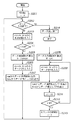
データ分割部101の動作を手順として示すと、図2に示すフローチャートのようになる。
【0050】
データ分割部101は動作を開始すると内部カウンタ(図2ではiと表記)を初期化する。具体的にはカウンタ i を0に設定し(ステップS201)、次にパックビッツ符号化データの入力が終了しているかどうかの判断を行う(ステップS202)。
【0051】
データの入力終了の判断は先に説明したように「長さ情報として128(16進数表記で80h、以下数字に続く括弧内は16進数表記を表す)を入力する」という方法もあるが、本実施形態ではdata_endから「TRUE=1」を入力することによりデータの入力終了を表すこととする。
【0052】
ステップS202においてデータ入力が終了していない(data_end = 0)と判断されると、データ分割部はencode_dataからデータが入力されるのを待つ。ここで、従来の技術で示した(3)及び(4)のようにパックビッツ符号化データは最初に長さ情報が入力されるため、具体的には長さ情報が入力されるのを待つことになる。
【0053】
encode_dataから最初の符号化データである長さ情報(図2ではLと表す)が入力されると(ステップS203)、データ分割部では入力されたLの値を参照して長さ情報が「同じデータが連続する数」を表しているか「異なるデータが連続する数」を表しているのかを判断する。具体的には、入力された長さ情報Lを正負の符号無しデータとし、閾値「128(80h)」と比較し(ステップS204)、Lが128より大きい場合は「同じデータが連続する数」、128未満の場合は「異なるデータが連続する数」と判断する。
【0054】
入力された長さ情報Lが128(80h)より大きい場合、データ分割部では長さ情報Lから同じデータの連続する数を求めて変数Nに代入する。本実施形態では同じデータが連続する数は2の補数により負の値として表現されているため、長さ情報Lから連続数の算出を行う(ステップS205)。具体的には
N = 256 − L +1
により連続数を求めてNに代入する。
【0055】
同じデータが連続する数を算出すると、データ分割部は再びencode_dataからパックビッツ符号化データが入力されるのを待つ。パックビッツ符号化データでは長さ情報が128以上の場合、次のデータは連続するデータの値が入力されるため、ここではデータ部(データ値)の入力を待つ。
【0056】
encode_dataからデータ部(図2ではDと表す)が入力されると(ステップS206)、データ分割部はnum出力(116)からデータ連続数であるNを、data出力(115)からデータ値であるDを出力する(ステップS207)。
【0057】
これにより、「データ値DがN個ある」という情報を後段に送り、再びステップS202によるデータ入力終了の判断に戻る。
【0058】
また、入力された長さ情報Lが128(80h)未満の場合、データ分割部では長さ情報Lから異なるデータが連続する数を求めて変数N’に代入する(ステップS208)。本実施形態では異なるデータが連続する数は長さ情報に1を加えた値であるため、具体的には
N’=L + 1
により異なるデータの数を求める。
【0059】
異なるデータの数を算出すると、データ分割部は再びencode_dataからパックビッツ符号化データが入力されるのを待つ。パックビッツ符号化データでは長さ情報が128以下の場合、長さ情報に続いて先に算出したN’の数だけデータの値が入力される。従ってここではデータ部(データ値)の入力を待つ。
【0060】
encode_dataからデータ部Dが入力されると(ステップS209)、データ分割部はnum出力(116)から1を、data出力(115)からデータ値Dを出力する(ステップS210)。これにより、「dataから出力したデータ値Dは1つである」という情報を後段に送る。
【0061】
dataからデータ値Dを出力すると、データ分割部は内部カウンタ i に1を加算し(ステップS212)、N'との比較を行う(ステップS212)。カウンタ値 i がN'より小さい場合は、引き続きデータ値が入力されるためステップS209に戻りencode_dataからデータ部が入力されるのを待つ。
【0062】
またステップS212により比較した結果カウンタ値iとN'の値が等しい場合は、データ値がN'の個数入力されたため、カウンタiを0に初期化して(ステップS213)、ステップ202によるデータ入力終了の判断に戻る。
【0063】
上記ステップS202〜213の動作を繰り返すことでパックビッツ符号化データの入力を行い、最後にステップ202においてdata_end=1が入力されてパックビッツ符号化データの入力終了が検出されると、データ分割部101はデータ出力を終了したことを表すためにend出力から1を出力して動作を終了する。
【0064】
図10にデータ分割部101の入出力タイミングチャートの一例を示す。
【0065】
図10において、clkはクロックを表し、各信号はclkに同期して入出力が行われる。data_valid、encode_data、data_ready及びdata_endの各信号はパックビッツ符号化データをデータ分割部に入力するための信号である。N、N'及びiはデータ分割部内で使用する変数及びカウンタ値を表し、valid、num、data、ready及びend信号はデータ部及び連続個数をデータ処理部102及びデータ結合部103に出力するための信号である。
【0066】
尚、図10ではencode_dataから入力されるパックビッツ符号化データのうち、長さ情報を表す部分には二重下線を引いて表示している。
【0067】
図10においてデータ分割部101の動作が開始すると、図10のタイミングt0において内部カウンタiの初期化動作が行われる(ステップS201)。その後、t1からdata_valid=1とすることによりencode_dataからデータ分割部にパックビッツ符号化データの入力が開始される。
【0068】
最初にデータ分割部に入力されるバックビッツ符号化データは長さ情報であるため、データ分割部はt1において入力された値253(=FDh)を長さ情報Lとして取得する(ステップS203)。その後取得した長さ情報Lと128(80h)を比較し(ステップS204)、
L < 128
の条件が満たされないため、取得した長さ情報Lを用いて、ステップ205に示した演算によりデータ連続数4(04h)を算出してNに格納する。
【0069】
その後、タイミングt2においてencode_dataから入力された値0(00h)をデータ値Dとして取得し(ステップS206)、タイミングt3においてnumからデータ連続個数Nを、dataからデータ値Dを出力した後(ステップS207)、ステップS202においてdata_endを参照してデータ入力が終了しているかどうかを判断する。
【0070】
タイミングt3ではdata_endから1が入力されていないため、ステップS203に進み、t3においてencode_dataから入力された値248(F8h)を長さ情報Lとして取得する(ステップS203)。そして長さ情報Lと128(80h)を比較し、ステップS205に進んでデータ連続数9(09h)を算出してNに格納する。そしてタイミングt4でencode_dataからデータ値Dとして1(01h)を取得して(ステップS206)、タイミングt4においてnumからデータ連続個数Nを、dataからデータ値Dを出力する。
【0071】
その後再びステップS202においてデータ入力終了の判断を行い、タイミングt5におけるdata_endは0であるのでステップS203に進み、タイミングt5においてencode_dataから入力されている6(06h)を長さ情報Lとして取得する。
【0072】
ステップS204により長さ情報Lと128(80h)を比較し、
L < 128
の条件を満たすため、ステップ208に示した式により長さ情報Lから長さ情報に続いて入力されるデータ値の個数7(07h)を算出してN’に格納(ステップS208)した後、eocnde_dataからデータ部Dの入力を待つ。
【0073】
タイミングt6においてencode_dataからデータ値Dとして「2(02h)」が入力されるとすると(ステップ209)、t7でnumからデータ連続数として1(01h)を、dataからデータ値Dである「2(0h)」を出力する(ステップS210)。出力値が「2」のまま変らないのは、第1回めのオーバーフロー時のマスク条件が、文字であるビット2が0である場合には、無彩色を示すビット0を0、すなわち、有彩色にするからである。そして内部カウンタiに1を加算して(ステップS211)、ステップ208で算出したN'と比較する(ステップS212)。
【0074】
タイミングt7では内部カウンタiの値は1であるためN’に格納したデータ入力個数である7と等しくないため、ステップS209に戻り再びencode_dataからデータ部Dが入力されるのを待つ。
【0075】
タイミングt7ではdata_validが1であるためencode_dataから入力されているデータは有効であるが、後述するデータ分割部103がデータの入力準備ができていないためready信号を0にしている。そのため、データ分割部でもdata_readyから0を出力してデータの取得を停止する。この時、encode_dataから入力されているデータは次のclkまで保持される。
【0076】
t8になりデータ分割部103がデータの入力が可能になりreadyから1が入力されると、データ分割部もdata_readyから1を出力してencode_dataからデータ値Dとして3(03h)が取得される。
【0077】
以後、ステップS209〜ステップS212により同様の動作をN’の回数だけ繰り返し、encode_dataから入力された値としてタイミングt9で2(02h)が出力される。理由は、文字であることを示すビット2が0であるので、ビット0がマスクされるからである。
【0078】
続く、t10で2(02h)、t11で3(03h)、t13で4(04h)、t14で3(03h)、t15で1(01h)を取得して、dataとしてタイミングt10で2(02h)、t11で2(02h)、t12で4(04h)、t14で2(02h)、t15で0(00h)を出力することになる。これらはマスク条件に従って行われるのは先に説明した通りである。
【0079】
タイミングt15では内部カウンタ i の値が7となりデータ入力個数N’と等しくなるため、ステップS212における比較の後、内部カウンタiを0に初期化し(ステップS213)、ステップS202に戻りdata_endを参照してデータ入力が終了しているかどうかを判断する。
【0080】
タイミングt15ではdata_endから1が入力されていないため、ステップS203に進み、タイミングt15においてencode_dataから入力された値253(FDh)を長さ情報Lとして取得し(ステップS203)、ステップS204で128(80h)を比較した後、ステップS205に進んでデータ連続数4(04h)を算出してNに格納する。そしてタイミングt16でencode_dataからデータ値Dとして0(00h)を取得して(ステップS206)、タイミングt17においてnumからデータ連続個数Nを、dataからデータ値Dを出力し、ステップS202に戻る。
【0081】
タイミングt17ではencode_endから1が入力されているため、データ分割部ではステップS202においてデータ入力が終了したと判断し、タイミングt18においてend出力から1を出力することによりデータ出力の終了を後段に知らせることにより(ステップS214)、本動作を終了する。
【0082】
図10のmasked_dataはデータ処理部102からの出力であり、本実施形態ではデータ処理部102においてデータ分割部101のdataから出力された値に対して、最初のオーバーフローの例を示した。すなわち、文字であることを示すビット2が0の場合、ビット0を0にするものである。しかし、次のオーバーフロー(2回めのオーバーフロー)の場合には、条件がまた異なることになることは明らかであろう。
【0083】
尚、本実施形態のデータ処理部102では図10に示す様にデータ処理部にdataから値が入力されてからclk遅延無くmasked_dataを出力しているため、masked_dataから出力されたデータと、データ分割部のnumから出力されているデータの連続個数を表す情報は同じタイミングでデータ結合部に与えられる。
【0084】
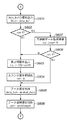
次に、実施形態におけるデータ結合部103の動作処理を図3乃至図8のフローチャートに従って説明する。
【0085】
データ連結部103がその処理を開始すると、num及びmasked_dataから最初のデータ連続個数及びデータ処理部102で処理されたデータ値の入力を待つ。
【0086】
データ連続個数及びデータ値が入力されると(ステップS301)、その値を初期値としてnumから入力されたデータ連続個数を内部変数cntに、masked_dataから入力されたデータ値を内部変数data_bufに格納する(ステップS302)。
【0087】
そしてcntに格納した値を参照し(ステップS303)、その値が1以外である場合はmasked_dataから入力されたデータ値が「同じデータ値が連続している」部分のデータ値であると判断し、その状態をデータ連続部で保持するために内部変数continueを1に設定する(ステップS304)。
【0088】
また、cntに格納した値が1である場合は、masked_dataから入力されたデータ値が「同じデータが連続していない」部分のデータ値であると判断し、この状態をデータ連続部で保持するために内部変数continueを0に設定する(ステップS305)。
【0089】
以上により、次のデータを入力するための準備が終了する。
【0090】
次にデータ結合部はデータ入力の終了を判断する(ステップS306)。本実施形態ではデータ分割部がend(118)が「1=high」にすることでデータの入力が終了したと判断し、図8の処理へと分岐する。end(118)から1が入力されていない場合には、データ分割部はnum(116)とmasked_data(121)から次のデータ連続数及びデータ値が入力されるのを待つ。
【0091】
データ連続数とデータ値が入力されると(ステップS307)、データ結合部は内部変数continueの値により分岐を行う(ステップS308)。continueの値が「同じデータが連続していない」部分を表す0である場合、さらにmasked_dataから入力されたデータ値と内部変数data_bufの値を比較する(ステップS309)。ここでmasked_dataから入力されたデータ値とdata_bufの値が異なる場合は図4の処理へ分岐する。また、masked_dataから入力されたデータ値とdata_bufの値が等しい場合は、図5の処理へ分岐して「同じデータが連続していない部分」を終了するための処理と、新たに「同じデータが連続している部分」が始まるための処理を行う。
【0092】
一方、ステップS308により内部変数continueの値が「同じデータが連続している」部分を表す1であった場合、同様にmasked_dataから入力されたデータ値と内部変数data_bufの値を比較し(ステップS310)、masked_dataから入力されたデータ値とdata_bufの値が異なる場合は図6の処理へ分岐する。また、masked_dataから入力されたデータ値とdata_bufの値が等しい場合は、図7へ分岐して「同じデータが連続している部分」を続けるための処理を行う。
【0093】
図4はデータ結合部における、内部変数continueが0かつmasked_dataから入力されたデータ値と内部変数data_bufの値が異なる場合(図3におけるステップS309がyes)の処理を表すフローチャートである。
【0094】
この場合、新たなパックビッツ符号化データを生成するためにdata_bufに格納されている値が必要であるためdata_bufに格納されている値をv_outから出力する(ステップS401)。そしてnumから入力されているデータ連続数を参照する(ステップS402)。
【0095】
データ連続数が1以外であれば、それはmasked_dataから入力されている値が1つ以上連続している事を表しているため、「同じデータが連続していない」部分はここで終了する。そのため内部変数continueの値を「同じデータが連続している」部分を表す1に設定し(ステップS403)、それまで続いていた「異なるデータが連続している」部分のデータ数が格納されている内部カウンタcntから1を減ずることで「異なるデータが連続する数」を表す長さ情報を求め、その長さ情報をv_outから出力する(ステップS404)。
【0096】
その後、内部変数cntを0に初期化して(ステップS405)から、numから入力されたデータ連続数をcntに加算し(ステップS406)、masked_dataから入力されたデータ値を内部変数data_bufに格納し(ステップS407)、次のデータ受け取り準備を行った後で、図3のステップS306に戻る。
【0097】
また、ステップS402においてnumから入力されたデータ連続数が1であった場合は、引き続き「同じデータが連続していない」部分であることを表している。この場合はまず内部変数cntの値を参照し、128(80h)であるかを判断する(ステップS408)。本実施形態では8ビットでパックビッツ符号データを表しているため、「同じデータが連続している」部分及び「同じデータが連続していない」部分の数は128までしか表す事が出来ない。そのため内部cntの値が128の場合、「同じデータが連続していない部分」が128回続いているという情報を出力する必要が生ずる。そのためステップS404により長さ情報を算出して(この場合「異なるデータが128個連続しているので」長さ情報として127(7Fh)が生成される)v_outから出力する。
【0098】
その後、内部変数cntを0に初期化して(ステップS405)から、numから入力されたデータ連続数(ここでは1)をcntに加算し(ステップS406)、masked_dataから入力されたデータ値を内部変数data_bufに格納し(ステップS4077)、次のデータ受け取り準備を行った後で図3のステップS306に戻る。
【0099】
ステップS408において内部変数cntの値が128でない(128未満)である場合は、numから入力されたデータ連続数(ここでは1)をcntに加算し(ステップS406)、masked_dataから入力されたデータ値を内部変数data_bufに格納して(ステップS407)、次のデータ受け取り準備を行った後で、図3のステップS306に戻る。
【0100】
図5はデータ結合部における、内部変数continueが0かつmasked_dataから入力されたデータ値と内部変数data_bufの値が同じ場合(図3におけるステップS309でNo)の処理を表すフローチャートである。
【0101】
この場合、一つ前の処理まではcontinueが0であるため「同じデータが連続しない」部分の処理を行っていたが、masked_dataから入力されているデータ値と内部変数data_bufの値が同じであるため「同じデータが連続しない」部分は一つ前のデータで終了していたことになる。そこで内部変数continueの値を「同じデータが連続している」部分を表す1に設定し(ステップS501)、内部変数cntの値を参照する(ステップS502)。cntの値が1でなければ、それまで続いていた「異なるデータが連続している」部分のデータ数を算出して出力する必要がある。
【0102】
そのためには、現在data_bufに格納されている値は「同じデータが連続している」部分に含まれるため、実際に「同じデータが連続していない」部分のデータ数は内部カウンタcntから1を減した値となる。また、「異なるデータが連続する数」を表す長さ情報は「異なるデータが連続している」数から1を減じた値であるため、ここでは内部変数cntから2を減じて長さ情報を求め、その長さ情報をv_outから出力する(ステップS503)。
【0103】
そしてmasked_dataから入力されるデータ値と同じデータがdata_bufに入っているため内部変数cntを1に設定(ステップS504)してから、numより入力されたデータ連続数をcntに加算(ステップS505)して次のデータ受け取り準備を行い、図3におけるステップS306に戻る。
【0104】
また、ステップS502においてcnt値が1であった場合は、cntの値にnumから入力されたデータ連続数を加算する(ステップS506)。
【0105】
本実施形態では8ビットでパックビッツ符号データを表しているため、「同じデータが連続している」部分の数は128までしか表す事が出来ないため、内部cntの値が129以上の場合、「同じデータが連続している」部分が128回続いているという情報を出力する必要が生ずる。そのため内部変数cntの値を参照し(ステップS507)、その値が129以上である場合はdata_buf に格納されているデータ値をv_outから出力し(ステップS508)、それに続いて「同じデータが128個連続している」ことを表す長さ情報である129(81h)をv_outから出力する(ステップS509)。尚、この129という長さ情報は、従来技術で説明した長さ情報とコードをテーブルとして記憶保持し、それを参考して求めてもいいし、同じデータがn個続く事を表す長さ情報が
256−n+1
であることから求めてもよい。ステップS508により長さ情報が出力されると、データ結合部は内部変数cntから後段にパックビッツ符号データとして出力した分の「128」を減じ(ステップS510)、次のデータ受け取り準備を行った後で、図3のステップS306に戻る。
【0106】
また、ステップS507において内部cntの値が129未満である場合は、図3のステップS306に戻ることになる。
【0107】
尚、ここではパックビッツ符号化に必要なデータ値は既にdata_bufに格納されているのでmasked_dataから入力されたデータ値を内部変数data_bufに格納する必要は無いが、格納してもよい。
【0108】
図6はデータ結合部における、内部変数continueが1かつmasked_dataから入力されたデータ値と内部変数data_bufの値が異なる場合(図3におけるステップS310がNo)の処理を表すフローチャートである。
【0109】
この場合masked_dataから入力されるデータ値をdta_bufの値が異なるため、「同じデータが連続している」部分はここで終了する。そのためdata_bufに格納されている値をv_outから出力する(ステップS601)。そしてnumから入力されているデータ連続数を参照する(ステップS602)。
【0110】
データ連続数が1以外であれば、それはmasked_dataから入力されている値が1つ以上連続している事を表しているため、再び「同じデータが連続している」部分が開始される。そのため内部変数continueの値は「同じデータが連続している」部分を表す1のままにしておき、それまで続いていた「同じデータが連続している」部分のデータ数が格納されている内部カウンタcntから長さ情報を求め(256からcntの値を減じ、さらに1を加えることにより求める)、その長さ情報をv_outから出力する(ステップS603)。
【0111】
その後、内部変数cntを0に初期化して(ステップS604)から、masked_dataから新たなデータ値を取得してdata_bufに格納し(ステップS605)、さらにnumから入力されたデータ連続数をcntに加算する(ステップS606)。こうして次のデータ受け取り準備が終了すると、図3のステップS306に戻ることになる。
【0112】
また、ステップS602においてnumから入力されたデータ連続数が1であった場合は「同じデータが連続していない」部分が始まる事を表している。この場合はまず内部変数continueの値を「同じデータが連続していない」部分を表す0に設定して(ステップS607)、内部変数cntの値を参照する(ステップS608)。
【0113】
cntの値が1以外であれば、「同じデータが連続している」部分のデータ数が格納されている内部カウンタcntから長さ情報を求め(256からcntの値を減じ、さらに1を加えることにより求める)、その長さ情報をv_outから出力する(ステップS603)。
【0114】
その後、内部変数cntを0に初期化して(ステップS604)から、masked_dataから新たなデータ値を取得してdata_bufに格納し(ステップS)、さらにnumから入力されたデータ連続数(ここでは1)をcntに加算する(ステップS606)。こうして次のデータ受け取り準備が終了すると、図3のステップS306に戻り、データ入力終了の判断を行うことになる。
【0115】
また、ステップS608により内部変数cntの値が1であった場合は、ステップS601で出力したデータ値を「同じデータが連続しない」部分の最初のデータとして処理を行う。そのためmasked_dataから新たなデータ値を取得してdata_bufに格納し(ステップS605)、さらにnumから入力されたデータ連続数(ここでは1)をcntに加算する(ステップS606)。こうして次のデータ受け取り準備が終了すると、図3のステップS306に戻る。
【0116】
図7はデータ結合部における、内部変数continueが1かつmasked_dataから入力されたデータ値と内部変数data_bufの値が同じ場合(図3におけるステップS310がyes)の処理を表すフローチャートである。
【0117】
この場合masked_dataから入力されるデータ値をdta_bufの値が同じため、「同じデータが連続している」部分はさらに続く。そのためデータが連続する数を求めるため内部変数cntにnumから入力されたデータ連続数を加算する(ステップS701)。
【0118】
また、本実施形態では8ビットでパックビッツ符号データを表しているため、「同じデータが連続している」部分及び「同じデータが連続していない」部分の数は図5の説明で述べた様に「128」までしか表す事が出来ない。そのため内部cntの値が129以上の場合、「同じデータが連続している」部分が128回続いているという情報を出力する必要が生ずる。そのため内部変数cntの値を参照し(ステップS702)、その値が129以上である場合はdata_bufに格納されているデータ値をv_outから出力し(ステップS703)、それに続いて「同じデータが128個連続している」ことを表す長さ情報である「129(81h)」をv_outから出力する(ステップS704)。尚、この「129」という長さ情報は従来技術で説明したテーブルを保持するようにし、それを参考して求めてもいいし、同じデータがn個続く事を表す長さ情報が
256−n+1
であることから求めてもよい。ステップS704により長さ情報が出力出力されると、データ結合部は内部変数cntから後段にパックビッツ符号データとして出力した分の「128」を減じ(ステップS705)、次のデータ受け取り準備を行った後で、図3におけるステップS306に戻る。
【0119】
また、ステップS702により内部変数cntが128以下の場合は、パックビッツ符号化に必要なデータは生成されないため、そのまま図3のステップS306に戻り、データ入力終了の判断を行うことになる。
【0120】
尚、図7のフローチャートではパックビッツ符号化に必要なデータ値は既にdata_bufに格納されているのでmasked_dataから入力されたデータ値を内部変数data_bufに格納する必要は無いが、格納してもよい。
【0121】
図8は図3のステップS306によりend(118)から1が入力され、データの入力が終了したと判断した場合のフローチャートを示す。
【0122】
図8ではまず始めに内部変数data_bufに格納しているデータ値をv_outから出力し(ステップS801)、その後内部変数continueの値を参照する(ステップS802)。
【0123】
continueの値が0の場合、ステップS801で出力したデータ値は「データが連続していない」部分の最後のデータ値であるため、内部変数cntから「異なるデータが連続する」部分の長さ情報を生成して出力する。具体的には内部変数cntの値から1を減じてv_outから出力する(ステップS803)。
【0124】
そして後段にデータの出力終了を知らせるためにv_end(134)に1を出力して(ステップS804)動作を終了する。
【0125】
一方ステップS802においてcontinueが1であった場合は、ステップS801で出力したデータ値は「データが連続している」部分のデータ値であるため、内部変数cntから「同じデータが連続する」部分の長さ情報を生成して出力する。具体的には内部変数cntの値をもちいて
256−cnt+1
の値を求め、v_outから出力する(ステップS805)。
【0126】
そして後段にデータの出力終了を知らせるためにv_end(134)に1を出力して(ステップS804)動作を終了する。
【0127】
尚、本実施形態のデータ結合部103では、図3乃至図8において内部変数data_bufに格納したデータ値をv_outから出力する場合は同時にd_valid(131)から1を出力し、また内部変数cntから生成した長さ情報をv_outから出力する場合は同時にl_valid(132)から1を出力する。これによりv_out(133)から出力されるデータの有効信号、及びv_outから出力したデータがパックビッツ符号化データのデータ部であるか長さ情報であるかの区別を後段に知らせている。
【0128】
また、図3乃至図8において、図6のステップS603や図7のステップS704の様に、num及びdataからデータ連続数及びデータ値の取得を行う事でv_outからデータ部および長さ情報の二つのデータを出力しなければならない場合は、v_outからの出力が終了するまでready(117)を0(すなわち、次のデータの入力要求をしない)にすることによりデータ結合部101及び画像処理部102からのデータ連続数及びデータ入力を停止させる必要がある。
【0129】
図11は、実施形態におけるデータ結合部103の入出力タイミングチャートの一例を示している。
【0130】
図11において、clkはクロックを表し、各信号はclkに同期して入出力が行われる。valid、num、masked_data、ready及びend信号はデータ分割部で生成されたデータ連続数及びデータ処理部102で生成されたデータ値をデータ結合部103に入力するための信号である。
【0131】
cnt、data_buf及びcontinueはデータ結合部内で使用する内部変数を表し、d_valid、l_valid、v_out及びv_end信号はパックビッツ符号化データのデータ部および長さ情報をデータ出力部104に出力するための信号である。
【0132】
尚、図11ではv_outから出力されるパックビッツ符号化データのうち、長さ情報を表す部分には二重下線を引いて表示している。
【0133】
図11においてタイミングt3においてnum及びmasked_dataから最初のデータ連続数及びデータ値が入力される(ステップS301)と、データ結合部103ではnumから入力された4(04h)を内部変数cntへ、masked_dataから入力された0(00h)を内部変数data_bufに格納する(ステップS302)。
【0134】
そしてステップ303によりcntの値を参照し、値が1ではないのでステップ304により内部変数continueを1に設定する。
【0135】
その後ステップ306によりデータ入力終了の判断を行い、endから1が入力されていないので再びnum及びmasked_dataからデータ連続数及びデータ値が入力されるのを待つ。
【0136】
タイミングt5においてnumから9(09h)、masked_dataから0(00h)が入力されると(ステップS307)、データ結合部103はステップS308により内部変数continueの値を参照し、その値が1であるのでステップ310に進みmasked_dataから入力されたデータ値とdata_bufに格納されている値の比較を行う。タイミングt3ではmasked_dataのデータ値とdata_bufの値がともに0(00h)で等しいため、データ結合部の動作は図7のステップS701へ進む。
【0137】
ステップ701により内部変数cntの値とnumから入力されたデータ連続数を加算し、加算後のcntの値を129と比較する(ステップS702)。加算した結果、内部変数cntの値は図11のタイミングt6に示す様に13(0Dh)であり、129よりも小さいため図3のステップ306に戻る。
【0138】
タイミングt6において再びステップ306によりデータ入力終了の判断を行い、endから1が入力されていないのでnum及びmasked_dataからデータ連続数及びデータ値が入力されるのを待つ。
【0139】
タイミングt7においてnumから1(01h)、masked_dataから2(02h)が入力されると(ステップS307)、データ結合部103はステップS308により内部変数continueの値を参照し、その値が1であるのでステップS310に進みmasked_dataから入力されたデータ値とdata_bufに格納されている値の比較を行う。タイミングt7ではmasked_dataのデータ値とdata_bufの値が異なるため、データ結合部の動作は図6のステップS601へ進む。
【0140】
ステップS601によりdata_bufに格納した値をd_validを1にすると同時にv_outから出力した後、numから入力された値を参照し(ステップS602)、その値が1であるためステップS607により内部変数continueを0に設定して「同じデータが連続しない」部分が始まる準備を行う。
【0141】
また、ステップS608により内部変数cntの値を参照し、1(01h)でないためステップS603により長さ情報
256−13+1
を算出してl_validを1にすると同時にv_outから244(F4h)を出力する。そして内部変数cntを0に初期化し(ステップS604)、masked_dataから入力されているデータ値である2(02h)をdata_bufに格納(ステップS605)、さらにnumから入力されているデータ連続数「1(01h)」をcntに加算して、cntの値を1(01h)にして図3のステップS306に戻る。
【0142】
尚、上記説明した動作はそれぞれ、ステップS601のdata_bufの値の出力をタイミングt7、ステップ607による内部変数continueに0を設定する動作をタイミングt7、ステップS603の長さ情報の出力をタイミングt8、ステップS605及びステップS606におけるデータ値の取得及びデータ連続数の加算をタイミングt8で行うことになる。
【0143】
また、タイミングt7で入力されたnum及びmasked_dataからデータ連続数及びデータ値については、データ結合部のv_outからデータ部および長さ情報の二つのデータを出力する必要があるため、タイミングt7においてデータ結合部のreadyから1を出力し、タイミングt7で入力されたnum及びmasked_dataから入力された値をタイミングt8まで保持して、タイミングt8においてnum及びmasked_dataから必要な値の取得を行っている。
【0144】
次のデータとしてタイミングt9でnumから1(01h)、masked_dataから2(02h)が入力されると、データ結合部はステップS308によりcontinue値を参照する。タイミングt8におけるcontinue値は0であるため、ステップS309によりmasked_dataから入力された値2と、data_bufの値を比較する。タイミングt8におけるdata_bufの値は2であるためデータ結合部の動作は図5のステップS501へ進むことになる。
【0145】
ステップS501により内部変数continueの値を「同じデータ連続する」部分を表す1に設定し、ステップS502により内部変数cntの値を参照する。このときのcntの値は1であるためステップS506に進んでcntの値とnumから入力されるデータ連続数の加算を行う。タイミングt9におけるnumの値は1(01h)であるためcntの値は2(02h)となる。
【0146】
次にステップS507においてcntの値を参照するが、この時のcntの値は上に示したように2であり、129未満であるためにそのまま図3のステップS306に戻る。
【0147】
タイミングt10及びタイミングt11における動作は、入力される値及び動作がタイミングt9の場合と同じであるためここでは説明を省略するが、タイミングt10及びタイミングt11の動作により内部変数cntの値はそれぞれタイミングt11では3(03h)、タイミングt12では4(04h)となり、continueの値は1のままである。
【0148】
タイミングt12においてnumから1(01h)、masked_dataから4(04h)が入力されると、データ結合部はステップS307からS308へ進み、内部変数continueが1であるためステップS310へ進む。そこでmasked_dataから入力された値である4と、data_bufに格納されている値である2を比較し、値が異なっているので図6のステップS601に進む。
【0149】
ステップS601によりv_outからdata_bufの値である2(02h)を出力し、numから入力されているデータ連続数が1であるためにステップS602からステップ607に進む。ここで「同じデータが連続連続しない」ことを表すようにcontinueに0を設定し、ステップS608によりcntの値を参照する。タイミングt12におけるcntの値は4(04h)であるため、ステップS603に進んでcntの値から「同じデータが連続する」数を示す長さ情報を算出してv_outから出力し、ステップS604においてcntを初期化した後、masked_dataのデータ値である4(04h)をdata_bufに格納し、初期化後のcntにnumから入力されたデータ連続数1(01h)を加算して図3のステップS306に戻る。
【0150】
尚、上記説明した動作はそれぞれ、ステップS601のdata_bufの値の出力がタイミングt12、ステップS607による内部変数continueに0を設定する動作をタイミングt12、ステップS603の長さ情報の出力がタイミングt13、ステップS605及びステップS606におけるデータ値の取得及びデータ連続数の加算はタイミングt13で行われる。
【0151】
また、タイミングt12で入力されたnum及びmasked_dataからデータ連続数及びデータ値については、データ結合部のv_outからデータ部および長さ情報の二つのデータを出力する必要があるため、タイミングt12においてデータ結合部のreadyから1を出力し、タイミングt12で入力されたnum及びmasked_dataから入力された値をタイミングt13まで保持して、タイミングt13においてnum及びmasked_dataから必要な値の取得を行っている。
【0152】
タイミングt14においてnumから1(01h)、masked_dataから2(02h)が入力されると、データ結合部はステップS307からS308へと処理を進め、内部変数continueが0であるためステップS309へ進む。そこでmasked_dataから入力された値である2と、data_bufに格納されている値である4を比較し、値が異なっているので図4のステップS401に進む。
【0153】
ステップS401によりv_outからdata_bufの値である4(04h)を出力し、numから入力されているデータ連続数が1であるためにステップS402からステップS408に進む。ここでの内部変数cntの値は1(01h)であるため、ステップS408からステップS406に進み、numの値を内部変数cntに加算する(これによりcntは2となる)。そしてステップS407でmasked_dataから入力された値をdata_bufに格納した後、図3のステップ306に戻る。。
【0154】
タイミングt15では、データ結合部はタイミングt14と同様の動作を行う。これによりv_outからは2(02h)が出力され、内部変数cntの値は1加算されて3に、data_bufの値はmasked_dataから入力された0(00h)となる。
【0155】
タイミングt17においてnumから4(04h)、masked_dataから0(00h)が入力されると、データ分割部はステップS307からS308へ進み、内部変数continueが0であるためステップS309へ進む。そこでmasked_dataから入力された値である0と、data_bufに格納されている値である0を比較し、値が同じであるので図5のステップS501に進む。
【0156】
ステップS501により内部変数continueの値を「同じデータ連続する」部分を表す1に設定し、ステップS502により内部変数cntの値を参照する。このときのcntの値は3であるためステップS503に進み、cnt値から「異なるデータが連続する」数を表す長さ情報を算出する。具体的にはcnt値である3から2を減じた値である1(01h)を長さ情報としてv_outから出力する。
【0157】
そしてステップS503によりcntに1を設定し、ステップS504によりnumから入力されたデータ連続数である4をcnt値に加算して5(05h)として、図3のステップS306に戻る。
【0158】
タイミングt18においてend(118)から1が入力されると、データ結合部ではステップS306においてデータ入力が終了したと判断して動作を終了するための処理のために図8のステップS801に進む。
【0159】
ステップS801においてdata_bufに格納されたデータ値をv_outから出力した後、ステップS802により内部変数continueの値を参照する。タイミングt18におけるcontinueの値は1であるため、ステップS805に進んでcntの値から「同じデータが連続する」部分を表す長さ情報を生成する。具体的にはcnt値である5(05h)を下式に用いて長さ情報として252(FCh)を算出してv_outから出力する。
256−cnt+1
その後、後段にデータの出力が終了した事を知らせるためにステップS804においてv_endから1を出力して動作を停止する。
【0160】
尚、上記説明した動作はそれぞれ、ステップS801のdata_bufの値の出力がタイミングt18、ステップS805による長さ情報の出力がタイミングt19、ステップS804のv_endからの1の出力はタイミングt20において行われる。
【0161】
また、タイミングt18でendから1が入力された状態については、データ結合部のv_outからデータ部および長さ情報の二つのデータを出力する必要があるため、タイミングt18においてデータ結合部のreadyから1を出力し、タイミングt18で入力されたendの状態をタイミングt19まで保持することにより、データ結合部はデータ入力の終了を了承する。
【0162】
上記説明した動作により、実施形態におけるデータ結合部103は通常のパックビッツ符号化データの並び順序である「連続する数+データ値」又は「異なるデータが連続する数+異なるデータ列」とは逆に、「データ値+連続する数」又は「異なるデータ列+異なるデータが連続する数」という順序でパックビッツ符号化データを出力する。
【0163】
データ出力部104は、データ結合部103から出力された符号化データを並び換え、通常のパックビッツ符号化データの順序になるように長さ情報とデータ部の並び順を入れ替えて出力する。
【0164】
実施形態におけるデータ出力部104が行う処理手順として示すと、図9のフローチャートのようになろう。
【0165】
データ出力部は動作を開始すると内部変数の初期設定を行う(ステップS901)。本実施形態におけるデータ出力部には内部変数として、v_outから入力される長さ情報を格納するバッファを示すL_locate、同様にv_outから入力されるデータ部のデータ値を格納するバッファを示すD_locate、及び長さ情報及びデータ部のデータ値を格納するための16個の8ビットのデータバッファdata_buf[15]〜data_buf[0]、data_buf[15]〜data_buf[8]の内容を出力する時に出力先のアドレスを示すアドレスバッファaddr_buf[1]及びdata_buf[7]〜data_buf[0]の内容を出力する時に出力先のアドレスを示すアドレスバッファaddr_buf[0]が存在する。
【0166】
ステップS901ではこれらの内部変数を、
L_locate = 0
D_locate = 1
addr_buf[0] = 0
addr_buf[1] = 1
data_buf[15]〜data_buf[0] = 0
のように設定する。
【0167】
内部変数の初期化が終了すると、データ出力部はデータ結合部からのデータの入力が終了しているかどうかの判断を行う(ステップS902)。データの入力終了の判断は、本実施形態ではv_endから1が入力されているかどうかで判断し、1が入力されているとデータの入力終了とする。
【0168】
ステップS902においてデータ入力が終了していない(v_end = 0)と判断されると、データ出力部はv_outからデータが入力されるのを待つ。本実施形態ではv_outから長さ情報が入力される場合はl_validから1が、データ部のデータ値が入力される場合はd_validから1が入力されるため、具体的にはデータ出力部はl_validの値を参照(ステップS903)及びd_validの値を参照(ステップS904)することによりv_outからので-タ入力を待つ。そしてv_endから1が入力されてデータ入力が終了するか、又はl_valid又はd_validが1になりv_outからデータが入力されるまで、図9のステップS902乃至904を繰り返す。
【0169】
ステップS903によりl_validから1が入力されたことを検知すると、データ出力部はv_outから入力される長さ情報をL_lodateが示す番号のdata_buf(以下data_buf[L_lodate]と示す)に格納し(ステップS905)、D_lodateが示していた値を新たな長さ情報格納位置としてL_locateに格納し、D_locateはD_locateが格納していた値に1を加える(ステップS906)。
【0170】
また、ステップS907では、ステップS906において設定されたL_locateの値を参照する。本実施形態ではL_locteの値より小さい番号のデータバッファには既にデータが格納されているため、L_locateの値が7より大きい場合はdata_buf[7]〜data_buf[0]の全てのデータバッファに値が格納されていることになる。
【0171】
そのためdata_buf[7]〜data_buf[0]の格納先を表すアドレスバッファaddr_buf[0]の値をaddressから出力すると共に、reencode_dataからdata_buf[7]〜data_buf[0]の値を出力する(ステップS908)。
【0172】
そしてaddr_buf[1]に格納されているアドレスを新たなアドレスとしてaddr_buf[0]に格納し、addr_buf[1]はaddr_buf[1]に格納していた値に1を加える。また、data_buf[15]〜data_buf[8]に格納された値をdata_buf[7]〜data_buf[0]に代入し、data_buf[15]〜data_buf[8]は0に初期化する。さらにD_locate及びL_locateの値からそれぞれ8を減じる(ステップS909)。
【0173】
これにより次のデータの取得準備が終了したのでデータ出力部はステップS905に戻りv_endから1が入力されるかv_outから新たなデータが入力されるのを待つ。
【0174】
尚、ステップS907において参照したL_locateの値が7以下である場合は、そのままステップS902に戻り、v_endから1が入力されるかv_outから新たなデータが入力されるのを待つ。
【0175】
また、ステップS903においてl_validの値が0であり、かつステップS904においてd_validから1が入力されたことを検知すると、データ出力部はv_outから入力されるデータ部のデータ値をD_lodateが示す番号のdata_buf(以下data_buf[D_lodate]と示す)に格納し(ステップS910)、D_locateが格納していた値に1を加える(ステップS911)。
【0176】
また、ステップS911において設定されたD_locateの値を参照する(ステップS912)。本実施形態ではステップS902、903、904におけるL_locteは7以下の値しか取らないため、D_locateの値が15より大きい場合はdata_buf[15]〜data_buf[8]の全てのデータバッファに値が格納されていることになる。
【0177】
そのためdata_buf[15]〜data_buf[8]の格納先を表すアドレスバッファaddr_buf[1]の値をaddressから出力すると共に、reencode_dataからdata_buf[15]〜data_buf[8]の値を出力する(ステップS913)。
【0178】
そしてaddr_buf[1]に格納していた値に1を加え、data_buf[15]〜data_buf[8]の内容を0に初期化すると共にD_locateの値から8を減じる(ステップS914)。
【0179】
これにより次のデータの取得準備が終了したのでデータ出力部はステップS902に戻りv_endから1が入力されるかv_outから新たなデータが入力されるのを待つ。
【0180】
尚、ステップS912において参照したD_locateの値が15以下である場合は、そのままステップS902に戻り、v_endから1が入力されるかv_outから新たなデータが入力されるのを待つ。
【0181】
また、ステップS902においてv_endから1が入力されてデータ入力が終了すると、データ出力部はL_locateの値を参照する(ステップS915)。L_locateの値が0以外である場合はデータバッファdata_buf[7]〜data_buf[0]のいくつかのバッファの中に未出力のデータが存在しているので、data_buf[7]〜data_buf[0]の格納先を表すアドレスバッファaddr_buf[0]の値をaddressから出力すると共に、reencode_dataからdata_buf[7]〜data_buf[0]の値を出力する(ステップS916)。
【0182】
その後、後段にデータの出力終了を知らせるためにreencode_endから1を出力して(ステップS917)動作を終了する。
【0183】
またステップS915においてL_locateの値が0であった場合は、データバッファの中に出力されていないデータが無いため、ステップS917に進みreencode_endから1を出力してデータの出力終了を知らせた後、動作を終了する。
【0184】
尚、上記説明におけるステップS909及びS914においてreencode_dtaからデータを、またaddressからアドレスを出力する際にはreencode_validを1にすることを付け加えておく。
【0185】
図12、図13は、本実施形態におけるデータ出力部104に、図11に示すタイミングでd_valid、l_valid、v_out及びv_endが入力された場合のデータ出力部の動作を表す図であり、内部変数及び出力信号の値の遷移を示しめしている。
【0186】
図12における先頭にあるのは、図11のタイミングt0におけるデータ出力部の状態である。同図同箇所において、1201は図11における時間(タイミング)、1202は1201で表した時間におけるデータ出力部への入力値を表している。、また、1202は1201で表した時間における内部変数の値を、1203は同じ様に1201で表した時間におけるデータ出力部の出力値を表している。尚、図12のタイミングt0では図9のステップS901において内部変数を初期化した状態が示されている。尚、data_buf[0]〜data_buf[15]の値は0に設定されるが、タイミングt0ではv_outから入力されるデータと区別をするためにdata_bufの値は空欄で示している。
【0187】
タイミングt7では、v_outからデータ部のデータ値が入力された状態を表している。この時のデータ出力部104はステップS904によりd_validが1であることを検知し、D_locateの値が1であることからステップS910によりv_outから入力された値をdata_buf[1]に格納すると共に、ステップ911によりD_locateの値に1を加算して2とする。その後、ステップS912によりD_locateの値を参照し、15以下であるためにステップS902に戻る。上記動作後は、タイミングt8に示す状態になる。
【0188】
図12のタイミングt8は、v_outから長さ情報が入力された状態を表している。この時、データ出力部104はステップS903によりl_validが1であることを検知し、L_locateの値が0であることからステップS905によりv_outから入力された値をdata_buf[0]に格納すると共に、ステップS906によりD_locateに格納されていた値2をL_locateに格納し、D_locateの値2に1を加算して3とする。その後、ステップS907によりL_locateの値を参照し、7以下であるためにステップS902に戻る。上記動作後の内部変数の状態はタイミングt12のようになる。
【0189】
同様にしてタイミングt12、t14、t15、及び、図13におけるタイミングt18ではd_validから1が入力されるため、D_locateの値が示すdata_bufにv_outから入力されるデータ部のデータ値を格納し、D_locateの値を1加算する。
【0190】
また、タイミングt17ではl_validから1が入力されるため、L_locateの値が示すdata_bufにv_outから入力された長さ情報を格納し、D_locateの値をL_locateへ格納してD_locateの値を1加算する。
【0191】
タイミングt19ではv_outから長さ情報が入力されている。このときL_locateの値は7であるため、ステップS905によりv_outから入力された値FChはdata_buf[7]に格納され、その後ステップS906によりL_locateにはD_locateの値である9が、またD_locateには10が格納される。
【0192】
この時、ステップS907においてL_locateを参照するとL_locateの値は7以上であるため、ステップS908によりaddressからaddr_buf[0]の値である0が、またreencode_dataからはdata_buf[0]〜data_buf[7]の内容を出力する。
【0193】
その後、ステップS909によりaddr_buf[0]の内容をaddr_buf[1]に格納されている1に設定し、addr_buf[1]の値は1を加算して2とする。またdata_buf[8]〜data_buf[15]に格納された値をdata_buf[0]〜data_buf[7]に設定して、data_buf[8]〜data_buf[15]を0に初期化する(図12、図13内では空欄で表す)。さらにL_locate及びD_locateの値から8を減じてL_locateの値を1に、D_locateの値を2にする。
【0194】
尚、上記ステップS905〜S909の動作結果は図13のタイミングt20に示されている。また、上記説明においてaddress及びreencode_dataからアドレス及びデータを出力する際はreencode_validからも1を出力する。
【0195】
図13のタイミングt20において、v_endから1が入力されている状態を表している。この時データ出力部104はステップS902によりv_endが1であることを検知し、ステップS905によりL_locateの値を参照する。タイミングt20ではL_locateの値は1であるため、ステップS916によりdata_buf[0]〜data_buf[7]に残ったデータの出力を行う。そのため、reencode_validから1を出力すると共に、addressからはaddr_buf[0]の値である1をreencode_dataからはdata_buf[0]〜data_buf[7]の値を出力する。
【0196】
その後、ステップS917によりreencode_endから1を出力してデータ出力部の動作を終了する。
【0197】
上記説明において、ステップS916における動作結果は図13のタイミングt21に、ステップS917における動作結果は図13のタイミングt22のようになる。
【0198】
以上説明した様に本実施形態によれば、パックビッツ符号化装置ではパックビッツ符号化データを入力し、パックビッツ符号化データのままデータ部に対して所定の処理を行った後で再度パックビッツ符号化処理(パックビッツ符号の再構成)を行う事が可能となる。本実施形態では具体例として、図10においてencode_dataから入力された14個のパックビッツ符号化データが、データ処理部により最下位ビットを0にすることにより図11のv_outに示す様に9個のパックビッツ符号化データに圧縮する事が出来るようになる。
【0199】
なお、実施形態では、像域情報をパックビッツ符号化する場合について説明したが、画像データである各画素値を符号化対象としても構わない。この場合、先に示したオーバーフローの回数とマスクするビットの関係は、画素値のLSBから上位に向かうNビット(N=オーバーフロー回数)をマスクするようにすれば良いであろう。
【0200】
また、実施形態では、パックビッツ符号化を例にして説明したが、同じデータの連続する数とそのデータ、異なるデータが連続する数とそのデータ列で表現される符号化に対して適用できるものであるから、上記実施形態によって本願発明が限定されるものではない。
【0201】
<第2の実施形態>
図16は本発明のパックビッツ再符号化部の他の例(第2の実施形態)である。
【0202】
図16のパックビッツ符号化装置はencode_dataからパックビッツ符号化データだけでなくパックビッツ符号化を行う前の生データの入力も可能にするため、データ分割部1401にraw_data信号(1410)が追加されている。
【0203】
本第2の実施形態のパックビッツ符号化装置ではraw_dataから0が入力されると、データ分割部1401は図2に示す様にencode_data(111)からパックビッツ符号化データが入力された場合の動作を行い、raw_dataから1が入力されるとencode_data(111)からパックビッツ符号化を行う前の生データが入力された場合の動作を行う。
【0204】
生データが入力された場合のデータ分割部1401の動作を具体的に説明すると、encode_data(111)から生データが入力されると、入力されたデータはdata(115)からデータ処理部102へ出力し、それと同時にnum(116)からデータ連続数として1(01h)を出力する。
【0205】
これによりデータ結合部103及びデータ処理部104では、データ分割部1401から出力された後、データ処理部102で処理されたデータ値を「データ連続数が1」であるデータとしてパックビッツ符号化処理を行う。
【0206】
以上の構成により、図16のパックビッツ符号化装置はパックビッツ符号化データ及び生データのどちらを入力しても、パックビッツ符号化データを生成して出力することが可能になる。
【0207】
以上述べたように本第1、第2の実施形態によれば、パックビッツ符号化を行った符号化データを複号処理することなく、パックビッツ符号化データを長さ情報とデータ部に分割し、データ部のデータ値に対して処理を行い、処理後のデータ値と長さ情報を用いて新たなパックビッツ符号化データを再構成することが可能となり、再符号化する際に多くのメモリを必要とせず、高速な再符号化が行えるようになる。
【0208】
また、実施形態では、複写機に適用させた例を説明したが、本願発明はこれに限定されるものではない。
【0209】
更に、実施形態では、再符号化する際に、マスクする(0にする)ビット位置を決定する例を示したが、1にセットすることで対処しても構わない。すなわち、正論理/負論理のいずれを採用しても構わない。要するに、再符号化する際に、データの取り得る種類の数を減らす方向にビット変更すれ良い。なぜなら、この結果、同じデータの連続する割合が高くできることになり、より高い圧縮率が期待できるからである。
【0210】
また、実施形態で説明したパックビッツ再符号化部15が有する夫々の構成要素をフローチャートを用いて説明した。かかる説明から明らかなように、その機能と同機能をコンピュータプログラムで実現させても構わない。すなわち、本発明はコンピュータプログラムもその範疇とする。また、通常、コンピュータプログラムは、それが記憶されたCDROM等のコンピュータ可読記憶媒体を装置にセットし、システムにコピーもしくはインストールすることで実行可能となるわけであるから、本発明はかかるコンピュータ可読記憶媒体をもその範疇とするのは明らかである。
【0211】
以上であるが、上記実施形態での記載に従って本発明にかかる実施態様を列挙すれば次の通りである。
【0212】
[実施態様1] 同じデータの連続数を示す連続数コード部と前記データを示すデータ部、及び、異なるデータ列の連続数を示す連続数コード部と前記異なるデータ列を示すデータ部のデータ形式で表現される符号化データを、前記データ形式に再符号化する符号化方法であって、
前記データ形式の符号化データのストリームを入力する工程と、
入力したストリームから、連続数コードとデータ部とに分割する工程と、
分割したデータ部の所望とするビットを変更する工程と、
変更したデータ部と前記連続数コード部に基づき、前記データ形式に再構成する工程と、
再構成したデータを再符号化データストリームとして出力する工程と
を備えることを特徴とする符号化方法。
【0213】
[実施態様2] 更に、前記変更する工程に対し、変更するビット位置を指定する工程を有することを特徴とする実施態様1に記載の符号化方法。
【0214】
[実施態様3] 前記指定工程は、データ部の所定のビットの情報に基づいて変更するビット位置を指定することを特徴とする実施態様2に記載の符号化方法。
【0215】
[実施態様4] 前記符号化データのデータ部は、画像データの画素の複数の像域属性のフラグビットで構成されることを特徴とする実施態様1乃至3のいずれか1項に記載の符号化方法。
【0216】
[実施態様5] 前記符号化データは、パックビッツ符号化データであることを特徴とする実施態様1乃至4のいずれか1項に記載の符号化方法。
【0217】
[実施態様6] 同じデータの連続数を示す連続数コード部と前記データを示すデータ部、及び、異なるデータ列の連続数を示す連続数コード部と前記異なるデータ列を示すデータ部のデータ形式で表現される符号化データを、前記データ形式に再符号化する符号化装置であって、
前記データ形式の符号化データのストリームを入力する入力手段と、
入力したストリームから、連続数コードとデータ部とに分割する分割手段と、
分割したデータ部の所望とするビットを変更する変更手段と、
変更したデータ部と前記連続数コード部に基づき、前記データ形式に再構成する再構成手段と、
再構成したデータを再符号化データストリームとして出力する出力手段と
を備えることを特徴とする符号化装置。
【0218】
[実施態様7] 同じデータの連続数を示す連続数コード部と前記データを示すデータ部、及び、異なるデータ列の連続数を示す連続数コード部と前記異なるデータ列を示すデータ部のデータ形式で表現される符号化データを、前記データ形式に再符号化する符号化装置として機能するコンピュータプログラムであって、
前記データ形式の符号化データのストリームを入力する入力手段と、
入力したストリームから、連続数コードとデータ部とに分割する分割手段と、
分割したデータ部の所望とするビットを変更する変更手段と、
変更したデータ部と前記連続数コード部に基づき、前記データ形式に再構成する再構成手段と、
再構成したデータを再符号化データストリームとして出力する出力手段と
して機能することを特徴とするコンピュータプログラム。
【0219】
[実施態様8] 実施態様7に記載のコンピュータプログラムを格納することを特徴とするコンピュータ可読記憶媒体。
【0220】
なお、上記実施態様6、7、8に対して、実施態様2乃至5が付加可能であることは明らかである。
【0221】
【発明の効果】
以上説明したように本発明によれば、パックビッツ符号化データの如く、同じデータの連続数を示す連続数コード部と前記データを示すデータ部、及び、異なるデータ列の連続数を示す連続数コード部と前記異なるデータ列を示すデータ部のデータ形式で表現される符号化データを、復号処理することなく、同じデータ形式に再符号化し、圧縮率を向上させることが可能になる。
【図面の簡単な説明】
【図1】実施形態におけるパックビッツ再符号化部のブロック構成図である。
【図2】実施形態におけるデータ分割部101の動作処理内容を示すフローチャートである。
【図3】実施形態におけるデータ結合部103の動作処理内容を示すフローチャートである。
【図4】実施形態におけるデータ結合部103の動作処理内容を示すフローチャートである。
【図5】実施形態におけるデータ結合部103の動作処理内容を示すフローチャートである。
【図6】実施形態におけるデータ結合部103の動作処理内容を示すフローチャートである。
【図7】実施形態におけるデータ結合部103の動作処理内容を示すフローチャートである。
【図8】実施形態におけるデータ結合部103の動作処理内容を示すフローチャートである。
【図9】実施形態におけるデータ出力部104の動作処理内容を示すフローチャートである。
【図10】実施形態におけるデータ分割部101及びデータ処理部102の入出力タイミングチャートである。
【図11】実施形態におけるデータ結合部103の入出力タイミングチャートである。
【図12】実施形態におけるデータ出力部104の動作にともなう内部状態の遷移図である。
【図13】実施形態におけるデータ出力部104の動作にともなう内部状態の遷移図である。
【図14】実施形態が適用するデジタル複写機のブロック構成図である。
【図15】図14における像域情報符号化部のブロック構成図である。
【図16】第2の実施形態におけるパックビッツ再符号化装置のブロック構成図である。[0001]
BACKGROUND OF THE INVENTION
The present invention relates to a technique for processing encoded data and re-encoding.
[0002]
[Prior art]
Packbits encoding is known as a data compression encoding technique. This pack bits encoding is one of the run-length encodings, and can be decoded without losing information before encoding, that is, lossless encoding.
[0003]
In the following, description of Packbits encoding is performed on the assumption that one data, which is a unit for performing encoding, is composed of 8 bits (the data is, for example, 8-bit multivalued pixel data). Further, data before encoding is called raw data, and a stream of raw data before encoding is called a raw data string.
[0004]
Packbits coding distinguishes raw data sequences into “parts where the same data is continuous” and “parts where different data is continuous”, and adds “length information” of the data to each part. Is. For “parts where the same data is continuous”, “consecutive number + data”, and for “parts where different data is continuous”, “number of consecutive different data + different data strings”. To express. The data string generated by this processing is output as packbits encoded data.
[0005]
Assume that a raw data string (24 pieces of data) as shown in (1) below is input. Individual data is 8 bits (data in the range of 0 to 255).
0,0,0,0,1,2,3,4,4,4,4,4,4,4,4,5,5,6,7,8,8,9,10,10… (1 )
In this case, the raw data column
0,0,0,0,
1,2,3,
4,4,4,4,4,4,4,4,
5,5,
6,7,
8,8,
9,
10,10 (2)
In this way, a distinction is made between “a portion where the same data continues” and “a portion where different data continues”. Then, “length information” is added to each portion, and the data portion is compressed to only one regarding “the portion where the same data continues”.
[0006]
0,0,0,0, ⇒ (-4), 0,
1,2,3, ⇒ (3), 1,2,3,
4,4,4,4,4,4,4,4, ⇒ (-8), 4,
5,5, ⇒ (-2), 5,
6,7, ⇒ (2), 6,7,
8,8, ⇒ (-2), 8,
9, ⇒ (1), 9,
10,10 ⇒ (-2), 10… (3)
In (3), “length information” is enclosed in parentheses. The reason why the “length information” is indicated by a positive or negative value is to distinguish whether consecutive portions are the same data or different data. That is, a negative number represents “a continuous portion of the same data”, and a positive number represents “a continuous portion of different data”. Then, the “length information” is embedded in the data string as “length code data” having a width of 8 bits like the data and is output. That is, the 8 most significant bits MSB of the length code data are handled as positive and negative sign bits.
[0007]
Also, like the above value “9”1For data that exists in isolation,There is one different dataIs defined. for that reason,the sameThe number of continuous data is at least two.
[0008]
The relationship (table) between the length code data and “the number of consecutive data of the same value” and “the number of consecutive data of different values” is as follows (Note: “0x” is a hexadecimal number) Showing).
[0009]
Number of consecutive different data Length code data
1 0x00
2 0x01
3 0x02
::
127 0x7E
128 0x7F
Same dataNumber of consecutive length code data
2 (-2) 0xFF
3 (-3) 0xFE
::
127 (-127) 0x82
128 (-128) 0x81
Therefore, when the above-described raw data string (1) is pack-bit encoded, the following encoded data string (4) is generated.
FD, 00,02,01,02,03, F9,04, FF, 5,01,06,07, FF, 08,00,09, FF, 10… (4)
As mentioned above, in pack bits encoding, the number of consecutive same data is2Can represent up to 128, the consecutive number of different data is1Up to 128 can be expressed. Therefore, if the number of consecutive identical data is 129 or more, up to 128 consecutive codes (length code data + continuous data) are generated, and for the 129th and later, the 129th data is generated. A code as a starting point is generated. The same applies to the case where different data are consecutive.
[0010]
As shown in the above table, 0x80 is not generated as “length code data” in Packbits encoding. Therefore, “0x80” may be defined as end-of-list code data representing the end of the encoded data string.
[0011]
Hereinafter, the “length code data” in the Packbits encoded data is expressed by “length information”, and the portion indicating the actual data value output following the length information is expressed by the term “data portion”. I will do it.
[0012]
As described above, in Packbits encoding, the amount of data after encoding decreases (the compression rate increases) as the number of times the same value of data appears continuously increases.
[0013]
[Problems to be solved by the invention]
In general, when compressing data, the compression code is set with a target of 1/2 or less (compression ratio of 2 or more) or 1/4 or less (compression ratio of 4 or more) with respect to the amount (size) of raw data. Is often performed. In the case of packbits encoding, the compression ratio improves when three or more of the same data are continuous. However, if different data are often continuous, the data corresponding to the length information is added. The amount will increase.
[0014]
Therefore, if the target data amount cannot be reached by performing Packbits encoding, it cannot be realized unless changes are made so that the same data continues. Here, if a certain bit of raw data is fixed to 0, the number of types of values that can be taken is reduced to half, and the probability that the same values continue will inevitably increase. Therefore, when such data is compressed, High compression ratio. For example, in the case of multi-value pixels as an example of compression encoding target, when LSB is set to 0, pixel values expressed by 2n, 2n + 1 (n is 0, 1, 2,...) Are both rounded to “2n”. In the case of a halftone image, the density and brightness of adjacent pixels are originally small, so that the same value is more likely to be obtained by changing the bit value as described above. That is, it will be understood that if the bit changing process is performed, a higher compression ratio is obtained. Similarly, if appropriate 2 bits are set to 0, furtherhighAs you can see, the compression ratio.
[0015]
However, in order to perform the above rounding processing on each piece of data of the original raw data set (for example, multi-value image data), processing proportional to the amount of data is required, and high processing speed cannot be expected. . For this purpose, a memory for storing the entire original raw data is also required.
[0016]
Therefore, the present invention is different from the continuous number code part indicating the continuous number of the same data, the data part indicating the data, and the continuous number code part indicating the continuous number of different data strings, such as Packbits encoded data. It is an object of the present invention to provide a technique for re-encoding encoded data expressed in a data format of a data portion indicating a data string into the same data format at a higher compression rate without decoding.
[0017]
[Means for Solving the Problems]
In order to solve this problem, for example, the encoding method of the present invention includes the following steps. That is,
The first type of encoded data represented by a continuous code part indicating the number of consecutive data and the data part indicating the data, or a continuous code part indicating the number of consecutive different data and the data of the different data Sequentially input the second type of encoded data represented byin frontAn encoding method for re-encoding into encoded data of the encoded data format of the first or second type,
A determination step of determining whether the target encoded data is the encoded data of the first type or the second type based on the continuous number code portion of the input encoded data;
When it is determined in the determination step that the encoded data of interest is the first type of encoded data, the continuous number information indicated by the continuous code portion in the encoded data of interest and the data portion are indicated. Output data,
When it is determined in the determination step that the encoded data of interest is the second type of encoded data, when outputting individual data of the data portion in the encoded data of interest, the continuous number of the same data is An encoded data separation step of outputting continuous number information indicating "1";
Among the continuous number information and data output from the encoded data separation step, a data change step of changing a part of the data to a predetermined value and outputting the data, and
The continuous number information output from the encoded data separation step and the data processed in the data change step are input, and the first or second type of encoded data is continuous without being decoded. A reconfiguration step of reconfiguring the number code portion and the data portion;
The reconstructed continuous number code portion and the data portion are output as re-encoded data, and
The reconstruction process includes
Each time the continuous number information from the encoded data separation step and the set of changed data from the data change step are input, whether the same data is being counted or different data is being counted, and A determination step of determining whether the current input data is equal to the data input immediately before;
If the number of consecutive data of the same data is being counted in the determination step and the current input data is equal to the data input immediately before, the continuous data updated by the previous input is added to the current input continuous data information. By adding the information, the current continuous number information is updated,
In the determining step, when the number of consecutive different data is being counted, and the current input data is not equal to the data input immediately before, the current input continuous number information is updated with the previous input. By adding the piece information, the current continuous piece information is updated,
In the determining step, the number of consecutive data of the same data is being counted and the current input data is not equal to the data input immediately before, or the number of consecutive data of different data is being counted and the current data is being counted. When the input data is equal to the data input immediately before, a step of generating a data part from the unoutput data that was being counted and a continuous number code part from the counted continuous number information is provided.
[0018]
DETAILED DESCRIPTION OF THE INVENTION
Embodiments according to the present invention will be described below with reference to the accompanying drawings.
[0019]
<Overview>
In the embodiment, a digital copying machine will be described as an example.
[0020]
FIG. 14 is a block diagram of the digital copying machine in the embodiment. In the figure,
[0021]
On the other hand, the data of each color component output from the
[0022]
The contents to be determined by the image
[0023]
Whether or not it is a character line image is determined by whether or not the luminance change between the target pixel and the adjacent pixel is steep (exceeds a threshold). When a predetermined number of pixels determined to be steep are continuous, it is determined as a character / line image, and when it is less than the predetermined number, it is determined as a halftone dot. Accordingly, whether or not the character is in a halftone dot is determined based on whether or not the pixel of interest is a character, and there are a plurality of pixels determined to be halftone dots within a predetermined distance range therefrom. If it is determined that the image is neither a character line drawing nor a halftone dot, it may be determined as a halftone area.
[0024]
The determination of whether the color is a chromatic color or achromatic color is determined as an achromatic color when the difference in luminance value of each luminance color component RGB of the pixel of interest is equal to or less than a threshold value. In order to make a more accurate determination, if even one chromatic color pixel exists in the vicinity including the target pixel, the target pixel is determined to be a chromatic color.
[0025]
In addition, the character thickness information may be obtained by counting the number of pixels determined to be a character line drawing in a direction orthogonal to the direction along the edge of the pixel determined to be a character.
[0026]
As described above, the image
Bit Meaning
7 Reservations (0)
6 Reservation (0)
5 Character thickness
4
3 Reservation (0)
2 characters Character line drawing = 1, Non-character line drawing (halftone) = 0
1 Character in halftone dot Character / line drawing in halftone dot = 1, otherwise = 0
0 Achromatic color Achromatic color = 1, chromatic color = 0
It was.
[0027]
The image
[0028]
In the above configuration, the configuration of the image area
[0029]
In the figure,
[0030]
A pack
[0031]
In the above configuration, the
[0032]
As a result, the
[0033]
In the embodiment, the number of overflows (OF), mask conditions and bits of image area information are as follows:
OF count condition & mask bit
0 No mask
1 If character flag (bit 2) is 0, achromatic color (bit 0) is 0
If the 2 character flag is 0, the character thickness (
If the 3 character flag is 0, set the halftone character flag (bit 1) to 0.
0 except for 4 character flags
5 All 0
It was.
[0034]
If the above contents are explained in an easy-to-understand manner, it means that the attribute of a pixel is changed to an attribute that includes it. For example, the reason that the achromatic color is changed to the chromatic color at the first overflow is that the achromatic color space is included in the chromatic color space.
[0035]
In the
[0036]
Further, in the above processing, the processing itself of the
[0037]
Focusing on the fact that the object to be re-encoded by the
[0038]
<Description of
FIG. 1 is a block diagram of a Packbits re-encoding unit in the present embodiment. Hereinafter, the configuration and processing contents will be described with reference to the block diagram of FIG.
[0039]
In FIG. 1,
[0040]
The
[0041]
Further, the
[0042]
[0043]
[0044]
In the present embodiment, in addition to num and masked_data, the data value and the ready signal ready and end signal end described in the
[0045]
The encoded data generated by the data combining unit is output using v_out (133). However, the encoded data output from the
[0046]
Therefore, in the data combination unit of the present embodiment, in order to determine whether the data output from v_out is length information or data portion, the length information valid signal is l_valid and the data portion valid signal. The encoded data is output using d_vald, an end signal v_end (134) indicating the end of data output.
[0047]
A
In the present embodiment, the rearranged Packbits encoded data is output from the reencode_data (141) as 64 bits by collecting 8 data, and the subsequent memory address for storing the data output from the reencode_data is determined from the address (142). Output. When data and address are output from reencode_data and address, 1 is output from reencode_vald which is a valid signal to indicate that the data and address are valid.
[0048]
When the output of the address and data from the data output unit is completed, 1 is output from reencode_end (143) to notify the subsequent stage that the output of data is completed.
[0049]
The operation of the
[0050]
When starting the operation, the
[0051]
As described above, there is a method of “entering 128 length information (80h in hexadecimal notation, and the hexadecimal notation in parentheses following the number)” as described above. In the embodiment, the data input end is indicated by inputting “TRUE = 1” from data_end.
[0052]
If it is determined in step S202 that data input has not ended (data_end = 0), the data division unit waits for data to be input from encode_data. Here, as shown in (3) and (4) in the prior art, since the length information is input first for the packbits encoded data, specifically, the input of the length information is waited. It will be.
[0053]
When length information (represented as L in FIG. 2) that is the first encoded data is input from encode_data (step S203), the data dividing unit refers to the input value of L and the length information is “same. It is determined whether it represents “the number of consecutive data” or “the number of consecutive different data”. Specifically, the input length information L is set as positive / negative unsigned data and compared with a threshold value “128 (80h)” (step S204), and when L is larger than 128, “the number of consecutive same data” , Less than 128, it is determined that “the number of consecutive different data”.
[0054]
When the input length information L is larger than 128 (80h), the data dividing unit obtains the continuous number of the same data from the length information L and substitutes it for the variable N. In the present embodiment, since the number of consecutive identical data is expressed as a negative value by two's complement, the number of consecutive numbers is calculated from the length information L (step S205). In particular
N = 256−
The continuous number is obtained by substituting for N.
[0055]
When the number of consecutive identical data is calculated, the data dividing unit again waits for input of packbits encoded data from encode_data. When the length information is 128 or more in packbits encoded data, the next data is input with a continuous data value, and therefore, the input of the data portion (data value) is awaited here.
[0056]
When a data part (denoted as D in FIG. 2) is input from encode_data (step S206), the data dividing part outputs N from the num output (116), and the data value from the data output (115). D is output (step S207).
[0057]
Thereby, the information that “there are N data values D” is sent to the subsequent stage, and the process returns to the determination of the end of data input in step S202.
[0058]
If the input length information L is less than 128 (80h), the data dividing unit obtains the number of consecutive different data from the length information L and substitutes it for the variable N ′ (step S208). In this embodiment, the number of consecutive different data is a value obtained by adding 1 to the length information.
N ′ = L + 1
To obtain the number of different data.
[0059]
When the number of different data is calculated, the data division unit again waits for input of Packbits encoded data from encode_data. If the length information is less than or equal to 128 in the packbits encoded data, the data value is input by the number of N 'calculated previously following the length information. Therefore, the input of the data part (data value) is awaited here.
[0060]
When the data part D is input from encode_data (step S209), the data dividing
[0061]
When the data value D is output from data, the data dividing unit adds 1 to the internal counter i (step S212), and performs comparison with N ′ (step S212). If the counter value i is smaller than N ′, the data value is continuously input, so the process returns to step S209 to wait for the data part to be input from encode_data.
[0062]
If the counter value i compared in step S212 is equal to the value of N ′, since the number of data values N ′ has been input, the counter i is initialized to 0 (step S213), and the data input in step 202 is completed. Return to Judgment.
[0063]
The pack bits encoded data is input by repeating the operations of steps S202 to S213. When data_end = 1 is finally input in step 202 and the input end of the pack bits encoded data is detected, the data dividing unit In order to indicate that the data output has ended, 101
[0064]
FIG. 10 shows an example of an input / output timing chart of the
[0065]
In FIG. 10, clk represents a clock, and each signal is input / output in synchronization with clk. The data_valid, encode_data, data_ready, and data_end signals are signals for inputting packbits encoded data to the data dividing unit. N, N ′, and i represent variables and counter values used in the data dividing unit, and valid, num, data, ready, and end signals are used to output the data unit and the continuous number to the
[0066]
In FIG. 10, the portion representing the length information in the packbits encoded data input from encode_data is displayed with a double underline.
[0067]
When the operation of the
[0068]
Since the Backbits encoded data first input to the data division unit is length information, the data division unit acquires the value 253 (= FDh) input at t1 as the length information L (step S203). Then, the acquired length information L is compared with 128 (80h) (step S204),
L <128
Since the above condition is not satisfied, the data length 4 (04h) is calculated by the calculation shown in step 205 using the acquired length information L and stored in N.
[0069]
After that, the value 0 (00h) input from encode_data at timing t2 is acquired as the data value D (step S206), and the data continuous number N is output from num and the data value D from data at timing t3 (step S207). In step S202, it is determined whether data input has been completed with reference to data_end.
[0070]
Since 1 is not input from data_end at timing t3, the process proceeds to step S203, and the value 248 (F8h) input from encode_data at t3 is acquired as length information L (step S203). Then, the length information L is compared with 128 (80h), the process proceeds to step S205, and the data continuation number 9 (09h) is calculated and stored in N. Then, 1 (01h) is acquired as the data value D from the encode_data at timing t4 (step S206), and the continuous data number N is output from num and the data value D is output from data at timing t4.
[0071]
Thereafter, in step S202, the end of data input is determined. Since data_end at timing t5 is 0, the process proceeds to step S203, and 6 (06h) input from encode_data is acquired as length information L at timing t5.
[0072]
In step S204, the length information L is compared with 128 (80h),
L <128
In order to satisfy the following condition, the number 7 (07h) of data values input following the length information is calculated from the length information L from the length information L and stored in N ′ (step S208). Wait for input of data part D from eocnde_data.
[0073]
If “2 (02h)” is input from encode_data as the data value D at timing t6 (step 209), 1 (01h) as the data continuation number from num at t7, and “2 ( 0h) "is output (step S210). The output value remains unchanged at “2” because, when the mask condition at the time of the first overflow is
[0074]
Since the value of the internal counter i is 1 at timing t7 and is not equal to 7, which is the number of data inputs stored in N ', the process returns to step S209 and waits for the data part D to be input again from encode_data.
[0075]
Since data_valid is 1 at timing t7, the data input from encode_data is valid, but the ready signal is set to 0 because the
[0076]
At t8, when the
[0077]
Thereafter, the same operation is repeated by N 'times in steps S209 to S212, and 2 (02h) is output at timing t9 as the value input from encode_data. The reason is that
[0078]
Subsequently, 2 (02h) at t10, 3 (03h) at t11, 4 (04h) at t13, 3 (03h) at t14, 1 (01h) at t15, and 2 (02h) as data at timing t10 , T11 outputs 2 (02h), t12 outputs 4 (04h), t14 outputs 2 (02h), and t15 outputs 0 (00h). As described above, these are performed according to the mask conditions.
[0079]
At timing t15, the value of the internal counter i becomes 7 and becomes equal to the number of data inputs N ′. Therefore, after the comparison in step S212, the internal counter i is initialized to 0 (step S213), and the process returns to step S202 and refers to data_end. Determine whether data entry is complete.
[0080]
Since 1 is not input from data_end at timing t15, the process proceeds to step S203, and the value 253 (FDh) input from encode_data is acquired as length information L at timing t15 (step S203), and 128 (80h) in step S204. ), The process proceeds to step S205 where the data continuation number 4 (04h) is calculated and stored in N. At timing t16, 0 (00h) is acquired from encode_data as data value D (step S206). At timing t17, data continuation number N is output from num, and data value D is output from data, and the process returns to step S202.
[0081]
At timing
[0082]
The masked_data in FIG. 10 is an output from the
[0083]
In the
[0084]
Next, the operation processing of the
[0085]
When the
[0086]
When the data continuation number and the data value are input (step S301), the data continuation number input from num is stored in the internal variable cnt and the data value input from masked_data is stored in the internal variable data_buf. (Step S302).
[0087]
Then, the value stored in cnt is referred to (step S303). If the value is other than 1, it is determined that the data value input from masked_data is the data value of the portion where “the same data value is continuous”. In order to hold the state in the data continuation part, the internal variable continue is set to 1 (step S304).
[0088]
If the value stored in cnt is 1, it is determined that the data value input from masked_data is the data value of the portion where “the same data is not continuous”, and this state is held in the data continuous portion. Therefore, the internal variable continue is set to 0 (step S305).
[0089]
Thus, the preparation for inputting the next data is completed.
[0090]
Next, the data combining unit determines the end of data input (step S30).6). In this embodiment, the data dividing unit determines that the data input is completed by setting end (118) to “1 = high”, and branches to the process of FIG. If 1 is not input from end (118), the data division unit waits for the next data continuation number and data value to be input from num (116) and masked_data (121).
[0091]
When the data continuation number and the data value are input (step S307), the data combining unit branches according to the value of the internal variable continue (step S308). If the continue value is 0 representing the portion where “the same data is not continuous”, the data value input from masked_data is further compared with the value of the internal variable data_buf (step S309). If the data value input from masked_data is different from the value of data_buf, the process branches to the process of FIG. When the data value input from masked_data is equal to the value of data_buf, the process branches to the process of FIG. 5 and a process for ending the “part where the same data is not continuous” is newly added. Process to start “continuous part”.
[0092]
On the other hand, if the value of the internal variable “continue” is 1 indicating “the same data is continuous” in step S308, the data value input from masked_data and the value of the internal variable data_buf are similarly compared (step S310). ), If the data value input from masked_data is different from the value of data_buf, the process branches to the process of FIG. If the data value input from masked_data and the value of data_buf are equal,7Branch to, and perform processing to continue the “part where the same data is continuous”.
[0093]
FIG. 4 is a flowchart showing processing in the data combination unit when the internal variable continue is 0 and the data value input from masked_data is different from the value of the internal variable data_buf (step S309 in FIG. 3 is yes).
[0094]
In this case, since the value stored in data_buf is necessary to generate new Packbits encoded data, the value stored in data_buf is output from v_out (step S401). Then, the number of continuous data input from num is referred to (step S402).
[0095]
If the data continuation number is other than 1, it indicates that one or more values input from masked_data are continuous, so the “same data is not continuous” part ends here. Therefore, the value of the internal variable “continue” is set to 1 representing the “same data is continuous” part (step S403), and the number of data of the “different data is continuous” part that has been continued is stored. By subtracting 1 from the internal counter cnt, length information indicating “the number of consecutive different data” is obtained, and the length information is output from v_out (step S404).
[0096]
After that, the internal variable cnt is initialized to 0 (step S405), the continuous data number input from num is added to cnt (step S406), and the data value input from masked_data is stored in the internal variable data_buf ( Step S407), after preparing for the next data reception, the process returns to step S306 in FIG.
[0097]
In addition, when the number of consecutive data input from num in step S402 is 1, it indicates that the “same data is not continuous” portion. In this case, the value of the internal variable cnt is first referenced to determine whether it is 128 (80h) (step S408). In the present embodiment, since the Packbits code data is represented by 8 bits, the number of “the same data is continuous” and “the same data is not continuous” can be expressed only up to 128. Therefore, when the value of the internal cnt is 128, it is necessary to output information that “a portion where the same data is not continuous” continues 128 times. For this reason, length information is calculated in step S404 (in this case, because 128 different data are continuous), 127 (7Fh) is generated as length information, and is output from v_out.
[0098]
After that, the internal variable cnt is initialized to 0 (step S405), and the continuous data number (here, 1) input from num is added to cnt (step S406), and the data value input from masked_data is set to the internal variable. The data is stored in data_buf (step S4077), and after preparing for the next data reception, the process returns to step S306 in FIG.
[0099]
If the value of the internal variable cnt is not 128 (less than 128) in step S408, the number of consecutive data (here, 1) input from num is added to cnt (step S406), and the data value input from masked_data Is stored in the internal variable data_buf (step S407), and after preparing for the next data reception, the process returns to step S306 in FIG.
[0100]
FIG. 5 is a flowchart showing processing in the data combination unit when the internal variable continue is 0 and the data value input from masked_data is the same as the internal variable data_buf (No in step S309 in FIG. 3).
[0101]
In this case, since “continue” is 0 until the previous process, the process of “the same data does not continue” was performed. However, the data value input from masked_data and the value of the internal variable data_buf are the same. Therefore, the “same data does not continue” portion ends with the previous data. Therefore, the value of the internal variable “continue” is set to 1 representing the portion where “the same data continues” (step S501), and the value of the internal variable “cnt” is referred to (step S502). If the value of cnt is not 1, it is necessary to calculate and output the number of data of the “continuous different data” portion that has been continued.
[0102]
For that purpose, since the value currently stored in data_buf is included in the “same data is continuous” part, the number of data in the “same data is not continuous” part is actually set to 1 from the internal counter cnt. Decrease value. Further, since the length information indicating “the number of consecutive different data” is a value obtained by subtracting 1 from the number of “different data continuing”, here, the length information is obtained by subtracting 2 from the internal variable cnt. The length information is obtained and output from v_out (step S503).
[0103]
And input from masked_dataDeSince data_buf contains the same data as the data value, the internal variable cnt is set to 1 (step S504), and then the number of consecutive data input from num is added to cnt (step S505) to receive the next data Preparation is made and the process returns to step S306 in FIG.
[0104]
If the cnt value is 1 in step S502, the continuous data number input from num is added to the cnt value (step S506).
[0105]
In this embodiment, 8 bits represent Packbits code data, so the number of “same data is continuous” can only represent up to 128. Therefore, when the value of internal cnt is 129 or more, It becomes necessary to output information that the “same data is continuous” portion is continued 128 times. Therefore, the value of the internal variable cnt is referred to (step S507). If the value is 129 or more, the data value stored in data_buf is output from v_out (step S508). The length information 129 (81h) indicating “continuous” is output from v_out (step S509). The
256-
You may ask for it. Output length information in step S508TheThen, the data combiner subtracts “128”, which is output as packbits code data in the subsequent stage, from the internal variable cnt (step S510), and after preparing for the next data reception, returns to step S306 in FIG. .
[0106]
If the value of the internal cnt is less than 129 in step S507, the process returns to step S306 in FIG.
[0107]
Here, since the data value necessary for Packbits encoding is already stored in data_buf, it is not necessary to store the data value input from masked_data in the internal variable data_buf, but it may be stored.
[0108]
FIG. 6 is a flowchart showing processing in the data combining unit when the internal variable continue is 1 and the data value input from masked_data is different from the value of the internal variable data_buf (No in step S310 in FIG. 3).
[0109]
In this case, since the value of dta_buf is different from the data value input from masked_data, the “same data continues” portion ends here. Therefore, the value stored in data_buf is output from v_out (step S601). Then, the number of continuous data input from num is referred to (step S602).
[0110]
If the data continuation number is other than 1, it indicates that one or more values input from masked_data are continuous, so the “same data is continuous” part is started again. Therefore, the value of the internal variable “continue” is left as 1 that represents the “same data is continuous” part, and the number of data of the “same data is continuous” part that has been continued until then is stored. Length information is obtained from the counter cnt (obtained by subtracting the value of cnt from 256 and adding 1), and the length information is output from v_out (step S603).
[0111]
Thereafter, the internal variable cnt is initialized to 0 (step S604), a new data value is acquired from masked_data and stored in data_buf (step S605), and the data continuation number input from num is added to cnt. (Step S606). When the preparation for receiving the next data is thus completed, the process returns to step S306 in FIG.
[0112]
In addition, when the number of continuous data input from num is 1 in step S602, this means that the “same data is not continuous” part starts. In this case, first, the value of the internal variable “continue” is set to 0 representing a portion where “the same data is not continuous” (step S607), and the value of the internal variable “cnt” is referred to (step S608).
[0113]
If the value of cnt is other than 1, the length information is obtained from the internal counter cnt in which the number of data in the portion where “the same data is continuous” is stored (the value of cnt is subtracted from 256, and 1 is further added. The length information is output from v_out (step S603).
[0114]
After that, the internal variable cnt is initialized to 0 (step S604), a new data value is acquired from masked_data and stored in data_buf (step S), and the number of consecutive data input from num (here 1) Is added to cnt (step S606). When the preparation for receiving the next data is completed in this way, the process returns to step S306 in FIG.
[0115]
If the value of the internal variable cnt is 1 in step S608, the data value output in step S601 is processed as the first data of the “same data does not continue” portion. Therefore, a new data value is acquired from masked_data and stored in data_buf (step S605), and the continuous data number (here 1) input from num is added to cnt (step S606). When the preparation for receiving the next data is thus completed, the process returns to step S306 in FIG.
[0116]
FIG. 7 is a flowchart showing processing in the data combination unit when the internal variable continue is 1 and the data value input from masked_data is the same as the internal variable data_buf (step S310 in FIG. 3 is yes).
[0117]
In this case, since the value of dta_buf is the same as the data value input from masked_data, the “same data is continuous” portion further continues. Therefore, in order to obtain the number of continuous data, the number of continuous data input from num is added to the internal variable cnt (step S701).
[0118]
In the present embodiment, since the Packbits code data is represented by 8 bits, the numbers of “the same data is continuous” and “the same data are not continuous” are described in the description of FIG. In the same way, only "128" can be expressed. Therefore, when the value of the internal cnt is 129 or more, it is necessary to output information that the “same data is continuous” portion is continued 128 times. Therefore, the value of the internal variable cnt is referred to (step S702). If the value is 129 or more, the data value stored in data_buf is output from v_out (step S703). “129 (81h)” which is length information indicating “continuous” is output from v_out (step S704). The length information “129” may be obtained by referring to the table described in the prior art, and may be obtained by referring to the length information.
256-
You may ask for it. When the length information is output and output in step S704, the data combining unit subtracts “128”, which is output as packbits code data in the subsequent stage, from the internal variable cnt (step S705), and prepares for the next data reception. Thereafter, the process returns to step S306 in FIG.
[0119]
If the internal variable cnt is 128 or less in step S702, the data necessary for Packbits encoding is not generated, and the process returns to step S306 in FIG. 3 to determine the end of data input.
[0120]
In the flowchart of FIG. 7, since the data value necessary for Packbits encoding is already stored in data_buf, it is not necessary to store the data value input from masked_data in the internal variable data_buf, but it may be stored.
[0121]
FIG. 8 shows a flowchart when 1 is input from end (118) in step S306 of FIG. 3 and it is determined that the data input is completed.
[0122]
In FIG. 8, first, the data value stored in the internal variable data_buf is output from v_out (step S801), and then the value of the internal variable continue is referenced (step S802).
[0123]
When the value of continue is 0, since the data value output in step S801 is the last data value of the “data is not continuous” portion, the length information of the portion “different data is continuous” from the internal variable cnt Is generated and output. Specifically, 1 is subtracted from the value of the internal variable cnt and output from v_out (step S803).
[0124]
Then, 1 is output to v_end (134) in order to notify the end of data output to the subsequent stage (step S804), and the operation is terminated.
[0125]
On the other hand, if “continue” is 1 in step S802, the data value output in step S801 is the data value of the “data is continuous” part, so the “same data is continuous” part of the internal variable cnt. Generate and output length information. Specifically, using the value of the internal variable cnt
256-
Is obtained and output from v_out (step S805).
[0126]
Then, 1 is output to v_end (134) in order to notify the end of data output to the subsequent stage (step S804), and the operation is terminated.
[0127]
In the
[0128]
3 to 8, as in step S603 in FIG. 6 and step S704 in FIG. 7, the data number and the length information are obtained from v_out by acquiring the data continuation number and data value from num and data. When two pieces of data must be output, the
[0129]
FIG. 11 shows an example of an input / output timing chart of the
[0130]
In FIG. 11, clk represents a clock, and each signal is input / output in synchronization with clk. The valid, num, masked_data, ready, and end signals are signals for inputting the data continuation number generated by the data dividing unit and the data value generated by the
[0131]
“cnt”, “data_buf” and “continue” represent internal variables used in the data combination unit, and “d_valid”, “l_valid”, “v_out” and “v_end” signals are signals for outputting the data part and length information of the Packbits encoded data to the
[0132]
In FIG. 11, the portion representing the length information in the packbits encoded data output from v_out is displayed with a double underline.
[0133]
In FIG. 11, when the first data continuation number and data value are input from num and masked_data at timing t3 (step S301), 4 (04h) input from num is input to the internal variable cnt and from masked_data in the
[0134]
In
[0135]
Thereafter, in
[0136]
When 9 (09h) from num and 0 (00h) from masked_data are input at timing t5 (step S307), the
[0137]
In step 701, the value of the internal variable cnt and the number of continuous data input from num are added, and the value of cnt after the addition is compared with 129 (step S702). As a result of the addition, the value of the internal variable cnt is 13 (0Dh) as shown at timing t6 in FIG. 11 and is smaller than 129, so the process returns to step 306 in FIG.
[0138]
At the timing t6, it is determined again at
[0139]
When 1 (01h) from num and 2 (02h) from masked_data are input at timing t7 (step S307), the
[0140]
After the value stored in data_buf in step S601 is set to d_valid as 1 and output from v_out, the value input from num is referenced (step S602), and since the value is 1, the internal variable continue is set to 0 in step S607. To prepare for the beginning of the “same data does not continue” part.
[0141]
In step S608, the value of the internal variable cnt is referred to, and since it is not 1 (01h), length information is obtained in step S603.
256-13 + 1
And l_valid is set to 1, and 244 (F4h) is output from v_out. Then, the internal variable cnt is initialized to 0 (step S604), 2 (02h), which is the data value input from masked_data, is stored in data_buf (step S605), and the continuous data number input from num “1 ( 01h) "is added to cnt, the value of cnt is set to 1 (01h), and the process returns to step S306 in FIG.
[0142]
In the above-described operations, the output of the data_buf value in step S601 is the timing t7, the operation of setting the internal variable continue to 0 in step 607 is the timing t7, and the length information output in step S603 is the timing t8. The acquisition of data values and the addition of the number of continuous data in S605 and step S606 are performed at timing t8.
[0143]
In addition, regarding the number of data continuations and the data value from num and masked_data input at timing t7, it is necessary to output two data of the data portion and length information from v_out of the data combining portion. 1 is output from the ready of the part, the values input from num and masked_data input at timing t7 are held until timing t8, and necessary values are acquired from num and masked_data at timing t8.
[0144]
When 1 (01h) from num and 2 (02h) from masked_data are input as the next data at timing t9, the data combining unit refers to the continue value in step S308. Since the continue value at timing t8 is 0, the
[0145]
In step S501, the value of the internal variable “continue” is set to “1” representing a portion where “the same data continues”, and in step S502, the value of the internal variable “cnt” is referred to. Since the value of cnt at this time is 1, the process proceeds to step S506, where the value of cnt and the number of consecutive data input from num are added. Since the value of num at timing t9 is 1 (01h), the value of cnt is 2 (02h).
[0146]
Next, in step S507, the value of cnt is referred to. The value of cnt at this time is 2 as shown above, and since it is less than 129, the process directly returns to step S306 in FIG.
[0147]
The operation at the timing t10 and the timing t11 is the same as that at the timing t9 because the input value and the operation are the same as those in the timing t9. Is 3 (03h), and at timing t12 is 4 (04h), and the value of continue remains at 1.
[0148]
When 1 (01h) is input from num at timing t12 and 4 (04h) is input from masked_data, the data combining unit proceeds from step S307 to S308. Since the internal variable continue is 1, the process proceeds to step S310. Therefore, the
[0149]
In step S601, 2 (02h) which is the value of data_buf is output from v_out. Since the number of continuous data input from num is 1, the process proceeds from step S602 to step 607. Here, 0 is set to continue so as to indicate that “the same data does not continue continuously”, and the value of cnt is referred to in step S608. Since the value of cnt at timing t12 is 4 (04h), the process proceeds to step S603, length information indicating the number of “same data continues” is calculated from the value of cnt, and is output from v_out. In step S604,
[0150]
In the above-described operations, the output of the data_buf value in step S601 is timing t12, the operation of setting 0 in the internal variable continue in step S607 is timing t12, and the length information output in step S603 is timing t13. The acquisition of the data value and the addition of the number of continuous data in S605 and step S606 are performed at timing t13.
[0151]
In addition, regarding the number of data continuations and data values from num and masked_data input at timing t12, it is necessary to output two data of the data portion and length information from v_out of the data combining portion. 1 is output from the ready part, and values input from num and masked_data input at timing t12 are held until timing t13, and necessary values are acquired from num and masked_data at timing t13.
[0152]
When 1 (01h) is input from num at timing t14 and 2 (02h) is input from masked_data, the data combining unit advances the process from step S307 to S308, and the internal variable continue is 0, and the process advances to step S309. Therefore, the
[0153]
In step S401, 4 (04h), which is the value of data_buf, is output from v_out. Since the number of continuous data input from num is 1, the process advances from step S402 to step S408. Since the value of the internal variable cnt here is 1 (01h), the process proceeds from step S408 to step S406, and the value of num is added to the internal variable cnt (thus, cnt becomes 2). In step S407, the value input from masked_data is stored in data_buf, and the process returns to step 306 in FIG. .
[0154]
At timing t15, the data combination unit performs the same operation as at timing t14. As a result, 2 (02h) is output from v_out, the value of the internal variable cnt is incremented by 1, and the value of data_buf is 0 (00h) input from masked_data.
[0155]
When 4 (04h) is input from num and 0 (00h) is input from masked_data at timing t17, the data dividing unit proceeds from step S307 to S308, and since the internal variable continue is 0, the process proceeds to step S309. Therefore, 0, which is the value input from masked_data, is compared with 0, which is the value stored in data_buf. Since the values are the same, the process proceeds to step S501 in FIG.
[0156]
In step S501, the value of the internal variable “continue” is set to “1” representing a portion where “the same data continues”, and in step S502, the value of the internal variable “cnt” is referred to. Since the value of cnt at this time is 3, the process proceeds to step S503, and length information representing the number of “different data continues” is calculated from the cnt value. Specifically, 1 (01h), which is a value obtained by subtracting 2 from 3 as the cnt value, is output from v_out as length information.
[0157]
Then, 1 is set to cnt in step S503, and 4 which is the continuous data number input from num in step S504 is added to the cnt value to be 5 (05h), and the process returns to step S306 in FIG.
[0158]
When 1 is input from end (118) at timing t18, the data combination unit determines that the data input has ended in step S306, and proceeds to step S801 in FIG. 8 for processing to end the operation.
[0159]
In step S801, after the data value stored in data_buf is output from v_out, the value of the internal variable continue is referred to in step S802. Since the value of continue at timing t18 is 1, the process proceeds to step S805, and length information representing a portion where “the same data continues” is generated from the value of cnt. Specifically, 252 (FCh) is calculated as length information using 5 (05h) which is a cnt value in the following equation, and is output from v_out.
256-
Thereafter, 1 is output from v_end in step S804 to stop the operation in order to inform the subsequent stage that the data output is completed.
[0160]
The operations described above are performed at time t18 when the data_buf value is output at step S801, at time t19 when the length information is output at step S805, and at time t20 when 1 is output from v_end at step S804.
[0161]
In the state where 1 is input from end at timing t18, it is necessary to output two data of the data portion and the length information from v_out of the data combining portion, so that 1 from the ready of the data combining portion at timing t18. And the data combination unit acknowledges the end of data input by holding the end state input at timing t18 until timing t19.
[0162]
Through the above-described operation, the
[0163]
The
[0164]
If it shows as a processing procedure which the
[0165]
When starting the operation, the data output unit initializes internal variables (step S901). In the data output unit in the present embodiment, as an internal variable, L_locate indicating a buffer for storing length information input from v_out, similarly D_locate indicating a buffer for storing a data value of the data unit input from v_out, and When outputting the contents of 16 8-bit data buffers data_buf [15] to data_buf [0] and data_buf [15] to data_buf [8] for storing length information and data value of the data part There is an address buffer addr_buf [0] indicating an output destination address when the contents of the address buffers addr_buf [1] and data_buf [7] to data_buf [0] indicating addresses are output.
[0166]
In step S901, these internal variables are
L_locate = 0
D_locate = 1
addr_buf [0] = 0
addr_buf [1] = 1
data_buf [15] to data_buf [0] = 0
Set as follows.
[0167]
When the initialization of the internal variables is completed, the data output unit determines whether or not the data input from the data combining unit is completed (step S902). In this embodiment, the end of data input is determined based on whether 1 is input from v_end. If 1 is input, the data input is ended.
[0168]
If it is determined in step S902 that data input has not ended (v_end = 0), the data output unit waits for data to be input from v_out. In this embodiment, 1 is input from l_valid when length information is input from v_out, and 1 is input from d_valid when the data value of the data portion is input. Specifically, the data output portion is l_valid. By referring to the value (step S903) and the value of d_valid (step S904), it waits for data input from v_out. Then, steps 1902 to 904 in FIG. 9 are repeated until 1 is input from v_end and the data input ends or until l_valid or d_valid becomes 1 and data is input from v_out.
[0169]
When it is detected in step S903 that 1 is input from l_valid, the data output unit stores the length information input from v_out in data_buf of the number indicated by L_lodate (hereinafter referred to as data_buf [L_lodate]) (step S905). The value indicated by D_lodate is stored in L_locate as a new length information storage position, and D_locate adds 1 to the value stored by D_locate (step S906).
[0170]
In step S907, the value of L_locate set in step S906 is referred to. In this embodiment, data is already stored in the data buffer with a number smaller than the value of L_locte. Therefore, if the value of L_locate is larger than 7, the values are stored in all the data buffers from data_buf [7] to data_buf [0]. Will be stored.
[0171]
Therefore, the value of the address buffer addr_buf [0] indicating the storage destination of data_buf [7] to data_buf [0] is output from address, and the value of data_buf [7] to data_buf [0] is output from reencode_data (step S908). .
[0172]
Then, the address stored in addr_buf [1] is stored in addr_buf [0] as a new address, and addr_buf [1] adds 1 to the value stored in addr_buf [1]. Also, the values stored in data_buf [15] to data_buf [8] are assigned to data_buf [7] to data_buf [0], and data_buf [15] to data_buf [8] are initialized to 0. Further, 8 is subtracted from the values of D_locate and L_locate (step S909).
[0173]
As a result, preparation for acquiring the next data is completed, and the data output unit returns to step S905 and waits for 1 to be input from v_end or new data to be input from v_out.
[0174]
If the L_locate value referenced in step S907 is 7 or less, the process returns to step S902 and waits for 1 to be input from v_end or new data to be input from v_out.
[0175]
In addition, when it is detected in step S903 that the value of l_valid is 0 and 1 is input from d_valid in step S904, the data output unit displays the data value of the data unit input from v_out as the data_buf of the number indicated by D_lodate. (Hereinafter referred to as data_buf [D_lodate]) (step S910), and 1 is added to the value stored in D_locate (step S911).
[0176]
Further, the value of D_locate set in step S911 is referred to (step S912). In this embodiment, L_locte in steps S902, 903, and 904 takes only a value of 7 or less. Therefore, if the value of D_locate is larger than 15, values are stored in all data buffers of data_buf [15] to data_buf [8]. Will be.
[0177]
Therefore, the value of the address buffer addr_buf [1] indicating the storage destination of data_buf [15] to data_buf [8] is output from address, and the value of data_buf [15] to data_buf [8] is output from reencode_data (step S913). .
[0178]
Then, 1 is added to the value stored in addr_buf [1], the contents of data_buf [15] to data_buf [8] are initialized to 0, and 8 is subtracted from the value of D_locate (step S914).
[0179]
As a result, preparation for acquiring the next data is completed, and the data output unit returns to step S902 and waits for 1 to be input from v_end or new data to be input from v_out.
[0180]
If the value of D_locate referred to in step S912 is 15 or less, the process returns to step S902 and waits for 1 to be input from v_end or new data to be input from v_out.
[0181]
When 1 is input from v_end in step S902 and the data input is completed, the data output unit refers to the value of L_locate (step S915). If the value of L_locate is other than 0, there are unoutput data in some of the data buffers data_buf [7] to data_buf [0], so data_buf [7] to data_buf [0] The value of the address buffer addr_buf [0] representing the storage destination is output from address, and the values of data_buf [7] to data_buf [0] are output from reencode_data (step S916).
[0182]
Thereafter, 1 is output from reencode_end to notify the subsequent stage of the end of data output (step S917), and the operation is terminated.
[0183]
If the value of L_locate is 0 in step S915, there is no data that has not been output in the data buffer, so the process proceeds to step S917 to
[0184]
It should be noted that reencode_valid is set to 1 when outputting data from reencode_dta and outputting an address from address in steps S909 and S914 in the above description.
[0185]
FIGS. 12 and 13 are diagrams illustrating the operation of the data output unit when d_valid, l_valid, v_out, and v_end are input to the
[0186]
At the top in FIG. 12 is the state of the data output unit at timing t0 in FIG. In the same figure, 1201 represents the time (timing) in FIG. 11, and 1202 represents the input value to the data output unit at the time represented by 1201. In addition, 1202 represents the value of the internal variable at the time represented by 1201, and 1203 represents the output value of the data output unit at the time represented by 1201 in the same manner. Note that, at timing t0 in FIG. 12, the state in which the internal variables are initialized in step S901 in FIG. 9 is shown. Although the values of data_buf [0] to data_buf [15] are set to 0, the value of data_buf is shown as a blank in order to distinguish it from data input from v_out at timing t0.
[0187]
At timing t7, the data value of the data part is input from v_out. At this time, the
[0188]
Timing t8 in FIG. 12 represents a state in which length information is input from v_out. At this time, the
[0189]
Similarly, at timing t12, t14, t15, and at timing t18 in FIG. 13, 1 is input from d_valid, so the data value of the data part input from v_out is stored in data_buf indicated by the value of D_locate, and
[0190]
Since 1 is input from l_valid at timing t17, the length information input from v_out is stored in data_buf indicated by the value of L_locate, the value of D_locate is stored in L_locate, and 1 is added to the value of D_locate.
[0191]
At timing t19, length information is input from v_out. At this time, since the value of L_locate is 7, the value FCh input from v_out in step S905 is stored in data_buf [7], and then in step S906, 9 is the value of D_locate in L_locate and 10 in D_locate. Is stored.
[0192]
At this time, if L_locate is referred to in step S907, the value of L_locate is 7 or more. Therefore, in step S908, 0, which is the value of addr_buf [0] from address, and data_buf [0] to data_buf [7] from reencode_data. Output the contents.
[0193]
Thereafter, in step S909, the contents of addr_buf [0] are set to 1 stored in addr_buf [1], and the value of addr_buf [1] is set to 2 by adding 1. Also, the values stored in data_buf [8] to data_buf [15] are set to data_buf [0] to data_buf [7], and data_buf [8] to data_buf [15] are initialized to 0 (FIG. 12, FIG. (Represented as blank in 13). Further, 8 is subtracted from the values of L_locate and D_locate, the value of L_locate is set to 1, and the value of D_locate is set to 2.
[0194]
The operation results of steps S905 to S909 are shown at timing t20 in FIG. In the above description, when outputting an address and data from address and reencode_data, 1 is also output from reencode_valid.
[0195]
This represents a state in which 1 is input from v_end at timing t20 in FIG. At this time, the
[0196]
Thereafter, 1 is output from reencode_end in step S917, and the operation of the data output unit is terminated.
[0197]
In the above description, the operation result in step S916 is as shown in timing t21 of FIG. 13, and the operation result in step S917 is as shown in timing t22 of FIG.
[0198]
As described above, according to the present embodiment, the Packbits encoding device inputs Packbits encoded data, performs predetermined processing on the data portion with the Packbits encoded data as it is, and then again packbits. It is possible to perform encoding processing (reconstruction of Packbits code). In the present embodiment, as a specific example, the 14 packbits encoded data input from encode_data in FIG. 10 are set to 9 as shown by v_out in FIG. 11 by setting the least significant bit to 0 by the data processing unit. It becomes possible to compress into packbits encoded data.
[0199]
In the embodiment, the case where the image area information is pack-bit-encoded has been described. However, each pixel value that is image data may be an encoding target. In this case, the above-described relationship between the number of overflows and the bits to be masked may be such that the N bits (N = the number of overflows) heading from the LSB of the pixel value are masked.
[0200]
Further, in the embodiment, the description has been given by taking Packbits coding as an example, but the present invention can be applied to the coding represented by the number of consecutive same data and its data, the number of consecutive different data and its data string. Therefore, the present invention is not limited by the above embodiment.
[0201]
<Second Embodiment>
FIG. 16 is another example (second embodiment) of the Packbits re-encoding unit of the present invention.
[0202]
The pack_bits encoding apparatus of FIG. 16 adds a raw_data signal (1410) to the
[0203]
In the pack bits encoding apparatus of the second embodiment, when 0 is input from raw_data, the
[0204]
The operation of the
[0205]
As a result, in the
[0206]
With the configuration described above, the Pack Bits encoding device of FIG. 16 can generate and output Pack Bits encoded data regardless of whether Pack Bits encoded data or raw data is input.
[0207]
As described above, according to the first and second embodiments, encoded data that has been subjected to packbits encoding is divided into length information and a data portion without decoding. The data value of the data part is processed, and it becomes possible to reconstruct new packbits encoded data using the processed data value and length information. High-speed re-encoding can be performed without requiring a memory.
[0208]
In the embodiment, an example in which the present invention is applied to a copying machine has been described. However, the present invention is not limited to this.
[0209]
Furthermore, in the embodiment, an example in which a bit position to be masked (set to 0) is determined when re-encoding is performed, but it may be dealt with by setting to 1. In other words, either positive logic or negative logic may be adopted. In short, when re-encoding, the bits may be changed in a direction to reduce the number of types of data that can be taken. This is because, as a result, a continuous ratio of the same data can be increased, and a higher compression rate can be expected.
[0210]
In addition, each component included in the
[0211]
Although it is above, if the embodiment concerning this invention is enumerated according to description in the said embodiment, it will be as follows.
[0212]
[Embodiment 1] Data format of a continuous number code portion indicating the number of consecutive same data, a data portion indicating the data, a continuous number code portion indicating the continuous number of different data strings, and a data portion indicating the different data strings An encoding method for re-encoding encoded data represented by the above-mentioned data format,
Inputting a stream of encoded data in the data format;
Dividing the input stream into a continuous code and a data part;
Changing a desired bit of the divided data portion;
Reconfiguring the data format based on the changed data portion and the continuous number code portion;
Outputting the reconstructed data as a re-encoded data stream; and
An encoding method comprising:
[0213]
[Embodiment 2] The encoding method according to
[0214]
[Embodiment 3] The encoding method according to
[0215]
[Embodiment 4] The code according to any one of
[0216]
[Embodiment 5] The encoding method according to any one of
[0217]
[Embodiment 6] Data format of a continuous number code part indicating the number of continuous data of the same data, a data part indicating the data, and a continuous number code part indicating the continuous number of different data strings and a data part indicating the different data strings An encoding device that re-encodes the encoded data represented by:
Input means for inputting a stream of encoded data in the data format;
A dividing means for dividing the input stream into a continuous number code and a data part;
Changing means for changing a desired bit of the divided data portion;
Reconstructing means for reconstructing the data format based on the changed data part and the continuous number code part;
Output means for outputting the reconstructed data as a re-encoded data stream;
An encoding device comprising:
[0218]
[Embodiment 7] Data format of a continuous number code part indicating the number of continuous data of the same data, a data part indicating the data, and a continuous number code part indicating the continuous number of different data strings and a data part indicating the different data strings A computer program that functions as an encoding device that re-encodes the encoded data represented by
Input means for inputting a stream of encoded data in the data format;
A dividing means for dividing the input stream into a continuous number code and a data part;
Changing means for changing a desired bit of the divided data portion;
Reconstructing means for reconstructing the data format based on the changed data part and the continuous number code part;
Output means for outputting the reconstructed data as a re-encoded data stream;
A computer program that functions as a computer program.
[0219]
[Embodiment 8] A computer-readable storage medium storing the computer program according to
[0220]
It is obvious that
[0221]
【The invention's effect】
As described above, according to the present invention, as in Packbits encoded data, a continuous number code part indicating the continuous number of the same data, a data part indicating the data, and a continuous number indicating the continuous number of different data strings. It is possible to improve the compression rate by re-encoding the encoded data expressed in the data format of the data portion indicating the data portion different from the code portion into the same data format without performing the decoding process.
[Brief description of the drawings]
FIG. 1 is a block configuration diagram of a Packbits re-encoding unit in an embodiment.
FIG. 2 is a flowchart illustrating operation processing contents of a
FIG. 3 is a flowchart showing operation processing contents of a
FIG. 4 is a flowchart illustrating operation processing contents of a
FIG. 5 is a flowchart showing operation processing contents of a
FIG. 6 is a flowchart showing operation processing contents of a
FIG. 7 is a flowchart illustrating operation processing contents of a
FIG. 8 is a flowchart showing operation processing contents of a
FIG. 9 is a flowchart showing operation processing contents of a
FIG. 10 is an input / output timing chart of the
11 is an input / output timing chart of the
FIG. 12 is a transition diagram of an internal state accompanying the operation of the
FIG. 13 is a transition diagram of an internal state accompanying the operation of the
FIG. 14 is a block diagram of a digital copying machine to which the embodiment is applied.
15 is a block configuration diagram of an image area information encoding unit in FIG. 14. FIG.
FIG. 16 is a block diagram of a Packbits re-encoding device according to the second embodiment.
Claims (8)
入力した符号化データの連続数コード部に基づき、注目符号化データが前記第1、第2のタイプのいずれの符号化データであるかを判定する判定工程と、
該判定工程で注目符号化データが前記第1のタイプの符号化データであると判定した場合には、注目符号化データ中の連続数コード部で示される連続個数情報と、データ部で示されるデータを出力し、
該判定工程で注目符号化データが前記第2のタイプの符号化データであると判定した場合には、注目符号化データ中のデータ部の個々のデータを出力する際、同じデータの連続個数が“1”であることを示す連続個数情報を出力する符号化データ分離工程と、
前記符号化データ分離工程より出力された連続個数情報及びデータのうち、前記データの一部のビットを所定値に変更し、出力するデータ変更工程と、
前記符号化データ分離工程より出力された連続個数情報、及び、前記データ変更工程で処理されたデータとを入力し、復号処理することなく、前記第1又は第2のタイプの符号化データの連続数コード部とデータ部を再構成する再構成工程と、
再構成された連続数コード部とデータ部を再符号化データとして出力する工程とを備え、
前記再構成工程は、
前記符号化データ分離工程からの連続個数情報と前記データ変更工程からの変更後のデータの組を入力する毎に、同じデータの連続数を計数中か異なるデータの連続数を計数中か、及び、現入力のデータが直前に入力されたデータとが等しいか否かを判断する判断工程と、
該判断工程で、同じデータの連続数を計数中であり、且つ、現入力のデータが直前に入力されたデータと等しい場合、現入力の連続個数情報に、直前の入力で更新された連続個数情報を加算することで、現連続個数情報を更新し、
前記判断工程で、異なるデータの連続数を計数中であり、且つ、現入力のデータが直前に入力されたデータと等しくない場合、現入力の連続個数情報に、直前の入力で更新された連続個数情報を加算することで、現連続個数情報を更新し、
前記判断工程で、同じデータの連続数を計数中であり、且つ、現入力のデータが直前に入力されたデータと等しくない場合、又は、異なるデータの連続数を計数中であり、且つ、現入力のデータが直前に入力されたデータと等しい場合、計数中であった未出力のデータからデータ部、計数された連続数個数情報から連続数コード部を生成する工程と
を備えることを特徴とする符号化方法。The first type of encoded data represented by a continuous code part indicating the number of consecutive data and the data part indicating the data, or a continuous code part indicating the number of consecutive different data and the data of the different data the second type of encoded data are sequentially input represented in parts, a prior Symbol coding method for re-encoding the coded data of the coded data format of the first or second type,
A determination step of determining whether the target encoded data is the encoded data of the first type or the second type based on the continuous number code portion of the input encoded data;
When it is determined in the determination step that the encoded data of interest is the first type of encoded data, the continuous number information indicated by the continuous code portion in the encoded data of interest and the data portion are indicated. Output data,
When it is determined in the determination step that the encoded data of interest is the second type of encoded data, when outputting individual data of the data portion in the encoded data of interest, the continuous number of the same data is An encoded data separation step of outputting continuous number information indicating "1";
Among the continuous number information and data output from the encoded data separation step, a data change step of changing a part of the data to a predetermined value and outputting the data, and
The continuous number information output from the encoded data separation step and the data processed in the data change step are input, and the first or second type of encoded data is continuous without being decoded. A reconfiguration step of reconfiguring the number code portion and the data portion;
The reconstructed continuous number code portion and the data portion are output as re-encoded data, and
The reconstruction process includes
Each time the continuous number information from the encoded data separation step and the set of changed data from the data change step are input, whether the same data is being counted or different data is being counted, and A determination step of determining whether the current input data is equal to the data input immediately before;
If the number of consecutive data of the same data is being counted in the determination step and the current input data is equal to the data input immediately before, the continuous data updated by the previous input is added to the current input continuous data information. By adding the information, the current continuous number information is updated,
In the determining step, when the number of consecutive different data is being counted, and the current input data is not equal to the data input immediately before, the current input continuous number information is updated with the previous input. By adding the piece information, the current continuous piece information is updated,
In the determining step, the number of consecutive data of the same data is being counted and the current input data is not equal to the data input immediately before, or the number of consecutive data of different data is being counted and the current data is being counted. A step of generating a data part from unoutput data that was being counted and a continuous number code part from the counted continuous number information when the input data is equal to the data input immediately before. Encoding method.
入力した符号化データの連続数コード部に基づき、注目符号化データが前記第1、第2のタイプのいずれの符号化データであるかを判定する判定手段と、
該判定手段で注目符号化データが前記第1のタイプの符号化データであると判定した場合には、注目符号化データ中の連続数コード部で示される連続個数情報と、データ部で示されるデータを出力し、
該判定手段で注目符号化データが前記第2のタイプの符号化データであると判定した場合には、注目符号化データ中のデータ部の個々のデータを出力する際、同じデータの連続個数が“1”であることを示す連続個数情報を出力する符号化データ分離手段と、
前記符号化データ分離手段より出力された連続個数情報及びデータのうち、前記データの一部のビットを所定値に変更し、出力するデータ変更手段と、
前記符号化データ分離手段より出力された連続個数情報、及び、前記データ変更工程で処理されたデータとを入力し、復号処理することなく、前記第1又は第2のタイプの符号化データの連続数コード部とデータ部を再構成する再構成手段と、
再構成された連続数コード部とデータ部を再符号化データとして出力する手段とを備え、
前記再構成手段は、
前記符号化データ分離手段からの連続個数情報と前記データ変更手段からの変更後のデータの組を入力する毎に、同じデータの連続数を計数中か異なるデータの連続数を計数中か、及び、現入力のデータが直前に入力されたデータとが等しいか否かを判断する判断手段と、
該判断手段で、同じデータの連続数を計数中であり、且つ、現入力のデータが直前に入力されたデータと等しい場合、現入力の連続個数情報に、直前の入力で更新された連続個数情報を加算することで、現連続個数情報を更新し、
前記判断手段で、異なるデータの連続数を計数中であり、且つ、現入力のデータが直前に入力されたデータと等しくない場合、現入力の連続個数情報に、直前の入力で更新された連続個数情報を加算することで、現連続個数情報を更新し、
前記判断手段で、同じデータの連続数を計数中であり、且つ、現入力のデータが直前に入力されたデータと等しくない場合、又は、異なるデータの連続数を計数中であり、且つ、現入力のデータが直前に入力されたデータと等しい場合、計数中であった未出力のデータからデータ部、計数された連続数個数情報から連続数コード部を生成する手段と
を備えることを特徴とする符号化装置。The first type of encoded data represented by a continuous code portion indicating the number of consecutive same data and the data portion indicating the data, or a continuous code portion indicating the number of consecutive different data and the data of the different data the second type of encoded data are sequentially input represented in parts, a prior SL encoding apparatus for re-encoding the coded data of the coded data format of the first or second type,
A determination unit that determines whether the encoded data of interest is the encoded data of the first type or the second type based on the continuous code portion of the input encoded data;
When the determination means determines that the encoded data of interest is the first type of encoded data, the continuous number information indicated by the continuous code portion in the encoded data of interest and the data portion Output data,
When the determination unit determines that the encoded data of interest is the second type of encoded data, when outputting individual data of the data portion in the encoded data of interest, the continuous number of the same data is Encoded data separating means for outputting continuous number information indicating "1";
Of the continuous number information and data output from the encoded data separating means, data changing means for changing a part of the bits of the data to a predetermined value and outputting it,
The continuous number information output from the encoded data separation means and the data processed in the data changing step are input, and the encoded data of the first or second type is continuous without being decoded. Reconstructing means for reconstructing the number code part and the data part;
Means for outputting the reconstructed continuous code part and the data part as re-encoded data,
The reconstruction means includes
Each time the continuous number information from the encoded data separating means and the set of changed data from the data changing means are input, whether the same data is being counted or different data is being counted, and Determining means for determining whether the current input data is equal to the data input immediately before;
When the number of consecutive data of the same data is being counted by the determination means and the current input data is equal to the data input immediately before, the continuous number updated by the previous input is added to the current input continuous number information. By adding the information, the current continuous number information is updated,
When the determination means is counting the number of consecutive different data and the current input data is not equal to the data input immediately before, the continuous number information updated at the previous input is updated to the current input continuous number information. By adding the piece information, the current continuous piece information is updated,
The determination means is counting the continuous number of the same data and the current input data is not equal to the data input immediately before, or the continuous number of different data is being counted and the current data A means for generating a data part from unoutput data that was being counted and a continuous number code part from the counted continuous number information when the input data is equal to the data input immediately before, Encoding device.
入力した符号化データの連続数コード部に基づき、注目符号化データが前記第1、第2のタイプのいずれの符号化データであるかを判定する判定手段と、
該判定手段で注目符号化データが前記第1のタイプの符号化データであると判定した場合には、注目符号化データ中の連続数コード部で示される連続個数情報と、データ部で示されるデータを出力し、
該判定手段で注目符号化データが前記第2のタイプの符号化データであると判定した場合には、注目符号化データ中のデータ部の個々のデータを出力する際、同じデータの連続個数が“1”であることを示す連続個数情報を出力する符号化データ分離手段と、
前記符号化データ分離手段より出力された連続個数情報及びデータのうち、前記データの一部のビットを所定値に変更し、出力するデータ変更手段と、
前記符号化データ分離手段より出力された連続個数情報、及び、前記データ変更工程で処理されたデータとを入力し、復号処理することなく、前記第1又は第2のタイプの符号化データの連続数コード部とデータ部を再構成する再構成手段と、
再構成された連続数コード部とデータ部を再符号化データとして出力する手段とを備え、
前記再構成手段は、
前記符号化データ分離手段からの連続個数情報と前記データ変更手段からの変更後のデータの組を入力する毎に、同じデータの連続数を計数中か異なるデータの連続数を計数中か、及び、現入力のデータが直前に入力されたデータとが等しいか否かを判断する判断手段と、
該判断手段で、同じデータの連続数を計数中であり、且つ、現入力のデータが直前に入力されたデータと等しい場合、現入力の連続個数情報に、直前の入力で更新された連続個数情報を加算することで、現連続個数情報を更新し、
前記判断手段で、異なるデータの連続数を計数中であり、且つ、現入力のデータが直前に入力されたデータと等しくない場合、現入力の連続個数情報に、直前の入力で更新された連続個数情報を加算することで、現連続個数情報を更新し、
前記判断手段で、同じデータの連続数を計数中であり、且つ、現入力のデータが直前に入力されたデータと等しくない場合、又は、異なるデータの連続数を計数中であり、且つ、現入力のデータが直前に入力されたデータと等しい場合、計数中であった未出力のデータからデータ部、計数された連続数個数情報から連続数コード部を生成する手段
としてコンピュータに機能させることを特徴とするコンピュータプログラム。When the computer reads and executes, the first type encoded data represented by the continuous number code portion indicating the continuous number of the same data and the data portion indicating the data, or the continuous number indicating the continuous number of different data coding the second type of encoded data are sequentially input represented by the data portion of the different data and code section re-encodes the encoded data before Symbol coded data format of the first or second type A computer program that functions as a device,
A determination unit that determines whether the encoded data of interest is the encoded data of the first type or the second type based on the continuous code portion of the input encoded data;
When the determination means determines that the encoded data of interest is the first type of encoded data, the continuous number information indicated by the continuous code portion in the encoded data of interest and the data portion Output data,
When the determination unit determines that the encoded data of interest is the second type of encoded data, when outputting individual data of the data portion in the encoded data of interest, the continuous number of the same data is Encoded data separating means for outputting continuous number information indicating "1";
Of the continuous number information and data output from the encoded data separating means, data changing means for changing a part of the bits of the data to a predetermined value and outputting it,
The continuous number information output from the encoded data separation means and the data processed in the data changing step are input, and the encoded data of the first or second type is continuous without being decoded. Reconstructing means for reconstructing the number code part and the data part;
Means for outputting the reconstructed continuous code part and the data part as re-encoded data,
The reconstruction means includes
Each time the continuous number information from the encoded data separating means and the set of changed data from the data changing means are input, whether the same data is being counted or different data is being counted, and Determining means for determining whether the current input data is equal to the data input immediately before;
When the number of consecutive data of the same data is being counted by the determination means and the current input data is equal to the data input immediately before, the continuous number updated by the previous input is added to the current input continuous number information. By adding the information, the current continuous number information is updated,
When the determination means is counting the number of consecutive different data and the current input data is not equal to the data input immediately before, the continuous number information updated at the previous input is updated to the current input continuous number information. By adding the piece information, the current continuous piece information is updated,
The determination means is counting the consecutive number of the same data and the current input data is not equal to the data input immediately before, or the consecutive number of different data is counting and the current data If the input data is the same as the data that was input immediately before, let the computer function as a means to generate the data part from the unoutput data that was being counted, and the continuous number code part from the counted continuous number information. A featured computer program.
Priority Applications (3)
| Application Number | Priority Date | Filing Date | Title |
|---|---|---|---|
| JP2003064778A JP3870171B2 (en) | 2003-03-11 | 2003-03-11 | ENCODING METHOD, ENCODING DEVICE, COMPUTER PROGRAM, AND COMPUTER-READABLE STORAGE MEDIUM |
| US10/793,848 US6958714B2 (en) | 2003-03-11 | 2004-03-08 | Encoding method and encoding apparatus, and computer program and computer readable storage medium |
| CNB2004100084338A CN1320768C (en) | 2003-03-11 | 2004-03-10 | Coding method and coder, computer programm and memory medium |
Applications Claiming Priority (1)
| Application Number | Priority Date | Filing Date | Title |
|---|---|---|---|
| JP2003064778A JP3870171B2 (en) | 2003-03-11 | 2003-03-11 | ENCODING METHOD, ENCODING DEVICE, COMPUTER PROGRAM, AND COMPUTER-READABLE STORAGE MEDIUM |
Publications (3)
| Publication Number | Publication Date |
|---|---|
| JP2004274554A JP2004274554A (en) | 2004-09-30 |
| JP2004274554A5 JP2004274554A5 (en) | 2005-08-04 |
| JP3870171B2 true JP3870171B2 (en) | 2007-01-17 |
Family
ID=32959162
Family Applications (1)
| Application Number | Title | Priority Date | Filing Date |
|---|---|---|---|
| JP2003064778A Expired - Fee Related JP3870171B2 (en) | 2003-03-11 | 2003-03-11 | ENCODING METHOD, ENCODING DEVICE, COMPUTER PROGRAM, AND COMPUTER-READABLE STORAGE MEDIUM |
Country Status (3)
| Country | Link |
|---|---|
| US (1) | US6958714B2 (en) |
| JP (1) | JP3870171B2 (en) |
| CN (1) | CN1320768C (en) |
Families Citing this family (15)
| Publication number | Priority date | Publication date | Assignee | Title |
|---|---|---|---|---|
| US7064684B2 (en) * | 2004-06-01 | 2006-06-20 | Peter Lablans | Sequence detection by multi-valued coding and creation of multi-code sequences |
| US8599925B2 (en) * | 2005-08-12 | 2013-12-03 | Microsoft Corporation | Efficient coding and decoding of transform blocks |
| KR101340701B1 (en) * | 2007-07-16 | 2014-01-02 | 엘지전자 주식회사 | Apparatus and method for controlling color temperature in video displayer |
| US8493514B2 (en) * | 2007-07-16 | 2013-07-23 | Lg Electronics Inc. | Apparatus for controlling color temperature |
| JP4989548B2 (en) * | 2008-04-22 | 2012-08-01 | キヤノン株式会社 | Data conversion apparatus and control method thereof |
| EP2112764A1 (en) * | 2008-04-25 | 2009-10-28 | Thomson Licensing | Method for encoding a sequence of integers, storage device and signal carrying an encoded integer sequence and method for decoding a sequence of integers |
| JP4966263B2 (en) * | 2008-07-10 | 2012-07-04 | 京セラドキュメントソリュ−ションズ株式会社 | Image processing apparatus and image processing program |
| JP5842357B2 (en) * | 2011-03-25 | 2016-01-13 | 富士ゼロックス株式会社 | Image processing apparatus and image processing program |
| GB2507603B (en) * | 2013-03-01 | 2014-10-01 | Gurulogic Microsystems Oy | Data encoder, data decoder and method |
| CN108702160B (en) * | 2016-01-29 | 2022-05-17 | 零点科技公司 | Method, apparatus and system for compressing and decompressing data |
| CN107302659B (en) * | 2017-06-19 | 2019-10-25 | 成都优孚达信息技术有限公司 | A kind of data compression method for network transmission |
| CN110572664A (en) * | 2019-08-14 | 2019-12-13 | 中国地质大学(武汉) | Novel BMP image compression method and system |
| CN111490984B (en) * | 2020-04-03 | 2022-03-29 | 上海宽创国际文化科技股份有限公司 | Network data coding and encryption algorithm thereof |
| CN114125456A (en) * | 2020-08-31 | 2022-03-01 | 京东方科技集团股份有限公司 | Data processing method and system and electronic equipment |
| US11704077B2 (en) | 2021-10-20 | 2023-07-18 | Ricoh Company, Ltd. | Rasterized print job compression |
Family Cites Families (13)
| Publication number | Priority date | Publication date | Assignee | Title |
|---|---|---|---|---|
| KR850001657B1 (en) * | 1981-03-06 | 1985-11-06 | 야마모도 다꾸마 | The method of video data changing and its device |
| JP3604795B2 (en) * | 1995-11-30 | 2004-12-22 | キヤノン株式会社 | Print control device and print control method |
| JP3478670B2 (en) * | 1996-06-18 | 2003-12-15 | キヤノン株式会社 | PRINT CONTROL DEVICE, PRINTING DEVICE, THEIR METHOD, AND PRINTING SYSTEM |
| JPH1023271A (en) * | 1996-07-05 | 1998-01-23 | Canon Inc | Image-forming method and its device |
| JPH10124268A (en) * | 1996-08-30 | 1998-05-15 | Canon Inc | Print controller |
| JPH11170655A (en) * | 1997-12-12 | 1999-06-29 | Canon Inc | Method and apparatus for outputting image |
| JP3786387B2 (en) * | 1997-12-25 | 2006-06-14 | 松下電器産業株式会社 | Vertical deflection circuit |
| US6195026B1 (en) * | 1998-09-14 | 2001-02-27 | Intel Corporation | MMX optimized data packing methodology for zero run length and variable length entropy encoding |
| US6728412B1 (en) * | 1999-10-29 | 2004-04-27 | S.V.V. Technology Innovations, Inc. | Method and apparatus for on-the-fly image coding |
| US6531971B2 (en) * | 2000-05-15 | 2003-03-11 | Achim Kempf | Method for monitoring information density and compressing digitized signals |
| EP1292153B1 (en) * | 2001-08-29 | 2015-08-19 | Canon Kabushiki Kaisha | Image processing method and apparatus, computer program, and storage medium |
| US6653954B2 (en) * | 2001-11-07 | 2003-11-25 | International Business Machines Corporation | System and method for efficient data compression |
| US7130072B2 (en) * | 2002-02-08 | 2006-10-31 | Canon Kabushiki Kaisha | Multifunction system, image processing method, computer program and memory medium |
-
2003
- 2003-03-11 JP JP2003064778A patent/JP3870171B2/en not_active Expired - Fee Related
-
2004
- 2004-03-08 US US10/793,848 patent/US6958714B2/en not_active Expired - Lifetime
- 2004-03-10 CN CNB2004100084338A patent/CN1320768C/en not_active Expired - Fee Related
Also Published As
| Publication number | Publication date |
|---|---|
| CN1531209A (en) | 2004-09-22 |
| US6958714B2 (en) | 2005-10-25 |
| US20040178933A1 (en) | 2004-09-16 |
| CN1320768C (en) | 2007-06-06 |
| JP2004274554A (en) | 2004-09-30 |
Similar Documents
| Publication | Publication Date | Title |
|---|---|---|
| JP3870171B2 (en) | ENCODING METHOD, ENCODING DEVICE, COMPUTER PROGRAM, AND COMPUTER-READABLE STORAGE MEDIUM | |
| EP1832000B1 (en) | Device and data method for selective compression and decompression and data format for compressed data | |
| US8300956B2 (en) | Lossless compression of color image data using entropy encoding | |
| US5659631A (en) | Data compression for indexed color image data | |
| JP2012023508A (en) | Image processing apparatus, compression method for image processing apparatus and program | |
| US5640158A (en) | Reversible method of encoding data | |
| JP2011259246A (en) | Image processing device, image processing method, and program | |
| EP2648411A1 (en) | Image encoding device, and image encoding method | |
| US9092717B2 (en) | Data processing device and data processing method | |
| JP6003059B2 (en) | Image processing apparatus, image processing method, and image forming apparatus | |
| CN112118449B (en) | Method and device for compressing and decompressing image | |
| US9928452B2 (en) | Image decoding apparatus and method therefor | |
| CN110191341B (en) | Depth data coding method and decoding method | |
| JP2015019287A (en) | Image decoder and control method of the same | |
| JP3952116B2 (en) | Image compression apparatus and method | |
| US5960115A (en) | Method for decompressing multiple codes in a single clock cycle | |
| JP4100836B2 (en) | Image processing device | |
| JP5070086B2 (en) | Data compression apparatus and image reading apparatus | |
| JPH08251033A (en) | Data processing method | |
| CN110913223B (en) | Image decompression apparatus, control method thereof, and computer-readable storage medium | |
| JP2004274555A (en) | Encoding method and apparatus, computer program and computer readable storage medium | |
| JP2015019286A (en) | Image encoder and decoder and control method of these, and image processing system | |
| JP5141527B2 (en) | Image processing method, image processing apparatus, and image processing program | |
| JP4743884B2 (en) | Image coding apparatus and control method thereof | |
| JPH0884257A (en) | Image processing unit and its method |
Legal Events
| Date | Code | Title | Description |
|---|---|---|---|
| A521 | Written amendment |
Free format text: JAPANESE INTERMEDIATE CODE: A523 Effective date: 20050111 |
|
| A621 | Written request for application examination |
Free format text: JAPANESE INTERMEDIATE CODE: A621 Effective date: 20050111 |
|
| A977 | Report on retrieval |
Free format text: JAPANESE INTERMEDIATE CODE: A971007 Effective date: 20060331 |
|
| A131 | Notification of reasons for refusal |
Free format text: JAPANESE INTERMEDIATE CODE: A131 Effective date: 20060407 |
|
| A521 | Written amendment |
Free format text: JAPANESE INTERMEDIATE CODE: A523 Effective date: 20060606 |
|
| A131 | Notification of reasons for refusal |
Free format text: JAPANESE INTERMEDIATE CODE: A131 Effective date: 20060703 |
|
| A521 | Written amendment |
Free format text: JAPANESE INTERMEDIATE CODE: A523 Effective date: 20060830 |
|
| TRDD | Decision of grant or rejection written | ||
| A01 | Written decision to grant a patent or to grant a registration (utility model) |
Free format text: JAPANESE INTERMEDIATE CODE: A01 Effective date: 20060922 |
|
| A61 | First payment of annual fees (during grant procedure) |
Free format text: JAPANESE INTERMEDIATE CODE: A61 Effective date: 20061016 |
|
| R150 | Certificate of patent or registration of utility model |
Free format text: JAPANESE INTERMEDIATE CODE: R150 |
|
| FPAY | Renewal fee payment (event date is renewal date of database) |
Free format text: PAYMENT UNTIL: 20091020 Year of fee payment: 3 |
|
| FPAY | Renewal fee payment (event date is renewal date of database) |
Free format text: PAYMENT UNTIL: 20101020 Year of fee payment: 4 |
|
| FPAY | Renewal fee payment (event date is renewal date of database) |
Free format text: PAYMENT UNTIL: 20101020 Year of fee payment: 4 |
|
| FPAY | Renewal fee payment (event date is renewal date of database) |
Free format text: PAYMENT UNTIL: 20111020 Year of fee payment: 5 |
|
| FPAY | Renewal fee payment (event date is renewal date of database) |
Free format text: PAYMENT UNTIL: 20111020 Year of fee payment: 5 |
|
| FPAY | Renewal fee payment (event date is renewal date of database) |
Free format text: PAYMENT UNTIL: 20121020 Year of fee payment: 6 |
|
| FPAY | Renewal fee payment (event date is renewal date of database) |
Free format text: PAYMENT UNTIL: 20131020 Year of fee payment: 7 |
|
| LAPS | Cancellation because of no payment of annual fees |