JP3870123B2 - Image processing apparatus, image processing method, program, and recording medium - Google Patents
Image processing apparatus, image processing method, program, and recording medium Download PDFInfo
- Publication number
- JP3870123B2 JP3870123B2 JP2002170375A JP2002170375A JP3870123B2 JP 3870123 B2 JP3870123 B2 JP 3870123B2 JP 2002170375 A JP2002170375 A JP 2002170375A JP 2002170375 A JP2002170375 A JP 2002170375A JP 3870123 B2 JP3870123 B2 JP 3870123B2
- Authority
- JP
- Japan
- Prior art keywords
- moving image
- image data
- indicator
- representative
- display
- Prior art date
- Legal status (The legal status is an assumption and is not a legal conclusion. Google has not performed a legal analysis and makes no representation as to the accuracy of the status listed.)
- Expired - Fee Related
Links
- 238000012545 processing Methods 0.000 title claims description 48
- 238000003672 processing method Methods 0.000 title claims description 11
- 238000000034 method Methods 0.000 claims description 19
- 230000006870 function Effects 0.000 description 36
- 239000004973 liquid crystal related substance Substances 0.000 description 18
- 238000010586 diagram Methods 0.000 description 11
- 238000001514 detection method Methods 0.000 description 9
- 230000006835 compression Effects 0.000 description 6
- 238000007906 compression Methods 0.000 description 6
- 102100029968 Calreticulin Human genes 0.000 description 5
- 230000006837 decompression Effects 0.000 description 3
- 230000000694 effects Effects 0.000 description 3
- 238000003384 imaging method Methods 0.000 description 3
- 101100326671 Homo sapiens CALR gene Proteins 0.000 description 2
- 238000012937 correction Methods 0.000 description 2
- 230000003321 amplification Effects 0.000 description 1
- 230000015572 biosynthetic process Effects 0.000 description 1
- 238000004891 communication Methods 0.000 description 1
- 238000012217 deletion Methods 0.000 description 1
- 230000037430 deletion Effects 0.000 description 1
- 230000000881 depressing effect Effects 0.000 description 1
- 238000003199 nucleic acid amplification method Methods 0.000 description 1
- 230000003287 optical effect Effects 0.000 description 1
Images


Classifications
-
- H—ELECTRICITY
- H04—ELECTRIC COMMUNICATION TECHNIQUE
- H04N—PICTORIAL COMMUNICATION, e.g. TELEVISION
- H04N5/00—Details of television systems
- H04N5/76—Television signal recording
- H04N5/765—Interface circuits between an apparatus for recording and another apparatus
- H04N5/77—Interface circuits between an apparatus for recording and another apparatus between a recording apparatus and a television camera
- H04N5/772—Interface circuits between an apparatus for recording and another apparatus between a recording apparatus and a television camera the recording apparatus and the television camera being placed in the same enclosure
-
- G—PHYSICS
- G11—INFORMATION STORAGE
- G11B—INFORMATION STORAGE BASED ON RELATIVE MOVEMENT BETWEEN RECORD CARRIER AND TRANSDUCER
- G11B27/00—Editing; Indexing; Addressing; Timing or synchronising; Monitoring; Measuring tape travel
- G11B27/10—Indexing; Addressing; Timing or synchronising; Measuring tape travel
- G11B27/102—Programmed access in sequence to addressed parts of tracks of operating record carriers
- G11B27/105—Programmed access in sequence to addressed parts of tracks of operating record carriers of operating discs
-
- G—PHYSICS
- G11—INFORMATION STORAGE
- G11B—INFORMATION STORAGE BASED ON RELATIVE MOVEMENT BETWEEN RECORD CARRIER AND TRANSDUCER
- G11B27/00—Editing; Indexing; Addressing; Timing or synchronising; Monitoring; Measuring tape travel
- G11B27/10—Indexing; Addressing; Timing or synchronising; Measuring tape travel
- G11B27/34—Indicating arrangements
-
- G—PHYSICS
- G11—INFORMATION STORAGE
- G11B—INFORMATION STORAGE BASED ON RELATIVE MOVEMENT BETWEEN RECORD CARRIER AND TRANSDUCER
- G11B2220/00—Record carriers by type
- G11B2220/20—Disc-shaped record carriers
-
- H—ELECTRICITY
- H04—ELECTRIC COMMUNICATION TECHNIQUE
- H04N—PICTORIAL COMMUNICATION, e.g. TELEVISION
- H04N5/00—Details of television systems
- H04N5/76—Television signal recording
- H04N5/84—Television signal recording using optical recording
- H04N5/85—Television signal recording using optical recording on discs or drums
-
- H—ELECTRICITY
- H04—ELECTRIC COMMUNICATION TECHNIQUE
- H04N—PICTORIAL COMMUNICATION, e.g. TELEVISION
- H04N9/00—Details of colour television systems
- H04N9/79—Processing of colour television signals in connection with recording
- H04N9/80—Transformation of the television signal for recording, e.g. modulation, frequency changing; Inverse transformation for playback
- H04N9/804—Transformation of the television signal for recording, e.g. modulation, frequency changing; Inverse transformation for playback involving pulse code modulation of the colour picture signal components
- H04N9/8042—Transformation of the television signal for recording, e.g. modulation, frequency changing; Inverse transformation for playback involving pulse code modulation of the colour picture signal components involving data reduction
Landscapes
- Engineering & Computer Science (AREA)
- Multimedia (AREA)
- Signal Processing (AREA)
- Television Signal Processing For Recording (AREA)
- Studio Devices (AREA)
- User Interface Of Digital Computer (AREA)
Description
【0001】
【発明の属する技術分野】
本発明は、例えば、光磁気ディスクや、ハードディスク、或いはメモリカード等のランダムアクセス可能なメディアを記録媒体とし、当該記録媒体から画像データを再生するディジタルビデオカメラ等に用いて良好な、画像処理装置、画像処理方法、プログラム及び記録媒体に関するものである。
【0002】
【従来の技術】
従来より例えば、光磁気ディスクや、ハードディスク、或いはメモリカード等のランダムアクセス可能な記録媒体を用いたディジタルビデオカメラは、電子ビューファインダ(以下、「EVF」と言う)や、液晶パネル等の表示部と共に、テレビジョン装置(テレビモニタ)やパーソナルコンピュータ(PC)等の装置に対してデータ出力するための出力端子を具備している。
【0003】
上記表示部では、撮影時には被写体像(動画像等)が表示され、再生時には再生画像が表示され、また、各種設定や選択時に必要な情報をも表示される。
上記出力端子としてはIEEE1394端子やUSB端子等が用いられ、これにより、ディジタルビデオカメラに対して、テレビモニタやPCの他、ディジタルテレビジョン装置やビデオデッキ等の様々な機器と接続可能となる。
【0004】
図12は、ディジタルビデオカメラの表示部(EVFや液晶パネル等)において、撮影により得られた動画像(ビデオクリップ)の中から再生対象とする動画像を選択するための操作画面1500の一例を示したものである。
【0005】
操作画面1500は、ディジタルビデオカメラの表示部だけではなく、例えば、出力端子に対して、表示機能を有する機器が接続された場合、当該機器においても表示される。
【0006】
操作画面1500は、上記図12に示すように、ビデオクリップの代表画像表示領域1503〜1508、カーソル1509、スライダ1510、ポインタ1511、及びビデオクリップ情報表示領域1502を有する。
【0007】
代表画像表示領域1503〜1508で表示される代表画像とは、ビデオクリップ(動画像)を構成するフレームの中の1フレーム画像を所定の大きさに縮小した画像(以下、「サムネイル画像」とも言う)である。このような代表画像のデータは、ビデオクリップのファイル内のヘッダ部に設定、或いは必要に応じて生成される。
【0008】
カーソル1509は、代表画像表示領域1503〜1508で表示された代表画像により、所望する動画像(ビデオクリップ)を選択するためのものであり、ユーザのキー操作により移動する。
上記図12では、一例として、代表画像表示領域1505で示されるビデオクリップが選択されている。
【0009】
スライダ1510及びポインタ1511は、代表画像表示領域1503〜1508に現在表示されている代表画像(サムネイル群)が、全体のビデオクリップの、どの辺りの画像に相当するかをイメージ的に表すものである。
【0010】
ビデオクリップ情報表示領域1502には、カーソル309で指されているビデオクリップに関する情報(ビデオクリップ情報)が表示される。
上記図12では、一例として、ビデオクリップ情報表示領域1502には、「15/30」及び「ABCD0015」のビデオクリップ情報が表示されている。「15/30」は、ディジタルビデオカメラの記録媒体には30のビデオクリップが記録されており、これを所定方法の順にソートしたとき、カーソル1509により選択されているビデオクリップ(代表画像表示領域1505で示されるビデオクリップ)が15番目であることを示している。
【0011】
例えば、上記の状態において、ユーザから再生実行のための操作がなされると、カーソル1509により選択されているビデオクリップ(代表画像表示領域1505で示されるビデオクリップ)の再生が開始されることになる。再生終了すると、再び操作画面1500の表示に戻る。
【0012】
或いは、ユーザから再生停止のための操作がなされるまで、順次ビデオクリップが再生され、最後のビデオクリップまで再生が終了すると、再び操作画面1500の表示に戻る。
【0013】
尚、操作画面1500としては、ディジタルビデオカメラのバッテリ残量や、記録媒体の有無等の各種情報をも表示されるように構成されたものがあり、また、カーソル1509としては、上記図12に示したような形状(黒三角)ではなく、代表画像の周囲に額縁のような形状で表示されるように構成されたものもある。
【0014】
上記図12の操作画面1500のようなユーザインターフェイスは、主に静止画像を撮影し再生する所謂ディジタルカメラでのユーザインターフェイスと同様の構成としている。
動画像を扱うディジタルビデオカメラのユーザインターフェイスと、静止画を扱うディジタルカメラのユーザインターフェイスとの違いは、選択対象の画像が、静止画像であるか、或いは動画像を構成するフレームの中の1フレーム画像であるかである。
【0015】
ところで、動画像の記録媒体として多く用いられているものとしては、例えば、ビデオテープが挙げられ、その記録再生装置としては、ビデオデッキやビデオカメラが挙げられる。
【0016】
ビデオテープは、当然のことながらランダムアクセスは不可であり、現在位置よりも前後の動画像を再生したい場合には、巻き戻しや早送り等の操作が必要であると共に、その分の時間を要する。
【0017】
また、ビデオテープを用いた記録再生装置の本体には、例えば、現在の再生位置を示すバー、残量、及びカウンタ等を表示する表示部が設けられており、これによりユーザは、現在のビデオテープの再生位置を認識することができる。
【0018】
【発明が解決しようとする課題】
しかしながら、上述したような、ランダムアクセス可能な記録媒体を用いた従来のディジタルビデオカメラでは、再生対象とする動画像(ビデオクリップ)の選択時の表示及び操作のための構成に、次のような問題点があった。
【0019】
例えば、上記図12に示したような操作画面1500において、代表画像により再生対象とする動画像(ビデオクリップ)を選択する場合、静止画像では代表画像と本画像が一対一であり問題は無いが、動画像の場合には、常に動画像の先頭から再生するような選択しかできず、動画像の途中からの選択はできない。
【0020】
また、ランダムアクセス可能な記録媒体を用いた機器ではなく、ビデオテープを用いた機器に慣れ親しんだユーザにとっては、ランダムアクセス可能な記録媒体を用いた機器を操作するのに違和感を受けたり、感覚的に時間の概念が薄れてしまう可能性がある。
【0021】
そこで、本発明は、上記の欠点を除去するために成されたもので、動画像再生の際に、当該動画像の任意の位置(フレーム)からも容易に再生可能とする、画像処理装置、画像処理方法、プログラム及び記録媒体を提供することを目的とする。
【0022】
【課題を解決するための手段】
本発明の画像処理装置は、それぞれ動画像を示す複数の動画像データを記録媒体から再生する装置であって、前記複数の動画像データのうち選択された再生対象の動画像データの再生開始位置を任意に指定する再生開始位置指定手段と、前記複数の動画像データを示す複数の代表画像を同一画面上に表示すると共に、前記選択された動画像データの代表画像に関わる所定位置に対して、前記選択された動画像データにおいて前記再生開始位置指定手段により指定された再生開始位置を示すインジケータを表示する表示手段と、前記再生開始位置指定手段により指定された再生開始位置より前記選択された動画像データを再生するよう前記動画像データの再生動作を制御する制御手段とを備えることを特徴とする。
【0023】
また、本発明の画像処理装置は、それぞれ動画像を示す複数の動画像データを記録媒体から再生する装置であって、前記複数の動画像データを示す複数の代表画像を同一画面上に表示すると共に、前記複数の動画像データのうち選択された再生対象の動画像データの代表画像の表示位置に関わる所定位置に前記選択された動画像データ内における再生開始位置を示すインジケータを表示する表示手段と、前記インジケータの移動を任意に指示する指示手段と、前記指示手段による指示に応じて前記インジケータの表示位置を前記選択された動画像データの代表画像に対する所定の表示範囲内で移動するよう前記表示手段を制御すると共に、前記インジケータの表示位置に基づいて前記選択された動画像データにおける再生開始位置を決定し、前記再生開始位置より前記選択された動画像データを再生するよう前記動画像データの再生動作を制御する制御手段とを備えることを特徴とする。
【0024】
また、本発明の画像処理方法は、それぞれ動画像を示す複数の動画像データを記録媒体から再生する方法であって、前記複数の動画像データのうち選択された再生対象の動画像データの再生開始位置を任意に指定する再生開始位置指定ステップと、前記複数の動画像データを示す複数の代表画像を同一画面上に表示すると共に、前記選択された動画像データの代表画像に関わる所定位置に対して、前記選択された動画像データにおいて前記再生開始位置指定ステップにより指定された再生開始位置を示すインジケータを表示する表示ステップと、前記再生開始位置指定ステップにより指定された再生開始位置より前記選択された動画像データを再生するよう前記動画像データの再生動作を制御する制御ステップとを備えることを特徴とする。
【0025】
また、本発明の画像処理方法は、それぞれ動画像を示す複数の動画像データを記録媒体から再生する方法であって、前記複数の動画像データを示す複数の代表画像を同一画面上に表示すると共に、前記複数の動画像データのうち選択された再生対象の動画像データの代表画像の表示位置に関わる所定位置に前記選択された動画像データ内における再生開始位置を示すインジケータを表示手段に表示する表示ステップと、前記インジケータの移動を任意に指示する指示ステップと、前記指示ステップによる指示に応じて前記インジケータの表示位置を前記選択された動画像データの代表画像に対する所定の表示範囲内で移動するよう前記表示手段を制御すると共に、前記インジケータの表示位置に基づいて前記選択された動画像データにおける再生開始位置を決定し、前記再生開始位置より前記選択された動画像データを再生するよう前記動画像データの再生動作を制御する制御ステップとを備えることを特徴とする。
【0026】
また、本発明のプログラムは、上記の画像処理方法の各ステップをコンピュータに実行させるためのプログラムである。
【0027】
また、本発明の記録媒体は、上記の画像処理方法の各ステップをコンピュータに実行させるためのプログラムを記録したコンピュータ読み取り可能な記録媒体である。
【0028】
【発明の実施の形態】
以下、本発明の実施の形態について図面を用いて説明する。
【0029】
[第1の実施の形態]
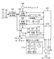
本発明は、例えば、図1に示すようなビデオカメラ100に適用される。
本実施の形態のビデオカメラ100は、それぞれ一連の動画像に対応した複数の動画像データをディスク108から再生するにあたり、特に、EVF110又は液晶パネル112に対して、複数の動画像データの代表画像を同一画面上に表示すると共に、ユーザから操作スイッチ群115の操作により指定された再生対象の動画像データの再生開始位置に関する情報を、当該動画像データの代表画像の近傍に表示し、上記再生開始位置に基づき動画像の再生を行なうように構成されている。これにより、動画像再生の際に、当該動画像の任意の位置(フレーム)からも容易に再生することができる。
以下、本実施の形態のビデオカメラ100の構成及び動作について具体的に説明する。
【0030】
<ビデオカメラ100の構成>
まず、図2は、上記図1に示した内部構成を有するビデオカメラ100の外観を示したものである。
【0031】
上記図2において、201は、ビデオカメラ本体である。
ビデオカメラ本体201内部には、詳細は後述するが、ハードディスクや光磁気ディスク等の記録媒体に対して、例えば、MPEG(Moving Picture Experts Group)方式等の圧縮処理により得られるMPEGデータの記録及び再生処理を施すための構成を有する。
【0032】
202はレンズ部であるり、203はマイクである。マイク203は、撮影時の音声をビデオカメラ本体201内部に入力するために設けられている。
【0033】
204は電子式ビューファインダ(EVF)である。
EVF204は、これをユーザが覗き込むことで、撮影時に被写体を狙う或いは確認するために設けられている。また、EVF204は、ビデオカメラ本体201内部に設けられた詳細は後述する制御機能によりON/OFFが制御される。
【0034】
205はトリガースイッチである。
トリガースイッチ205は、プッシュボタンからなり、これをユーザが操作することで、ユーザの撮影開始又は終了の意思をビデオカメラ本体201内部に伝達するために設けられている。また、基本的には、ビデオカメラ本体201内部は、詳細は後述するが、トリガースイッチ205により指示された撮影開始から終了までを、一つのファイルとして名称を付与して記録すると共に、同時に再生時に必要となる情報も記録されるように構成されている。このような記録情報により、早送り等の特殊再生や各種表示が実現できる。
【0035】
206はモードダイアルである。
モードダイヤル206は、例えば、上記図2に示すように(図中右側のモードダイヤル206の正面の拡大図参照)、再生モードに設定する機能を示す「再生」、カメラモードに設定する機能を示す「カメラ」、及びOFFにする機能を示す「OFF」が表記された回転式のスイッチである。また、モードダイヤル206の近傍のビデオカメラ本体201上には、バー212が表記されている。
【0036】
したがって、ユーザは、モードダイアル206を回転させ、「再生」、「カメラ」、及び「OFF」のうちの所望するモードの表記をバー212の位置に合わせることで、所望するモードでビデオカメラ本体201内部を起動させることができる。例えば、再生モードでは、カメラ機能がOFF状態となり、記録データの再生が行なわれ、必要に応じて、データ編集やデータ削除等の機能をも実施可能となる。一方、カメラモードでは、撮影を主目的としたモードで起動することになる。
【0037】
207は操作スイッチ群である。
操作スイッチ群207は、ユーザがビデオカメラ本体201を操作するための、特に、再生系やメニュー操作等のためのキーが配置されたものである。
【0038】
208は液晶パネルである。
液晶パネル208は、ビデオカメラ本体201の側面に対して開閉自在となるように、また、開いている状態で水平方向にも回転可能なように取り付けられている。また、液晶パネル208は、EVF204と同様に、撮影時には被写体像の確認、再生時には再生画像の表示を主に行うように構成されている。さらに、液晶パネル208は、EVF204と同様に、ビデオカメラ本体201内部の制御機能により、ON/OFFが制御される。
【0039】
211は、液晶パネル208が閉じている状態を電気的に検出するためのパネル開閉検出スイッチである。
例えば、液晶パネル208のフレームに突起が設けられており、当該突起部分により、液晶パネル208が閉じた状態ではパネル開閉検出スイッチ211が押される構造になっている。したがって、ビデオカメラ本体201内部の制御機能は、パネル開閉検出スイッチ211が押され状態と、放された状態との2つの状態を認識可能となる。
【0040】
209は、スピーカーであり、再生時に音声を出力するために設けられている。210は、バッテリーであり、ビデオカメラ本体201と着脱可能に設けられている。
【0041】
つぎに、上記図1を用いて、上記図2に示したビデオカメラ本体201(ビデオカメラ100)の内部構成について説明する。
【0042】
ビデオカメラ100は、上記図1に示すように、上記図2に示したレンズ部202に相当するレンズユニット101、CCD(charge coupled device)102、カメラ信号処理部103、上記図2に示したマイク203に相当するマイクユニット104、圧縮処理部105、ディスク制御部106、マイクロコンピュータ107、ディスク108、伸張処理部109、上記図2に示したEVF204に相当するEVF110、ミキサー111、上記図2に示した液晶パネル208に相当する液晶パネル112、上記図2に示したパネル開閉検出スイッチ211に相当するパネル開閉検出スイッチ113、上記図2に示したスピーカ209に相当するスピーカーユニット114、上記図2に示した操作スイッチ群207に相当する操作スイッチ群115、上記図2に示したモードダイアル206に相当するモードダイアル116、及び上記図2に示したトリガースイッチ205に相当するトリガースイッチ117を含む構成としている。
【0043】
マイクロコンピュータ107は、ビデオカメラ100全体の動作制御を司るものであり、このマイクロコンピュータ107の制御により、ここで説明するようなビデオカメラ100の機能が実施される。
【0044】
レンズユニット101は、例えば、集光のための固定レンズ群、変倍レンズ群、及び絞りと共に、変倍レンズ群の動きで移動した結像位置を補正する機能、及び焦点調節を行う機能を兼ね備えた補正レンズ群を含む構成としている。
このような構成のレンズユニット101により、最終的にCCD(撮像センサ)の結像面上に被写体像が結像される。
【0045】
CCD102は、レンズユニット101からの被写体光を電荷に変換することで、当該被写体の撮像信号を生成して出力する。
カメラ信号処理部103は、CCD102からの撮像信号に対して所定の処理を施すことで、ディジタル画像データを生成して出力する。
【0046】
マイクユニット104は、撮影時に音声を収集するために設けられており、所定の増幅、帯域制限、及びAD変換器等の構成を含み、当該構成によりディジタル音声データを生成して出力する。
【0047】
圧縮処理部105は、カメラ信号処理部103で得られたディジタル画像データ、及びマイクユニット104で得られたディジタル音声データに対して、例えば、MPEG(Moving Picture Experts Group)方式等の圧縮処理をリアルタイムに施すことで、圧縮ビデオデータを生成して出力する。
【0048】
ディスク108としては、例えば、光磁気ディスクのような書換可能な記録媒体を適用可能である。
ディスク制御部106は、ディスク108に対する、データの書込/読出の制御を行う。このとき、ディスク制御部106は、例えば、DOSファイルシステム等のパーソナルコンピュータ(パソコン)で用いられるフォーマットに従って、当該書込/読出制御を行なう。
【0049】
伸張処理部109は、ディスク制御部106を介してディスク108から読み出されたMPEGデータをビデオデータに変換して出力する。また、伸張処理部109は、当該MPEGデータから得られた伸張後の画像データを、任意の大きさの画像のデータに縮小或いは拡大して出力可能な機能を有する。
【0050】
ミキサ111は、マイクロコンピュータ107の制御により、カメラ信号処理部103で得られたディジタル画像データと、伸張処理部109で得られた画像データ(再生画像データ)とのうち一方の画像データを選択して出力し、また、必要に応じて、情報やビットマップ等を重ね合わせて出力する機能を有する。また、ミキサ111は、それぞれを独立して制御可能な2チャンネル(ch)の出力段を有する。
【0051】
EVF110及び液晶パネル112はそれぞれ、ミキサ111の出力データを受けて表示出力する。また、EVF110及び液晶パネル112はそれぞれ、その電源が独立しており、マイクロコンピュータ107の制御により、ビデオカメラ100本体とは独立してON/OFFすることが可能に構成されている。
【0052】
パネル開閉検出スイッチ113は、液晶パネル112の開閉状態を検出し、当該検出結果をマイクロコンピュータ107に対して通知する。
スピーカーユニット114は、ディスク108に記録されたMPEGデータの再生時において、伸張処理部109で得られた音声データを音声として出力する。また、スピーカーユニット114から出力される音声のボリュームは、マイクロコンピュータ107から制御可能である。
【0053】
操作スイッチ群115は、ユーザがビデオカメラ100を操作するために設けられたものであり、セットキー115_a、プラスキー115_b、マイナスキー115_c、修正キー115_d、及び再生キー115_eを含んでいる。
セットキー115_aは、メニュー等で選択した項目を決定し、当該項目に対応する動作を行なわせるため等に、ユーザから操作(押下)されるキーである。プラスキー115_b及びマイナスキー115_cは、メニューの複数の項目等の中から1つを選択するために、ユーザから操作(押下)されるキーである。
【0054】
尚、操作スイッチ群115には、上記図1に示したキー115_a〜115_eに限られることはなく、その他の任意の処理を実行させるためのキーが含まれるものとしてもよい。
【0055】
モードダイアル116は、「再生」モード、「カメラ」モード、及び「OFF」を選択するためのスイッチである。
トリガースイッチ117は、モードダイアル116により「カメラ」モードが選択設定された場合に、ユーザからの操作(トリガースイッチ117の押下)に基づいて、撮影開始ポイント及び撮影終了ポイントのイベントを発生させる。
【0056】
尚、モードダイアル116及びトリガースイッチ117は、操作スイッチ群115と同様にユーザから操作されるものであるが、上記図2を用いた説明で独立させたので同様にした。
【0057】
<ビデオカメラ100の動作>
ここでは、ビデオカメラ100の特徴とする動作である、「再生」モード時の動作について説明する。
【0058】
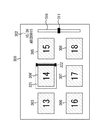
図3は、マイクロコンピュータ107の制御により、EVF110又は液晶パネル112で表示される、ビデオクリップ(動画像)の再生選択画面300(GUI)の一例を示したものである。
【0059】
尚、ビデオカメラ100に対して、例えば、テレビモニタに対してデータ出力するためのビデオ出力端子や、PCや、ディジタルテレビ、或いはビデオデッキ等と接続するためのIEEE1394端子やUSBが搭載されている場合、その接続先の機器にも再生選択画面300が表示されるようにしてもよい。
【0060】
再生選択画面300は、上記図3に示すように、ビデオクリップの代表画像表示領域303〜308、スライダ310、ポインタ311、及びビデオクリップ情報表示領域302と共に、特に、選択枠321及びインジケータ322を含む構成としている。
【0061】
尚、代表画像表示領域303〜308、スライダ310、ポインタ311、及びビデオクリップ情報表示領域302については、上記図12に示した代表画像表示領域1503〜1508、スライダ1510、ポインタ1511、及びビデオクリップ情報表示領域1502と同様の機能を有するため、ここでは、これらの詳細な説明は省略し、本実施の形態の特徴とする構成及び動作について具体的に説明する。
【0062】
選択枠321は、代表画像表示領域303〜308に表示されてる代表画像により、現在選択されているビデオクリップをユーザに知らしめるために表示されるものである。
【0063】
インジケータ322は、現在再生命令が発生した時に開始する位置を示すものである。
すなわち、インジケータ322は、選択枠321で現在選択されているビデオクリップにおいて、先頭位置を左端、最後尾位置を右端とし、選択枠321の範囲を移動するものである。
【0064】
上記図3では、一例として、選択枠321により、代表画像表示領域305で表示されている代表画像に対応するビデオクリップが選択されており、さらに、インジケータ322により、再生命令が発生した時には当該ビデオクリップの最後尾から再生開始することが示されている。
【0065】
本実施の形態では、選択枠321及びインジケータ322の動作(表示の動き)の構成を特徴としており、以下に説明するような選択枠321及びインジケータ322の動作は、マイクロコンピュータ107の制御により実施される。
【0066】
具体的には、まず、図4(a)は、現在、代表画像表示領域305で表示されている代表画像に対応するビデオクリップが選択された状態を示している。このとき、インジケータ322は、選択枠321内の右端(選択ビデオクリップの最後尾位置)に位置している。
【0067】
ユーザは、マイナスキー115_cを操作(押下)すると、この操作を認識したマイクロコンピュータ107の制御により、上記図4(b)に示すように、選択枠321内において、インジケータ322が左方向へと移動する。
【0068】
ユーザは、さらのマイナスキー115_cを操作(押下)し続けると、この操作を認識したマイクロコンピュータ107の制御により、上記図4(c)に示すように、選択枠321内において、インジケータ322が左端へと移動する。
【0069】
上述のようなインジケータ322の動作は、例えば、実際には記録媒体はディスク108であるが、ユーザにとっては記録媒体がビデオテープであり、これを巻き上げるかのようにイメージされる。
【0070】
インジケータ322が、上記図4(c)に示したように左端まで移動した後、すなわちユーザに対してビデオクリップの先頭まで巻き上げたイメージが表示された後、図5に示すように、選択枠321及びインジケータ322は、代表画像表示領域305から代表画像表示領域304へと移動し、この状態で、インジケータ322は、上記図4(a)〜(c)を用いて説明したような動作が実施可能となる。
【0071】
上述のようにして、マイクロコンピュータ107の制御により、選択枠321が、先頭のビデオクリップの代表画像が表示された代表画像表示領域(ここでは代表画像表示領域303)まで移動し、さらにインジケータ322が、当該代表画像表示領域の左端まで移動すると(そのビデオクリップの先頭まで巻き戻したイメージ)、選択枠321及びインジケータ322の動作が終了する。
【0072】
或いは、動作中にユーザが再生キー115_eを押下すると、マイクロコンピュータ107の制御により、選択枠321及びインジケータ322の動作が終了し、その時点で選択枠321が存在する代表画像表示領域に対応するビデオクリップが、その時点でインジケータ322により示される位置からの再生が開始される。
【0073】
例えば、代表画像表示領域305に対応するビデオクリップの全長10分であり、上記図4(b)に示したインジケータ322の状態の時に、ユーザから再生キー115_eが押下されたとする。また、上記図4(b)のインジケータ322の位置は、当該ビデオクリップの全長の7割に相当する位置であるとする。この場合、当該ビデオクリップの先頭から7分の位置から再生が開始される。
【0074】
このときのインジケータ322の移動速度は、例えば、
所定値÷選択枠321が指し示すビデオクリップの長さ(通常再生時間)で表せ、ビデオデッキ等で一般的に表現される所謂N倍速に相当する。
【0075】
尚、上記所定値は、インジケータ322の移動速度を決定する値であるが、例えば、上記所定値を複数段階設け、メニュー等によってユーザが任意に選択可能とする、或いは状況によって可変するように構成してもよい。
【0076】
また、ユーザがプラスキー115_bを押下すると、マイクロコンピュータ107の制御により、それまでの早送り方向にインジケータ322の移動動作が、最後のビデオクリップの終端まで、或いはユーザから再生開始の指示がなされるまで続けられる。
【0077】
したがって、従来では、上記図12を用いて説明したように、ビデオクリップの中途からダイレクトに再生を開始するような操作ができなかったが、本実施の形態によれば、この操作が可能となる。また、ユーザに対する表示及び操作が、従来多く用いられていたテープ記録媒体(ビデオテープ等)のビデオデッキ等に近く、違和感がなく親しみ易い。
【0078】
[第2の実施の形態]
まず、例えば、本発明を適用可能なビデオカメラとしては、静止画撮影機能を搭載したものが挙げられる。
【0079】
ビデオテープを記録媒体としたビデオカメラでは、静止画撮影により取得した画像をビデオテープに記録する場合、例えば、6秒間等の所定時間の繰り返し記録を行なう。
これに対して、メモリーカードやディスクを記録媒体としたビデオカメラの場合、静止画撮影により取得した画像を、JPEG(Joint Photographic Coding Experts Group)方式等で圧縮し、当該圧縮画像を静止画ファイルとして記録媒体に記録するのが一般的である。
【0080】
ここで、第1の実施の形態では、代表画像群を用いた再生選択画面300(上記図3参照)では、動画像を選択対象としたが、静止画や、静止画と動画を混在させたものから選択可能とするようにしてもよい。しかしながら、第1の実施の形態では、インジケータ322の移動速度を通常再生時間に依存して決定するように構成したので、インジケータ322が動画像の代表画像表示領域に移動した場合には問題ないが、静止画像の代表画像表示領域に移動した場合、当該代表画像表示領域をスキップして次の代表画像表示領域に移動する、或いはそのまま停止してしまう可能性がある。
【0081】
そこで、本実施の形態では、再生選択画面300において、選択対象とする画像が動画と静止画で混在する場合、上記の問題を解決するために、以下に説明するような構成及び動作とする。
【0082】
<本実施の形態におけるビデオカメラ100の構成>
例えば、図6に示すように、本実施の形態におけるビデオカメラ100は、上記図1に示した構成に加えて、静止画記録トリガー420を更に設けた構成としている。
【0083】
静止画記録トリガー420が、モードダイヤル116によりカメラモードが設定されているときに、ユーザから操作(押下)されると、静止画撮影が実行される。
【0084】
静止画記録トリガー420は、押下状態でない第一の位置、浅く押下された状態の第二の位置、及び深く押下された状態の第三の位置を、マイクロコンピュータ107により検出可能な構成としている。
【0085】
例えば、マイクロコンピュータ107は、静止画記録トリガー420の第二の位置を検出すると、露出やオートフォーカスによるピント等を決定し、静止画記録トリガー420の第三の位置を検出すると、撮影画像を静止画像として記録するための動作制御を行なう。
【0086】
このため、圧縮処理部105は、第1の実施の形態における機能と同様な機能の他、静止画像を、例えば、JPEG方式等により圧縮し、当該圧縮静止画像データを出力する機能を有する。
また、伸張処理部109は、第1の実施の形態における機能と同様な機能の他、圧縮静止画像データを伸張して元の静止画像データを復元し、これを出力する機能を有する。
【0087】
<本実施の形態におけるビデオカメラ100の動作>
ここでは、本実施の形態におけるビデオカメラ100の特徴とする動作である、「再生」モード時の動作について説明する。
【0088】
図7は、マイクロコンピュータ107の制御により、EVF110又は液晶パネル112で表示される、本実施の形態における再生選択画面300の一例を示したものである。
【0089】
上記図7の再生選択画面300は、第1の実施の形態における再生選択画面300(上記図3等参照)の構成及び動作と基本的には同様のものであるが、代表画像表示領域304´に関して、静止画撮影により得られた静止画像の縮小画像が代表画像として表示されている。
【0090】
すなわち、本実施の形態における再生選択画面300の代表画像表示領域303〜308には、動画(ビデオクリップ)の代表画像と、静止画の代表画像とが混在して表示されており、ユーザは、再生画像を、動画と静止画で任意に選択可能である。
【0091】
また、本実施の形態における再生選択画面300においても、選択枠321が設けられており、例えば、ユーザがマイナスキー115_cを押下すると、マイクロコンピュータ107の制御により、第1の実施の形態で説明したように、インジケータ322が左方向へと移動する。
【0092】
特に、本実施の形態では、選択枠321が次の代表画像の代表画像表示領域へと移動するときに、マイクロコンピュータ107は、当該代表画像表示領域に表示されている代表画像が、動画像のものであるか、静止画像のものであるかを判断する。
【0093】
上記の判断の結果、静止画像である場合、マイクロコンピュータ107は、予め保持している、インジケータ322の移動速度を所定速度とするための静止画時インジケータ移動速度データに基づき、インジケータ322を移動させる。
【0094】
尚、上記の静止画時インジケータ移動速度データは、例えば、初期値の他に、メニュー等でユーザが任意に設定可能にしてもよい。
【0095】
また、選択枠411が静止画像に対応する代表画像表示領域304´に位置している状態で、ユーザが再生キー115_eを押下すると、マイクロコンピュータ107は、当該静止画像を画面全体に再生表示させる。
【0096】
また、ユーザがマイナスキー115_cではなくプラスキー115_bを押下すると、マイクロコンピュータ107は、第1の実施の形態と同様にして逆方向の移動制御を行なう。
【0097】
図8は、上述したようなマイクロコンピュータ107による動作制御をフローチャートにより示したものである。
例えば上記図7に示したような状態の再生選択画面300において、ユーザからマイナスキー115_c又はプラスキー115_bが押下されると、以下に説明する動作が開始される。
【0098】
尚、便宜上トリガーがマイナスキー115_cの場合を巻き戻し、プラスキー115_bの場合を早送りと呼ぶことにする。
【0099】
ステップS502:
マイクロコンピュータ107は、初期化処理を実行する。
例えば、マイクロコンピュータ107は、選択枠322により現在ビデオクリップが選択されている場合、インジケータ321を当該ビデオクリップの代表画像表示領域の現在相当位置にセットし、選択枠321により現在静止画が選択されている場合、インジケータ322を当該静止画の代表画像表示領域の始端にセットする。
ここでの「始端」とは、巻き戻しでは選択枠322の右端、早送りでは左端のことを示す。後述する「終端」はこの逆である。
【0100】
ステップS503:
マイクロコンピュータ107は、インジケータ322が終端であるか否かを判別する。例えば、マイクロコンピュータ107は、送る方向と現在のインジケータ322の位置から、当該判別を行なう。
この判別の結果、インジケータ322が終端である場合にはステップS508に進み、そうでない場合にはステップS504に進む。
【0101】
ステップS504:
インジケータ322が終端でない場合、マイクロコンピュータ107は、現在選択枠321が存在する代表画像表示領域の代表画像が指し示す画像が静止画像であるか、或いはビデオクリップであるかを判別する。
この判別の結果、静止画像である場合にはステップS505に進み、ビデオクリップである場合にはステップS506に進む。
【0102】
ステップS505:
現在選択枠321が存在する代表画像表示領域の代表画像が指し示す画像が静止画像である場合、マイクロコンピュータ107は、所定値Data1の分だけ、インジケータ322の表示位置を送り方向に移動する。
ここでの所定値Data1とは、予めマイクロコンピュータ107内のROM等に記憶されているデータである。
その後、ステップS507に進む。
【0103】
ステップS506:
現在選択枠321が存在する代表画像表示領域の代表画像が指し示す画像がビデオクリップである場合、マイクロコンピュータ107は、(所定値Data2÷現在選択されているビデオクリップの記録時間)の分だけ、インジケータ322の表示位置を送り方向に移動する。
ここでの所定値Data2とは、予めマイクロコンピュータ107内のROM等に記憶されているデータである。
その後、ステップS507に進む。
【0104】
ステップS507:
マイクロコンピュータ107は、所定時間を意味するconst1の分だけ停止する。
具体的には例えば、ここでの処理は、マイクロコンピュータ107でリアルタイムOS等を用いている場合、本処理を実行するタスクを待ち状態に遷移させることを意味するものであり、マイクロコンピュータ107を停止させるものではない。
その後、再びステップS503へと戻り、ステップS503〜ステップS507の処理は、ステップS503でインジケータ322が終端であると判別されるまで繰り返し実行される。
【0105】
ステップS508:
ステップS503の判別の結果、インジケータ322が終端である場合、マイクロコンピュータ107は、選択枠321を次の代表画像表示領域へと移動させるにあたり、当該代表画像表示領域が存在するか否か(次の画像が存在するか否か)を判別する。
この判別の結果、次の画像が存在する場合にはステップS510に進み、そうでない場合、すなわち送り方向の最後の画像まで達している場合、表示や内部フラグ等必要な処理の実行後、本処理終了となる。
【0106】
ステップS510:
次の画像が存在する場合、マイクロコンピュータ107は、インジケータ322を始端にセット(表示)する。
静止画像の場合の始端とは、巻き戻しでは選択枠321の右端に、早送りでは左端を意味する。
その後、再びステップS503へと戻る。
【0107】
尚、上記図8に示した一連の処理は、上述の通り、再生キー115_eが押された時点で終了する。
【0108】
上述したような本実施の形態によれば、第1の実施の形態で得られる効果に加え、静止画像とビデオクリップが混在する場合であっても有効に作用する。
【0109】
[第3の実施の形態]
第1及び第2の実施の形態では、ディスク108の再生時の動作(テープ状記録媒体の早送り/巻き戻し動作に対応する動作)において、再生選択画面300の選択枠321とインジケータ322の動作に特徴を持たせたが、本実施の形態では、さらに複数枚配列された代表画像をも変化させる。
【0110】
具体的には、図9は、マイクロコンピュータ107の制御により、EVF110又は液晶パネル112で表示される、本実施の形態における再生選択画面600の一例を示したものである。
【0111】
尚、上記図9の再生選択画面600において、上記図3等に示した再生選択画面300と同様に機能する箇所には同じ符号を付し、その詳細な説明は省略する。
【0112】
代表画像表示領域603、604、及び606〜608は、ビデオクリップを構成するフレームの中から1フレームを選択し、これを縮小した縮小画像が代表画像として表示される領域である。
特に、代表画像表示領域603及び604には、該当するビデオクリップを構成するフレームの最後のフレームを縮小したものが代表画像として表示される。一方、代表画像表示領域606〜608には、該当するビデオクリップを構成するフレームの先頭のフレームを縮小したものが代表画像として表示される。
また、代表画像表示領域605には、静止画像の代表画像(縮小画像)が表示される。
【0113】
上記図9では、選択枠321により、代表画像表示領域604のビデオクリップが選択され、さらにユーザ操作により再生命令が発生した場合、当該ビデオクリップの最後尾から再生開始することを示している。
【0114】
本実施の形態の特徴とする構成は、マイクロコンピュータ107の制御により、ビデオクリップの代表画像が変化していくところにあり、これに関しては図10(a)〜(c)を用いて説明する。
【0115】
まず、上記図10(a)は、現在、代表画像表示領域604で表示されている代表画像(最後のフレーム604(E))に対応するビデオクリップが選択された状態を示している。このとき、インジケータ322は、選択枠321内の右端(選択ビデオクリップの最後尾位置)に位置している。
【0116】
ユーザは、マイナスキー115_cを操作(押下)すると、この操作を認識したマイクロコンピュータ107の制御により、上記図10(b)に示すように、選択枠321内において、インジケータ322が左方向へと移動する。
【0117】
このとき、マイクロコンピュータ107の制御により、インジケータ322の移動に伴って、代表画像表示領域604の表示が、代表画像(最後のフレーム604(E))から代表画像(最後のフレームから先に戻ったフレーム604(M))へと変化する。すなわち、画像表示(フレーム表示)そのものが、テープ状記録媒体の巻き戻しのように変化していく。
ここでの変化間隔は、例えば、予め決定された間隔としているが、画像が大きく変化する度に変化させるようにしてもよい。
【0118】
ユーザは、さらのマイナスキー115_cを操作(押下)し続けると、この操作を認識したマイクロコンピュータ107の制御により、上記図10(c)に示すように、選択枠321内において、インジケータ322が左端へと移動する。
【0119】
このときにおいても、マイクロコンピュータ107の制御により、インジケータ322の移動に伴って、代表画像表示領域604の表示が、代表画像(フレーム604(M))から代表画像(先頭のフレーム604(T))へと変化する。
【0120】
上述のように本実施の形態では、選択枠321が存在する画像より前(巻き戻し方向)のビデオクリップの代表画像表示領域には、当該ビデオクリップの最後のフレームを縮小したものを表示し、選択枠321が存在する画像より後(早送り方向)にあるビデオクリップの代表画像表示領域には、当該ビデオクリップの先頭のフレームを縮小したものを表示する。また、選択枠321が存在する画像がビデオクリップである場合、当該ビデオクリップの代表画像表示領域には、インジケータ322の位置に応じたフレームの縮小画像を表示する。
【0121】
尚、静止画については第2の実施の形態と同様であるため、その詳細な説明は省略する。
【0122】
したがって、本実施の形態によれば、第1及び第2の実施の形態で得られる効果に加え、再生選択画面600において、ビデオクリップの縮小画像が変化するため、ユーザは所望する再生開始のポイントを見つけやすくなる。
【0123】
尚、本発明の目的は、第1〜第3の実施の形態のホスト及び端末の機能を実現するソフトウェアのプログラムコードを記憶した記憶媒体を、システム或いは装置に供給し、そのシステム或いは装置のコンピュータ(又はCPUやMPU)が記憶媒体に格納されたプログラムコードを読みだして実行することによっても、達成されることは言うまでもない。
この場合、記憶媒体から読み出されたプログラムコード自体が第1〜第3の実施の形態の機能を実現することとなり、そのプログラムコードを記憶した記憶媒体及び当該プログラムコードは本発明を構成することとなる。
プログラムコードを供給するための記憶媒体としては、ROM、フレキシブルディスク、ハードディスク、光ディスク、光磁気ディスク、CD−ROM、CD−R、磁気テープ、不揮発性のメモリカード等を用いることができる。
また、コンピュータが読みだしたプログラムコードを実行することにより、第1〜第3の実施の形態の機能が実現されるだけでなく、そのプログラムコードの指示に基づき、コンピュータ上で稼動しているOS等が実際の処理の一部又は全部を行い、その処理によって第1〜第3の実施の形態の機能が実現される場合も含まれることは言うまでもない。
さらに、記憶媒体から読み出されたプログラムコードが、コンピュータに挿入された拡張機能ボードやコンピュータに接続された機能拡張ユニットに備わるメモリに書き込まれた後、そのプログラムコードの指示に基づき、その機能拡張ボードや機能拡張ユニットに備わるCPUなどが実際の処理の一部又は全部を行い、その処理によって第1〜第3の実施の形態の機能が実現される場合も含まれることは言うまでもない。
【0124】
図11は、上記コンピュータの機能800を示したものである。
コンピュータ機能800は、上記図11に示すように、CPU801と、ROM802と、RAM803と、キーボード(KB)809のキーボードコントローラ(KBC)805と、表示部としてのCRTディスプレイ(CRT)810のCRTコントローラ(CRTC)806と、ハードディスク(HD)811及びフレキシブルディスク(FD)812のディスクコントローラ(DKC)807と、ネットワーク820との接続のためのネットワークインターフェースコントローラ(NIC)808とが、システムバス804を介して互いに通信可能に接続された構成としている。
【0125】
CPU801は、ROM802或いはHD811に記憶されたソフトウェア、或いはFD812より供給されるソフトウェアを実行することで、システムバス804に接続された各構成部を総括的に制御する。
すなわち、CPU801は、所定の処理シーケンスに従った処理プログラムを、ROM802、或いはHD811、或いはFD812から読み出して実行することで、第1〜第3の実施の形態での動作を実現するための制御を行う。
【0126】
RAM803は、CPU801の主メモリ或いはワークエリア等として機能する。
KBC805は、KB809や図示していないポインティングデバイス等からの指示入力を制御する。
CRTC806は、CRT810の表示を制御する。
DKC807は、ブートプログラム、種々のアプリケーション、編集ファイル、ユーザファイル、ネットワーク管理プログラム、及び第1〜第3の実施の形態における所定の処理プログラム等を記憶するHD811及びFD812とのアクセスを制御する。
NIC808は、ネットワーク820上の装置或いはシステムと双方向にデータをやりとりする。
【0127】
【発明の効果】
以上説明したように本発明によれば、動画像を含む複数の画像を記録媒体から再生するにあたり、複数の画像の代表画像(動画像の場合には当該動画像を構成する一連のフレームの中の任意のフレームの縮小画像等)を同一画面上に表示すると共に、これらの代表画像により再生対象画像として選択された画像(再生対象画像)の代表画像に関わる所定位置(代表画像の近傍位置等)に対して、再生対象画像の再生動作に基づき、再生対象画像を再生開始位置を示す情報を表示するように構成した。
【0128】
このような構成により、代表画像を複数枚表示して再生画像を選択させるGUI等において、動画像(ビデオクリップ)を再生する場合、当該動画像の中途からダイレクトに再生を開始するような操作が可能となる。また、記録媒体が、例えば、ディスク状記録媒体であったとしても、ユーザに対して、動画像の再生開始位置を、テープ状記録媒体を巻き上げるかのようにイメージして表示することができるので、テープ状記録媒体に慣れているユーザにとって感覚的に親しみ易くなる。
【図面の簡単な説明】
【図1】第1の実施の形態において、本発明を適用したビデオカメラの構成を示すブロック図である。
【図2】上記ビデオカメラの外観図である。
【図3】上記ビデオカメラで表示される、ビデオクリップ(動画像)の再生選択画面(インデックス画面)の一例を説明するための図である。
【図4】上記再生選択画面において、選択枠及びインジケータの動作を説明するための図である。
【図5】上記再生選択画面において、上記選択枠及びインジケータが次のビデオクリップに移動した状態を説明するための図である。
【図6】第2の実施の形態において、本発明を適用したビデオカメラの構成を示すブロック図である。
【図7】上記ビデオカメラで表示される、ビデオクリップ(動画像)又は静止画の再生選択画面(インデックス画面)の一例を説明するための図である。
【図8】上記ビデオカメラの動作を説明するための図である。
【図9】第3の実施の形態における上記再生選択画面(インデックス画面)の一例を説明するための図である。
【図10】上記再生選択画面において、選択枠及びインジケータの動作を説明するための図である。
【図11】上記ビデオカメラの機能をコンピュータに実現させるためのプログラムをコンピュータ読出可能な記憶媒体から読み出して実行する当該コンピュータの構成を示すブロック図である。
【図12】従来の再生選択画面を説明するための図である。
【符号の説明】
100 ビデオカメラ
101 レンズユニット
102 CCD
103 カメラ信号処理部
104 マイクユニット
105 圧縮処理部
106 ディスク制御部
107 マイクロコンピュータ
108 ディスク
109 伸張処理部
110 電子式ビューファインダー(EVF)
111 ミキサ
112 液晶パネル
113 パネル開閉検出スイッチ
114 スピーカーユニット
115 操作スイッチ群
116 モードダイアル
117 トリガースイッチ
201 ビデオカメラ本体
202 レンズ部
203 マイク
204 電子式ビューファインダー(EVF)
205 トリガースイッチ
206 モードダイアル
207 操作スイッチ群
208 液晶パネル
209 スピーカ
210 バッテリ
211 パネル開閉検出スイッチ
212 バー
301 再生選択画面
302 ビデオクリップ情報表示領域
303〜308 代表画像表示領域
309 カーソル
310 スライダー
311 ポインター(スライダーの一部)
321 選択枠
322 インジケータ[0001]
BACKGROUND OF THE INVENTION
The present invention is an image processing apparatus suitable for use in a digital video camera or the like that uses a randomly accessible medium such as a magneto-optical disk, hard disk, or memory card as a recording medium and reproduces image data from the recording medium. The present invention relates to an image processing method, a program, and a recording medium.
[0002]
[Prior art]
Conventionally, for example, a digital video camera using a randomly accessible recording medium such as a magneto-optical disk, a hard disk, or a memory card has a display unit such as an electronic viewfinder (hereinafter referred to as “EVF”) or a liquid crystal panel. In addition, an output terminal is provided for outputting data to a device such as a television device (TV monitor) or a personal computer (PC).
[0003]
The display unit displays a subject image (moving image or the like) at the time of shooting, a playback image at the time of playback, and information necessary for various settings and selections.
As the output terminal, an IEEE1394 terminal, a USB terminal, or the like is used, which allows the digital video camera to be connected to various devices such as a digital television apparatus and a video deck in addition to a TV monitor and a PC.
[0004]
FIG. 12 shows an example of an
[0005]
The
[0006]
The
[0007]
The representative images displayed in the representative
[0008]
A
In FIG. 12, a video clip indicated by the representative
[0009]
The
[0010]
In the video clip
In FIG. 12, as an example, video clip information “15/30” and “ABCD0015” are displayed in the video clip
[0011]
For example, in the above state, when the user performs an operation for executing playback, playback of the video clip selected by the cursor 1509 (the video clip indicated by the representative image display area 1505) is started. . When the reproduction is completed, the
[0012]
Alternatively, the video clips are sequentially played back until the user performs an operation for stopping playback, and when the playback is finished up to the last video clip, the
[0013]
Note that the
[0014]
The user interface such as the
The difference between the user interface of a digital video camera that handles moving images and the user interface of a digital camera that handles still images is that the selection target image is a still image or one of the frames that make up a moving image. Is it an image?
[0015]
By the way, a video tape is often used as a moving image recording medium, and a video deck and a video camera are examples of the recording / reproducing apparatus.
[0016]
As a matter of course, the videotape cannot be randomly accessed, and when it is desired to reproduce a moving image before and after the current position, operations such as rewinding and fast-forwarding are required, and a corresponding time is required.
[0017]
Further, the main body of the recording / reproducing apparatus using the video tape is provided with a display unit for displaying, for example, a bar indicating the current reproduction position, a remaining amount, a counter, and the like. The playback position of the tape can be recognized.
[0018]
[Problems to be solved by the invention]
However, in the conventional digital video camera using the randomly accessible recording medium as described above, the configuration for display and operation when selecting a moving image (video clip) to be reproduced is as follows. There was a problem.
[0019]
For example, in the
[0020]
Also, users who are accustomed to video tape-based devices, rather than devices using random-accessible recording media, may feel uncomfortable or sensuous to operate devices using random-accessible recording media. There is a possibility that the concept of time will fade.
[0021]
Therefore, the present invention is made to eliminate the above-described drawbacks, and is an image processing device that can be easily reproduced from an arbitrary position (frame) of the moving image when the moving image is reproduced. An object is to provide an image processing method, a program, and a recording medium.
[0022]
[Means for Solving the Problems]
The image processing apparatus of the present invention is an apparatus for reproducing a plurality of moving image data each representing a moving image from a recording medium, and a reproduction start position of the moving image data to be reproduced selected from the plurality of moving image data And a plurality of representative images indicating the plurality of moving image data are displayed on the same screen, and a predetermined position related to the representative image of the selected moving image data is displayed. Display means for displaying an indicator indicating the reproduction start position designated by the reproduction start position designation means in the selected moving image data; and the selection from the reproduction start position designated by the reproduction start position designation means Control means for controlling the reproduction operation of the moving image data so as to reproduce the moving image data.
[0023]
The image processing apparatus of the present invention is an apparatus for reproducing a plurality of moving image data each indicating a moving image from a recording medium, and displays a plurality of representative images indicating the plurality of moving image data on the same screen. And display means for displaying an indicator indicating a reproduction start position in the selected moving image data at a predetermined position related to a display position of a representative image of the selected moving image data to be reproduced among the plurality of moving image data. An instruction means for arbitrarily instructing movement of the indicator, and the display position of the indicator is moved within a predetermined display range with respect to the representative image of the selected moving image data in accordance with an instruction from the instruction means. Controlling the display means, determining a reproduction start position in the selected moving image data based on the display position of the indicator, Serial and a controlling means for controlling the reproducing operation of the moving image data to reproduce moving image data said selected reproduction start position.
[0024]
The image processing method of the present invention is a method for reproducing a plurality of moving image data each representing a moving image from a recording medium, and reproducing the selected moving image data to be reproduced among the plurality of moving image data. A reproduction start position designation step for arbitrarily designating a start position, and a plurality of representative images indicating the plurality of moving image data are displayed on the same screen, and at a predetermined position related to the representative image of the selected moving image data. On the other hand, the display step for displaying an indicator indicating the reproduction start position designated by the reproduction start position designation step in the selected moving image data, and the selection from the reproduction start position designated by the reproduction start position designation step. And a control step for controlling a reproduction operation of the moving image data so as to reproduce the moving image data.
[0025]
The image processing method of the present invention is a method for reproducing a plurality of moving image data each indicating a moving image from a recording medium, and displaying a plurality of representative images indicating the plurality of moving image data on the same screen. In addition, an indicator indicating a reproduction start position in the selected moving image data is displayed on a display unit at a predetermined position related to the display position of the representative image of the moving image data to be reproduced selected among the plurality of moving image data. A display step for indicating, an instruction step for arbitrarily instructing movement of the indicator, and a display position of the indicator within a predetermined display range with respect to the representative image of the selected moving image data in accordance with an instruction by the instruction step And controlling the display means so that the selected moving image data based on the display position of the indicator Determining the raw starting position, and a controlling step of controlling the reproducing operation of the moving image data to reproduce moving image data to which the selected from the playback start position.
[0026]
Moreover, the program of this invention is a program for making a computer perform each step of said image processing method.
[0027]
The recording medium of the present invention is a computer-readable recording medium recording a program for causing a computer to execute each step of the image processing method.
[0028]
DETAILED DESCRIPTION OF THE INVENTION
Hereinafter, embodiments of the present invention will be described with reference to the drawings.
[0029]
[First embodiment]
The present invention is applied to, for example, a
When the
Hereinafter, the configuration and operation of the
[0030]
<Configuration of
First, FIG. 2 shows an appearance of the
[0031]
In FIG. 2,
Although the details will be described later in the
[0032]
[0033]
The
[0034]
The
[0035]
The
[0036]
Therefore, the user rotates the
[0037]
The
[0038]
The
[0039]
For example, a protrusion is provided on the frame of the
[0040]
[0041]
Next, the internal configuration of the video camera main body 201 (video camera 100) shown in FIG. 2 will be described with reference to FIG.
[0042]
As shown in FIG. 1, the
[0043]
The
[0044]
The
By the
[0045]
The
The camera
[0046]
The
[0047]
The
[0048]
As the
The
[0049]
The
[0050]
The
[0051]
Each of the
[0052]
The panel open /
The
[0053]
The
The set key 115_a is a key operated (pressed) by the user in order to determine an item selected from a menu or the like and perform an operation corresponding to the item. The plus key 115_b and the minus key 115_c are keys operated (pressed) by the user in order to select one from a plurality of items on the menu.
[0054]
The
[0055]
The
When the “camera” mode is selected and set by the
[0056]
The
[0057]
<Operation of
Here, an operation in the “playback” mode, which is an operation characteristic of the
[0058]
FIG. 3 shows an example of a video clip (moving image) playback selection screen 300 (GUI) displayed on the
[0059]
The
[0060]
As shown in FIG. 3, the
[0061]
For the representative
[0062]
The
[0063]
The
That is, the
[0064]
In FIG. 3, as an example, a video clip corresponding to the representative image displayed in the representative
[0065]
The present embodiment is characterized by the configuration of the operation (display movement) of the
[0066]
Specifically, first, FIG. 4A shows a state where a video clip corresponding to the representative image currently displayed in the representative
[0067]
When the user operates (presses) the minus key 115_c, the control of the
[0068]
When the user continues to operate (presses) the further minus key 115_c, the control of the
[0069]
The operation of the
[0070]
After the
[0071]
As described above, under the control of the
[0072]
Alternatively, when the user presses the play key 115_e during the operation, the operation of the
[0073]
For example, it is assumed that the video clip corresponding to the representative
[0074]
The moving speed of the
It can be expressed by the predetermined value ÷ the length of the video clip indicated by the selection frame 321 (normal playback time), which corresponds to the so-called N-times speed generally expressed by a video deck or the like.
[0075]
The predetermined value is a value that determines the moving speed of the
[0076]
When the user presses the plus key 115_b, the
[0077]
Therefore, conventionally, as described with reference to FIG. 12, an operation for directly starting playback from the middle of a video clip could not be performed. However, according to the present embodiment, this operation can be performed. . In addition, the display and operation for the user is close to a video deck of a tape recording medium (video tape or the like) that has been widely used so far, and there is no sense of incongruity and it is easy to become familiar.
[0078]
[Second Embodiment]
First, for example, as a video camera to which the present invention can be applied, a camera equipped with a still image shooting function can be mentioned.
[0079]
In a video camera using a video tape as a recording medium, when an image acquired by still image shooting is recorded on the video tape, for example, recording is repeatedly performed for a predetermined time such as 6 seconds.
On the other hand, in the case of a video camera using a memory card or disc as a recording medium, an image acquired by still image shooting is compressed using a JPEG (Joint Photographic Coding Experts Group) method, and the compressed image is converted into a still image file. It is common to record on a recording medium.
[0080]
Here, in the first embodiment, on the
[0081]
Therefore, in the present embodiment, when the images to be selected are mixed in the moving image and the still image on the
[0082]
<Configuration of
For example, as shown in FIG. 6, the
[0083]
When the still
[0084]
The still
[0085]
For example, when the
[0086]
For this reason, the
In addition to the function similar to the function in the first embodiment, the
[0087]
<Operation of
Here, an operation in the “playback” mode, which is an operation characteristic of the
[0088]
FIG. 7 shows an example of the
[0089]
The
[0090]
That is, in the representative
[0091]
In addition, the
[0092]
In particular, in this embodiment, when the
[0093]
As a result of the above determination, if the image is a still image, the
[0094]
The above-described still image indicator movement speed data may be arbitrarily set by the user by using a menu or the like in addition to the initial value, for example.
[0095]
Further, when the user presses the reproduction key 115_e in a state where the selection frame 411 is positioned in the representative
[0096]
When the user presses down the plus key 115_b instead of the minus key 115_c, the
[0097]
FIG. 8 is a flowchart showing the operation control by the
For example, when the user presses the minus key 115_c or the plus key 115_b on the
[0098]
For convenience, the case where the trigger is the minus key 115_c is rewound, and the case where the trigger is the plus key 115_b is called fast-forward.
[0099]
Step S502:
The
For example, when the current video clip is selected in the
Here, the “starting end” indicates the right end of the
[0100]
Step S503:
The
If the result of this determination is that the
[0101]
Step S504:
If the
If it is determined that the image is a still image, the process proceeds to step S505. If the image is a video clip, the process proceeds to step S506.
[0102]
Step S505:
When the image pointed to by the representative image in the representative image display area where the
Here, the predetermined value Data1 is data stored in advance in a ROM or the like in the
Thereafter, the process proceeds to step S507.
[0103]
Step S506:
When the image pointed to by the representative image in the representative image display area in which the currently selected
Here, the predetermined value Data2 is data stored in advance in a ROM or the like in the
Thereafter, the process proceeds to step S507.
[0104]
Step S507:
The
Specifically, for example, when the
Thereafter, the process returns to step S503 again, and the processes in steps S503 to S507 are repeatedly executed until it is determined in step S503 that the
[0105]
Step S508:
If the result of determination in step S503 is that the
As a result of the determination, if the next image exists, the process proceeds to step S510. If not, that is, if the last image in the feed direction has been reached, after executing necessary processes such as display and internal flag, End.
[0106]
Step S510:
When the next image exists, the
The start end in the case of a still image means the right end of the
Thereafter, the process returns to step S503 again.
[0107]
Note that the series of processes shown in FIG. 8 ends when the playback key 115_e is pressed as described above.
[0108]
According to the present embodiment as described above, in addition to the effects obtained in the first embodiment, it works effectively even when still images and video clips are mixed.
[0109]
[Third embodiment]
In the first and second embodiments, the operation of the
[0110]
Specifically, FIG. 9 shows an example of the
[0111]
In the
[0112]
The representative
In particular, in the representative
In the representative
[0113]
FIG. 9 shows that when a video clip in the representative
[0114]
The characteristic configuration of this embodiment is that the representative image of the video clip changes under the control of the
[0115]
First, FIG. 10A shows a state where a video clip corresponding to the representative image (last frame 604 (E)) currently displayed in the representative
[0116]
When the user operates (presses) the minus key 115_c, the
[0117]
At this time, the display of the representative
The change interval here is, for example, a predetermined interval, but may be changed every time the image changes greatly.
[0118]
When the user continues to operate (presses) the further minus key 115_c, the control of the
[0119]
Also at this time, the display of the representative
[0120]
As described above, in the present embodiment, a reduced image of the last frame of the video clip is displayed in the representative image display area of the video clip before (in the rewind direction) the image in which the
[0121]
The still image is the same as that of the second embodiment, and a detailed description thereof is omitted.
[0122]
Therefore, according to the present embodiment, in addition to the effects obtained in the first and second embodiments, the reduced image of the video clip changes on the
[0123]
An object of the present invention is to supply a storage medium storing software program codes for realizing the functions of the host and terminal according to the first to third embodiments to a system or apparatus, and the computer of the system or apparatus. Needless to say, this can also be achieved by (or CPU or MPU) reading and executing the program code stored in the storage medium.
In this case, the program code itself read from the storage medium realizes the functions of the first to third embodiments, and the storage medium storing the program code and the program code constitute the present invention. It becomes.
As a storage medium for supplying the program code, ROM, flexible disk, hard disk, optical disk, magneto-optical disk, CD-ROM, CD-R, magnetic tape, nonvolatile memory card, and the like can be used.
Further, by executing the program code read by the computer, not only the functions of the first to third embodiments are realized, but also an OS running on the computer based on the instruction of the program code. Needless to say, the present invention includes a case where the functions of the first to third embodiments are realized by performing part or all of the actual processing.
Further, after the program code read from the storage medium is written to the memory provided in the extension function board inserted in the computer or the function extension unit connected to the computer, the function extension is performed based on the instruction of the program code. It goes without saying that the CPU or the like provided in the board or function expansion unit performs part or all of the actual processing, and the functions of the first to third embodiments are realized by the processing.
[0124]
FIG. 11 shows the
As shown in FIG. 11, the
[0125]
The
That is, the
[0126]
The
The
The
The
The
[0127]
【The invention's effect】
As described above, according to the present invention, when reproducing a plurality of images including moving images from a recording medium, representative images of the plurality of images (in the case of moving images, a series of frames constituting the moving images). A reduced image of an arbitrary frame of the image) on the same screen, and a predetermined position related to the representative image of the image (reproduction target image) selected as the reproduction target image by these representative images (a position near the representative image, etc.) ) On the basis of the reproduction operation of the reproduction target image, the information indicating the reproduction start position of the reproduction target image is displayed.
[0128]
With such a configuration, when a moving image (video clip) is reproduced in a GUI or the like that displays a plurality of representative images and selects a reproduced image, an operation for directly starting reproduction from the middle of the moving image is performed. It becomes possible. Further, even if the recording medium is, for example, a disk-shaped recording medium, the moving image playback start position can be imaged and displayed to the user as if the tape-shaped recording medium was rolled up. This makes it easier for users who are accustomed to tape-like recording media to feel familiar.
[Brief description of the drawings]
FIG. 1 is a block diagram showing a configuration of a video camera to which the present invention is applied in a first embodiment.
FIG. 2 is an external view of the video camera.
FIG. 3 is a diagram for explaining an example of a video clip (moving image) playback selection screen (index screen) displayed by the video camera.
FIG. 4 is a diagram for explaining the operation of a selection frame and an indicator on the reproduction selection screen.
FIG. 5 is a diagram for explaining a state in which the selection frame and the indicator are moved to the next video clip on the playback selection screen.
FIG. 6 is a block diagram showing a configuration of a video camera to which the present invention is applied in the second embodiment.
FIG. 7 is a diagram for explaining an example of a video clip (moving image) or still image reproduction selection screen (index screen) displayed by the video camera.
FIG. 8 is a diagram for explaining the operation of the video camera.
FIG. 9 is a diagram for explaining an example of the reproduction selection screen (index screen) in the third embodiment.
FIG. 10 is a diagram for explaining the operation of a selection frame and an indicator on the reproduction selection screen.
FIG. 11 is a block diagram illustrating a configuration of a computer that reads and executes a program for causing the computer to realize the functions of the video camera from a computer-readable storage medium.
FIG. 12 is a diagram for explaining a conventional reproduction selection screen.
[Explanation of symbols]
100 video camera
101 Lens unit
102 CCD
103 Camera signal processor
104 Microphone unit
105 Compression processing unit
106 Disk controller
107 Microcomputer
108 discs
109 Decompression processing unit
110 Electronic viewfinder (EVF)
111 mixer
112 LCD panel
113 Panel open / close detection switch
114 Speaker unit
115 Operation switch group
116 mode dial
117 Trigger switch
201 Video camera body
202 Lens unit
203 microphone
204 Electronic viewfinder (EVF)
205 Trigger switch
206 Mode Dial
207 Operation switch group
208 LCD panel
209 Speaker
210 battery
211 Panel open / close detection switch
212 bar
301 Playback selection screen
302 Video clip information display area
303 to 308 Representative image display area
309 cursor
310 slider
311 Pointer (part of slider)
321 Selection frame
322 indicator
Claims (19)
前記複数の動画像データのうち選択された再生対象の動画像データの再生開始位置を任意に指定する再生開始位置指定手段と、
前記複数の動画像データを示す複数の代表画像を同一画面上に表示すると共に、前記選択された動画像データの代表画像に関わる所定位置に対して、前記選択された動画像データにおいて前記再生開始位置指定手段により指定された再生開始位置を示すインジケータを表示する表示手段と、
前記再生開始位置指定手段により指定された再生開始位置より前記選択された動画像データを再生するよう前記動画像データの再生動作を制御する制御手段とを備えることを特徴とする画像処理装置。An apparatus for reproducing a plurality of moving image data each representing a moving image from a recording medium,
Reproduction start position designating means for arbitrarily designating the reproduction start position of the selected moving image data of the plurality of moving image data;
A plurality of representative images indicating the plurality of moving image data are displayed on the same screen, and the reproduction is started in the selected moving image data with respect to a predetermined position related to the representative image of the selected moving image data. Display means for displaying an indicator indicating the reproduction start position designated by the position designation means;
An image processing apparatus comprising: control means for controlling the reproduction operation of the moving image data so as to reproduce the selected moving image data from the reproduction start position designated by the reproduction start position designation means.
前記複数の動画像データを示す複数の代表画像を同一画面上に表示すると共に、前記複数の動画像データのうち選択された再生対象の動画像データの代表画像の表示位置に関わる所定位置に前記選択された動画像データ内における再生開始位置を示すインジケータを表示する表示手段と、
前記インジケータの移動を任意に指示する指示手段と、
前記指示手段による指示に応じて前記インジケータの表示位置を前記選択された動画像データの代表画像に対する所定の表示範囲内で移動するよう前記表示手段を制御すると共に、前記インジケータの表示位置に基づいて前記選択された動画像データにおける再生開始位置を決定し、前記再生開始位置より前記選択された動画像データを再生するよう前記動画像データの再生動作を制御する制御手段とを備えることを特徴とする画像処理装置。An apparatus for reproducing a plurality of moving image data each representing a moving image from a recording medium,
A plurality of representative images indicating the plurality of moving image data are displayed on the same screen, and the predetermined position related to the display position of the representative image of the moving image data to be reproduced selected from the plurality of moving image data is set to the predetermined position. Display means for displaying an indicator showing a reproduction start position in the selected moving image data;
Instruction means for arbitrarily instructing movement of the indicator;
The display unit is controlled to move the display position of the indicator within a predetermined display range with respect to the representative image of the selected moving image data in accordance with an instruction from the instruction unit, and based on the display position of the indicator Control means for determining a reproduction start position in the selected moving image data and controlling a reproduction operation of the moving image data so as to reproduce the selected moving image data from the reproduction start position. An image processing apparatus.
前記複数の動画像データのうち選択された再生対象の動画像データの再生開始位置を任意に指定する再生開始位置指定ステップと、
前記複数の動画像データを示す複数の代表画像を同一画面上に表示すると共に、前記選択された動画像データの代表画像に関わる所定位置に対して、前記選択された動画像データにおいて前記再生開始位置指定ステップにより指定された再生開始位置を示すインジケータを表示する表示ステップと、
前記再生開始位置指定ステップにより指定された再生開始位置より前記選択された動画像データを再生するよう前記動画像データの再生動作を制御する制御ステップとを備えることを特徴とする画像処理方法。A method of reproducing a plurality of moving image data each indicating a moving image from a recording medium,
A reproduction start position designation step for arbitrarily designating a reproduction start position of the moving image data to be reproduced selected from the plurality of moving image data;
A plurality of representative images indicating the plurality of moving image data are displayed on the same screen, and the reproduction is started in the selected moving image data with respect to a predetermined position related to the representative image of the selected moving image data. A display step for displaying an indicator showing the reproduction start position designated by the position designation step;
An image processing method comprising: a control step of controlling a reproduction operation of the moving image data so as to reproduce the selected moving image data from the reproduction start position designated in the reproduction start position designation step.
前記複数の動画像データを示す複数の代表画像を同一画面上に表示すると共に、前記複数の動画像データのうち選択された再生対象の動画像データの代表画像の表示位置に関わる所定位置に前記選択された動画像データ内における再生開始位置を示すインジケータを表示手段に表示する表示ステップと、
前記インジケータの移動を任意に指示する指示ステップと、
前記指示ステップによる指示に応じて前記インジケータの表示位置を前記選択された動画像データの代表画像に対する所定の表示範囲内で移動するよう前記表示手段を制御すると共に、前記インジケータの表示位置に基づいて前記選択された動画像データにおける再生開始位置を決定し、前記再生開始位置より前記選択された動画像データを再生するよう前記動画像データの再生動作を制御する制御ステップとを備えることを特徴とする画像処理方法。A method of reproducing a plurality of moving image data each indicating a moving image from a recording medium,
A plurality of representative images indicating the plurality of moving image data are displayed on the same screen, and the predetermined position related to the display position of the representative image of the moving image data to be reproduced selected from the plurality of moving image data is set to the predetermined position. A display step of displaying an indicator indicating a reproduction start position in the selected moving image data on the display means;
An instruction step for arbitrarily instructing movement of the indicator;
The display means is controlled to move the display position of the indicator within a predetermined display range with respect to the representative image of the selected moving image data in accordance with an instruction in the instruction step, and based on the display position of the indicator A control step of determining a playback start position in the selected moving image data and controlling a playback operation of the moving image data so as to play back the selected moving image data from the playback start position. Image processing method.
Priority Applications (3)
| Application Number | Priority Date | Filing Date | Title |
|---|---|---|---|
| JP2002170375A JP3870123B2 (en) | 2002-06-11 | 2002-06-11 | Image processing apparatus, image processing method, program, and recording medium |
| US10/443,767 US7907204B2 (en) | 2002-06-11 | 2003-05-23 | Image reproducing apparatus and method |
| US13/022,721 US8773565B2 (en) | 2002-06-11 | 2011-02-08 | Reproducing apparatus and method |
Applications Claiming Priority (1)
| Application Number | Priority Date | Filing Date | Title |
|---|---|---|---|
| JP2002170375A JP3870123B2 (en) | 2002-06-11 | 2002-06-11 | Image processing apparatus, image processing method, program, and recording medium |
Publications (3)
| Publication Number | Publication Date |
|---|---|
| JP2004015734A JP2004015734A (en) | 2004-01-15 |
| JP2004015734A5 JP2004015734A5 (en) | 2004-12-16 |
| JP3870123B2 true JP3870123B2 (en) | 2007-01-17 |
Family
ID=29706870
Family Applications (1)
| Application Number | Title | Priority Date | Filing Date |
|---|---|---|---|
| JP2002170375A Expired - Fee Related JP3870123B2 (en) | 2002-06-11 | 2002-06-11 | Image processing apparatus, image processing method, program, and recording medium |
Country Status (2)
| Country | Link |
|---|---|
| US (2) | US7907204B2 (en) |
| JP (1) | JP3870123B2 (en) |
Families Citing this family (13)
| Publication number | Priority date | Publication date | Assignee | Title |
|---|---|---|---|---|
| JP4323870B2 (en) * | 2003-06-10 | 2009-09-02 | キヤノン株式会社 | Recording device |
| JP2005057692A (en) | 2003-08-07 | 2005-03-03 | Canon Inc | Recorder, its control method, program and recording medium |
| EP1542231A1 (en) * | 2003-12-08 | 2005-06-15 | Canon Kabushiki Kaisha | Recording apparatus and recording method capable of recording series of content data on different recording media |
| KR100657269B1 (en) * | 2004-07-15 | 2006-12-14 | 삼성전자주식회사 | Picture searching method and picture searching apparatus for digital reproducing |
| JP4104605B2 (en) * | 2005-03-29 | 2008-06-18 | 株式会社東芝 | Image processing device |
| JP2006287596A (en) * | 2005-03-31 | 2006-10-19 | Toshiba Corp | Camera apparatus with animation reproduction function in a plurality of image selection screens |
| US20070101264A1 (en) * | 2005-11-01 | 2007-05-03 | Microsoft Corporation | Position-and length-sensitive video timeline behavior |
| US7893990B1 (en) * | 2006-07-31 | 2011-02-22 | Cisco Technology, Inc. | Digital video camera with retractable data connector and resident software application |
| US7948526B2 (en) * | 2006-11-14 | 2011-05-24 | Casio Computer Co., Ltd. | Imaging apparatus, imaging method and program thereof |
| EP2213089B1 (en) * | 2007-10-26 | 2012-08-29 | Cisco Technology, Inc. | Data connector for an electronics device |
| JP4911008B2 (en) * | 2007-12-11 | 2012-04-04 | 株式会社Jvcケンウッド | Image data recording apparatus and image data reproducing apparatus |
| JP2011223097A (en) * | 2010-04-05 | 2011-11-04 | Sony Corp | System, method, and program for image processing |
| JP6021594B2 (en) * | 2012-11-08 | 2016-11-09 | オリンパス株式会社 | Imaging apparatus and program |
Family Cites Families (7)
| Publication number | Priority date | Publication date | Assignee | Title |
|---|---|---|---|---|
| US5697885A (en) * | 1989-01-30 | 1997-12-16 | Olympus Optical Co., Ltd. | Endoscope for recording and displaying time-serial images |
| EP0598516A3 (en) * | 1992-11-05 | 1996-07-03 | Sony Corp | Recording and reproduction of motion pictures. |
| JPH09322057A (en) * | 1996-05-28 | 1997-12-12 | Canon Inc | Image pickup device |
| US6573930B2 (en) * | 1996-11-15 | 2003-06-03 | Canon Kabushiki Kaisha | Image pickup apparatus for storing, reading-out and processing a signal during predetermined time periods |
| US6734901B1 (en) | 1997-05-20 | 2004-05-11 | Canon Kabushiki Kaisha | Vibration correction apparatus |
| US6738075B1 (en) * | 1998-12-31 | 2004-05-18 | Flashpoint Technology, Inc. | Method and apparatus for creating an interactive slide show in a digital imaging device |
| US6766098B1 (en) * | 1999-12-30 | 2004-07-20 | Koninklijke Philip Electronics N.V. | Method and apparatus for detecting fast motion scenes |
-
2002
- 2002-06-11 JP JP2002170375A patent/JP3870123B2/en not_active Expired - Fee Related
-
2003
- 2003-05-23 US US10/443,767 patent/US7907204B2/en not_active Expired - Fee Related
-
2011
- 2011-02-08 US US13/022,721 patent/US8773565B2/en not_active Expired - Fee Related
Also Published As
| Publication number | Publication date |
|---|---|
| US8773565B2 (en) | 2014-07-08 |
| US20030227551A1 (en) | 2003-12-11 |
| US7907204B2 (en) | 2011-03-15 |
| JP2004015734A (en) | 2004-01-15 |
| US20110150415A1 (en) | 2011-06-23 |
Similar Documents
| Publication | Publication Date | Title |
|---|---|---|
| US8773565B2 (en) | Reproducing apparatus and method | |
| US8218056B2 (en) | Imaging apparatus and video camera, and method of reproducing recorded information performed by the imaging apparatus or the video camera | |
| US9478257B2 (en) | Information processing device, information processing method, and information processing program | |
| JP4874425B1 (en) | Reproducing apparatus and imaging apparatus | |
| US8666220B2 (en) | Recording/reproducing apparatus and method of controlling the apparatus | |
| JP2012085000A (en) | Image reproducing device, image recording device, and image recording and reproducing system | |
| JP4773817B2 (en) | Image reproduction apparatus and program | |
| US9990955B2 (en) | Image recording apparatus and method, and image playback apparatus and method | |
| JP2004222236A (en) | Image pickup device, image editing method and program | |
| JP2005260749A (en) | Electronic camera and control program thereof | |
| JP5207943B2 (en) | Imaging device | |
| JP2011147119A (en) | Image processing apparatus and image processing program | |
| JP4698961B2 (en) | Electronic camera and electronic camera control program | |
| JP2004145997A (en) | Recording and reproducing device | |
| JP3840125B2 (en) | Image processing device | |
| KR101063405B1 (en) | Portable image recording/reproducing apparatus for displaying multiple special effect processed images and method thereof | |
| JP4677467B2 (en) | Video camera | |
| JP4248839B2 (en) | Information processing apparatus and information processing program | |
| JP4991416B2 (en) | Imaging device | |
| JP5225365B2 (en) | Image reproducing apparatus, image reproducing method, program, and recording medium | |
| JP5075265B2 (en) | Image reproduction apparatus and program | |
| JPH11341414A (en) | Moving image recording camera and moving image reproducing device | |
| JP2010034933A (en) | Image processor, image processing method, and program | |
| JP2011015427A (en) | Recording device | |
| JP2017041801A (en) | Imaging apparatus, information processing method, and program |
Legal Events
| Date | Code | Title | Description |
|---|---|---|---|
| A521 | Request for written amendment filed |
Free format text: JAPANESE INTERMEDIATE CODE: A523 Effective date: 20040107 |
|
| A621 | Written request for application examination |
Free format text: JAPANESE INTERMEDIATE CODE: A621 Effective date: 20040107 |
|
| A977 | Report on retrieval |
Free format text: JAPANESE INTERMEDIATE CODE: A971007 Effective date: 20060920 |
|
| TRDD | Decision of grant or rejection written | ||
| A01 | Written decision to grant a patent or to grant a registration (utility model) |
Free format text: JAPANESE INTERMEDIATE CODE: A01 Effective date: 20061010 |
|
| A61 | First payment of annual fees (during grant procedure) |
Free format text: JAPANESE INTERMEDIATE CODE: A61 Effective date: 20061016 |
|
| R150 | Certificate of patent or registration of utility model |
Free format text: JAPANESE INTERMEDIATE CODE: R150 |
|
| FPAY | Renewal fee payment (event date is renewal date of database) |
Free format text: PAYMENT UNTIL: 20091020 Year of fee payment: 3 |
|
| FPAY | Renewal fee payment (event date is renewal date of database) |
Free format text: PAYMENT UNTIL: 20101020 Year of fee payment: 4 |
|
| FPAY | Renewal fee payment (event date is renewal date of database) |
Free format text: PAYMENT UNTIL: 20101020 Year of fee payment: 4 |
|
| FPAY | Renewal fee payment (event date is renewal date of database) |
Free format text: PAYMENT UNTIL: 20111020 Year of fee payment: 5 |
|
| FPAY | Renewal fee payment (event date is renewal date of database) |
Free format text: PAYMENT UNTIL: 20111020 Year of fee payment: 5 |
|
| FPAY | Renewal fee payment (event date is renewal date of database) |
Free format text: PAYMENT UNTIL: 20121020 Year of fee payment: 6 |
|
| FPAY | Renewal fee payment (event date is renewal date of database) |
Free format text: PAYMENT UNTIL: 20131020 Year of fee payment: 7 |
|
| LAPS | Cancellation because of no payment of annual fees |