JP3868410B2 - Suture with needle - Google Patents
Suture with needle Download PDFInfo
- Publication number
- JP3868410B2 JP3868410B2 JP2003314008A JP2003314008A JP3868410B2 JP 3868410 B2 JP3868410 B2 JP 3868410B2 JP 2003314008 A JP2003314008 A JP 2003314008A JP 2003314008 A JP2003314008 A JP 2003314008A JP 3868410 B2 JP3868410 B2 JP 3868410B2
- Authority
- JP
- Japan
- Prior art keywords
- needle
- suture
- width
- round
- thickness
- Prior art date
- Legal status (The legal status is an assumption and is not a legal conclusion. Google has not performed a legal analysis and makes no representation as to the accuracy of the status listed.)
- Expired - Lifetime
Links
- 238000000034 method Methods 0.000 claims description 21
- 210000003491 skin Anatomy 0.000 description 16
- 210000001519 tissue Anatomy 0.000 description 13
- 238000009933 burial Methods 0.000 description 9
- XEEYBQQBJWHFJM-UHFFFAOYSA-N Iron Chemical compound [Fe] XEEYBQQBJWHFJM-UHFFFAOYSA-N 0.000 description 8
- 229910052742 iron Inorganic materials 0.000 description 4
- 230000000451 tissue damage Effects 0.000 description 3
- 231100000827 tissue damage Toxicity 0.000 description 3
- 238000010586 diagram Methods 0.000 description 2
- 230000000694 effects Effects 0.000 description 2
- 210000002615 epidermis Anatomy 0.000 description 2
- 210000000744 eyelid Anatomy 0.000 description 2
- 239000004570 mortar (masonry) Substances 0.000 description 2
- 239000004677 Nylon Substances 0.000 description 1
- 210000005252 bulbus oculi Anatomy 0.000 description 1
- 210000004087 cornea Anatomy 0.000 description 1
- 238000002316 cosmetic surgery Methods 0.000 description 1
- 230000035876 healing Effects 0.000 description 1
- 238000003780 insertion Methods 0.000 description 1
- 230000037431 insertion Effects 0.000 description 1
- 238000002690 local anesthesia Methods 0.000 description 1
- 229920001778 nylon Polymers 0.000 description 1
- 230000001681 protective effect Effects 0.000 description 1
- 210000004761 scalp Anatomy 0.000 description 1
- 238000009958 sewing Methods 0.000 description 1
- 229910001220 stainless steel Inorganic materials 0.000 description 1
- 239000010935 stainless steel Substances 0.000 description 1
- 238000001356 surgical procedure Methods 0.000 description 1
Images


Landscapes
- Surgical Instruments (AREA)
Description
本発明は、針付縫合針、特にコスメティックサージェリー、例えば重瞼形成術に適する針付縫合糸の針形状の改良に関する。 The present invention relates to an improvement in the needle shape of a suture needle with a needle, particularly a cosmetic surgery, for example, a suture thread with a needle suitable for plication surgery.
従来から、重瞼、例えば二重瞼を形成するための重瞼埋没法が広く知られている。この重瞼埋没法は、上瞼表皮と皮膚組織内の瞼板とを縫合糸で縫着し、この縫合糸によって瞼板側に引っ張られた表皮部分が内側に埋没してライン付けがなされ、例えば二重瞼を形成する。 2. Description of the Related Art Conventionally, a method of burying heavy iron for forming heavy iron, for example, double iron is widely known. In this burial method, the upper epidermis and the skin plate in the skin tissue are sewn together with a suture, and the epidermis part pulled to the side of the skin by this suture is buried inside and lined, For example, a double fold is formed.
図3は、従来の重瞼埋没法の工程例を示す図である。 FIG. 3 is a diagram showing a process example of a conventional heavy padding method.
重瞼埋没法には、一般的に、縫合糸の両端に針が固定された両端針付縫合糸が使用される。針は、組織の損傷を少なくするために断面円形形状の丸針が用いられ、その丸針の基端側は持針器で挟持する為に偏平に成形されている。例えば、二重瞼の施術を行う場合、二重瞼のデザインにより縫合点(刺入点)を決定し、図3(A)(B)に示すように、皮膚側、瞼板側に縫合点A,Bをマーキングする。局所麻酔後、図3(A)に示すように、施術後、縫合糸及び結紮部を皮下に埋没させるために、縫合点Aをメス30で1〜2mm切開し、更に細部剪刀等で拡張し切開部32を形成する。次に、図3(B)に示すように、眼瞼を反転させ、瞼と眼球の間に角膜保護板34を挿入し、持針器36で両端針付縫合糸38の一方の丸針40の挟持部40aを挟持して、丸針40を瞼板側の縫合点Aから皮膚側の縫合点Aに刺通する。同様に、他方の丸針42を瞼板側の縫合点Bから皮膚側の縫合点Bに刺通する(図3(C))。図3(D)は、縫合点A、Bに縫合糸44が通った状態を示している。次に、丸針42を縫合点Bから外皮から浅い皮膚内を通過させ、縫合点Aに刺通させる(図3(E))。その後、縫合糸44を点線で示す適当な長さで切り、丸針40、42を取り除く(図3(F))。縫合点Aにブジー46を置き、3〜4回結び、結紮部48より1mm程度残して切離する(図3(G))。結紮部48を切開部32に埋入させ、施術を終了する(図3(H))。
Generally, a double-ended needle-attached suture in which needles are fixed to both ends of the suture is used in the double burial method. In order to reduce tissue damage, a round needle having a circular cross section is used as the needle, and the proximal end side of the round needle is formed flat so as to be held by a needle holder. For example, when performing double scissors treatment, the suture point (the insertion point) is determined by the design of the double scissors, and as shown in FIGS. 3A and 3B, the suture points A and B are provided on the skin side and the scalp side. Mark. After the local anesthesia, as shown in FIG. 3 (A), after the operation, in order to embed the suture thread and the ligature portion subcutaneously, the suture point A is incised 1 to 2 mm with a
以上説明したように、上述した重瞼埋没法では、施術後、縫合糸44、結紮部48を皮膚下に埋入させるために、予めメス、剪刀で切開部32を形成しなければならない。すなわち、縫合前に、メス等による切開という操作が必要となり、重瞼埋没法の施術作業が繁雑となるという問題がある。
As described above, in the above-described heavy cage embedding method, the
また、上述した丸針の狭持部40a,42aの厚さに対する幅の偏平比は、一般的に1:1.8〜2.0となっている。従って、刺通時にこの偏平な挟持部で切開部32に相当する大きさに組織を押し広げることはできない。
Moreover, the flatness ratio of the width with respect to the thickness of the
そこで、本発明は、上記課題を解決するためになされたもので、メス等による切開を必要とせずに、縫合糸、縫合糸の結紮部の埋入を可能な針付縫合糸を提供することを目的とする。 Accordingly, the present invention has been made to solve the above-described problems, and provides a suture thread with a needle that can embed a suture thread and a ligation portion of a suture thread without requiring an incision with a scalpel or the like. With the goal.
本発明の針付縫合糸は、縫合糸の一端又は両端に丸針が固定された針付縫合糸であって、少なくとも1つの丸針の挟持部の厚みと幅の最大偏平比が1:3.5〜4.0であることを特徴とする。
また、本発明の針付縫合針は、重瞼を形成するための重瞼埋没法に使用され、縫合糸の一端又は両端に丸針が固定された針付縫合糸であって、少なくとも1つの丸針の直径は、0.3〜0.7mmであり、丸針の基端部側を偏平にして形成された挟持部は、挟持部の厚みに対する幅の偏平比が徐々に大きくなり、その稜線は、刺通時に徐々に組織を押し広げられるようにテーパ形状に形成され、丸針の挟持部の厚みと幅の最大偏平比が、1:3.5〜4.0であり、最大偏平比を有する挟持部の幅により押し広げられた刺通穴の幅が、縫合糸の結紮部を埋入させるための幅を有することを特徴とする。
本発明の針は、基端部に縫合糸が固定される針であって、針の挟持部の厚みと幅の最大偏平比が1:3.5〜4.0であることを特徴とする。
また、本発明の針は、重瞼を形成するための重瞼埋没法に使用され、基端部に縫合糸が固定される針であって、少なくとも1つの針の直径は、0.3〜0.7mmであり、針の基端部側を偏平にして形成された挟持部は、挟持部の厚みに対する幅の偏平比が徐々に大きくなり、その稜線は、刺通時に徐々に組織を押し広げられるようにテーパ形状に形成され、針の挟持部の厚みと幅の最大偏平比が、1:3.5〜4.0であり、最大偏平比を有する挟持部の幅により押し広げられた刺通穴の幅が、縫合糸の結紮部を埋入させるための幅を有することを特徴とする。
The suture with a needle according to the present invention is a suture with a needle in which a round needle is fixed to one end or both ends of the suture, and the maximum flatness ratio of the thickness and width of the holding portion of at least one round needle is 1: 3. .5 to 4.0.
The suture needle with a needle according to the present invention is a suture with a needle that is used in a method of burying a chisel to form a chisel, and has a round needle fixed to one or both ends of the suture. The diameter of the round needle is 0.3 to 0.7 mm, and the clamping portion formed by flattening the proximal end side of the round needle gradually increases the flatness ratio of the width with respect to the thickness of the clamping portion. The ridge line is formed in a taper shape so that the tissue can be gradually expanded at the time of puncture, and the maximum flatness ratio of the thickness and width of the pinching portion of the round needle is 1: 3.5 to 4.0. The width of the piercing hole expanded by the width of the holding portion having a ratio has a width for embedding the ligation portion of the suture thread.
The needle of the present invention is a needle in which a suture is fixed to a proximal end portion, and has a maximum flatness ratio of the thickness and width of a holding portion of the needle of 1: 3.5 to 4.0. .
Further, the needle of the present invention is a needle used in a heavy padding method for forming a heavy pad, and a suture is fixed to a proximal end part, and the diameter of at least one needle is 0.3 to The pinching portion formed by flattening the proximal end side of the needle is 0.7 mm, and the flattening ratio of the width with respect to the thickness of the pinching portion gradually increases, and the ridge line gradually pushes the tissue during piercing. It is formed in a taper shape so as to be spread, and the maximum flatness ratio of the thickness and width of the pinching portion of the needle is 1: 3.5 to 4.0, and is pushed and widened by the width of the pinching portion having the maximum flatness ratio The width of the piercing hole is characterized by having a width for embedding the ligation portion of the suture thread.
本発明によれば、少なくとも以下の1つの効果を奏する。 The present invention has at least one of the following effects.
本発明によれば、丸針の挟持部を偏平にして、刺通時に組織を押し広げることができる。従って、縫合糸の結紮部を皮膚下に埋入させるために縫合点を予めメス、剪刀で切開する必要がない。 According to the present invention, it is possible to flatten the holding part of the round needle and to spread the tissue during piercing. Therefore, it is not necessary to incise the suturing point with a scalpel or scissors in advance in order to embed the suture ligature under the skin.
また、本発明によれば、縫合点をメス等で切開する必要がないので、組織損傷を少なくして、施術後の治癒を短縮できる。更に、本発明によれば、施術の単純化、施術時間を短縮することができる。 Further, according to the present invention, since it is not necessary to cut the suture point with a scalpel or the like, tissue damage can be reduced and healing after treatment can be shortened. Furthermore, according to the present invention, the treatment can be simplified and the treatment time can be shortened.
上述した効果により、患者の施術中、施術後の負担を軽減することができる。 Due to the effects described above, it is possible to reduce the burden after the operation during the operation of the patient.
以下、本発明の好適な実施の形態(以下、実施形態という)について、図面を参照し説明する。 DESCRIPTION OF EXEMPLARY EMBODIMENTS Hereinafter, preferred embodiments (hereinafter referred to as embodiments) of the invention will be described with reference to the drawings.
本実施形態においては、縫合糸の両端に丸針が固定された両端針付縫合糸について説明する。図1は、本実施形態の両端針付縫合糸の全体構成を示す図である。 In the present embodiment, a double-ended needle-attached suture in which round needles are fixed to both ends of the suture will be described. FIG. 1 is a diagram illustrating the overall configuration of a suture with double-ended needles according to the present embodiment.
図1に示すように、本実施形態の両端針付縫合糸1は、縫合糸10と、縫合糸10の両端に固定された丸針12、14と、から構成されている。
As shown in FIG. 1, the
縫合糸10は、例えば、ナイロンからなり、長さ約25cm〜40cm程度である。例えば、縫合糸10の先端が丸針12、14の基端部の加締穴に挿入され、加締処理され、縫合糸10の両端に丸針12、14が固定されている。
The
丸針12、14は、例えば、ステンレスからなり、長さ約15mm〜25mmで、組織の損傷を少なくするために断面円形形状で形成され、直径φ0.3〜0.7mmである。なお、本発明の丸針には、丸針の先端部を平面に成形した丸針(先端角錐形状)、例えば丸針の先端部を軸中心に120°毎に三平面にカットした断面三角形状(先端三角錐形状)の丸針も含まれる。皮膚組織が硬い場合には、このような加工をした丸針を用いるのがよい。
The
また、丸針12、14は、施術作業に適するように湾曲形状に成形されている。例えば、背景技術で説明したように、重瞼埋没法の図3(E)の縫合点Bから縫合点Aの工程で、湾曲が大きいと、皮膚下の眼輪部や挙筋腱膜の組織を貫ぬいてしまう可能性があり、湾曲が小さいと、皮膚を通過させた丸針を縫合点Aより遠いポイントに突き出してしまう可能性がある。従って、縫合点A,B間の距離によって、丸針12、14の長さや湾曲形状が選択される。なお、丸針12、14の湾曲は、均一ではなく、針の基端部より先端部にかけて徐々に湾曲が小さくなる。先端部の湾曲は、好適にはR3/8〜R1/2が好ましい。この形状によれば、瞼板側の縫合点A、Bから皮膚側の縫合点A、Bの刺通がし易いという利点がある。
Further, the
本実施形態において特徴的な点は、両端針付縫合糸の少なくとも一方の丸針の一部を偏平にしており、好適には、持針器により挟持される挟持部の厚みに対する幅の最大偏平比を1:3.5〜4.0とした点である。これにより、丸針の刺通時に、組織を押し広げることができ、施術後、縫合糸や結紮部を埋没させることができる。 A characteristic point in this embodiment is that a part of at least one round needle of the suture with a double-ended needle is flattened, and preferably the maximum flatness of the width with respect to the thickness of the pinching portion held by the needle holder The ratio is 1: 3.5 to 4.0. Thereby, at the time of puncture of a round needle, a tissue can be spread and a suture thread and a ligation part can be buried after a treatment.
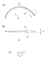
図2は、丸針12の拡大図であって、図2(A)は平面図、図2(B)は正面図、図2(C)は、図2(A)のA−A線断面図である。
2A and 2B are enlarged views of the
図2に示すように、丸針12の基端側に挟持部12bが形成されている。本実施形態においては、挟持部12bは、断面偏平形状に形成されており、組織を切り裂かないように挟持部12bの稜線12cには、切刃が形成されていない。また、図2(B)に示すように、この挟持部12bの稜線12cは、刺通時に徐々に組織を押し広げる様に緩やかなテーパを形成し、厚みtに対する幅wの偏平比が徐々に大きくなるように構成されている。最大偏平比はテーパ形状の終わりの基端側に形成されている。この最大偏平比は、刺通時に屈折しない程度で、結紮部を埋入させるために組織を押し広げられる程度にすることが好ましい。本実施形態においては、厚みtに対する幅wの最大偏平比は1:3.5〜4.0の範囲である。具体的には、丸針12の直径φ0.55mmの場合には、厚みtは0.25〜0.35mm、幅wは0.9mm〜1.0mmである。これにより、丸針12の刺通時に組織を押し広げることができ、すなわち刺通穴を拡張することができる。なお、本実施形態においては、偏平の幅広面は湾曲半径に直交する方向に形成されている。これにより、施術時の持針器36による挟持が容易になり、作業性を向上させることができる。
As shown in FIG. 2, a clamping
次に、本実施形態の両端針付縫合糸1を用いた重瞼埋没法の施術について簡単に説明する。
Next, the operation of the double burial method using the
両端針付縫合糸1は、背景技術で説明した重瞼埋没法の施術に用いることができる。特徴的な点は、本実施形態の両端針付縫合糸1を用いる場合には、縫合点A,Bのマーキング後に縫合点Aをメスや剪刀により切開する必要がない。すなわち、縫合点A,Bをマーキングした後、両端針付縫合糸1の丸針12を瞼板側の縫合点Aから皮膚側の縫合点Aに刺通する。丸針12の挟持部12bは、厚みtに対する幅wの最大偏平比が1:3.5〜4.0になるように構成されているので、刺通時に組織を押し広げることができる。これにより、施術後、縫合糸10、縫合糸10の結紮部を一旦押し広げられた組織に容易に埋入することができる。なお、重瞼埋没法の他の刺通工程は、従来同様に行うことができる。
The double-ended needle-attached
なお、本明細書で説明した重瞼埋没法の施術は一例であって、縫合により重瞼を形成する重瞼埋没法の種々のバリエーションにおいても本実施形態の両端針付縫合糸1を好適に適用することができる。 Note that the operation of the heavy burial embedding method described in this specification is an example, and the suture with a double-ended needle of this embodiment is suitably used in various variations of the heavy burial embedding method in which the heavy burial is formed by suturing. Can be applied.
また、本実施形態においては、両端針付縫合糸1の一方の丸針の挟持部を所定の最大偏平比を有するように構成したが、両方の丸針を同一の形状にしても良い。
In the present embodiment, the holding portion of one round needle of the double-ended needle-attached
更に、縫合糸の一端に丸針が固定された片針付縫合糸の丸針の挟持部を所定の最大偏平比を有するように構成しても好適である。この片針付縫合糸も背景技術で説明した重瞼埋没法に用いることができる。この場合において、図3(B)、(C)に相当する工程で、初期刺通時に皮膚側の縫合点Aから瞼板側の縫合点Aに刺通し、その後、瞼板側の縫合点Bから皮膚側の縫合点Bに順次刺通すれば良い。 Furthermore, it is also preferable that the holding part of the round needle of the single-needle suture thread having a round needle fixed to one end of the suture thread has a predetermined maximum flatness ratio. This single needle-attached suture can also be used in the heavy padding method described in the background art. In this case, in the step corresponding to FIGS. 3B and 3C, at the time of initial puncture, the suture point A on the skin side is pierced from the suture point A on the mortar plate side, and then the suture point B on the mortar plate side. It suffices to sequentially pierce the suture point B on the skin side.
1 両端針付縫合糸、10 縫合糸、12,14 丸針、12b 挟持部、12c 稜線、30 メス、32 切開部、34 角膜保護板、36 持針器、38 両端針付縫合糸、40,42 丸針、44 縫合糸、46 ブジー、48 結紮部。
DESCRIPTION OF
Claims (2)
少なくとも1つの丸針の直径は、0.3〜0.7mmであり、
前記丸針の基端部側を偏平にして形成された挟持部は、挟持部の厚みに対する幅の偏平比が徐々に大きくなり、その稜線は、刺通時に徐々に組織を押し広げられるようにテーパ形状に形成され、
前記丸針の挟持部の厚みと幅の最大偏平比が、1:3.5〜4.0であり、
前記最大偏平比を有する挟持部の幅により押し広げられた刺通穴の幅が、縫合糸の結紮部を埋入させるための幅を有することを特徴とする針付縫合糸。 A suture with a needle that is used in the method of burying a chisel to form a chisel, with a round needle fixed to one or both ends of the suture,
The diameter of the at least one round needle is 0.3-0.7 mm;
The clamping part formed with the base end side of the round needle flattened has a flattening ratio of the width with respect to the thickness of the clamping part gradually so that the ridge line can gradually spread the tissue during piercing. Formed in a tapered shape,
Maximum flattening ratio of the thickness and width of the clamping portion of the round needle, 1: 3.5 to 4.0 der is,
A suture with a needle characterized in that the width of the piercing hole expanded by the width of the holding portion having the maximum flatness ratio has a width for embedding the ligation portion of the suture.
少なくとも1つの針の直径は、0.3〜0.7mmであり、
前記針の基端部側を偏平にして形成された挟持部は、挟持部の厚みに対する幅の偏平比が徐々に大きくなり、その稜線は、刺通時に徐々に組織を押し広げられるようにテーパ形状に形成され、
前記針の挟持部の厚みと幅の最大偏平比が、1:3.5〜4.0であり、
前記最大偏平比を有する挟持部の幅により押し広げられた刺通穴の幅が、縫合糸の結紮部を埋入させるための幅を有することを特徴とする針。 A needle that is used in the method of burying a chisel to form a chisel and having a suture fixed to the proximal end,
The diameter of the at least one needle is 0.3-0.7 mm;
The pinching portion formed with the proximal end side of the needle flattened has a flattening ratio of the width with respect to the thickness of the pinching portion, and its ridge line is tapered so that the tissue is gradually spread during piercing. Formed into a shape,
Maximum flattening ratio of the thickness and width of the clamping portion of the needle, 1: 3.5 to 4.0 der is,
The needle characterized in that the width of the piercing hole expanded by the width of the holding portion having the maximum flatness ratio has a width for embedding the ligation portion of the suture thread .
Priority Applications (1)
| Application Number | Priority Date | Filing Date | Title |
|---|---|---|---|
| JP2003314008A JP3868410B2 (en) | 2003-09-05 | 2003-09-05 | Suture with needle |
Applications Claiming Priority (1)
| Application Number | Priority Date | Filing Date | Title |
|---|---|---|---|
| JP2003314008A JP3868410B2 (en) | 2003-09-05 | 2003-09-05 | Suture with needle |
Publications (3)
| Publication Number | Publication Date |
|---|---|
| JP2005080761A JP2005080761A (en) | 2005-03-31 |
| JP2005080761A5 JP2005080761A5 (en) | 2006-03-09 |
| JP3868410B2 true JP3868410B2 (en) | 2007-01-17 |
Family
ID=34414761
Family Applications (1)
| Application Number | Title | Priority Date | Filing Date |
|---|---|---|---|
| JP2003314008A Expired - Lifetime JP3868410B2 (en) | 2003-09-05 | 2003-09-05 | Suture with needle |
Country Status (1)
| Country | Link |
|---|---|
| JP (1) | JP3868410B2 (en) |
Families Citing this family (8)
| Publication number | Priority date | Publication date | Assignee | Title |
|---|---|---|---|---|
| EP1406545B1 (en) | 2001-06-14 | 2015-10-28 | Endoevolution, Llc | Apparatus and method for surgical suturing with thread management |
| US7976555B2 (en) | 2008-07-17 | 2011-07-12 | Endoevolution, Llc | Apparatus and method for minimally invasive suturing |
| US9775600B2 (en) | 2010-10-01 | 2017-10-03 | Endoevolution, Llc | Devices and methods for minimally invasive suturing |
| US8123764B2 (en) | 2004-09-20 | 2012-02-28 | Endoevolution, Llc | Apparatus and method for minimally invasive suturing |
| CA2640148C (en) | 2006-01-27 | 2014-09-09 | Suturtek Incorporated | Apparatus and method for tissue closure |
| WO2018119459A1 (en) | 2016-12-23 | 2018-06-28 | Brigham And Women's Hospital, Inc. | Systems and methods for suturing tissue |
| US20180242967A1 (en) | 2017-02-26 | 2018-08-30 | Endoevolution, Llc | Apparatus and method for minimally invasive suturing |
| US10292698B2 (en) | 2017-07-27 | 2019-05-21 | Endoevolution, Llc | Apparatus and method for minimally invasive suturing |
-
2003
- 2003-09-05 JP JP2003314008A patent/JP3868410B2/en not_active Expired - Lifetime
Also Published As
| Publication number | Publication date |
|---|---|
| JP2005080761A (en) | 2005-03-31 |
Similar Documents
| Publication | Publication Date | Title |
|---|---|---|
| US5336239A (en) | Surgical needle | |
| EP1726317B1 (en) | Surgical means for cosmetic surgery | |
| US5059207A (en) | Shaped needles for specialized surgical procedures | |
| US5433728A (en) | Surgical needle | |
| US9398900B2 (en) | Device and method for treating varicose veins | |
| KR101668663B1 (en) | The kit which using a stitching fiber and method thereof | |
| JPH07178103A (en) | Needle with dull point | |
| EP3622895B1 (en) | Needle instrument for orbital fat repositioning surgery | |
| JP3868410B2 (en) | Suture with needle | |
| JP2017504371A (en) | Medical tube insertion device and medical tube insertion treatment kit including the same | |
| US6582356B2 (en) | Method for magnifying penis and method for using endoscope for the same | |
| WO2018062284A1 (en) | Suture needle for uterine hemostatic compression | |
| JPS62101237A (en) | Operation needle | |
| CN209203375U (en) | A kind of bull bifurcated surgical stapling device | |
| US9706983B1 (en) | Method for suturing small skin wounds | |
| JPH0947457A (en) | Needle for buried suture and auxiliary tool for buried suture and buried suture operation method | |
| JP2001333909A (en) | Sutural needle for medical use | |
| CN216136053U (en) | Eyelid plate fixer | |
| WO1995034245A1 (en) | Safety lock needle | |
| JP2001333910A (en) | Medical suture needle | |
| CN114533161A (en) | Fusiform needle for minimally invasive repair of achilles tendon fracture and application thereof | |
| JP3212586U (en) | Orbital fat repositioning surgical needle instrument | |
| JP2006051103A (en) | Biological tissue closing implement and biological tissue closing device | |
| JP5709119B1 (en) | Bending needle for sternum suture | |
| JPH0332658A (en) | Marking needle for liver excision surgical operation |
Legal Events
| Date | Code | Title | Description |
|---|---|---|---|
| A521 | Request for written amendment filed |
Free format text: JAPANESE INTERMEDIATE CODE: A523 Effective date: 20060119 |
|
| A621 | Written request for application examination |
Free format text: JAPANESE INTERMEDIATE CODE: A621 Effective date: 20060119 |
|
| A871 | Explanation of circumstances concerning accelerated examination |
Free format text: JAPANESE INTERMEDIATE CODE: A871 Effective date: 20060119 |
|
| A975 | Report on accelerated examination |
Free format text: JAPANESE INTERMEDIATE CODE: A971005 Effective date: 20060209 |
|
| A131 | Notification of reasons for refusal |
Free format text: JAPANESE INTERMEDIATE CODE: A131 Effective date: 20060214 |
|
| A02 | Decision of refusal |
Free format text: JAPANESE INTERMEDIATE CODE: A02 Effective date: 20060516 |
|
| A521 | Request for written amendment filed |
Free format text: JAPANESE INTERMEDIATE CODE: A523 Effective date: 20060714 |
|
| A521 | Request for written amendment filed |
Free format text: JAPANESE INTERMEDIATE CODE: A523 Effective date: 20060724 |
|
| A911 | Transfer to examiner for re-examination before appeal (zenchi) |
Free format text: JAPANESE INTERMEDIATE CODE: A911 Effective date: 20060912 |
|
| TRDD | Decision of grant or rejection written | ||
| A01 | Written decision to grant a patent or to grant a registration (utility model) |
Free format text: JAPANESE INTERMEDIATE CODE: A01 Effective date: 20061003 |
|
| A61 | First payment of annual fees (during grant procedure) |
Free format text: JAPANESE INTERMEDIATE CODE: A61 Effective date: 20061010 |
|
| R150 | Certificate of patent or registration of utility model |
Ref document number: 3868410 Country of ref document: JP Free format text: JAPANESE INTERMEDIATE CODE: R150 Free format text: JAPANESE INTERMEDIATE CODE: R150 |
|
| FPAY | Renewal fee payment (event date is renewal date of database) |
Free format text: PAYMENT UNTIL: 20121020 Year of fee payment: 6 |
|
| R250 | Receipt of annual fees |
Free format text: JAPANESE INTERMEDIATE CODE: R250 |
|
| FPAY | Renewal fee payment (event date is renewal date of database) |
Free format text: PAYMENT UNTIL: 20121020 Year of fee payment: 6 |
|
| FPAY | Renewal fee payment (event date is renewal date of database) |
Free format text: PAYMENT UNTIL: 20131020 Year of fee payment: 7 |
|
| R250 | Receipt of annual fees |
Free format text: JAPANESE INTERMEDIATE CODE: R250 |
|
| R250 | Receipt of annual fees |
Free format text: JAPANESE INTERMEDIATE CODE: R250 |
|
| R250 | Receipt of annual fees |
Free format text: JAPANESE INTERMEDIATE CODE: R250 |
|
| R250 | Receipt of annual fees |
Free format text: JAPANESE INTERMEDIATE CODE: R250 |
|
| R250 | Receipt of annual fees |
Free format text: JAPANESE INTERMEDIATE CODE: R250 |
|
| R250 | Receipt of annual fees |
Free format text: JAPANESE INTERMEDIATE CODE: R250 |
|
| R250 | Receipt of annual fees |
Free format text: JAPANESE INTERMEDIATE CODE: R250 |
|
| EXPY | Cancellation because of completion of term |