JP3867724B2 - Surface condition inspection method, surface condition inspection apparatus and substrate inspection apparatus using the method - Google Patents
Surface condition inspection method, surface condition inspection apparatus and substrate inspection apparatus using the method Download PDFInfo
- Publication number
- JP3867724B2 JP3867724B2 JP2005032845A JP2005032845A JP3867724B2 JP 3867724 B2 JP3867724 B2 JP 3867724B2 JP 2005032845 A JP2005032845 A JP 2005032845A JP 2005032845 A JP2005032845 A JP 2005032845A JP 3867724 B2 JP3867724 B2 JP 3867724B2
- Authority
- JP
- Japan
- Prior art keywords
- hue
- inspection
- data
- image
- change
- Prior art date
- Legal status (The legal status is an assumption and is not a legal conclusion. Google has not performed a legal analysis and makes no representation as to the accuracy of the status listed.)
- Expired - Fee Related
Links
- 238000007689 inspection Methods 0.000 title claims description 210
- 238000000034 method Methods 0.000 title claims description 57
- 239000000758 substrate Substances 0.000 title claims description 38
- 230000008859 change Effects 0.000 claims description 120
- 239000013598 vector Substances 0.000 claims description 67
- 238000004364 calculation method Methods 0.000 claims description 37
- 238000003384 imaging method Methods 0.000 claims description 36
- 229910000679 solder Inorganic materials 0.000 claims description 34
- 238000005286 illumination Methods 0.000 claims description 16
- 238000005476 soldering Methods 0.000 claims description 14
- 230000014509 gene expression Effects 0.000 claims description 13
- 239000003086 colorant Substances 0.000 claims description 12
- 239000002131 composite material Substances 0.000 claims description 10
- 238000012545 processing Methods 0.000 description 35
- 230000008569 process Effects 0.000 description 32
- 230000002950 deficient Effects 0.000 description 17
- 238000000605 extraction Methods 0.000 description 17
- 230000003287 optical effect Effects 0.000 description 11
- 238000012360 testing method Methods 0.000 description 7
- 230000005540 biological transmission Effects 0.000 description 5
- 230000004308 accommodation Effects 0.000 description 4
- 238000003491 array Methods 0.000 description 3
- 238000006243 chemical reaction Methods 0.000 description 3
- 238000013523 data management Methods 0.000 description 3
- 230000006870 function Effects 0.000 description 3
- 230000015572 biosynthetic process Effects 0.000 description 2
- 238000013500 data storage Methods 0.000 description 2
- 238000009792 diffusion process Methods 0.000 description 2
- 230000002093 peripheral effect Effects 0.000 description 2
- 101000911772 Homo sapiens Hsc70-interacting protein Proteins 0.000 description 1
- 101001139126 Homo sapiens Krueppel-like factor 6 Proteins 0.000 description 1
- 101000710013 Homo sapiens Reversion-inducing cysteine-rich protein with Kazal motifs Proteins 0.000 description 1
- 101000661807 Homo sapiens Suppressor of tumorigenicity 14 protein Proteins 0.000 description 1
- 230000003321 amplification Effects 0.000 description 1
- 238000013459 approach Methods 0.000 description 1
- 230000008901 benefit Effects 0.000 description 1
- 238000012937 correction Methods 0.000 description 1
- 230000007423 decrease Effects 0.000 description 1
- 230000007547 defect Effects 0.000 description 1
- 238000013461 design Methods 0.000 description 1
- 238000010586 diagram Methods 0.000 description 1
- 239000000284 extract Substances 0.000 description 1
- 230000005484 gravity Effects 0.000 description 1
- 238000003199 nucleic acid amplification method Methods 0.000 description 1
- 238000002310 reflectometry Methods 0.000 description 1
- 230000004044 response Effects 0.000 description 1
Images


Classifications
-
- G—PHYSICS
- G01—MEASURING; TESTING
- G01R—MEASURING ELECTRIC VARIABLES; MEASURING MAGNETIC VARIABLES
- G01R31/00—Arrangements for testing electric properties; Arrangements for locating electric faults; Arrangements for electrical testing characterised by what is being tested not provided for elsewhere
- G01R31/28—Testing of electronic circuits, e.g. by signal tracer
- G01R31/302—Contactless testing
- G01R31/308—Contactless testing using non-ionising electromagnetic radiation, e.g. optical radiation
- G01R31/309—Contactless testing using non-ionising electromagnetic radiation, e.g. optical radiation of printed or hybrid circuits or circuit substrates
-
- G—PHYSICS
- G01—MEASURING; TESTING
- G01N—INVESTIGATING OR ANALYSING MATERIALS BY DETERMINING THEIR CHEMICAL OR PHYSICAL PROPERTIES
- G01N21/00—Investigating or analysing materials by the use of optical means, i.e. using sub-millimetre waves, infrared, visible or ultraviolet light
- G01N21/84—Systems specially adapted for particular applications
- G01N21/88—Investigating the presence of flaws or contamination
- G01N21/95—Investigating the presence of flaws or contamination characterised by the material or shape of the object to be examined
- G01N21/956—Inspecting patterns on the surface of objects
- G01N21/95684—Patterns showing highly reflecting parts, e.g. metallic elements
-
- G—PHYSICS
- G06—COMPUTING; CALCULATING OR COUNTING
- G06T—IMAGE DATA PROCESSING OR GENERATION, IN GENERAL
- G06T7/00—Image analysis
- G06T7/0002—Inspection of images, e.g. flaw detection
- G06T7/0004—Industrial image inspection
-
- G—PHYSICS
- G06—COMPUTING; CALCULATING OR COUNTING
- G06T—IMAGE DATA PROCESSING OR GENERATION, IN GENERAL
- G06T7/00—Image analysis
- G06T7/90—Determination of colour characteristics
-
- G—PHYSICS
- G06—COMPUTING; CALCULATING OR COUNTING
- G06T—IMAGE DATA PROCESSING OR GENERATION, IN GENERAL
- G06T2207/00—Indexing scheme for image analysis or image enhancement
- G06T2207/10—Image acquisition modality
- G06T2207/10024—Color image
-
- G—PHYSICS
- G06—COMPUTING; CALCULATING OR COUNTING
- G06T—IMAGE DATA PROCESSING OR GENERATION, IN GENERAL
- G06T2207/00—Indexing scheme for image analysis or image enhancement
- G06T2207/30—Subject of image; Context of image processing
- G06T2207/30108—Industrial image inspection
- G06T2207/30152—Solder
Landscapes
- Engineering & Computer Science (AREA)
- Physics & Mathematics (AREA)
- General Physics & Mathematics (AREA)
- Computer Vision & Pattern Recognition (AREA)
- Health & Medical Sciences (AREA)
- Theoretical Computer Science (AREA)
- Life Sciences & Earth Sciences (AREA)
- General Engineering & Computer Science (AREA)
- Toxicology (AREA)
- Chemical & Material Sciences (AREA)
- Analytical Chemistry (AREA)
- Biochemistry (AREA)
- General Health & Medical Sciences (AREA)
- Immunology (AREA)
- Pathology (AREA)
- Quality & Reliability (AREA)
- Electromagnetism (AREA)
- Investigating Materials By The Use Of Optical Means Adapted For Particular Applications (AREA)
- Length Measuring Devices By Optical Means (AREA)
Description
この発明は、表面の鏡面性が高く、かつその表面に傾斜面が含まれる物体を検査対象として、その検査対象物を撮像して得られた画像を用いて表面状態の良否を検査する方法および装置に関する。また、この発明は、複数のはんだ付け部位が設定された基板を検査対象として、その基板上の各はんだ付け部位のはんだの表面状態を検査する装置に関する。 The present invention relates to a method for inspecting the quality of a surface state using an image obtained by imaging an object to be inspected using an object whose surface has a high specularity and includes an inclined surface on the surface, and Relates to the device. The present invention also relates to an apparatus for inspecting the surface state of the solder at each soldering site on the board, with a board on which a plurality of soldering sites are set as an inspection target.
出願人は、以前に、はんだ付け部位の鏡面反射性を利用して、画像処理の手法により基板上のはんだ付け部位を自動検査する装置を開発した(特許文献1参照。)。 The applicant has previously developed an apparatus for automatically inspecting a soldering site on a substrate by an image processing technique using the specular reflectivity of the soldering site (see Patent Document 1).
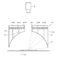
図16は、上記特許文献1に開示された基板検査装置の構成および検査の原理を示す。この検査装置は、赤、緑、青の各色彩光を有する3個の光源8,9,10と撮像装置3とにより検査対象の画像を生成するものである。図中の1は基板、2は検査対象のはんだであり、各光源8,9,10は、基板1やはんだ2に対してそれぞれ異なる仰角方向に配備される。一方、撮像装置3は、前記はんだ2を真上位置から撮像するように配備される。
FIG. 16 shows the configuration of the substrate inspection apparatus disclosed in
上記構成によれば、各光源8,9,10からの色彩光は、それぞれはんだ2の表面に異なる方向から照射される。また、はんだの傾斜面に対し、その傾斜に直交する方向を軸として撮像装置3の方向に対称な方向からの光が照射されると、その光の鏡面反射光は撮像装置3に導かれる。すなわち、はんだ表面から撮像装置3に入射する鏡面反射光の色彩は、そのはんだ表面の傾きによって異なるものとなる。
According to the above configuration, the colored light from each of the
図16に示した光学系では、はんだ2から見て、赤色光源8の仰角が最も大きく、青色光源10の仰角が最も小さくなるようにし、これらの光源8,10の間に緑色光源9が位置するように、各光源8,9,10を配置している。したがって、前記はんだ2が球体状のはんだであれば、図17に示すように、中央部の平坦面が赤色の画像領域として、基板面の近傍の急傾斜面が青色の画像領域として、またこれらの中間に位置する比較的緩やかな傾斜面(暖傾斜面)が緑色の画像領域として、それぞれ切り分けられた画像が生成されることになる。
In the optical system shown in FIG. 16, the elevation angle of the
また、はんだのフィレットを検査する場合には、図18に示すように、上方の急傾斜面では青、中間の暖傾斜面では緑、基板面の近傍の平坦に近い面では赤、というように、各色彩による画像領域が切り分けられる。なお、図18中のS1は、ランドの形成範囲である。 Also, when inspecting a solder fillet, as shown in FIG. 18, the upper steeply inclined surface is blue, the intermediate warm inclined surface is green, the substrate surface near the flat surface is red, and so on. The image area by each color is cut out. In addition, S1 in FIG. 18 is a land formation range.
このように、はんだの画像では、その表面の勾配の変化に応じて赤、緑、青の各色彩領域に区分けされた画像が生成される。よって、あらかじめ良好な形状のはんだの画像における各色彩のパターンを登録しておき、検査対象の画像上における各色彩のパターンを前記登録パターンと比較することにより、はんだの表面状態の良否を判別することができる。 In this manner, in the solder image, an image divided into red, green, and blue color regions is generated in accordance with the change in the gradient of the surface. Therefore, each color pattern in the image of the solder with a good shape is registered in advance, and the quality of the solder surface state is determined by comparing each color pattern on the image to be inspected with the registered pattern. be able to.
従来の検査装置では、上記の原理に基づき、あらかじめディジタルカラー画像を構成するR,G,Bの各階調データ毎に所定の2値化しきい値を設定しておき、前記撮像装置3により得た画像をこれら2値化しきい値により2値化することによって、赤、緑、青の各色彩領域を抽出するようにしている。また、これらの色彩領域について、あらかじめ良好な形状のはんだの画像において抽出された領域の位置、形状、大きさなどを登録しておき、検査対象の画像における色彩領域の抽出結果を登録されたデータと比較することにより、はんだの表面状態の良否を判別するようにしている。
In the conventional inspection apparatus, based on the above principle, a predetermined binarization threshold value is set in advance for each of the R, G, and B gradation data constituting the digital color image, and obtained by the
ところで、図16に示した光学系では、温度や使用時間により照明光の明るさや色合いが変動すると、画像上の明るさや色合いも変動すると考えられる。このような画像の明るさや色合いの変動は、色彩領域の抽出結果に影響を及ぼすおそれがある。特に、はんだの検査では、表面状態が良好であっても、色合いの変化により各色彩領域の特徴量が変動すると、良品の基準値をクリアできなくなり、不良と判定される可能性がある。 By the way, in the optical system shown in FIG. 16, when the brightness and hue of the illumination light vary depending on the temperature and usage time, it is considered that the brightness and hue on the image also vary. Such variations in image brightness and hue may affect the extraction result of the color region. In particular, in the solder inspection, even if the surface state is good, if the feature amount of each color region varies due to a change in hue, the reference value for a non-defective product cannot be cleared, and it may be determined as defective.
したがって、検査の精度を維持するには、2値化しきい値を頻繁に変更するのが望ましい。しかしながら、この種の検査装置では、次々に基板の供給を受けて検査を繰り返すことが要求されるから、2値化しきい値の更新によって検査を中断すると、処理効率の低下を招くおそれがある。また、2値化しきい値を更新するタイミングを正確に判断するのも困難である。 Therefore, it is desirable to frequently change the binarization threshold in order to maintain inspection accuracy. However, in this type of inspection apparatus, it is required to repeat the inspection by receiving the substrate one after another. If the inspection is interrupted by updating the binarization threshold value, the processing efficiency may be lowered. It is also difficult to accurately determine the timing for updating the binarization threshold.
一方、上記の2値化処理に代わる処理として、実装状態が良好な基板の画像をモデル画像としたパターンマッチング処理を実行する方法がある。この方法では、検査対象の画像とモデル画像との間で正規化相関演算を実行するので、照明が変動しても、判別のためのしきい値を変更せずに対応できるというメリットがある。しかしながら、検査対象のはんだの形状が少し変化しただけでも相関値が低下してしまい、判別処理にかかる正答率が悪い、という問題がある。 On the other hand, as a process replacing the above binarization process, there is a method of executing a pattern matching process using an image of a board with a good mounting state as a model image. This method has an advantage that the normalized correlation calculation is performed between the image to be inspected and the model image, so that even if the illumination fluctuates, it can be handled without changing the threshold value for discrimination. However, there is a problem that even if the shape of the solder to be inspected is slightly changed, the correlation value is lowered and the correct answer rate for the discrimination processing is poor.
また、近年の基板では、部品が微小化し、また多数の部品が実装される傾向にあるため、各部品に対するランドの面積を周辺の実装密度に応じて調整する必要が生じている。このため、同一種の部品であっても、周囲に実装される部品が比較的少ない場合と、周囲に多数の部品が実装される場合とで、ランドの大きさが異なるようになる。これを受けて、はんだフィレットの勾配も部品の実装位置によって異なるようになるから、フィレットの画像における各色彩領域の大きさや形状なども異なるものになる。 Further, in recent boards, there is a tendency that parts are miniaturized and a large number of parts are mounted. Therefore, it is necessary to adjust the land area for each part according to the peripheral mounting density. For this reason, even if it is the same kind of component, the size of the land differs between the case where a relatively small number of components are mounted around and the case where a large number of components are mounted around. In response to this, the gradient of the solder fillet also varies depending on the mounting position of the component, so the size and shape of each color region in the fillet image also differ.
たとえば、周囲に実装される部品が比較的少ない場合には、はんだ付けの安定のためにランドが大きめに形成されるから、フィレットの勾配は比較的緩やかになり、赤、緑、青の各色彩領域が適度に出現する。一方、実装密度の高い領域に実装される部品では、ランドの面積を小さくせざるを得ないから、フィレットの勾配が急になり、画像上では青色領域が優勢になり、緑色領域や赤色領域は出現しにくくなる。このように、同一種の部品であっても、画像上に現れる色彩領域の分布状態が異なるため、各色彩領域に対する判定基準値を部品毎に設定しなければ、検査精度を確保するのは困難となる。 For example, if there are relatively few parts mounted around, the land will be formed larger for soldering stability, so the fillet gradient will be relatively gentle, and red, green, and blue colors. The area appears moderately. On the other hand, in parts mounted in areas with high mounting density, the land area must be reduced, so the slope of the fillet becomes steep, the blue area predominates on the image, and the green and red areas It becomes difficult to appear. In this way, even in the same type of component, the distribution state of the color regions appearing on the image is different, so it is difficult to ensure inspection accuracy unless the determination reference value for each color region is set for each component. It becomes.
この発明は、上記の問題に着目してなされたもので、傾斜面の状態を検査する際に、画像の明るさや色合いが変動しても、信頼度の高い検査を実行できるようにすることを第1の目的とする。 The present invention has been made paying attention to the above-mentioned problem. When inspecting the state of an inclined surface, it is possible to perform a highly reliable inspection even if the brightness and hue of an image fluctuate. The first purpose.
さらにこの発明は、勾配が急であったり、または反対に緩やかであって、すべての光源に対応する色彩領域が出現しにくいような検査対象物についても、精度の高い検査を実行できるようにすることを、第2の目的とする。 Furthermore, the present invention makes it possible to perform a highly accurate inspection even on an inspection object in which the gradient is steep or, conversely, the color region corresponding to all the light sources hardly appears. This is the second purpose.
この発明にかかる表面状態検査方法は、表面に傾斜面を有する検査対象物に対し、互いに異なる色彩光を発光する複数の光源を前記検査対象物の配置位置から見た仰角が異なるように配列して照明し、前記検査対象物の配置位置の上方に設置した撮像手段により得られたカラー画像を用いて前記検査対象物の表面状態を検査するものである。この発明では、前記画像中の検査対象物を含む検査領域を設定し、検査領域内の複数の画素につき、それぞれ各光源の配列に対応する色相の変化の方向に沿って増加する1次元の色相データを算出するための演算式に当該画素の画像データをあてはめて、前記色相データを算出する第1のステップと、第1のステップの算出結果を用いて、検査領域において、色相データの変化量が所定のしきい値以上になる方向を抽出し、その抽出した方向を各光源の配列に対応した色相の変化が生じている方向として特定する第2のステップと、第2のステップで特定された方向をあらかじめ設定された基準の方向と比較する第3のステップと、第3のステップにおける比較結果に基づき、前記検査対象物の表面状態の良否を判別する第4のステップとを、実行する。 In the surface condition inspection method according to the present invention, a plurality of light sources that emit different colored lights are arranged with respect to an inspection object having an inclined surface on the surface so that elevation angles viewed from the arrangement position of the inspection object are different. And inspecting the surface state of the inspection object using a color image obtained by an imaging means installed above the position where the inspection object is arranged. In the present invention, an inspection area including an inspection object in the image is set, and a one-dimensional hue that increases along a direction of a hue change corresponding to each light source array for a plurality of pixels in the inspection area. A first step of calculating the hue data by applying the image data of the pixel to an arithmetic expression for calculating the data, and a change amount of the hue data in the inspection region using the calculation result of the first step Is extracted in the second step, and the second direction is specified as the direction in which the hue change corresponding to the arrangement of each light source occurs. a third step of comparing the direction of the preset reference direction, based on the comparison result of the third step, a fourth step of determining the quality of the surface state of the inspection object To run.
互いに異なる色彩光を発光する複数の光源を検査対象物から見た仰角が異なるように配置して照明すると、撮像手段により得られた画像中の傾斜面に対応する部分では、その勾配の大きさに応じた色彩が現れる。また、前記図17,18の例の平坦面、暖傾斜面、急傾斜面のように、傾斜面の勾配の大きさが徐々に変化する場合、この変化の方向において、各光源に対応する色彩が検査対象物から見た光源の配置の順(仰角の大きさの順)に並んで現れると考えることができる。 When a plurality of light sources that emit different colored lights are arranged and illuminated so that the elevation angles viewed from the inspection object are different, the magnitude of the gradient is obtained at the portion corresponding to the inclined surface in the image obtained by the imaging means. Depending on the color appears. Further, when the slope of the inclined surface gradually changes, such as the flat surface, warm inclined surface, and steeply inclined surface in the examples of FIGS. 17 and 18, the color corresponding to each light source in the direction of the change. Can be considered to appear side by side in the order of the arrangement of the light sources as viewed from the inspection object (in order of the magnitude of the elevation angle).
この発明において、「各光源の配列に対応した色相の変化」とは、各光源が発する色彩(発光色)を、検査対象物から見た各光源の配列の順序(仰角が小さい方から大きい方に向かう順またはその逆の順序をいう。以下も同じ。)に沿って並べたときに、その並び方向に沿って現れる色相の変化ということができる。たとえば、前記した図16の光学系によれば、赤、緑、青の順、または青、緑、赤の順に各色彩を並べたときの色相(色合い)の変化として捉えることができる。 In the present invention, the “change in hue corresponding to the arrangement of each light source” means the color (emission color) emitted from each light source in the order of the arrangement of each light source as viewed from the inspection object (the one with the smallest elevation angle to the larger one). It can be said that the hue changes along the arrangement direction when arranged along the line. For example, according to the optical system shown in FIG. 16, it can be understood as a change in hue (hue) when colors are arranged in the order of red, green, and blue, or in the order of blue, green, and red.
前記したように、傾斜面に対応する部分の画像では、その勾配の大きさが変化する方向に沿って、各光源に対応する色彩が、前記検査対象物から見た各光源の配列の順に並んで現れる。すなわち、この並び方向に、「各光源の配列に対応した色相の変化」が現れていることになる。よって、各光源の配列に対応した色相の変化が生じている方向は、傾斜面の勾配の大きさが変化している方向(勾配が緩やかな部分から急な部分に向かう方向、または勾配が急な部分から緩やかな部分に向かう方向)を示す、と考えることができる。
この発明では、検査領域内の複数の画素につき、それぞれ各光源の配列に対応する色彩の変化の方向に沿って増加する一次元の色相データを算出するので、処理対象の画素の色彩が、配列の一端部にある光源(仰角が最も大きい光源または仰角が最も小さい光源)の発光色に近づくほど、色相データの値は大きくなる。したがって、検査領域において、各光源の配列に対応する色彩の変化の方向、すなわち傾斜面の勾配の大きさが変化している方向における色相データの変化量は、他の方向におけるものより大きくなると考えられる。
As described above, in the image of the portion corresponding to the inclined surface, the color corresponding to each light source is arranged in the order of the arrangement of each light source viewed from the inspection object along the direction in which the magnitude of the gradient changes. Appears at That is, the “change in hue corresponding to the arrangement of each light source” appears in this arrangement direction. Therefore, the direction in which the hue change corresponding to the arrangement of each light source occurs is the direction in which the gradient of the inclined surface changes (the direction from a gentle gradient to a steep portion, or a sharp gradient). It can be considered to indicate a direction from a gentle part to a gentle part.
In the present invention, for a plurality of pixels in the inspection region, one-dimensional hue data that increases along the direction of color change corresponding to each light source array is calculated, so that the color of the pixel to be processed is an array The value of the hue data increases as it approaches the emission color of the light source (the light source with the highest elevation angle or the light source with the smallest elevation angle) at one end. Therefore, in the inspection area, the change amount of the hue data in the direction of the color change corresponding to the arrangement of each light source, that is, the direction in which the gradient of the inclined surface is changing is considered to be larger than that in the other direction. It is done.
画像上の明るさや色合いが変動しても、各光源の配列に対応して色相の変化が生じる方向は、変化しないと考えることができる。よって、あらかじめ、モデルの対象物の画像を用いるなどして、各光源の配列に対応した色相の変化が生じる基準の方向を設定し、検査対象の画像で抽出された方向を基準の方向と比較することによって、傾斜面の勾配が変化する方向の適否を判別することができる。 It can be considered that the direction in which the hue changes corresponding to the arrangement of the light sources does not change even if the brightness or hue on the image varies. Therefore, using a model object image in advance, set a reference direction that causes a hue change corresponding to each light source array, and compare the direction extracted from the image to be inspected with the reference direction. By doing so, it is possible to determine whether or not the direction in which the gradient of the inclined surface changes is appropriate.
また、同種の検査対象物であるのに、勾配の大きさにばらつきがある場合でも、勾配の方向は変化しないと考えられる。したがって、これらの検査対象物の1つについて前記基準の方向を設定すれば、その設定データを他の検査対象物にも適用することができ、検査情報の教示を効率良く行うことが可能になる。 Further, even if the inspection object is of the same type, the gradient direction is considered not to change even if the gradient size varies. Therefore, if the reference direction is set for one of these inspection objects, the setting data can be applied to other inspection objects, and the inspection information can be efficiently taught. .
上記の表面状態検査方法の好ましい態様では、前記複数の光源は、前記検査対象物に対し、それぞれの発光色が色相環上の色相変化の方向に沿って並ぶように配列される。たとえば、前記光源として、赤色光、緑色光、青色光をそれぞれ発光する3個の光源を用いる場合には、前記仰角が赤、緑、青または青、緑、赤の順に大きくなるように、各光源が配置されることになる。また、第1のステップでは、色相環上の各光源の配列に対応する範囲における処理対象の画素の色相の位置を求める演算式を用いて、処理対象の画素の色相データを算出する。 In a preferred aspect of the above surface condition inspection method, the plurality of light sources are arranged so that the respective emission colors are aligned along the direction of hue change on the hue circle with respect to the inspection object. For example, when three light sources that respectively emit red light, green light, and blue light are used as the light source, each of the elevation angles increases in the order of red, green, blue, blue, green, and red. A light source will be arranged. In the first step, the hue data of the pixel to be processed is calculated using an arithmetic expression for obtaining the hue position of the pixel to be processed in a range corresponding to the arrangement of the light sources on the hue circle.
上記態様では、複数の光源が色相環上の色相変化の方向に沿った順序で配列されるので、画像上における各光源の配列に対応した色相の変化も、色相環の変化に対応するものとなる。また、色相環上の各光源の配列に対応する範囲における処理対象の画素の色相の位置を求める演算式により算出された色相データは、各光源の配列に対応する色相の変化の方向に沿って値が増加するものとなる。 In the above aspect, since the plurality of light sources are arranged in the order along the direction of the hue change on the hue ring, the change in hue corresponding to the arrangement of each light source on the image also corresponds to the change in the hue ring. Become. Further, the hue data calculated by the arithmetic expression for obtaining the position of the hue of the pixel to be processed in the range corresponding to the arrangement of the light sources on the hue circle is along the direction of the change of the hue corresponding to the arrangement of the light sources. The value will increase.
表面状態検査方法の他の好ましい態様では、前記第1のステップにおいて、検査対象物の配置位置から見た仰角が最も小さい光源または最も大きい光源に対応する色成分について他の色成分に対する強度比または全ての色成分の総和(すなわち明度)に対する強度比を求める演算式を用いて、処理対象の画像の色相データを算出する。 In another preferred aspect of the surface state inspection method, in the first step, the intensity ratio of the color component corresponding to the light source having the smallest elevation angle or the largest light source viewed from the arrangement position of the inspection object or the other color component or The hue data of the image to be processed is calculated using an arithmetic expression for obtaining an intensity ratio with respect to the sum (ie, brightness) of all color components.
たとえば、前記図16に示した光学系を使用する場合、青色光源10に対応する青色成分、すなわち階調データBに着目すると、この階調データBは、勾配が急になるほど大きくなり、勾配が緩やかになるほど小さくなると考えることができる。したがって、この階調データBについて、他の色成分(階調データR,G)に対する比率(たとえばB/R、もしくはB/(R+G))または明度に対する比率(B/(R+G+B))を求め、これを色相データとすることができる。この色相データも、各光源の配置に対応した色相の変化の方向に沿って値が増加するものとなる。
For example, when the optical system shown in FIG. 16 is used, paying attention to the blue component corresponding to the blue
表面状態検査方法のさらに好ましい態様では、第2のステップにおいて、検査領域内の複数の方向において、それぞれ前記色相データの変化量を算出するステップと、前記方向毎の色相データの変化量により特定される複数のベクトルの合成ベクトルを設定するステップとを実行する。そして、設定された合成ベクトルの長さが前記しきい値以上であるとき、この合成ベクトルが示す方向を前記各光源の配列に対応した色相の変化が生じている方向として特定する。 In a further preferred aspect of the surface condition inspection method, the second step is specified by a step of calculating a change amount of the hue data in each of a plurality of directions in the inspection region, and a change amount of the hue data for each direction. And a step of setting a composite vector of the plurality of vectors. When the length of the set composite vector is equal to or greater than the threshold value, the direction indicated by the composite vector is specified as the direction in which the hue change corresponding to the arrangement of the light sources occurs.
なお、上記の態様におけるしきい値は、検査の目的に合わせて設定されるのが望ましい。また、しきい値よりも短い合成ベクトルしか抽出されない場合には、検査領域には、良好な傾斜面が存在しないものとみなすのが望ましい。 Note that the threshold value in the above aspect is desirably set in accordance with the purpose of the inspection. In addition, when only a combined vector shorter than the threshold value is extracted, it is desirable to consider that there is no good inclined surface in the inspection region.
つぎに、この発明にかかる表面状態検査装置は、互いに異なる色彩光を発光する複数の光源を検査対象物の配置位置から見た仰角が異なるように配列して成る照明手段と、前記検査対象物の配置位置の上方に配備された撮像手段と、前記照明手段の各光源を点灯させた状態で前記撮像手段により生成された画像を取り込む画像入力手段と、前記画像入力手段が入力した画像中の検査対象物を含む領域を設定する領域設定手段と、前記領域設定手段により設定された検査領域内の複数の画素につき、それぞれ各光源の配列に対応する色相の変化の方向に沿って増加する1次元の色相データを算出するための演算式に当該画素の画像データをあてはめて、前記色相データを算出する色相データ算出手段と、前記色相データ算出手段による演算の結果を用いて、前記検査領域において、色相データの変化量が所定のしきい値以上になる方向を抽出し、その抽出された方向を前記各光源の配列に対応した色相の変化が生じている方向として特定する方向特定手段と、前記検査対象物の表面状態が良好であるときに前記方向特定手段により特定されるべき方向を、基準の方向として登録する登録手段と、前記方向特定手段により特定された方向を、前記登録手段により登録された基準の方向と比較して、前記検査対象物の表面状態の良否を判別する判別手段と、前記判別手段による判別結果を出力する出力手段とを具備する。 Next, the surface condition inspection apparatus according to the present invention includes a lighting unit in which a plurality of light sources that emit different colored lights are arranged so as to have different elevation angles when viewed from the arrangement position of the inspection object, and the inspection object An image input means arranged above the arrangement position, an image input means for capturing an image generated by the image pickup means with each light source of the illumination means turned on, and an image input by the image input means An area setting means for setting an area including an inspection object, and a plurality of pixels in the inspection area set by the area setting means, each increasing along a hue change direction corresponding to each light source array 1 By applying the image data of the pixel to the calculation formula for calculating the two-dimensional hue data, the hue data calculating means for calculating the hue data, and the result of the calculation by the hue data calculating means Using, in the examination region, the direction in which the change amount of the hue data are extracted in a direction equal to or greater than a predetermined threshold value, change in hue corresponding to the extracted direction sequence of each light source is generated Specified by the direction specifying means, the registration means for registering the direction to be specified by the direction specifying means when the surface condition of the inspection object is good, and the direction specifying means A determination means for comparing the reference direction registered by the registration means with the reference direction to determine whether the surface condition of the inspection object is good, and an output means for outputting a determination result by the determination means. .
上記において、照明手段は、たとえば色彩毎に異なる径を有するリング状の光源を中心を合わせて配列したものとすることができる。また同色の光を発光する複数の発光体(LEDなど)をリング状に配列したものを、1つの光源として使用することもできる。また光源はリング状に限らず、ライン状の光源を用いることもできる。 In the above, the illumination means may be, for example, a ring-shaped light source having a different diameter for each color and arranged centering on the center. Further, a plurality of light emitters (such as LEDs) that emit light of the same color arranged in a ring shape can be used as one light source. The light source is not limited to a ring shape, and a line light source can also be used.
撮像手段は、各色彩毎の画像信号を生成可能なCCDカメラにより構成することができる。照明手段にリング状の光源を用いる場合、撮像手段は、各光源の中心軸に光軸を合わせた状態で、鉛直方向に向けて配備されるのが望ましい。 The imaging means can be constituted by a CCD camera capable of generating an image signal for each color. When a ring-shaped light source is used as the illumination unit, the imaging unit is preferably arranged in the vertical direction with the optical axis aligned with the central axis of each light source.
画像入力手段、色相データ算出手段、方向特定手段、登録手段、判別手段、出力手段は、同一の筐体内に配備することができる。このうち、色相データ算出手段、方向特定手段、登録手段、判別手段は、これらの手段の処理を実行するためのプログラムが組み込まれたコンピュータにより構成することができる。 The image input means, the hue data calculation means, the direction identification means, the registration means, the determination means, and the output means can be arranged in the same casing. Among these, the hue data calculation means, the direction identification means, the registration means, and the discrimination means can be configured by a computer in which a program for executing the processing of these means is incorporated .
画像入力手段には、前記撮像手段からの画像信号を増幅処理するための増幅回路や、この画像信号をディジタル変換するためのA/D変換回路などを含めることができる。ただし、前記撮像手段にディジタルカメラを使用した場合には、画像入力手段は、ディジタルのカラー画像データを取り込むための入力ポートとして構成することができる。 The image input means can include an amplifier circuit for amplifying the image signal from the imaging means, an A / D conversion circuit for digitally converting the image signal, and the like. However, when a digital camera is used as the imaging means, the image input means can be configured as an input port for capturing digital color image data.
色相データ算出手段は、前記した第1のステップを実行するためのものであり、方向特定手段は第2のステップを実行するためのものであり、判別手段は、第3および第4のステップを実行するためのものである。登録手段は、前記照明手段や撮像手段を用いて生成された検査対象物の良品モデルの画像が入力されたときに、その画像から抽出された基準の方向をコンピュータのメモリに登録するように構成することができる。たとえば、良品モデルの画像上に検査領域を設定する操作が行われたときに、その領域内の画像データを前記抽出手段に処理させ、抽出された方向を基準の方向としてメモリに保存する手段を、登録手段とすることができる。または、良品モデルの画像上で各光源に対応する色彩が光源の配置に対応する順序で並ぶ方向を指定する操作を受け付けて、その方向を基準の方向としてメモリに保存する手段を、登録手段としてもよい。 The hue data calculation means is for executing the first step described above, the direction specifying means is for executing the second step, and the determination means is the third and fourth steps. It is for execution. The registration unit is configured to register a reference direction extracted from the image in a computer memory when an image of a non-defective model of the inspection object generated using the illumination unit or the imaging unit is input. can do. For example, when an operation for setting an inspection area on an image of a non-defective model is performed, image data in the area is processed by the extraction unit, and the extracted direction is stored in a memory as a reference direction. , A registration means. Alternatively, a means for accepting an operation for designating a direction in which colors corresponding to each light source are arranged in an order corresponding to the arrangement of the light sources on the non-defective model image, and storing the direction in the memory as a reference direction as a registration means. Also good.
出力手段は、前記判別手段による判別結果を表示装置に表示する表示用インターフェースや、判別結果を外部装置に出力する出力インターフェースとして構成することができる。このほか、出力手段は、前記判別結果を、フレキシブルディスク、CD−R、光磁気ディスクなどの記憶媒体に記録する手段として構成することもできる。 The output means can be configured as a display interface for displaying the determination result by the determination means on a display device, or an output interface for outputting the determination result to an external device. In addition, the output means can be configured as means for recording the determination result on a storage medium such as a flexible disk, a CD-R, or a magneto-optical disk.
好ましい態様にかかる表面状態検査装置では、前記照明手段の各光源は、前記検査対象物に対し、それぞれの発光色が色相環上の色相変化の方向に沿って並ぶように配列される。また色相データ算出手段は、色相環上の各光源の配列に対応する範囲における処理対象の画素の色相の位置を求める演算式による演算式を用いて、前記色相データを算出する。
前記照明手段の好ましい構成では、赤色光、緑色光、青色光をそれぞれ発光する3個の光源が、赤、緑、青または青、緑、赤の順に前記仰角が大きくなるような順序で配置される。
In the surface condition inspection apparatus according to a preferred aspect, the light sources of the illuminating means are arranged so that the respective emission colors are aligned along the direction of hue change on the hue circle with respect to the inspection object. The hue data calculation means calculates the hue data using an arithmetic expression based on an arithmetic expression for obtaining the hue position of the pixel to be processed in a range corresponding to the arrangement of the light sources on the hue circle.
In a preferred configuration of the illumination means, three light sources that respectively emit red light, green light, and blue light are arranged in such an order that the elevation angle increases in the order of red, green, blue or blue, green, and red. The
他の好ましい態様にかかる表面状態検査装置では、前記色相データ算出手段は、前記検査対象物の配置位置から見た仰角が最も小さい光源または最も大きい光源に対応する色成分について他の色成分に対する強度比または全ての色成分の総和に対する強度比を求める演算式を用いて、処理対象の画素の色相データを算出する。この態様においても、前記照明手段は、赤色光、緑色光、青色光をそれぞれ発光する3個の光源を、赤、緑、青または青、緑、赤の順に前記仰角が大きくなるような順序で配置するのが望ましい。照明手段がこのような構成をとる場合には、前記色相データに使用する色成分として、赤色光源に対応するRの階調データ、または青色光源に対応するBの階調データを選択し、選択された階調データについて、他の一階調データに対する比率もしくは他の階調データの和または明度に対する比率を求めて、前記色相データとすることになる。たとえば選択した階調データがBであれば、色相データとして、B/R、もしくはB/(R+G))、またはB/(R+G+B)を求める。 In the surface condition inspection apparatus according to another preferred aspect, the hue data calculation means is an intensity of the color component corresponding to the light source having the smallest elevation angle or the largest light source viewed from the arrangement position of the inspection object with respect to the other color components. The hue data of the pixel to be processed is calculated using an arithmetic expression for obtaining the ratio or the intensity ratio with respect to the sum of all the color components. Also in this aspect, the illuminating means includes three light sources that emit red light, green light, and blue light in the order of increasing the elevation angle in the order of red, green, blue or blue, green, red. It is desirable to arrange. When the illumination unit has such a configuration, R gradation data corresponding to a red light source or B gradation data corresponding to a blue light source is selected and selected as a color component used for the hue data. gradation data, to find the ratio to the sum or brightness ratio or other tone data for other gray level data will be the hue data. For example, if the selected gradation data is B, B / R or B / (R + G)) or B / (R + G + B) is obtained as the hue data .
さらに好ましい態様では、前記変化量算出手段は、前記検査領域内の複数の方向において、それぞれ前記色相データの変化量を算出する手段と、算出された方向毎の変化量により特定される複数のベクトルの合成ベクトルを設定する手段とを含み、設定された合成ベクトルの長さが前記しきい値以上であるとき、この合成ベクトルが示す方向を各光源の配列に対応した色相の変化が生じている方向として特定する。 In a further preferred aspect, the change amount calculating means includes means for calculating the change amount of the hue data in a plurality of directions in the inspection area, and a plurality of vectors specified by the calculated change amounts for each direction. Means for setting the composite vector, and when the length of the set composite vector is equal to or greater than the threshold value, a hue change corresponding to the arrangement of the light sources occurs in the direction indicated by the composite vector. Specify as direction.
つぎに、この発明は、複数の部品がはんだ付けされた基板を検査する基板検査装置に適用することができる。この基板検査装置は、前記した表面状態検査装置と同様の照明手段、撮像手段、画像入力手段を具備するとともに、前記画像入力手段が入力した画像中のはんだ付け部位にそれぞれ個別の検査領域を設定する領域設定手段と、前記領域設定手段により設定された検査領域毎に、その領域内の複数の画素につき、それぞれ各光源の配列に対応する色相の変化に沿って増加する1次元の色相データを算出するための演算式に当該画素の画像データをあてはめて、前記色相データを算出する色相データ算出手段と、前記色相データ算出手段による演算の結果を用いて、前記領域設定手段により設定された各検査領域について、それぞれ前記色相データの変化量が所定のしきい値以上になる方向を抽出し、その抽出した方向を各光源の配列に対応した色相の変化が生じている方向として特定する方向特定手段と、各検査領域について、それぞれその領域内のはんだの表面状態が良好であるときに前記方向特定手段により特定されるべき方向を、基準の方向として登録する登録手段と、各検査領域について、それぞれ前記方向特定手段による処理により特定された方向を前記登録手段により登録された基準の方向と比較して、各はんだ付け部位の良否を判別する判別手段と、前記判別手段による判別結果を出力する出力手段とを具備するものとなる。 Next, the present invention can be applied to a board inspection apparatus for inspecting a board on which a plurality of components are soldered. This board inspection apparatus includes the same illumination means, imaging means, and image input means as those of the surface condition inspection apparatus described above, and sets individual inspection areas in the soldering sites in the image input by the image input means. Area setting means, and for each of the inspection areas set by the area setting means, for each of a plurality of pixels in the area, one-dimensional hue data that increases along with a hue change corresponding to each light source array By applying the image data of the pixel to the calculation formula for calculation, the hue data calculation means for calculating the hue data, and the result of the calculation by the hue data calculation means, each of the areas set by the area setting means For the inspection area, the direction in which the amount of change in the hue data is greater than or equal to a predetermined threshold is extracted, and the extracted direction corresponds to the arrangement of each light source. And direction specifying means for specifying a direction in which a change in phase occurs, for each inspection area, the direction to be specified by the direction specifying means when the solder surface condition of the region, respectively is good, the reference of The registration means for registering as a direction and the direction specified by the processing by the direction specifying means for each inspection area are compared with the reference direction registered by the registration means to determine the quality of each soldering part. It comprises a discrimination means and an output means for outputting the discrimination result by the discrimination means.
上記の基板検査装置の領域設定手段、色相データ算出手段、方向特定手段、登録手段、判別手段、出力手段も、基本的には前記表面状態検査装置と同様の構成にすることができる。さらに、この基板検査装置にも、前記表面状態検査装置と同様の態様を設定することができる。 The region setting means, hue data calculation means, direction specifying means, registration means, discrimination means, and output means of the substrate inspection apparatus can be basically configured in the same manner as the surface condition inspection apparatus. Furthermore, the same aspect as that of the surface condition inspection apparatus can be set for the substrate inspection apparatus.
さらに、好ましい態様にかかる基板検査装置においては、前記登録手段は、前記検査対象の基板に同一種の部品が複数実装されるとき、これらの部品のうちの1つのはんだ付け部位に対して登録した基準の方向を同一種の他の部品にも適用する機能を有する。この機能によれば、基板上に同一種の部品が複数実装される場合でも、これらの部品毎に登録処理を行う必要がなくなり、検査情報の教示にかかる効率を向上することができる。
なお、登録対象の基準の方向については、前記表面状態検査装置について述べたのと同様に、ユーザーによる指定操作を受け付けて設定しても良いし、良品基板の画像を前記抽出手段に処理させて、基準の方向を抽出するようにしてもよい。また、同一種の他の部品に基準の方向を転用する場合、その部品の実装方向が先に登録された部品と異なる場合には、その実装方向の角度差を用いて基準の方向を補正する処理が必要になる。
Furthermore, in the board inspection apparatus according to a preferred aspect, when a plurality of components of the same type are mounted on the substrate to be inspected, the registration unit registers with respect to one soldering portion of these components. It has the function of applying the reference direction to other parts of the same type. According to this function, even when a plurality of components of the same type are mounted on the board, it is not necessary to perform registration processing for each of these components, and the efficiency of teaching inspection information can be improved.
The reference direction of the registration target may be set by accepting a designation operation by the user in the same manner as described for the surface condition inspection apparatus, or by causing the extraction means to process an image of a non-defective substrate. The reference direction may be extracted. Also, when the reference direction is diverted to another part of the same type, if the mounting direction of the part is different from the previously registered part, the reference direction is corrected using the angular difference of the mounting direction. Processing is required.
この発明にかかる基板検査装置によれば、はんだ付け部位の傾斜面の勾配の変化の方向が正しい方向であるかどうかを判別することによって、はんだの傾斜状態の適否を精度良く判別することができる。また、各光源の配列に対応した色相の変化の大きさや色相の変化の抽出位置に基づき、はんだの傾斜面が形成されているか否かや、その形成位置の適否を判別することもできる。さらに、同じ基板に同一の部品が複数実装される場合に、実装位置の部品の密度によってはんだの勾配が異なるようになっても、基準の方向については変化しないから、簡単かつ精度の高い検査を実行することが可能になる。 According to the board inspection apparatus according to the present invention, it is possible to accurately determine whether or not the solder inclination state is appropriate by determining whether or not the direction of the change in the gradient of the inclined surface of the soldering portion is the correct direction. . It is also possible to determine whether or not the solder inclined surface is formed and whether or not the formation position is appropriate based on the magnitude of the hue change corresponding to the arrangement of each light source and the extracted position of the hue change. In addition, when multiple identical components are mounted on the same board, the reference direction does not change even if the solder gradient changes depending on the density of the components at the mounting position. It becomes possible to execute.
この発明では、検査対象の画像上で各光源の配列に対応した色相の変化が生じている方向を特定することにより、傾斜面の勾配が変化する方向を求め、その方向を登録された基準の方向と比較するので、画像上の明るさや色合いが変動しても、安定した検査を行うことができる。また、画像上の明るさや色合いが変動しても、登録された基準の方向を変更する必要がないので、基板検査のように、複数の検査対象物を次々と処理しなければならない場合の利便性を高めることができる。また、勾配が急であったり、緩やかであったりして、すべての光源に対応する色彩領域が出現しにくいような検査対象物についても、傾斜面の勾配が変化する方向を特定することができるから、精度の高い検査を実行することができる。 In this invention, by specifying the direction in which the hue change corresponding to the arrangement of each light source occurs on the image to be inspected, the direction in which the gradient of the inclined surface changes is obtained, and the direction is registered as a reference Since it is compared with the direction, stable inspection can be performed even if the brightness and color tone on the image fluctuate. In addition, even if the brightness and color tone on the image fluctuate, there is no need to change the registered reference direction. This is convenient when a plurality of inspection objects must be processed one after another, such as a board inspection. Can increase the sex. In addition, it is possible to specify the direction in which the gradient of the inclined surface changes even for an inspection object in which the color region corresponding to all the light sources is unlikely to appear due to a steep or gentle gradient. from can perform highly precise inspection.
図1は、この発明の一実施例にかかる基板検査装置の構成を示す。
この基板検査装置は、検査対象の基板を撮像して得た画像を処理して、前記基板上のはんだ付け部位や部品の実装状態の適否などを判別するためのもので、撮像部3,投光部4,制御処理部5,X軸テーブル部6,Y軸テーブル部7などにより構成される。
なお、図中の1Tは、検査対象の基板(以下「被検査基板1T」という。)である。また1Sは、はんだ付け状態や部品の実装状態が良好な基準基板であって、検査に先立つティーチング時に用いられる。
FIG. 1 shows the configuration of a substrate inspection apparatus according to an embodiment of the present invention.
This board inspection apparatus is for processing an image obtained by imaging a board to be inspected to determine whether or not a soldering site on the board or a component mounting state is appropriate. The
In addition, 1T in the figure is a substrate to be inspected (hereinafter referred to as “inspected
前記Y軸テーブル部7は、基板1S,1Tを支持するコンベヤ7Aを具備し、図示しないモータによりこのコンベヤ7Aを動かして、前記基板1S,1TをY軸方向に(図の紙面に直交する方向)に沿って移動させる。前記X軸テーブル部6は、Y軸テーブル部7の上方で、撮像部3および投光部4を支持しつつ、これらをX軸方向(図の左右方向)に移動させる。
The Y-
前記投光部4は、異なる径を有する3個の円環状光源8,9,10により構成される。これらの光源8,9,10は、それぞれ赤色、緑色、青色の各色彩光を発光するもので、観測位置の真上位置に中心を合わせることにより、前記基板1S,1Tから見て、異なる仰角に対応する方向に位置するように配備される。
The
前記撮像部3は、カラー画像生成用のCCDカメラであって、その光軸が各光源8,9,10の中心に対応し、かつ鉛直方向に沿うように位置決めされる。これにより観測対象である基板1S,1Tからの反射光が撮像部3に入射し、三原色のカラー信号R,G,Bに変換されて制御処理部5へ入力される。
The
制御処理部5は、CPUを含むコンピュータを制御部11として、画像入力部12、メモリ13、撮像コントローラ14、画像処理部15、照明制御部16、XYテーブルコントローラ17、検査部18、ティーチングテーブル19、ライブラリデータ記憶部20、データ管理部21、入力部22、CRT表示部23、プリンタ24、送受信部25、外部メモリ装置26などを構成として含む。
The
画像入力部12は、撮像部3からの三原色の各画像信号を増幅する増幅回路や、これら画像信号をディジタル信号に変換するためのA/D変換回路などを備える。メモリ13には、各色彩毎のディジタル濃淡画像データ(以下、「階調データR,G,B」という。)のほか、これら階調データR,G,Bを処理して得られる2値画像データや色相データなどが格納される。
The
撮像コントローラ14は、撮像部3を制御部11に接続するインターフェースなどを備えるもので、制御部11からの命令に基づいて前記撮像部3を駆動したり、各色彩光の出力レベルを調整するなどの制御を行う。照明制御部16は、投光部4の各光源の光量を調整するためのものである。なお、この実施例では、赤、緑、青の各色彩光が混合されることによって白色照明が施されるように、各光源8,9,10の光量を調整するようにしている。
The
XYテーブルコントローラ17は、前記X軸テーブル部6およびY軸テーブル部7を制御部11に接続するインターフェースなどを含み、制御部11からの指令に基づき、X軸テーブル部6およびY軸テーブル部7の移動動作を制御する。
The
ティーチングテーブル19は、基板の検査情報を記憶するための記憶部である。この検査情報には、後記する検査用ウィンドウの設定条件のほか、部品、ランド、はんだなどの検査対象について、それぞれその対象物の色彩を抽出するための2値化しきい値(R,G,B毎の2値化しきい値のほか、明度に対する2値化しきい値を含む。)や、これらの2値化しきい値により抽出されたパターンの特徴量の良否を判定するための判定基準値(位置,大きさなど特徴量の種類毎に設定される。)などが含められる。さらに、この実施例では、はんだフィレット用の検査情報として、後記する色合い変化ベクトルの基準データを登録するようにしている。 The teaching table 19 is a storage unit for storing board inspection information. In this inspection information, in addition to the setting conditions of inspection windows to be described later, binarization threshold values (R, G, B) for extracting the colors of the inspection objects such as parts, lands, and solder, respectively. In addition to the binarization threshold value for each, a binarization threshold value for lightness is included.) And a determination reference value (position for determining the quality of the pattern feature extracted by these binarization threshold values) , Etc., are set for each type of feature quantity such as size). Furthermore, in this embodiment, reference data for a hue change vector, which will be described later, is registered as inspection information for solder fillets.
ライブラリデータ記憶部20は、部品種毎の基準の検査情報(以下、「ライブラリデータ」という。)を登録するための記憶部である。この実施例では、ライブラリデータとして、後記する検査用ウィンドウの設定データや、各検査用ウィンドウで実行する検査プログラムの種類などが登録される。
The library
前記ティーチングテーブル19に登録される各種の検査情報は、検査に先立ち、前記基準基板1Sを撮像して得られた画像や前記ライブラリデータを用いて教示されるもので、基板の種類毎に、判定ファイルとしてまとめられる。前記データ管理部21は、基板の種類と判定ファイルとを対応づけるリンク情報が格納されたメモリである。制御部11は、被検査基板1Tの基板名の入力を受け付けた後、データ管理部21のリンク情報に基づき、その被検査基板1Tに対応する判定ファイルを読み出してメモリ13にセットする。画像処理部15や検査部18は、この読み出された判定ファイル内の検査情報に基づき処理を実行する。
Various types of inspection information registered in the teaching table 19 are taught using an image obtained by imaging the
画像処理部15は、検査時に、メモリ13に格納された各階調データR,G,Bを処理して、良否判別のための各種のパラメータを抽出する。検査部18は、抽出された各パラメータを該当する検査情報と比較することにより、実装部品毎に、部品の欠落や位置ずれ、はんだ付け部位の良否などを判別する。制御部11は、これらの判別結果を総合して被検査基板1Tが良品か否かを判定する。この最終的な判定結果は、CRT表示部23やプリンタ24,あるいは送受信部25に出力される。
The
前記入力部22は、検査のための各種条件や検査情報の入力などを入力するためのもので、キーボードやマウスなどにより構成される。CRT表示部23(以下、単に「表示部23」という。)は、制御部11から画像データ、検査結果などの供給を受けて、これらを表示画面上に表示する。またプリンタ24は、制御部11から検査結果などの供給を受け、これを予め定められた形式でプリントアウトする。
The
送受信部25は、他の装置との間でデータのやりとりを行うためのもので、たとえば不良と判定された被検査基板1Tについて、その識別情報や不良の内容を後段の修正装置に送信することにより、不良箇所を速やかに修正することができる。外部メモリ装置26は、フレキシブルディスク、CD−R、光磁気ディスクなどの記憶媒体にデータを読み書きするための装置であって、前記検査結果を保存したり、検査に必要なプログラムや設定データを外部から取り込むために用いられる。
The transmission /
なお、上記構成において、画像処理部15および検査部18は、上記した各処理を実行するためのプログラムを組み込んだ専用のプロセッサにより構成される。ただし、必ずしも、専用のプロセッサを設ける必要はなく、制御部11に画像処理部15および検査部18の機能を付与するようにしてもよい。
In the above configuration, the
また、この実施例では、3個の円環状光源8,9,10により投光部4を構成しているが、この投光部4に代えて、図2のような構成の投光部4Aを使用してもよい。
この投光部4Aは、中心部に筒状の開口部42を有する筐体41の内部を2枚の壁部45,46を用いて区切ることにより、径方向に並ぶ3つの収容空間43R,43G,43Bを形成したものである。最も内側の収容空間43Rには赤色のLED44Rが、中央の収容空間43Gには緑色のLED44Gが、最も外側の収容空間43Bには青色のLED44Bが、それぞれ複数列にわたって配列される。筐体41の下面は、ドーム型の拡散板47により構成されており、撮像部3は、前記開口部42の上方に光軸を鉛直方向に合わせて配備される。
Further, in this embodiment, the
The light projecting portion 4A is divided into three
各収容空間43R,43G,43Bで生じた赤色光、緑色光、青色光は、拡散板47を透過した後に基板1T(1S)に照射される。よって、前記図1の投光部4と同様に、基板1T(1S)に対し、異なる仰角の方向から各色彩光を照射することができる。
The red light, the green light, and the blue light generated in the
以下、上記基板検査装置で実行される検査の詳細について、説明する。なお、以下では、基板に搭載される頻度が高いチップ部品に検査対象を限定して説明するが、チップ部品以外の部品についても、同様の方法で検査を実行できることは言うまでもない。 The details of the inspection executed by the substrate inspection apparatus will be described below. In the following description, the inspection target is limited to chip components that are frequently mounted on a substrate. However, it is needless to say that components other than chip components can be inspected in the same manner.
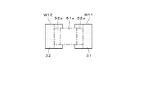
図3は、チップ部品に対する検査用ウィンドウの設定例を示す。図中、W11,W12は、はんだ検査のためのウィンドウであって、基板上のランドを含むように設定される。以下、このウィンドウW11,W12を「ランドウィンドウW11,W12」という。また、W2は、部品の欠落や位置ずれなどを検査するためのウィンドウであって、以下、これを「部品ウィンドウW2」という。
さらに、前記ランドウィンドウW11,W12や部品ウィンドウW2を含む第3の検査用ウィンドウW3が設定される。このウィンドウW3は、ランドウィンドウW11,W12や部品ウィンドウW2を位置決めする際の基準となるもので、以下、これを「基準ウィンドウW3」という。
FIG. 3 shows an example of setting an inspection window for a chip component. In the figure, W11 and W12 are windows for solder inspection, and are set so as to include lands on the board. Hereinafter, the windows W11 and W12 are referred to as “land windows W11 and W12”. Further, W2 is a window for inspecting a missing part or a positional deviation of the component, and this is hereinafter referred to as a “component window W2”.
Further, a third inspection window W3 including the land windows W11 and W12 and the component window W2 is set. The window W3 serves as a reference for positioning the land windows W11 and W12 and the component window W2. Hereinafter, this window is referred to as a “reference window W3”.
各検査用ウィンドウW11,W12,W2,W3の設定条件を示す情報(ウィンドウの大きさや設定位置など)は、基板の設計データ(CADデータ)と前記ライブラリデータとをリンクさせる制御部11の処理により、自動的に作成される。CADデータには、各部品の実装位置や実装される部品の識別情報(部品種名や型番など)が含まれており、ライブラリデータも、部品名などの識別情報と各種検査情報とを対応づけた構成をとる。制御部11は、CADデータが示す各部品の実装位置に、それぞれ前記識別情報に基づき実装される部品のライブラリデータを適用して、各検査用ウィンドウW11,W12,W2,W3の具体的な大きさおよび設定位置を定める。ここで定められた検査用ウィンドウW11,W12,W2の大きさや設定位置が、前記設定条件としてティーチングテーブル19に登録されることになる。
Information indicating the setting conditions of the inspection windows W11, W12, W2, and W3 (window size, setting position, and the like) is obtained by processing of the
検査時には、前記登録された設定条件に基づき、各検査用ウィンドウW11,W12,W2,W3を設定した後、基準ウィンドウW3でランドを抽出する。そして、その抽出結果に基づき、前記ランドウィンドウW11,W12や部品ウィンドウW2の設定位置を微調整する。 At the time of inspection, after setting each inspection window W11, W12, W2, W3 based on the registered setting condition, the land is extracted by the reference window W3. Based on the extraction result, the setting positions of the land windows W11 and W12 and the component window W2 are finely adjusted.
なお、ランドの抽出は、ランドの色彩を抽出する2値化処理を実行した後、その2値画像をx,yの各軸方向に投影する処理により行うことができる。または、基準ウィンドウW3内の画像をモノクロ画像に変換してエッジを抽出し、その抽出結果からランドに対応するエッジを抽出するようにしてもよい。 The land can be extracted by performing a binarization process for extracting the color of the land, and then projecting the binary image in the x and y axis directions. Alternatively, the image in the reference window W3 may be converted into a monochrome image to extract an edge, and the edge corresponding to the land may be extracted from the extraction result.
各検査用ウィンドウW11,W12,W2が設定されると、これらのウィンドウ毎にそれぞれ登録された検査情報に基づく検査を実行する。なお、前記部品ウィンドウW2については、従来と同様に、前記2値化しきい値を用いて部品の色彩パターンを抽出し、そのパターンの面積や重心などの特徴量を用いた検査を実行する。よって、以下では、ランドウィンドウW11,W12で実行されるフィレット検査について、詳細な説明を展開することにする。 When each inspection window W11, W12, W2 is set, an inspection based on the inspection information registered for each of these windows is executed. For the component window W2, as in the prior art, a color pattern of a component is extracted using the binarized threshold value, and an inspection using a feature quantity such as the area and the center of gravity of the pattern is executed. Therefore, in the following, a detailed description of the fillet inspection executed in the land windows W11 and W12 will be developed.
フィレットを検査する場合には、図4に示すように、各ランドウィンドウW11,W12内の画像のうち、部品電極52aの端縁からランドウィンドウW11,12の外側端縁までの範囲(図中、網点を付した範囲)を処理対象とする。以下、この網点の範囲に対応する領域31,32を「検査領域31,32」という。なお、この図4では、つぎの図5にならって、チップ部品の部品本体の画像を51aとし、電極の画像を52aとしている。
When inspecting the fillet, as shown in FIG. 4, in the images in the land windows W11 and W12, the range from the edge of the
図5は、チップ部品のはんだフィレットについて、画像上に現れる色彩の分布状態(上段)と実際の形状を側方から見た状態(下段)とを対応づけて示す。なお、この図5では、部品本体を51、電極を52、フィレットを53とし、これらの画像を51a,52a,53aとして示す。 FIG. 5 shows the distribution state of the color appearing on the image (upper stage) and the state when the actual shape is viewed from the side (lower stage) with respect to the solder fillet of the chip part. In FIG. 5, the component main body is 51, the electrode is 52, the fillet is 53, and these images are shown as 51a, 52a, and 53a.
図5(A)は、フィレット53の形状が良好な場合の例である。この場合のフィレット53では、部品51に近い部分が急斜面、基板1に近い部分が平坦面、両者の中間部が暖傾斜面となるから、画像上の色彩は、フィレット53aの下端から上端に向かう方向PAに沿って、赤、緑、青の順に変化する。一方、図5(B)は、不良な場合の例であって、ぬれ性不良やはんだ過多のために、フィレット53が形成されず、はんだが山状に盛り上がった不良部位54になる。このような不良部位54では、部品51に近い部分が平坦面、基板1に近い部分が急斜面、両者の中間部が暖傾斜面となる。したがって、不良部位の画像54aの色彩は、良品の場合とは逆の方向、すなわち上端から下端に向かう方向PBに沿って、赤、緑、青の順に変化することになる。
FIG. 5A shows an example where the shape of the
このように、画像上のはんだ付け部位の赤、緑、青の色彩の分布状態は、はんだの傾斜状態によって異なるものとなる。ただし、いずれの場合にも、傾斜面の勾配が小さい方から大きい方に向かって、赤、緑、青の順に色彩が変化する。この変化は、色相環に沿った変化と同様である。 As described above, the distribution state of red, green, and blue colors of the soldered portion on the image varies depending on the inclination state of the solder. However, in any case, the color changes in the order of red, green, and blue from the smaller gradient of the inclined surface to the larger gradient. This change is the same as the change along the hue circle.
したがって、前記検査領域31,32内の各画素につき、それぞれ赤みが強くなるほど小さくなり、青みが強くなるほど大きくなるように値が変化する1次元の色相データを求め、各方向における色相データの変化量を算出すると、前記図5の方向PA,PBのように、赤、緑、青の順に色彩が変化する方向では、この変化量は所定値以上の大きさを持つものになる。これに対し、上記のような色彩の変化が現れていない方向では、色相の変化量は前記所定値より小さくなる。また、青、緑、赤の順に色彩が変化する方向では、前記色相の変化量はマイナス値になると考えることができる。
Accordingly, for each pixel in the
そこで、この実施例では、赤の側から青の側への色相の変化が現れる方向を示すベクトルを色合い変化ベクトルと定義して、前記1次元の色相データを用いて色合い変化ベクトルを抽出し、このベクトルの大きさや方向を用いてフィレットの良否を判別するようにしている。 Therefore, in this embodiment, a vector indicating the direction in which the hue change from the red side to the blue side appears is defined as a hue change vector, and the hue change vector is extracted using the one-dimensional hue data, Whether the fillet is good or bad is determined using the magnitude and direction of the vector.
前記画像処理部15は、前記色合い変化ベクトルの抽出のために、検査領域31,32内の各画素につき、それぞれR,G,Bの各階調データから成る3次元の画像データを1次元の色相データHに変換する。この変換処理では、R,G,Bの値を相互に比較し、これらの中の最大値VmaxがR,G,Bのいずれであるかによって、下記の(1)(2)(3)式のいずれかを選択して演算を実行する。なお、(1)〜(3)式中のrr,bb,ggは、それぞれ(4)(5)(6)式により求められる。また、(4)〜(6)において、VminはR,G,Bの中の最小値である。
In order to extract the hue change vector, the
R=Vmaxのとき H=(bb−gg)*π/3 ・・・(1)
G=Vmaxのとき H=2+(rr−bb)*π/3 ・・・(2)
B=Vmaxのとき H=4+(gg−rr)*π/3 ・・・(3)
When R = V max H = (bb−gg) * π / 3 (1)
When G = V max H = 2 + (rr−bb) * π / 3 (2)
When B = V max H = 4 + (gg−rr) * π / 3 (3)
rr=(Vmax−R)/(Vmax−Vmin) ・・・(4)
gg=(Vmax−G)/(Vmax−Vmin) ・・・(5)
bb=(Vmax−B)/(Vmax−Vmin) ・・・(6)
rr = (V max -R) / (V max -V min) ··· (4)
gg = (V max -G) / (V max -V min) ··· (5)
bb = (V max -B) / (V max -V min) ··· (6)
R,G,Bが256階調(8ビット)で表されるものとすると、上記の演算による色相データHの値は、理論的には0〜(4+π/3)の範囲で変化する(R=255、G=B=0のときにHは最小値の0になり、R=G=0、B=255のときにHは最大値の4+π/3になる。)。
さらに、この実施例では、この数値変化の範囲が0〜10になるように、下記の(7)式を用いてHの値を補正するようにしている。
H1=H*10/(4+π/3) ・・・(7)
Assuming that R, G, and B are represented by 256 gradations (8 bits), the value of the hue data H obtained by the above calculation theoretically changes in the range of 0 to (4 + π / 3) (R When H = 255 and G = B = 0, H becomes the
Further, in this embodiment, the value of H is corrected using the following equation (7) so that the range of the numerical change is 0-10.
H1 = H * 10 / (4 + π / 3) (7)
上記の色相データH,H1は、赤みが強くなるほど小さくなり、青みが強くなるほど大きくなる。したがって、検査領域31,32において、前記色相データH1に所定のしきい値を上回る変化が現れている場合には、その変化の方向を色合い変化ベクトルの方向として設定することができる。
The above hue data H and H1 become smaller as the redness becomes stronger, and becomes larger as the blueness becomes stronger. Therefore, in the
この実施例では、上記の原理に基づき、図6に示すような手順で色合い変化ベクトルを抽出するようにしている。以下、この図6の処理の内容を、図7〜13に示す具体例を参照しながら、詳細に説明する。なお、図6では、各ステップをST101〜107の符号により示している。以下の説明でも、これにならって「ステップ」を「ST」と略す。また、図7〜13では、左から右に向かう方向をx軸の正方向、下から上に向かう方向をy軸の正方向とし、部品の横幅方向がx軸方向に沿っているものとする。 In this embodiment, based on the above principle, a hue change vector is extracted by a procedure as shown in FIG. Hereinafter, the contents of the processing in FIG. 6 will be described in detail with reference to the specific examples shown in FIGS. In addition, in FIG. 6, each step is shown with the code | symbol of ST101-107. In the following description, “step” is also abbreviated as “ST”. 7 to 13, the direction from left to right is the positive direction of the x-axis, the direction from bottom to top is the positive direction of the y-axis, and the horizontal direction of the component is along the x-axis direction. .
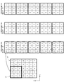
図7は、前記チップ部品51に対する右側のランドウィンドウW11内に設定された検査領域31における前記色相データH1の算出例を示している。説明を簡単にするために、この例では、検査領域31の大きさを、x軸方向に5画素、y軸方向に7画素としている。
FIG. 7 shows an example of calculation of the hue data H1 in the
図6の色合い変化ベクトルの抽出処理では、まず最初のST101において、図8に示すような3画素×3画素のマスクMを前記検査領域の左上端に初期設定する。以下、このマスクM内の9つの画素gを、行・列の関係に基づき座標(i,j)(i,j=1,2,3)で表すものとする。また各画素gについても、それぞれの座標を用いて画素gijと記す。 In the process of extracting the hue change vector in FIG. 6, first, in ST101, a 3 × 3 pixel mask M as shown in FIG. 8 is initially set at the upper left corner of the inspection area. Hereinafter, the nine pixels g in the mask M are represented by coordinates (i, j) (i, j = 1, 2, 3) based on the row / column relationship. Each pixel g is also referred to as a pixel g ij using the respective coordinates.
つぎのST102では、マスクM内の各画素gijについて、それぞれ中央の画素g22との間の色相データの差(gij−g22)を算出する。これらのうち、画素g22同士の演算結果以外の値は、前記画素g22から見た周囲8方向における色相の変化量を表すものとなる。各画素gij毎に得た算出値は、それぞれマスクMにおけるその画素の座標(i,j)に対応づけてメモリ13に保存される。
In the next ST102, for each pixel g ij in the mask M, a difference (g ij −g 22 ) in hue data from the center pixel g 22 is calculated. Of these, values other than the operation result between the pixel g 22 becomes to represent the color variation in the surrounding eight directions as viewed from the pixel g 22. The calculated value obtained for each pixel g ij is stored in the
以下、マスクMが検査領域31の右下に位置合わせされるまで、マスクMを1画素ずつ移動させながら、各位置において前記色相の変化量を算出する処理を実行する(ST102〜104)。 Subsequently, the process of calculating the hue change amount at each position is performed while moving the mask M pixel by pixel until the mask M is aligned with the lower right of the inspection region 31 (ST102 to ST104).
図9は、前記図7に示したデータ構成の検査領域31に前記マスクMを走査した場合に、各位置において前記マスクMから抽出された色相データの構成を示す。なお、以下では、マスクMがy軸方向に沿って走査されるものとして、マスクMを検査領域31の左側端縁に合わせて行う走査を「1列目の走査」といい、マスクMを1画素右にずらして行う走査を「2列目の走査」といい、マスクMをさらに1画素右にずらして行う走査を「3列目の走査」という。
FIG. 9 shows a configuration of hue data extracted from the mask M at each position when the mask M is scanned on the
図10は、前記1列目の走査において、前記マスクMにより抽出された色相データに前記ST102の処理を実行した結果を示したものである。図11は2列目の走査について、図12は3列目の走査について、それぞれ図10と同様の処理結果を示したものである。 FIG. 10 shows the result of performing the process of ST102 on the hue data extracted by the mask M in the scanning of the first column. FIG. 11 shows the same processing results as FIG. 10 for the second row scanning, and FIG. 12 shows the same processing results for FIG.
このように、マスクMを1画素ずつ動かしながら、各位置においてST102を実行することにより、前記8方向毎の色相の変化量を表すデータ配列が15組抽出されることになる。最終位置における処理が終了すると、ST103が「YES」となってST105に進み、前記色相の変化量について方向毎に平均値を求める処理が実行される。 In this way, by executing ST102 at each position while moving the mask M pixel by pixel, 15 sets of data arrays representing hue change amounts in the eight directions are extracted. When the process at the final position is completed, ST103 is “YES”, the process proceeds to ST105, and a process for obtaining an average value for each direction of the hue change amount is executed.
ST105では、具体的には、前記15組のデータ配列に含まれるデータを、それぞれマスクMにおける相対座標が同じ画素毎にまとめて平均値Iijを算出する。たとえば、前記マスクの左上端の画素g11について言えば、各走査位置で画素g11につき求めた変化量(1列目の−1,+1,+1,+2,+2、2列目の−1,+1,+2,+4,+5、3列目の+1,+2,+1,+3,+4)の平均値I11を求めることにより、+1.8という値を得ることができる。他の画素g12〜g33についても、同様にして、平均値I12〜I33が求められる。 In ST105, specifically, the average value I ij is calculated by grouping data included in the 15 sets of data arrays for each pixel having the same relative coordinate in the mask M. For example, regarding the pixel g 11 at the upper left corner of the mask, the amount of change obtained for the pixel g 11 at each scanning position (−1, +1, +1, +2, +2 in the first column, −1, + 1, + 2, + 4, + 5,3 row + 1, + 2, + 1, + 3, by obtaining the average value I 11 of + 4), it is possible to obtain a value of + 1.8. Similarly, average values I 12 to I 33 are obtained for the other pixels g 12 to g 33 .
図13は、前記15組のデータ配列から前記ST105の処理により求めた平均値Iijの算出結果を示す。この結果によれば、中央の画素g22より左側の画素g11,g21,g31における平均値I11,I21,I31が正になっているとともに、画素g22より右側の画素g13,g23,g33における平均値I13,I23,I33は負になっている。よって、色合い変化ベクトルは、x軸の負の方向を向いているものと推測することができる。
FIG. 13 shows the calculation result of the average value I ij obtained by the process of ST105 from the 15 sets of data arrays. According to this result, the average values I 11 , I 21 , I 31 in the pixels g 11 , g 21 , g 31 on the left side of the central pixel g 22 are positive, and the pixel g on the right side of the pixel g 22 is positive. 13, the
図6の処理では、色合い変化ベクトルを特定するために、さらに以下のような処理を実行する。まず、ST106において、前記ST105で算出された各平均値Iijを用いて、x軸方向およびy軸方向における色相の変化量Cx,Cyを算出する。この算出処理は、濃淡画像のエッジ抽出処理に用いられるソーベルフィルタを応用した演算により行われる。具体的には下記の(8)(9)式が使用される。 In the process of FIG. 6, the following process is further executed in order to specify the hue change vector. First, in ST 106, using the average value I ij calculated in the ST105, the amount of change in hue in the x axis direction and y axis direction Cx, calculates the Cy. This calculation process is performed by calculation using a Sobel filter used for edge extraction processing of a grayscale image. Specifically, the following formulas (8) and (9) are used.
Cx=(I13+2I23+I33)−(I11+2I21+I31) ・・・(8)
Cy=(I11+2I12+I13)−(I31+2I32+I33) ・・・(9)
Cx = (I 13 + 2I 23 + I 33 ) − (I 11 + 2I 21 + I 31 ) (8)
Cy = (I 11 + 2I 12 + I 13 ) − (I 31 + 2I 32 + I 33 ) (9)
上記の変化量CxおよびCyは、検査領域において、色相データが増加に向かう方向およびその変化量を、x,yの各軸に分解して示したものと考えることができる。よって、ST107では、これらCx,Cyが示すベクトルを合成したものを色合い変化ベクトルとして、このベクトルの長さおよび方向をCx,Cyから算出するようにしている。 The above-described change amounts Cx and Cy can be considered as the direction in which the hue data increases and the change amount in the inspection region are decomposed into the x and y axes. Therefore, in ST107, a combination of the vectors indicated by Cx and Cy is used as a hue change vector, and the length and direction of this vector are calculated from Cx and Cy.
ST107では、前記CxおよびCyにより表される2つのベクトルの合成ベクトルの長さおよび方向を算出する処理を実行する。この実施例では、合成ベクトルの方向を、x軸の正方向に対してベクトルがなす角度θとして定義し、Cx,Cyの値に応じて下記の(A)〜(E)式のいずれかを用いて算出するようにしている。また、ベクトルの長さは(F)式により求められる。
Cx>0およびCy≧0のとき
θ=tan−1(Cy/Cx)・・・(A)
Cx>0およびCy<0のとき
θ=tan−1(Cy/Cx)+360 ・・・(B)
Cx<0のとき θ=tan−1(Cy/Cx)+180 ・・・(C)
Cx=0およびCy>0のとき θ=0 ・・・・・(D)
Cx=0およびCy<0のとき θ=180 ・・・(E)
In ST107, processing for calculating the length and direction of the combined vector of the two vectors represented by Cx and Cy is executed. In this embodiment, the direction of the combined vector is defined as an angle θ formed by the vector with respect to the positive direction of the x axis, and any one of the following formulas (A) to (E) is set according to the values of Cx and Cy. It is made to calculate using. Moreover, the length of a vector is calculated | required by (F) Formula.
When Cx> 0 and Cy ≧ 0
θ = tan −1 (Cy / Cx) (A)
When Cx> 0 and Cy <0
θ = tan −1 (Cy / Cx) +360 (B)
When Cx <0 θ = tan −1 (Cy / Cx) +180 (C)
When Cx = 0 and Cy> 0, θ = 0 (D)
When Cx = 0 and Cy <0, θ = 180 (E)
![]()
![]()
前記図13に示した平均値の算出例の場合、上記の(8)(9)式から、Cx=−17.11、Cy=0.07となる。すなわち、赤の側から青の側に向かう色相の変化は、x軸方向においては負の方向(図の左側)を向くベクトルにより表され、y軸方向においては正の方向(図の上側)を向くベクトルにより表されると、考えることができる。 In the case of the average value calculation example shown in FIG. 13, Cx = −17.11 and Cy = 0.07 from the above equations (8) and (9). That is, the change in hue from the red side to the blue side is represented by a vector pointing in the negative direction (left side in the figure) in the x-axis direction, and a positive direction (upper side in the figure) in the y-axis direction. It can be thought of as being represented by a facing vector.
さらに、上記のCxおよびCyの値を用いてST107を実行した場合、合成ベクトルの角度θの算出については、(C)が適用されることから、θ=179.77°となる。また、ベクトルの長さDについては、(F)式により、D=17.11となる。
この算出結果によれば、前記した推論どおり、色合い変化ベクトルは、x軸の負の方向を向いていることになる。
Further, when ST107 is executed using the above-described values of Cx and Cy, (C) is applied to the calculation of the angle θ of the combined vector, and θ = 179.77 °. The vector length D is D = 17.11 according to the equation (F).
According to this calculation result, as described above, the hue change vector is oriented in the negative direction of the x axis.
前記図7に示した検査領域31は、部品の右側のランドウィンドウW11に設定されたものであるから、色合い変化ベクトルの望ましい方向は、前記図5に示した方向PA、すなわちx軸の負の方向となる。上記の演算結果によれば、例示の検査領域31から抽出された色合い変化ベクトルの方向は前記望ましい方向PAに適合しており、前記検査領域31には、良好な状態のフィレットが存在すると考えることができる。
Since the
この実施例のフィレット検査では、ランドウィンドウW11,W12内にそれぞれ検査領域31,32を設定し、これらの検査領域31,32毎に上記の色合い変化ベクトルの抽出処理を実行した後、抽出されたベクトルの方向をあらかじめ登録された基準の方向と比較する。ただし、いずれかの検査領域において抽出された色合い変化ベクトルの大きさが所定のしきい値より小さい場合には、その検査領域内には、赤から青の方向への色相変化は現れていないものとみなす。言い換えれば、検査領域内には、フィレットに該当する傾斜面が含まれていないということになる。
In the fillet inspection of this embodiment, the
図14は、前記色合い変化ベクトルの基準の方向の教示例を示す。この例では、作業者が、画像上で赤,緑,青の順に色彩が変化している方向を視認しながら、ランドの端縁部から部品の中央部Cに向けてカーソルを移動する操作を行うことによって、そのカーソルの移動方向(図中、矢印f,kで示す。)を基準の方向として指定するようにしている。指定された方向f,kは、それぞれx軸の正の方向に対する角度に変換され、前記ティーチングテーブル19に登録される。 FIG. 14 shows a teaching example of the reference direction of the hue change vector. In this example, the operator moves the cursor from the edge of the land toward the center C of the component while visually confirming the direction in which the color changes in the order of red, green, and blue. By doing so, the direction of movement of the cursor (indicated by arrows f and k in the figure) is designated as the reference direction. The designated directions f and k are converted into angles with respect to the positive direction of the x axis, respectively, and are registered in the teaching table 19.
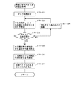
図15は、前記基板検査装置における検査の手順を示す。この手順の実行に先立ち、係員は、前記入力部22を用いて被検査基板1Tの基板名などを入力する作業を行っており、これに応じて、被検査基板1Tに対応する判定ファイルが読み出されてメモリ13にセットされ、図15の手順がスタートする。なお、この手順は、1枚の被検査基板1Tに対して行われるもので、被検査基板1Tの数に応じて繰り返されることになる。なお、この図15では、処理の開始をST1とする。
FIG. 15 shows an inspection procedure in the substrate inspection apparatus. Prior to the execution of this procedure, the clerk performs an operation of inputting the board name of the
ST1では、被検査基板1TがY軸テーブル部7に搬入され、撮像部3による撮像が開始される。つぎに、制御部11は、前記判定ファイル内の位置決めデータに基づき、被検査基板1Tに撮像部3および投光部4を位置合わせして、前記基板1Tの画像を生成する。そして、生成された画像上の各部品に検査用ウィンドウW11,W12,W2,W3を設定する。
In ST1, the inspected
つぎのST3では、最初の検査対象部品につき、前記基準ウィンドウW3内で両側のランドを抽出する処理を行い、その抽出結果に応じてランドウィンドウW11,W12の位置を補正する。つぎのST4では、この部品について、フィレットの検査を実行するかどうかをチェックする。この判定が「YES」であれば、以下、ST5〜9を順に実行する。 In the next ST3, for the first part to be inspected, a process of extracting lands on both sides in the reference window W3 is performed, and the positions of the land windows W11 and W12 are corrected according to the extraction result. In the next ST4, it is checked whether or not to perform a fillet inspection for this part. If this determination is “YES”, then ST5 to ST9 are executed in order.
なお、このST5〜9は、2つのランドウィンドウW11,W12毎に個別に行われるものであるが、以下では、説明を簡単にするために、ランドウィンドウW11のみを処理対象にして説明する。また、この説明でも、部品の横幅方向がx軸方向に沿っているものとする。 Note that ST5 to 9 are individually performed for each of the two land windows W11 and W12. However, for the sake of simplicity, only the land window W11 will be described below as a processing target. Also in this description, it is assumed that the horizontal width direction of the component is along the x-axis direction.
まず、ST5では、前記ランドウィンドウW11において、前記部品の電極とフィレットとの境界位置を抽出する処理を実行する。この処理のために、前記判定ファイルには、あらかじめ、電極の画像の色彩(一般に赤みが強い色彩である。)を抽出するための2値化しきい値(R,G,B毎に設定される。)や、電極の縦幅の長さに相当する画素数が登録される(これらのデータも前記ライブラリデータから転用することができる。)。ST5では、ランドウィンドウW11内の画像を前記2値化しきい値により2値化した後、ランドウィンドウW11の内側(部品の側)から外側に向かう方向をサーチ方向として、そのサーチ方向に直交するラインに順に着目しつつ、前記電極の色彩が前記縦幅の長さに相当する画素数分連なっているラインを抽出する。ここで電極の色彩が現れているラインが抽出される状態から抽出されない状態に移行したときのサーチ位置のx座標を、前記電極とフィレットとの境界位置として認定する。 First, in ST5, processing for extracting a boundary position between the electrode of the component and the fillet is executed in the land window W11. For this processing, the determination file is set in advance for each of the binarization threshold values (R, G, B) for extracting the color of the electrode image (generally a color with a strong redness). Or the number of pixels corresponding to the vertical length of the electrode is registered (these data can also be diverted from the library data). In ST5, after the image in the land window W11 is binarized by the binarization threshold value, the direction from the inner side (part side) to the outer side of the land window W11 is set as the search direction, and the line is orthogonal to the search direction. The lines in which the colors of the electrodes are continuous for the number of pixels corresponding to the length of the vertical width are extracted. Here, the x-coordinate of the search position when the line where the color of the electrode appears is shifted from the extracted state to the non-extracted state is recognized as the boundary position between the electrode and the fillet.
このようにして、電極とフィレットとの境界位置が抽出されると、つぎのST6では、その抽出された境界位置からランドウィンドウW11の外側端縁までの範囲に検査領域31を設定する。続くST7では、設定された検査領域31内の各画素につき、それぞれ前記(1)〜(7)式を用いて色相データH1を求める。ST8では、画素毎の色相データH1を用いて、検査領域31における色合い変化ベクトルを抽出する処理を実行する。このST8では、前記図6に示した一連の処理が実行されるもので、色合い変化ベクトルの方向を表す角度θおよび長さDが算出される。
When the boundary position between the electrode and the fillet is thus extracted, in the next ST6, the
つぎのST9では、抽出された色合い変化ベクトルを用いて、フィレットが形成されているか否かやそのフィレットの傾斜面の良否を判別する。
この判別処理では、まず色合い変化ベクトルの長さDを所定のしきい値(前記(F)式の場合、10程度にするとよい。)と比較する。この比較において、前記長さDがしきい値以上であれば、前記角度θをあらかじめ登録された基準の角度と比較する。そして基準の角度に対する前記角度θの差が所定のしきい値(たとえば10°)以内であれば、フィレットは良好に形成されていると判断する。他方、前記角度差が前記しきい値を上回る場合には、フィレットの傾斜状態は不適であると判断する。また、前記ベクトルの長さDがしきい値を下回る場合には、検査領域31にはフィレットに該当する傾斜面は含まれていないと判断する。
In the next ST9, it is determined whether or not a fillet is formed and the quality of the inclined surface of the fillet using the extracted hue change vector.
In this discrimination process, first, the length D of the hue change vector is compared with a predetermined threshold value (in the case of the formula (F), it may be about 10). In this comparison, if the length D is equal to or greater than a threshold value, the angle θ is compared with a reference angle registered in advance. If the difference of the angle θ with respect to the reference angle is within a predetermined threshold (for example, 10 °), it is determined that the fillet is well formed. On the other hand, if the angle difference exceeds the threshold value, it is determined that the tilted state of the fillet is inappropriate. If the vector length D is less than the threshold value, it is determined that the
このようにしてフィレットの検査が終了すると、ST10に進み、その他の検査(部品の有無や位置ずれなど)を実行する。この検査については、従来と同様であるので、詳細は省略する。 When the fillet inspection is completed in this way, the process proceeds to ST10, and other inspections (such as the presence / absence of parts and positional deviation) are performed. Since this inspection is the same as the conventional one, the details are omitted.
以下、同様にして,画像上の各部品に対する検査を順に実行する。各部品に対する判別結果は、メモリ13に一時保存される。また、1画面分の検査が終了すると、前記X軸テーブル部6やY軸テーブル部7を動かして撮像部3の視野を変更し、再度撮影を行って、得られた画像上の部品について、同様の検査を実行する。
Thereafter, in the same manner, the inspection for each part on the image is sequentially executed. The determination result for each component is temporarily stored in the
すべての部品に対する処理が終了すると、ST11が「YES」となってST12に進み、前記メモリ13に保存された判別結果に基づき、不良と判別された部位があったか否かを判別する。ここで不良部位があると判別すると、ST13に進んで、被検査基板1Tは不良であると判定する。他方、いずれの部品についても良判定が得られている場合には、ST14に進み、前記被検査基板1Tは良品であると判定する。この後は、ST15に進み、前記判定結果を出力して処理を終了する。
When the processing for all the parts is completed, ST11 becomes “YES”, and the process proceeds to ST12. Based on the determination result stored in the
なお、上記の実施例では、ティーチング時には、作業者の操作に応じて色合い変化ベクトルの基準方向を登録するものとしたが、これに限らず、検査時と同様の処理によってランドウィンドウW11,W12内の色合い変化ベクトルを抽出し、その抽出結果を登録するようにしてもよい。この場合には、検査時に抽出された色合い変化ベクトルと登録された色合い変化ベクトルとの間で、方向および長さを比較することができる。 In the above embodiment, at the time of teaching, the reference direction of the hue change vector is registered according to the operation of the operator. However, the present invention is not limited to this, and the land windows W11 and W12 are processed by the same processing as that at the time of inspection. May be extracted, and the extraction result may be registered. In this case, the direction and length can be compared between the hue change vector extracted at the time of inspection and the registered hue change vector.
さらに、ティーチング時に、色合い変化ベクトルの抽出位置を登録するようにしてもよい。この場合、検査時の色合い変化ベクトルの抽出位置を登録された位置と比較することによって、フィレットの位置ずれを検出することが可能である。 Further, the extraction position of the hue change vector may be registered during teaching. In this case, it is possible to detect the misalignment of the fillet by comparing the extracted position of the hue change vector at the time of inspection with the registered position.
さらに、この色合い変化ベクトルによれば、基板上に複数の同一部品が実装される場合、そのうちの1つの部品について色合い変化ベクトルの基準方向を登録すれば、他の部品にもその登録データを転用することができる。前記したように、同一部品であっても、その周辺の実装密度によってフィレットの傾斜角度が異なる可能性があるが、色合い変化ベクトルの方向は変動しない。したがって、同一部品間におけるフィレットの傾斜角度にばらつきがあっても、共通の検査情報を使用することが可能になり、ティーチングにおける効率を向上することができる。また、ランドが小さいために急峻になり、2値化処理では青色領域しか抽出されないようなフィレットについても、色合い変化ベクトルならば、その勾配の変化の方向を抽出することが可能になるから、フィレット検査の精度を大幅に高めることができる。
なお、色合い変化ベクトルの基準方向は、ライブラリデータとして登録しておくこともできる。
Further, according to the color change vector, when a plurality of identical components are mounted on the board, if the reference direction of the color change vector is registered for one of the components, the registered data is transferred to other components. can do. As described above, even if the parts are the same, the inclination angle of the fillet may be different depending on the peripheral mounting density, but the direction of the hue change vector does not change. Therefore, even if there is a variation in the inclination angle of the fillet between the same parts, it is possible to use common inspection information and improve the efficiency in teaching. Also, for a fillet that is steep due to the small land and only the blue region is extracted in the binarization process, the direction of the gradient change can be extracted with the hue change vector. Inspection accuracy can be greatly increased.
The reference direction of the hue change vector can be registered as library data.
また、上記の実施例で使用した色相データH1は、着目する画素の色彩が色相環の赤から青までの範囲のどの位置に相当するかを示すものであるが、これに代えて、たとえば青色光源に対応する階調データBについて、下記(10)式による色相データbを求めてもよい。 Further, the hue data H1 used in the above embodiment indicates which position in the range of the hue circle from red to blue corresponds to the color of the pixel of interest. For the gradation data B corresponding to the light source, the hue data b according to the following equation (10) may be obtained.

上記(10)式による色相データbは、画素の明度を決定する色成分のうちの青色成分の割合を示すものである。この色相データbも、前記色相データH1と同様に、青みが強くなるほど大きくなり、赤みが強くなるほど小さくなるから、先の実施例と同様の方法で色合い変化ベクトルを設定し、そのベクトルの方向からフィレットの傾斜方向を判別することができる。 The hue data b according to the above equation (10) indicates the ratio of the blue component of the color components that determine the brightness of the pixel. Similarly to the hue data H1, the hue data b becomes larger as the bluish color becomes stronger and becomes smaller as the reddish color becomes stronger. Therefore, a hue change vector is set in the same manner as in the previous embodiment, and the direction of the vector is determined. The inclination direction of the fillet can be determined.
さらにこの実施例では、異なる色彩光を発光する光源8,9,10を使用してカラー画像を処理するようにしたが、これに代えて、これらの光源8,9,10を白色光源にしてモノクロカメラで撮像する場合にも、上記した実施例と同様の処理を実行することが可能である。
たとえば、最初に光源8を点灯させて撮像し、得られた濃淡画像データをRの階調データとみなしてメモリ13に一時保存する。次に光源9を点灯させて撮像し、得られた濃淡画像データをGの階調データとみなしてメモリ13に一時保存する。最後に光源10を点灯させて撮像し、得られた濃淡画像データをBの階調データとみなしてメモリ13に一時保存する。このように、順に取得した3枚の濃淡画像データを、それぞれをR,G,Bの階調データとして取り扱い、上記した実施例を適用して色合い変化ベクトルの抽出処理を実行する。この方法によれば、画像データの生成に必要な時間は長くなるが、その後は、カラー画像を使用する場合と同様のアルゴリズムでフィレットの検査を実行することができる。
Furthermore, in this embodiment, the color images are processed using the
For example, the
1T 被検査基板
3 撮像部
4 投光部
5 制御処理部
8,9,10 光源
11 制御部
15 画像処理部
18 検査部
19 ティーチングテーブル
23 CRT表示部
25 送受信部
26 外部メモリ装置
1T Board to be inspected 3
Claims (10)
前記画像中の検査対象物を含む検査領域を設定し、
前記検査領域内の複数の画素につき、それぞれ各光源の配列に対応する色相の変化の方向に沿って増加する1次元の色相データを算出するための演算式に当該画素の画像データをあてはめて、前記色相データを算出する第1のステップと、
前記第1のステップの算出結果を用いて、前記検査領域において、前記色相データの変化量が所定のしきい値以上になる方向を抽出し、その抽出した方向を前記各光源の配列に対応した色相の変化が生じている方向として特定する第2のステップと、
前記第2のステップで特定された方向をあらかじめ設定された基準の方向と比較する第3のステップと、
前記第3のステップにおける比較結果に基づき、前記検査対象物の表面状態の良否を判別する第4のステップとを、実行することを特徴とする表面状態検査方法。 A plurality of light sources that emit different colored lights are arranged and illuminated with respect to an inspection object having an inclined surface on the surface so as to have different elevation angles as viewed from the arrangement position of the inspection object, and the arrangement of the inspection object In the method of inspecting the surface state of the inspection object using a color image obtained by an imaging means installed above the position,
Set an inspection area including the inspection object in the image ,
For a plurality of pixels in the inspection region, the image data of the pixel is applied to an arithmetic expression for calculating one-dimensional hue data that increases along the direction of hue change corresponding to each light source array, A first step of calculating the hue data;
Using the calculation result of the first step, a direction in which the amount of change in the hue data is equal to or greater than a predetermined threshold is extracted in the inspection region, and the extracted direction corresponds to the arrangement of the light sources. A second step that identifies the direction in which the hue change is occurring;
A third step of comparing the direction identified in the second step with a preset reference direction;
A surface condition inspection method, comprising: performing a fourth step of determining whether the surface condition of the inspection object is good or not based on a comparison result in the third step.
前記第1のステップでは、色相環上の各光源の配列に対応する範囲における処理対象の画素の色相の位置を求める演算式を用いて、処理対象の画素の色相データを算出する請求項1に記載された表面状態検査方法。 The plurality of light sources are arranged so that the respective emission colors are arranged along the direction of hue change on the hue ring with respect to the inspection object,
In the first step, the hue data of the pixel to be processed is calculated using an arithmetic expression for obtaining the hue position of the pixel to be processed in a range corresponding to the arrangement of the light sources on the hue circle. The surface condition inspection method described.
前記検査対象物の配置位置の上方に配備された撮像手段と、
前記照明手段の各光源を点灯させた状態で前記撮像手段により生成された画像を取り込む画像入力手段と、
前記画像入力手段が入力した画像中の検査対象物を含む領域を設定する領域設定手段と、
前記領域設定手段により設定された検査領域内の複数の画素につき、それぞれ各光源の配列に対応する色相の変化の方向に沿って増加する1次元の色相データを算出するための演算式に当該画素の画像データをあてはめて、前記色相データを算出する色相データ算出手段と、
前記色相データ算出手段による演算の結果を用いて、前記検査領域において、前記色相データの変化量が所定のしきい値以上になる方向を抽出し、その抽出された方向を前記各光源の配列に対応した色相の変化が生じている方向として特定する方向特定手段と、
前記検査対象物の表面状態が良好であるときに前記方向特定手段により特定されるべき方向を、基準の方向として登録する登録手段と、
前記方向特定手段により特定された方向を、前記登録手段により登録された基準の方向と比較して、前記検査対象物の表面状態の良否を判別する判別手段と、
前記判別手段による判別結果を出力する出力手段とを具備して成る表面状態検査装置。 Illumination means comprising a plurality of light sources that emit different color lights and arranged such that the elevation angles when viewed from the arrangement position of the inspection object are different,
Imaging means arranged above the position of the inspection object;
An image input means for capturing an image generated by the imaging means in a state where each light source of the illumination means is turned on;
An area setting means for setting an area including an inspection object in the image input by the image input means ;
For a plurality of pixels in the inspection region set by the region setting means, the pixel is used as an arithmetic expression for calculating one-dimensional hue data that increases along the direction of hue change corresponding to each light source array. A hue data calculation means for calculating the hue data by applying the image data of
Using the result of the calculation by the hue data calculation means, a direction in which the change amount of the hue data is equal to or greater than a predetermined threshold is extracted in the inspection region, and the extracted direction is used as the array of the light sources. Direction identification means for identifying the direction in which the corresponding hue change occurs ,
A registration means for registering a direction to be specified by the direction specifying means when the surface condition of the inspection object is good, as a reference direction ;
A determination means for comparing the direction specified by the direction specifying means with a reference direction registered by the registration means to determine the quality of the surface state of the inspection object;
A surface condition inspection apparatus comprising output means for outputting a discrimination result by the discrimination means.
前記色相データ算出手段は、色相環上の各光源の配列に対応する範囲における処理対象の画素の色相の位置を求める演算式を用いて、処理対象の画素の色相データを算出する請求項5に記載された表面状態検査装置。 The plurality of light sources are arranged so that the respective emission colors are arranged along the direction of hue change on the hue ring with respect to the inspection object,
6. The hue data calculation unit calculates hue data of a pixel to be processed using an arithmetic expression for obtaining a hue position of the pixel to be processed in a range corresponding to the arrangement of each light source on the hue circle. The surface condition inspection device described.
互いに異なる色彩光を発光する複数の光源を検査対象物の配置位置から見た仰角が異なるように配列して成る照明手段と、
前記基板の上方に配備された撮像手段と、
前記照明手段の各光源を点灯させた状態で前記撮像手段により生成された画像を取り込む画像入力手段と、
前記画像入力手段が入力した画像中のはんだ付け部位にそれぞれ個別の検査領域を設定する領域設定手段と、
前記領域設定手段により設定された検査領域毎に、その領域内の複数の画素につき、それぞれ各光源の配列に対応する色相の変化に沿って増加する1次元の色相データを算出するための演算式に当該画素の画像データをあてはめて、前記色相データを算出する色相データ算出手段と、
前記色相データ算出手段による演算の結果を用いて、前記領域設定手段により設定された各検査領域について、それぞれ前記色相データの変化量が所定のしきい値以上になる方向を抽出し、その抽出した方向を各光源の配列に対応した色相の変化が生じている方向として特定する方向特定手段と、
前記各検査領域について、それぞれその領域内のはんだの表面状態が良好であるときに前記方向特定手段により特定されるべき方向を、基準の方向として登録する登録手段と、
前記各検査領域について、それぞれ前記方向特定手段により特定された方向を前記登録手段により登録された基準の方向と比較して、各はんだ付け部位の良否を判別する判別手段と、
前記判別手段による判別結果を出力する出力手段とを具備して成る表面状態検査装置。 An apparatus for inspecting a board on which a plurality of components are soldered,
Illumination means comprising a plurality of light sources that emit different color lights and arranged such that the elevation angles when viewed from the arrangement position of the inspection object are different,
Imaging means disposed above the substrate;
An image input means for capturing an image generated by the imaging means in a state where each light source of the illumination means is turned on;
Area setting means for setting an individual inspection area for each soldering site in the image input by the image input means ;
For each of the inspection areas set by the area setting means, for each of a plurality of pixels in the area, an arithmetic expression for calculating one-dimensional hue data that increases along the hue change corresponding to each light source array Hue data calculation means for calculating the hue data by applying the image data of the pixel to
Using the result of the calculation by the hue data calculation means, for each inspection area set by the area setting means, the direction in which the amount of change in the hue data is equal to or greater than a predetermined threshold is extracted and extracted. Direction specifying means for specifying the direction as a direction in which a hue change corresponding to the arrangement of each light source occurs;
For each inspection area, a registration means for registering the direction to be specified by the direction specifying means when the surface condition of the solder in the area is good, as a reference direction ,
For each of the inspection areas, a determination unit that compares the direction specified by the direction specifying unit with the reference direction registered by the registration unit, and determines the quality of each soldering part;
A surface condition inspection apparatus comprising output means for outputting a discrimination result by the discrimination means.
Priority Applications (4)
| Application Number | Priority Date | Filing Date | Title |
|---|---|---|---|
| JP2005032845A JP3867724B2 (en) | 2004-02-27 | 2005-02-09 | Surface condition inspection method, surface condition inspection apparatus and substrate inspection apparatus using the method |
| US11/056,739 US7505149B2 (en) | 2004-02-27 | 2005-02-11 | Apparatus for surface inspection and method and apparatus for inspecting substrate |
| EP05003164A EP1568985A3 (en) | 2004-02-27 | 2005-02-15 | Apparatus for surface inspection and method and apparatus for inspecting substrate |
| CNB2005100525392A CN1322307C (en) | 2004-02-27 | 2005-02-28 | Apparatus for surface inspection and method and apparatus for inspecting substrate |
Applications Claiming Priority (2)
| Application Number | Priority Date | Filing Date | Title |
|---|---|---|---|
| JP2004052800 | 2004-02-27 | ||
| JP2005032845A JP3867724B2 (en) | 2004-02-27 | 2005-02-09 | Surface condition inspection method, surface condition inspection apparatus and substrate inspection apparatus using the method |
Related Child Applications (1)
| Application Number | Title | Priority Date | Filing Date |
|---|---|---|---|
| JP2006229859A Division JP2006322951A (en) | 2004-02-27 | 2006-08-25 | Method and device for surface condition inspection, and device for inspecting substrate |
Publications (2)
| Publication Number | Publication Date |
|---|---|
| JP2005274558A JP2005274558A (en) | 2005-10-06 |
| JP3867724B2 true JP3867724B2 (en) | 2007-01-10 |
Family
ID=34752167
Family Applications (1)
| Application Number | Title | Priority Date | Filing Date |
|---|---|---|---|
| JP2005032845A Expired - Fee Related JP3867724B2 (en) | 2004-02-27 | 2005-02-09 | Surface condition inspection method, surface condition inspection apparatus and substrate inspection apparatus using the method |
Country Status (4)
| Country | Link |
|---|---|
| US (1) | US7505149B2 (en) |
| EP (1) | EP1568985A3 (en) |
| JP (1) | JP3867724B2 (en) |
| CN (1) | CN1322307C (en) |
Families Citing this family (43)
| Publication number | Priority date | Publication date | Assignee | Title |
|---|---|---|---|---|
| JP4713279B2 (en) * | 2005-08-31 | 2011-06-29 | 第一実業ビスウィル株式会社 | Illumination device and visual inspection apparatus equipped with the same |
| CN100453965C (en) * | 2005-11-08 | 2009-01-21 | 致茂电子股份有限公司 | Conformity interference scan method |
| JP5181321B2 (en) * | 2006-10-20 | 2013-04-10 | シーシーエス株式会社 | Light irradiation device |
| JP2009065146A (en) * | 2007-08-15 | 2009-03-26 | Sony Corp | Method of forming semiconductor thin film, and inspection device for the semiconductor thin film |
| JP5470708B2 (en) * | 2008-01-21 | 2014-04-16 | オムロン株式会社 | Illumination device and defect inspection apparatus using the same |
| US8077307B2 (en) * | 2008-04-09 | 2011-12-13 | Orbotech Ltd. | Illumination system for optical inspection |
| JP2010002216A (en) * | 2008-06-18 | 2010-01-07 | Kobelco Kaken:Kk | Observation device of edge surface |
| JP4719284B2 (en) * | 2008-10-10 | 2011-07-06 | トヨタ自動車株式会社 | Surface inspection device |
| US20100259746A1 (en) * | 2009-04-10 | 2010-10-14 | Omron Corporation | Profilometer |
| US8717578B2 (en) | 2009-04-10 | 2014-05-06 | Omron Corporation | Profilometer, measuring apparatus, and observing apparatus |
| WO2010134232A1 (en) * | 2009-05-21 | 2010-11-25 | 本田技研工業株式会社 | Surface examination device |
| JP2011232279A (en) * | 2010-04-30 | 2011-11-17 | Sony Corp | Tilt inspection device and tilt inspection method |
| KR101033855B1 (en) * | 2010-09-02 | 2011-05-16 | 노바테크 (주) | System of 2d code detection and thickness measurement for glass substrate, and method of the same |
| JP5777570B2 (en) * | 2011-06-24 | 2015-09-09 | 東京エレクトロン株式会社 | Image processing method, image display method, image processing apparatus, program, and computer storage medium |
| US20130120557A1 (en) * | 2011-11-14 | 2013-05-16 | Microscan Systems, Inc. | Part inspection system |
| JP5861462B2 (en) * | 2012-01-17 | 2016-02-16 | オムロン株式会社 | Inspection standard registration method for solder inspection and board inspection apparatus using the method |
| TW201504615A (en) * | 2013-07-31 | 2015-02-01 | Genesis Photonics Inc | Inspection apparatus |
| KR101501129B1 (en) * | 2013-08-23 | 2015-03-12 | 주식회사 고영테크놀러지 | Substrate inspection apparatus |
| JP6116710B2 (en) * | 2014-01-08 | 2017-04-19 | ヤマハ発動機株式会社 | Appearance inspection apparatus and appearance inspection method |
| CN103728306A (en) * | 2014-01-15 | 2014-04-16 | 唐山英莱科技有限公司 | Plain butt weld detection system based on dual-path converged adjustable light path |
| JP6427332B2 (en) * | 2014-04-08 | 2018-11-21 | 株式会社ミツトヨ | Image measuring machine |
| US10533952B2 (en) * | 2014-12-08 | 2020-01-14 | Koh Young Technology Inc. | Method of inspecting a terminal of a component mounted on a substrate and substrate inspection apparatus |
| JP6791631B2 (en) * | 2016-01-06 | 2020-11-25 | 株式会社サキコーポレーション | Image generation method and inspection equipment |
| CN106017322A (en) * | 2016-06-20 | 2016-10-12 | 无锡兴彦影像科技有限公司 | Color three-dimensional imaging device used for circuit board solder paste or patch detection and method |
| KR101739696B1 (en) * | 2016-07-13 | 2017-05-25 | 서장일 | Lighting system of recognizing material of an object and method of recognizing material of an object using the same |
| JP6759812B2 (en) * | 2016-07-29 | 2020-09-23 | オムロン株式会社 | Defect inspection equipment and defect inspection method |
| CN106645161B (en) * | 2016-09-27 | 2020-02-04 | 凌云光技术集团有限责任公司 | Surface defect detection system and method |
| US9835679B1 (en) * | 2016-09-30 | 2017-12-05 | Intel Corporation | Systems, methods, and apparatuses for implementing fast throughput die handling for synchronous multi-die testing |
| US10942257B2 (en) | 2016-12-31 | 2021-03-09 | Innovusion Ireland Limited | 2D scanning high precision LiDAR using combination of rotating concave mirror and beam steering devices |
| JP6733039B2 (en) * | 2017-03-07 | 2020-07-29 | ヤマハ発動機株式会社 | Appearance inspection device, appearance inspection method |
| JP6857079B2 (en) * | 2017-05-09 | 2021-04-14 | 株式会社キーエンス | Image inspection equipment |
| US11493601B2 (en) | 2017-12-22 | 2022-11-08 | Innovusion, Inc. | High density LIDAR scanning |
| CN112292608A (en) | 2018-02-23 | 2021-01-29 | 图达通爱尔兰有限公司 | Two-dimensional steering system for LIDAR system |
| US11808888B2 (en) | 2018-02-23 | 2023-11-07 | Innovusion, Inc. | Multi-wavelength pulse steering in LiDAR systems |
| JP6969439B2 (en) * | 2018-02-23 | 2021-11-24 | オムロン株式会社 | Visual inspection device and lighting condition setting method for visual inspection device |
| JP7017949B2 (en) * | 2018-03-02 | 2022-02-09 | 株式会社ディスコ | Processing equipment |
| JP7087533B2 (en) * | 2018-03-26 | 2022-06-21 | 住友電気工業株式会社 | Surface condition inspection device and surface condition inspection method |
| CN108956462A (en) * | 2018-05-15 | 2018-12-07 | 武汉科技大学 | A kind of color camera RGB image fusion vision detection system and detection method |
| KR102112053B1 (en) * | 2018-08-01 | 2020-05-18 | 주식회사 뷰온 | An Apparatus and Method for Inspecting Surface Defect using Image Sensor |
| US10545096B1 (en) | 2018-10-11 | 2020-01-28 | Nanotronics Imaging, Inc. | Marco inspection systems, apparatus and methods |
| US11593919B2 (en) | 2019-08-07 | 2023-02-28 | Nanotronics Imaging, Inc. | System, method and apparatus for macroscopic inspection of reflective specimens |
| US11282187B2 (en) * | 2019-08-19 | 2022-03-22 | Ricoh Company, Ltd. | Inspection system, inspection apparatus, and method using multiple angle illumination |
| CN114486929B (en) * | 2022-01-20 | 2024-02-02 | 深圳佳视德智能科技有限公司 | Automobile door trim appearance detection method and device |
Family Cites Families (18)
| Publication number | Priority date | Publication date | Assignee | Title |
|---|---|---|---|---|
| JPS61293657A (en) * | 1985-06-21 | 1986-12-24 | Matsushita Electric Works Ltd | Method for inspecting soldering appearance |
| JPS62127617A (en) * | 1985-11-29 | 1987-06-09 | Fujitsu Ltd | Inspecting instrument for linear body |
| ATE135110T1 (en) * | 1988-05-09 | 1996-03-15 | Omron Tateisi Electronics Co | SUBSTRATE TESTING DEVICE |
| US5039868A (en) * | 1988-11-24 | 1991-08-13 | Omron Corporation | Method of and apparatus for inspecting printed circuit boards and the like |
| JPH02190750A (en) | 1989-01-20 | 1990-07-26 | Nec Corp | Soldering inspecting device |
| JPH02231510A (en) * | 1989-03-02 | 1990-09-13 | Omron Tateisi Electron Co | Substrate inspection device |
| JPH03142303A (en) | 1989-10-30 | 1991-06-18 | Hitachi Ltd | Method and device for extracting form |
| US5064291A (en) * | 1990-04-03 | 1991-11-12 | Hughes Aircraft Company | Method and apparatus for inspection of solder joints utilizing shape determination from shading |
| JP3072998B2 (en) * | 1990-04-18 | 2000-08-07 | 株式会社日立製作所 | Soldering condition inspection method and apparatus |
| EP0526080B1 (en) * | 1991-07-22 | 1996-10-02 | Omron Corporation | Teaching method and system for mounted component inspection |
| GB2299164A (en) * | 1995-03-22 | 1996-09-25 | Protos Desarrollo S A | Imaging quality comparison apparatus |
| KR100200215B1 (en) * | 1996-04-08 | 1999-06-15 | 윤종용 | Soldering detection apparatus & method thereof using corelated neural network |
| US6040895A (en) * | 1997-10-08 | 2000-03-21 | Siemens Aktiengesellschaft | Method and device for controlled illumination of an object for improving identification of an object feature in an image of the object |
| JP4097834B2 (en) * | 1999-02-03 | 2008-06-11 | タカノ株式会社 | Rib missing inspection method for ribbed color filter substrate |
| US6507036B1 (en) * | 1999-06-01 | 2003-01-14 | National Research Council Of Canada | Three dimensional optical scanning |
| US7062080B2 (en) * | 2001-11-26 | 2006-06-13 | Omron Corporation | Method of inspecting curved surface and device for inspecting printed circuit board |
| DE60202831T2 (en) * | 2001-11-26 | 2006-01-12 | Omron Corp. | Method for testing a curved surface and device for testing a printed circuit board |
| JP3551188B2 (en) * | 2002-01-10 | 2004-08-04 | オムロン株式会社 | Surface condition inspection method and substrate inspection device |
-
2005
- 2005-02-09 JP JP2005032845A patent/JP3867724B2/en not_active Expired - Fee Related
- 2005-02-11 US US11/056,739 patent/US7505149B2/en not_active Expired - Fee Related
- 2005-02-15 EP EP05003164A patent/EP1568985A3/en not_active Withdrawn
- 2005-02-28 CN CNB2005100525392A patent/CN1322307C/en not_active Expired - Fee Related
Also Published As
| Publication number | Publication date |
|---|---|
| EP1568985A3 (en) | 2010-12-29 |
| CN1322307C (en) | 2007-06-20 |
| US20050190361A1 (en) | 2005-09-01 |
| CN1661323A (en) | 2005-08-31 |
| EP1568985A2 (en) | 2005-08-31 |
| US7505149B2 (en) | 2009-03-17 |
| JP2005274558A (en) | 2005-10-06 |
Similar Documents
| Publication | Publication Date | Title |
|---|---|---|
| JP3867724B2 (en) | Surface condition inspection method, surface condition inspection apparatus and substrate inspection apparatus using the method | |
| JP4830501B2 (en) | Substrate inspection method and apparatus, and inspection logic setting method and apparatus thereof | |
| US6947151B2 (en) | Surface state inspecting method and substrate inspecting apparatus | |
| US7822261B2 (en) | Board inspecting apparatus, its parameter setting method and parameter setting apparatus | |
| JP4935109B2 (en) | Substrate inspection device, inspection logic setting method and inspection logic setting device | |
| JP4736764B2 (en) | Substrate inspection device, inspection logic setting method and inspection logic setting device | |
| JP4539355B2 (en) | Substrate inspection device, parameter setting method and parameter setting device | |
| JP4492356B2 (en) | Substrate inspection device, parameter setting method and parameter setting device | |
| CN107003255B (en) | Method for inspecting terminal of component formed on substrate and substrate inspection apparatus | |
| JP5417197B2 (en) | Inspection apparatus and inspection method | |
| JP2006322951A (en) | Method and device for surface condition inspection, and device for inspecting substrate | |
| JP2009128303A (en) | Visual examination device for substrate | |
| JP4858242B2 (en) | Surface condition inspection method, substrate inspection method, and inspection apparatus using these methods | |
| JP3599023B2 (en) | Solder inspection method and board inspection apparatus using this method | |
| JP4506395B2 (en) | Substrate inspection device, parameter setting method and parameter setting device | |
| JP2007033126A (en) | Substrate inspection device, parameter adjusting method thereof and parameter adjusting device | |
| JP2003227801A (en) | Method of inspecting curved surface and device for inspecting printed circuit board using the method | |
| JP2009080004A (en) | Inspection device | |
| JP4453503B2 (en) | Substrate inspection device, substrate inspection method, inspection logic generation device and inspection logic generation method for substrate inspection device | |
| JP4507785B2 (en) | Substrate inspection device, parameter setting method and parameter setting device | |
| JP2006078285A (en) | Substrate-inspecting apparatus and parameter-setting method and parameter-setting apparatus of the same | |
| JP4858227B2 (en) | Inspection parameter setting support device, control program and control method thereof | |
| JP4419778B2 (en) | Substrate inspection device, parameter setting method and parameter setting device |
Legal Events
| Date | Code | Title | Description |
|---|---|---|---|
| A871 | Explanation of circumstances concerning accelerated examination |
Free format text: JAPANESE INTERMEDIATE CODE: A871 Effective date: 20051228 |
|
| A975 | Report on accelerated examination |
Free format text: JAPANESE INTERMEDIATE CODE: A971005 Effective date: 20060120 |
|
| A977 | Report on retrieval |
Free format text: JAPANESE INTERMEDIATE CODE: A971007 Effective date: 20060619 |
|
| A131 | Notification of reasons for refusal |
Free format text: JAPANESE INTERMEDIATE CODE: A131 Effective date: 20060627 |
|
| A521 | Request for written amendment filed |
Free format text: JAPANESE INTERMEDIATE CODE: A523 Effective date: 20060825 |
|
| TRDD | Decision of grant or rejection written | ||
| A01 | Written decision to grant a patent or to grant a registration (utility model) |
Free format text: JAPANESE INTERMEDIATE CODE: A01 Effective date: 20060919 |
|
| A61 | First payment of annual fees (during grant procedure) |
Free format text: JAPANESE INTERMEDIATE CODE: A61 Effective date: 20061002 |
|
| R150 | Certificate of patent or registration of utility model |
Free format text: JAPANESE INTERMEDIATE CODE: R150 |
|
| FPAY | Renewal fee payment (event date is renewal date of database) |
Free format text: PAYMENT UNTIL: 20101020 Year of fee payment: 4 |
|
| FPAY | Renewal fee payment (event date is renewal date of database) |
Free format text: PAYMENT UNTIL: 20101020 Year of fee payment: 4 |
|
| FPAY | Renewal fee payment (event date is renewal date of database) |
Free format text: PAYMENT UNTIL: 20111020 Year of fee payment: 5 |
|
| FPAY | Renewal fee payment (event date is renewal date of database) |
Free format text: PAYMENT UNTIL: 20111020 Year of fee payment: 5 |
|
| FPAY | Renewal fee payment (event date is renewal date of database) |
Free format text: PAYMENT UNTIL: 20121020 Year of fee payment: 6 |
|
| FPAY | Renewal fee payment (event date is renewal date of database) |
Free format text: PAYMENT UNTIL: 20121020 Year of fee payment: 6 |
|
| FPAY | Renewal fee payment (event date is renewal date of database) |
Free format text: PAYMENT UNTIL: 20131020 Year of fee payment: 7 |
|
| LAPS | Cancellation because of no payment of annual fees |