JP3867518B2 - Sensorless control system for synchronous motor - Google Patents
Sensorless control system for synchronous motor Download PDFInfo
- Publication number
- JP3867518B2 JP3867518B2 JP2001170425A JP2001170425A JP3867518B2 JP 3867518 B2 JP3867518 B2 JP 3867518B2 JP 2001170425 A JP2001170425 A JP 2001170425A JP 2001170425 A JP2001170425 A JP 2001170425A JP 3867518 B2 JP3867518 B2 JP 3867518B2
- Authority
- JP
- Japan
- Prior art keywords
- synchronous motor
- axis
- current
- command
- inverter
- Prior art date
- Legal status (The legal status is an assumption and is not a legal conclusion. Google has not performed a legal analysis and makes no representation as to the accuracy of the status listed.)
- Expired - Lifetime
Links
Images
Classifications
-
- H—ELECTRICITY
- H02—GENERATION; CONVERSION OR DISTRIBUTION OF ELECTRIC POWER
- H02P—CONTROL OR REGULATION OF ELECTRIC MOTORS, ELECTRIC GENERATORS OR DYNAMO-ELECTRIC CONVERTERS; CONTROLLING TRANSFORMERS, REACTORS OR CHOKE COILS
- H02P6/00—Arrangements for controlling synchronous motors or other dynamo-electric motors using electronic commutation dependent on the rotor position; Electronic commutators therefor
- H02P6/14—Electronic commutators
- H02P6/16—Circuit arrangements for detecting position
- H02P6/18—Circuit arrangements for detecting position without separate position detecting elements
-
- H—ELECTRICITY
- H02—GENERATION; CONVERSION OR DISTRIBUTION OF ELECTRIC POWER
- H02P—CONTROL OR REGULATION OF ELECTRIC MOTORS, ELECTRIC GENERATORS OR DYNAMO-ELECTRIC CONVERTERS; CONTROLLING TRANSFORMERS, REACTORS OR CHOKE COILS
- H02P23/00—Arrangements or methods for the control of AC motors characterised by a control method other than vector control
- H02P23/30—Direct torque control [DTC] or field acceleration method [FAM]
Landscapes
- Engineering & Computer Science (AREA)
- Power Engineering (AREA)
- Control Of Ac Motors In General (AREA)
- Control Of Motors That Do Not Use Commutators (AREA)
Description
【0001】
【発明の属する技術分野】
本発明は、同期電動機の制御システムに関し、特に電動機の速度・位置を検出するセンサと電動機電流センサを用いずに、簡略化した制御構成の高精度・高性能な同期電動機駆動システムに関する。
【0002】
【従来の技術】
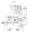
同期電動機の磁極位置の検出、あるいは電動機電流の検出を行うことなく、同期電動機を制御する方法で、位置センサを用いない方法に、図33に示すものがある。この従来技術では、位置センサの代わりに、電動機電流を検出する電流センサを用いる。この従来技術は、同期電動機の位置センサ付きベクトル制御に基づいて、位置センサの代わりに、磁極位置推定器と速度推定器を設ける(以後、ベクトル制御型センサレス方式と呼ぶ)。この構成は、磁極位置の検出部と速度の検出部以外は、位置センサを付けたベクトル制御方式と全く同じである。
【0003】
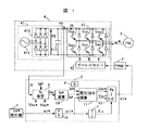
図33において、符号1は回転速度指令ωr* の速度指令発生器、2Yは電動機の制御装置、3は電圧指令をPWM(パルス幅変調)パルスに変換するPWM発生器、4はインバータ、5は同期電動機、6は機械角周波数を電気角周波数に変換する変換ゲイン、8はd軸電流指令Id* を発生するId* 発生器、11はdq軸上の電圧指令Vdc*,Vqc*を演算する電圧指令演算器、12はdq軸上の値を三相交流の値に変換するdq逆変換器、13は信号の加算減算を行う加算器、27は速度推定値が速度指令に一致するようにIq* を調整する速度制御器、30は電流推定値Idc,Iqcが、各々の指令値Id*,Iq*に一致するように、電圧指令Vdc*,Vqc*に補正を加える電流制御器、37は電動機の磁極軸を推定する磁極位置推定器、38は電動機の回転速度を推定する速度推定器、39は三相交流を回転座標上の値に変換するdq座標変換器、41はインバータの直流電源、42はインバータの主回路部、43はPWMパルスに基づいてインバータ主回路の半導体スイッチング素子Sup〜Swnをオン・オフするゲートドライバ、44は電動機の電流を検出する電流センサである。
【0004】
図33の磁極位置推定器37が、磁極位置センサに相当し、速度推定器38が速度センサに相当する。また、速度制御器27と電流制御器30を、位置センサ付きベクトル制御装置と同様に備えており、速度,電流が各々の指令値に一致するように自動調整する。これは、例えば、平成12年電気学会産業応用部門全国大会,講演論文集[III],No.97,p.963−966,「軸誤差の直接推定演算による永久磁石同期モータの位置センサレス制御」に記載されている。
【0005】
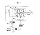
位置センサと電動機電流センサのいずれも用いない図34に示す制御方法の従来技術が、特開平6−153526号公報や、特開平8−19263号公報に開示されている。図34で符号40はインバータの直流電流I0とPWMパルス波形から、電動機電流を推定演算するモータ電流推定器であり、他の符号は、図33と同一である。
【0006】
図34では、電動機電流を直接検出せずに、インバータの直流電流を電流センサ44で検出する。モータ電流推定器40では、直流電流の検出値I0と、PWM発生器3の出力パルス波形に基づいて電動機電流を推定し、この推定値I1cを制御装置2Yへ出力する。制御装置2Yでは、I1cに基づいて、例えば図33と同様に、ベクトル型センサレス制御する。
【0007】
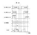
次に、モータ電流推定器40の動作を、図35(a)〜(c)を用いて説明する。図35(a)〜(c)は、各相のPWMパルス波形を示しており、それぞれ「1」の時にプラス側のスイッチ(Sup,Svp,Swp)をオン、「0」の時にはマイナス側のスイッチ(Sun,Svn,Swn)をオンする。今、電動機電流が図35(d)のような場合を仮定すると、インバータの直流電流検出値I0は、図35(e)のような波形になる。図35(e)の波形には、次の4つのモードがある。

【0008】
【発明が解決しようとする課題】
図33に示したベクトル制御型センサレス方式の場合、電動機に電流センサ44が必須であり、センサ44を用いることによる信頼性の低下の問題や、高精度な制御を実現するためには高価な電流センサを用いる必要があるなど、コスト面での問題がある。また、図32の方法では、スイッチングに伴って発生する電流の高周波振動(リンギング)の問題がある。リンギングは、電動機の配線ケーブルが長いほど発生しやすので、本来検出すべき電流値を検出することが困難になる。また、電動機の回転周波数が低い条件では、PWMパルスの幅が狭くなり、例え配線ケーブルを短くしても、ノイズの影響を受けやすくなり、検出精度が劣化する。
【0009】
本発明は、電動機電流センサを用いずに信頼性を確保し、なお且つ、リンギング等のノイズの影響を受け難い高性能な同期電動機の駆動システムを提供することを目的とする。
【0010】
【課題を解決するための手段】
本発明の同期電動機の駆動システムは、同期電動機を駆動するインバータの直流電流を検出し、その大きさから、電動機に流れるトルク電流成分を推定し、その推定値に基づいて電動機への印加電圧を決定し、トルク電流の推定値を用いて、電動機内部の磁極軸推定演算を行う。
【0011】
本発明の同期電動機の駆動システムは、同期電動機と、該同期電動機に交流を印加するインバータと、該インバータへ電力を供給する直流電源と、該直流電源から前記インバータに供給する電流を検出する手段と、前記同期電動機に回転数指令を与える手段と、前記同期電動機内部の磁極軸を仮定したdc軸と、該dc軸に直交する軸であるqc軸のそれぞれの軸上の電流指令Id*と電流指令Iq*とを与える手段と、前記電流指令Id*と電流指令Iq*と前記回転数指令とに基づいて、dc−qc軸上の電圧指令を演算する手段とを備えていて、該電圧指令に基づいて、前記インバータに制御信号を送り、前記直流電源の電流検出値に基づいて、前記同期電動機内部のトルク電流成分を推定演算し、該推定演算値に基づいて、前記電流指令Iq* を生成する。
【0012】
【発明の実施の形態】
以下本発明の実施例を図面を用いて詳しく説明する。
【0013】
(実施例1)
図1に本実施例の構成図を示す。図1において、符号1は電動機に回転速度指令ωr* を与える速度指令発生器、2は電動機の印加電圧を演算する制御装置、3は電圧指令V1* に基づいて、インバータ4を駆動するパルスを生成するPWM(パルス幅変調)発生器、4は電動機を駆動する半導体スイッチング素子からなるインバータ、5は制御対象の同期電動機、6は回転速度指令ωr* を、電動機の電気角周波数指令ω1* に変換する変換ゲイン(Pは電動機の極数)、7は電気角周波数指令ω1* に基づいて、制御装置内部の交流位相θcを演算する積分器、8は電動機の磁極軸成分(d軸成分)の電流指令Id* を与えるId* 発生器、9はインバータの直流電流検出値I0に基づいて、電動機のトルク電流成分を推定演算するIq推定器、10は電動機のトルク電流成分(q軸成分)推定値Iqcに基づいて、電流指令Iq* を演算するIq* 演算器、11は電気角周波数指令ω1* ,電流指令Id* ,電流指令Iq* に基づいて、dc−qc軸上の電圧指令Vdc*,Vqc*を演算する電圧指令演算器、12はdc−qc軸上の電圧指令Vdc*,Vqc*を、三相交流軸上の値に変換するdq逆変換器、41はインバータ4の主回路電源を構成する直流電源部、42はインバータの主回路部、43は主回路へのゲート信号を発生するゲート・ドライバ、44はインバータの直流電流を検出する電流センサ、411はインバータ4に電力を供給する三相交流電源、412は三相交流電源を整流するダイオード・ブリッジ、413は直流電源に含まれる脈動成分を抑制する平滑コンデンサである。
【0014】
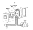
図2に示す本実施例の電動機駆動システムは、交流電源,制御・インバータ部,電動機に分けられる。図2に示すように、制御・インバータ部にある制御ボード上に、上記符号1から3に示す機能を備えていて、これらはマイクロ・プロセッサーをベースにしたディジタル回路である。また、インバータ主回路部,電流検出部なども、一つの装置内に実装されている。
【0015】
次に、図1に基づいて、本実施例の動作を説明する。速度指令ωr* に基づき、電動機の電気角周波数指令ω1* が、変換ゲイン6の出力として得られる。積分器7では、電気角周波数指令ω1* を積分して、制御器内部での交流位相θcを得る。
【0016】
また、Iq推定器9では、直流電流検出値I0に基づいて、電動機のトルク電流成分を推定演算し、Iq* 演算器では、その電動機のトルク電流成分推定値Iqcに基づいて電流指令Iq* を演算する。Id* 発生器8では、所定の電流指令Id* を発生し、例えば、電動機の回転子構造が非突極型の場合は電流指令Id*=0を与える。電圧指令演算器11では、電動機の電気角周波数指令ω1*と電流指令Id*,Iq*に基づいて、同期電動機5への印加電圧である電圧指令Vdc*と電圧指令Vqc*を下式で演算する。
【0017】
【数1】
式(1)の演算式は、通常のベクトル制御で用いているものであって、例えば、「ACサーボシステムの理論と設計の実際」杉本英彦著,総合電子出版、p.78の式(4.6)に記載がある。
【0019】
次に、式(1)で求めた電圧指令Vdc*とVqc*を、交流位相θcを用いて三相交流軸上の電圧指令値V1* に座標変換する。PWM発生器3では、電圧指令値V1* をPWMパルス信号に変換する。ゲート・ドライバ43は、このパルス信号に基づいてスイッチング素子を駆動し、同期電動機5に電圧指令Vdc*,Vqc*に相当する電圧を印加する。
【0020】
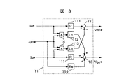
次に、各部の動作を説明する。電圧指令演算器11では、式(1)に基づいて、電圧指令を演算する。式(1)をブロック図で表すと、図3のようになる。図3において、符号13は加算器(減算も含む)、14は乗算器、111は電動機の抵抗値(R)に相当するゲイン、112はd軸インダクタンス(Ld)に相当するゲイン、113はq軸インダクタンス(Lq)に相当するゲイン、114は発電定数(Ke)に相当するゲインである。
【0021】
式(1)と図3とに示すように、電圧指令は電動機の定数のR,Ld,Lq,Keを用いて演算する。これらの電動機定数が正確であれば、電動機は指令値通りの回転速度,電流値で駆動する。電圧指令演算器11に与える電気角周波数指令ω1* と電流指令Id* は、電動機の負荷状態に無関係に与えることができるが、電流指令Iq* は、電動機が必要なトルクに応じて与える必要があり、電流指令Iq* と、実際のトルク負荷とに差異が生じると、電動機の磁極軸と制御軸とが一致せず、不安定やトルク不足の原因になるので、電流指令Iq* を如何に作成するかが制御のポイントになる。図33に示した従来技術のベクトル制御型センサレス方式では、速度制御器27の出力を電流指令Iq* としている。しかし、ベクトル制御型センサレス方式の場合、速度推定器や、速度制御器といった構成要素が必要となり、制御構成が複雑になるため、本実施例では、直流電流検出値I0からトルク電流成分を推定演算し、その推定値Iqcに基づいて、電流指令Iq* を作成する。
【0022】
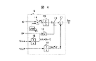
図4に、Iq推定器9の構成を示す。図4において、符号13と14は、図3と同一である。図4で、符号15は、直流電圧の設定値V0を発生するV0*発生器、16は電力の換算ゲイン、17は除算器、18は信号を1サンプル周期だけ遅延する遅延器である。
【0023】
次に、図4の動作を説明する。電動機が消費する電力に関して、直流電源部と、dq座標軸上との関係を式で表現すると、
【0024】
【数2】
のようになる。ここで、係数3/2は、dq座標の変換に相対変換を用いた場合の係数である。絶対変換を用いれば、係数は1となる。式(2)を変形すると、
【0026】
【数3】
となり、直流電流検出値I0から電動機のトルク電流成分Iqが演算できる。ただし、インバータの直流電圧V0と電動機電圧Vd,Vq、電動機に流れる電流Idは、直接検出できないので、それぞれ設定値、あるいは指令値を用いて、
【0028】
【数4】
として、電動機のトルク電流成分Iqを推定演算する。式(4)をブロック図で表現したものが図4である。Vdc*とVqc*は、演算周期分だけ遅れた値を用いる。
【0030】
次に、トルク電流成分推定値Iqcを用いて電流指令Iq* を作成する。図1における符号10が、Iq*演算器であり、ここでは次式に従って、電流指令Iq*を演算する。
【0031】
【数5】
式(5)は、一次遅れフィルタであるが、これ以外にも移動平均値などを用いてもよい。トルク電流成分推定値Iqcを直接電流指令Iq* とすると、ポジティブに動作し、制御系が不安定になるので、遅れ要素を与えて安定化している。ただし、定常的にはトルク電流成分推定値Iqcの基本波成分(すなわち、直流成分)と電流指令Iq* が一致するため、結果的に電動機内部の磁極軸と制御軸が一致し、安定した電動機駆動システムが実現できる。このように本実施例によれば、制御構成を極端に単純化した構成で、電動機を安定に駆動できる電動機駆動システムが実現できる。
【0033】
(実施例2)
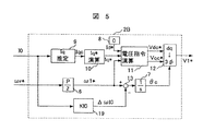
図5を用いて本実施例を説明する。図5は、制御装置2Bの構成を示し、本制御装置2Bを、図1の制御装置2の代わりに用いる。図5の符号6〜13は、実施例1の同一番号のものと同じである。符号19は、インバータの直流電流検出値I0を用いて、電気角周波数指令ω1* に修正値ΔωI0を加えるI0ダンピング・ゲインである。本実施例は実施例1に、I0ダンピング・ゲイン19を追加した。
【0034】
次に、本実施例の動作を説明する。電動機の消費電力は、式(2)に示す関係にあるため、電動機負荷が変化し、消費電力が増加すると、直流電圧V0が一定であれば直流電流検出値I0が増加する。よって、直流電流検出値I0が増加した場合は、負荷外乱が発生し、それに伴って電動機の速度低下が生じる。電動機を脱調させずに、負荷変動に対応するには、制御装置内部の速度を、負荷に応じて低減すればよい。よって、直流電流検出値I0を用いて、電気角周波数指令ω1* を修正すれば、負荷外乱に応じて、電動機の回転速度を変化させて、脱調を防止できる。
【0035】
なお、電気角周波数ω1* の修正量ΔωI0は、定常状態では零にする必要があるので、I0ダンピング・ゲイン19は、微分要素、あるいは不完全微分要素で構成すればよい。本実施例によれば、負荷変動に対しても安定に駆動できる。
【0036】
(実施例3)
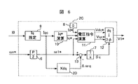
図6を用いて本実施例を説明する。図6は、制御装置2Cの構成を示し、本制御装置2Cを、実施例1の制御装置2の代わりに用いる。図6において、符号6〜13は、実施例1と同一番号のものと同じであり、符号20はトルク電流の推定値Iqcを用いて、電気角周波数指令ω1* に修正値Δωqを加えるIqダンピング・ゲインである。本実施例は、実施例1にIqダンピング・ゲイン20を追加した。
【0037】
次に、本実施例の動作を説明する。実施例2では、直流電流検出値I0を用いて、電気角周波数指令ω1* に修正を加えたが、本実施例では、トルク電流推定値Iqcを用いて電気角周波数指令ω1* を修正する。直流電流検出値I0は、電動機の消費電力に起因して変化する物理量であるが、直接負荷トルクに関係した値ではないので、電動機速度が低い領域では、負荷トルク変動が大きくても直流電流検出値I0の変化は僅である。従って、負荷トルクの変動に対しては、負荷トルクと相関関係の強いトルク電流成分を用いた方が、より忠実な電気角周波数指令ω1* の補償が実現できる。本実施例では、トルク電流成分推定値Iqcを用いて電気角周波数指令ω1* を修正し、低速域でのトルク外乱に対する安定性を改善した。
【0038】
なお、電気角周波数指令ω1* の修正値Δωqは、定常状態では零にする必要があるので、Iqダンピング・ゲイン20は、I0ダンピング・ゲイン19と同様に、微分要素、あるいは不完全微分要素で構成する。本実施例により、低速域でのトルク負荷変動に対しても安定に駆動できる。
【0039】
(実施例4)
図7〜図9を用いて本実施例を説明する。図7は、制御装置2Dの構成を示し、本制御装置2Dを、図1の制御装置2の代わりに用いる。図7において、符号6〜13は、前述の実施例における同一番号のものと同じである。符号21は電動機の磁極軸と、制御軸との軸誤差を推定演算する軸誤差推定器、22は軸誤差に零指令を与える零発生器、23は軸誤差に基づいて電気角周波数指令ω1* への修正量を演算する磁極軸推定ゲインである。
【0040】
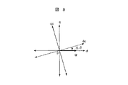
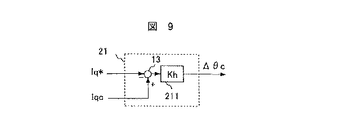
次に、図7を用いて本実施例の動作を説明する。図1の制御装置2に対して、符号21〜23を加えたものが、本実施例である。軸誤差推定器21では、電動機内部の磁極軸と制御内の磁極軸の誤差Δθを推定演算する。誤差Δθは、図8に示すように、電動機内部のdq軸から観測した制御軸(dc−qc軸と定義する)の誤差成分と定義する。誤差推定値Δθcの演算は下記式に従って行う。
【0041】
【数6】
Δθc=Kh(Iqc−Iq*) …(数6)
式(6)を具現化したブロックが、図9であって、符号211は、誤差演算のための比例ゲインKhである。Iq* は、電動機に印加している電圧値の基になっているトルク電流指令値であり、それと現時点でのトルク電流成分(推定値)Iqcとが一致していれば、軸誤差は零とみなすことができる。仮に、両者に差が生じた場合は、それに比例した誤差Δθが、dq軸とdc−qc軸との間に発生していることになる。よって、式(6)に示すように、Iq* とIqcとの差を演算し、比例ゲインKhを介して、誤差推定値Δθcを求めることができる。
【0042】
誤差推定値Δθcが正の場合、図8に示す関係より、制御軸dc−qc軸が、dq軸よりも進んでいるので、電気角周波数指令ω1* を減少するように補正量Δω1(この場合は、Δω1<0)を加え、誤差Δθを減らす。逆に、誤差推定値Δθcが負の場合は、電気角周波数指令ω1* を増加するように補正量Δω1を加える。これらの動作(PLL動作)を実現しているのが、図7におけるブロック21〜23である。磁極軸推定ゲイン23は、誤差推定値Δθcの収束時間を決定する係数であり、基本的には比例ゲインでよいが、比例・積分、あるいは微分要素等を組み合わせてもよい。本実施例によって、軸ずれを補償し、より高性能な電動機制御を実現できる。
【0043】
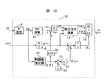
(実施例5)
図10を用いて本実施例を説明する。図10は、制御装置2Eの構成を示し、本制御装置2Eを、図1の制御装置2の代わりに用いる。図10において、符号6〜13と21〜23は、前述の実施例の同一番号のものと同じである。符号24は磁極軸の誤差推定値Δθcに基づいて、電流指令Iq* を演算するトルク制御器である。本実施例と、実施例4との違いは、トルク制御器24を追加した点である。
【0044】
次に、図10の動作を説明する。本実施例では、磁極軸の誤差推定値Δθcを用いて電流指令Iq* を決定する。電動機に印加されている交流電圧の位相θcは、主に電気角周波数指令ω1* の積分により与えられているため、負荷が急変した場合、まず初めに変化するのは誤差推定値Δθcである。もちろん、磁極軸推定ゲイン23を介して、電気角周波数指令ω1* は修正されるが、実速度に一致するまでには、PLLの設定応答に応じた時間がかかる。よって、誤差推定値Δθcの変化から即座に電流指令Iq* を決定することで、高応答なトルク制御が実現できる。
【0045】
なお、図10におけるIq* 演算器10を用いない場合は、誤差推定値Δθcは、定常的に零になるので、トルク制御器内部に積分要素が必要になる。その場合、トルク制御器24は、PI(比例・積分)制御、あるいはPID(比例・積分・微分)制御等を基本に構成すればよい。逆に、Iq* 演算器と併用する場合は、トルク制御器は比例要素、あるいは微分要素で構成すればよい。本実施例によればトルク変化に応じた電流指令を迅速に得ることができる。
【0046】
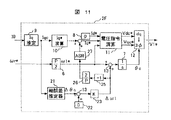
(実施例6)
図11を用いて本実施例を説明する。図11は、制御装置2Fの構成を示し、本制御装置2Fを、図1の制御装置2の代わりに用いる。図11において、符号6〜13と21〜23とは、前述の実施例の同一番号のものと同じである。符号25は信号の符号を反転する反転ゲイン、26は電気角周波数を機械角周波数に変換する変換ゲイン、27は電動機の速度を一定に制御する速度制御器である。本実施例と、実施例5との構成の違いは、トルク制御器24の代わりに符号25〜27が追加された点である。
【0047】
次に、図11の動作を説明する。本実施例は、磁極軸推定ゲイン23が出力する補正量Δω1を用いて、電流指令Iq* を作成する。本実施例では、速度偏差を迅速に零に収束させるため、速度制御器27を設けて電流指令Iq* を作成する。速度偏差に、電気角周波数指令ω1* の補正量Δω1を用いて、制御構成を単純化する。
【0048】
磁極軸推定ゲイン23が出力する補正量Δω1は、電動機の実速度が、制御装置内の速度指令よりも高い場合に正の値となるので、反転ゲイン25を介して符号を反転する。これによって、従来技術の速度制御器、例えば、図31の速度制御器27における入力(速度偏差)と等価になる。次に、変換ゲイン26により、電動機の極対数Pで補正量Δω1を除算し、機械角周波数の偏差に変換する。最後に、速度制御器27を用いて、電流指令Iq* を演算する。速度制御器27は、例えば、従来技術の速度制御に用いるPI制御,PID制御などを用いればよい。また、Iq* 演算器と併用する場合は、前述の実施例5と同様に、速度制御器を比例、あるいは微分要素で構成すればよい。
【0049】
本実施例によれば電気角周波数指令ω1* の補正量Δω1に基づいて速度制御器を構成することで、速度追従性のよい電動機駆動システムが実現できる。
【0050】
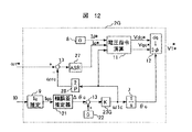
(実施例7)
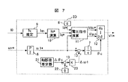
図12を用いて本実施例を説明する。図12は、制御装置2Gの構成を示し、本制御装置2Gを、図1の制御装置2の代わりに用いる。図12において、符号6〜9,11〜13,21,22,26と27は、前述の実施例の同一番号のものと同じである。符号23Gは、積分を含む要素で構成された磁極軸推定ゲインである。本実施例と、実施例6との構成の違いは、電気角周波数指令ω1* から直接交流位相θcを演算するループがない代わりに磁極軸推定ゲイン23Gの出力に基づいて、交流位相θcを演算している点と、磁極軸推定ゲインの出力と、回転速度指令ωr* の偏差に基づいて、速度制御器27が電流指令Iq* を演算している点である。
【0051】
次に、図12の動作を説明する。本実施例では、磁極軸推定ゲイン23Gに積分要素を持たせ、その値に基づいて交流位相θcを演算する。この結果、制御装置内の交流位相θcが、実際の電動機速度に合わせて変化するので電動機の脱調が防止できる。
【0052】
制御装置2Gでは、直流電流検出値I0を用いて、Iq推定器9でトルク電流成分推定値Iqcを演算し、その演算結果に基づいて、誤差推定値Δθcを演算する。誤差推定値Δθcを零にするように、磁極軸推定ゲイン23Gが、電気角周波数ω1cを出力する。この磁極軸推定ゲイン23Gは、速度推定器としても機能し、これを用いて速度制御を行う。磁極軸推定ゲイン23Gの出力である電気角周波数ω1cに、変換ゲイン26を介することで速度推定値ωrcを得る。この速度推定値ωrcと回転速度指令ωr* との偏差を速度制御器27に入力し、電流指令Iq* を得る。図12では、速度制御器27が積分要素を持つ。
【0053】
ここで、前記の実施例(例えば、図7に示す実施例4)に対して、本実施例の磁極軸推定ゲイン23Gを用いても問題はない。以上、本実施例によれば、電動機と負荷装置の慣性に依存せずに、速度指令に追従できる電動機駆動システムが実現できる。
【0054】
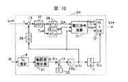
なお、図10,図11,図12の実施例では、トルク制御器24、あるいは速度制御器27の出力を用いて、電流指令Iq* を得ているが、これらの制御器出力に基づいて、電流指令Id* を得ることもできる。図13は、図12の制御装置に対して、速度制御器出力を用いて、電流指令Id* と電流指令Iq* とを演算している例である。図13において、符号7,9,11〜13,21,22,23G,26,27は、これまでの実施例における同じ番号のものと同一である。符号28と29は、速度制御器の出力に基づいて、電流指令Id* と電流指令Iq* とを出力するId* データテーブルとIq* データテーブルである。
【0055】
突極型の同期電動機の場合、永久磁石によるトルクだけでなく、電動機の突極性を活かしたリラクタンストルクを利用して、効率を改善できる。その場合、電流指令Id* を常に零に制御するのではなく、必要なトルクに応じて、電動機に流れるトータルの電流値を最小にする電流指令Id* と電流指令Iq* を与える。図13の場合、速度制御器の出力をトルク指令Tm* とみなし、そのトルクに必要な電流指令Id*,Iq*をそれぞれのデータテーブルより得る。トルク指令Tm* から電流指令Id*,Iq*を得る方法は、例えば、特開平2000−116198号公報の図2,図3等に記載がある。
【0056】
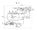
(実施例8)
図14を用いて本実施例を説明する。図14は、制御装置2Jを示したものであり、本制御装置2Jを、図1における制御装置2の代わりに用いる。図14で符号6〜9,11〜13,21〜23,25〜27は、前述の実施例の同一番号のものと同じである。符号30は、q軸成分推定値Iqcの値を電流指令Iq* に一致させるための電流制御器である。
【0057】
次に、本実施例の動作を説明する。図10〜図13に示した前記実施例によれば、Iq* 演算器10を用いずに電流指令Iq* を得ることができる。また、q軸成分推定値Iqc自体は、直流電流検出値I0から演算できるので、Iqcを電流指令Iq* に一致するように、自動制御できる。図14は、図11の制御構成に、電流制御器30を付加した。電流制御器30を用いて、q軸成分推定値Iqcと電流指令Iq* とが一致するように、電圧指令Vqc* に補正を加えている。この構成より、電流指令Iq* に、速やかにq軸成分推定値Iqcを一致させることができ、制御性能がさらに改善する。なお、q軸成分電流Iqの電流制御器は、他の実施例、例えば、図10,図12,図13の実施例にも適用できる。
【0058】
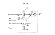
(実施例9)
図15を用いて本実施例を説明する。図15は軸誤差推定器21Kの構成を示したものであり、推定器21Kを、これまでの各実施例における軸誤差推定器21の代わりに用いる。図15の符号13,14,17,18,111,113は、これまでの実施例の同一番号のものと同じである。
【0059】
次に、本実施例の動作を説明する。これまでの各実施例における軸誤差演算器では、式(6)(図9)に従って、誤差推定値Δθcを演算した。本実施例では以下のように誤差推定値Δθcを演算する。電動機の電圧方程式は、
【0060】
【数7】
である。上式より、
【0062】
【数8】
である。また、電圧指令Vdc*,Vqc*と、実際の同期電動機のdq軸上の電圧Vd,Vqの関係は、誤差Δθを用いると、
【0064】
【数9】
となる。式(8)と式(9)より、
【0066】
【数10】
が得られる。ここで、cosΔθ≒1,sinΔθ≒Δθの近似を行うと、
【0068】
【数11】
が得られる。上式において、微分項を無視すると、
【0070】
【数12】
が得られる。式(12)を、Id=Id*,Iq=Iqcと置き換え、ブロック図で表現すると、図15の構成が得られ、電動機速度の広い範囲にわたって、精度の高い誤差Δθの推定演算が可能であるので、推定誤差Δθcが図9よりさらに改善される。この結果、より高精度・高性能な電動機駆動システムが実現できる。
【0072】
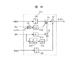
(実施例10)
図16を用いて本実施例を説明する。図16は、軸誤差推定器21Lの構成を示し、軸誤差推定器21Lをこれまでの実施例における軸誤差推定器21の代わりに用いる。図16の符号13,14,17,18,111,113は、これまでの実施例の同一番号のものと同じである。図16の符号212は、進み要素(微分、あるいは不完全微分要素)の制御ブロックである。
【0073】
次に、本実施例の動作を説明する。本実施例では実施例9で、前記式(11)の微分項を、無視せずに図16に示す構成にしたことだけが異なる。図16の構成により、電動機の電圧方程式から得られる原理式に、微分項を含めて忠実に再現しているため、過渡時においても精度よく軸誤差演算が実現できる。この結果、より高精度・高性能な電動機駆動システムが実現できる。
【0074】
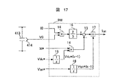
(実施例11)
図17を用いて本実施例を説明する。図17は、Iq推定器9Mの構成を示し、本Iq推定器9Mを、これまでの実施例におけるIq推定器9の代わりに用いる。図17において、符号13,14,16〜18と413は、前述の実施例の同一番号のものと同じである。符号414は、平滑コンデンサ413の電圧を検出する電圧センサである。
【0075】
本実施例と、図4との相違点は、インバータの直流電圧を検出する電圧センサ414を設け、その検出値V0を用いて、トルク電流の推定演算を行っている点である。本実施例によれば、直流電圧の検出値を用いてIqcを演算できるため、直流電圧の変動に対してロバストな制御ができる。
【0076】
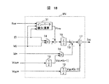
(実施例12)
図18を用いて本実施例を説明する。図18は、Iq推定器9Nの構成を示し、本推定器9Nを、これまでの実施例におけるIq推定器9の代わりに用いる。図18において、符号13,14,16〜18は、前述の実施例の同一番号のものと同じである。符号31はインバータで消費される損失分を演算するインバータ損失演算器である。本実施例と、図9と図17との相違点は、インバータ損失演算器31が付加された点である。
【0077】
本実施例では、インバータが消費する損失分を考慮して、q軸成分推定値Iqcを演算する。インバータの損失Pinv を含めた電力の関係式を式(13)に示す。
【0078】
【数13】
上式において、fswはインバータの平均スイッチング周波数、Kvはスイッチングに伴い発生するスイッチング損失に相当する係数、Kiはインバータに流れる電流の大きさに依存して発生する損失係数である。式(13)に基づいて、q軸成分推定値Iqcを演算すると、次式のようになる。
【0080】
【数14】
式(14)を実際のブロック図で表すと、図18に示す構成になる。式(13),(14)におけるPinv を計算する際の各係数、Kv,Kiは、実験的に求めて、予め設定する。
【0082】
以上のように、図18に示すIq推定器9Nを用いることで、インバータで発生する損失分を考慮して、q軸成分推定値Iqcをさらに精度よく推定できる。
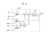
(実施例13)
図19を用いて本実施例を説明する。図19は、インバータ損失演算器31Pの構成を示し、本演算器31Pを、図18におけるインバータ損失演算器31の代わりに用いる。図19の符号13,14は、前述の実施例の同一番号のものと同じである。符号311は電力の換算ゲイン、312は積分器(時定数Te)を用いた損失推定器である。本実施例では、インバータ損失をオンラインで推定し、q軸成分推定値Iqcを演算する。
【0083】
式(13)における左辺(直流入力電力)と、右辺第1項(電動機の消費電力)との差が、インバータが消費する電力であるので、これら入出力のパワーの差を演算し、インバータの損失Pinv として、q軸成分推定値Iqcに補正を加える。図19では、直流側の消費電力演算と、電動機側の消費電力演算をそれぞれ行い、それらの差を積分し、インバータ損失Pinv を推定する。
【0084】
以上のように、図19の構成のインバータ損失演算器31Pを用いて、インバータで発生する損失分をオンラインで演算し、q軸成分推定値Iqcを精度よく計算できる。
【0085】
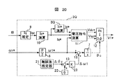
(実施例14)
図20を用いて本実施例を説明する。図20は、制御装置2Qの構成を示し、本制御装置2Qを、図1における制御装置2の代わりに用いる。図20において、符号6,7,9〜13,21〜23は、前述の実施例の同一番号のものと同じである。符号8Qは、電流指令Iq* に基づいて、電流指令Id* の値を決定するId* 発生器である。
【0086】
次に、本実施例の動作を説明する。永久磁石型電動機には、永久磁石によるトルクと、電動機の突極性(逆突極性)によるリラクタンストルクとを組み合わせて、電動機トルクを発生するものがある。この種の電動機の場合、電動機電流Idをマイナスに流した範囲に電動機の最大トルク点あり、Id=0に制御することは、効率の面で得策ではない。すなわち、常に最小電流、すなわち最大効率で電動機を駆動する場合は、常に最大トルクで電動機を駆動するとよい。最大トルクを得る条件は、例えば「PMモータの制御法と回転子構造による特性比較」、電気学会論文誌D,平成6年,114巻6号,pp.662−667に記載があって、この文献中の式(5)に従うと、
【0087】
【数15】
となり、トルク電流成分Iqが定まれば、最大トルクを得る電動機電流Idが決定する。
【0089】
本実施例では、Id* 発生器8Qが、電流指令Iq* を用いて式(15)で電動機電流Idを演算し、最大トルクすなわち最大効率で電動機を駆動できる。なお、式(15)の演算に、電流指令Iq* でなくq軸成分推定値Iqcを用いることもできるが、過渡時におけるq軸成分推定値Iqcの変動が激しいので、制御系全体が不安定になる恐れがある。また、効率の最大化を定常状態で実願すれば現実には十分であるので、Iq* 演算器の出力の電流指令Iq* を用いても何ら問題はない。以上、本実施例によって、電動機効率を最大にして運転できる。
【0090】
(実施例15)
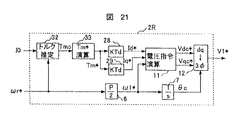
図21,図22を用いて本実施例を説明する。図21は、制御装置2Rの構成を示し、本制御装置2Rを、図1の制御装置2の代わりに用いる。図21で、符号6,7,11,12,28,29は、前述の実施例における同一番号のものと同じである。符号32は直流電流検出値I0に基づいて、電動機の発生するトルクを推定演算するトルク推定器、符号33はトルク推定値Tmcに基づいて、トルク指令Tm* を演算するTm* 演算器である。
【0091】
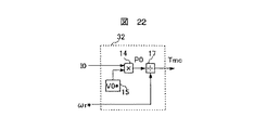
本実施例は電動機の発生トルクを直接推定演算する。電動機の発生トルクと、出力Pmの関係は、
【0092】
【数16】
Pm=ωrTm …(数16)
ただし、Tm:電動機の発生トルク、ωr:電動機の回転速度
となる。よって、直流側の消費電力が、式(16)に等しいことから、
【0093】
【数17】
のように、直接電動機トルクを推定演算できる。式(17)をブロック図で表すと、図22に示すようになる。
【0095】
図21では、トルク推定器32で、直流電流検出値I0から直接電動機トルクを推定演算し、その後、Tm* 演算器で、トルク指令Tm* を演算する。トルク指令Tm* の演算には、実施例1と同様に、遅れ要素(例えば、式(5))を用いている。トルク指令Tm*が得られれば、それに必要な電流指令Id*,Iq*を、データテーブル28と29とを用いて作成する。データテーブル28,29は、実施例7(図13)で説明したものをそのまま用いれば良い。
【0096】
本実施例によれば、トルク推定器を用いて、電動機の発生トルクを推定することが可能であり、その結果、簡単な制御構成で、電動機の効率最大化制御が実現でき、簡便で汎用性の高い制御ができる。
【0097】
(実施例16)
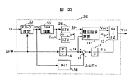
図23を用いて本実施例を説明する。図23は、制御装置2Sの構成を示し、本制御装置2Sを、図1における制御装置2の代わりに用いる。図23において、符号6,7,11,12,28,29,32,33は、前述の実施例における同一番号のものと同じである。符号34は、トルク推定値Tmcを用いて、電気角周波数指令ω1* に修正値Δωqを加えるトルク・ダンピング・ゲインである。本実施例は、図21の実施例に対して、トルク・ダンピング・ゲイン34を追加した。
【0098】
トルク推定器32では、実際の電動機トルクを瞬時に観測できるため、電動機の負荷変動はトルク推定値Tmcの変化となって現れるので、トルク推定値Tmcを用いて、電気角周波数指令ω1* を修正すれば、負荷外乱に応じて、電動機の回転速度を変化させて脱調を防止できる。なお、電気角周波数指令ω1* の修正量ΔωTmは、定常状態では零にする必要があるので、トルク・ダンピング・ゲイン34は、微分要素、あるいは不完全微分要素で構成すればよい。
【0099】
以上、本実施例によって、負荷変動に対しても安定に駆動できる。
【0100】
(実施例17)
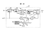
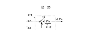
図24と図25を用いて本実施例を説明する。図24は、制御装置2Tの構成を示し、本制御装置2Tを、図1の制御装置2の代わりに用いる。図24で、符号6,7,11〜13,22,23,28,29,32,33は、前述の実施例における同一番号のものと同じである。符号21Tは電動機の磁極軸と、制御軸との軸誤差を推定演算する軸誤差推定器である。
【0101】
次に、図24の動作を説明する。図21の制御装置2Rに対して、符号21T,22,23を加えたものが、本実施例である。軸誤差推定器21Tでは、トルク指令Tm* と、トルク推定値Tmcに基づいて、誤差推定値Δθcを下記式で演算する。
【0102】
【数18】
Δθc=Kth(Tmc−Tm*) …(数18)
式(18)を具現化したブロックが、図25である。図25において、符号211Tは、軸誤差演算のための比例ゲインKthである。トルク指令Tm* とその時点でのトルク推定値Tmcとが一致していれば、誤差Δθは零とみなせる。仮に、両者に差が生じた場合は、それに比例した誤差Δθが、dq軸とdc−qc軸との間に発生していることになる。よって、式(18)に示すように、トルク指令Tm* とトルク推定値Tmcの差を演算し、比例ゲインKthを介することで、誤差Δθを推定できる。誤差推定値Δθcが求まれば、これまでの実施例と同様に、磁極軸推定ゲイン23を介して、交流位相θcを修正することで、誤差推定値Δθcを零に制御できる。
【0103】
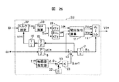
(実施例18)
図26を用いて本実施例を説明する。図26は、制御装置2Uの構成を示し、本制御装置2Uを、図1における制御装置2の代わりに用いる。図26において、符号6,7,11〜13,18,21T,22,23,26,28,29,32,33は、前述の実施例における同一番号のものと同じである。本実施例では、トルク推定演算に用いている回転速度を、回転速度指令ωr* ではなく、回転速度推定値ωrcを用いている点が、図24の実施例と異なる。
【0104】
回転速度推定値ωrcは、図26に示すように、電気角周波数指令ω1* に補正量Δω1を加算した後の値の電気角周波数を、換算ゲイン26を介して機械角周波数に換算しいる。電動機のトルクと、電力との関係は、式(16)に示すように、実際の回転速度を用いる方が、原理的に正確な値が得られるので、回転速度指令より、速度推定値を用いて計算する方が、高い精度のトルク推定が行える。以上、本実施例によれば、より高い精度でトルクを推定できる。
【0105】
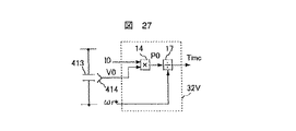
(実施例19)
図27を用いて本実施例を説明する。図27は、トルク推定器32Vの構成を示し、本トルク推定器32Vを、これまでの実施例におけるトルク推定器32の代わりに用いる。図27において、符号14,17,413,414は、前述の実施例の同一番号のものと同じである。本実施例のトルク推定器では、インバータの直流電圧を検出する電圧センサ414を設け、直流電圧検出値V0を用いて、トルク推定値Tmcの演算を行う。本実施例によれば、直流電圧の検出値を用いてトルク推定値Tmcを演算できるため、電源電圧の変動や、電動機負荷が変動に伴う直流電圧の変動に対してロバストな制御ができる。
【0106】
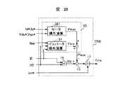
(実施例20)
図28を用いて本実施例を説明する。図28は、トルク推定器32Wの構成を示し、本トルク推定器32Wを、これまでの実施例におけるトルク推定器32、あるいはトルク推定器32Vの代わりに用いる。図28において、符号13,14,17,31は、前述の実施例の同一番号のものと同じである。符号35は電動機のトルク出力以外の全ての損失分Plossを演算する全損失演算器、351は電動機の銅損,鉄損を演算するモータ損失演算器である。
【0107】
本実施例と、図22、あるいは図27との相違点は、インバータ損失演算器31とモータ損失演算器351からなる全損失演算器35が付加された点である。本実施例では、図18の実施例と同様に、損失分すべてを演算する全損失演算器35を設けて、トルク推定値Tmcを演算する。全損失演算器におけるインバータ損失演算器31は、前述の実施例と同じものなので説明を省略する。また、モータ損失演算器351においては、電動機の損失分Pmot を、下記式に従って演算する。
【0108】
【数19】
Ploss=Kr(Id*2+Iq*2)+Km(Vdc*2+Vqc*2) …(数19)
上式において、Krは電動機の銅損に起因する損失分、Krmは鉄損の銅損に起因する損失分である。全損失分Plossは、
【0109】
【数20】
Ploss=Pinv+Pmot …(数20)
となる。上式における損失を考慮し、トルク推定を行うと、図28の構成になる。以上のように、図28の構成のトルク推定器を用いることで、インバータと電動機で発生する損失分を考慮することが可能になり、トルク推定値Tmcをさらに精度よく計算できる。
【0110】
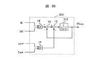
(実施例21)
図29を用いて本実施例を説明する。図29は、全損失演算器35Xの構成を示し、本演算器35Xを、図28における全損失演算器35の代わりに用いる。図29において、符号13,14,312は、前述の実施例の同一番号のものと同じであるトルク出力以外の全損失をオンラインで推定し、トルク推定演算の精度を改善する。直流の入力電力P0と、全損失Ploss,トルクTmの関係は、
【0111】
【数21】
P0=ωr・Tm+Ploss …(数21)
であるので、トルク出力Pm(=ωr・Tm)と入力電力P0の差を演算し、Plossを推定演算すれば、オンラインで損失成分が得られる。この動作を具現化したものが、図29である。図29では、直流側の消費電力演算と、電動機のトルク出力演算をそれぞれ行い、それらの差を積分し、全損失Plossを推定している。
【0112】
以上のように、本実施例のインバータ損失演算器を用いることで、トルク出力以外の損失分をオンラインで演算することが可能になり、トルク推定値Tmcをさらに精度よく推定できる。
【0113】
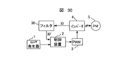
(実施例22)
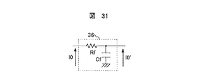
図30,図31を用いて本実施例を説明する。図30は、本実施例の同期電動機の駆動システムの構成を示す。本実施例は、これまでの実施例における直流電流の検出値I0に対して、フィルタ36を付加する。フィルタ36で、直流電流の検出値I0に含まれる高調波成分を削除する。フィルタ36は例えば、図31に示すコンデンサCfと抵抗Rfとからなる一次遅れフィルタである。
【0114】
実際の直流電流検出値I0は、例えば、図32(b)に示すような脈動成分を伴う波形である。これまでの実施例を実現する上で必要な値は、直流電流の平均的な値(図32(b)におけるI0m)であるので、直流電流検出値I0をそのまま演算に用いることは難しい。そこで、例えば、三角波キャリアの周期よりも十分短い時間で、直流電流をサンプリングし、その平均値を求めることも考えられるが、それには高速な演算処理が必要になるので実用的ではない。そこで、図31に示すフィルタを挿入し、インバータのスイッチングに伴う脈動成分を削除し、直流電流の平均的な値を検出するようにする。なお、フィルタの時定数Tf(=Cf・Rf)は、インバータの平均スイッチング周期(三角波キャリアの周期)より長く設定すれば、主要な脈動成分を除去できる。なお、本実施例のフィルタは、これまで説明した全ての実施例に対して実施できる。
【0115】
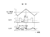
(実施例23)
図32を用いて本実施例を説明する。本実施例は、フィルタ時定数を極力小さくし、なお且つ、脈動成分の影響を受けない直流電流の検出方法である。図32は、実施例22の動作波形を示す。図32(a)は、PWMパルス波形を作成する際に使用する三角波キャリア、図32(b)は、直流電流検出値I0、図32(c)はフィルタ36を通過した後の直流電流検出値I0の波形(I0′)である。フィルタ時定数を必要最小限に設定しているため、I0′には、高調波のリプル成分が残っている。
【0116】
図32(b)に示す直流電流の検出値I0は、三角波キャリアに同期した波形となり、三角波キャリアのピーク(正側,負側,両方のピーク)で必ず零になる。直流電流の検出値I0が零の状態は、すなわち、インバータのスイッチング素子が、上側すべてがオン(図1のSup,Svp,Swpがすべてオン)、あるいは下側すべてがオン(図1のSun,Svn,Swnがすべてオン)の状態であり、この条件では直流電源とインバータとが切り離されている。
【0117】
この直流電流検出値I0が零になる期間(図32のt0の期間)では、フィルタ後の電流I0′が、緩やかに変化し、必ず平均値I0mと交差する。よって、t0期間のタイミングを見計らって、I0′をサンプリングし、その値を制御に用いれば、制御に必要な直流電流検出値I0の平均的な値を読み取ることができるので、フィルタ後の電流I0′に多少のリプルが含まれていても問題はない。よって、本実施例によれば、直流電流の検出フィルタ時定数を最小限に設定し、制御応答を劣化させることなく、高性能な電動機駆動システムができる。
【0118】
【発明の効果】
本発明による電動機駆動システムによれば、電動機を制御するための位置・速度センサと電動機電流センサを用いることなく、単純な制御構成で、高性能・高精度な電動機駆動が実現できる。この結果、電動機駆動システムの信頼性・安定性が向上する。
【図面の簡単な説明】
【図1】実施例1の構成図である。
【図2】実施例1の電動機駆動システムを実装した装置の構造概略図である。
【図3】実施例1の電圧指令演算器の構成図である。
【図4】実施例1のIq推定器の構成図である。
【図5】実施例2の構成図である。
【図6】実施例3の構成図である。
【図7】実施例4の構成図である。
【図8】電動機内のdq軸と制御装置内のdc−qc軸と、誤差Δθの関係を示すベクトル図である。
【図9】実施例4の軸誤差推定器の構成図である。
【図10】実施例5の構成図である。
【図11】実施例6の構成図である。
【図12】実施例7の構成図である。
【図13】実施例7の別の構成図である。
【図14】実施例8の構成図である。
【図15】実施例9の構成図である。
【図16】実施例10の構成図である。
【図17】実施例11の構成図である。
【図18】実施例12の構成図である。
【図19】実施例13の構成図である。
【図20】実施例14の構成図である。
【図21】実施例15の構成図である。
【図22】実施例15のトルク推定器の構成図である。
【図23】実施例16の構成図である。
【図24】実施例17の構成図である。
【図25】実施例17の軸誤差推定器の構成図である。
【図26】実施例18の構成図である。
【図27】実施例19の構成図である。
【図28】実施例20の構成図である。
【図29】実施例21の構成図である。
【図30】実施例22の構成図である。
【図31】実施例23のフィルタの構成図である。
【図32】実施例23の動作波形を示す図である。
【図33】従来技術の位置・速度センサレスによる同期電動機ベクトル制御システムの構成図である。
【図34】従来技術の電動機電流センサを用いない同期電動機駆動システムの構成図である。
【図35】従来技術の電動機電流センサを用いない同期電動機駆動システムの動作を示す図である。
【符号の説明】
1…速度指令発生器、2,2B,2C,2D,2E,2F,2G,2Q,2R,2S,2T,2U,2Y…制御装置、3…PWM(パルス幅変調)発生器、4…インバータ、5…同期電動機、6…変換ゲイン(Pは電動機の極数)、7…積分器、8,8Q…Id* 発生器、9,9M,9N…Iq推定器、10…Iq* 演算器、11…電圧指令演算器、12…dq逆変換器、13…加算器、14…乗算器、15…V0* 発生器、16…電力の換算ゲイン、17…除算器、18…遅延器、19…I0ダンピング・ゲイン、20…Iqダンピング・ゲイン、21,21K,21L,21T…軸誤差推定器、22…零発生器、23,23G…磁極軸推定ゲイン、24…トルク制御器、25…反転ゲイン、26…変換ゲイン、27…速度制御器、28…Id* データテーブル、29…Iq* データテーブル、30…電流制御器、31,31P…インバータ損失演算器、32,32V,32W…トルク推定器、33…Tm* 演算器、34…トルク・ダンピング・ゲイン、35,35X…全損失演算器、36…フィルタ、37…磁極位置推定器、38…速度推定器、39…dq座標変換器、40…モータ電流推定器、41…直流電源部、42…インバータ主回路部、43…ゲート・ドライバ、44…電流センサ、111…電動機の抵抗値(R)に相当するゲイン、112…d軸インダクタンス(Ld)に相当するゲイン、113…q軸インダクタンス(Lq)に相当するゲイン、114…発電定数(Ke)に相当するゲイン、211…比例ゲインKh、211…進み要素の制御ブロック、211T…比例ゲインKth、311…電力の換算ゲイン、312…損失推定器、351…モータ損失演算器、411…三相交流電源、412…ダイオード・ブリッジ、413…平滑コンデンサ、414…電圧センサ。[0001]
BACKGROUND OF THE INVENTION
The present invention relates to a control system for a synchronous motor, and more particularly to a high-accuracy and high-performance synchronous motor drive system having a simplified control configuration without using a sensor for detecting the speed and position of the motor and a motor current sensor.
[0002]
[Prior art]
FIG. 33 shows a method for controlling the synchronous motor without detecting the magnetic pole position of the synchronous motor or the motor current, and without using a position sensor. In this prior art, a current sensor for detecting the motor current is used instead of the position sensor. In this prior art, based on vector control with a position sensor of a synchronous motor, a magnetic pole position estimator and a speed estimator are provided instead of the position sensor (hereinafter referred to as a vector control type sensorless system). This configuration is exactly the same as the vector control method with a position sensor except for the magnetic pole position detection unit and the speed detection unit.
[0003]
33,
[0004]
33 corresponds to the magnetic pole position sensor, and the
[0005]
The prior art of the control method shown in FIG. 34 using neither a position sensor nor an electric motor current sensor is disclosed in Japanese Patent Laid-Open Nos. 6-153526 and 8-19263. In FIG. 34,
[0006]
In FIG. 34, the direct current of the inverter is detected by the
[0007]
Next, the operation of the motor
[0008]
[Problems to be solved by the invention]
In the case of the vector control type sensorless system shown in FIG. 33, the
[0009]
SUMMARY OF THE INVENTION An object of the present invention is to provide a high-performance synchronous motor drive system that ensures reliability without using a motor current sensor and is hardly affected by noise such as ringing.
[0010]
[Means for Solving the Problems]
The drive system for a synchronous motor according to the present invention detects a direct current of an inverter that drives the synchronous motor, estimates a torque current component flowing through the motor from the magnitude thereof, and calculates an applied voltage to the motor based on the estimated value. Then, using the estimated value of the torque current, the magnetic pole axis estimation calculation inside the motor is performed.
[0011]
A drive system for a synchronous motor according to the present invention includes a synchronous motor, an inverter that applies AC to the synchronous motor, a DC power source that supplies power to the inverter, and a means that detects a current supplied to the inverter from the DC power source. A means for giving a rotational speed command to the synchronous motor, a dc axis assuming a magnetic pole axis inside the synchronous motor, and a current command Id * on each axis of the qc axis which is an axis orthogonal to the dc axis, Means for giving a current command Iq *, and means for calculating a voltage command on the dc-qc axis based on the current command Id *, the current command Iq * and the rotation speed command, A control signal is sent to the inverter based on the command, a torque current component inside the synchronous motor is estimated based on the current detection value of the DC power supply, and the current command I is calculated based on the estimated calculation value. Generate q *.
[0012]
DETAILED DESCRIPTION OF THE INVENTION
Embodiments of the present invention will be described in detail below with reference to the drawings.
[0013]
Example 1
FIG. 1 shows a configuration diagram of this embodiment. In FIG. 1,
[0014]
The motor drive system of this embodiment shown in FIG. 2 is divided into an AC power source, a control / inverter unit, and an electric motor. As shown in FIG. 2, on the control board in the control / inverter section, the functions shown in the above-mentioned
[0015]
Next, the operation of this embodiment will be described with reference to FIG. Based on the speed command ωr *, an electric angular frequency command ω1 * of the motor is obtained as an output of the
[0016]
The
[0017]
[Expression 1]
The equation (1) is used in normal vector control. For example, “AC servo system theory and design practice”, Hidehiko Sugimoto, General Electronic Publishing, p. 78 (4 .6).
[0019]
Next, the voltage commands Vdc * and Vqc * obtained by the equation (1) are coordinate-converted to a voltage command value V1 * on the three-phase AC axis using the AC phase θc. The
[0020]
Next, the operation of each unit will be described. The
[0021]
As shown in Equation (1) and FIG. 3, the voltage command is calculated using the constants R, Ld, Lq, and Ke of the motor. If these motor constants are accurate, the motor is driven at the rotational speed and current value as instructed. The electrical angular frequency command ω1 * and the current command Id * given to the
[0022]
FIG. 4 shows the configuration of the
[0023]
Next, the operation of FIG. 4 will be described. Regarding the power consumed by the motor, the relationship between the DC power supply unit and the dq coordinate axis is expressed by an equation:
[0024]
[Expression 2]
become that way. Here, the
[0026]
[Equation 3]
Thus, the torque current component Iq of the motor can be calculated from the DC current detection value I0. However, since the inverter DC voltage V0, the motor voltages Vd and Vq, and the current Id flowing through the motor cannot be directly detected, the set value or command value is used respectively.
[0028]
[Expression 4]
The torque current component Iq of the electric motor is estimated and calculated. FIG. 4 is a block diagram of Expression (4). As Vdc * and Vqc *, values delayed by the calculation period are used.
[0030]
Next, a current command Iq * is created using the torque current component estimated value Iqc.
[0031]
[Equation 5]
Equation (5) is a first-order lag filter, but a moving average value or the like may be used in addition to this. When the torque current component estimated value Iqc is directly set as the current command Iq *, the operation is positive and the control system becomes unstable, so that a delay element is added to stabilize. However, since the fundamental wave component (that is, the direct current component) of the torque current component estimated value Iqc and the current command Iq * coincide with each other in a steady state, the magnetic pole axis inside the motor coincides with the control axis, resulting in a stable motor. A drive system can be realized. As described above, according to the present embodiment, it is possible to realize an electric motor drive system capable of stably driving an electric motor with a configuration in which the control configuration is extremely simplified.
[0033]
(Example 2)
The present embodiment will be described with reference to FIG. FIG. 5 shows the configuration of the control device 2B, and this control device 2B is used in place of the
[0034]
Next, the operation of this embodiment will be described. Since the electric power consumption of the electric motor is in the relationship shown in Expression (2), when the electric motor load changes and the electric power consumption increases, the DC current detection value I0 increases if the DC voltage V0 is constant. Therefore, when the DC current detection value I0 increases, a load disturbance occurs, and the motor speed decreases accordingly. In order to cope with load fluctuations without causing the motor to step out, the speed inside the control device may be reduced according to the load. Therefore, if the electrical angular frequency command ω1 * is corrected using the detected DC current value I0, the step-out can be prevented by changing the rotational speed of the electric motor according to the load disturbance.
[0035]
Since the correction amount ΔωI0 of the electrical angular frequency ω1 * needs to be zero in the steady state, the
[0036]
(Example 3)
The present embodiment will be described with reference to FIG. FIG. 6 shows the configuration of the control device 2C, and this control device 2C is used in place of the
[0037]
Next, the operation of this embodiment will be described. In the second embodiment, the electric angular frequency command ω1 * is corrected using the DC current detection value I0. However, in the present embodiment, the electric angular frequency command ω1 * is corrected using the torque current estimated value Iqc. The DC current detection value I0 is a physical quantity that changes due to the power consumption of the motor, but is not directly related to the load torque. Therefore, in the region where the motor speed is low, the DC current detection is possible even if the load torque fluctuation is large. The change in value I0 is negligible. Therefore, more accurate compensation of the electrical angular frequency command ω1 * can be realized when the torque current component having a strong correlation with the load torque is used. In this embodiment, the electrical angular frequency command ω1 * is corrected using the estimated torque current component value Iqc to improve the stability against torque disturbance in the low speed range.
[0038]
Since the correction value Δωq of the electrical angular frequency command ω1 * needs to be zero in the steady state, the
[0039]
Example 4
The present embodiment will be described with reference to FIGS. FIG. 7 shows the configuration of the control device 2D, and this control device 2D is used in place of the
[0040]
Next, the operation of this embodiment will be described with reference to FIG. In this embodiment,
[0041]
[Formula 6]
Δθc = Kh (Iqc−Iq *) (Equation 6)
FIG. 9 shows a block that embodies Equation (6), and
[0042]
When the error estimated value Δθc is positive, the control axis dc−qc axis is ahead of the dq axis from the relationship shown in FIG. 8, and therefore the correction amount Δω1 (in this case) so as to reduce the electrical angular frequency command ω1 *. Adds Δω1 <0) and reduces the error Δθ. Conversely, when the error estimated value Δθc is negative, the correction amount Δω1 is added so as to increase the electrical angular frequency command ω1 *. These operations (PLL operation) are realized by the
[0043]
(Example 5)
The present embodiment will be described with reference to FIG. FIG. 10 shows the configuration of the
[0044]
Next, the operation of FIG. 10 will be described. In this embodiment, the current command Iq * is determined using the error estimation value Δθc of the magnetic pole axis. Since the phase θc of the AC voltage applied to the motor is mainly given by the integration of the electrical angular frequency command ω1 *, when the load changes suddenly, the error estimated value Δθc changes first. Of course, the electrical angular frequency command ω1 * is corrected via the magnetic pole
[0045]
If the Iq *
[0046]
(Example 6)
The present embodiment will be described with reference to FIG. FIG. 11 shows the configuration of the
[0047]
Next, the operation of FIG. 11 will be described. In this embodiment, the current command Iq * is created using the correction amount Δω1 output from the magnetic pole
[0048]
The correction amount Δω1 output by the magnetic pole
[0049]
According to the present embodiment, by configuring the speed controller based on the correction amount Δω1 of the electrical angular frequency command ω1 *, it is possible to realize an electric motor drive system with good speed followability.
[0050]
(Example 7)
This embodiment will be described with reference to FIG. FIG. 12 shows the configuration of the
[0051]
Next, the operation of FIG. 12 will be described. In the present embodiment, the magnetic pole
[0052]
In
[0053]
Here, there is no problem even if the magnetic pole
[0054]
10, 11, and 12, the current command Iq * is obtained using the output of the
[0055]
In the case of a salient pole type synchronous motor, the efficiency can be improved by utilizing not only the torque by the permanent magnet but also the reluctance torque utilizing the saliency of the motor. In this case, the current command Id * is not always controlled to zero, but a current command Id * and a current command Iq * that minimize the total current value flowing through the motor are given according to the required torque. In the case of FIG. 13, the output of the speed controller is regarded as a torque command Tm *, and current commands Id * and Iq * necessary for the torque are obtained from the respective data tables. A method for obtaining the current commands Id * and Iq * from the torque command Tm * is described in, for example, FIGS. 2 and 3 of Japanese Patent Laid-Open No. 2000-116198.
[0056]
(Example 8)
The present embodiment will be described with reference to FIG. FIG. 14 shows a
[0057]
Next, the operation of this embodiment will be described. 10 to 13, the current command Iq * can be obtained without using the Iq *
[0058]
Example 9
The present embodiment will be described with reference to FIG. FIG. 15 shows the configuration of the
[0059]
Next, the operation of this embodiment will be described. In the axial error calculators in the embodiments so far, the error estimated value Δθc is calculated according to the equation (6) (FIG. 9). In this embodiment, the error estimated value Δθc is calculated as follows. The voltage equation of the motor is
[0060]
[Expression 7]
It is. From the above formula,
[0062]
[Equation 8]
It is. Further, the relationship between the voltage commands Vdc * and Vqc * and the voltages Vd and Vq on the dq axis of the actual synchronous motor is obtained by using an error Δθ.
[0064]
[Equation 9]
It becomes. From Equation (8) and Equation (9),
[0066]
[Expression 10]
Is obtained. Here, when approximating cosΔθ≈1, sinΔθ≈Δθ,
[0068]
[Expression 11]
Is obtained. In the above equation, ignoring the differential term,
[0070]
[Expression 12]
Is obtained. When Expression (12) is replaced with Id = Id *, Iq = Iqc and expressed in a block diagram, the configuration of FIG. 15 is obtained, and the error Δθ can be accurately calculated over a wide range of the motor speed. Therefore, the estimation error Δθc is further improved from that in FIG. As a result, a motor drive system with higher accuracy and higher performance can be realized.
[0072]
(Example 10)
This embodiment will be described with reference to FIG. FIG. 16 shows the configuration of the axis error estimator 21L, and the axis error estimator 21L is used in place of the
[0073]
Next, the operation of this embodiment will be described. The present embodiment is different from the ninth embodiment only in that the differential term of the equation (11) is not ignored and is configured as shown in FIG. With the configuration of FIG. 16, the principle equation obtained from the voltage equation of the motor is faithfully reproduced including the differential term, so that the axis error calculation can be realized with high accuracy even in a transient state. As a result, a motor drive system with higher accuracy and higher performance can be realized.
[0074]
(Example 11)
The present embodiment will be described with reference to FIG. FIG. 17 shows the configuration of the
[0075]
The difference between the present embodiment and FIG. 4 is that a
[0076]
(Example 12)
The present embodiment will be described with reference to FIG. FIG. 18 shows the configuration of the Iq estimator 9N, and this estimator 9N is used in place of the
[0077]
In the present embodiment, the q-axis component estimated value Iqc is calculated in consideration of the loss consumed by the inverter. Expression (13) shows a relational expression of power including the inverter loss Pinv.
[0078]
[Formula 13]
In the above equation, fsw is an average switching frequency of the inverter, Kv is a coefficient corresponding to the switching loss generated by switching, and Ki is a loss coefficient generated depending on the magnitude of the current flowing through the inverter. When the q-axis component estimated value Iqc is calculated based on Expression (13), the following expression is obtained.
[0080]
[Expression 14]
When Expression (14) is represented by an actual block diagram, the configuration shown in FIG. 18 is obtained. The coefficients Kv and Ki for calculating Pinv in equations (13) and (14) are experimentally determined and set in advance.
[0082]
As described above, by using the Iq estimator 9N shown in FIG. 18, the q-axis component estimated value Iqc can be estimated with higher accuracy in consideration of the loss generated in the inverter.
(Example 13)
The present embodiment will be described with reference to FIG. FIG. 19 shows the configuration of the
[0083]
Since the difference between the left side (DC input power) in equation (13) and the first term on the right side (power consumption of the motor) is the power consumed by the inverter, the difference between the input and output power is calculated, As the loss Pinv, the q-axis component estimated value Iqc is corrected. In FIG. 19, the DC power consumption calculation and the motor power consumption calculation are performed, and the difference between them is integrated to estimate the inverter loss Pinv.
[0084]
As described above, by using the
[0085]
(Example 14)
The present embodiment will be described with reference to FIG. FIG. 20 shows a configuration of the
[0086]
Next, the operation of this embodiment will be described. Some permanent magnet type motors generate electric motor torque by combining the torque of a permanent magnet and the reluctance torque due to the saliency (reverse saliency) of the motor. In the case of this type of motor, there is a maximum torque point of the motor in a range in which the motor current Id flows negatively, and it is not a good idea in terms of efficiency to control to Id = 0. That is, when the electric motor is always driven with the minimum current, that is, the maximum efficiency, the electric motor is always driven with the maximum torque. Conditions for obtaining the maximum torque are described in, for example, “Comparison of PM motor control method and rotor structure characteristics”, IEEJ Transactions D, 1994, Vol. 114, No. 6, pp. 662-667. According to equation (5) in the literature:
[0087]
[Expression 15]
When the torque current component Iq is determined, the motor current Id for obtaining the maximum torque is determined.
[0089]
In this embodiment, the Id * generator 8Q can calculate the motor current Id by the equation (15) using the current command Iq * and drive the motor with the maximum torque, that is, the maximum efficiency. Although the q-axis component estimated value Iqc can be used in the calculation of the equation (15) instead of the current command Iq *, the fluctuation of the q-axis component estimated value Iqc at the time of transition is so severe that the entire control system is unstable. There is a risk of becoming. Moreover, since it is sufficient in practice to apply for the maximum efficiency in a steady state, there is no problem even if the current command Iq * output from the Iq * calculator is used. As described above, according to this embodiment, the motor efficiency can be maximized.
[0090]
(Example 15)
A present Example is described using FIG. 21, FIG. FIG. 21 shows the configuration of the
[0091]
In this embodiment, the generated torque of the electric motor is directly estimated and calculated. The relationship between the generated torque of the motor and the output Pm is
[0092]
[Expression 16]
Pm = ωrTm (Expression 16)
Where Tm: generated torque of the motor, ωr: rotational speed of the motor
It becomes. Therefore, since the power consumption on the DC side is equal to Equation (16),
[0093]
[Expression 17]
Thus, the motor torque can be estimated and calculated directly. Expression (17) is represented in a block diagram as shown in FIG.
[0095]
In FIG. 21, the
[0096]
According to the present embodiment, it is possible to estimate the generated torque of the motor using a torque estimator, and as a result, it is possible to realize the motor efficiency maximization control with a simple control configuration, which is simple and versatile. High control is possible.
[0097]
(Example 16)
The present embodiment will be described with reference to FIG. FIG. 23 shows a configuration of the control device 2S, and this control device 2S is used in place of the
[0098]
In the
[0099]
As described above, according to the present embodiment, it is possible to drive stably even with respect to load fluctuation.
[0100]
(Example 17)
A present Example is described using FIG. 24 and FIG. FIG. 24 shows the configuration of the
[0101]
Next, the operation of FIG. 24 will be described. This embodiment is obtained by adding
[0102]
[Formula 18]
Δθc = Kth (Tmc−Tm *) (Equation 18)
FIG. 25 shows a block that embodies Equation (18). In FIG. 25,
[0103]
(Example 18)
This embodiment will be described with reference to FIG. FIG. 26 shows a configuration of the
[0104]
As shown in FIG. 26, the estimated rotational speed value ωrc is obtained by converting the electrical angular frequency obtained by adding the correction amount Δω1 to the electrical angular frequency command ω1 * into the mechanical angular frequency via the
[0105]
Example 19
This embodiment will be described with reference to FIG. FIG. 27 shows the configuration of the
[0106]
(Example 20)
This embodiment will be described with reference to FIG. FIG. 28 shows a configuration of the
[0107]
The difference between this embodiment and FIG. 22 or FIG. 27 is that a
[0108]
[Equation 19]
Ploss = Kr (Id * 2 + Iq * 2 ) + Km (Vdc * 2 + Vqc * 2 ) (Equation 19)
In the above equation, Kr is the loss due to the copper loss of the motor, and Krm is the loss due to the copper loss of the iron loss. The total loss Ploss is
[0109]
[Expression 20]
Ploss = Pinv + Pmot (Equation 20)
It becomes. When the torque is estimated in consideration of the loss in the above equation, the configuration shown in FIG. 28 is obtained. As described above, by using the torque estimator having the configuration shown in FIG. 28, it is possible to consider the loss generated in the inverter and the electric motor, and the torque estimated value Tmc can be calculated with higher accuracy.
[0110]
(Example 21)
This embodiment will be described with reference to FIG. FIG. 29 shows the configuration of the
[0111]
[Expression 21]
P0 = ωr · Tm + Ploss (Expression 21)
Therefore, the loss component can be obtained online by calculating the difference between the torque output Pm (= ωr · Tm) and the input power P0 and estimating Ploss. FIG. 29 shows the implementation of this operation. In FIG. 29, the power consumption calculation on the DC side and the torque output calculation of the motor are performed, and the difference between them is integrated to estimate the total loss Ploss.
[0112]
As described above, by using the inverter loss calculator of this embodiment, it is possible to calculate a loss other than the torque output online, and the estimated torque value Tmc can be estimated more accurately.
[0113]
(Example 22)
A present Example is described using FIG. 30, FIG. FIG. 30 shows the configuration of the synchronous motor drive system of the present embodiment. In the present embodiment, a
[0114]
The actual DC current detection value I0 is, for example, a waveform with a pulsating component as shown in FIG. Since the value necessary for realizing the embodiments so far is the average value of the direct current (I0m in FIG. 32B), it is difficult to directly use the detected direct current value I0 for the calculation. Thus, for example, it is conceivable to sample the direct current in a time sufficiently shorter than the period of the triangular wave carrier and obtain the average value thereof, but this is not practical because it requires high-speed arithmetic processing. Therefore, the filter shown in FIG. 31 is inserted to eliminate the pulsation component accompanying the switching of the inverter and detect the average value of the direct current. Note that if the time constant Tf (= Cf · Rf) of the filter is set longer than the average switching period of the inverter (period of the triangular wave carrier), the main pulsation component can be removed. In addition, the filter of a present Example can be implemented with respect to all the Examples demonstrated so far.
[0115]
(Example 23)
This embodiment will be described with reference to FIG. The present embodiment is a DC current detection method that minimizes the filter time constant and is not affected by the pulsating component. FIG. 32 shows operation waveforms of the twenty-second embodiment. FIG. 32A is a triangular wave carrier used when creating a PWM pulse waveform, FIG. 32B is a DC current detection value I 0, and FIG. 32C is a DC current detection value after passing through the
[0116]
The detected value I0 of the direct current shown in FIG. 32B is a waveform synchronized with the triangular wave carrier, and is always zero at the peak of the triangular wave carrier (positive side, negative side, both peaks). When the detected value I0 of the DC current is zero, that is, all the switching elements of the inverter are on (Sup, Svp, Swp in FIG. 1 are all on), or all the lower sides are on (Sun, FIG. 1). Svn and Swn are all on). Under this condition, the DC power supply and the inverter are disconnected.
[0117]
During the period when the DC current detection value I0 is zero (period t0 in FIG. 32), the filtered current I0 ′ changes gently and always crosses the average value I0m. Therefore, if the I0 ′ is sampled at the timing of the t0 period and the value is used for the control, the average value of the DC current detection value I0 necessary for the control can be read, so the filtered current I0 There is no problem even if some ripples are included in ′. Therefore, according to the present embodiment, a high-performance motor drive system can be achieved without setting the DC current detection filter time constant to a minimum and degrading the control response.
[0118]
【The invention's effect】
According to the motor drive system of the present invention, high-performance and high-precision motor drive can be realized with a simple control configuration without using a position / speed sensor and a motor current sensor for controlling the motor. As a result, the reliability and stability of the motor drive system are improved.
[Brief description of the drawings]
FIG. 1 is a configuration diagram of
FIG. 2 is a schematic structural diagram of an apparatus in which the motor drive system according to the first embodiment is mounted.
FIG. 3 is a configuration diagram of a voltage command calculator according to the first embodiment.
4 is a configuration diagram of an Iq estimator according to
5 is a configuration diagram of Example 2. FIG.
6 is a configuration diagram of
7 is a configuration diagram of
FIG. 8 is a vector diagram showing a relationship between a dq axis in the electric motor, a dc-qc axis in the control device, and an error Δθ.
FIG. 9 is a configuration diagram of an axis error estimator according to the fourth embodiment.
10 is a configuration diagram of
11 is a configuration diagram of
12 is a configuration diagram of
FIG. 13 is another configuration diagram of the seventh embodiment.
14 is a configuration diagram of
15 is a configuration diagram of
16 is a configuration diagram of Example 10. FIG.
17 is a configuration diagram of Example 11. FIG.
18 is a configuration diagram of Example 12. FIG.
19 is a configuration diagram of Example 13. FIG.
20 is a configuration diagram of Example 14. FIG.
FIG. 21 is a configuration diagram of Example 15.
22 is a configuration diagram of a torque estimator according to
23 is a configuration diagram of Example 16. FIG.
24 is a configuration diagram of Example 17. FIG.
25 is a configuration diagram of an axis error estimator according to
26 is a configuration diagram of Example 18. FIG.
27 is a configuration diagram of Example 19. FIG.
28 is a configuration diagram of Example 20. FIG.
29 is a block diagram of Example 21. FIG.
30 is a configuration diagram of Example 22. FIG.
31 is a configuration diagram of a filter of Example 23. FIG.
32 is a diagram showing operation waveforms in Example 23. FIG.
FIG. 33 is a block diagram of a conventional synchronous motor vector control system without position / speed sensors.
FIG. 34 is a block diagram of a synchronous motor drive system that does not use a conventional motor current sensor.
FIG. 35 is a diagram showing the operation of a synchronous motor drive system that does not use a motor current sensor of the prior art.
[Explanation of symbols]
DESCRIPTION OF
Claims (14)
前記直流電源の電流検出値に基づいて前記同期電動機内部のトルク電流成分を推定演算し、該推定演算値に基づいて、前記qc軸成分の電流指令Iq* を生成することを特徴とした同期電動機駆動システム。A synchronous motor, an inverter for applying alternating current to the synchronous motor, a DC power supply for supplying power to the inverter, means for detecting a current supplied from the DC power supply to the inverter, and a rotational speed command to the synchronous motor Means for giving, a dc axis assuming a magnetic pole axis inside the synchronous motor, and means for giving a current command Id * and a current command Iq * on the respective axes of the qc axis which is an axis orthogonal to the dc axis; Means for calculating a voltage command on the dc-qc axis based on the current command Id *, the current command Iq * and the rotation speed command, and sending a control signal to the inverter based on the voltage command. In the synchronous motor drive system for controlling the synchronous motor,
A synchronous motor that estimates and calculates a torque current component inside the synchronous motor based on a current detection value of the DC power supply, and generates a current command Iq * of the qc-axis component based on the estimated calculation value Driving system.
前記直流電源の電流検出値に基づいて前記同期電動機内部のトルク電流成分を推定演算し、該推定演算値に遅れ要素を与えた値に基づいて前記qc軸成分の電流指令IqA torque current component inside the synchronous motor is estimated based on the detected current value of the DC power source, and the qc axis component current command Iq is calculated based on a value obtained by adding a delay element to the estimated calculated value. * * を生成することを特徴とした同期電動機駆動システム。Synchronous motor drive system characterized by generating
前記直流電源の電流検出値に基づき、前記同期電動機内部のトルク電流成分を推定演算し、該推定演算値に基づいて、前記回転数指令を補償することを特徴とした同期電動機駆動システム。A synchronous motor drive system characterized in that a torque current component inside the synchronous motor is estimated based on a detected current value of the DC power source, and the rotational speed command is compensated based on the estimated calculated value.
前記直流電源の電流検出値に基づいて、前記同期電動機内部の磁極軸に直交する成分であるトルク電流成分を推定演算する手段と、前記トルク電流成分の推定値を用いて、前記d軸と、前記dc軸との誤差Δθを演算する手段と、該誤差Δθに基づいて前記電流指令Iq* を生成する手段とを備えることを特徴とした同期電動機駆動システム。A synchronous motor, an inverter for applying alternating current to the synchronous motor, a DC power supply for supplying power to the inverter, means for detecting a current supplied from the DC power supply to the inverter, and a rotational speed command to the synchronous motor Means for giving, a dc axis assuming a magnetic pole axis (d axis) inside the synchronous motor, and means for giving a current command Id * and a current command Iq * on the qc axis which is an axis orthogonal to the dc axis; Means for calculating a voltage command on the dc-qc axis based on the current command Id *, current command Iq * and the rotational speed command, and sending a control signal to the inverter based on the voltage command. In the synchronous motor drive system for controlling the synchronous motor,
Based on the detected current value of the DC power supply, means for estimating a torque current component that is a component orthogonal to the magnetic pole axis in the synchronous motor, and using the estimated value of the torque current component, the d axis, A synchronous motor drive system comprising: means for calculating an error Δθ with respect to the dc axis; and means for generating the current command Iq * based on the error Δθ.
前記直流電源の電流検出値に基づいて、前記同期電動機内部の磁極軸に直交する成分であるトルク電流成分を推定演算する手段と、前記トルク電流成分の推定値を用いて、前記d軸と、前記dc軸との誤差Δθを演算し、該誤差Δθに基づいて、前記交流位相に修正を加える手段と、前記交流位相を修正する修正量に基づいて電流指令Iq* を生成する手段を備えることを特徴とした同期電動機駆動システム。A synchronous motor, an inverter for applying alternating current to the synchronous motor, a DC power supply for supplying power to the inverter, means for detecting a current supplied from the DC power supply to the inverter, and a rotational speed command to the synchronous motor A means for calculating an AC phase of the synchronous motor based on the rotational speed command, a dc axis assuming a magnetic pole axis (d axis) inside the synchronous motor, and an axis orthogonal to the dc axis A means for giving a current command Id * and a current command Iq * on the qc axis, and a means for calculating a voltage command on the dc-qc axis based on the current command and the rotation speed command. In the synchronous motor drive system that controls the synchronous motor by sending a control signal to the inverter based on the voltage command,
Based on the detected current value of the DC power supply, means for estimating a torque current component that is a component orthogonal to the magnetic pole axis in the synchronous motor, and using the estimated value of the torque current component, the d axis, Means for calculating an error Δθ with respect to the dc axis, correcting the AC phase based on the error Δθ, and generating a current command Iq * based on the correction amount for correcting the AC phase; Synchronous motor drive system characterized by
前記直流電源の電流検出値に基づいて、前記同期電動機内部の磁極軸に直交する成分であるトルク電流成分Iqを推定演算する手段と、前記トルク電流成分の推定値Iqcを用いて、前記d軸と、前記dc軸との誤差Δθを演算し、該誤差Δθ基づいて、前記同期電動機の回転数を推定する手段と、該回転数の推定値に基づいて、前記同期電動機の交流位相を演算する手段と、前記回転数指令と前記回転数推定値との偏差に基づいて、電流指令
Iq* を生成する手段を備えることを特徴とした同期電動機駆動システム。A synchronous motor, an inverter for applying alternating current to the synchronous motor, a DC power supply for supplying power to the inverter, means for detecting a current supplied from the DC power supply to the inverter, and a rotational speed command to the synchronous motor Means for giving, a dc axis assuming a magnetic pole axis (d axis) inside the synchronous motor, and means for giving a current command Id * and a current command Iq * on the qc axis which is an axis orthogonal to the dc axis; Means for calculating a voltage command on the dc-qc axis based on the current command and the rotation speed command, and based on the voltage command, sends a control signal to the inverter to control the synchronous motor In the synchronous motor drive system,
Based on the current detection value of the DC power supply, the d-axis is calculated using means for estimating a torque current component Iq that is a component orthogonal to the magnetic pole axis in the synchronous motor, and the estimated value Iqc of the torque current component. And an error Δθ with respect to the dc axis, a means for estimating the rotational speed of the synchronous motor based on the error Δθ, and an AC phase of the synchronous motor based on the estimated value of the rotational speed And a means for generating a current command Iq * based on a deviation between the rotation speed command and the rotation speed estimated value.
Priority Applications (2)
| Application Number | Priority Date | Filing Date | Title |
|---|---|---|---|
| JP2001170425A JP3867518B2 (en) | 2001-06-06 | 2001-06-06 | Sensorless control system for synchronous motor |
| US10/053,694 US6690137B2 (en) | 2001-06-06 | 2002-01-24 | Sensorless control system for synchronous motor |
Applications Claiming Priority (1)
| Application Number | Priority Date | Filing Date | Title |
|---|---|---|---|
| JP2001170425A JP3867518B2 (en) | 2001-06-06 | 2001-06-06 | Sensorless control system for synchronous motor |
Related Child Applications (1)
| Application Number | Title | Priority Date | Filing Date |
|---|---|---|---|
| JP2006161765A Division JP4415975B2 (en) | 2006-06-12 | 2006-06-12 | Sensorless control system for synchronous motor |
Publications (2)
| Publication Number | Publication Date |
|---|---|
| JP2002369574A JP2002369574A (en) | 2002-12-20 |
| JP3867518B2 true JP3867518B2 (en) | 2007-01-10 |
Family
ID=19012348
Family Applications (1)
| Application Number | Title | Priority Date | Filing Date |
|---|---|---|---|
| JP2001170425A Expired - Lifetime JP3867518B2 (en) | 2001-06-06 | 2001-06-06 | Sensorless control system for synchronous motor |
Country Status (2)
| Country | Link |
|---|---|
| US (1) | US6690137B2 (en) |
| JP (1) | JP3867518B2 (en) |
Cited By (1)
| Publication number | Priority date | Publication date | Assignee | Title |
|---|---|---|---|---|
| US8441220B2 (en) | 2010-09-21 | 2013-05-14 | Denso Corporation | Control device for electric rotating machine |
Families Citing this family (76)
| Publication number | Priority date | Publication date | Assignee | Title |
|---|---|---|---|---|
| JP4575547B2 (en) * | 2000-04-18 | 2010-11-04 | トヨタ自動車株式会社 | Motor control device |
| DE10160612A1 (en) * | 2001-12-11 | 2003-06-26 | Siemens Ag | traction drive |
| US6873126B2 (en) * | 2002-07-01 | 2005-03-29 | Matsushita Electric Industrial Co., Ltd. | Motor drive method and motor driver |
| JP2004282969A (en) | 2003-03-19 | 2004-10-07 | Hitachi Ltd | Control apparatus and method for ac motor |
| JP3783695B2 (en) * | 2003-03-20 | 2006-06-07 | 日産自動車株式会社 | Motor control device |
| JP3771544B2 (en) * | 2003-03-24 | 2006-04-26 | 株式会社日立製作所 | Method and apparatus for controlling permanent magnet type synchronous motor |
| DE10333414A1 (en) * | 2003-07-15 | 2005-02-10 | Sauter Feinmechanik Gmbh | Method for operating a motorized positioning device and associated positioning device |
| KR100634588B1 (en) * | 2003-12-30 | 2006-10-13 | 현대자동차주식회사 | Control system and method for permanent magnet synchronous motor |
| TWM257255U (en) * | 2004-03-01 | 2005-02-21 | Rexon Ind Corp Ltd | Emery disk/emery belt machine with speed adjusting apparatus |
| US7606011B2 (en) * | 2004-04-15 | 2009-10-20 | Sundyne Corporation | Motor controller with automated input power determination |
| DE102004058344B3 (en) * | 2004-12-03 | 2006-03-30 | Bayerische Motoren Werke Ag | Auxiliary device control process for motor vehicle involves finding actual overall loss torque on drive train, finding switch-off dead time, and controlling on this basis |
| JP2006238631A (en) * | 2005-02-25 | 2006-09-07 | Mitsubishi Heavy Ind Ltd | MOTOR CONTROLLING METHOD USING Id/Iq TABLE |
| US7342379B2 (en) | 2005-06-24 | 2008-03-11 | Emerson Electric Co. | Sensorless control systems and methods for permanent magnet rotating machines |
| US7208895B2 (en) | 2005-06-24 | 2007-04-24 | Emerson Electric Co. | Control systems and methods for permanent magnet rotating machines |
| US7932693B2 (en) * | 2005-07-07 | 2011-04-26 | Eaton Corporation | System and method of controlling power to a non-motor load |
| JP4847060B2 (en) * | 2005-07-15 | 2011-12-28 | 日立オートモティブシステムズ株式会社 | AC motor drive device and control method thereof |
| JP4483749B2 (en) * | 2005-09-12 | 2010-06-16 | 株式会社デンソー | Control device for power conversion circuit |
| JP4989075B2 (en) * | 2006-01-11 | 2012-08-01 | 株式会社日立産機システム | Electric motor drive control device and electric motor drive system |
| JP4926492B2 (en) * | 2006-02-20 | 2012-05-09 | 本田技研工業株式会社 | Motor control device |
| JP4881635B2 (en) * | 2006-03-15 | 2012-02-22 | 株式会社日立製作所 | Vector controller for permanent magnet motor |
| DE102006014087A1 (en) * | 2006-03-24 | 2007-09-27 | Demag Ergotech Gmbh | Injection molding machine for production of injection molded parts by injecting plasticizable materials into injection molding tool, comprises clamping means for holding and moving tool section between the open and closed position of tool |
| JP4956123B2 (en) | 2006-09-28 | 2012-06-20 | 三洋電機株式会社 | Motor control device |
| ATE548795T1 (en) * | 2007-03-08 | 2012-03-15 | Mitsubishi Electric Corp | CONTROL FOR AN ELECTRIC VEHICLE |
| US7622877B2 (en) * | 2007-03-13 | 2009-11-24 | Gm Global Technology Operations, Inc. | Method and system for controlling permanent magnet AC machines |
| JP5176420B2 (en) * | 2007-08-02 | 2013-04-03 | 株式会社ジェイテクト | Sensorless control device for brushless motor |
| DE102007040783A1 (en) * | 2007-08-28 | 2009-03-12 | Conti Temic Microelectronic Gmbh | Method for controlling non-linear load elements |
| JP4390843B2 (en) * | 2007-10-05 | 2009-12-24 | ファナック株式会社 | Motor drive device |
| WO2009057188A1 (en) * | 2007-10-29 | 2009-05-07 | Mitsubishi Electric Corporation | Controller of motor |
| TWI341641B (en) * | 2007-12-24 | 2011-05-01 | Delta Electronics Inc | Apparatus and method for sensorless control of induction motor |
| CN101953025A (en) * | 2008-04-14 | 2011-01-19 | 株式会社村田制作所 | Radio IC device, electronic device, and method for adjusting resonance frequency of radio IC device |
| JP5534292B2 (en) * | 2008-06-30 | 2014-06-25 | 株式会社ジェイテクト | Vehicle steering system |
| FR2933550B1 (en) * | 2008-07-01 | 2012-10-12 | Schneider Toshiba Inverter Europe Sas | METHOD FOR DETERMINING THE INDUCTIONS OF A SYNCHRONOUS MACHINE WITH PERMANENT MAGNETS |
| US7791328B2 (en) * | 2008-07-03 | 2010-09-07 | Emerson Electric Co. | Method and system for calibrating a motor control circuit to improve temperature measurement in an electrical motor |
| US8410739B2 (en) * | 2008-09-15 | 2013-04-02 | Caterpillar Inc. | Method and apparatus for determining the operating condition of generator rotating diodes |
| JP5309838B2 (en) * | 2008-09-26 | 2013-10-09 | 株式会社安川電機 | AC motor control device and control method thereof |
| CN101753073B (en) * | 2008-12-20 | 2012-03-14 | 鸿富锦精密工业(深圳)有限公司 | Compensation system for cogging torque of motor and method thereof |
| JP5376215B2 (en) * | 2009-01-30 | 2013-12-25 | 株式会社ジェイテクト | Motor control device |
| JP5495018B2 (en) | 2009-03-12 | 2014-05-21 | 株式会社ジェイテクト | Motor control device |
| GB2470214A (en) * | 2009-05-14 | 2010-11-17 | Powervation Ltd | Determining DC-DC converter losses |
| JP5561516B2 (en) * | 2009-07-06 | 2014-07-30 | 株式会社ジェイテクト | Motor control device and vehicle steering device |
| JP5558752B2 (en) * | 2009-07-30 | 2014-07-23 | 日立オートモティブシステムズ株式会社 | Power converter |
| JP2011041343A (en) * | 2009-08-06 | 2011-02-24 | Toshiba Corp | Motor drive apparatus and motor drive method |
| US8508166B2 (en) | 2009-08-10 | 2013-08-13 | Emerson Climate Technologies, Inc. | Power factor correction with variable bus voltage |
| US8698433B2 (en) * | 2009-08-10 | 2014-04-15 | Emerson Climate Technologies, Inc. | Controller and method for minimizing phase advance current |
| US8264192B2 (en) | 2009-08-10 | 2012-09-11 | Emerson Climate Technologies, Inc. | Controller and method for transitioning between control angles |
| JP5532295B2 (en) * | 2009-11-12 | 2014-06-25 | 株式会社ジェイテクト | Motor control device and vehicle steering device |
| JP5440846B2 (en) * | 2009-11-16 | 2014-03-12 | 株式会社ジェイテクト | Motor control device and vehicle steering device |
| JP5614583B2 (en) * | 2009-11-17 | 2014-10-29 | 株式会社ジェイテクト | Motor control device and vehicle steering device |
| WO2011135696A1 (en) * | 2010-04-28 | 2011-11-03 | 株式会社 日立製作所 | Power conversion device |
| AU2015201100B2 (en) * | 2010-07-30 | 2016-06-23 | Automatic Technology (Australia) Pty Ltd | Operator unit for driving a closure |
| US20130162190A1 (en) * | 2010-07-30 | 2013-06-27 | Automatic Technology (Australia) Pty Ltd | Integrated controller for closure operator unit |
| JP5692569B2 (en) * | 2010-08-23 | 2015-04-01 | 株式会社ジェイテクト | Vehicle steering system |
| EP2629414B1 (en) * | 2010-10-15 | 2020-03-04 | Toshiba Mitsubishi-Electric Industrial Systems Corporation | Synchronous machine starting device |
| DE112011103676B4 (en) * | 2010-11-05 | 2017-12-28 | Mitsubishi Electric Corporation | Power converter device with resonance suppression |
| CN103250343B (en) * | 2010-12-06 | 2016-01-20 | 三菱电机株式会社 | The inductance determinator of synchronous motor and assay method |
| FR2973607B1 (en) * | 2011-03-30 | 2014-01-10 | Renault Sa | SYSTEM AND METHOD FOR CONTROLLING A MULTIPHASE ELECTRIC MOTOR TAKING INTO ACCOUNT CURRENT OSCILLATIONS. |
| US8662620B2 (en) | 2011-11-21 | 2014-03-04 | Xerox Corporation | Indirect temperature monitoring for thermal control of a motor in a printer |
| US9634593B2 (en) | 2012-04-26 | 2017-04-25 | Emerson Climate Technologies, Inc. | System and method for permanent magnet motor control |
| US9240749B2 (en) | 2012-08-10 | 2016-01-19 | Emerson Climate Technologies, Inc. | Motor drive control using pulse-width modulation pulse skipping |
| PL2799310T3 (en) | 2013-04-30 | 2018-06-29 | Steering Solutions Ip Holding Corporation | Providing assist torque without hand wheel torque sensor |
| EP3075071A1 (en) * | 2013-11-29 | 2016-10-05 | Arçelik Anonim Sirketi | Household appliance with multiple synchronous motors and control circuit thereof |
| US10144445B2 (en) | 2014-09-15 | 2018-12-04 | Steering Solutions Ip Holding Corporation | Modified static tire model for providing assist without a torque sensor for zero to low vehicle speeds |
| CN105799545A (en) * | 2014-12-31 | 2016-07-27 | 鸿富锦精密工业(深圳)有限公司 | Electric-vehicle braking recharging control system and method |
| TW201624873A (en) * | 2014-12-31 | 2016-07-01 | 鴻海精密工業股份有限公司 | Regenerative brake control system and regenerative brake control method for electric vehicle |
| US10464594B2 (en) * | 2015-09-03 | 2019-11-05 | Steering Solutions Ip Holding Corporation | Model based driver torque estimation |
| US10336363B2 (en) | 2015-09-03 | 2019-07-02 | Steering Solutions Ip Holding Corporation | Disabling controlled velocity return based on torque gradient and desired velocity error |
| US10155534B2 (en) | 2016-06-14 | 2018-12-18 | Steering Solutions Ip Holding Corporation | Driver intent estimation without using torque sensor signal |
| JP6838352B2 (en) * | 2016-10-28 | 2021-03-03 | コニカミノルタ株式会社 | Permanent magnet synchronous motor control device, control method, and image forming device |
| US10295581B2 (en) * | 2017-10-13 | 2019-05-21 | Deere & Company | Voltage sensor-less position detection in an active front end |
| JP6521131B1 (en) * | 2018-03-29 | 2019-05-29 | ダイキン工業株式会社 | Power converter |
| JP7099226B2 (en) * | 2018-09-26 | 2022-07-12 | 株式会社アドヴィックス | Motor control device |
| CN111656664B (en) * | 2018-10-30 | 2023-09-19 | 东芝三菱电机产业系统株式会社 | power conversion device |
| JP6849000B2 (en) * | 2019-03-14 | 2021-03-24 | ダイキン工業株式会社 | Direct power converter |
| US11056991B2 (en) * | 2019-11-22 | 2021-07-06 | GM Global Technology Operations LLC | Method and apparatus for controlling operation of a rotary electric machine |
| US11088643B1 (en) * | 2020-03-03 | 2021-08-10 | Infineon Technologies Austria Ag | Demagnetization sensing for permanent magnet synchronous motor drive |
| FR3139592A1 (en) * | 2022-09-08 | 2024-03-15 | Somfy Activites Sa | Motorized drive device for a concealment device and associated concealment device |
Family Cites Families (14)
| Publication number | Priority date | Publication date | Assignee | Title |
|---|---|---|---|---|
| US4511835A (en) * | 1982-12-23 | 1985-04-16 | Borg-Warner Corporation | Voltage-controlled, inverter-motor system |
| US4855652A (en) * | 1987-01-28 | 1989-08-08 | Hitachi, Ltd. | Speed control apparatus for a brushless direct current motor |
| JP2563226B2 (en) | 1992-10-16 | 1996-12-11 | 財団法人工業技術研究院 | Current sensing method for converter |
| US5420492A (en) * | 1993-01-14 | 1995-05-30 | Emerson Electric Co. | Method and apparatus of operating a dynamoelectric machine using DC bus current profile |
| JPH0819263A (en) | 1994-06-30 | 1996-01-19 | Meidensha Corp | Output current detector of pwm inverter |
| JP3643597B2 (en) * | 1994-07-25 | 2005-04-27 | ダイキン工業株式会社 | Motor device capable of obtaining high efficiency and motor control method |
| JP3654652B2 (en) * | 1996-08-19 | 2005-06-02 | ダイキン工業株式会社 | Brushless DC motor drive device |
| JP3336870B2 (en) * | 1996-09-04 | 2002-10-21 | 三菱電機株式会社 | Method and apparatus for controlling rotating magnet type polyphase synchronous motor |
| US6075328A (en) * | 1996-10-18 | 2000-06-13 | Hitachi, Ltd. | PWM/PAM control mode switching type motor control apparatus, and motor drive and air-conditioner using the same |
| JP3488043B2 (en) * | 1997-05-26 | 2004-01-19 | 株式会社日立製作所 | Drive system with permanent magnet type synchronous generator and drive control method for electric vehicle using the same |
| US6281656B1 (en) * | 1998-09-30 | 2001-08-28 | Hitachi, Ltd. | Synchronous motor control device electric motor vehicle control device and method of controlling synchronous motor |
| JP3454210B2 (en) | 1999-11-30 | 2003-10-06 | 株式会社日立製作所 | Position sensorless control method for synchronous motor |
| JP3681318B2 (en) * | 2000-02-28 | 2005-08-10 | 株式会社日立製作所 | Synchronous motor control device and vehicle using the same |
| JP3411878B2 (en) * | 2000-03-06 | 2003-06-03 | 株式会社日立製作所 | Method for estimating rotor position of synchronous motor, control method without position sensor, and control device |
-
2001
- 2001-06-06 JP JP2001170425A patent/JP3867518B2/en not_active Expired - Lifetime
-
2002
- 2002-01-24 US US10/053,694 patent/US6690137B2/en not_active Expired - Lifetime
Cited By (1)
| Publication number | Priority date | Publication date | Assignee | Title |
|---|---|---|---|---|
| US8441220B2 (en) | 2010-09-21 | 2013-05-14 | Denso Corporation | Control device for electric rotating machine |
Also Published As
| Publication number | Publication date |
|---|---|
| JP2002369574A (en) | 2002-12-20 |
| US20030030404A1 (en) | 2003-02-13 |
| US6690137B2 (en) | 2004-02-10 |
Similar Documents
| Publication | Publication Date | Title |
|---|---|---|
| JP3867518B2 (en) | Sensorless control system for synchronous motor | |
| JP3668870B2 (en) | Synchronous motor drive system | |
| JP3972124B2 (en) | Synchronous motor speed control device | |
| JP3840905B2 (en) | Synchronous motor drive device | |
| JP3746377B2 (en) | AC motor drive control device | |
| US8044618B2 (en) | Control apparatus for AC motor | |
| JP3411878B2 (en) | Method for estimating rotor position of synchronous motor, control method without position sensor, and control device | |
| JP3860031B2 (en) | Synchronous motor control device and control method of synchronous motor | |
| JP5190156B2 (en) | AC rotating machine control device | |
| JP3843391B2 (en) | Synchronous motor drive | |
| TWI654827B (en) | Converter control device and motor driving system | |
| JP3783159B2 (en) | Synchronous motor drive control device | |
| JP3783695B2 (en) | Motor control device | |
| JP3637897B2 (en) | Synchronous motor drive device, inverter device, and synchronous motor control method | |
| JP4889329B2 (en) | Control device for voltage source inverter | |
| JP2004297966A (en) | Ac motor controlling device | |
| WO2020217764A1 (en) | Power conversion device, and electric vehicle system provided therewith | |
| JP4639832B2 (en) | AC motor drive device | |
| JP4415975B2 (en) | Sensorless control system for synchronous motor | |
| JP4005510B2 (en) | Synchronous motor drive system | |
| JP4635964B2 (en) | Synchronous motor drive device | |
| JP2006271198A (en) | Synchronous motor driving device | |
| JP7226211B2 (en) | INVERTER DEVICE AND INVERTER DEVICE CONTROL METHOD | |
| WO2022195918A1 (en) | Synchronous machine control device, synchronous machine control method, and electric vehicle | |
| KR102133181B1 (en) | Apparatus for controlling inverter |
Legal Events
| Date | Code | Title | Description |
|---|---|---|---|
| A621 | Written request for application examination |
Free format text: JAPANESE INTERMEDIATE CODE: A621 Effective date: 20040513 |
|
| A977 | Report on retrieval |
Free format text: JAPANESE INTERMEDIATE CODE: A971007 Effective date: 20060323 |
|
| A131 | Notification of reasons for refusal |
Free format text: JAPANESE INTERMEDIATE CODE: A131 Effective date: 20060411 |
|
| RD01 | Notification of change of attorney |
Free format text: JAPANESE INTERMEDIATE CODE: A7421 Effective date: 20060418 |
|
| A521 | Written amendment |
Free format text: JAPANESE INTERMEDIATE CODE: A523 Effective date: 20060612 |
|
| TRDD | Decision of grant or rejection written | ||
| A01 | Written decision to grant a patent or to grant a registration (utility model) |
Free format text: JAPANESE INTERMEDIATE CODE: A01 Effective date: 20060919 |
|
| A61 | First payment of annual fees (during grant procedure) |
Free format text: JAPANESE INTERMEDIATE CODE: A61 Effective date: 20061002 |
|
| R151 | Written notification of patent or utility model registration |
Ref document number: 3867518 Country of ref document: JP Free format text: JAPANESE INTERMEDIATE CODE: R151 |
|
| FPAY | Renewal fee payment (event date is renewal date of database) |
Free format text: PAYMENT UNTIL: 20091020 Year of fee payment: 3 |
|
| FPAY | Renewal fee payment (event date is renewal date of database) |
Free format text: PAYMENT UNTIL: 20101020 Year of fee payment: 4 |
|
| FPAY | Renewal fee payment (event date is renewal date of database) |
Free format text: PAYMENT UNTIL: 20111020 Year of fee payment: 5 |
|
| FPAY | Renewal fee payment (event date is renewal date of database) |
Free format text: PAYMENT UNTIL: 20121020 Year of fee payment: 6 |
|
| FPAY | Renewal fee payment (event date is renewal date of database) |
Free format text: PAYMENT UNTIL: 20121020 Year of fee payment: 6 |
|
| FPAY | Renewal fee payment (event date is renewal date of database) |
Free format text: PAYMENT UNTIL: 20131020 Year of fee payment: 7 |
|
| S631 | Written request for registration of reclamation of domicile |
Free format text: JAPANESE INTERMEDIATE CODE: R313631 |
|
| S111 | Request for change of ownership or part of ownership |
Free format text: JAPANESE INTERMEDIATE CODE: R313111 |
|
| R350 | Written notification of registration of transfer |
Free format text: JAPANESE INTERMEDIATE CODE: R350 |
|
| R350 | Written notification of registration of transfer |
Free format text: JAPANESE INTERMEDIATE CODE: R350 |
|
| R250 | Receipt of annual fees |
Free format text: JAPANESE INTERMEDIATE CODE: R250 |
|
| S111 | Request for change of ownership or part of ownership |
Free format text: JAPANESE INTERMEDIATE CODE: R313113 |
|
| S531 | Written request for registration of change of domicile |
Free format text: JAPANESE INTERMEDIATE CODE: R313531 |
|
| R350 | Written notification of registration of transfer |
Free format text: JAPANESE INTERMEDIATE CODE: R350 |
|
| R250 | Receipt of annual fees |
Free format text: JAPANESE INTERMEDIATE CODE: R250 |
|
| R250 | Receipt of annual fees |
Free format text: JAPANESE INTERMEDIATE CODE: R250 |
|
| S111 | Request for change of ownership or part of ownership |
Free format text: JAPANESE INTERMEDIATE CODE: R313113 |
|
| R350 | Written notification of registration of transfer |
Free format text: JAPANESE INTERMEDIATE CODE: R350 |
|
| R250 | Receipt of annual fees |
Free format text: JAPANESE INTERMEDIATE CODE: R250 |
|
| R250 | Receipt of annual fees |
Free format text: JAPANESE INTERMEDIATE CODE: R250 |
|
| EXPY | Cancellation because of completion of term |