【0001】
【発明の属する技術分野】
本発明は主としてガスターボ装置団と、蒸気回路と、蒸気タービンとから構成された発電所設備(power station)の運転法に関する。
【0002】
【従来の技術】
ガスターボ装置団を備えた発電所設備では、ガスターボ装置団の始動(black start)が所要電流の獲得に関して理論的な理由で若干の困難を生じる場合がある。発電所設備がアイランドモード(island mode)で運転される場合、かつそれに応じてこのインフラストラクチャ(infrastructure)の範囲内で始動されなければ成らない場合には常にこの困難が生じる。それゆえ、この種の発電所設備では、始動時に著しく大きな電気的出力が要求されてはならない。それというのは、このような大きな電気的出力は付加的な独立した電流発生機械を介してしか得ることができないからである。小型又は中型のガスターボ装置団では、このことのために必要な始動出力は一般的な補助電流発生機械により容易に得られるが、比較的大型のガスターボ装置団が始動されなけれぱならない場合には、所要の始動出力が急激に増大し、そのため、発電所設備全体の設備費用に対して不釣り合いになりやすい高い比率の費用を要する補助装置を備えなければならない。ガスターボ装置団が複合電流供給装置を介して所要の始動出力を獲得できる場合ですら、この種のピーク電流を給電ネットワークから容易には受け取ることができない危険がある。さらに、150MWe以上の比出力を有すると共に、逐次燃焼方式(sequentielle Verbrennung)で運転され1軸式のロータ軸を有する現代の発電所設備では、所要の始動出力が大きく、ほぼ15MVA程度である。このような条件ではこの種の発電所設備の採用は最終的に電気的なインフラストラクチャの存在に依存しない。インフラストラクチャが存在しない場合又は不充分なインフラストラクチャしか存在しない場合には、まずこの種の発電所設備の商業的な可能性が制限される。停止状態から例えばディーゼル駆動方式のモータを介して始動出力を獲得することは経済的には全く意味がない。
【0003】
【発明が解決しようとする課題】
本発明の課題とするところは、冒頭に記載した運転法において、ガスターボ装置団の運転のために必要な始動出力を獲得することのできる自主的な解決手段を提供することにある。
【0004】
【課題を解決するための手段】
上記課題は本発明によれば、請求項1に記載のように、ガスターボ装置団の始動のための出力を発生させるために蒸気回路に関連して第1の蒸気量を生ぜしめ、この蒸気量を蒸気タービンへ供給し、蒸気タービンへのこの蒸気量の供給の結果得られる出力を直接又は間接的にガスターボ装置団へ伝達して所要の始動出力を提供することにより解決される。
【0005】
【発明の効果】
本発明の主たる利点とするところは、ガスターボ装置団に関連して行われる蒸気発生が直接又は間接的に発電所設備の内部でガスターボ装置団の始動のために役立てられることにある。その場合の出発条件は、最後のタービンから到来する排ガスのポテンシャルが利用されないまま廃棄される形式の、換言すればこの排ガスが煙突内へ誘導される形式の単純なガスターボ装置団は今日では運転されていないということである。現代ではこの高出力ガスタービンが組合せプラントいわゆるコンビプラントとして運転されるか、又はガスターボ装置団の下流でこの排ガスの熱量的なポテンシャルの充分な利用により蒸気が発生させられ、この蒸気が例えば、熱量的に応力を受ける装置の冷却、又はガスターボ装置団の比出力増大のために使用されている。さらに、本発明の枠内で、廃熱蒸気発生器が多くの場合付加的な燃焼装置を備えることができる。
【0006】
従ってこの出発条件は、第1の蒸気量により始動出力を獲得する可能性を提供する。このことのための最も簡単なサーキットは発電所設備がコンビプラントとして設計されている場合に得られる。それというのは、この場合にはいずれにせよ蒸気タービンが運転されるからである。この場合、廃熱蒸気発生器の付加的な燃焼装置を介してまず第1の蒸気量が生成され、この蒸気量が蒸気タービンへ供給される。機械的な直接的な駆動又は獲得された電気的な出力を介してガスターボ装置団が始動される。廃熱蒸気発生器が設けられていない場合には、蒸気発生のためにインフラストラクチャが供用されるが、その際には、同様に必要な蒸気タービンが最小の所要始動出力に応じて設計されることができる。
【0007】
本発明に基づく有利かつ効果的な構成がその他の請求項に記載されている。
【0008】
【発明の実施の形態】
次ぎに本発明の実施の形態を図面につき説明する。
【0009】
図面には本発明の直接的な理解に不必要なすべてのエレメントは省かれている。媒体の流れ方向は矢印により示されている。
【0010】
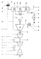
図面はコンビプラントを示し、これはガスタービンと、これの下流に接続された廃熱蒸気発生器と、この廃熱蒸気発生器から到来する蒸気により運転される蒸気タービンと、少なくとも1つの電気機械とから成る。
【0011】
図示のガスターボ装置団は逐次燃焼方式で構成されている。図示されていないが、種々の燃焼室の運転に必要な燃料の調整は例えばガスターボ装置団と協働する炭素ガス化により行われる。使用燃料を1次ネットワークから取り出すことが可能であるのは勿論である。ガスターボ装置団の運転のためのガス燃料がパイプラインを介して供給される場合には、1次ネットワークとコンシューマネットワークとの間の圧力差及び又は温度差に基づくポテンシャルがガスターボ装置団又は一般にサーキットの要求のために熱的に回収される。本ガスターボ装置団は、独立したユニットとして見なすと、圧縮機1と、これの下流に接続された第1の燃焼室2と、さらにこれの下流に接続された第1のタービン3と、さらにこれの下流に接続された第2の燃焼室4と、さらにこれの下流に接続された第2のタービン5とから構成されている。流体機械である圧縮機1と第1のタービン3と第2のタービン5は共通の1つのロータ軸12を有している。このロータ軸12は有利には圧縮機1のヘッド側と第2のタービン5の下流とに位置する図示されていない2つの軸受に支承されている。圧縮機1はその設計に応じて例えば比出力を高めるために図示されていない2つ又はそれ以上の部分圧縮機に分割されることができる。この種の構成では、第1の部分圧縮機の下流で第2の部分圧縮機の上流に中間冷却器が配置され、この中間冷却器内で部分圧縮空気が中間冷却される。同様に図示されていないこの中間冷却器内で回収された熱は最適に、要するに有効にプロセス内に戻し案内される。圧縮機1の吸込空気6は圧縮空気7となって、圧縮機出口と第1のタービン3とを囲む詳細には図示されていないケーシング内に流入する。このケーシング内には第1の燃焼室2も設けられており、この第1の燃焼室は有利には組み合わされた環状燃焼室として構成されている。当然ながら、圧縮空気7は図示されていないエアアキュムレータから第1の燃焼室2へ供給されてもよい。環状燃焼室はヘッド側でその周方向に分配された多数の詳細には図示されていないバーナを備えており、これらのバーナは有利には予混合バーナとして形成されている。この場合、ディフユージョンバーナが使用されることができる。この燃焼に由来する有害物質放出の削減、特にNOx放出の削減のために、本発明と同じ内容のヨーロッパ特許公開第0321809号明細書に基づく予混合バーナが設けられると有利であり、かつさらに同ヨーロッパ特許明細書に記載された燃料の供給形式が有利である。環状燃焼室として形成された第1の燃焼室の周方向に予混合バーナを配置することが望まれる場合、必要ならば同一バーナの一般的な構成を廃し、その代わりに種々異なる大きさの予混合バーナを使用することができる。このことは、例えばそれぞれ2つの大きな予混合バーナの間に、同一構造の小さな予混合バーナを配置することにより実現される。主バーナの機能を満たす大きな予混合バーナは、この燃焼室のパイロットバーナを形成する小さい予混合バーナに対して、この燃焼室を通流する燃焼空気、要するに圧縮機1から到来した圧縮空気に関連して、場合により固定することのできる寸法比を有することができる。燃焼室の全負荷運転範囲内でパイロットバーナは独立した予混合バーナとして作動し、その際、空気過剰率はほぼコンスタントに保たれる。主バーナの接続又は遮断はプラントに特有の所定の条件に基づいて行われる。パイロットバーナが全負荷運転範囲内で理想的な混合気で運転されることができるので、部分負荷運転の場合でもNOx放出は極めてわずかである。このような状況では、環状燃焼室としての第1の燃焼室2のフロント領域内の循環する流線がパイロットバーナの渦中心の極めて近くに位置し、その結果、これらのパイロットバーナにより点火が可能である。高負荷運転時には、パイロットバーナを介して供給される燃料量は、パイロットバーナがフル稼働されるまで、換言すれば全燃料量が供給されるまで増大される。このポイントがガスターボ装置団の負荷切り離し条件に対応するように設計が行われる。それ以上の出力増大は主バーナにより行われる。ガスターボ装置団のピーク負荷時には主バーナもフル稼働される。パイロットバーナにより誘発される「小さな」熱い渦中心の形成が、主バーナにより誘発される「大きな」冷えた渦中心の間で極めて不安定となるために、主バーナが貧で運転される場合ですら部分負荷運転範囲内では、NOx放出に対して付加的に低いCO放出及びUHC放出を伴う極めて良好な燃焼が生じ、換言すればパイロットバーナの熱い渦が直ちに主バーナの小さい渦内へ侵入する。第1の燃焼室2は個々の管状の多数の燃焼室から構成されることができるのは勿論であるが、、その場合には、これらの燃焼室は同様に斜め環状、場合により螺旋状にロータ軸を中心として配置される。環状燃焼室としての第1の燃焼室はその設計に無関係にロータの長さに実際になんの影響を及ぼさないようなジオメトリで配置される。この環状燃焼室から到来した熱ガス8は、環状燃焼室の直後に配置された第1のタービンに供給される。その熱量的に膨張する作用は意識的に最小に保たれ、換言すればこのタービン3は単に2列の回転羽根列から成っている。この種のタービンでは、軸方向スラストの安定化を目的とした端面における圧力補償が必要とされる。第1のタービン3内で部分膨張して第2の燃焼室4内へ流入する熱ガス9は前述した理由で著しく高い温度を有しており、有利にはこの熱ガスは確実に1000℃となるように運転技術的に設計される。この第2の燃焼室4はほぼ組み合わされた環状の軸方向又はある程度軸方向に延びる環状円筒の形状を有している。この燃焼室4は勿論軸方向又はある程度軸方向又は螺旋状に配置された自体閉鎖された多数の燃焼室から成ることもできる。1つの燃焼室から成る環状の燃焼室4のこの構成に関連して、この環状の円筒体には、周方向及び半径方向に、詳細には図示されていない多数の燃料ノズル管が配置されている。この燃焼室4はバーナを備えていない。第1のタービン3から到来した部分膨張した熱ガス9内に噴入された燃料の燃焼はこの箇所では自己着火で、温度レベルがこの種の運転形式を許容する限りにおいて行われる。燃焼室4がガス燃料、例えば天然ガスで運転されることを前提とすれば、部分膨張した熱ガス9の、第1のタービン3からの流出温度は依然として著しく高く、例えばすでに説明したように1000℃程度でなければならない。従って、燃焼室4内での天然ガスの自己着火を保証するためには、タービン3から到来した部分膨張した熱ガス9の流出温度は著しく高く、上述したように1000℃でなければならず、このことは部分負荷運転においても同じであり、このことはタービン2の設計上根本的な役割を果たす。自己着火が行われるように設計された燃焼室での運転確実性及び高い効率を保証するためには、火炎フロントが局部的に安定を保つことが極めて重要である。この目的のために、この燃焼室4内には、有利には内壁又は外壁のところに、詳細に図示されていない1列のエレメントが周方向に配置されており、このエレメントは軸方向で有利には燃料ノズル管の上流に配置されている。このエレメントの役割は、すでに述べた予混合バーナ内の逆流区域と同様な逆流区域を形成する渦を発生させることにある。この燃焼室4はその軸方向の配置及び全長に基づき高速燃焼室を形成している。この高速燃焼室では作動ガスの速度は大きくほぼ60m/sであるので、渦を発生するエレメントは流れと同形に形成されなければならない。このエレメントは向流側で有利には流れに向かった斜面を備えた四面体形状に形成されなければならない。渦を発生するこのエレメントは外面及び又は内面に配置されることができる。勿論、渦を発生するこのエレメントは軸方向で互いにずれていてもよい。渦を発生するこのエレメント(以下渦発生エレメント)の流出側の面はほぼ半径方向に形成されており、その結果、そこより下流に逆流区域が形成される。燃焼室4内での自己着火はガスターボ装置団の遷移的な負荷運転範囲並びに部分負荷運転範囲では確実性を保たねばならず、換言すれば燃料の噴入領域内でガス温度の変化が生じた場合でも燃焼室4内の自己着火を保証する補助手段が設けられなければならない。燃焼室4内へ噴入されたガス燃料の確実な自己着火を保証するために、この燃料に、比較的低い着火温度を有する別の燃料が少量だけ添加される。この「補助燃料」としては例えば燃料オイルが最適である。液体補助燃料は適当に噴入すれば、いわば火縄としての役目を果たし、かつ第1のタービン3から到来した部分膨張した熱ガス9の温度が、目標とする最適な1000℃のレベルを下回った場合でも、燃焼室4内での自己着火を可能ならしめる。自己着火の保証のために燃料オイルを添加するこの措置は、ガスターボ装置団が著しく減少した負荷で運転される場合にはいつでも特別に取り入れられる。この措置はさらに、燃焼室4が最小の軸方向長さを有することができるための決定的な役割を果たす。燃焼室4の短い全長、火炎安定化のための渦発生エレメントの作用及び自己着火の継続的な確実性は、迅速な燃焼と、熱い火炎フロントの領域内での燃料の最小の滞留時間とを得るための要因である。このことから結果する燃焼技術的に測定可能な直接的な効果は、NOx放出がもはや問題を残さないほどに削減されることである。この前提条件はさらに、燃焼の場所を規定することを可能にし、このことにより、この燃焼室4の構造体を最適に冷却することができる。燃焼室4内で生成された熱ガス10は次いで下流の第2のタービン5に供給される。ガスターボ装置団の熱力学的な特性値は、第2のタービン5から到来した排ガスが、図示された蒸気回路を運転することができるような熱的なポテンシャルを有するように設計されることができる。環状燃焼室として形成された第1の燃焼室2についてすでに説明したように、この燃焼室は実際上ガスターボ装置団のロータ長さになんら影響を及ぼさないようなジオメトリで配置される。さらに、第1のタービン3の流出平面と第2のタービン5の向流平面との間に延びる第2の燃焼室4は最小の長さを有するように決定されることができる。第1のタービン3内での熱ガスの膨張が上述の理由でわずかな数の回転羽根列を介して行われるので、ガスターボ装置団のロータ軸12がその短い長さに基づき技術的に2つの軸受で充分支持可能となるようにガスターボ装置団を構成することができる。ロータ軸12はタービン5側に、蒸気タービン14とガスターボ装置団とを連結するクラッチ13を備えている。流体機械の出力伝達は、圧縮機側に連結された、起動モータとしても役立つことのできる発電機15を介して行われる。第2のタービン5内での膨張後でも依然として高い熱量的なポテンシャルを有する排ガス11は廃熱蒸気発生器20内へ流入し、この廃熱蒸気発生器内で熱交換法により蒸気が発生させられる。この蒸気は下流に接続された蒸気回路の作動媒体を形成する。熱量的に利用し尽くされた排ガスは次いで煙道ガス32として大気中に放出される。図示の廃熱蒸気発生器20はドラム21を備えたシングルプレッシャ方式で形成されている。勿論、マルチプレッシャ方式の廃熱蒸気発生器を設けることも可能である。エコノマイザ20a、低圧蒸気段20b及び過熱蒸気段20cを介して、前述のドラム21との協働により高圧蒸気28が発生させられる。この高圧蒸気28は次いで蒸気タービン14に供給される。膨張した蒸気23は水冷式又は空冷式の復水器16内で復水される。この復水器16の下流で作動する復水ポンプ17により、復水24は供給水容器兼用脱気装置18内へ搬送される。下流で作動する搬送ポンプ19は水25を廃熱蒸気発生器20のエコノマイザ20a内に圧送し、これにより、循環が改めて繰り返される。廃熱蒸気発生器20は中間過熱器22により拡張されており、この中間過熱器はそれぞれの廃熱蒸気発生器20と協働するか又は独立して運転される。このことの可能性が図面に示されている。すなわち、燃焼空気29が燃料30と混合され、それに続く燃焼により形成された熱ガス31が廃熱蒸気発生器20内へ案内され、この廃熱蒸気発生器内ですでに述べた蒸気発生が行われる。発電所設備、換言すればガスターボ装置団が停止状態から始動されなければならない場合、中間過熱器22が点火される。すでに説明した回路を介して形成された蒸気量が蒸気タービン14に供給される。この蒸気タービンはこれに連結されたガスターボ装置団の始動出力を提供する。タービン5から到来した排ガス11により発生させられた蒸気28がガスターボ装置団の運転の維持を可能ならしめるやいなや、中間過熱器22が運転停止される。ガスターボ装置団と蒸気タービン14との間の連結が何らかの理由で行われない場合には、第1の蒸気量により蒸気タービン14内で発生した電流がガスターボ装置団の始動のために使用される。このような事態が生じた場合にはこの目的のために付加的な電気機械が必要である。
【図面の簡単な説明】
【図1】ガスタービンと、これの下流に接続された廃熱蒸気発生器と、この廃熱蒸気発生器から到来する蒸気により運転さる蒸気タービンと、少なくとも1つの電気機械とから成る本発明の1実施例のコンビプラントを示す図である。
【符号の説明】
1 圧縮機、2 第1の燃焼室、 3 第1のタービン、 4 第2の燃焼室、 5 第2のタービン、 6 吸込空気、 7 圧縮空気、 8 熱ガス、 9 部分膨張した熱ガス、 10 熱ガス、 11 排ガス、 12 ロータ軸、 13 クラッチ、 14 蒸気タービン、 15 電気機械(発電機)、 16 復水器、 17 搬送ポンプ、 18 供給水容器兼用脱気装置、 19搬送ポンプ、 20 廃熱蒸気発生器、 20a エコノマイザ、 20b 低圧蒸気タービン、 20c 過熱蒸気段、 21 ドラム、 22 中間過熱器、 23 膨張した蒸気、 24 復水、 25 水、 28 高圧蒸気、 29 燃焼空気、 30 燃料、 31 熱ガス、 32 煙道ガス[0001]
BACKGROUND OF THE INVENTION
The present invention mainly relates to a method for operating a power station comprising a gas turbo equipment group, a steam circuit, and a steam turbine.
[0002]
[Prior art]
In a power plant installation with a gas turbocharger team, the start of the gas turbocharger team (black start) may cause some difficulties for theoretical reasons with respect to obtaining the required current. This difficulty arises whenever the power plant equipment is operated in island mode and must be started up accordingly within this infrastructure. Therefore, this type of power plant equipment must not require a significantly large electrical output at start-up. This is because such a large electrical output can only be obtained via an additional independent current generating machine. For small or medium-sized gas turbochargers, the starting power required for this can be easily obtained with a typical auxiliary current generator, but if a relatively large gas turbocharger must be started, The required starting power increases rapidly, so an auxiliary device must be provided that requires a high proportion of costs that tend to be disproportionate to the overall plant costs of the power plant. There is a risk that this type of peak current cannot be easily received from the power supply network, even if the gas turbocharger group can obtain the required starting power via the composite current supply. Further, in a modern power plant facility having a specific output of 150 MWe or more and operating in a sequential combustion system (sequentielle Verbrennung) and having a single-shaft rotor shaft, the required starting power is large, approximately 15 MVA. Under such conditions, the adoption of this type of power plant equipment does not ultimately depend on the presence of electrical infrastructure. In the absence of infrastructure or when there is insufficient infrastructure, the commercial potential of this type of power plant equipment is first limited. It is economically meaningless to obtain a starting output from a stopped state through, for example, a diesel drive motor.
[0003]
[Problems to be solved by the invention]
An object of the present invention is to provide a self-solving means capable of obtaining a starting output necessary for operation of a gas turbo device group in the operation method described at the beginning.
[0004]
[Means for Solving the Problems]
According to the present invention, the above-described object is to generate a first steam quantity in connection with the steam circuit to generate an output for starting the gas turbocharger unit, as defined in claim 1, and this steam quantity. Is supplied to the steam turbine, and the output resulting from the supply of this amount of steam to the steam turbine is transmitted directly or indirectly to the gas turbo unit to provide the required starting power.
[0005]
【The invention's effect】
The main advantage of the present invention is that the steam generation that takes place in connection with the gas turbocharger group is directly or indirectly used for starting the gas turbocharger group inside the power plant installation. The starting condition in this case is that a simple gas turbocharger group in which the exhaust gas potential coming from the last turbine is discarded without being used, in other words, this exhaust gas is guided into the chimney is operated today. That is not. In modern times, this high-power gas turbine is operated as a combined plant, a so-called combination plant, or steam is generated downstream of the gas turbo equipment group by making full use of the calorimetric potential of this exhaust gas. It is used to cool devices that are subjected to mechanical stress or to increase the specific power of a gas turbomachinery. Furthermore, within the framework of the present invention, the waste heat steam generator can often be provided with an additional combustion device.
[0006]
This starting condition therefore offers the possibility of obtaining a starting power with the first steam quantity. The simplest circuit for this is obtained when the power plant equipment is designed as a combination plant. This is because in this case the steam turbine is operated anyway. In this case, a first steam quantity is first generated via an additional combustion device of the waste heat steam generator and this steam quantity is supplied to the steam turbine. The gas turbomachinery is started via a mechanical direct drive or an acquired electrical output. In the absence of a waste heat steam generator, the infrastructure is used for steam generation, in which case the required steam turbine is also designed for the minimum required starting power. be able to.
[0007]
Advantageous and effective configurations according to the invention are described in the other claims.
[0008]
DETAILED DESCRIPTION OF THE INVENTION
Next, embodiments of the present invention will be described with reference to the drawings.
[0009]
The drawing omits all elements that are not necessary for a direct understanding of the invention. The direction of media flow is indicated by arrows.
[0010]
The drawing shows a combined plant, which is a gas turbine, a waste heat steam generator connected downstream thereof, a steam turbine operated by steam coming from the waste heat steam generator, and at least one electric machine It consists of.
[0011]
The illustrated gas turbo device group is configured by a sequential combustion method. Although not shown, adjustment of fuel necessary for operation of various combustion chambers is performed by, for example, carbon gasification in cooperation with a gas turbo device group. Of course, it is possible to take out the used fuel from the primary network. When gas fuel for operation of the gas turbo unit is supplied via a pipeline, the potential based on the pressure difference and / or temperature difference between the primary network and the consumer network is Recovered thermally on demand. When this gas turbo device group is regarded as an independent unit, the compressor 1, the first combustion chamber 2 connected downstream thereof, the first turbine 3 connected further downstream thereof, and further this The second combustion chamber 4 is connected to the downstream of the second combustion chamber 4 and the second turbine 5 is further connected to the downstream of the second combustion chamber 4. The compressor 1, the first turbine 3, and the second turbine 5, which are fluid machines, have a common rotor shaft 12. The rotor shaft 12 is preferably supported on two bearings (not shown) located on the head side of the compressor 1 and downstream of the second turbine 5. Depending on its design, the compressor 1 can be divided into two or more partial compressors not shown, for example to increase the specific power. In this type of configuration, an intermediate cooler is disposed downstream of the first partial compressor and upstream of the second partial compressor, and the partially compressed air is intercooled in the intermediate cooler. Similarly, the heat recovered in this intercooler, not shown, is optimally and effectively returned to the process. The intake air 6 of the compressor 1 becomes compressed air 7 and flows into a casing (not shown in detail) surrounding the compressor outlet and the first turbine 3. A first combustion chamber 2 is also provided in the casing, which is preferably configured as a combined annular combustion chamber. Of course, the compressed air 7 may be supplied to the first combustion chamber 2 from an air accumulator (not shown). The annular combustion chamber is provided with a number of burners, not shown in detail, distributed in the circumferential direction on the head side, these burners being preferably formed as premix burners. In this case, a diffusion burner can be used. In order to reduce the emission of harmful substances derived from this combustion, in particular NOx emission, it is advantageous if a premix burner according to EP 0 321 809 of the same content as the present invention is provided, and furthermore the same The fuel supply type described in the European patent specification is advantageous. If it is desired to arrange the premix burner in the circumferential direction of the first combustion chamber formed as an annular combustion chamber, the general configuration of the same burner is eliminated if necessary, and instead different sizes of pre-burners are used. Mixing burners can be used. This is achieved, for example, by placing a small premix burner of the same structure between each two large premix burners. A large premix burner that fulfills the function of the main burner is related to the combustion air flowing through the combustion chamber, in other words, the compressed air coming from the compressor 1, relative to the small premix burner forming the pilot burner of the combustion chamber. Thus, it can have a dimensional ratio that can be fixed in some cases. Within the full load operating range of the combustion chamber, the pilot burner operates as an independent premix burner, with the excess air ratio being kept substantially constant. The main burner is connected or disconnected based on predetermined conditions specific to the plant. Since the pilot burner can be operated with an ideal mixture within the full load operating range, NOx emissions are very small even in partial load operation. In such a situation, the circulating streamline in the front region of the first combustion chamber 2 as an annular combustion chamber is located very close to the vortex center of the pilot burner, so that these pilot burners can be ignited. It is. During high load operation, the amount of fuel supplied via the pilot burner is increased until the pilot burner is fully operated, in other words, until the total amount of fuel is supplied. The design is performed so that this point corresponds to the load separation condition of the gas turbo device group. Further power increase is performed by the main burner. At the peak load of the gas turbo equipment group, the main burner is also fully operational. When the main burner is operated poorly because the formation of a “small” hot vortex center induced by the pilot burner becomes extremely unstable between the “large” cold vortex centers induced by the main burner In the partial load operating range, very good combustion with low CO emissions and UHC emissions occurs in addition to NOx emissions, in other words, the hot vortex of the pilot burner immediately enters the small vortex of the main burner. . The first combustion chamber 2 can of course be composed of a number of individual tubular combustion chambers, but in this case, these combustion chambers are likewise obliquely annular, in some cases spiral. Arranged around the rotor shaft. The first combustion chamber as an annular combustion chamber is arranged with a geometry that does not actually affect the length of the rotor, regardless of its design. The hot gas 8 coming from the annular combustion chamber is supplied to a first turbine disposed immediately after the annular combustion chamber. The thermal expansion effect is consciously kept to a minimum, in other words, the turbine 3 is simply composed of two rows of rotating blades. This type of turbine requires pressure compensation at the end face for the purpose of stabilizing axial thrust. The hot gas 9 that partially expands in the first turbine 3 and flows into the second combustion chamber 4 has a remarkably high temperature for the reasons described above, and advantageously this hot gas is reliably 1000 ° C. It is designed in terms of driving technology. The second combustion chamber 4 has a substantially combined annular axial direction or annular cylindrical shape extending in a certain axial direction. The combustion chamber 4 can of course also consist of a number of closed combustion chambers arranged axially or to some extent axially or spirally. In connection with this configuration of the annular combustion chamber 4 consisting of one combustion chamber, the annular cylinder is provided with a number of fuel nozzle tubes not shown in detail in the circumferential direction and in the radial direction. Yes. This combustion chamber 4 does not have a burner. The combustion of the fuel injected into the partially expanded hot gas 9 coming from the first turbine 3 is self-igniting at this point, as long as the temperature level allows this type of operation. Assuming that the combustion chamber 4 is operated with gas fuel, for example natural gas, the exit temperature of the partially expanded hot gas 9 from the first turbine 3 is still very high, for example 1000 as already explained. Must be around ℃. Therefore, in order to guarantee the self-ignition of natural gas in the combustion chamber 4, the outflow temperature of the partially expanded hot gas 9 coming from the turbine 3 is remarkably high and must be 1000 ° C. as described above. This is the same in part load operation, which plays a fundamental role in the design of the turbine 2. In order to ensure operational certainty and high efficiency in a combustion chamber designed for self-ignition, it is very important that the flame front be kept locally stable. For this purpose, in this combustion chamber 4 a row of elements, not shown in detail, are arranged circumferentially, preferably on the inner or outer wall, which elements are advantageously axial. Is arranged upstream of the fuel nozzle tube. The role of this element is to generate vortices that form a backflow area similar to the backflow area in the premixed burner already described. The combustion chamber 4 forms a high-speed combustion chamber based on its axial arrangement and overall length. In this high-speed combustion chamber, the working gas has a large velocity of approximately 60 m / s, so that the element that generates the vortex must be formed in the same shape as the flow. This element must be formed in the shape of a tetrahedron, preferably with a slope facing the flow on the countercurrent side. This element generating vortices can be arranged on the outer and / or inner surface. Of course, the elements generating vortices may be offset from one another in the axial direction. The surface on the outflow side of this element that generates vortices (hereinafter referred to as vortex generating elements) is formed in a substantially radial direction, and as a result, a backflow area is formed downstream thereof. The self-ignition in the combustion chamber 4 must maintain certainty in the transitional load operation range and partial load operation range of the gas turbo equipment group, in other words, a change in gas temperature occurs in the fuel injection region. Even in such a case, auxiliary means for assuring self-ignition in the combustion chamber 4 must be provided. In order to ensure reliable self-ignition of the gaseous fuel injected into the combustion chamber 4, a small amount of another fuel having a relatively low ignition temperature is added to this fuel. As this “auxiliary fuel”, for example, fuel oil is optimal. If the liquid auxiliary fuel is properly injected, it serves as a fire rope, and the temperature of the partially expanded hot gas 9 coming from the first turbine 3 falls below the target optimal 1000 ° C. level. Even in this case, self-ignition in the combustion chamber 4 is made possible. This measure of adding fuel oil to ensure self-ignition is specifically incorporated whenever the gas turbo unit is operated at a significantly reduced load. This measure further plays a decisive role for the combustion chamber 4 to have a minimum axial length. The short overall length of the combustion chamber 4, the action of the vortex generating elements for flame stabilization and the continued certainty of self-ignition ensure rapid combustion and the minimum residence time of the fuel in the region of the hot flame front. It is a factor to get. The direct combustion measurable effect that results from this is that NOx emissions are reduced so that they no longer leave problems. This precondition further makes it possible to define the location of the combustion, whereby the structure of this combustion chamber 4 can be optimally cooled. The hot gas 10 generated in the combustion chamber 4 is then supplied to the second turbine 5 downstream. The thermodynamic characteristic values of the gas turbo device group can be designed so that the exhaust gas coming from the second turbine 5 has a thermal potential such that the steam circuit shown can be operated. . As already described for the first combustion chamber 2 formed as an annular combustion chamber, this combustion chamber is arranged in such a geometry that practically does not affect the rotor length of the gas turbomachinery. Furthermore, the second combustion chamber 4 extending between the outflow plane of the first turbine 3 and the countercurrent plane of the second turbine 5 can be determined to have a minimum length. Since the expansion of the hot gas in the first turbine 3 takes place via a small number of rotating blade rows for the reasons mentioned above, the rotor shaft 12 of the gas turbomachinery group is technically The gas turbo device group can be configured to be sufficiently supported by the bearing. The rotor shaft 12 includes a clutch 13 on the turbine 5 side for connecting the steam turbine 14 and the gas turbo device group. The power transmission of the fluid machine takes place via a generator 15 connected to the compressor side, which can also serve as a starter motor. Even after expansion in the second turbine 5, the exhaust gas 11 still having a high calorimetric potential flows into the waste heat steam generator 20, and steam is generated in the waste heat steam generator by a heat exchange method. . This steam forms the working medium of the steam circuit connected downstream. The exhaust gas exhausted calorifically is then released into the atmosphere as flue gas 32. The illustrated waste heat steam generator 20 is formed by a single pressure system having a drum 21. Of course, it is also possible to provide a waste heat steam generator of the pressure type. High-pressure steam 28 is generated in cooperation with the drum 21 through the economizer 20a, the low-pressure steam stage 20b, and the superheated steam stage 20c. This high pressure steam 28 is then supplied to the steam turbine 14. The expanded steam 23 is condensed in a water-cooled or air-cooled condenser 16. The condensate 24 is transported into the supply water container / deaerator 18 by a condensate pump 17 operating downstream of the condenser 16. The transport pump 19 operating downstream feeds the water 25 into the economizer 20a of the waste heat steam generator 20, whereby the circulation is repeated again. The waste heat steam generator 20 is extended by an intermediate superheater 22, which cooperates with each waste heat steam generator 20 or operates independently. This possibility is shown in the drawing. That is, the combustion air 29 is mixed with the fuel 30, and the hot gas 31 formed by the subsequent combustion is guided into the waste heat steam generator 20, and the steam generation already described in the waste heat steam generator is performed. Is called. The intermediate superheater 22 is ignited when the power plant equipment, in other words the gas turbo device group, has to be started from a stopped state. The amount of steam formed through the circuit already described is supplied to the steam turbine 14. This steam turbine provides the starting output of a gas turbomachinery coupled thereto. As soon as the steam 28 generated by the exhaust gas 11 coming from the turbine 5 makes it possible to maintain the operation of the gas turbo device group, the intermediate superheater 22 is shut down. If the connection between the gas turbo device group and the steam turbine 14 is not made for some reason, the current generated in the steam turbine 14 by the first steam amount is used to start the gas turbo device group. When this happens, an additional electrical machine is required for this purpose.
[Brief description of the drawings]
FIG. 1 shows an embodiment of the invention comprising a gas turbine, a waste heat steam generator connected downstream thereof, a steam turbine operated by steam coming from the waste heat steam generator, and at least one electric machine. It is a figure which shows the combination plant of 1 Example.
[Explanation of symbols]
DESCRIPTION OF SYMBOLS 1 Compressor, 2 1st combustion chamber, 3 1st turbine, 4 2nd combustion chamber, 5 2nd turbine, 6 Intake air, 7 Compressed air, 8 Hot gas, 9 Partially expanded hot gas, 10 Hot gas, 11 exhaust gas, 12 rotor shaft, 13 clutch, 14 steam turbine, 15 electric machine (generator), 16 condenser, 17 transport pump, 18 supply water container deaerator, 19 transport pump, 20 waste heat Steam generator, 20a economizer, 20b low pressure steam turbine, 20c superheated steam stage, 21 drum, 22 intermediate superheater, 23 expanded steam, 24 condensate, 25 water, 28 high pressure steam, 29 combustion air, 30 fuel, 31 heat Gas, 32 flue gas