JP3860552B2 - Imaging device - Google Patents
Imaging device Download PDFInfo
- Publication number
- JP3860552B2 JP3860552B2 JP2003083928A JP2003083928A JP3860552B2 JP 3860552 B2 JP3860552 B2 JP 3860552B2 JP 2003083928 A JP2003083928 A JP 2003083928A JP 2003083928 A JP2003083928 A JP 2003083928A JP 3860552 B2 JP3860552 B2 JP 3860552B2
- Authority
- JP
- Japan
- Prior art keywords
- image
- photographed
- photographing
- unit
- guidance
- Prior art date
- Legal status (The legal status is an assumption and is not a legal conclusion. Google has not performed a legal analysis and makes no representation as to the accuracy of the status listed.)
- Expired - Fee Related
Links
Images


Classifications
-
- H—ELECTRICITY
- H04—ELECTRIC COMMUNICATION TECHNIQUE
- H04N—PICTORIAL COMMUNICATION, e.g. TELEVISION
- H04N23/00—Cameras or camera modules comprising electronic image sensors; Control thereof
- H04N23/60—Control of cameras or camera modules
- H04N23/64—Computer-aided capture of images, e.g. transfer from script file into camera, check of taken image quality, advice or proposal for image composition or decision on when to take image
-
- H—ELECTRICITY
- H04—ELECTRIC COMMUNICATION TECHNIQUE
- H04N—PICTORIAL COMMUNICATION, e.g. TELEVISION
- H04N23/00—Cameras or camera modules comprising electronic image sensors; Control thereof
- H04N23/60—Control of cameras or camera modules
- H04N23/63—Control of cameras or camera modules by using electronic viewfinders
- H04N23/633—Control of cameras or camera modules by using electronic viewfinders for displaying additional information relating to control or operation of the camera
- H04N23/634—Warning indications
Description
【0001】
【発明の属する技術分野】
本発明は、物体を撮影する撮影装置に係わり、特に、被撮影物体を適切な位置または状態に誘導する機能を備えた撮影装置に係わる。
【0002】
【従来の技術】
撮影装置を用いて物体を撮影し、その撮影により得られた画像を利用してその物体を識別する技術は知られている。(例えば、特許文献1参照。)
特許文献1に記載のシステムは、カメラおよびそのカメラで撮影した画像を表示する表示装置を備える。そして、表示装置には、カメラにより撮影された撮影対象物の画像、および撮影対象物が適切な位置に配置された状態で撮影されたならば得られるであろう画像の輪郭(基準輪郭)を、重ね合わせて表示する。これにより、ユーザは、撮影対象物の位置を修正することができ、適切な位置に配置された状態でその撮影対象物の画像を得ることができる。
【0003】
また、カメラを用いて撮影された物体の画像をもとにその物体を所定の位置に誘導する技術も知られている。(例えば、特許文献2参照。)
ただし、特許文献2に記載のシステムは、駐車場等に設けられ、撮影された画像から自動車が検出されたときに、メッセージの表示やランプの点滅等を利用して、その自動車を所定の経路に沿って目的地に誘導するものである。即ち、このシステムは、最適な撮影を行える位置に被撮影物体を誘導するものではない。
【0004】
【特許文献1】
特開2001−273498号公報(図12〜図14、段落0070〜0073参照)
【特許文献2】
特開昭64−55674号公報(第2ページ)
【0005】
【発明が解決しようとする課題】
特許文献1に記載の方法では、ユーザが、表示装置に表示された基準輪郭を見ながら撮影対象物の位置を修正することになる。すなわち、この方法では、基準輪郭および撮影画像を表示するための表示装置が必須要件となる。
【0006】
また、この方法では、ユーザは、撮影対象物を撮影のための適切な位置に移動させることは可能であるが、その物体が撮影のために好適な姿勢になっているか否かを確認することはできない。ここで、「姿勢」とは、その物体のカメラに対する角度または傾きを含む概念である。
【0007】
本発明の目的は、撮影装置で物体を撮影することにより得られる画像を利用してその物体を識別する際の識別精度を向上させることである。また、被撮影物体を適切な位置または姿勢に誘導することである。
【0008】
【課題を解決するための手段】
本発明の撮影装置は、物体を撮影する撮影手段、上記物体の目標撮影状態を表す目標撮影状態情報を記憶する目標撮影状態記憶手段、上記目標撮影状態情報および上記撮影手段により撮影された画像に基づいて上記物体をどのように誘導すべきかを判定する誘導判定手段、上記誘導判定手段による判定結果に基づいて上記物体をどのように誘導すべきかを指示する誘導指示出力手段、上記撮影手段により撮影された画像を出力する画像出力手段、を有する。
【0009】
この撮影装置においては、実際に撮影された画像の状態と目標撮影状態とを比較することにより、その物体をどのように誘導すべきかが判定される。そして、その判定結果に基づいて上記物体をどのように誘導すべきかの指示がされる。よって、その誘導指示に従って上記物体を移動または回転させれば、上記物体の状態を、目標撮影状態に近づけることができる。この結果、目的に応じた良好な画像が得られる。
【0010】
上記撮影装置において、目標撮影状態情報として上記物体の目標位置を定義しておき、誘導判定手段が上記物体を誘導すべき方向を判定するようにしてもよい。この場合、上記物体が目標位置に誘導されて撮影されるので、良好な画像が得られる。
【0011】
また、上記撮影装置において、目標撮影状態情報として上記物体の目標姿勢を定義しておき、誘導判定手段が上記物体を誘導すべき回転方向を判定するようにしてもよい。この場合、上記物体が目標姿勢に誘導されて撮影されるので、良好な画像が得られる。
【0012】
本発明の他の態様の撮影装置は、撮影手段、上記撮影手段を用いて背景画像を撮影した場合の目標撮影状態を表す目標撮影状態情報を記憶する目標撮影状態記憶手段、上記目標撮影状態情報および上記撮影手段により撮影された画像に基づいて上記撮影手段を誘導すべき方向または角度を判定する誘導判定手段、上記誘導判定手段による判定結果に基づいて上記撮影手段を誘導すべき方向または角度を指示する誘導指示出力手段、を有する。
【0013】
この撮影装置においては、撮影手段の位置または角度が最適化されるので、良好な背景画像が得られ、撮影した画像から被撮影物体の画像を正確に切り出すことが可能となる。
【0014】
【発明の実施の形態】
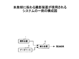
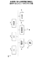
図1は、本発明に係わる撮影装置が使用されるシステムの一実施例の構成図である。このシステムは、物体を撮影する撮影装置1、1または複数の物体の画像データが登録されるデータベース2、撮影装置1により撮影された画像とデータベース2に登録されている各画像とを比較することにより、撮影装置1により撮影された物体を識別する(あるいは、撮影装置1により撮影された物体がデータベース2に登録されているか否かを判別する)識別装置3を備える。
【0015】
このシステムにおいて識別精度を向上させるためには、物体を撮影する際に、その物体が適切な位置に適切な姿勢で配置されている必要がある。従って、本発明に係わる撮影装置は、撮影対象の物体を適切な位置および姿勢に誘導する機能を備えている。そして、このシステムのユーザは、上記誘導に従って物体を移動させたり、あるいはその物体を回転させたりすることができる。なお、「物体の姿勢」とは、その物体のカメラに対する角度または傾きを含む概念である。
【0016】
図2は、第1の実施形態の撮影装置の構成図である。第1の実施形態の撮影装置10は、撮影部11、撮影画像記憶部12、目標撮影状態記憶部13、誘導方向判定部14、誘導方向指示出力部15、および撮影画像出力制御部16を備える。
【0017】
撮影部11は、カメラであり、撮影した画像の画像データを出力する。なお、この画像データは、特に限定されるものではないが、例えば、ビットマップ形式のデジタルデータである。撮影画像記憶部12は、撮影部11から出力される画像データを記憶する。
【0018】
目標撮影状態記憶部13は、被撮影物体の目標撮影状態を表す目標撮影状態情報を記憶する。ここで、目標撮影状態情報は、撮影時に被撮影物体を配置すべき目標位置を表す情報を含む。なお、目標位置とは、被撮影物体がその位置に配置された状態で撮影されたならばその物体の特徴を十分に検出できるような位置をいう。この場合、目標撮影状態情報は、被撮影物体またはそれと同等な物体を目標位置に配置させた状態で撮影することによって予め得られる画像データであってもよい。
【0019】
誘導方向判定部14は、目標撮影状態情報を参照し、撮影部11により撮影された被撮影物体が適切な位置に配置されているか否かを判定すると共に、被撮影物体が適切な位置に配置されていない場合には、被撮影物体をどの方向に誘導すべきか、を判定する。なお、誘導方向判定部14は、撮影画像記憶部12に記憶されている画像データを解析してその特徴を抽出する特徴抽出部17を備え、特徴抽出部17の出力に基づいて被撮影物体を認識できるものとする。
【0020】
誘導方向指示出力部15は、誘導方向判定部14による判定結果をユーザに通知する。すなわち、被撮影物体が適切な位置に配置されていた場合には、その旨をユーザに通知する。一方、被撮影物体が適切な位置に配置されていなかった場合には、被撮影物体を移動すべき方向をユーザに提示する。これにより、ユーザは、被撮影物体を撮影のための適切な位置に配置することができる。
【0021】
撮影画像出力制御部16は、撮影画像記憶部12に記憶されている画像データを出力する。ここで、この画像データは、例えば、図1に示す識別装置3に送られる。なお、撮影画像出力制御部16は、誘導方向判定部14によって被撮影物体が適切な位置に配置されていると判定された場合にのみ、撮影画像記憶部12に記憶されている画像データを出力するようにしてもよい。即ち、被撮影物体が適切な位置に配置されていると判定された場合には、その状態で撮影されたときの画像は、被撮影物体を識別するために十分に良好な画像であると見込まれるので、その場合に限ってその画像データが識別装置3に送られるようにすれば、識別精度の向上が図れる。
【0022】
次に、図3〜図5を参照しながら、第1の実施形態の撮影装置10の動作を説明する。なお、ここでは、目標撮影状態記憶部13には、目標撮影状態情報として、被撮影物体またはそれと同等な物体を目標位置に配置させた状態で撮影することによって得られた目標画像が予め記憶されているものとする。
【0023】
図3に示す例では、被撮影物体が目標位置から上方にずれた位置に配置されている。この場合、まず、撮影部11により得られた撮影画像が撮影画像記憶部12に記憶される。続いて、誘導方向判定部14は、撮影画像記憶部12に記憶されている撮影画像と、目標撮影状態情報として目標撮影状態記憶部13に登録されている目標画像とを比較する。この結果、被撮影物体が目標位置に対して上方にずれた位置に配置されていることが検出される。そして、誘導方向指示出力部15は、誘導方向判定部14による検出結果を出力する。具体的には、例えば、「下方向に移動させてください。」というメッセージが出力される。
【0024】
図4に示す例では、被撮影物体が撮影部11に近づきすぎている。この場合、撮影画像記憶部12に記憶されている撮影画像と、目標撮影状態記憶部13に登録されている目標画像とを比較すると、撮影画像の中に写っている被撮影物体が目標画像の中に写っている被撮影物体よりも大きいことが検出される。これにより、誘導方向判定部14は、被撮影物体が撮影部11に近づきすぎていることを検出する。そして、誘導方向指示出力部15は、誘導方向判定部14による検出結果を出力する。具体的には、例えば、「カメラから遠ざけてください。」というメッセージが出力される。
【0025】
図5に示す例では、被撮影物体が撮影部11から離れすぎている。この場合、撮影画像記憶部12に記憶されている撮影画像と、目標撮影状態記憶部13に登録されている目標画像とを比較すると、撮影画像の中に写っている被撮影物体が目標画像の中に写っている被撮影物体よりも小さいことが検出される。これにより、誘導方向判定部14は、被撮影物体が撮影部11から離れすぎていることを検出する。そして、誘導方向指示出力部15は、誘導方向判定部14による検出結果を出力する。具体的には、例えば、「カメラに近づけてください。」というメッセージが出力される。
【0026】
このように、第1の実施形態の撮影装置10は、被撮影物体が目標位置からずれた位置に配置されていた場合には、その被撮影物体を目標位置に誘導するメッセージを出力する。これにより、ユーザは、容易に被撮影物体を目標位置に移動させることができる。この結果、その物体が良好な状態で撮影された画像が得られるので、物体の識別精度が向上する。
【0027】
図6は、第1の実施形態の撮影装置10の動作を示すフローチャートである。なお、目標撮影状態記憶部13には、予め目標撮影状態情報が登録されているものとする。
【0028】
ステップS1では、まず、撮影部11が撮影を行う。そして、撮影部11により撮影された画像が撮影画像記憶部12に記憶される。ステップS2では、撮影画像記憶部12に記憶された画像を解析することにより、「現在の撮影状態」を算出する。なお、「撮影状態」とは、図3〜図5に示す例では、被撮影物体の位置を意味する。
【0029】
ステップS3、S4では、ステップS2で得られた「現在の撮影状態」と目標撮影状態記憶部13に記憶されている「目標撮影状態」とを比較する。なお、図3〜図5に示す例では、画像内における被撮影物体の位置や大きさ等が比較される。そして、「現在の撮影状態」が「目標撮影状態」の範囲内であった場合は、被撮影物体が目標位置に配置されているものとみなし、誘導処理を終了する。一方、「現在の撮影状態」が「目標撮影状態」の範囲内でなかった場合には、被撮影物体が目標位置に配置されていないものとみなし、ステップS5〜S6の誘導処理を実行する。
【0030】
ステップS5では、被撮影物体を誘導すべき方向を決定する。ここで、誘導方向は、「「現在の撮影状態」を「目標撮影状態」に近づけるような方向」として算出される。なお、具体例については、図3〜図5を参照しながら説明した通りである。そして、ステップS6において、ユーザに対して誘導方向を通知するためのメッセージを出力する。これにより、ユーザは、被撮影物体を目標位置に近づけることができる。この後、ステップS1に戻り、次の画像を撮影する。
【0031】
上記フローチャートの処理は、被撮影物体が目標位置に配置されるまで繰り返し実行される。そして、被撮影物体が目標位置に配置された時点で誘導処理は終了する。
【0032】
図7は、第2の実施形態の撮影装置の構成図である。第1の実施形態の撮影装置20は、撮影部11、撮影画像記憶部12、目標撮影状態記憶部21、誘導姿勢判定部22、誘導姿勢指示出力部23、および撮影画像出力制御部16を備える。なお、撮影部11、撮影画像記憶部12、撮影画像出力制御部16については、第1の実施形態において説明した通りである。
【0033】
目標撮影状態記憶部21は、被撮影物体の目標撮影状態を表す目標撮影状態情報を記憶する。ここで、この目標撮影状態情報は、撮影時における被撮影物体の目標姿勢を表す情報を含む。なお、目標姿勢とは、被撮影物体がその姿勢で撮影されたならばその物体の特徴を十分に検出できるような姿勢をいう。この場合、目標撮影状態情報は、被撮影物体またはそれと同等な物体を目標姿勢にさせた状態で撮影することにより予め得られる画像データであってもよい。
【0034】
誘導姿勢判定部22は、目標撮影状態情報を参照し、撮影部11により撮影された被撮影物体が適切な姿勢であるか否かを判定すると共に、被撮影物体が適切な姿勢でなかった場合には、被撮影物体をどのように回転させるのか、を判定する。なお、誘導姿勢判定部22は、撮影画像記憶部12に記憶されている画像データを解析してその特徴を抽出する特徴抽出部17を備え、特徴抽出部17の出力に基づいて被撮影物体の姿勢を認識できるものとする。
【0035】
誘導姿勢指示出力部23は、誘導姿勢判定部22による判定結果をユーザに通知する。すなわち、被撮影物体が適切な姿勢であった場合には、その旨をユーザに通知する。一方、被撮影物体が適切な姿勢でなかった場合には、被撮影物体を回転させるべき方向および回転量をユーザに提示する。これにより、ユーザは、被撮影物体を撮影のために適切な姿勢に修正することができる。
【0036】
次に、図8〜図9を参照しながら、第2の実施形態の撮影装置20の動作を説明する。
図8に示す例では、被撮影物体の形状が立方体であるものとする。また、目標撮影状態記憶部21には、目標撮影状態情報として、被撮影物体またはそれと同等な物体を目標姿勢にした状態で撮影することにより得られた目標画像が予め記憶されているものとする。この例では、立方体のある一面がカメラに向いている状態が目標姿勢である。したがって、目標画像の中に写っている物体の形状は、正方形になっている。
【0037】
この例では、被撮影物体の姿勢が左側に傾いている。この場合、撮影画像記憶部12に記憶されている撮影画像と、目標撮影状態記憶部21に登録されている目標画像とを比較すると、目標画像の中に写っている物体の形状が正方形であるのに対して、撮影画像の中に写っている被撮影物体の形状は正方形ではない。このとき、誘導方向判定部22は、撮影画像の中に写っている被撮影物体の形状を解析することにより、被撮影物体の傾き角度を認識することができる。即ち、誘導方向判定部22は、この例では、被撮影物体が左側に傾いていること、及びその傾き角度を検出する。そして、誘導方向指示出力部23は、誘導方向判定部22による検出結果を出力する。具体的には、例えば「少し右に傾けて下さい。」というメッセージが出力される。
【0038】
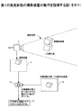
図9に示す例では、被撮影物体の形状が板状であるものとする。また、撮影部11は、図9(a)に示すように、撮影すべき方向に向かって均一な照射光を出力するものとする。さらに、目標撮影状態記憶部21には、目標撮影状態情報として目標明度分布情報が記憶されているものとする。ここで、目標明度分布は、被撮影物体またはそれと同等な物体を目標姿勢にした状態で撮影をすることによって得られた画像の明度分布をいうものとする。この例では、被撮影物体の目標姿勢は、図9(a)において破線で描かれているように、板状の被撮影物体の所定の面に照射光が垂直に当たるような状態であるものとする。そうすると、目標明度分布は、図9(b)において破線で描かれているように、被撮影物体の全体に渡って明度が一定であることを表す情報となる。
【0039】
この例では、図9(a)に示すように、目標姿勢に対して被撮影物体が傾いている。具体的には、撮影部11からA領域までの距離よりも撮影部11からC領域までの距離の方が短くなっている。そして、この状態で被撮影物体が撮影されると、図9(b)に示すように、A領域の明度よりもC領域の明度の方が高くなる。したがって、この撮影により得られた明度分布と目標明度分布とを対比することにより、被撮影物体の姿勢(ここでは、傾き)を検出できる。この後、誘導方向指示出力部23は、図8に示す例と同様に、誘導方向判定部22による検出結果を出力する。具体的には、図9(a)において矢印Dにより表される方向に被撮影物体を回転させる旨の誘導指示が出力される。
【0040】
なお、図9では、説明を簡単にするために、一次元の明度分布に基づいて被撮影物体の傾きを検出しているが、二次元の明度分布に基づいて被撮影物体の傾きを検出するようにしてもよい。
【0041】
図10は、第2の実施形態の撮影装置20の動作を示すフローチャートである。ここで、ステップS11〜S14の処理は、基本的には、図6に示したステップS1〜S4と同じである。ただし、目標撮影状態記憶部21には、被撮影物体の目標姿勢を表す目標姿勢情報が格納されている。そして、ステップS13〜S14において、被撮影物体の姿勢が目標撮影状態の範囲内であるか否かが判定される。
【0042】
被撮影物体の姿勢が目標撮影状態の範囲外であった場合は、ステップS15において、被撮影物体を回転させる方向およびその回転量を算出する。ここで、この回転方向/回転量は、「現在の撮影状態」を「目標撮影状態」に近づけるように算出される。なお、具体例については、図8〜図9を参照しながら説明した通りである。そして、ステップS6において、ユーザに対して、回転方向/回転量を通知するためのメッセージを出力する。これにより、ユーザは、被撮影物体の姿勢を目標姿勢に近づけることができる。この後、ステップS1に戻り、次の画像を撮影する。
【0043】
上記フローチャートの処理は、被撮影物体の姿勢が目標姿勢になるまで繰り返し実行される。そして、被撮影物体の姿勢が目標姿勢になった時点で誘導処理は終了する。
【0044】
なお、上述の第1および第2の実施形態では、被撮影物体の位置または姿勢が検出され、その検出結果に基づいて被撮影物体を誘導するか否かの判定がされているが、他の要因を考慮して誘導処理を行うようにしてもよい。
【0045】
例えば、カメラを用いて物体を撮影し、その撮影画像を解析することにより検出される模様を用いてその物体を識別するシステムを考える。すなわち、識別対象の物体が、撮影画像を解析することにより検出可能な模様を有しているものとする。この場合、図2または図7に示す特徴抽出部17は、撮影部11により得られた画像を解析することにより、被撮影物体が有する模様を検出する。一方、目標撮影状態記憶部13、21には、目標撮影状態情報として、撮影部11により撮影されるべき模様の量の目標値が定義されている。ここで、「模様の量」としては、例えば、その模様が線パターンである場合には、「線の本数」または「各線の長さの総和」などが定義される。
【0046】
誘導方向判定部14または誘導姿勢判定部22は、特徴抽出部17により検出された模様の量と、目標撮影状態情報として定義されている模様の量とを比較する。そして、検出された模様の量の方が少なかった場合には誘導処理を継続し、検出された模様の量の方が多くなった時点で誘導処理を終了するようにしてもよい。
【0047】
図11は、第3の実施形態の撮影装置の構成図である。第3の実施形態の撮影装置30は、撮影部11、撮影画像記憶部12、物体判別部31、物体画像記憶部32、背景画像記憶部33、誘導指示出力部34、撮影画像出力制御部35を備える。なお、撮影部11、撮影画像記憶部12については、第1の実施形態において説明した通りである。
【0048】
物体判別部31は、撮影部11により撮影された画像の中に被撮影物体の画像が含まれているか否かを判定する。そして、撮影部11により撮影された画像の中に被撮影物体の画像が含まれていた場合には、その画像を物体画像として物体画像記憶部32に格納する。一方、被撮影物体の画像が含まれていなかった場合には、その画像を背景画像として背景画像記憶部33に格納する。ただし、被撮影物体の画像が含まれていた場合であっても、不適切な状態で撮影されていた場合には、その画像は廃棄される。なお、物体判別部31は、撮影画像記憶部12に記憶されている画像データを解析してその特徴を抽出する特徴抽出部17を備えている。そして、特徴抽出部17の出力に基づいて、被撮影物体の画像が含まれているか否かを認識できるものとする。
【0049】
誘導指示出力部35は、物体判別部31による判別結果に基づいて、被撮影物体を誘導する指示を作成して出力する。撮影画像出力制御部35は、物体画像記憶部32に記憶されている物体画像と背景画像記憶部32に記憶されている背景画像との差分画像を生成することにより、被撮影物体の画像を切り出す(背景差分処理)。そして、その切り出した被撮影物体の画像を図1に示す識別装置3に送る。なお、識別装置3において背景差分処理が行われる場合には、撮影画像出力制御部35は、物体画像および背景画像の双方を識別装置3に送る。
【0050】
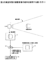
図12および図13は、物体判別部31の動作を説明する図である。図12に示す例では、被撮影物体が撮影部11の撮影視野内に配置されている。したがって、この場合、撮影部11により撮影された画像の中には被撮影物体の画像が含まれている。そして、物体判別部31は、この画像を物体画像として物体画像記憶部32に格納する。この後、物体判別部31は、背景画像記憶部33に背景画像が記憶されているか否かをチェックする。そして、背景画像が記憶されてなければ、誘導指示出力部34は、被撮影物体を撮影部11の撮影視野の外に誘導するための指示を生成する。
【0051】
ユーザは、この誘導指示に従って、図13に示すように、被撮影物体を撮影視野の外に移動させる。そして、その後、撮影部11が撮影を行う。
図13に示す例では、被撮影物体が撮影部11の撮影視野の外に配置されている。したがって、この場合、撮影部11により撮影された画像の中に被撮影物体の画像が含まれていない。そして、物体判別部31は、この画像を背景画像として背景画像記憶部32に格納する。この後、物体判別部31は、物体画像記憶部32に物体画像が記憶されているか否かをチェックする。そして、物体画像が記憶されてなければ、誘導指示出力部34は、被撮影物体を撮影部11の撮影視野内に誘導するための指示を生成する。
【0052】
ユーザは、この誘導指示に従って、図12に示すように、被撮影物体を撮影視野内に移動させる。そして、その後、撮影部11が撮影を行う。
このように、撮影装置30は、物体画像および背景画像の双方を取得するために、必要に応じて、ユーザに対して被撮影物体を誘導する指示を出力する。
【0053】
図14は、物体判別部31による判断手法の一例を説明する図である。なお、被撮影物体は、その全面に特定の色(ここでは、赤色)が付されているものとする。また、物体判別部31は、撮影部11により撮影された画像全体に対する赤色の画像の割合(面積比)を検出する機能を備えているものとする。
【0054】
図14(a)に示す例では、赤色画像が検出されていない。この場合、物体判別部31は、撮影部11により撮影された画像の中に被撮影物体の画像が存在していないものとみなし、その画像を背景画像記憶部33に格納する。
【0055】
図14(b)に示す例では、画像全体に対する赤色画像の割合が8パーセントである。この場合、物体判別部31は、被撮影物体が撮影部11から遠く離れすぎていると判断し、その画像を廃棄する。なお、物体判別部31は、画像全体に対する赤色画像の割合が所定値(例えば、20パーセント)よりも小さかった場合に、被撮影物体が撮影部11から遠く離れすぎていると判断する。
【0056】
図14(c)に示す例では、画像全体に対する赤色画像の割合が30パーセントである。この場合、物体判別部31は、被撮影物体が目標位置に配置されていると判断し、その画像を物体画像記憶部32に格納する。なお、物体判別部31は、画像全体に対する赤色画像の割合が所定範囲内(例えば、20〜40パーセント)に入っていた場合に、被撮影物体が目標位置に配置されているものと判断する。
【0057】
図14(d)に示す例では、画像全体に対する赤色画像の割合が80パーセントである。この場合、物体判別部31は、被撮影物体が撮影部11に近づきすぎていると判断し、その画像を廃棄する。なお、物体判別部31は、画像全体に対する赤色画像の割合が所定値(例えば、40パーセント)よりも大きかった場合に、被撮影物体が撮影部11に近づきすぎていると判断する。
【0058】
図15は、第3の実施形態の撮影装置30の動作を示すフローチャートである。ステップS21では、撮影部11により撮影された画像が撮影画像記憶部12に記憶される。ステップS22では、撮影画像記憶部12に記憶されている画像に対して所定の画像処理(例えば、色成分分析処理など)が抽出される。
【0059】
ステップS23では、画像全体に占める特定の色成分の画像の割合(比率A)を算出する。ステップS24では、比率Aと予め設定されている閾値とを比較する。
【0060】
比率Aが「閾値T3よりも小さい」であれば、撮影された画像の中に被撮影物体の画像が含まれていないものとみなし、ステップS25において、その画像を背景画像記憶部33に格納する。なお、閾値T3は、図14に示す例では、例えば「5パーセント」である。続いて、ステップS26では、物体画像記憶部32に物体画像が格納されているか否かを調べる。そして、物体画像が格納されていない場合は、ステップS27において、被撮影物体を撮影部11の撮影視野内に導くための誘導指示を出力する。一方、物体画像が格納されていた場合は、物体画像および背景画像の双方が取得されていることになるので、処理を終了する。
【0061】
比率Aが「閾値T1よりも大きく、且つ、閾値T2よりも小さい」であれば、撮影された画像の中に被撮影物体の画像が含まれているとみなし、ステップS28において、その画像を物体画像記憶部32に格納する。なお、閾値T1および閾値T2は、図14に示す例では、それぞれ、「20パーセント」および「40パーセント」である。続いて、ステップS29では、背景画像記憶部33に背景画像が格納されているか否かを調べる。そして、背景画像が格納されていない場合は、ステップS30において、被撮影物体を撮影部11の撮影視野の外に誘導するための指示を出力する。一方、背景画像が格納されていた場合は、物体画像および背景画像の双方が取得されていることになるので、処理を終了する。
【0062】
なお、ユーザは、ステップS27またはS30の誘導指示に従って被測定物体を移動させる。そして、その後、ステップS21に戻り、撮影部11が撮影を行う。これにより、物体画像および背景画像の双方が取得される。
【0063】
比率Aが「閾値T3よりも大きく、且つ、閾値T1よりも小さい」或いは「閾値T2よりも大きい」であれば、撮影された画像の中に被撮影物体の画像が含まれてはいるが、被撮影物体が不適切な位置に配置されていると判断される。この場合、ステップS31においてその画像が廃棄される。そして、ステップS32において、被撮影物体を目標位置に誘導するための処理が行われる。すなわち、比率Aが閾値T3よりも大きくかつ閾値T1よりも小さい場合は、被撮影物体を撮影部11に近づけるための誘導指示を出力する。一方、比率Aが閾値T2よりも大きい場合は、被撮影物体を撮影部11から遠ざけるための誘導指示を出力する。そして、その後、ステップS21に戻る。
【0064】
図16は、第4の実施形態の撮影装置の構成図である。第4の実施形態の撮影装置40は、撮影部11、撮影画像記憶部12、距離測定部41、物体判別部42、物体画像記憶部32、背景画像記憶部33、誘導指示出力部34、撮影画像出力制御部35を備える。ここで、撮影部11、撮影画像記憶部12、物体画像記憶部32、背景画像記憶部33、誘導指示出力部34、撮影画像出力制御部35については、第1または第3の実施形態において説明した通りである。
【0065】
距離測定部41は、例えば、公知の距離センサであり、撮影部11と被撮影物体との間の距離を測定する。
物体判別部42は、第3の実施形態の物体判別部31と同様に、撮影部11により撮影された画像の中に被撮影物体の画像が含まれているか否かを判定する。そして、撮影部11により撮影された画像の中に被撮影物体の画像が含まれていた場合には、その画像を物体画像として物体画像記憶部32に格納する。一方、被撮影物体の画像が含まれていなかった場合には、その画像を背景画像として背景画像記憶部33に格納する。ただし、物体判別部42は、距離測定部41の出力の基づいて、撮影された画像の中に被撮影物体の画像が含まれているか否かを判定する。
【0066】
図17は、第4の実施形態の撮影装置40の動作を示すフローチャートである。なお、ステップS21、S25〜S32の処理は、図15を参照しながら説明した通りである。
【0067】
ステップS41では、距離測定部41の出力に基づいて、撮影部11と被撮影物体との間の距離(距離A)を算出する。ステップS42では、距離Aと予め設定されている閾値とを比較する。
【0068】
距離Aが「閾値T3(例えば、16cm)よりも大きい」であれば、撮影された画像の中に被撮影物体の画像が含まれていないものとみなし、ステップS25に進む。また、距離Aが「閾値T1(例えば、4cm)よりも大きく、且つ、閾値T2(例えば、8cm)よりも小さい」であれば、撮影された画像の中に被撮影物体の画像が含まれているとみなし、ステップS28に進む。さらに、距離Aが「閾値T1よりも小さい」あるいは「閾値T2よりも大きく、且つ、閾値T3よりも小さい」であれば、撮影された画像の中に被撮影物体の画像が含まれてはいるが、被撮影物体が不適切な位置に配置されていると判断される。この場合、ステップS31に進む。
【0069】
このように、第4の実施形態の撮影装置40の動作は、基本的に、第3の実施形態の撮影装置30と同じである。ただし、第4の実施形態では、距離センサ等を用いて撮影部11から被撮影物体までの距離を直接的に測定する。このため、上記距離を画像解析のみでは推定できない場合であっても、被撮影物体が写っているか否かを確実に判定することができる。
【0070】
また、第3および第4の実施形態の撮影装置によれば、物体領域と背景領域とを切り分けることができるので、被撮影物体の画像を保持したまま背景画像のみを変更した画像を生成できる。
【0071】
上述した第1〜第4の実施形態では、被撮影物体を適切な位置または姿勢に誘導する機能が提供され、この機能を利用して物体の識別精度の向上が図られている。ところが、仮に背景画像が適切でないとすると、被撮影物体が写っている画像を解析しても、その物体を正確に切り出せないおそれがある。即ち、背景画像が適切でないと、物体の識別精度が低下してしまうおそれがある。このため、物体の識別精度を向上させるためには、予め好適な背景画像を用意しておくことが望ましい。そこで、下記の第5の実施形態の撮影装置は、予め好適な背景画像を取得するための機能を有している。
【0072】
図18は、第5の実施形態の撮影装置の構成図である。第5の実施形態の撮影装置50は、撮影部11、撮影画像記憶部12、目標背景撮影状態記憶部51、背景撮影状態判定部52、撮影装置誘導指示出力部53を備える。なお、撮影部11、撮影画像記憶部12については、第1の実施形態において説明した通りである。
【0073】
目標背景撮影状態記憶部51には、目標背景撮影状態情報として、背景画像として望ましい状態を表す情報が記憶されている。ここで、一般に、背景が明るすぎると、被撮影物体が写っている画像を解析しても、その物体の画像を正確に切り出せないおそれがある。また、背景の明度の分布が均一でない場合も、物体の画像を正確に切り出せないおそれがある。したがって、この場合、目標背景撮影状態情報としては、例えば、背景画像の明度を定義する情報、または、背景画像の明度分布を定義する情報が記憶されるようにしてもよい。或いは、予め用意された適切な背景(目標背景)を撮影することによって得られた画像データであってもよい。
【0074】
背景撮影状態判定部52は、目標背景撮影状態情報を参照し、撮影部11により得られた背景画像(被撮影物体が写っていない画像)が適切であるか否かを判定する。そして、背景画像が適切でないと判断した場合には、撮影部11の位置または姿勢をどのように誘導すべきかを判定する。なお、背景撮影状態判定部52は、撮影画像記憶部12に記憶されている画像データを解析してその特徴を抽出する特徴抽出部17を備え、特徴抽出部17の出力に基づいて背景画像の状態(明度分布など)を認識できるものとする。
【0075】
撮影装置誘導指示出力部53は、背景撮影状態判定部52による判定結果に基づいて、ユーザに対して誘導指示を出力する。これにより、ユーザは、撮影部11を適切な位置に移動させることができる。あるいは、撮影装置誘導指示出力部53は、背景撮影状態判定部52による判定結果に基づいて、撮影部11の位置を移動/回転させるようにしてもよい。
【0076】
次に、図19および図20を参照しながら、第5の実施形態の撮影装置50の動作を説明する。なお、ここでは、撮影部11の撮影視野内に被撮影物体が存在しない状態で撮影が行われ、その画像が撮影画像記憶部12に記憶されているものとする。以下では、この画像を背景画像と呼ぶことにする。
【0077】
図19に示す例では、撮影部11により得られた背景画像の上部領域の明度が高く、下部領域の明度が低い。この場合、背景撮影状態判定部52は、この背景画像の明度分布を分析し、その上部領域の明度が目標背景撮影状態情報として定義されている明度よりも高いことを検出すると、撮影部11を下方へ誘導すべきである(あるいは、撮影部11を下方に向けるべき)と判定する。そして、この判定結果は、誘導指示として撮影装置誘導指示出力部53によりユーザに通知される。
【0078】
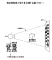
図20に示す例では、撮影部11により得られた背景画像の中に蛍光灯の画像が含まれている。この場合、この背景画像において、蛍光灯に対応する領域(この例では、右端領域)の明度が高くなる。そして、背景撮影状態判定部52は、この背景画像の明度分布を分析し、その右端領域の明度が目標背景撮影状態情報として定義されている明度よりも高いことを検出すると、撮影部11を左方へ誘導すべきである(あるいは、撮影部11を左方向に向けるべき)と判定する。そして、この判定結果は、誘導指示として撮影装置誘導指示出力部53によりユーザに通知される。
【0079】
ユーザは、撮影装置誘導指示出力部53からの誘導指示に従って撮影部11を移動または回転させる。これにより、第5の実施形態の撮影装置は、適切な背景画像を得ることが出来る。すなわち、明度の低い背景画像あるいは明度分布の均一な背景画像得られる。したがって、この背景画像が得られる環境下で識別対象の物体を撮影すれば、その識別精度が向上する。
【0080】
図21は、第5の実施形態の撮影装置50の動作を示すフローチャートである。ステップS51では、撮影部11により背景画像が撮影され、撮影画像記憶部12に記憶される。なお、「背景画像」とは、撮影部11の撮影視野内に被撮影物体が存在しない状態で撮影された画像のことをいう。
【0081】
ステップS52では、撮影画像記憶部12に記憶されている背景画像を解析することにより、画像全体の明度および明度分布を算出する。なお、この処理は、特徴抽出部17により実行される。ステップS53およびS54では、目標背景撮影状態記憶部51に記憶されている明度情報を参照し、ステップS52で算出された背景画像の明度または明度分布が許容範囲内であるか否かを判断する。
【0082】
背景画像の明度または明度分布が許容範囲内でなかった場合は、ステップS55において、より明度の低い背景画像が得られるため、或いは明度分布の均一な背景画像が得られるために、撮影部11をどのように誘導すればよいのかを判定する。そして、ステップS56において、その判定結果が誘導指示として出力される。
【0083】
ユーザは、誘導指示に従って撮影部11を移動または回転させる。そして、ステップS51に戻り、次の背景画像を撮影する。なお、ステップS51〜S56の処理は、撮影部11により得られる背景画像の明度または明度分布が許容範囲内に入るまで繰り返し実行される。
【0084】
なお、第1〜第5の実施形態の撮影装置により提供される機能は、それぞれ任意に組み合わせることができる。すなわち、例えば、第5の実施形態が提供する機能により撮影部11の位置または角度を誘導し、その後、第1〜第4の実施形態が提供する機能により被撮影物体の位置または姿勢を誘導しながら撮影を行うようにしてもよい。また、例えば、第1の実施形態が提供する機能により被撮影物体を適切な位置に誘導した後、第2の実施形態が提供する機能により被撮影物体の姿勢を修正しながら撮影を行うようにしてもよい。
【0085】
次に、誘導指示の出力方法について説明する。なお、以下では、第1の実施形態の撮影装置をベースにして説明をするが、これに限定されるものではなく、第2〜第5の実施形態の撮影装置にも適用可能である。
【0086】
図22に示す撮影装置は、文字列生成部61、表示装置62を備える。そして、文字列生成部61は、誘導方向判定部14により決定された誘導指示に対応する文字列を生成する。また、表示装置62は、文字列生成部61により生成された文字列を表示する。この文字列は、被撮影物体または撮影部11の移動方向、移動量、回転方向、回転角度を指示するガイドメッセージである。ここで、生成された文字列を即座に表示することは容易である。したがって、この方法によれば、ユーザは、被撮影物体または撮影部11の位置や姿勢を素早く修正することができ、物体を識別するための処理時間が短くなる。
【0087】
図23に示す撮影装置は、図形/記号生成部63、表示装置62を備える。そして、図形/記号生成部63は、誘導方向判定部14により決定された誘導指示に対応する図形/記号を生成する。また、表示装置62は、図形/記号生成部61により生成された図形/記号を表示する。この図形/記号は、例えば、被撮影物体または撮影部11の移動方向、移動量、回転方向、回転角度を指示する矢印マークである。したがって、この場合、図22に示す方法により表示されるメッセージを読むことができないユーザ(例えば、外国人)であっても、被撮影物体または撮影部11の位置や姿勢を素早く修正することができる。
【0088】
図24に示す撮影装置は、音声ガイダンス生成部64、スピーカ65を備える。そして、音声ガイダンス生成部64は、誘導方向判定部14により決定された誘導指示に対応する音声ガイダンスを生成し、スピーカ65を介して出力する。ここで、この音声ガイダンスは、被撮影物体または撮影部11の移動方向、移動量、回転方向、回転角度を指示するメッセージである。したがって、この方法によれば、視覚が不自由なユーザであっても、被撮影物体または撮影部11の位置や姿勢を修正することができる。
【0089】
図25に示す撮影装置は、立体音響生成部66、及び複数のスピーカ67a、67bを備える。そして、立体音響生成部66は、誘導方向判定部14により決定された誘導指示に対応するガイド音を生成し、スピーカ67a、67bを介して出力する。ここで、このガイド音は、被撮影物体または撮影部11の移動方向、移動量、回転方向、回転角度を指示する。具体的には、誘導指示は、ガイド音の聞こえてくる方向、ガイド音の音量、ガイド音の音程、ガイド音を周期的に出力する場合にはその周期、などにより表現される。例えば、被撮影物体を撮影部11に近づけさせたい場合には、ガイド音として基準音よりも高い音を出力し、被撮影物体を撮影部11から遠ざけたい場合には、ガイド音として基準音よりも低い音を出力する。このとき、このガイド音の高さは、撮影部11から被撮影物体までの距離に応じて連続的に変化するものとする。
【0090】
図26は、ガイド音を利用して被撮影物体を誘導する方法を説明する図である。この例では、現在、被撮影物体がX点に配置されている。そして、誘導方向判定部14によりこの被撮影物体をY地点に誘導すべき旨の判定がされたものとする。また、ユーザは、スピーカ67aから出力される音Aおよびスピーカ67bから出力される音Bの合成音が聞こえるものとする。この場合、スピーカ67a、67bの音量は、ユーザを基準としたときの合成音の定位方向が、ユーザからY地点へ向かう方向となるように調整される。これにより、ユーザには、Y地点の方角からガイド音が聞こえてくるので、X地点にある被撮影物体をY地点に移動させることができる。
【0091】
図27は、本発明に係わる誘導指示機能(誘導方向判定部14、誘導姿勢判定部22、物体判別部31、42など)を提供するコンピュータのブロック図である。なお、本発明に係わる誘導指示機能は、コンピュータを用いて上述のフローチャートの処理を記述したプログラムを実行することにより実現される。
【0092】
CPU101は、上述のフローチャートに示した処理を記述したプログラムを記憶装置102からメモリ103にロードして実行する。記憶装置102は、例えばハードディスクであり、上記プログラムを格納する。なお、記憶装置102は、コンピュータ100に接続される外部記憶装置であってもよい。メモリ103は、例えば半導体メモリであり、CPU101の作業領域として使用される。ここで、目標撮影状態情報および目標背景撮影状態情報は、例えば、記憶装置102に格納されている。また、撮影画像記憶部12、物体画像記憶部32、背景画像記憶部33は、例えば、メモリ103により実現される。
【0093】
記録媒体ドライバ104は、CPU101の指示に従って可搬性記録媒体105にアクセスする。可搬性記録媒体105は、例えば、半導体デバイス(PCカード等)、磁気的作用により情報が入出力される媒体(フレキシブルディスク、磁気テープ等)、光学的作用により情報が入出力される媒体(光ディスク等)を含むものとする。通信制御装置106は、CPU101の指示に従って、ネットワークを介してデータを送受信する。出力装置107は、例えば、表示装置またはスピーカであり、生成された誘導指示を出力する。
【0094】
図28は、本発明に係わるソフトウェアプログラムの提供方法を説明する図である。本発明に係わるプログラムは、例えば、以下の3つの方法のなかの任意の方法で提供される。
【0095】
(1)コンピュータにインストールされて提供される。この場合、プログラムは、例えば、コンピュータ100の出荷前にそのコンピュータ100にプレインストールされる。
【0096】
(2)可搬性記録媒体に格納されて提供される。この場合、可搬性記録媒体105に格納されるプログラムは、基本的に、記録媒体ドライバ104を介して記憶装置102にインストールされる。
【0097】
(3)ネットワーク上に設けられているプログラムサーバから提供される。この場合、コンピュータ100は、プログラムサーバからダウンロードすることにより対応するプログラムを取得する。ただし、コンピュータ100は、サーバ装置において上記プログラムの実行を依頼し、その実行結果を受け取るようにしてもよい。
【0098】
(付記1) 物体を撮影する撮影手段と、
上記物体の目標撮影状態を表す目標撮影状態情報を記憶する目標撮影状態記憶手段と、
上記目標撮影状態情報および上記撮影手段により撮影された画像に基づいて、上記物体をどのように誘導すべきかを判定する誘導判定手段と、
上記誘導判定手段による判定結果に基づいて上記物体をどのように誘導すべきかを指示する誘導指示出力手段と、
上記撮影手段により撮影された画像を出力する画像出力手段、
を有する撮影装置。
【0099】
(付記2)付記1に記載の撮影装置であって、
上記目標撮影状態情報は、上記物体の目標位置を表す情報を含み、
上記誘導判定手段は、上記物体を誘導すべき方向を判定する。
【0100】
(付記3)付記1に記載の撮影装置であって、
上記目標撮影状態情報は、上記物体の目標姿勢を表す情報を含み、
上記誘導判定手段は、上記物体を誘導すべき回転方向を判定する。
【0101】
(付記4)付記1に記載の撮影装置であって、
上記撮影手段により撮影された画像の中に撮影対象の物体の画像が含まれているか否かを判別する物体判別手段と、
上記物体の画像が含まれている場合の画像を物体画像として記憶する物体画像記憶手段と、
上記物体の画像が含まれていない場合の画像を背景画像として記憶する背景画像記憶手段、をさらに有し、
上記画像出力手段は、上記物体画像および背景画像に基づいて上記物体の画像を切り出し、その切り出した画像を出力する。
【0102】
(付記5)付記1に記載の撮影装置であって、
上記撮影手段により撮影された画像の中に撮影対象の物体の画像が含まれているか否かを判別する物体判別手段と、
上記物体の画像が含まれている場合の画像を物体画像として記憶する物体画像記憶手段と、
上記物体の画像が含まれていない場合の画像を背景画像として記憶する背景画像記憶手段、をさらに有し、
上記画像出力手段は、上記物体画像および背景画像の双方を出力する。
【0103】
(付記6)付記4または5に記載の撮影装置であって、
上記誘導判定手段は、上記物体画像記憶手段に上記物体画像が記憶されていない場合には、上記撮影手段によって上記物体を含む画像が撮影されるようにその物体を誘導し、上記背景画像記憶手段に上記背景画像が記憶されていない場合には、上記撮影手段によって上記物体を含まない画像が撮影されるようにその物体を誘導する。
【0104】
(付記7)付記1に記載の撮影装置であって、
上記撮影手段と上記物体との間の距離を測定する測定手段と、
上記測定手段による測定結果に基づいて、上記撮影手段により撮影された画像の中に撮影対象の物体の画像が含まれているか否かを判別する物体判別手段と、
上記物体の画像が含まれている場合の画像を物体画像として記憶する物体画像記憶手段と、
上記物体の画像が含まれていない場合の画像を背景画像として記憶する背景画像記憶手段、をさらに有し、
上記画像出力手段は、上記物体画像および背景画像に基づいて上記物体の画像を切り出し、その切り出した画像を出力する。
【0105】
(付記8)付記1に記載の撮影装置であって、
上記撮影手段と上記物体との間の距離を測定する測定手段と、
上記測定手段による測定結果に基づいて、上記撮影手段により撮影された画像の中に撮影対象の物体の画像が含まれているか否かを判別する物体判別手段と、
上記物体の画像が含まれている場合の画像を物体画像として記憶する物体画像記憶手段と、
上記物体の画像が含まれていない場合の画像を背景画像として記憶する背景画像記憶手段、をさらに有し、
上記画像出力手段は、上記物体画像および背景画像の双方を出力する。
【0106】
(付記9)付記7または8に記載の撮影装置であって、
上記誘導判定手段は、上記物体画像記憶手段に上記物体画像が記憶されていない場合には、上記撮影手段によって上記物体を含む画像が撮影されるようにその物体を誘導し、上記背景画像記憶手段に上記背景画像が記憶されていない場合には、上記撮影手段によって上記物体を含まない画像が撮影されるようにその物体を誘導する。
【0107】
(付記10)付記1に記載の撮影装置であって、
上記画像出力手段は、上記誘導判定手段が上記物体を誘導する必要がないと判定したときに、上記撮影手段により撮影された画像を出力する。
【0108】
(付記11)付記1に記載の撮影装置であって、
上記物体が所定の模様を有しており、
上記目標撮影状態情報として、上記撮影手段により撮影されるべき模様の量が定義されており、
上記誘導判定手段は、上記撮影手段により撮影された上記物体の画像から検出された上記模様の量が、上記目標撮影状態情報として定義されている模様の量よりも多かったときに、上記物体を誘導する必要がない旨の判定をする。
【0109】
(付記12)特定色の物体を撮影する撮影手段と、
上記撮影手段により撮影された画像全体に対する上記特定色の画像の割合を検出する検出手段と、
上記検出手段による検出結果に基づいて、上記物体を誘導すべき方向を指示する誘導指示出力手段と、
上記撮影手段により撮影された画像を出力する画像出力手段、
を有する撮影装置。
【0110】
(付記13)物体を撮影する撮影手段と、
上記撮影手段と上記物体との間の距離を測定する測定手段と、
上記測定手段による測定結果に基づいて、上記物体を誘導すべき方向を指示する誘導指示出力手段と、
上記撮影手段により撮影された画像を出力する画像出力手段、
を有する撮影装置。
【0111】
(付記14)撮影手段と、
上記撮影手段を用いて背景画像を撮影した場合の目標撮影状態を表す目標撮影状態情報を記憶する目標撮影状態記憶手段と、
上記目標撮影状態情報および上記撮影手段により撮影された画像に基づいて、上記撮影手段を誘導すべき方向または角度を判定する誘導判定手段と、
上記誘導判定手段による判定結果に基づいて上記撮影手段を誘導すべき方向または角度を指示する誘導指示出力手段と、
を有する撮影装置。
【0112】
(付記15)付記14に記載の撮影装置であって、
上記誘導指示出力手段から出力される指示に従って上記撮影手段を移動させる移動手段、
をさらに有する。
【0113】
(付記16)付記1〜11、14、15のいずれか1つに記載の撮影装置であって、
上記誘導指示出力手段は、表示手段を含み、上記誘導判定手段による判定結果に対応する文字列をその表示手段に表示する。
【0114】
(付記17)付記1〜11、14、15のいずれか1つに記載の撮影装置であって、
上記誘導指示出力手段は、表示手段を含み、上記誘導判定手段による判定結果に対応する図形または記号をその表示手段に表示する。
【0115】
(付記18)付記1〜11、14、15のいずれか1つに記載の撮影装置であって、
上記誘導指示出力手段は、上記誘導判定手段による判定結果に対応する音声ガイダンスを出力する。
【0116】
(付記19)付記1〜11、14、15のいずれか1つに記載の撮影装置であって、
上記誘導指示出力手段は、上記誘導判定手段による判定結果に対応する立体音響を生成する。
【0117】
(付記20)撮影装置を用いて撮影される物体を誘導する方法であって、
撮影装置を用いて物体を撮影し、
予め用意されている上記物体の目標撮影状態を表す目標撮影状態情報および上記撮影装置により撮影された画像に基づいて、上記物体をどのように誘導すべきかを判定し、
上記判定結果に基づいて上記物体をどのように誘導すべきかの誘導指示を出力する、
物体誘導方法。
【0118】
(付記21)撮影装置を用いて物体を撮影する方法であって、
撮影装置を用いて物体を撮影する第1の工程と、
予め用意されている上記物体の目標撮影状態を表す目標撮影状態情報および上記撮影装置により撮影された画像に基づいて、上記物体をどのように誘導すべきかを判定する第2の工程と、
上記判定結果に基づいて上記物体をどのように誘導すべきかの誘導指示を出力する第3の工程と、
上記物体を誘導すべき必要がないと判定されるまで上記第1〜第3の工程を繰り返す第4の工程、
を有する撮影方法。
【0119】
【発明の効果】
本発明によれば、被撮影物体を適切な位置および姿勢に誘導することができるので、その物体を識別するための良好な画像が得られる。したがって、物体を識別する精度が向上する。
【0120】
また、適切な背景画像が得られるように撮影装置の位置または角度を誘導するので、被撮影物体の画像を正確に抽出することができ、このことによっても物体を識別する精度が向上する。
【図面の簡単な説明】
【図1】本発明に係わる撮影装置が使用されるシステムの一例の構成図である。
【図2】第1の実施形態の撮影装置の構成図である。
【図3】第1の実施形態の撮影装置の動作を説明する図(その1)である。
【図4】第1の実施形態の撮影装置の動作を説明する図(その2)である。
【図5】第1の実施形態の撮影装置の動作を説明する図(その3)である。
【図6】第1の実施形態の撮影装置の動作を示すフローチャートである。
【図7】第2の実施形態の撮影装置の構成図である。
【図8】第2の実施形態の撮影装置の動作を説明する図(その1)である。
【図9】第2の実施形態の撮影装置の動作を説明する図(その2)である。
【図10】第2の実施形態の撮影装置の動作を示すフローチャートである。
【図11】第3の実施形態の撮影装置の構成図である。
【図12】物体判別部の動作を説明する図(その1)である。
【図13】物体判別部の動作を説明する図(その2)である。
【図14】物体判別部による判断手法の一例を説明する図である。
【図15】第3の実施形態の撮影装置の動作を示すフローチャートである。
【図16】第4の実施形態の撮影装置の構成図である。
【図17】第4の実施形態の撮影装置の動作を示すフローチャートである。
【図18】第5の実施形態の撮影装置の構成図である。
【図19】第5の実施形態の撮影装置の動作を説明する図(その1)である。
【図20】第5の実施形態の撮影装置の動作を説明する図(その2)である。
【図21】第5の実施形態の撮影装置の動作を示すフローチャートである。
【図22】誘導指示を出力する方法を説明する図(その1)である。
【図23】誘導指示を出力する方法を説明する図(その2)である。
【図24】誘導指示を出力する方法を説明する図(その3)である。
【図25】誘導指示を出力する方法を説明する図(その4)である。
【図26】図25に示す方法の具体例を示す図である。
【図27】本発明に係わる誘導指示機能を提供するコンピュータのブロック図である。
【図28】本発明に係わるソフトウェアプログラムの提供方法を説明する図である。
【符号の説明】
10、20、30、40、50 撮影装置
11 撮影部
12 撮影画像記憶部
13、21 目標撮影状態記憶部
14 誘導方向判定部
15 誘導方向指示出力部
16、35 撮影画像出力制御部
22 誘導姿勢判定部
23 誘導姿勢指示出力部
31、42 物体判別部
32 物体画像記憶部
33 背景画像記憶部
34 誘導指示出力部
41 距離測定部
51 目標背景撮影状態記憶部
52 背景撮影状態判定部
53 撮影装置誘導指示出力部[0001]
BACKGROUND OF THE INVENTION
The present invention relates to an imaging apparatus for imaging an object, and more particularly to an imaging apparatus having a function of guiding an object to be imaged to an appropriate position or state.
[0002]
[Prior art]
A technique for photographing an object using a photographing apparatus and identifying the object using an image obtained by the photographing is known. (For example, see
The system described in
[0003]
A technique for guiding an object to a predetermined position based on an image of the object photographed using a camera is also known. (For example, see Patent Document 2.)
However, the system described in Patent Document 2 is provided in a parking lot or the like, and when a vehicle is detected from a captured image, the vehicle is routed to a predetermined route by using a message display, a lamp flashing, or the like. It leads to the destination along. That is, this system does not guide the object to be photographed to a position where the optimum photographing can be performed.
[0004]
[Patent Document 1]
JP 2001-273498 A (see FIGS. 12 to 14 and paragraphs 0070 to 0073)
[Patent Document 2]
Japanese Patent Application Laid-Open No. Sho 64-55574 (2nd page)
[0005]
[Problems to be solved by the invention]
In the method described in
[0006]
In this method, the user can move the object to be photographed to an appropriate position for photographing, but confirms whether or not the object is in a suitable posture for photographing. I can't. Here, the “posture” is a concept including an angle or inclination of the object with respect to the camera.
[0007]
An object of the present invention is to improve the identification accuracy when identifying an object using an image obtained by photographing the object with a photographing apparatus. Further, it is to guide the object to be photographed to an appropriate position or posture.
[0008]
[Means for Solving the Problems]
An image capturing apparatus according to the present invention includes an image capturing unit that captures an object, a target image capturing state storage unit that stores target image capturing state information indicating a target image capturing state of the object, the target image capturing state information, and an image captured by the image capturing unit. Photographed by a guidance determination means for determining how to guide the object based on the above, a guidance instruction output means for instructing how to guide the object based on a determination result by the guidance determination means, and a photographing means Image output means for outputting the processed image.
[0009]
In this photographing apparatus, it is determined how to guide the object by comparing the state of the actually photographed image with the target photographing state. Then, based on the determination result, an instruction is given as to how to guide the object. Therefore, if the object is moved or rotated in accordance with the guidance instruction, the state of the object can be brought close to the target photographing state. As a result, a good image according to the purpose can be obtained.
[0010]
In the photographing apparatus, the target position of the object may be defined as target photographing state information, and the guidance determination unit may determine the direction in which the object should be guided. In this case, since the object is guided to the target position and photographed, a good image can be obtained.
[0011]
In the photographing apparatus, a target posture of the object may be defined as target photographing state information, and the guidance determination unit may determine the rotation direction in which the object is to be guided. In this case, since the object is photographed while being guided to the target posture, a good image can be obtained.
[0012]
The photographing apparatus according to another aspect of the present invention includes a photographing unit, a target photographing state storage unit that stores target photographing state information representing a target photographing state when a background image is photographed using the photographing unit, and the target photographing state information. And a guidance determination unit that determines a direction or angle to guide the imaging unit based on an image captured by the imaging unit, and a direction or angle to guide the imaging unit based on a determination result by the guidance determination unit. Guidance instruction output means for instructing.
[0013]
In this photographing apparatus, since the position or angle of the photographing means is optimized, a good background image can be obtained, and the image of the object to be photographed can be accurately cut out from the photographed image.
[0014]
DETAILED DESCRIPTION OF THE INVENTION
FIG. 1 is a block diagram of an embodiment of a system in which a photographing apparatus according to the present invention is used. In this system, a
[0015]
In order to improve the identification accuracy in this system, when photographing an object, the object needs to be arranged at an appropriate position and in an appropriate posture. Therefore, the photographing apparatus according to the present invention has a function of guiding an object to be photographed to an appropriate position and posture. And the user of this system can move an object according to the said guidance, or can rotate the object. The “object posture” is a concept including an angle or inclination of the object with respect to the camera.
[0016]
FIG. 2 is a configuration diagram of the photographing apparatus according to the first embodiment. The
[0017]
The photographing
[0018]
The target shooting
[0019]
The guiding
[0020]
The guidance direction
[0021]
The captured image
[0022]
Next, the operation of the photographing
[0023]
In the example shown in FIG. 3, the object to be photographed is arranged at a position shifted upward from the target position. In this case, first, a photographed image obtained by the photographing
[0024]
In the example illustrated in FIG. 4, the object to be photographed is too close to the photographing
[0025]
In the example shown in FIG. 5, the object to be photographed is too far from the photographing
[0026]
As described above, when the photographing
[0027]
FIG. 6 is a flowchart illustrating the operation of the
[0028]
In step S1, first, the photographing
[0029]
In steps S3 and S4, the “current shooting state” obtained in step S2 is compared with the “target shooting state” stored in the target shooting
[0030]
In step S5, the direction in which the object to be imaged should be guided is determined. Here, the guide direction is calculated as “a direction in which“ the current shooting state ”approaches the“ target shooting state ”. In addition, about a specific example, it is as having demonstrated referring FIGS. 3-5. In step S6, a message for notifying the user of the guidance direction is output. Thereby, the user can bring the object to be photographed closer to the target position. Thereafter, the process returns to step S1, and the next image is taken.
[0031]
The process of the flowchart is repeatedly executed until the object to be photographed is arranged at the target position. Then, the guidance process ends when the object to be photographed is placed at the target position.
[0032]
FIG. 7 is a configuration diagram of the photographing apparatus according to the second embodiment. The photographing
[0033]
The target shooting
[0034]
The guidance
[0035]
The guidance posture
[0036]
Next, the operation of the photographing
In the example shown in FIG. 8, it is assumed that the shape of the object to be photographed is a cube. The target shooting
[0037]
In this example, the posture of the object to be photographed is tilted to the left. In this case, when the captured image stored in the captured
[0038]
In the example shown in FIG. 9, it is assumed that the object to be photographed has a plate shape. Further, as shown in FIG. 9A, the photographing
[0039]
In this example, as shown in FIG. 9A, the object to be photographed is tilted with respect to the target posture. Specifically, the distance from the photographing
[0040]
In FIG. 9, for the sake of simplicity, the tilt of the object to be photographed is detected based on the one-dimensional brightness distribution, but the tilt of the object to be photographed is detected based on the two-dimensional brightness distribution. You may do it.
[0041]
FIG. 10 is a flowchart illustrating the operation of the
[0042]
If the posture of the object to be photographed is outside the range of the target photographing state, the direction and amount of rotation of the object to be photographed are calculated in step S15. Here, the rotation direction / rotation amount is calculated so that the “current shooting state” approaches the “target shooting state”. Specific examples are as described with reference to FIGS. 8 to 9. In step S6, a message for notifying the user of the rotation direction / rotation amount is output. As a result, the user can bring the posture of the object to be photographed closer to the target posture. Thereafter, the process returns to step S1, and the next image is taken.
[0043]
The processing of the flowchart is repeatedly executed until the posture of the object to be photographed reaches the target posture. Then, the guidance process ends when the posture of the object to be photographed becomes the target posture.
[0044]
In the first and second embodiments described above, the position or orientation of the object to be photographed is detected, and it is determined whether to guide the object to be photographed based on the detection result. You may make it perform a guidance process in consideration of a factor.
[0045]
For example, consider a system in which an object is photographed using a camera and the object is identified using a pattern detected by analyzing the photographed image. That is, it is assumed that the object to be identified has a pattern that can be detected by analyzing the captured image. In this case, the
[0046]
The guidance
[0047]
FIG. 11 is a configuration diagram of a photographing apparatus according to the third embodiment. The
[0048]
The
[0049]
The guidance
[0050]
12 and 13 are diagrams for explaining the operation of the
[0051]
The user moves the object to be photographed out of the field of view as shown in FIG. 13 in accordance with this guidance instruction. Thereafter, the photographing
In the example illustrated in FIG. 13, the object to be photographed is disposed outside the photographing field of view of the photographing
[0052]
In accordance with this guidance instruction, the user moves the object to be photographed within the photographing field of view as shown in FIG. Thereafter, the photographing
As described above, the
[0053]
FIG. 14 is a diagram illustrating an example of a determination method performed by the
[0054]
In the example shown in FIG. 14A, no red image is detected. In this case, the
[0055]
In the example shown in FIG. 14B, the ratio of the red image to the entire image is 8%. In this case, the
[0056]
In the example shown in FIG. 14C, the ratio of the red image to the entire image is 30%. In this case, the
[0057]
In the example shown in FIG. 14D, the ratio of the red image to the entire image is 80%. In this case, the
[0058]
FIG. 15 is a flowchart illustrating the operation of the
[0059]
In step S23, the ratio (ratio A) of the image of a specific color component in the entire image is calculated. In step S24, the ratio A is compared with a preset threshold value.
[0060]
If the ratio A is “smaller than the threshold value T3”, it is regarded that the image of the object to be photographed is not included in the photographed image, and the image is stored in the background
[0061]
If the ratio A is “greater than the threshold value T1 and smaller than the threshold value T2,” it is considered that the image of the object to be photographed is included in the photographed image, and the image is converted to an object in step S28. Stored in the
[0062]
The user moves the object to be measured according to the guidance instruction in step S27 or S30. Thereafter, the process returns to step S21, and the photographing
[0063]
If the ratio A is “larger than the threshold value T3 and smaller than the threshold value T1” or “greater than the threshold value T2,” the image of the object to be photographed is included in the photographed image. It is determined that the object to be photographed is placed at an inappropriate position. In this case, the image is discarded in step S31. In step S32, a process for guiding the object to be photographed to the target position is performed. That is, when the ratio A is larger than the threshold value T3 and smaller than the threshold value T1, a guidance instruction for bringing the object to be photographed closer to the photographing
[0064]
FIG. 16 is a configuration diagram of a photographing apparatus according to the fourth embodiment. The
[0065]
The
Similar to the
[0066]
FIG. 17 is a flowchart illustrating the operation of the
[0067]
In step S41, a distance (distance A) between the photographing
[0068]
If the distance A is “greater than the threshold value T3 (for example, 16 cm)”, it is considered that the image of the object to be photographed is not included in the photographed image, and the process proceeds to step S25. If the distance A is “larger than the threshold T1 (for example, 4 cm) and smaller than the threshold T2 (for example, 8 cm)”, the image of the object to be captured is included in the captured image. The process proceeds to step S28. Further, if the distance A is “smaller than the threshold value T1” or “larger than the threshold value T2 and smaller than the threshold value T3”, the image of the object to be photographed is included in the photographed image. However, it is determined that the object to be photographed is disposed at an inappropriate position. In this case, the process proceeds to step S31.
[0069]
As described above, the operation of the
[0070]
Further, according to the imaging devices of the third and fourth embodiments, the object region and the background region can be separated, so that an image in which only the background image is changed while the image of the object to be imaged is retained can be generated.
[0071]
In the above-described first to fourth embodiments, a function for guiding the object to be photographed to an appropriate position or posture is provided, and the identification accuracy of the object is improved using this function. However, if the background image is not appropriate, there is a possibility that the object cannot be accurately cut out even if the image showing the object to be photographed is analyzed. That is, if the background image is not appropriate, the object identification accuracy may be reduced. For this reason, in order to improve the object identification accuracy, it is desirable to prepare a suitable background image in advance. Therefore, the imaging apparatus of the fifth embodiment described below has a function for acquiring a suitable background image in advance.
[0072]
FIG. 18 is a configuration diagram of a photographing apparatus according to the fifth embodiment. An
[0073]
The target background shooting
[0074]
The background shooting
[0075]
The imaging device guidance
[0076]
Next, the operation of the photographing
[0077]
In the example shown in FIG. 19, the brightness of the upper region of the background image obtained by the photographing
[0078]
In the example illustrated in FIG. 20, the background image obtained by the
[0079]
The user moves or rotates the
[0080]
FIG. 21 is a flowchart illustrating the operation of the
[0081]
In step S52, the brightness and brightness distribution of the entire image are calculated by analyzing the background image stored in the captured
[0082]
If the lightness or lightness distribution of the background image is not within the allowable range, in step S55, a background image with a lower lightness is obtained or a background image with a uniform lightness distribution is obtained. Determine how to guide. In step S56, the determination result is output as a guidance instruction.
[0083]
The user moves or rotates the
[0084]
Note that the functions provided by the imaging apparatuses of the first to fifth embodiments can be arbitrarily combined. That is, for example, the position or angle of the photographing
[0085]
Next, a method for outputting a guidance instruction will be described. In the following, the description will be given based on the imaging apparatus of the first embodiment, but the present invention is not limited to this, and the imaging apparatus of the second to fifth embodiments can also be applied.
[0086]
The imaging apparatus shown in FIG. 22 includes a character
[0087]
The imaging apparatus shown in FIG. 23 includes a graphic /
[0088]
24 includes a voice
[0089]
The imaging apparatus illustrated in FIG. 25 includes a stereophonic
[0090]
FIG. 26 is a diagram illustrating a method for guiding an object to be photographed using a guide sound. In this example, the object to be photographed is currently arranged at the point X. It is assumed that the guidance
[0091]
FIG. 27 is a block diagram of a computer that provides a guidance instruction function (guidance
[0092]
The
[0093]
The
[0094]
FIG. 28 is a diagram for explaining a software program providing method according to the present invention. The program according to the present invention is provided, for example, by any one of the following three methods.
[0095]
(1) Provided by being installed in a computer. In this case, for example, the program is preinstalled in the
[0096]
(2) Provided by being stored in a portable recording medium. In this case, the program stored in the
[0097]
(3) Provided from a program server provided on the network. In this case, the
[0098]
(Appendix 1) photographing means for photographing an object;
Target shooting state storage means for storing target shooting state information representing the target shooting state of the object;
Guidance determining means for determining how to guide the object based on the target photographing state information and the image photographed by the photographing means;
Guidance instruction output means for instructing how to guide the object based on the determination result by the guidance determination means;
Image output means for outputting an image photographed by the photographing means;
A photographing apparatus having
[0099]
(Supplementary note 2) The photographing apparatus according to
The target shooting state information includes information indicating the target position of the object,
The guidance determination unit determines a direction in which the object should be guided.
[0100]
(Supplementary Note 3) The imaging apparatus according to
The target shooting state information includes information indicating a target posture of the object,
The guidance determination means determines a rotation direction in which the object is to be guided.
[0101]
(Supplementary note 4) The photographing apparatus according to
Object discriminating means for discriminating whether or not an image of an object to be photographed is included in the image photographed by the photographing means;
Object image storage means for storing an image when the image of the object is included as an object image;
A background image storage means for storing an image when the image of the object is not included as a background image;
The image output means cuts out an image of the object based on the object image and the background image, and outputs the cut out image.
[0102]
(Additional remark 5) It is an imaging device of
Object discriminating means for discriminating whether or not an image of an object to be photographed is included in the image photographed by the photographing means;
Object image storage means for storing an image when the image of the object is included as an object image;
A background image storage means for storing an image when the image of the object is not included as a background image;
The image output means outputs both the object image and the background image.
[0103]
(Appendix 6) The photographing apparatus according to
When the object image is not stored in the object image storage unit, the guidance determination unit guides the object so that an image including the object is captured by the imaging unit, and the background image storage unit If the background image is not stored, the object is guided so that an image not including the object is photographed by the photographing means.
[0104]
(Appendix 7) The photographing apparatus according to
Measuring means for measuring the distance between the photographing means and the object;
An object discriminating unit that discriminates whether or not an image of an object to be photographed is included in an image photographed by the photographing unit based on a measurement result by the measuring unit;
Object image storage means for storing an image when the image of the object is included as an object image;
A background image storage means for storing an image when the image of the object is not included as a background image;
The image output means cuts out an image of the object based on the object image and the background image, and outputs the cut out image.
[0105]
(Appendix 8) The imaging apparatus according to
Measuring means for measuring the distance between the photographing means and the object;
An object discriminating unit that discriminates whether or not an image of an object to be photographed is included in an image photographed by the photographing unit based on a measurement result by the measuring unit;
Object image storage means for storing an image when the image of the object is included as an object image;
A background image storage means for storing an image when the image of the object is not included as a background image;
The image output means outputs both the object image and the background image.
[0106]
(Supplementary note 9) The photographing apparatus according to
When the object image is not stored in the object image storage unit, the guidance determination unit guides the object so that an image including the object is captured by the imaging unit, and the background image storage unit If the background image is not stored, the object is guided so that an image not including the object is photographed by the photographing means.
[0107]
(Supplementary note 10) The imaging apparatus according to
The image output means outputs an image photographed by the photographing means when the guidance judging means judges that it is not necessary to guide the object.
[0108]
(Supplementary note 11) The photographing apparatus according to
The object has a predetermined pattern,
As the target shooting state information, the amount of pattern to be shot by the shooting means is defined,
The guidance determination means determines the object when the amount of the pattern detected from the image of the object photographed by the photographing means is larger than the amount of the pattern defined as the target photographing state information. Judge that there is no need to guide.
[0109]
(Supplementary Note 12) Imaging means for imaging an object of a specific color;
Detecting means for detecting a ratio of the image of the specific color with respect to the entire image photographed by the photographing means;
A guidance instruction output means for instructing a direction in which the object should be guided based on a detection result by the detection means;
Image output means for outputting an image photographed by the photographing means;
A photographing apparatus having
[0110]
(Supplementary note 13) An imaging means for imaging an object;
Measuring means for measuring the distance between the photographing means and the object;
Guidance instruction output means for instructing the direction in which the object should be guided based on the measurement result by the measurement means;
Image output means for outputting an image photographed by the photographing means;
A photographing apparatus having
[0111]
(Appendix 14) Photography means;
A target shooting state storage unit that stores target shooting state information representing a target shooting state when a background image is shot using the shooting unit;
Guidance determination means for determining a direction or angle to guide the photographing means based on the target photographing state information and an image photographed by the photographing means;
Guidance instruction output means for instructing the direction or angle to guide the imaging means based on the determination result by the guidance determination means;
A photographing apparatus having
[0112]
(Supplementary note 15) The photographing apparatus according to
Moving means for moving the photographing means in accordance with an instruction output from the guidance instruction output means;
It has further.
[0113]
(Supplementary note 16) The photographing apparatus according to any one of
The guidance instruction output means includes display means, and displays a character string corresponding to the determination result by the guidance determination means on the display means.
[0114]
(Supplementary note 17) The imaging apparatus according to any one of
The guidance instruction output means includes display means, and displays a graphic or symbol corresponding to the determination result by the guidance determination means on the display means.
[0115]
(Supplementary note 18) The photographing apparatus according to any one of
The guidance instruction output means outputs voice guidance corresponding to the determination result by the guidance determination means.
[0116]
(Supplementary note 19) The imaging apparatus according to any one of
The said guidance instruction | indication output means produces | generates the stereophonic sound corresponding to the determination result by the said guidance determination means.
[0117]
(Supplementary note 20) A method for guiding an object to be photographed using a photographing apparatus,
Shoot an object using a shooting device,
Based on the target shooting state information representing the target shooting state of the object prepared in advance and the image shot by the shooting device, it is determined how to guide the object,
Based on the determination result, a guidance instruction on how to guide the object is output.
Object guidance method.
[0118]
(Supplementary note 21) A method of photographing an object using a photographing device,
A first step of photographing an object using a photographing device;
A second step of determining how to guide the object based on target photographing state information representing a target photographing state of the object prepared in advance and an image photographed by the photographing device;
A third step of outputting a guidance instruction on how to guide the object based on the determination result;
A fourth step of repeating the first to third steps until it is determined that the object should not be guided;
A photographing method comprising:
[0119]
【The invention's effect】
According to the present invention, since an object to be photographed can be guided to an appropriate position and posture, a good image for identifying the object can be obtained. Therefore, the accuracy for identifying the object is improved.
[0120]
Further, since the position or angle of the photographing apparatus is guided so that an appropriate background image can be obtained, the image of the object to be photographed can be accurately extracted, and this also improves the accuracy of identifying the object.
[Brief description of the drawings]
FIG. 1 is a configuration diagram of an example of a system in which a photographing apparatus according to the present invention is used.
FIG. 2 is a configuration diagram of a photographing apparatus according to the first embodiment.
FIG. 3 is a diagram (part 1) for explaining the operation of the photographing apparatus according to the first embodiment;
FIG. 4 is a diagram (part 2) for explaining the operation of the photographing apparatus of the first embodiment;
FIG. 5 is a diagram (part 3) for explaining the operation of the photographing apparatus of the first embodiment;
FIG. 6 is a flowchart illustrating an operation of the photographing apparatus according to the first embodiment.
FIG. 7 is a configuration diagram of a photographing apparatus according to a second embodiment.
FIG. 8 is a diagram (part 1) for explaining the operation of the photographing apparatus according to the second embodiment;
FIG. 9 is a diagram (part 2) for explaining the operation of the photographing apparatus of the second embodiment.
FIG. 10 is a flowchart illustrating an operation of the photographing apparatus according to the second embodiment.
FIG. 11 is a configuration diagram of a photographing apparatus according to a third embodiment.
FIG. 12 is a diagram (part 1) illustrating an operation of an object determination unit.
FIG. 13 is a diagram (part 2) for explaining the operation of the object discriminating unit;
FIG. 14 is a diagram illustrating an example of a determination method performed by an object determination unit.
FIG. 15 is a flowchart illustrating an operation of the imaging apparatus according to the third embodiment.
FIG. 16 is a configuration diagram of a photographing apparatus according to a fourth embodiment.
FIG. 17 is a flowchart showing the operation of the photographing apparatus of the fourth embodiment.
FIG. 18 is a configuration diagram of a photographing apparatus according to a fifth embodiment.
FIG. 19 is a diagram (part 1) for explaining the operation of the photographing apparatus of the fifth embodiment.
FIG. 20 is a diagram (part 2) for explaining the operation of the photographing apparatus of the fifth embodiment.
FIG. 21 is a flowchart showing the operation of the photographing apparatus of the fifth embodiment.
FIG. 22 is a diagram (part 1) illustrating a method for outputting a guidance instruction;
FIG. 23 is a second diagram illustrating a method for outputting a guidance instruction;
FIG. 24 is a third diagram illustrating a method for outputting a guidance instruction;
FIG. 25 is a diagram (No. 4) illustrating a method for outputting a guidance instruction;
26 is a diagram showing a specific example of the method shown in FIG. 25. FIG.
FIG. 27 is a block diagram of a computer that provides a guidance instruction function according to the present invention.
FIG. 28 is a diagram for explaining a software program providing method according to the present invention.
[Explanation of symbols]
10, 20, 30, 40, 50
11 Shooting Department
12 Captured image storage
13, 21 Target shooting state storage unit
14 Guide direction determination unit
15 Guide direction indication output section
16, 35 Captured image output control unit
22 Guide posture determination unit
23 Guidance posture instruction output unit
31, 42 Object discrimination unit
32 Object image storage unit
33 Background Image Storage Unit
34 Guidance instruction output unit
41 Distance measurement unit
51 Target background shooting state storage unit
52 Background shooting state determination unit
53 Imaging device guidance instruction output unit
Claims (3)
上記撮影手段を用いて背景画像を撮影した場合の目標撮影状態を表す目標撮影状態情報を記憶する目標撮影状態記憶手段と、
上記目標撮影状態情報および上記撮影手段により撮影された画像に基づいて、上記撮影手段を誘導すべき方向または角度を判定する誘導判定手段と、
上記誘導判定手段による判定結果に基づいて上記撮影手段を誘導すべき方向または角度を指示する誘導指示出力手段と、
を有する撮影装置。Photographing means;
A target shooting state storage unit that stores target shooting state information representing a target shooting state when a background image is shot using the shooting unit;
Guidance determination means for determining a direction or angle to guide the photographing means based on the target photographing state information and an image photographed by the photographing means;
Guidance instruction output means for instructing the direction or angle to guide the imaging means based on the determination result by the guidance determination means;
A photographing apparatus having
上記誘導指示出力手段は、表示手段を含み、上記誘導判定手段による判定結果に対応する文字列をその表示手段に表示する。The imaging device according to claim 1 ,
The guidance instruction output means includes display means, and displays a character string corresponding to the determination result by the guidance determination means on the display means.
上記誘導指示出力手段は、上記誘導判定手段による判定結果に対応する立体音響を生成する。The imaging device according to claim 1 ,
The said guidance instruction | indication output means produces | generates the stereophonic sound corresponding to the determination result by the said guidance determination means.
Priority Applications (2)
| Application Number | Priority Date | Filing Date | Title |
|---|---|---|---|
| JP2003083928A JP3860552B2 (en) | 2003-03-25 | 2003-03-25 | Imaging device |
| US10/784,776 US8395673B2 (en) | 2003-03-25 | 2004-02-24 | Shooting device and method with function for guiding an object to be shot |
Applications Claiming Priority (1)
| Application Number | Priority Date | Filing Date | Title |
|---|---|---|---|
| JP2003083928A JP3860552B2 (en) | 2003-03-25 | 2003-03-25 | Imaging device |
Related Child Applications (3)
| Application Number | Title | Priority Date | Filing Date |
|---|---|---|---|
| JP2006102346A Division JP4481951B2 (en) | 2006-04-03 | 2006-04-03 | Imaging device |
| JP2006102345A Division JP4286844B2 (en) | 2006-04-03 | 2006-04-03 | Imaging device |
| JP2006207309A Division JP2007020197A (en) | 2006-07-31 | 2006-07-31 | Photographing apparatus |
Publications (2)
| Publication Number | Publication Date |
|---|---|
| JP2004297223A JP2004297223A (en) | 2004-10-21 |
| JP3860552B2 true JP3860552B2 (en) | 2006-12-20 |
Family
ID=32985064
Family Applications (1)
| Application Number | Title | Priority Date | Filing Date |
|---|---|---|---|
| JP2003083928A Expired - Fee Related JP3860552B2 (en) | 2003-03-25 | 2003-03-25 | Imaging device |
Country Status (2)
| Country | Link |
|---|---|
| US (1) | US8395673B2 (en) |
| JP (1) | JP3860552B2 (en) |
Families Citing this family (28)
| Publication number | Priority date | Publication date | Assignee | Title |
|---|---|---|---|---|
| JP4515850B2 (en) | 2004-07-30 | 2010-08-04 | 富士通株式会社 | Biometric device guidance screen control method, biometric device and program thereof |
| EP2031556A4 (en) * | 2006-06-08 | 2013-01-02 | Fujitsu Ltd | Guidance device and method |
| US7991285B2 (en) * | 2008-01-08 | 2011-08-02 | Sony Ericsson Mobile Communications Ab | Using a captured background image for taking a photograph |
| KR101030652B1 (en) * | 2008-12-16 | 2011-04-20 | 아이리텍 잉크 | An Acquisition System and Method of High Quality Eye Images for Iris Recognition |
| KR20100091286A (en) * | 2009-02-10 | 2010-08-19 | 삼성전자주식회사 | A support method of visual presenter function and a portable device using the same, and supporting device of the portable device |
| US8803992B2 (en) * | 2010-05-12 | 2014-08-12 | Fuji Xerox Co., Ltd. | Augmented reality navigation for repeat photography and difference extraction |
| JP5800600B2 (en) * | 2011-06-24 | 2015-10-28 | オリンパス株式会社 | Imaging apparatus, imaging method, and program |
| JP2013115444A (en) * | 2011-11-24 | 2013-06-10 | Sanyo Electric Co Ltd | Electronic camera |
| US8687104B2 (en) * | 2012-03-27 | 2014-04-01 | Amazon Technologies, Inc. | User-guided object identification |
| US9374517B2 (en) | 2012-10-12 | 2016-06-21 | Ebay Inc. | Guided photography and video on a mobile device |
| US9552598B2 (en) | 2012-10-12 | 2017-01-24 | Ebay Inc. | Mobile trigger web workflow |
| US9554049B2 (en) * | 2012-12-04 | 2017-01-24 | Ebay Inc. | Guided video capture for item listings |
| JP6160148B2 (en) | 2013-03-19 | 2017-07-12 | 富士通株式会社 | Biological information input device, biometric information input program, and biometric information input method |
| KR20140121694A (en) * | 2013-04-08 | 2014-10-16 | 삼성전자주식회사 | Image photographing apparatus and method for controlling the same |
| EP3152737A4 (en) | 2014-06-03 | 2018-01-24 | Jones, Freddy | In-time registration of temporally separated image acquisition |
| JP6274097B2 (en) * | 2014-12-17 | 2018-02-07 | カシオ計算機株式会社 | Product identification device and product recognition navigation method |
| JP6836306B2 (en) * | 2017-02-01 | 2021-02-24 | キヤノン株式会社 | Imaging control device, its control method, program and recording medium |
| US20190021652A1 (en) * | 2017-07-19 | 2019-01-24 | International Business Machines Corporation | Monitoring the posture of a user |
| CN108429782B (en) * | 2017-09-12 | 2020-11-06 | 腾讯科技(深圳)有限公司 | Information pushing method and device, terminal and server |
| JP6547856B2 (en) * | 2018-01-09 | 2019-07-24 | カシオ計算機株式会社 | Information display device, guidance display method and program |
| CN111630837B (en) * | 2018-01-25 | 2022-08-09 | 索尼半导体解决方案公司 | Image processing apparatus, output information control method, and program |
| US10574881B2 (en) * | 2018-02-15 | 2020-02-25 | Adobe Inc. | Smart guide to capture digital images that align with a target image model |
| JP6668519B1 (en) * | 2019-02-04 | 2020-03-18 | ソフトバンク株式会社 | Remote control function setting program, remote control server, remote control function setting method, mobile terminal |
| JP7355531B2 (en) * | 2019-06-24 | 2023-10-03 | ニデックプレシジョン株式会社 | Imaging device and imaging guidance method |
| CN113132618B (en) * | 2019-12-31 | 2022-09-09 | 华为技术有限公司 | Auxiliary photographing method and device, terminal equipment and storage medium |
| WO2021237590A1 (en) * | 2020-05-28 | 2021-12-02 | 北京小米移动软件有限公司南京分公司 | Image collection method and apparatus, and device and storage medium |
| US11496674B2 (en) * | 2020-09-18 | 2022-11-08 | Microsoft Technology Licensing, Llc | Camera placement guidance |
| CN113038015B (en) * | 2021-03-19 | 2023-03-24 | 城云科技(中国)有限公司 | Secondary shooting method and system |
Family Cites Families (23)
| Publication number | Priority date | Publication date | Assignee | Title |
|---|---|---|---|---|
| JPS6015780A (en) | 1983-07-08 | 1985-01-26 | Hitachi Ltd | Robot |
| JPS6455674A (en) | 1987-08-26 | 1989-03-02 | Matsushita Electric Works Ltd | Guide system |
| JPH05268599A (en) | 1992-03-17 | 1993-10-15 | Fujitsu Ltd | Automatic control system for portrait pickup camera in television conference system |
| JPH06268902A (en) | 1993-03-12 | 1994-09-22 | Matsushita Electric Ind Co Ltd | Picture recognition device |
| US5742141A (en) * | 1996-06-04 | 1998-04-21 | Ford Motor Company | Semi-autonomous parking control system for a vehicle providing tactile feedback to a vehicle operator |
| JP3587635B2 (en) * | 1996-11-15 | 2004-11-10 | 沖電気工業株式会社 | Personal recognition device using iris and automatic transaction system using this personal recognition device |
| JPH11196320A (en) | 1997-12-26 | 1999-07-21 | Canon Inc | Moving image processor, its method and computer readable storage medium |
| EP0908846A3 (en) * | 1997-10-07 | 2000-03-29 | Canon Kabushiki Kaisha | Moving object detection apparatus and method |
| US6906744B1 (en) * | 1999-09-28 | 2005-06-14 | Nikon Corporation | Electronic camera |
| JP2001174881A (en) | 1999-12-16 | 2001-06-29 | Casio Comput Co Ltd | Photographing device and storage medium |
| JP2001229485A (en) * | 2000-02-14 | 2001-08-24 | Biichi Rock:Kk | Method for arranging acoustic traffic signal adding device for visually handicapped person guidance |
| JP4521086B2 (en) * | 2000-03-13 | 2010-08-11 | 株式会社東芝 | Face image recognition apparatus and face image recognition method |
| JP3825222B2 (en) | 2000-03-24 | 2006-09-27 | 松下電器産業株式会社 | Personal authentication device, personal authentication system, and electronic payment system |
| JP2001314648A (en) * | 2000-05-10 | 2001-11-13 | Namco Ltd | Game apparatus and information storage medium |
| EP1167120B1 (en) * | 2000-06-30 | 2014-08-27 | Panasonic Corporation | Rendering device for parking aid |
| JP2002036991A (en) * | 2000-07-27 | 2002-02-06 | Honda Motor Co Ltd | Parking support device |
| JP3647030B2 (en) | 2000-08-31 | 2005-05-11 | 株式会社日立国際電気 | Object detection method, object detection apparatus, and object detection program |
| US6281806B1 (en) * | 2000-10-12 | 2001-08-28 | Ford Global Technologies, Inc. | Driver road hazard warning and illumination system |
| US7271839B2 (en) * | 2001-03-15 | 2007-09-18 | Lg Electronics Inc. | Display device of focal angle and focal distance in iris recognition system |
| JP2002330318A (en) | 2001-04-27 | 2002-11-15 | Matsushita Electric Ind Co Ltd | Mobile terminal |
| JP3700614B2 (en) * | 2001-06-22 | 2005-09-28 | 株式会社豊田自動織機 | Parking assistance device |
| TWI278782B (en) * | 2001-08-24 | 2007-04-11 | Toshiba Corp | Personal recognition apparatus |
| JP4033672B2 (en) * | 2001-12-26 | 2008-01-16 | 株式会社日立製作所 | Emergency notification system |
-
2003
- 2003-03-25 JP JP2003083928A patent/JP3860552B2/en not_active Expired - Fee Related
-
2004
- 2004-02-24 US US10/784,776 patent/US8395673B2/en not_active Expired - Fee Related
Also Published As
| Publication number | Publication date |
|---|---|
| US20040189829A1 (en) | 2004-09-30 |
| US8395673B2 (en) | 2013-03-12 |
| JP2004297223A (en) | 2004-10-21 |
Similar Documents
| Publication | Publication Date | Title |
|---|---|---|
| JP3860552B2 (en) | Imaging device | |
| US8176426B2 (en) | Image reproduction apparatus and image reproduction program product | |
| EP2052347B1 (en) | Real-time face tracking in a digital image acquisition device | |
| US8068639B2 (en) | Image pickup apparatus, control method therefor, and computer program for detecting image blur according to movement speed and change in size of face area | |
| JP6614335B2 (en) | Image display system, terminal, method and program | |
| US20170162195A1 (en) | Information processing apparatus, information processing method, and recording medium | |
| CN103916592A (en) | Apparatus and method for photographing portrait in portable terminal having camera | |
| JP4764959B1 (en) | Imaging apparatus and control method thereof | |
| KR20140061033A (en) | Method and apparatus for recognizing text image and photography method using the same | |
| KR20120010875A (en) | Apparatus and Method for Providing Recognition Guide for Augmented Reality Object | |
| JP2007241402A (en) | Pretense decision device in face authentication and face authentication device using it | |
| JP6494418B2 (en) | Image analysis apparatus, image analysis method, and program | |
| KR102186597B1 (en) | Target size measurement system and method | |
| US11508174B2 (en) | Image processing method and image processing device | |
| US20210093227A1 (en) | Image processing system and control method thereof | |
| US20090190838A1 (en) | Training a User on an Accessiblity Device | |
| CN113092079A (en) | Definition detection target plate and method and system, electronic equipment and detection platform | |
| JP4286844B2 (en) | Imaging device | |
| JP2008217714A (en) | Tracking device, tracking method and tracking program | |
| JP4481951B2 (en) | Imaging device | |
| US20220076399A1 (en) | Photographing guide device | |
| JP2007020197A (en) | Photographing apparatus | |
| WO2017057694A1 (en) | Musical score image analysis device | |
| JP4058454B1 (en) | Camera shooting support system | |
| JP2006270137A (en) | Imaging apparatus |
Legal Events
| Date | Code | Title | Description |
|---|---|---|---|
| A521 | Request for written amendment filed |
Free format text: JAPANESE INTERMEDIATE CODE: A821 Effective date: 20041104 |
|
| RD01 | Notification of change of attorney |
Free format text: JAPANESE INTERMEDIATE CODE: A7426 Effective date: 20041104 |
|
| A521 | Request for written amendment filed |
Free format text: JAPANESE INTERMEDIATE CODE: A821 Effective date: 20050407 |
|
| RD02 | Notification of acceptance of power of attorney |
Free format text: JAPANESE INTERMEDIATE CODE: A7422 Effective date: 20050407 |
|
| A711 | Notification of change in applicant |
Free format text: JAPANESE INTERMEDIATE CODE: A711 Effective date: 20050331 |
|
| A131 | Notification of reasons for refusal |
Free format text: JAPANESE INTERMEDIATE CODE: A131 Effective date: 20060131 |
|
| A521 | Request for written amendment filed |
Free format text: JAPANESE INTERMEDIATE CODE: A523 Effective date: 20060403 |
|
| A02 | Decision of refusal |
Free format text: JAPANESE INTERMEDIATE CODE: A02 Effective date: 20060620 |
|
| A521 | Request for written amendment filed |
Free format text: JAPANESE INTERMEDIATE CODE: A523 Effective date: 20060731 |
|
| A911 | Transfer to examiner for re-examination before appeal (zenchi) |
Free format text: JAPANESE INTERMEDIATE CODE: A911 Effective date: 20060904 |
|
| TRDD | Decision of grant or rejection written | ||
| A01 | Written decision to grant a patent or to grant a registration (utility model) |
Free format text: JAPANESE INTERMEDIATE CODE: A01 Effective date: 20060919 |
|
| A61 | First payment of annual fees (during grant procedure) |
Free format text: JAPANESE INTERMEDIATE CODE: A61 Effective date: 20060921 |
|
| R150 | Certificate of patent or registration of utility model |
Ref document number: 3860552 Country of ref document: JP Free format text: JAPANESE INTERMEDIATE CODE: R150 Free format text: JAPANESE INTERMEDIATE CODE: R150 |
|
| FPAY | Renewal fee payment (event date is renewal date of database) |
Free format text: PAYMENT UNTIL: 20090929 Year of fee payment: 3 |
|
| FPAY | Renewal fee payment (event date is renewal date of database) |
Free format text: PAYMENT UNTIL: 20100929 Year of fee payment: 4 |
|
| FPAY | Renewal fee payment (event date is renewal date of database) |
Free format text: PAYMENT UNTIL: 20100929 Year of fee payment: 4 |
|
| FPAY | Renewal fee payment (event date is renewal date of database) |
Free format text: PAYMENT UNTIL: 20110929 Year of fee payment: 5 |
|
| FPAY | Renewal fee payment (event date is renewal date of database) |
Free format text: PAYMENT UNTIL: 20120929 Year of fee payment: 6 |
|
| FPAY | Renewal fee payment (event date is renewal date of database) |
Free format text: PAYMENT UNTIL: 20120929 Year of fee payment: 6 |
|
| FPAY | Renewal fee payment (event date is renewal date of database) |
Free format text: PAYMENT UNTIL: 20130929 Year of fee payment: 7 |
|
| S111 | Request for change of ownership or part of ownership |
Free format text: JAPANESE INTERMEDIATE CODE: R313117 |
|
| R350 | Written notification of registration of transfer |
Free format text: JAPANESE INTERMEDIATE CODE: R350 |
|
| LAPS | Cancellation because of no payment of annual fees |