JP3857477B2 - Optical transmission system - Google Patents
Optical transmission system Download PDFInfo
- Publication number
- JP3857477B2 JP3857477B2 JP31889499A JP31889499A JP3857477B2 JP 3857477 B2 JP3857477 B2 JP 3857477B2 JP 31889499 A JP31889499 A JP 31889499A JP 31889499 A JP31889499 A JP 31889499A JP 3857477 B2 JP3857477 B2 JP 3857477B2
- Authority
- JP
- Japan
- Prior art keywords
- optical
- polarization
- wavelength
- optical transmission
- mode dispersion
- Prior art date
- Legal status (The legal status is an assumption and is not a legal conclusion. Google has not performed a legal analysis and makes no representation as to the accuracy of the status listed.)
- Expired - Fee Related
Links
Images


Classifications
-
- H—ELECTRICITY
- H04—ELECTRIC COMMUNICATION TECHNIQUE
- H04B—TRANSMISSION
- H04B10/00—Transmission systems employing electromagnetic waves other than radio-waves, e.g. infrared, visible or ultraviolet light, or employing corpuscular radiation, e.g. quantum communication
- H04B10/25—Arrangements specific to fibre transmission
- H04B10/2507—Arrangements specific to fibre transmission for the reduction or elimination of distortion or dispersion
- H04B10/2569—Arrangements specific to fibre transmission for the reduction or elimination of distortion or dispersion due to polarisation mode dispersion [PMD]
Landscapes
- Physics & Mathematics (AREA)
- Electromagnetism (AREA)
- Engineering & Computer Science (AREA)
- Computer Networks & Wireless Communication (AREA)
- Signal Processing (AREA)
- Optical Communication System (AREA)
Abstract
Description
【0001】
【発明の属する技術分野】
この発明は、超高速超長距離光伝送を行う際に伝送信号の品質を劣化させる偏波モード分散特性を補償する機能を有した光伝送システムに関する。
【0002】
【従来の技術】
異なる屈折率をもつ物質中を光が進むとき、この屈折率の大小によって、物質中における光の伝搬速度が異なる。また、入射光の偏波方向が異なる場合、屈折率の異なる材料(異方性材料)中における光の伝搬は、材料中における偏波の状態に応じ、材料通過後の遅延時間が異なるという現象を生じさせる。ここで、材料中における各固有偏波方向に偏光した光に生じる遅延時間差を偏波モード分散(以下、「PMD」(Polarization Mode Dispersion)という。)と呼ぶ。
【0003】
一般に、光伝送路で用いられるシングルモードファイバは、その長手方向に沿って局所的にわずかな異方性が生じている。したがって、このような異方性を有するファイバ中を光が伝搬すると、光信号は、この異方性が生じている箇所において、光信号が有する偏波方向に依存した遅延差が生じる。この偏波の違いによる遅延差が光伝送路内で蓄積されると、受信端における信号波形の劣化を引き起こすことになる。
【0004】
図14は、パルス幅がパルス間隔に等しいNRZ(Non-Return to Zero)信号の光伝送における1dBペナルティを引き起こす光伝送路のPMDの大きさと光伝送速度(ビットレート)との関係を示す図である。この図14に示す関係は、文献「偏波モード分散による光システムのフェージング(Fading in Lightwave Systems Due to Polarization-Mode Dispersion)」(C.D.Poole,R.W.Tkach,A.R.Chraplyvy,and D.A.Fishman著、IEEE Photonics Technology Letters,Vol.3,No.1,January 1991,pp.68-70)に記載された関係式をもとに作成したものである。
【0005】
すなわち、上記文献には、パワーペナルティが1dB劣化する時のPMDの大きさΔτと、NRZ信号のパルス幅T(=1/B:「B」はビットレートである)との関係を、次式(1)として示している。すなわち、
Δτ/T≒0.4 ・・・(1)
としている。この式(1)をもとに、パワーペナルティが1dB劣化する時のPMDの大きさΔτと、NRZ信号のビットレートBとの関係を求めると、図14に示す結果となる。この結果、たとえば、40Gbit/sのNRZ信号を光伝送する場合、光伝送路のもつPMDを10ps以下に抑えなければならないことがわかる。
【0006】
一方、現実の光伝送路は、低PMDのファイバであっても平均0.1ps/√(km)程度のPMDを有する。このことは、10000km伝送後に10ps程度のPMDが生じることを示す。さらに、光伝送路内におけるPMDは、その大きさが時間的に変動するという特性をもつ。したがって、光ファイバを敷設した後、PMDの時間的な変動に応じたPMD補償を行う必要がある。
【0007】
このPMD補償を行うためには、たとえば図15に示したPMD補償回路が用いられる。図15において、送信器10から送信された光信号は光伝送路11を伝搬する間に、PMDによる波形歪を受け、受信器14に入力される直前の光伝送路11上の光信号から、光タップ24を用いて一部の光信号を取り出し、PMD検出器23によってPMDを検出する。PMD検出器23によって検出されたPMDの値は、制御回路22に入力され、制御回路22は、入力されたPMDの値に対する補償量を決定し、PMD補償光回路21に出力する。PMD補償光回路21は、光伝送路11上の光信号のPMDを補償し、下流の光伝送路11上に出力する。この結果、受信器14は、PMDが補償された光信号を受信することになる。
【0008】
なお、特開平7−231297号公報には、光伝送路内に挿入されてPMDを補償する偏波モード分散補償装置が記載されている。この偏波モード分散補償装置では、PMDを受けた光信号を等化光回路を介して受信し、一度符号列を識別して、識別前後の信号を比較することで、その差信号を得て、整流、積分することで等化誤差信号を生成し、等化光回路のパラメータを少し変化させて等化誤差信号が減少する方向を見つけ、制御ループによってパラメータ制御を繰り返すことで、自動的に等化誤差信号が最小となる状態に追い込み、これによって光信号のPMDによる信号品質劣化が最小となるようにしている。
【0009】
【発明が解決しようとする課題】
ところで、光伝送路11上における各偏波モード間の結合が小さく、また光伝送路11上における非線形光学効果の影響が小さい状態であれば、図15に示したように、受信器14の直前におけるPMDの一括補償を行うことができるが、偏波モード間の結合が大きく、また非線形光学効果の影響が無視できない状態である場合では、光伝送路11上においてPMDによる偏波モード間の遅延差が一度でも生じると、それぞれの偏波モードが受ける非線形光学効果の大きさが異なり、さらに偏波モード間におけるパワーの結合が生じることから、各偏波モードの光信号波形は互いに異なったものとなり、受信器14の直前において一括したPMD補償を行っても、もはや光信号波形の再現を行うことが困難になるという問題点があった。
【0010】
また、光信号が光波長多重信号である場合には、波長多重数に応じた数のPMD補償回路を設ける必要があるため、このPMD補償回路の小型化が要望されていた。
【0011】
この発明は上記に鑑みてなされたもので、確実にPMD補償を行って光信号波形の再現を行うことができ、かつPMD補償のための構成を小型化することができる光伝送システムを得ることを目的とする。
【0016】
【課題を解決するための手段】
上記目的を達成するため、この発明にかかる光伝送システムは、光送信器と光受信器との間の光伝送路上に1以上の光増幅中継器を有した光伝送システムにおいて、1以上の中継スパン毎、または、偏波モード間の結合度合いに応じた偏波モード分散補償が可能な光伝送路距離範囲毎、に偏波モード分散補償を行う補償手段を備え、前記補償手段は、入力された光波長多重信号を各波長毎もしくは各チャネル毎に分波する波長分波器と、前記波長分波器によって分波された光信号に対する偏波モード分散補償を行う偏波モード分散補償手段と、前記偏波モード分散補償手段によって補償された各波長毎もしくは各チャネル毎の光信号を合波して出力する波長合波器と、を備えたことを特徴とする。
【0017】
この発明によれば、波長分波器が、入力された光波長多重信号を各波長毎もしくは各チャネル毎に分波し、偏波モード分散補償手段が、前記波長分波器によって分波された光信号に対する偏波モード分散補償を行い、波長合波器が、前記偏波モード分散補償手段によって補償された各波長毎もしくは各チャネル毎の光信号を合波して出力し、光波長多重信号の偏波モード分散補償を行う。
【0018】
つぎの発明にかかる光伝送システムは、光送信器と光受信器との間の光伝送路上に1以上の光増幅中継器を有した光伝送システムにおいて、1以上の中継スパン毎、または、偏波モード間の結合度合いに応じた偏波モード分散補償が可能な光伝送路距離範囲毎、に偏波モード分散補償を行う補償手段を備え、前記補償手段は、入力された光波長多重信号を所定波長もしくは所定チャネル毎のブロック単位に分波する波長分波器と、前記波長分波器によって分波された各ブロック単位の光信号に対する偏波モード分散補償を行う偏波モード分散補償手段と、前記偏波モード分散補償手段によって補償された各ブロック毎の光信号を合波して出力する波長合波器と、を備えたことを特徴とする。
【0019】
この発明によれば、波長分波器が、入力された光波長多重信号を所定波長もしくは所定チャネル毎のブロック単位に分波し、偏波モード分散補償手段が、前記波長分波器によって分波された各ブロック単位の光信号に対する偏波モード分散補償を行い、波長合波器が、前記偏波モード分散補償手段によって補償された各ブロック毎の光信号を合波して出力し、光波長多重信号の偏波モード分散補償を行う。
【0020】
つぎの発明にかかる光伝送システムは、光送信器と光受信器との間の光伝送路上に1以上の光増幅中継器を有した光伝送システムにおいて、1以上の中継スパン毎、または、偏波モード間の結合度合いに応じた偏波モード分散補償が可能な光伝送路距離範囲毎、に偏波モード分散補償を行う補償手段を備え、前記補償手段は、入力された光波長多重信号を各波長毎もしくは各チャネル毎に分波する波長分波器と、前記波長分波器によって分波された各波長毎もしくは各チャネル毎の光信号を所定ブロック毎に合波する第1の波長合波器と、前記第1の波長合波器によって合波された光信号に対する偏波モード分散補償を行う偏波モード分散補償手段と、前記偏波モード分散補償手段によって補償された各ブロック毎の光信号を合波して出力する第2の波長合波器と、を備えたことを特徴とする。
【0021】
この発明によれば、波長分波器が、入力された光波長多重信号を各波長毎もしくは各チャネル毎に分波し、第1の波長合波器が、前記波長分波器によって分波された各波長毎もしくは各チャネル毎の光信号を所定ブロック毎に合波し、偏波モード分散補償手段が、前記第1の波長合波器によって合波された光信号に対する偏波モード分散補償を行い、第2の波長合波器が、前記偏波モード分散補償手段によって補償された各ブロック毎の光信号を合波して出力し、光波長多重信号の偏波モード分散補償を行う。この場合、第1の波長合波器は、波長分波器によって分波された各波長毎もしくは各チャネル毎の光信号のうちの任意の組合せをもった波長あるいはチャネルをまとめてブロック化して合波することができ、たとえば、隣接しない波長あるいはチャネルどうしをブロック化することができる。
【0022】
つぎの発明にかかる光伝送システムは、上記の発明において、前記第1の波長合波器は、前記波長分波器によって分波された各波長毎もしくは各チャネル毎の光信号のうち同一偏波方向をもつ光信号を所定ブロック毎に合波することを特徴とする。
【0023】
この発明によれば、第1の波長合波器が、波長分波器によって分波された各波長毎もしくは各チャネル毎の光信号のうち同一偏波方向をもつ光信号を所定ブロック毎に合波し、この所定ブロック単位で偏波モード分散補償を行うようにしている。
【0024】
つぎの発明にかかる光伝送システムは、光送信器と光受信器との間の光伝送路上に1以上の光増幅中継器を有した光伝送システムにおいて、1以上の中継スパン毎、または、偏波モード間の結合度合いに応じた偏波モード分散補償が可能な光伝送路距離範囲毎、に偏波モード分散補償を行う補償手段を備え、前記補償手段は、入力された光波長多重信号を各波長毎もしくは各チャネル毎に分波する波長分波器と、前記波長分波器によって分波された各波長毎もしくは各チャネル毎の光信号のうち互いに直交する偏光光をもつ光信号を所定ブロック毎に合波する偏波合成手段と、前記偏波合成手段によって合波された光信号に対する偏波モード分散補償を行う偏波モード分散補償手段と、前記偏波モード分散補償手段によって補償された各ブロック毎の光信号を合波して出力する第2の波長合波器と、を備えたことを特徴とする。
【0025】
この発明によれば、波長分波器が、入力された光波長多重信号を各波長毎もしくは各チャネル毎に分波し、偏波合成手段が、前記波長分波器によって分波された各波長毎もしくは各チャネル毎の光信号のうち互いに直交する偏光をもつ光信号を所定ブロック毎に合波し、偏波モード分散補償手段が、前記偏波合成手段によって合波された光信号に対する偏波モード分散補償を行い、第2の波長合波器が、前記偏波モード分散補償手段によって補償された各ブロック毎の光信号を合波して出力し、光波長多重信号の偏波モード分散補償を行う。この場合、偏波合成手段は、直交する偏光方向をもった波長あるいはチャネル構成をもった光波長多重信号が入力される場合、直交する偏光方向をもった波長あるいはチャネルどうしにブロック化し、それぞれ偏波合成を行う。
【0026】
つぎの発明にかかる光伝送システムは、上記の発明において、前記光伝送路の終端または終端近傍に前記補償手段をさらに設けたことを特徴とする。
【0027】
この発明によれば、補償手段を光伝送路の終端または終端近傍、すなわち、光受信器の直前に設け、最終的に残った偏波モード分散を補償する。
【0028】
つぎの発明にかかる光伝送システムは、上記の発明において、前記光伝送路の送信端または送信端近傍に、前記光伝送路の終端における光信号の品質劣化が最小となる偏波面をもつ光信号が入力されるように調整する偏波調整手段をさらに設けたことを特徴とする。
【0029】
この発明によれば、偏波調整手段が、前記光伝送路の送信端または送信端近傍に設けられ、光伝送路の終端における光信号の品質劣化が最小となる偏波面をもつ光信号が入力されるように調整するようにしている。
【0030】
つぎの発明にかかる光伝送システムは、上記の発明において、前記補償手段内を構成する波長分波器、第1の波長合波器、第2の波長合波器、波長合波器、偏波モード分散補償手段との間を偏波面保持光ファイバで接続したことを特徴とする。
【0031】
この発明によれば、補償手段内を構成する波長分波器、第1の波長合波器、第2の波長合波器、波長合波器、偏波モード分散補償手段との間を偏波面保持光ファイバで接続し、補償手段内の各光学部品間の偏波を保持するようにしている。
【0032】
つぎの発明にかかる光伝送システムは、上記の発明において、各前記補償手段または各前記偏波モード分散補償手段は、偏波モード分散量に対応する光遅延差を補正する光学系を備え、前記光受信器は、当該光受信器における偏波モード分散量を検出する検出手段と、前記検出手段によって検出された偏波モード分散量を用いて各前記光学系を制御する複数の制御手段と、を備えたことを特徴とする。
【0033】
この発明によれば、光受信器が、検出手段によって当該光受信器における偏波モード分散量を検出し、複数の制御手段が、前記検出手段によって検出された偏波モード分散量を用い、各補償手段または各偏波モード分散補償手段の光学系による前記偏波モード分散量に対応する光遅延差を補正するようにし、光伝送路上に配置される各補償手段または各偏波モード分散補償手段の構成を小型化かつ簡易にする。
【0034】
つぎの発明にかかる光伝送システムは、上記の発明において、後段の光増幅中継器における光増幅用励起レーザの偏光方向に対応する最適な偏光方向をもつ光信号に調整して前記後段の光増幅中継器に偏波合成出力する光増幅用偏波調整手段をさらに備え、前記光増幅用偏波調整手段から入力される最適な偏光方向をもった光信号によって少なくとも前記後段の光増幅中継器の光増幅を最適動作させることを特徴とする。
【0035】
この発明によれば、光増幅用偏波調整手段が、後段の光増幅中継器における光増幅用励起レーザの偏光方向に対応する最適な偏光方向、たとえば後段の光増幅器に用いられる励起用光レーザの偏光方向に直交する偏波方向をもつ光信号に調整して前記後段の光増幅中継器に偏波合成出力し、該光増幅用偏波調整手段から入力される最適な偏光方向をもった光信号によって少なくとも後段の光増幅中継器の光増幅を最適動作させるとともに、後段の光伝送路においてPMDの影響が小さくできるような偏光方向に選択調整可能なようにしている。
【0036】
つぎの発明にかかる光伝送システムは、上記の発明において、前記光増幅用偏波調整手段は、前記補償手段の後段に接続したことを特徴とする。
【0037】
この発明によれば、光増幅用偏波調整手段が、補償手段の後段に接続され、PMD補償された光信号を偏波面調整することによって直ちに最適な偏光方向をもった光信号に調整して出力するようにしている。
【0038】
つぎの発明にかかる光伝送システムは、上記の発明において、前記光伝送路上に、少なくとも前記光受信器に入力される光信号の品質劣化が最小となる偏波面をもつ光信号が入力されるように該入力される光信号の偏波面を調整する最小PMD設定用偏波調整手段をさらに設けたことを特徴とする。
【0039】
この発明によれば、最小PMD設定用偏波調整手段が光伝送路上に設けられ、少なくとも光受信器に入力される光信号の品質劣化が最小となる偏波面をもつ光信号が入力されるように該入力される光信号の偏波面を調整するようにしている。
【0040】
つぎの発明にかかる光伝送システムは、上記の発明において、前記補償手段は、光増幅中継器内に組み込まれたことを特徴とする。
【0041】
この発明によれば、補償手段を光増幅中継器内、特に光増幅器内に組み込むようにし、補償手段および光増幅中継器のそれぞれに要求される耐圧性能、耐水性能等の耐環境構成をひとつの構成としてまとめるようにしている。
【0042】
つぎの発明にかかる光伝送システムは、上記の発明において、前記補償手段は、前記光受信器内に組み込まれたことを特徴とする。
【0043】
この発明によれば、補償手段を光受信器内、特に光増幅器内に組み込むようにし、光受信器に入力された光信号のPMDを補償し、この光信号のPMDによる光信号の品質劣化を最終的に抑えるようにしている。
【0044】
【発明の実施の形態】
以下に添付図面を参照して、この発明にかかる光伝送システムの好適な実施の形態を詳細に説明する。
【0045】
実施の形態1.
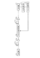
まず、この発明の実施の形態1について説明する。図1は、この発明の実施の形態1である光伝送システムの全体構成を示す図である。図1において、この光伝送システムは、光信号を送信する送信器10と、この光信号を受信する受信器14とを有する。送信器10と受信器14との間は、光ファイバによる光伝送路11(11a〜11f)によって接続され、光伝送路11上には、複数の光中継増幅器12a〜12eと複数のPMD補償回路13a〜13eとが設けられる。複数の光中継増幅器12a〜12eは、入力された光信号を増幅し、複数のPMD補償回路13a〜13eは、光信号中のPMDを補償する。光中継増幅器12a〜12eとの間の各距離は、中継スパンであり、図1に示した複数のPMD補償回路13a〜13eは、各中継スパン内にそれぞれ一つ設けられている。
【0046】
図2は、PMD補償回路13aの構成を示すブロック図である。図2において、PMD補償回路13aの光タップ24は、光伝送路11b上の光信号の一部を取り出し、PMD検出器23は、光タップ24によって取り出した光信号をもとにPMDによる波形劣化を検出し、PMD波形歪に対する補償量を制御回路22に送出する。制御回路22は、入力された補償量をもとに、光伝送路11aから入力される光信号のPMD波形歪を補償させる指示情報をPMD補償光回路21に出力する。PMD補償光回路21は、この指示情報をもとにPMD波形歪の補償を行う。このPMD波形歪の補償が行われた光信号は、光伝送路11b上に送出され、光タップ24による光信号の一部取り出しによるフィードバック制御が実行される。なお、その他のPMD補償回路13b〜13eは、PMD補償回路13aと同一構成である。
【0047】
さらに、図3は、PMD補償回路13aの詳細構成を示す図である。図3において、偏波調整部26、偏光ビームスプリッタ27a,27bおよび遅延光学系27cは、図2に示したPMD補償光回路21に相当する。また、制御回路22a,22bは、制御回路22に相当する。図3において、偏波調整部26は、光伝送路11から入力される、PMD歪みを受けた光信号の偏光状態を最適にする。すなわち、偏波調整部26は、光信号の各固有偏波モード成分のうち、PMDによる時間遅延が生じた偏波モード成分が偏光ビームスプリッタ27aによって遅延光学系27cに分離されるように偏波面を回転調整し、偏光ビームスプリッタ27aに出力する。
【0048】
偏光ビームスプリッタ27aは、PMDによる時間遅延を補償するため、各固有偏波モード成分である、偏光l1と偏光l2の光信号に分波する。たとえば、光伝送路で受けたPMDによって、相対的に偏光l1の光信号が、偏光l2の光信号に比べてΔτだけの時間遅延が生じているものとする。偏光l1の光信号成分は、遅延光学系27cに出力され、偏光l2の光信号成分は、そのまま偏光ビームスプリッタ27bに出力される。遅延光学系27cは、制御回路22aの制御のもとに、入力された偏光l1の信号光を、PMDによって生じた、偏光l1と偏光l2の光信号間の遅延差Δτだけ遅延して、偏光ビームスプリッタ27bに出力する。
【0049】
この遅延差Δτは、主として、遅延光学系27c内のミラーm1,m2の距離を調整し、偏光l1の光信号の往復時間を変えることによって設定される。このミラーm1,m2間の距離は、制御回路22aによって行われる。PMD検出器23は、光タップ24を介して取り出した光信号の一部をもとにPMDによる波形劣化を検出し、PMD波形歪に対する補償量を算出し、この補償量を制御回路22a,22bに送出する。制御回路22aは、入力された補償量に相当する遅延差Δτを求め、この遅延差Δτに相当するミラーm1,m2間の距離を算出し、この算出した距離となるようにミラーm2を移動させる。一方、制御回路22bは、PMD波形歪みが最小になるように、偏波調整部26に対して、偏波面調整を行わせ、偏光ビームスプリッタ27aによる二つの固有偏波モードである偏光l1の信号光と偏光l2の光信号との分波を確実に行わせる。
【0050】
ここで、図4を参照して、PMD補償処理について説明する。図4(a)は、PMD補償前における偏波光と直交偏波光との関係を示し、図4(b)は、PMD補償後における偏波光と直交偏波光との関係を示している。図4において、偏波調整部26による偏光ビームスプリッタ27aに対する偏波調整が正しく行われている場合、偏光l2の光信号は、偏光l1の光信号に対する直交偏波成分として表せる。偏光l2の光信号は、偏光l1の光信号に対して、PMD歪みによる遅延差Δτ分遅延して伝送される。遅延光学系27cは、偏光l1の光信号を遅延差Δτ分遅延させるので、図4(b)に示すように、偏光l1の光信号と偏光l2の光信号との遅延差Δτは解消され、PMD歪みは補償されることになる。
【0051】
その後、偏光ビームスプリッタ27bは、偏光ビームスプリッタ27aから直接入力された偏光l2の光信号と、遅延光学系27cから入力された偏光l1の光信号とを合波し、PMD補償がなされた光信号として光伝送路11上に出力する。その後、さらに、この光信号の一部が光タップ24によって取り出され、フィードバックループによるPMD補償が実行される。
【0052】
光伝送路11上の各中継スパン毎に生ずるPMDは、一般に、偏波モード間の結合が小さく、また非線形光学効果の影響を無視できる程度のもの、すなわち線形補償ができるものであることを前提に、この実施の形態1では、線形のPMD補償回路13を各中継スパン毎に設けている。この結果、PMD補償回路13は、光信号が、PMD補償処理を行うことができない程のPMDを受ける前に、確実にPMD補償を行うようにしているので、受信器14は、送信器10によって送信された光信号波形を確実に再現することができる。
【0053】
したがって、一つの中継スパンの距離による光信号のPMDが、PMD補償回路13によって補償することができないものである場合には、PMD補償回路13がPMD補償できる距離毎に、このPMD補償回路13を設置するようにすればよい。
【0054】
また、この実施の形態1では、PMD補償回路13を光伝送路11上にそれぞれ独立させて設けるようにしているが、各PMD補償回路13をそれぞれ光増幅中継器12内に設けるようにしてもよい。このような構成とすることによって、たとえば光伝送路11上の各部を可能な限り一纏めにした構成ができ、PMD補償回路13および光増幅中継器12のそれぞれに要求される耐圧性能、耐水性能等の耐環境構成を簡易な構成とすることができる。
【0055】
また、上述した実施の形態1では、光伝送路11上にPMD補償回路13を設けているが、受信器14内の図示しない光増幅器内にPMD補償回路を設け、光信号のPMDを補償するようにしてもよい。
【0056】
この実施の形態1によれば、偏波モード間のパワー結合が小さく、また非線形光学効果の影響を無視できる程度のPMDが生成される光伝送路の距離毎に、PMD補償回路13を設け、PMDが拡大する前に線形のPMD補償を行うようにしているので、光伝送路11上で発生したPMDによる光信号の波形劣化を確実に抑圧することができ、受信器14は光信号波形の再現を確実に行うことができる。
【0057】
実施の形態2.
つぎに、この発明の実施の形態2について説明する。実施の形態1では、偏波モード間のパワー結合が小さく、また非線形光学効果の影響を無視できる程度のPMDが生成される各中継スパン毎にPMD補償回路13を設けるようにしていたが、この実施の形態2では、さらに受信器14の直前あるいは受信器14の近傍の光伝送路11上にPMD補償回路13を設けるようにしている。
【0058】
図5は、この実施の形態2における光伝送システムの全体構成を示す図である。図5において、この光伝送システムでは、受信器14の直前の光伝送路11上に実施の形態1に示したPMD補償回路13と同じ構成のPMD補償回路13fを設けている。その他の構成は、実施の形態1と同じ構成であり、同一構成部分には同一符号を付している。
【0059】
送信器10から光伝送路11を介してPMD補償回路13fに至るまでに、光信号のPMDは、PMD補償回路13(13a〜13e)によってPMD補償されるが、PMD補償回路13fは、さらに、このPMD補償された光信号に残るPMDを最終段階としてPMD補償し、このPMD補償された光信号を受信器14に出力する。
【0060】
この実施の形態2によれば、光信号のPMD補償を受信器14の直前あるいは近傍で行うようにしているので、受信器14は光信号波形の再現を一層確実に行うことができる。特に、光伝送路11上のPMDは時間的に変動するため、各PMD補償回路13a〜13eがPMDの時間的変動に追随することができない可能性もあり、このような場合に補償することができなかったPMDを確実に補償することができる。
【0061】
実施の形態3.
つぎに、この発明の実施の形態3について説明する。この実施の形態3では、上述した実施の形態2の構成に対し、さらに光伝送路11の送信器10端あるいは近傍に、受信器14端における光信号のPMDによる影響が最小となるように光信号の偏波面を調整する偏波調整部を設けるようにしている。
【0062】
図6は、この実施の形態3における光伝送システムの全体構成を示す図である。図6において、この光伝送システムでは、光伝送路11の送信器10端に偏波調整部26を設けるようにしている。偏波調整部26は、受信器14端における光信号のPMDあるいは受信器14自体が検出するPMD歪み量が最小となる偏波面に調整し、この調整した光信号を光伝送路11上に送信するようにしている。その他の構成は、実施の形態2と同じ構成であり、同一構成部分には同一符号を付している。
【0063】
偏波調整部26による偏波面の調整は、この光伝送システムの光伝送路を敷設した時に予めPMDの影響が最小となる偏波面を決定する。偏波調整部26は、この決定された偏波面をもつ光信号を光伝送路11上に送信する。なお、PMDの時間的変動が大きい場合には、他の通信手段あるいは他の光伝送路を用いて、常時あるいは定期的に偏波面調整を行うようにしてもよい。
【0064】
この実施の形態3によれば、光伝送路11の送信器10端に偏波調整部26を設けて、受信器14におけるPMDの影響が最小となる偏波面をもった光信号を送信するようにしているので、光伝送路11上において発生するPMDによる波形歪みを最小限に抑えることができ、受信器14は光信号波形の再現を一層確実に行うことができる。
【0065】
実施の形態4.
つぎに、この発明の実施の形態4について説明する。上述した実施の形態1〜3では、光信号が多重化されていない信号であることを前提として説明したが、この実施の形態4では、光伝送システムの光信号が波長多重化された光波長多重信号である場合においても実施の形態1〜3に示したPMD補償を行えるようにしている。
【0066】
図7は、この実施の形態4である光伝送システムのPMD補償回路の構成を示す図である。このPMD補償回路30は、実施の形態1〜3におけるPMD補償回路13のそれぞれに代えて配置され、その他の構成は、実施の形態1〜3に示した構成と同じである。
【0067】
図7において、光伝送路11aには、光波長多重数が「n」である光波長多重信号が伝送され、この光波長多重信号はPMD補償回路30に入力される。PMD補償回路30は、分波器31と、光波長多重数に対応したPMD補償回路33−1〜33−nと、合波器32とを有する。分波器31は、光波長多重された各波長λ1 〜λn あるいはこれに対応する各チャネル毎に分波する。各PMD補償回路33−1〜33−nは、実施の形態1〜3で示したPMD補償回路13と同じ構成であり、分波器31によって分波された各波長毎にPMD補償を行い、PMD補償された光信号を合波器32に出力する。合波器32は、PMD補償回路33−1〜33−nから出力されたn本の光信号を合波し、光伝送路11b上に出力する。
【0068】
この実施の形態4によれば、光波長多重信号であっても各チャネルに対応した各波長毎にPMD補償を行うようにしているので、実施の形態1〜3と同様に、光波長多重信号である光信号のPMD補償を確実に行い、受信器14における光波長多重毎の光信号波形の再現を確実に行うことができる。
【0069】
実施の形態5.
つぎに、この発明の実施の形態5について説明する。上述した実施の形態4では、光波長多重化された各波長λ1 〜λn 毎にPMD補償を行うようにしていたが、この実施の形態5では、所定ブロック単位の波長毎にまとめ、このまとめたブロック単位でPMD補償を行うようにしている。
【0070】
図8は、この実施の形態5である光伝送システムのPMD補償回路の構成を示す図である。このPMD補償回路40は、実施の形態1〜3におけるPMD補償回路13のそれぞれに代えて配置され、その他の構成は、実施の形態1〜3に示した構成と同じである。
【0071】
図8において、光伝送路11aには、光波長多重数が「n」である光波長多重信号が伝送され、この光波長多重信号はPMD補償回路40に入力される。PMD補償回路40は、分波器41と、PMD補償回路43−1〜43−lと、合波器42とを有する。分波器41は、光波長多重された各波長λ1 〜λn あるいは各チャネルを複数の波長あるいは複数のチャネルにまとめたブロック毎に、光波長多重信号を分波する。ブロック数「l」に対応したPMD補償回路43−1〜43−lは、各ブロックの光信号に対するPMD補償を行う。たとえば、PMD補償回路43−1は、分波器41によって分波され、波長λ1 〜λa を有した一つの光信号に対するPMD補償を行う。このPMD補償回路43−1〜43−lの構成は、実施の形態1〜3に示したPMD補償回路13と同じ構成である。合波器42は、各PMD補償回路43−1〜43−lによってPMD補償された各光信号を合波し、光伝送路11b上に出力する。
【0072】
この実施の形態5によれば、光波長多重信号を複数の波長あるいは複数のチャネル毎にブロック化して分波し、分波されたブロック毎の光信号に対してPMD補償を行うようにしているので、PMD補償回路の数を減少させることができ、PMD補償回路の小型化を促進することができる。
【0073】
実施の形態6.
つぎに、この発明の実施の形態6について説明する。上述した実施の形態5では、光波長多重化された各波長λ1 〜λn を所定ブロック単位の波長毎に分波し、この分波された光信号毎にPMD補償を行うようにしていたが、この実施の形態6では、ブロック化を行う際に所望の波長あるいはチャネルをまとめてブロック化を行うようにしている。
【0074】
図9は、この実施の形態6である光伝送システムのPMD補償回路の構成を示す図である。このPMD補償回路50は、実施の形態1〜3におけるPMD補償回路13のそれぞれに代えて配置され、その他の構成は、実施の形態1〜3に示した構成と同じである。
【0075】
図9において、光伝送路11aには、光波長多重数が「n」である光波長多重信号が伝送され、この光波長多重信号はPMD補償回路50に入力される。PMD補償回路50は、分波器51と、ブロック数「l」の合波器54−1〜54−lと、ブロック数「l」のPMD補償回路53−1〜53−lと、合波器52とを有する。分波器51は、光波長多重された各波長λ1 〜λn 毎あるいは各チャネル毎に分波する。合波器54−1〜54−lは、所望の複数の波長あるいは所望の複数のチャネルをまとめたブロック毎に、分波器51によって分波された光信号を合波する。ブロック単位で合波された光信号は、各合波器54−1〜54−lに対応するPMD補償回路53−1〜53−lに入力され、各PMD補償回路の光信号に対するPMD補償を行う。
【0076】
なお、図9においては、PMD補償回路53−1は、実施の形態5と同様に、分波器51によって分波され、波長λ1 〜λa を有した一つの光信号に対するPMD補償を行うようにしているが、この実施の形態6では、任意の波長あるいはチャネルを組み合わせたブロック化を行うことができる。また、このPMD補償回路53−1〜53−lの構成は、実施の形態1〜3に示したPMD補償回路13と同じ構成である。合波器52は、各PMD補償回路53−1〜53−lによってPMD補償された各光信号を合波し、光伝送路11b上に出力する。
【0077】
この実施の形態6によれば、光波長多重信号のうちの所望の複数の波長あるいは所望の複数のチャネルを合波する合波器54−1〜54−lを設けてブロック化を行い、このブロック化に対応したブロック数のPMD補償回路53−1〜53−lによってPMD補償を行うようにしているので、各PMD補償回路53−1〜53−lの数を減少し、PMD補償回路50全体の小型化を促進することができるとともに、合波器54−1〜54−1によって任意の組合せをもった波長あるいはチャネルをまとめてブロック化するため、たとえば、隣接しない波長あるいはチャネルどうし、または同じ偏波方向をもつ波長あるいはチャネルの信号どうしをブロック化するなどの柔軟なPMD補償処理を行うことができる。
【0078】
実施の形態7.
つぎに、この発明の実施の形態7について説明する。上述した実施の形態6では、光波長多重化された各波長λ1 〜λn の各光信号のうちの所望の波長あるいはチャネルをまとめて合波するブロック化を行うようにしていたが、この発明では、合波器54−1〜54−lの代わりに、分波された光信号のうちの直交する光信号に対する偏波合成を行わせ、この偏波合成した光信号毎にPMD補償を行うようにしている。
【0079】
図10は、この実施の形態7である光伝送システムのPMD補償回路の構成を示す図である。このPMD補償回路60は、実施の形態1〜3におけるPMD補償回路13のそれぞれに代えて配置され、その他の構成は、実施の形態1〜3に示した構成と同じである。
【0080】
図10において、光伝送路11aには、光波長多重数が「n」である光波長多重信号が伝送され、この光波長多重信号はPMD補償回路60に入力される。PMD補償回路60は、分波器61と、ブロック数「l」の偏波合成部64−1〜64−lと、ブロック数「l」のPMD補償回路63−1〜63−lと、合波器62とを有する。分波器61は、光波長多重された各波長λ51 〜λ5n 毎あるいは各チャネル毎に分波する。偏波合成部64−1〜64−lは、所望の複数の波長あるいは所望の複数のチャネルをまとめたブロック化を行うが、分波されて入力された各波長の光信号が略直線偏光であり、それぞれ直交している場合、合成された光信号は、偏光消光比を保持することになる。特に、波長多重に際し、隣接する各波長あるいは各チャネルの偏光方向に直交関係を持たせて配置する場合、あるいは少なくとも偏光方向に直交関係を持たせて全波長あるいは全チャネルを配置する場合、偏光消光比を保持した合波が可能となる。
【0081】
この偏波合成部64−1〜64−lによって偏波合成されたブロック単位の光信号は、各偏波合成部64−1〜64−lに対応するPMD補償回路63−1〜63−lに入力され、各PMD補償回路63−1〜63−lは、PMD補償を行う。なお、このPMD補償回路63−1〜63−lの構成は、実施の形態1〜3に示したPMD補償回路13と同じ構成である。合波器62は、各PMD補償回路63−1〜63−lによってPMD補償された各光信号を合波し、光伝送路11b上に出力する。
【0082】
この実施の形態7によれば、直交する偏光方向をもった波長あるいはチャネル構成をもった光波長多重信号が入力される場合、偏波合成部64−1〜64−lが直交する偏光方向をもった波長あるいはチャネルどうしにブロック化し、それぞれ偏波合成を行った光信号を生成し、この光信号毎にPMD補償を行うようにしているので、偏光消光比を保持した光信号にブロック化することができ、PMD補償を確実に行うことができる。
【0083】
なお、上述した実施の形態4〜7における各PMD補償回路30〜60内の光接続回線を偏波保持ファイバによって構成するようにしてもよい。これによって、各光学部品間の偏波が保持されるので光分波あるいは光合成等の処理を容易かつ確実に行うことができる。
【0084】
実施の形態8.
つぎに、この発明の実施の形態8について説明する。上述した実施の形態1〜7では、いずれも各PMD補償回路13,30〜60内においてPMDを検出し、この検出したPMDを補償するようにしていたが、この実施の形態8では、受信器14において検出したPMDによって各PMD補償回路13,30〜60を制御し、受信時における伝送品質特性が最良となるようにしている。この場合、各PMD補償回路13,30〜60には、PMDを検出するための光タップ24とPMD検出器23、および制御回路22は設けられない。
【0085】
図11は、この実施の形態8である光伝送システムの構成の一部を示す図である。図11に示したPMD光補償回路70は、実施の形態1〜7におけるPMD補償回路13,30〜60が配置される箇所に配置される。ただし、このPMD光補償回路70は、PMD補償回路13,30〜60と異なり、PMD補償光回路21のみによって構成される。
【0086】
図11において、PMD検出部71は、受信器14が受信した光信号波形をもとにPMDを検出する。PMD制御回路72は、PMD検出部71の検出結果をもとに光伝送路上11に配置された各PMD光補償回路70によるPMD補償の制御を行い、受信時における伝送品質特性が最良となるようにする。このPMD制御回路72の構成は、制御回路22の構成と同じであり、各PMD補償光回路21に対応して設けられる。PMD光補償回路70の構成は、PMD補償光回路21と同じである。
【0087】
なお、この実施の形態8では、PMD制御回路72を受信器14側に設けるようにしているが、PMD制御回路72をそれぞれPMD光補償回路70内に設けるようにしてもよい。
【0088】
また、実施の形態3では偏波調整部26を送信器10端に設けるようにしているが、PMD制御回路72が、この偏波調整部26に対する偏波調整制御を行うようにしてもよい。
【0089】
この実施の形態8によれば、受信器14におけるPMDをもとに光伝送路11上の各PMD光補償回路70を制御してPMD補償するようにしているので、受信時における伝送品質特性が最良の状態となり、しかも各PMD光補償回路70の構成をも最小限の構成とすることができ、各PMD光補償回路70の小型化を促進することができる。
【0090】
実施の形態9.
つぎに、この発明の実施の形態9について説明する。上述した実施の形態1〜8におけるPMD補償回路13,30〜70では、いずれも最終的に偏光ビームスプリッタ27bによる偏波合成によって、遅延差Δτが補償され、一定の偏光状態をもった光信号として出力されていたが、この実施の形態9では、さらに、この偏光ビームスプリッタ27bから出力された光信号あるいは偏光ビームスプリッタ27bから出力された光信号を合波した光信号の偏光状態を所望の偏光状態に調整して出力するようにしている。
【0091】
図12は、この実施の形態9である光伝送システムの構成の一部を示す図である。図12に示した偏波調整部80は、各PMD補償回路13と光増幅中継器12との間の光伝送路11上に配置される。偏波調整部80は、前段のPMD補償回路13から出力されるPMD補償された光信号をさらに偏波調整することによって、後段の光伝送路並びに光増幅中継器に対して最適な偏波状態にした上で、光伝送路11に出力する。
【0092】
したがって、偏波調整部80から出力される偏光状態は常に一定の状態に調整することができるので、たとえば、後段の光増幅中継器12b内の光増幅器で用いられる励起用光レーザの偏光方向に対して直交する偏光方向をもつ光信号を光増幅器に出力することができる。光増幅中継器12b内の光増幅器では、入力される増幅対象の光信号の偏光方向と、励起用光レーザの偏光方向とが直交関係にあると最適な増幅動作を行えるものがある。このような光増幅器の場合には、偏波調整部80によって、入力する光信号の偏光方向を、励起用光レーザの偏光方向と直交するような偏光状態に調整して出力することによって、光増幅器の増幅を最適動作させることができる。
【0093】
なお、光増幅器の特性が、入力される増幅対象の光信号の偏光方向と励起用光レーザの偏光方向とが同一偏波方向である場合に最適動作する場合、偏波調整部80は、光信号の偏光方向を励起用光レーザの偏光方向に一致するように調整して出力する。
【0094】
また、上述した偏波調整部80による偏波方向の調整は、光増幅器に対する動作の一例として示したが、これに限らず、偏波方向の調整が、後段の光増幅中継器12bの機能あるいは性能向上につながるのであれば、偏波調整部80は、その機能あるいは性能向上に対応した偏光方向をもつ光信号として出力すればよい。
【0095】
この実施の形態9によれば、PMD補償回路13によってPMD補償された光信号をさらに偏波調整部80によって偏波面調整するようにしているので、さらに後段の光伝送路におけるPMDの影響が小さくなるよう偏波面調整をした光信号として出力することができるとともに、偏波調整部80は、任意の偏光方向をもった光信号として出力することができるので、たとえば後段の光増幅器に用いられる励起用光レーザの偏光方向に直交する偏波方向をもった光信号に調整出力することによって、光増幅器を最適動作させることができる。
【0096】
実施の形態10.
つぎに、この発明の実施の形態10について説明する。上述した実施の形態9では、偏波調整部80をPMD補償と光増幅器の安定動作のために設けていたが、この実施の形態10では、この偏波調整部80を実施の形態3で示した偏波調整部26と同様に、受信器14におけるPMDによって生じる光信号歪みが最小となるような偏光方向に光信号を調整する。
【0097】
図13は、この実施の形態10である光伝送システムの構成の一部を示す図である。図13に示した最小PMD設定用偏波調整部90は、各PMD補償回路13と光増幅中継器12との間の光伝送路11上に配置される。最小PMD設定用偏波調整部90は、前段のPMD補償回路13から出力されるPMD補償された光信号をさらに偏波調整することによって、後段の光伝送路においてPMDの影響が小さくなるような偏波状態にし、光伝送路11上に出力する。この点は、実施の形態9における偏波調整部80と同じ作用を有する。
【0098】
しかし、最小PMD設定用偏波調整部90による偏波方向は、受信器14において最もPMDの影響が小さくなるような偏波方向に予め調整される。最小PMD設定用偏波調整部90によって、光伝送路11上の複数箇所、たとえば中継スパン毎に後段の光伝送路で光信号が受けるPMDの影響が小さくなるように調整される。このため、実施の形態3に示した偏波調整部26の作用効果を一層高めることができるとともに、後段の光伝送路で光信号が受けるPMDの影響を小さくするようにしているため、PMD補償距離を長くすることができ、光伝送路11上に設けるPMD補償回路13の設置個数を減少させることができる。極言すれば、最小PMD設定用偏波調整部90のみの設置によって光伝送路で光信号が受けるPMDの影響を減少させ、PMD補償回路13を設けなくてもよい中継スパン等の光伝送区間とすることができる。
【0099】
この実施の形態10によれば、PMD補償回路13によってPMD補償された光信号をさらに最小PMD設定用偏波調整部90によって偏波調整するようにしているので、さらに後段の光伝送路でPMDによって受ける影響が小さいような偏波状態の光信号として出力することができるとともに、最小PMD設定用偏波調整部90の設置によってPMD補償すべき距離を長くすることができ、PMD補償回路13の削減を行うことができ、光伝送システム全体を簡易な構成とすることができる。
【0100】
なお、上述した実施の形態1〜10において、PMD補償回路13,30〜60、PMD光補償回路70、偏波調整部80、最小PMD設定用偏波調整部90を、これらに近接する光増幅中継器12内に含めて構成するようにしてもよい。これにより、耐圧性、耐水性等を満足する筐体数を少なくした光伝送システムを実現することができる。
【0103】
【発明の効果】
以上説明したように、この発明によれば、1以上の光増幅中継器を有した光伝送路上における1以上の中継スパン毎、または、偏波モード間の結合度合いに応じた偏波モード分散補償が可能な光伝送距離範囲毎、に偏波モード分散補償を行う補償手段が設けられるとともに、この補償手段では、波長分波器が、入力された光波長多重信号を各波長毎もしくは各チャネル毎に分波し、偏波モード分散補償手段が、前記波長分波器によって分波された光信号に対する偏波モード分散補償を行い、波長合波器が、前記偏波モード分散補償手段によって補償された各波長毎もしくは各チャネル毎の光信号を合波して出力し、光波長多重信号の偏波モード分散補償を行うようにしているので、光伝送路上に伝搬される光信号が光波長多重信号であっても、偏波モード分散による光信号の波形劣化を確実に抑圧し、光受信器は光信号波形の再現を確実に行うことができ、光伝送路上で生じるビット誤り率を低下させることができるという効果を奏する。
【0104】
つぎの発明によれば、1以上の光増幅中継器を有した光伝送路上における1以上の中継スパン毎、または、偏波モード間の結合度合いに応じた偏波モード分散補償が可能な光伝送距離範囲毎、に偏波モード分散補償を行う補償手段が設けられるとともに、この補償手段では、波長分波器が、入力された光波長多重信号を所定波長もしくは所定チャネル毎のブロック単位に分波し、偏波モード分散補償手段が、前記波長分波器によって分波された各ブロック単位の光信号に対する偏波モード分散補償を行い、波長合波器が、前記偏波モード分散補償手段によって補償された各ブロック毎の光信号を合波して出力し、光波長多重信号の偏波モード分散補償を行うようにしているので、光伝送路上に伝搬される光信号が光波長多重信号であっても、偏波モード分散による光信号の波形劣化を確実に抑圧し、光受信器は光信号波形の再現を確実に行うことができ、光伝送路上で生じるビット誤り率を低下させることができるとともに、偏波モード分散補償をブロック単位で行うため、偏波モード分散補償手段の個数を削減することができ、補償手段を小型化することができるという効果を奏する。
【0105】
つぎの発明によれば、1以上の光増幅中継器を有した光伝送路上における1以上の中継スパン毎、または、偏波モード間の結合度合いに応じた偏波モード分散補償が可能な光伝送距離範囲毎、に偏波モード分散補償を行う補償手段が設けられるとともに、この補償手段では、波長分波器が、入力された光波長多重信号を各波長毎もしくは各チャネル毎に分波し、第1の波長合波器が、前記波長分波器によって分波された各波長毎もしくは各チャネル毎の光信号を所定ブロック毎に合波し、偏波モード分散補償手段が、前記第1の波長合波器によって合波された光信号に対する偏波モード分散補償を行い、第2の波長合波器が、前記偏波モード分散補償手段によって補償された各ブロック毎の光信号を合波して出力し、光波長多重信号の偏波モード分散補償を行う。この場合、第1の波長合波器は、波長分波器によって分波された各波長毎もしくは各チャネル毎の光信号のうちの任意の組合せをもった波長あるいはチャネルをまとめてブロック化して合波することができ、たとえば、隣接しない波長あるいはチャネルどうしをブロック化することができる。このため、光伝送路上に伝搬される光信号が光波長多重信号であっても、偏波モード分散による光信号の波形劣化を確実に抑圧し、光受信器は光信号波形の再現を確実に行うことができ、光伝送路上で生じるビット誤り率を低下させることができ、偏波モード分散を任意の波長またはチャネルを選択してブロック化するため、偏波モード分散補償手段の個数が削減され、補償手段を小型化することができるとともに、柔軟な偏波モード分散補償を行うことができるという効果を奏する。
【0106】
つぎの発明によれば、第1の波長合波器が、波長分波器によって分波された各波長毎もしくは各チャネル毎の光信号のうち同一偏波方向をもつ光信号を所定ブロック毎に合波し、この所定ブロック単位で偏波モード分散補償を行うようにしているので、光波長多重信号の波長多重状態に応じて、一層、補償手段の小型化を実現できるとともに、効率的な偏波モード分散補償を行うことができるという効果を奏する。
【0107】
つぎの発明によれば、1以上の光増幅中継器を有した光伝送路上における1以上の中継スパン毎、または、偏波モード間の結合度合いに応じた偏波モード分散補償が可能な光伝送距離範囲毎、に偏波モード分散補償を行う補償手段が設けられるとともに、この補償手段では、波長分波器が、入力された光波長多重信号を各波長毎もしくは各チャネル毎に分波し、偏波合成手段が、前記波長分波器によって分波された各波長毎もしくは各チャネル毎の光信号のうち互いに直交する偏光光をもつ光信号を所定ブロック毎に合波し、偏波モード分散補償手段が、前記偏波合成手段によって合波された光信号に対する偏波モード分散補償を行い、第2の波長合波器が、前記偏波モード分散補償手段によって補償された各ブロック毎の光信号を合波して出力し、光波長多重信号の偏波モード分散補償を行う。この場合、偏波合成手段は、直交する偏光方向をもった波長あるいはチャネル構成をもった光波長多重信号が入力される場合、直交する偏光方向をもった波長あるいはチャネルどうしにブロック化し、それぞれ偏波合成を行う。このため、光伝送路上に伝搬される光信号が光波長多重信号であっても、偏波モード分散による光信号の波形劣化を確実に抑圧し、光受信器は光信号波形の再現を確実に行うことができ、光伝送路上で生じるビット誤り率を低下させることができ、偏波モード分散を偏波合成手段によって、任意の波長またはチャネルを選択してブロック化するため、偏波モード分散補償手段の個数が削減され、補償手段を小型化することができるとともに、柔軟な偏波モード分散補償を行うことができ、特に直交する偏光方向をもった波長あるいはチャネルどうしをブロック化する場合、偏光消光比を保持した光信号として出力することができるため、一層、偏波モード分散補償を確実に行うことができるという効果を奏する。
【0108】
つぎの発明によれば、補償手段を光伝送路の終端または終端近傍、すなわち、光受信器の直前に設け、最終的に残った偏波モード分散を補償するので、確実に偏波モード分散補償を行うことができ、偏波モード分散による光信号の波形劣化を確実に抑圧し、光伝送路上で生じるビット誤り率を低下させることができるという効果を奏する。
【0109】
つぎの発明によれば、偏波調整手段が、前記光伝送路の送信端または送信端近傍に設けられ、光伝送路の終端における光信号の品質劣化が最小となる偏波面をもつ光信号が入力されるように調整するようにしているので、光伝送路上の有するPMDによって生じる光信号品質の劣化を最小限に抑えることができ、補償手段の個数の削減をもたらすとともに、結果的に光信号波形の再現を一層確実に行うことができ、光伝送路上で生じるビット誤り率を低下させることができるという効果を奏する。
【0110】
つぎの発明によれば、補償手段内を構成する波長分波器、第1の波長合波器、第2の波長合波器、波長合波器、偏波モード分散補償手段、偏波合成手段を含む各光学部品間を偏波面保持光ファイバで接続し、補償手段内の各光学部品間の偏波を保持するようにしているので、偏波モード分散の補償に必要な光分波あるいは光合成等の処理を容易かつ確実に行うことができるという効果を奏する。
【0111】
つぎの発明によれば、光受信器が、検出手段によって当該光受信器における偏波モード分散量を検出し、複数の制御手段が、前記検出手段によって検出された偏波モード分散量を用い、各補償手段または各偏波モード分散補償手段の光学系による前記偏波モード分散量に対応する光遅延差を補正するようにし、光伝送路上に配置される各補償手段または各偏波モード分散補償手段の構成を小型化かつ簡易にするようにしているので、光伝送システム全体の構成を簡易にすることができるという効果を奏する。
【0112】
つぎの発明によれば、光増幅用偏波調整手段が、後段の光増幅中継器における光増幅用励起レーザの偏光方向に対応する最適な偏光方向、たとえば後段の光増幅器に用いられる励起用光レーザの偏光方向に直交する偏波方向をもつ光信号に調整して前記後段の光増幅中継器に偏波合成出力し、該光増幅用偏波調整手段から入力される最適な偏光方向をもった光信号によって少なくとも後段の光増幅中継器の光増幅を安定化させるとともに、偏波調整を行うことで、後段の光伝送路でPMDによって生じる光信号歪みが小さくなるようにしているので、PMD補償をさらに確実に行うことができるとともに、任意の偏光方向をもった光信号として出力することによって光増幅器の動作を最適動作させることができるという効果を奏する。
【0113】
つぎの発明によれば、光増幅用偏波調整手段が、補償手段の後段に接続され、PMD補償された光信号を偏波面調整することによって直ちに最適な偏光方向をもった光信号に調整して出力するようにしているので、PMD補償を一層確実に行うことができるという効果を奏する。
【0114】
つぎの発明によれば、最小PMD設定用偏波調整手段が光伝送路上に設けられ、少なくとも光受信器に入力される光信号の品質劣化が最小となる偏波面をもつ光信号が入力されるように該入力される光信号の偏波面を調整するようにしているので、PMDの影響を小さく抑えることができるとともに、偏波モード分散によって生じる信号品質劣化が最小となる偏波面をもつ光信号として伝送されるので、PMD補償すべき距離を長くすることができ、補償手段の個数の削減を行うことができ、光伝送システム全体の構成を簡易にすることができるという効果を奏する。
【0115】
つぎの発明によれば、補償手段を光増幅中継器内、特に光増幅器内に組み込むようにし、補償手段および光増幅中継器のそれぞれに要求される耐圧性能、耐水性能等の耐環境構成をひとつの構成としてまとめるようにしているので、光伝送システムの構成を簡易な構成とすることができるという効果を奏する。
【0116】
つぎの発明によれば、補償手段を光受信器内、特に光増幅器内に組み込むようにし、光受信器に入力された光信号のPMDを補償し、この光信号のPMDによる光信号の品質劣化を最終的に抑えることができるという効果を奏する。
【図面の簡単な説明】
【図1】 この発明の実施の形態1である光伝送システムの全体構成を示す図である。
【図2】 図1に示したPMD補償回路の構成を示すブロック図である。
【図3】 図1に示したPMD補償回路の詳細構成を示す図である。
【図4】 PMD補償回路によるPMD補償動作を説明する図である。
【図5】 この発明の実施の形態2である光伝送システムの全体構成を示す図である。
【図6】 この発明の実施の形態3である光伝送システムの全体構成を示す図である。
【図7】 この発明の実施の形態4である光伝送システムのPMD補償回路の構成を示すブロック図である。
【図8】 この発明の実施の形態5である光伝送システムのPMD補償回路の構成を示すブロック図である。
【図9】 この発明の実施の形態6である光伝送システムのPMD補償回路の構成を示すブロック図である。
【図10】 この発明の実施の形態7である光伝送システムのPMD補償回路の構成を示すブロック図である。
【図11】 この発明の実施の形態8である光伝送システムの構成の一部を示す図である。
【図12】 この発明の実施の形態9である光伝送システムの構成の一部を示す図である。
【図13】 この発明の実施の形態10である光伝送システムの構成の一部を示す図である。
【図14】 NRZ信号の光伝送における1dBペナルティを引き起こす光伝送路のPMDの大きさと光伝送速度との関係を示す図である。
【図15】 PMD補償回路を用いた従来の光伝送システムの構成を示す図である。
【符号の説明】
10 送信器、11,11a〜11f 光伝送路、12,12a〜12e 光増幅中継器、13,13a〜13f,30,33−1〜33−n,40,43−1〜43−l,50,53−1〜53−l,60,63−1〜63−l PMD補償回路、14 受信器、21,70 PMD補償光回路、22,22a,22b 制御回路、23 PMD検出器、24 光タップ、26,80 偏波調整部、27a,27b 偏光ビームスプリッタ、27c 遅延光学系、31,41,51,61 分波器、32,42,52,54−1〜54−l,62 合波器、64−1〜64−l 偏波合成部、71 PMD検出部、72 PMD制御回路、90 最小PMD設定用偏波調整部。[0001]
BACKGROUND OF THE INVENTION
The present invention relates to an optical transmission system having a function of compensating for polarization mode dispersion characteristics that degrade the quality of a transmission signal when performing ultrahigh-speed ultralong-distance optical transmission.
[0002]
[Prior art]
When light travels through materials having different refractive indexes, the propagation speed of light in the material varies depending on the size of the refractive index. In addition, when the polarization direction of incident light is different, the propagation of light in materials with different refractive indices (anisotropic materials) varies depending on the state of polarization in the material, resulting in different delay times after passing through the material. Give rise to Here, the delay time difference generated in the light polarized in each intrinsic polarization direction in the material is called polarization mode dispersion (hereinafter referred to as “PMD” (Polarization Mode Dispersion)).
[0003]
In general, a single mode fiber used in an optical transmission line has a slight anisotropy locally along its longitudinal direction. Therefore, when light propagates through the fiber having such anisotropy, the optical signal has a delay difference depending on the polarization direction of the optical signal at the portion where the anisotropy occurs. If the delay difference due to the difference in polarization is accumulated in the optical transmission path, the signal waveform at the receiving end is degraded.
[0004]
FIG. 14 is a diagram showing the relationship between the PMD size of the optical transmission line that causes a 1 dB penalty in the optical transmission of an NRZ (Non-Return to Zero) signal whose pulse width is equal to the pulse interval, and the optical transmission speed (bit rate). is there. The relationship shown in FIG. 14 is based on the document “Fading in Lightwave Systems Due to Polarization-Mode Dispersion” (CDPoole, RWTkach, ARChraplyvy, and DAFishman, IEEE Photonics Technology). Letters, Vol. 3, No. 1, January 1991, pp. 68-70).
[0005]
That is, in the above document, the relationship between the PMD magnitude Δτ when the power penalty is degraded by 1 dB and the pulse width T of the NRZ signal (= 1 / B: “B” is the bit rate) is expressed by the following equation: This is shown as (1). That is,
Δτ / T≈0.4 (1)
It is said. Based on this equation (1), the relationship between the PMD magnitude Δτ when the power penalty is degraded by 1 dB and the bit rate B of the NRZ signal is obtained as shown in FIG. As a result, for example, when optically transmitting a 40 Gbit / s NRZ signal, the PMD of the optical transmission path must be suppressed to 10 ps or less.
[0006]
On the other hand, an actual optical transmission line has a PMD of about 0.1 ps / √ (km) on average even for a low PMD fiber. This indicates that PMD of about 10 ps is generated after 10000 km transmission. Further, the PMD in the optical transmission line has a characteristic that its size varies with time. Therefore, after laying the optical fiber, it is necessary to perform PMD compensation according to the temporal variation of PMD.
[0007]
In order to perform this PMD compensation, for example, a PMD compensation circuit shown in FIG. 15 is used. In FIG. 15, the optical signal transmitted from the
[0008]
JP-A-7-231297 discloses a polarization mode dispersion compensation apparatus that is inserted into an optical transmission line and compensates for PMD. In this polarization mode dispersion compensator, an optical signal subjected to PMD is received via an equalizing optical circuit, a code string is identified once, and the difference signal is obtained by comparing the signals before and after the identification. , Rectify and integrate, generate equalization error signal, change the parameters of the equalization optical circuit a little to find the direction in which the equalization error signal decreases, and automatically repeat the parameter control by the control loop, In order to minimize the equalization error signal, signal quality degradation due to PMD of the optical signal is minimized.
[0009]
[Problems to be solved by the invention]
By the way, if the coupling between the polarization modes on the
[0010]
Further, when the optical signal is an optical wavelength multiplexing signal, it is necessary to provide a number of PMD compensation circuits corresponding to the number of wavelength multiplexing, and thus there has been a demand for downsizing the PMD compensation circuit.
[0011]
The present invention has been made in view of the above, and an optical transmission system capable of reliably performing PMD compensation to reproduce an optical signal waveform and miniaturizing the configuration for PMD compensation is obtained. With the goal.
[0016]
[Means for Solving the Problems]
To achieve the above purpose, thisThe optical transmission system according to the invention isIn an optical transmission system having one or more optical amplifying repeaters on an optical transmission path between an optical transmitter and an optical receiver, a bias corresponding to the degree of coupling between one or more repeat spans or between polarization modes. Compensating means for performing polarization mode dispersion compensation for each optical transmission line distance range capable of wave mode dispersion compensation,The compensator performs a wavelength demultiplexer for demultiplexing the input optical wavelength multiplexed signal for each wavelength or each channel, and polarization mode dispersion compensation for the optical signal demultiplexed by the wavelength demultiplexer. A polarization mode dispersion compensating unit; and a wavelength multiplexer that multiplexes and outputs optical signals for each wavelength or each channel compensated by the polarization mode dispersion compensating unit. .
[0017]
According to this invention, the wavelength demultiplexer demultiplexes the input optical wavelength multiplexed signal for each wavelength or each channel, and the polarization mode dispersion compensation means is demultiplexed by the wavelength demultiplexer. Polarization mode dispersion compensation is performed on the optical signal, and the wavelength multiplexer multiplexes and outputs the optical signal for each wavelength or each channel compensated by the polarization mode dispersion compensation means, and the optical wavelength multiplexed signal Polarization mode dispersion compensation is performed.
[0018]
The optical transmission system according to the next invention is:In an optical transmission system having one or more optical amplifying repeaters on an optical transmission path between an optical transmitter and an optical receiver, a bias corresponding to the degree of coupling between one or more repeat spans or between polarization modes. Compensating means for performing polarization mode dispersion compensation for each optical transmission line distance range capable of wave mode dispersion compensation,The compensation means includes a wavelength demultiplexer that demultiplexes the input optical wavelength multiplexed signal into a block unit for each predetermined wavelength or predetermined channel, and a bias for each block unit optical signal that is demultiplexed by the wavelength demultiplexer. A polarization mode dispersion compensation unit that performs wave mode dispersion compensation; and a wavelength multiplexer that multiplexes and outputs an optical signal for each block compensated by the polarization mode dispersion compensation unit. And
[0019]
According to the present invention, the wavelength demultiplexer demultiplexes the input optical wavelength division multiplexed signal into a predetermined wavelength or a block unit for each predetermined channel, and the polarization mode dispersion compensator is demultiplexed by the wavelength demultiplexer. The polarization mode dispersion compensation is performed on the optical signal of each block unit, and the wavelength multiplexer multiplexes and outputs the optical signal for each block compensated by the polarization mode dispersion compensation unit, and outputs the optical wavelength. Performs polarization mode dispersion compensation for multiple signals.
[0020]
The optical transmission system according to the next invention is:In an optical transmission system having one or more optical amplifying repeaters on an optical transmission path between an optical transmitter and an optical receiver, a bias corresponding to the degree of coupling between one or more repeat spans or between polarization modes. Compensating means for performing polarization mode dispersion compensation for each optical transmission line distance range capable of wave mode dispersion compensation,The compensation means includes a wavelength demultiplexer for demultiplexing the input optical wavelength multiplexed signal for each wavelength or each channel, and an optical signal for each wavelength or each channel demultiplexed by the wavelength demultiplexer. A first wavelength multiplexer for multiplexing each predetermined block, polarization mode dispersion compensation means for performing polarization mode dispersion compensation for the optical signal multiplexed by the first wavelength multiplexer, and the polarization And a second wavelength multiplexer that multiplexes and outputs the optical signal for each block compensated by the wave mode dispersion compensation means.
[0021]
According to this invention, the wavelength demultiplexer demultiplexes the input optical wavelength multiplexed signal for each wavelength or each channel, and the first wavelength multiplexer is demultiplexed by the wavelength demultiplexer. The optical signal for each wavelength or each channel is multiplexed for each predetermined block, and the polarization mode dispersion compensation means performs polarization mode dispersion compensation for the optical signal multiplexed by the first wavelength multiplexer. Then, the second wavelength multiplexer multiplexes and outputs the optical signal for each block compensated by the polarization mode dispersion compensation means, and performs polarization mode dispersion compensation of the optical wavelength multiplexed signal. In this case, the first wavelength multiplexer is configured to block and combine the wavelengths or channels having any combination of the optical signals for each wavelength or each channel demultiplexed by the wavelength demultiplexer. For example, non-adjacent wavelengths or channels can be blocked.
[0022]
The optical transmission system according to the next invention is the optical transmission system according to the above invention, wherein the first wavelength multiplexer is the same polarization among the optical signals for each wavelength or each channel demultiplexed by the wavelength demultiplexer. An optical signal having a direction is multiplexed for each predetermined block.
[0023]
According to the present invention, the first wavelength multiplexer combines, for each predetermined block, an optical signal having the same polarization direction among the optical signals for each wavelength or each channel demultiplexed by the wavelength demultiplexer. The polarization mode dispersion compensation is performed in units of the predetermined block.
[0024]
The optical transmission system according to the next invention is:In an optical transmission system having one or more optical amplifying repeaters on an optical transmission path between an optical transmitter and an optical receiver, a bias corresponding to the degree of coupling between one or more repeat spans or between polarization modes. Compensating means for performing polarization mode dispersion compensation for each optical transmission line distance range capable of wave mode dispersion compensation,The compensation means includes a wavelength demultiplexer for demultiplexing the input optical wavelength multiplexed signal for each wavelength or each channel, and an optical signal for each wavelength or each channel demultiplexed by the wavelength demultiplexer. Polarization combining means for combining optical signals having polarized light orthogonal to each other for each predetermined block, and polarization mode dispersion compensation for performing polarization mode dispersion compensation for the optical signal combined by the polarization combining means And a second wavelength multiplexer that multiplexes and outputs the optical signals for each block compensated by the polarization mode dispersion compensation means.
[0025]
According to this invention, the wavelength demultiplexer demultiplexes the input optical wavelength multiplexed signal for each wavelength or for each channel, and the polarization beam combiner demultiplexes each wavelength demultiplexed by the wavelength demultiplexer. The optical signals having mutually orthogonal polarizations among the optical signals for each channel or each channel are multiplexed for each predetermined block, and the polarization mode dispersion compensating means is polarized with respect to the optical signal multiplexed by the polarization beam combining means. Performs mode dispersion compensation, and the second wavelength multiplexer multiplexes and outputs the optical signal for each block compensated by the polarization mode dispersion compensation means, and polarization mode dispersion compensation of the optical wavelength multiplexed signal I do. In this case, when an optical wavelength multiplexed signal having a wavelength or channel configuration having orthogonal polarization directions is input, the polarization beam combining means blocks the wavelength or channel having orthogonal polarization directions into respective blocks. Perform wave synthesis.
[0026]
The optical transmission system according to the next invention is characterized in that, in the above invention, the compensation means is further provided at or near the end of the optical transmission line.
[0027]
According to the present invention, the compensation means is provided at or near the end of the optical transmission line, that is, immediately before the optical receiver to compensate for the finally remaining polarization mode dispersion.
[0028]
The optical transmission system according to a next invention is the optical signal according to the above invention, wherein the optical signal has a polarization plane at the transmission end of the optical transmission line or in the vicinity of the transmission end so that quality degradation of the optical signal at the end of the optical transmission line is minimized. Is further provided with a polarization adjusting means for adjusting so as to be inputted.
[0029]
According to the present invention, the polarization adjustment means is provided at or near the transmission end of the optical transmission line, and an optical signal having a polarization plane that minimizes quality degradation of the optical signal at the end of the optical transmission line is input. I try to make adjustments.
[0030]
The optical transmission system according to the next invention is based on the above invention, and includes a wavelength demultiplexer, a first wavelength multiplexer, a second wavelength multiplexer, a wavelength multiplexer, and a polarization constituting the compensation means. The mode dispersion compensating means is connected by a polarization maintaining optical fiber.
[0031]
According to the present invention, the plane of polarization between the wavelength demultiplexer, the first wavelength multiplexer, the second wavelength multiplexer, the wavelength multiplexer, and the polarization mode dispersion compensation means constituting the compensation means is provided. They are connected by holding optical fibers so as to hold the polarization between the optical components in the compensation means.
[0032]
The optical transmission system according to a next invention is the optical transmission system according to the above invention, wherein each of the compensation means or each of the polarization mode dispersion compensation means includes an optical system that corrects an optical delay difference corresponding to a polarization mode dispersion amount, The optical receiver includes a detection unit that detects a polarization mode dispersion amount in the optical receiver, and a plurality of control units that control each of the optical systems using the polarization mode dispersion amount detected by the detection unit, It is provided with.
[0033]
According to this invention, the optical receiver detects the polarization mode dispersion amount in the optical receiver by the detection means, and the plurality of control means use the polarization mode dispersion amounts detected by the detection means, Each compensation means or each polarization mode dispersion compensation means arranged on the optical transmission line is adapted to correct the optical delay difference corresponding to the polarization mode dispersion amount by the optical system of the compensation means or each polarization mode dispersion compensation means. The configuration is made small and simple.
[0034]
The optical transmission system according to the next invention is the optical transmission system according to the above invention, wherein the optical signal is adjusted to an optical signal having an optimum polarization direction corresponding to the polarization direction of the pump laser for optical amplification in the optical amplification repeater at the latter stage, and the optical amplification at the latter stage. An optical amplification polarization adjusting means for combining and outputting the polarization to the repeater; and at least the optical amplification repeater in the subsequent stage by an optical signal having an optimum polarization direction input from the optical amplification polarization adjustment means. It is characterized by optimizing optical amplification.
[0035]
According to this invention, the polarization adjustment means for optical amplification is an optimum polarization direction corresponding to the polarization direction of the excitation laser for optical amplification in the subsequent optical amplification repeater, for example, the excitation optical laser used for the subsequent optical amplifier The optical signal having a polarization direction orthogonal to the polarization direction of the light is adjusted and output to the optical amplification repeater at the subsequent stage, and is combined and output with the optimum polarization direction input from the polarization adjustment means for optical amplification. The optical signal is optimally operated at least by the optical amplification repeater at the subsequent stage according to the optical signal, and the polarization direction can be selectively adjusted so that the influence of PMD can be reduced in the optical transmission path at the subsequent stage.
[0036]
The optical transmission system according to the next invention is characterized in that, in the above invention, the polarization adjustment means for optical amplification is connected to a subsequent stage of the compensation means.
[0037]
According to the present invention, the polarization adjustment means for optical amplification is connected to the subsequent stage of the compensation means, and the PMD compensated optical signal is immediately adjusted to the optical signal having the optimum polarization direction by adjusting the polarization plane. I am trying to output.
[0038]
In the optical transmission system according to the next invention, in the above invention, at least an optical signal having a polarization plane that minimizes quality degradation of the optical signal input to the optical receiver is input onto the optical transmission path. Further, a minimum PMD setting polarization adjusting means for adjusting the polarization plane of the inputted optical signal is further provided.
[0039]
According to the present invention, the polarization adjusting means for minimum PMD setting is provided on the optical transmission line, so that at least an optical signal having a polarization plane that minimizes quality degradation of the optical signal input to the optical receiver is input. The polarization plane of the input optical signal is adjusted.
[0040]
The optical transmission system according to the next invention is characterized in that, in the above invention, the compensation means is incorporated in an optical amplification repeater.
[0041]
According to the present invention, the compensation means is incorporated in the optical amplifying repeater, in particular, in the optical amplifier, and the environment-resistant configuration such as the pressure resistance performance and water resistance performance required for each of the compensation means and the optical amplification repeater is made one. They are organized as a configuration.
[0042]
The optical transmission system according to the next invention is characterized in that, in the above invention, the compensation means is incorporated in the optical receiver.
[0043]
According to the present invention, the compensation means is incorporated in the optical receiver, particularly in the optical amplifier, and the PMD of the optical signal input to the optical receiver is compensated, and the quality degradation of the optical signal due to the PMD of the optical signal is reduced. I try to suppress it finally.
[0044]
DETAILED DESCRIPTION OF THE INVENTION
Exemplary embodiments of an optical transmission system according to the present invention will be explained below in detail with reference to the accompanying drawings.
[0045]
First, a first embodiment of the present invention will be described. FIG. 1 is a diagram showing an overall configuration of an optical transmission system according to
[0046]
FIG. 2 is a block diagram showing a configuration of the
[0047]
Further, FIG. 3 is a diagram showing a detailed configuration of the
[0048]
The
[0049]
This delay difference Δτ is set mainly by adjusting the distance between the mirrors m1 and m2 in the delay
[0050]
Here, the PMD compensation processing will be described with reference to FIG. 4A shows the relationship between polarized light and orthogonally polarized light before PMD compensation, and FIG. 4B shows the relationship between polarized light and orthogonally polarized light after PMD compensation. In FIG. 4, when the polarization adjustment for the
[0051]
Thereafter, the
[0052]
The PMD generated for each repeater span on the
[0053]
Therefore, if the PMD of the optical signal due to the distance of one relay span cannot be compensated by the
[0054]
In the first embodiment, the
[0055]
In the first embodiment described above, the
[0056]
According to the first embodiment, the
[0057]
Next, a second embodiment of the present invention will be described. In the first embodiment, the
[0058]
FIG. 5 is a diagram showing the overall configuration of the optical transmission system according to the second embodiment. In FIG. 5, in this optical transmission system, a
[0059]
The PMD of the optical signal is PMD compensated by the PMD compensation circuit 13 (13a to 13e) from the
[0060]
According to the second embodiment, the PMD compensation of the optical signal is performed immediately before or in the vicinity of the
[0061]
Embodiment 3 FIG.
Next, a third embodiment of the present invention will be described. In this third embodiment, in addition to the configuration of the above-described second embodiment, the optical signal at the end of the
[0062]
FIG. 6 is a diagram showing an overall configuration of the optical transmission system according to the third embodiment. In FIG. 6, in this optical transmission system, a
[0063]
The adjustment of the polarization plane by the
[0064]
According to the third embodiment, the
[0065]
Embodiment 4 FIG.
Next, a fourth embodiment of the present invention will be described. In the first to third embodiments described above, the description has been made on the assumption that the optical signal is not multiplexed. However, in the fourth embodiment, the optical wavelength in which the optical signal of the optical transmission system is wavelength multiplexed. PMD compensation shown in the first to third embodiments can be performed even in the case of multiple signals.
[0066]
FIG. 7 is a diagram showing a configuration of a PMD compensation circuit of the optical transmission system according to the fourth embodiment. The
[0067]
In FIG. 7, an optical wavelength multiplexed signal having an optical wavelength multiplexing number “n” is transmitted to the
[0068]
According to the fourth embodiment, PMD compensation is performed for each wavelength corresponding to each channel even in the case of an optical wavelength multiplexed signal. Therefore, as in the first to third embodiments, an optical wavelength multiplexed signal is used. Thus, PMD compensation of the optical signal can be reliably performed, and the optical signal waveform for each optical wavelength multiplexing in the
[0069]
Embodiment 5. FIG.
Next, a fifth embodiment of the present invention will be described. In the above-described fourth embodiment, each wavelength λ that is optical wavelength multiplexed.1~ ΛnAlthough PMD compensation is performed every time, in the fifth embodiment, PMD compensation is performed for each wavelength of a predetermined block unit, and the PMD compensation is performed for each block unit.
[0070]
FIG. 8 is a diagram showing a configuration of a PMD compensation circuit of the optical transmission system according to the fifth embodiment.
[0071]
In FIG. 8, an optical wavelength multiplexed signal whose optical wavelength multiplexing number is “n” is transmitted to the
[0072]
According to the fifth embodiment, the optical wavelength division multiplexed signal is divided into blocks for a plurality of wavelengths or a plurality of channels and demultiplexed, and PMD compensation is performed on the demultiplexed optical signal for each block. As a result, the number of PMD compensation circuits can be reduced, and downsizing of the PMD compensation circuit can be promoted.
[0073]
Embodiment 6 FIG.
Next, a sixth embodiment of the present invention will be described. In the fifth embodiment described above, each wavelength λ that is optical wavelength multiplexed.1~ ΛnIs divided for each wavelength of a predetermined block unit, and PMD compensation is performed for each of the demultiplexed optical signals. However, in the sixth embodiment, a desired wavelength or channel is changed when blocking is performed. Blocking is performed collectively.
[0074]
FIG. 9 is a diagram showing a configuration of a PMD compensation circuit of the optical transmission system according to the sixth embodiment. This
[0075]
In FIG. 9, an optical wavelength multiplexed signal having an optical wavelength multiplexing number “n” is transmitted to the
[0076]
In FIG. 9, the PMD compensation circuit 53-1 is demultiplexed by the demultiplexer 51 as in the fifth embodiment, and the wavelength λ1~ ΛaAlthough PMD compensation is performed for one optical signal having a wavelength, in the sixth embodiment, it is possible to perform blocking by combining arbitrary wavelengths or channels. The PMD compensation circuits 53-1 to 53-l have the same configuration as the
[0077]
According to the sixth embodiment, the multiplexers 54-1 to 54-l that multiplex desired wavelengths or desired channels of the optical wavelength division multiplexed signal are provided to form blocks. Since PMD compensation is performed by the PMD compensation circuits 53-1 to 53-1 having the number of blocks corresponding to the blocking, the number of the PMD compensation circuits 53-1 to 53-l is reduced, and the
[0078]
Embodiment 7 FIG.
Next, a seventh embodiment of the present invention will be described. In the above-described sixth embodiment, each wavelength λ that is optical wavelength multiplexed.1~ ΛnIn the present invention, the desired wavelengths or channels of the respective optical signals are combined into a block to be multiplexed, but in the present invention, the signals are demultiplexed instead of the multiplexers 54-1 to 54-l. Polarization combining is performed on orthogonal optical signals among the optical signals, and PMD compensation is performed for each of the polarization combined optical signals.
[0079]
FIG. 10 is a diagram showing a configuration of a PMD compensation circuit of the optical transmission system according to the seventh embodiment. The
[0080]
In FIG. 10, an optical wavelength multiplexed signal whose optical wavelength multiplexing number is “n” is transmitted to the
[0081]
The block-unit optical signals combined by the polarization combining units 64-1 to 64-l are subjected to PMD compensation circuits 63-1 to 63-l corresponding to the polarization combining units 64-1 to 64-l. The PMD compensation circuits 63-1 to 63-l perform PMD compensation. The PMD compensation circuits 63-1 to 63-l have the same configuration as the
[0082]
According to the seventh embodiment, when an optical wavelength multiplexed signal having a wavelength or a channel configuration with orthogonal polarization directions is input, the polarization combining units 64-1 to 64-l change the orthogonal polarization directions. Blocks between different wavelengths or channels, generates optical signals that have undergone polarization combining, and performs PMD compensation for each optical signal, so block it into an optical signal that maintains the polarization extinction ratio. PMD compensation can be performed reliably.
[0083]
In addition, you may make it comprise the optical connection line in each PMD compensation circuit 30-60 in Embodiment 4-7 mentioned above with a polarization maintaining fiber. As a result, polarization between the optical components is maintained, so that processing such as optical demultiplexing or photosynthesis can be performed easily and reliably.
[0084]
Embodiment 8 FIG.
Next, an eighth embodiment of the present invention will be described. In the first to seventh embodiments described above, the PMD is detected in each
[0085]
FIG. 11 is a diagram showing a part of the configuration of the optical transmission system according to the eighth embodiment. The PMD
[0086]
In FIG. 11, the
[0087]
In the eighth embodiment, the
[0088]
In the third embodiment, the
[0089]
According to the eighth embodiment, since each PMD
[0090]
Embodiment 9 FIG.
Next, a ninth embodiment of the present invention will be described. In any of the
[0091]
FIG. 12 is a diagram showing a part of the configuration of the optical transmission system according to the ninth embodiment. The
[0092]
Therefore, since the polarization state output from the
[0093]
If the characteristics of the optical amplifier operate optimally when the polarization direction of the input optical signal to be amplified and the polarization direction of the pumping optical laser are the same polarization direction, the
[0094]
The adjustment of the polarization direction by the
[0095]
According to the ninth embodiment, since the polarization adjustment of the optical signal compensated by PMD by the
[0096]
Next, a tenth embodiment of the present invention will be described. In the ninth embodiment described above, the
[0097]
FIG. 13 is a diagram showing a part of the configuration of the optical transmission system according to the tenth embodiment. The minimum PMD setting
[0098]
However, the polarization direction by the minimum PMD setting
[0099]
According to the tenth embodiment, the optical signal compensated by PMD by the
[0100]
In the first to tenth embodiments described above, the
[0103]
【The invention's effect】
As described above, according to the present invention, polarization mode dispersion compensation according to the degree of coupling between one or more relay spans or polarization modes on an optical transmission line having one or more optical amplification repeaters. Compensation means for performing polarization mode dispersion compensation is provided for each possible optical transmission distance range, and in this compensation means,The wavelength demultiplexer demultiplexes the input optical wavelength division multiplexed signal for each wavelength or each channel, and the polarization mode dispersion compensation means is a polarization mode for the optical signal demultiplexed by the wavelength demultiplexer. Dispersion compensation is performed, and the wavelength multiplexer multiplexes and outputs the optical signal for each wavelength or each channel compensated by the polarization mode dispersion compensation means, and polarization mode dispersion compensation of the optical wavelength multiplexed signal Therefore, even if the optical signal propagated on the optical transmission line is an optical wavelength multiplexed signal, the optical signal waveform deterioration due to polarization mode dispersion is reliably suppressed, and the optical receiver Can be reliably reproduced, and the bit error rate generated on the optical transmission path can be reduced.
[0104]
According to the following invention,Polarization for each one or more repeater spans on an optical transmission line having one or more optical amplifying repeaters, or for each optical transmission distance range capable of polarization mode dispersion compensation according to the degree of coupling between polarization modes Compensation means for performing modal dispersion compensation is provided, and in this compensation means,The wavelength demultiplexer demultiplexes the input optical wavelength-multiplexed signal into a block unit for each predetermined wavelength or predetermined channel, and the polarization mode dispersion compensating means demultiplexes each block unit demultiplexed by the wavelength demultiplexer. Polarization mode dispersion compensation is performed on the optical signal, and the wavelength multiplexer multiplexes and outputs the optical signal for each block compensated by the polarization mode dispersion compensation means, and the polarization mode of the optical wavelength multiplexed signal Since dispersion compensation is performed, even if the optical signal propagated on the optical transmission line is an optical wavelength multiplexed signal, the optical signal waveform deterioration due to polarization mode dispersion is reliably suppressed, and the optical receiver The signal waveform can be reliably reproduced, the bit error rate generated on the optical transmission line can be reduced, and the polarization mode dispersion compensation is performed in units of blocks, so the number of polarization mode dispersion compensation means is reduced. You It can be an effect that the compensation means can be miniaturized.
[0105]
According to the following invention,Polarization for each one or more repeater spans on an optical transmission line having one or more optical amplifying repeaters, or for each optical transmission distance range capable of polarization mode dispersion compensation according to the degree of coupling between polarization modes Compensation means for performing modal dispersion compensation is provided, and in this compensation means,The wavelength demultiplexer demultiplexes the input optical wavelength multiplexed signal for each wavelength or for each channel, and the first wavelength combiner demultiplexes for each wavelength or each demultiplexed by the wavelength demultiplexer. The optical signal for each channel is multiplexed for each predetermined block, and the polarization mode dispersion compensation means performs polarization mode dispersion compensation for the optical signal multiplexed by the first wavelength multiplexer, and the second wavelength. A multiplexer multiplexes and outputs the optical signal for each block compensated by the polarization mode dispersion compensation means, and performs polarization mode dispersion compensation of the optical wavelength multiplexed signal. In this case, the first wavelength multiplexer is configured to block and combine the wavelengths or channels having any combination of the optical signals for each wavelength or each channel demultiplexed by the wavelength demultiplexer. For example, non-adjacent wavelengths or channels can be blocked. For this reason, even if the optical signal propagated on the optical transmission line is an optical wavelength multiplexed signal, the optical signal waveform deterioration due to polarization mode dispersion is reliably suppressed, and the optical receiver reliably reproduces the optical signal waveform. The bit error rate generated on the optical transmission line can be reduced, and the polarization mode dispersion can be blocked by selecting an arbitrary wavelength or channel, thereby reducing the number of polarization mode dispersion compensation means. Thus, the compensation means can be downsized and flexible polarization mode dispersion compensation can be performed.
[0106]
According to the next invention, the first wavelength multiplexer receives an optical signal having the same polarization direction among the optical signals for each wavelength or each channel demultiplexed by the wavelength demultiplexer for each predetermined block. Since the polarization mode dispersion compensation is performed in units of the predetermined blocks, the compensation means can be further reduced in size according to the wavelength multiplexing state of the optical wavelength multiplexed signal, and efficient bias can be achieved. There is an effect that wave mode dispersion compensation can be performed.
[0107]
According to the following invention,Polarization for each one or more repeater spans on an optical transmission line having one or more optical amplifying repeaters, or for each optical transmission distance range capable of polarization mode dispersion compensation according to the degree of coupling between polarization modes Compensation means for performing modal dispersion compensation is provided, and in this compensation means,The wavelength demultiplexer demultiplexes the input optical wavelength-multiplexed signal for each wavelength or each channel, and the polarization beam combining means for each wavelength or each channel demultiplexed by the wavelength demultiplexer. Among the optical signals, optical signals having polarized lights orthogonal to each other are multiplexed for each predetermined block, and the polarization mode dispersion compensation means performs polarization mode dispersion compensation for the optical signal multiplexed by the polarization beam combining means. The second wavelength multiplexer multiplexes and outputs the optical signal for each block compensated by the polarization mode dispersion compensation means, and performs polarization mode dispersion compensation of the optical wavelength multiplexed signal. In this case, when an optical wavelength multiplexed signal having a wavelength or channel configuration having orthogonal polarization directions is input, the polarization beam combining means blocks the wavelength or channel having orthogonal polarization directions into respective blocks. Perform wave synthesis. Therefore, even if the optical signal propagated on the optical transmission line is an optical wavelength multiplexed signal, the optical signal waveform deterioration due to polarization mode dispersion is reliably suppressed, and the optical receiver reliably reproduces the optical signal waveform. Can reduce the bit error rate that occurs on the optical transmission line, and polarization mode dispersion is selected by the polarization combining means to block any wavelength or channel, so polarization mode dispersion compensation The number of means can be reduced, the compensation means can be miniaturized, and flexible polarization mode dispersion compensation can be performed. Especially when blocking wavelengths or channels having orthogonal polarization directions, Since it can be output as an optical signal having an extinction ratio, the polarization mode dispersion compensation can be more reliably performed.
[0108]
According to the next invention, the compensation means is provided at or near the end of the optical transmission line, that is, immediately before the optical receiver, and finally compensates for the remaining polarization mode dispersion. As a result, it is possible to reliably suppress the waveform deterioration of the optical signal due to the polarization mode dispersion, and to reduce the bit error rate generated on the optical transmission line.
[0109]
According to the next invention, the polarization adjustment means is provided at or near the transmission end of the optical transmission line, and an optical signal having a polarization plane that minimizes the deterioration of the quality of the optical signal at the end of the optical transmission line is provided. Since it is adjusted so that it is input, degradation of the optical signal quality caused by PMD on the optical transmission line can be minimized, resulting in a reduction in the number of compensation means and, as a result, an optical signal. Waveforms can be reproduced more reliably, and the bit error rate generated on the optical transmission path can be reduced.
[0110]
According to the next invention, the wavelength demultiplexer, the first wavelength combiner, the second wavelength combiner, the wavelength combiner, the polarization mode dispersion compensating means, and the polarization combining means constituting the compensation means. Optical components, including, are connected by polarization-maintaining optical fibers to maintain the polarization between the optical components in the compensation means. Thus, there is an effect that it is possible to easily and reliably perform the processing.
[0111]
According to the next invention, the optical receiver detects the polarization mode dispersion amount in the optical receiver by the detection means, and the plurality of control means use the polarization mode dispersion amount detected by the detection means, Each compensation means or each polarization mode dispersion compensation arranged on the optical transmission line is configured to correct the optical delay difference corresponding to the polarization mode dispersion amount by the optical system of each compensation means or each polarization mode dispersion compensation means. Since the configuration of the means is reduced in size and simplified, there is an effect that the configuration of the entire optical transmission system can be simplified.
[0112]
According to the next invention, the polarization adjustment means for optical amplification has an optimum polarization direction corresponding to the polarization direction of the optical amplification pump laser in the optical amplification repeater at the rear stage, for example, pumping light used in the optical amplifier at the rear stage. The optical signal is adjusted to an optical signal having a polarization direction orthogonal to the polarization direction of the laser, and is then combined and output to the optical amplification repeater at the subsequent stage, and has an optimum polarization direction input from the optical amplification polarization adjusting means. By stabilizing the optical amplification of at least the subsequent optical amplification repeater by the optical signal and performing polarization adjustment, the optical signal distortion caused by PMD in the subsequent optical transmission line is reduced, so that PMD Compensation can be performed more reliably, and the optical amplifier can be optimally operated by outputting it as an optical signal having an arbitrary polarization direction.
[0113]
According to the next invention, the polarization adjustment means for optical amplification is connected to the subsequent stage of the compensation means, and immediately adjusts the PMD compensated optical signal to the optical signal having the optimum polarization direction by adjusting the polarization plane. Therefore, there is an effect that PMD compensation can be more reliably performed.
[0114]
According to the next invention, the polarization adjusting means for setting the minimum PMD is provided on the optical transmission line, and at least the optical signal having the polarization plane that minimizes the quality degradation of the optical signal input to the optical receiver is input. As described above, the polarization plane of the input optical signal is adjusted, so that the influence of PMD can be suppressed and the optical signal having a polarization plane that minimizes signal quality degradation caused by polarization mode dispersion. Therefore, the distance to be compensated for PMD can be increased, the number of compensation means can be reduced, and the configuration of the entire optical transmission system can be simplified.
[0115]
According to the next invention, the compensation means is incorporated in the optical amplifying repeater, particularly in the optical amplifier, and one environment-resistant configuration such as pressure resistance performance and water resistance performance required for each of the compensation means and the optical amplification repeater is provided. Therefore, there is an effect that the configuration of the optical transmission system can be simplified.
[0116]
According to the next invention, the compensating means is incorporated in the optical receiver, particularly in the optical amplifier, and the PMD of the optical signal input to the optical receiver is compensated, and the quality degradation of the optical signal due to the PMD of the optical signal is compensated. The effect that can be finally suppressed.
[Brief description of the drawings]
FIG. 1 is a diagram showing an overall configuration of an optical transmission system according to a first embodiment of the present invention.
2 is a block diagram showing a configuration of a PMD compensation circuit shown in FIG.
FIG. 3 is a diagram showing a detailed configuration of a PMD compensation circuit shown in FIG. 1;
FIG. 4 is a diagram illustrating a PMD compensation operation by a PMD compensation circuit.
FIG. 5 is a diagram showing an overall configuration of an optical transmission system according to a second embodiment of the present invention.
FIG. 6 is a diagram showing an overall configuration of an optical transmission system according to a third embodiment of the present invention.
FIG. 7 is a block diagram showing a configuration of a PMD compensation circuit of an optical transmission system according to a fourth embodiment of the present invention.
FIG. 8 is a block diagram showing a configuration of a PMD compensation circuit of an optical transmission system according to a fifth embodiment of the present invention.
FIG. 9 is a block diagram showing a configuration of a PMD compensation circuit of an optical transmission system according to a sixth embodiment of the present invention.
FIG. 10 is a block diagram showing a configuration of a PMD compensation circuit of an optical transmission system according to a seventh embodiment of the present invention.
FIG. 11 is a diagram showing a part of the configuration of an optical transmission system according to an eighth embodiment of the present invention.
FIG. 12 is a diagram showing a part of the configuration of an optical transmission system according to a ninth embodiment of the present invention.
FIG. 13 is a diagram showing a part of the configuration of an optical transmission system according to a tenth embodiment of the present invention.
FIG. 14 is a diagram showing the relationship between the PMD size of an optical transmission line that causes a 1 dB penalty in optical transmission of an NRZ signal and the optical transmission speed;
FIG. 15 is a diagram showing a configuration of a conventional optical transmission system using a PMD compensation circuit.
[Explanation of symbols]
DESCRIPTION OF
Claims (14)
1以上の中継スパン毎、または、偏波モード間の結合度合いに応じた偏波モード分散補償が可能な光伝送路距離範囲毎、に偏波モード分散補償を行う補償手段を備え、
前記補償手段は、
入力された光波長多重信号を各波長毎もしくは各チャネル毎に分波する波長分波器と、
前記波長分波器によって分波された光信号に対する偏波モード分散補償を行う偏波モード分散補償手段と、
前記偏波モード分散補償手段によって補償された各波長毎もしくは各チャネル毎の光信号を合波して出力する波長合波器と、
を備えたことを特徴とする光伝送システム。 In an optical transmission system having one or more optical amplifying repeaters on an optical transmission path between an optical transmitter and an optical receiver,
Compensation means for performing polarization mode dispersion compensation for each one or more relay spans or for each optical transmission line distance range capable of polarization mode dispersion compensation according to the degree of coupling between polarization modes,
The compensation means includes
A wavelength demultiplexer that demultiplexes the input optical wavelength multiplexed signal for each wavelength or for each channel;
Polarization mode dispersion compensation means for performing polarization mode dispersion compensation for the optical signal demultiplexed by the wavelength demultiplexer;
A wavelength multiplexer for multiplexing and outputting optical signals for each wavelength or each channel compensated by the polarization mode dispersion compensation means;
The optical transmission system that comprising the.
1以上の中継スパン毎、または、偏波モード間の結合度合いに応じた偏波モード分散補償が可能な光伝送路距離範囲毎、に偏波モード分散補償を行う補償手段を備え、
前記補償手段は、
入力された光波長多重信号を所定波長もしくは所定チャネル毎のブロック単位に分波する波長分波器と、
前記波長分波器によって分波された各ブロック単位の光信号に対する偏波モード分散補償を行う偏波モード分散補償手段と、
前記偏波モード分散補償手段によって補償された各ブロック毎の光信号を合波して出力する波長合波器と、
を備えたことを特徴とする光伝送システム。 In an optical transmission system having one or more optical amplifying repeaters on an optical transmission path between an optical transmitter and an optical receiver,
Compensation means for performing polarization mode dispersion compensation for each one or more relay spans or for each optical transmission line distance range capable of polarization mode dispersion compensation according to the degree of coupling between polarization modes,
The compensation means includes
A wavelength demultiplexer that demultiplexes the input optical wavelength division multiplexed signal into a block unit for each predetermined wavelength or each predetermined channel;
Polarization mode dispersion compensation means for performing polarization mode dispersion compensation on the optical signal of each block unit demultiplexed by the wavelength demultiplexer;
A wavelength multiplexer that multiplexes and outputs the optical signal for each block compensated by the polarization mode dispersion compensation means;
The optical transmission system that comprising the.
1以上の中継スパン毎、または、偏波モード間の結合度合いに応じた偏波モード分散補償が可能な光伝送路距離範囲毎、に偏波モード分散補償を行う補償手段を備え、
前記補償手段は、
入力された光波長多重信号を各波長毎もしくは各チャネル毎に分波する波長分波器と、
前記波長分波器によって分波された各波長毎もしくは各チャネル毎の光信号を所定ブロック毎に合波する第1の波長合波器と、
前記第1の波長合波器によって合波された光信号に対する偏波モード分散補償を行う偏波モード分散補償手段と、
前記偏波モード分散補償手段によって補償された各ブロック毎の光信号を合波して出力する第2の波長合波器と、
を備えたことを特徴とする光伝送システム。 In an optical transmission system having one or more optical amplifying repeaters on an optical transmission path between an optical transmitter and an optical receiver,
Compensation means for performing polarization mode dispersion compensation for each one or more relay spans or for each optical transmission line distance range capable of polarization mode dispersion compensation according to the degree of coupling between polarization modes,
The compensation means includes
A wavelength demultiplexer that demultiplexes the input optical wavelength multiplexed signal for each wavelength or for each channel;
A first wavelength multiplexer that multiplexes optical signals for each wavelength or each channel demultiplexed by the wavelength demultiplexer for each predetermined block;
Polarization mode dispersion compensation means for performing polarization mode dispersion compensation on the optical signal multiplexed by the first wavelength multiplexer;
A second wavelength multiplexer for multiplexing and outputting the optical signal for each block compensated by the polarization mode dispersion compensation means;
The optical transmission system that comprising the.
1以上の中継スパン毎、または、偏波モード間の結合度合いに応じた偏波モード分散補償が可能な光伝送路距離範囲毎、に偏波モード分散補償を行う補償手段を備え、
前記補償手段は、
入力された光波長多重信号を各波長毎もしくは各チャネル毎に分波する波長分波器と、
前記波長分波器によって分波された各波長毎もしくは各チャネル毎の光信号のうち互いに直交する偏光光をもつ光信号を所定ブロック毎に合波する偏波合成手段と、
前記偏波合成手段によって合波された光信号に対する偏波モード分散補償を行う偏波モード分散補償手段と、
前記偏波モード分散補償手段によって補償された各ブロック毎の光信号を合波して出力する第2の波長合波器と、
を備えたことを特徴とする光伝送システム。 In an optical transmission system having one or more optical amplifying repeaters on an optical transmission path between an optical transmitter and an optical receiver,
Compensation means for performing polarization mode dispersion compensation for each one or more relay spans or for each optical transmission line distance range capable of polarization mode dispersion compensation according to the degree of coupling between polarization modes,
The compensation means includes
A wavelength demultiplexer that demultiplexes the input optical wavelength multiplexed signal for each wavelength or for each channel;
Polarization combining means for multiplexing optical signals having polarized lights orthogonal to each other among the optical signals for each wavelength or each channel demultiplexed by the wavelength demultiplexer, for each predetermined block;
Polarization mode dispersion compensation means for performing polarization mode dispersion compensation for the optical signal combined by the polarization beam combining means;
A second wavelength multiplexer for multiplexing and outputting the optical signal for each block compensated by the polarization mode dispersion compensation means;
The optical transmission system that comprising the.
前記光受信器は、
当該光受信器における偏波モード分散量を検出する検出手段と、
前記検出手段によって検出された偏波モード分散量を用いて各前記光学系を制御する複数の制御手段と、
を備えたことを特徴とする請求項1〜8のいずれか一つに記載の光伝送システム。Each of the compensation means or each of the polarization mode dispersion compensation means includes an optical system that corrects an optical delay difference corresponding to the polarization mode dispersion amount,
The optical receiver is:
Detecting means for detecting a polarization mode dispersion amount in the optical receiver;
A plurality of control means for controlling each of the optical systems using the polarization mode dispersion amount detected by the detection means;
The optical transmission system according to any one of claims 1 to 8 , further comprising:
Priority Applications (4)
| Application Number | Priority Date | Filing Date | Title |
|---|---|---|---|
| JP31889499A JP3857477B2 (en) | 1999-11-09 | 1999-11-09 | Optical transmission system |
| EP00117004A EP1100217B1 (en) | 1999-11-09 | 2000-08-08 | Device for compensating polarization mode dispersion in an optical communication system |
| DE60034099T DE60034099T2 (en) | 1999-11-09 | 2000-08-08 | Device for compensation of polarization mode dispersion in an optical transmission system |
| AT00117004T ATE358365T1 (en) | 1999-11-09 | 2000-08-08 | DEVICE FOR COMPENSATING POLARIZATION MODE DISPERSION IN AN OPTICAL TRANSMISSION SYSTEM |
Applications Claiming Priority (1)
| Application Number | Priority Date | Filing Date | Title |
|---|---|---|---|
| JP31889499A JP3857477B2 (en) | 1999-11-09 | 1999-11-09 | Optical transmission system |
Publications (2)
| Publication Number | Publication Date |
|---|---|
| JP2001136125A JP2001136125A (en) | 2001-05-18 |
| JP3857477B2 true JP3857477B2 (en) | 2006-12-13 |
Family
ID=18104163
Family Applications (1)
| Application Number | Title | Priority Date | Filing Date |
|---|---|---|---|
| JP31889499A Expired - Fee Related JP3857477B2 (en) | 1999-11-09 | 1999-11-09 | Optical transmission system |
Country Status (4)
| Country | Link |
|---|---|
| EP (1) | EP1100217B1 (en) |
| JP (1) | JP3857477B2 (en) |
| AT (1) | ATE358365T1 (en) |
| DE (1) | DE60034099T2 (en) |
Families Citing this family (11)
| Publication number | Priority date | Publication date | Assignee | Title |
|---|---|---|---|---|
| US7340174B2 (en) | 2001-12-28 | 2008-03-04 | Nortel Networks Limited | Programmable OADM with chromatic dispersion, dispersion slope and amplitude ripple compensation, and method |
| EP1378082A2 (en) * | 2001-04-03 | 2004-01-07 | Nortel Networks Limited | High spectral efficiency, high performance optical mux and demux architecture |
| FR2828941B1 (en) * | 2001-08-27 | 2004-02-13 | Cit Alcatel | POLARIZATION DISPERSION COMPENSATION DEVICE IN AN OPTICAL TRANSMISSION SYSTEM |
| US20060110092A1 (en) | 2002-08-02 | 2006-05-25 | Kazuhiro Ikeda | Polarization mode dispersion compensator, polarization mode dispersion compensating method, and its application to optical communication system |
| WO2004013992A1 (en) * | 2002-08-02 | 2004-02-12 | The Furukawa Electric Co., Ltd | Polarization mode dispersion compensator, polarization mode dispersion compensating method, and its application to optical communication system |
| EP1570595A1 (en) * | 2002-11-08 | 2005-09-07 | Pirelli & C. S.p.A. | Optical communication line and system with reduced polarization mode dispersion |
| JP2005260370A (en) | 2004-03-09 | 2005-09-22 | Fujitsu Ltd | Optical signal impairment compensator |
| JP4935540B2 (en) * | 2007-07-03 | 2012-05-23 | 沖電気工業株式会社 | Polarization mode dispersion compensation method and polarization mode dispersion compensation apparatus |
| JP4656208B2 (en) * | 2008-08-11 | 2011-03-23 | 沖電気工業株式会社 | Polarization mode dispersion compensation method and optical transmission system |
| JP5892299B1 (en) | 2014-05-08 | 2016-03-23 | 三菱電機株式会社 | Optical transmission method and optical transmission system |
| WO2023152954A1 (en) * | 2022-02-14 | 2023-08-17 | 日本電信電話株式会社 | Control signal multiplexer, control signal receiver, control signal multiplexing method, and control signal reception method |
Family Cites Families (4)
| Publication number | Priority date | Publication date | Assignee | Title |
|---|---|---|---|---|
| CA2097216A1 (en) * | 1992-06-15 | 1993-12-16 | Shawn Michael Dougal | Apparatus for efficient, more uniform high power excitation of a dye media optical amplifier |
| US5659412A (en) * | 1994-12-06 | 1997-08-19 | Lucent Technologies Inc. | Polarization diversity detection of optical signals transmitted through a polarization-mode dispersive medium |
| JPH09191290A (en) * | 1996-01-10 | 1997-07-22 | Nec Corp | Wavelength dispersion compensation system for optical transmission line |
| US5859939A (en) * | 1997-02-25 | 1999-01-12 | Mci Communications Corporation | Method and system for equalizing PMD using incremental delay switching |
-
1999
- 1999-11-09 JP JP31889499A patent/JP3857477B2/en not_active Expired - Fee Related
-
2000
- 2000-08-08 AT AT00117004T patent/ATE358365T1/en not_active IP Right Cessation
- 2000-08-08 EP EP00117004A patent/EP1100217B1/en not_active Expired - Lifetime
- 2000-08-08 DE DE60034099T patent/DE60034099T2/en not_active Expired - Lifetime
Also Published As
| Publication number | Publication date |
|---|---|
| EP1100217A3 (en) | 2004-04-14 |
| JP2001136125A (en) | 2001-05-18 |
| DE60034099D1 (en) | 2007-05-10 |
| EP1100217B1 (en) | 2007-03-28 |
| ATE358365T1 (en) | 2007-04-15 |
| DE60034099T2 (en) | 2007-12-06 |
| EP1100217A2 (en) | 2001-05-16 |
Similar Documents
| Publication | Publication Date | Title |
|---|---|---|
| US10608775B2 (en) | Optical transmission apparatus, optical transmission method, and optical transmission system | |
| EP1410535B1 (en) | Method of power control in an optical communication system | |
| US8630538B2 (en) | Communication system, communication device, and communication method | |
| US7522839B2 (en) | Method of upgrading optical node, and an optical node apparatus | |
| US6961522B1 (en) | Automatic raman gain and tilt control for ultra-long-distance dense WDM optical communication system | |
| US7200333B2 (en) | Optical communication apparatus, system, and method that properly compensate for chromatic dispersion | |
| JPWO2001080466A1 (en) | Optical wavelength multiplex transmission apparatus and optical output control method for optical wavelength multiplex transmission apparatus | |
| US20110058820A1 (en) | Optical transmission system, optical transmission equipment, and chromatic dispersion compensation method | |
| JP3857477B2 (en) | Optical transmission system | |
| JP3769129B2 (en) | Optical amplifier and optical communication system having chromatic dispersion compensation function | |
| US6563978B2 (en) | Optical transmission system and optical coupler/branching filter | |
| US20060082866A1 (en) | Optical terminal apparatus | |
| US8543000B2 (en) | System and method for reducing polarization dependent loss cross-talk effects | |
| JP2002164846A (en) | Optical transmission system | |
| US20120141121A1 (en) | Optical transmission equipment | |
| JPWO2018193835A1 (en) | Bidirectional optical transmission system and bidirectional optical transmission method | |
| JP2011250037A (en) | Polarization multiplexing optical transmission system | |
| US20050226630A1 (en) | Optical bypass method and architecture | |
| CN110476373B (en) | Optical transmission path switching device, optical transmission system, and transmission path switching method | |
| JPWO2018207835A1 (en) | Optical repeater, control method of optical repeater, and optical transmission system | |
| US6169615B1 (en) | Wavelength division multiplex optical transmission apparatus | |
| US7623798B1 (en) | Polarization mode dispersion mitigation of multiple optical communication channels | |
| JP2002009707A (en) | Optical transmission system and optical transmission method | |
| US6999640B1 (en) | Mid-link PMD compensation and channel equalization in an optical communication network | |
| JP7181458B2 (en) | optical repeater |
Legal Events
| Date | Code | Title | Description |
|---|---|---|---|
| A621 | Written request for application examination |
Free format text: JAPANESE INTERMEDIATE CODE: A621 Effective date: 20040907 |
|
| A977 | Report on retrieval |
Free format text: JAPANESE INTERMEDIATE CODE: A971007 Effective date: 20060214 |
|
| A131 | Notification of reasons for refusal |
Free format text: JAPANESE INTERMEDIATE CODE: A131 Effective date: 20060307 |
|
| A521 | Request for written amendment filed |
Free format text: JAPANESE INTERMEDIATE CODE: A523 Effective date: 20060425 |
|
| A02 | Decision of refusal |
Free format text: JAPANESE INTERMEDIATE CODE: A02 Effective date: 20060606 |
|
| A521 | Request for written amendment filed |
Free format text: JAPANESE INTERMEDIATE CODE: A523 Effective date: 20060705 |
|
| A911 | Transfer to examiner for re-examination before appeal (zenchi) |
Free format text: JAPANESE INTERMEDIATE CODE: A911 Effective date: 20060816 |
|
| TRDD | Decision of grant or rejection written | ||
| A01 | Written decision to grant a patent or to grant a registration (utility model) |
Free format text: JAPANESE INTERMEDIATE CODE: A01 Effective date: 20060912 |
|
| A61 | First payment of annual fees (during grant procedure) |
Free format text: JAPANESE INTERMEDIATE CODE: A61 Effective date: 20060914 |
|
| R150 | Certificate of patent or registration of utility model |
Free format text: JAPANESE INTERMEDIATE CODE: R150 |
|
| A521 | Request for written amendment filed |
Free format text: JAPANESE INTERMEDIATE CODE: A523 Effective date: 20060705 |
|
| FPAY | Renewal fee payment (event date is renewal date of database) |
Free format text: PAYMENT UNTIL: 20090922 Year of fee payment: 3 |
|
| FPAY | Renewal fee payment (event date is renewal date of database) |
Free format text: PAYMENT UNTIL: 20100922 Year of fee payment: 4 |
|
| LAPS | Cancellation because of no payment of annual fees |