JP3841923B2 - Mold changing method, mold storage device and bending system in bending machine - Google Patents
Mold changing method, mold storage device and bending system in bending machine Download PDFInfo
- Publication number
- JP3841923B2 JP3841923B2 JP16456097A JP16456097A JP3841923B2 JP 3841923 B2 JP3841923 B2 JP 3841923B2 JP 16456097 A JP16456097 A JP 16456097A JP 16456097 A JP16456097 A JP 16456097A JP 3841923 B2 JP3841923 B2 JP 3841923B2
- Authority
- JP
- Japan
- Prior art keywords
- punch
- short
- long
- mold
- station
- Prior art date
- Legal status (The legal status is an assumption and is not a legal conclusion. Google has not performed a legal analysis and makes no representation as to the accuracy of the status listed.)
- Expired - Fee Related
Links
Images


Landscapes
- Bending Of Plates, Rods, And Pipes (AREA)
- Mounting, Exchange, And Manufacturing Of Dies (AREA)
Description
【0001】
【発明の属する技術分野】
この発明は、曲げ加工機における金型交換方法および金型格納装置並びに曲げ加工システムに関するものである。
【0002】
【従来の技術】
従来より、曲げ加工機としてのプレスブレーキで使用される金型であるパンチおよびダイは、予め長さが決まっている複数のパンチを上部テーブルに格納し、このパンチをチェーン機構やリンク機構等を用いて旋回移動させて、ワークの大きさに対応する所望のパンチを選択することが行われている。
【0003】
しかしながら、このような予め長さが決まっているパンチを使用する場合には、所望の長さのパンチが格納されている場合は問題ないが、適正な長さのパンチが格納されていない場合には適正な加工が行われないおそれがある。また、加工の内容によりパンチの表裏が決まっている場合でも表裏を選択することができないという問題がある。
【0004】
このような問題を解決するために、図27に示されているように、上部テーブル301の長手方向(図27中左右方向)に分割されたパンチPを複数装着し、所望の長さとなるようにパンチPを中央部分に移動、あるいは不要なパンチPを両端部へ移動させて長さを適正なものにすることが行われてきた。
【0005】
【発明が解決しようとする課題】
しかしながら、前述の図27に示されているパンチPの取付け方であっても、パンチPの全体長さは調整可能となるものの、パンチPの形状や表裏の選択を行うことができないという問題がある。
【0006】
この発明の目的は、以上のような従来の技術に着目してなされたものであり、加工に最適な形状の金型を選択すると共に所望の長さにセットして曲げ加工機に搬送することのできる曲げ加工機における金型交換方法および金型格納装置並びに曲げ加工システムを提供することにある。
【0007】
【課題を解決するための手段】
上記目的を達成するために、請求項1による発明の曲げ加工機における金型交換方法は、パンチとダイとの協働により板材に曲げ加工を行う曲げ加工機における金型交換方法において、以下の工程を有することを特徴とするものである。
(1)100mm幅の長尺パンチを組み合わせてなる第1の長尺パンチ群と、200mm幅の長尺パンチを組み合わせてなる第2の長尺パンチ群とを移動可能に有し、前記第1の長尺パンチ群と前記第2の長尺パンチ群との間に50mm、15mmまたは10mm幅の短尺パンチを組み合わせてなる短尺パンチ群を移動可能に装着可能な空間を備えると共にダイを装着可能な複数の金型ステーションから所望の長尺パンチ群を有する金型ステーションを選択する工程、
(2)複数のダイを格納してあるダイステーションから前記工程(1)で選択された所望の長尺パンチ群と短尺パンチ群とを合わせた長さに対応するダイを選択する工程、
(3)前記工程(2)で選択されたダイを前記金型ステーションに装着する工程、
(4)前記短尺パンチを組合わせて所望の長さの短尺パンチを作成する工程、
(5)前記金型ステーションにおいて前記工程(1)の第1および第2の長尺パンチ群と前記工程(4)の所望の長さの短尺パンチを組合わせて所望の長さのパンチを作成する工程、
(6)前記工程(5)の金型ステーションを曲げ加工機に搬送する工程、
【0009】
従って、金型格納装置に格納されている長尺パンチから適切な長尺パンチを選択し、この長尺パンチと組合わせて所望の長さのパンチを作成すべく短尺パンチを選択して金型ステーションにおいてこれらを組合わせる。また、所望のパンチに対応するダイを選択して前記金型ステーションに前記作成されたパンチと共に装着する。このようにして所望の長さのパンチとこのパンチに対応するダイを同一芯位置に装着した金型ステーションを曲げ加工機に搬入して金型の交換を行う。
【0010】
請求項2による発明の曲げ加工機における金型交換方法は、請求項1に記載の工程(4)が、複数種類の前記短尺パンチを格納した短尺パンチ格納部から所望の長さの短尺パンチを選択し、この選択された短尺パンチを隙間ができないように密着させる工程を有すること、を特徴とするものである。
【0011】
従って、選択された複数の短尺パンチは隙間が無いように密着して一個の短尺パンチとして金型ステーションに装着される。
【0012】
請求項3による発明の曲げ加工機における金型交換方法は、請求項1に記載の工程(5)が、前記金型ステーションに装着された前記第1の長尺パンチ群と前記第2の長尺パンチ群との間に前記工程(4)で作製された短尺パンチを装着した後、前記第1の長尺パンチ群と前記第2の長尺パンチ群および短尺パンチを互いに接近させて各パンチ間を密着させる工程を有することを特徴とするものである
【0013】
従って、作製された短尺パンチを長尺パンチの間に挿入して金型ステーションに取付、両側の長尺パンチを接近させることにより隙間があかないように密着させる。
【0014】
請求項4による発明の曲げ加工機における金型交換装置は、パンチとダイとの協働により板材に曲げ加工を行う曲げ加工機における金型格納装置であって、100mm幅の長尺パンチを組み合わせてなる第1の長尺パンチ群と、200mm幅の長尺パンチを組み合わせてなる第2の長尺パンチ群とを互いに接近・離反自在に備えると共に、前記第1の長尺パンチ群と前記第2の長尺パンチ群との間に50mm、15mmまたは10mm幅の短尺パンチを組み合わせてなる短尺パンチ群を装着可能な空間を有し、前記第1、第2の長尺パンチ群および短尺パンチ群の下方においてダイを同一芯位置に装着可能な複数の金型ステーションと、該複数の金型ステーションから選択された金型ステーションをY軸方向へ搬送するY軸ステーションと、複数の短尺パンチを選択自在に備えた複数の短尺パンチ格納部と、該短尺パンチ格納部において選択された複数の短尺パンチを隙間なく密着させると共に、この密着された複数の短尺パンチを前記Y軸ステーションにより搬送された前記金型ステーションに装着させる短尺自動長さチェンジャと、前記金型ステーションに装着された前記第1の長尺パンチ群と前記第2の長尺パンチ群および短尺パンチを隙間なく密着させる長尺自動長さチェンジャと、前記第1の長尺パンチ群と前記第2の長尺パンチ群および前記短尺パンチ群を備えると共に対応するダイを備えた前記金型ステーションを曲げ加工機に搬送する金型搬送装置とを備えてなることを特徴とするものである。
【0015】
従って、金型格納装置に格納されている長尺パンチから適切な長尺パンチを装着した金型ステーションを選択すると共にこの長尺パンチに対応するダイを同じ金型ステーションに芯をあわせた状態で装着して、Y軸ステーションにより前記金型ステーションを所定の位置に移動させる。また、短尺自動長さチェンジャは、前記長尺パンチと組合わせて所望の長さのパンチを作成すべく短尺パンチ格納部から適正な短尺パンチを選択し、前記Y軸ステーションにより移動された金型ステーションにおいてこれらを組合わせ、長尺自動長さチェンジャが前記組み合わされた長尺パンチと短尺パンチを密着させる。このようにして所望の長さのパンチとこのパンチに対応するダイを装着した金型ステーションを、金型搬送装置が曲げ加工機に搬入して金型の交換を行う。
【0016】
請求項5による発明の曲げ加工機における金型交換装置は、請求項4に記載の曲げ加工機の金型格納装置において前記金型ステーションに装着するための複数種類のダイを選択自在に有するダイステーションを備えた金型格納装置を曲げ加工機に隣接して設けてなることを特徴とするものである。
【0017】
従って、所望のパンチに対応するダイを選択するこのができる。また金型格納装置が曲げ加工機に隣接して設けて設けてあるので金型交換を迅速に行うことができる。
【0022】
【発明の実施の形態】
以下、この発明の実施の形態を図面に基づいて詳細に説明する。
【0023】
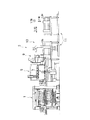
図6には、この発明に係る金型格納装置1を備えた曲げ加工システム3の全体が示されている。図6において、最も左側には、詳細を後述するこの発明に係る金型格納装置1が設けられており、その右側には、金型格納装置1からパンチPおよびダイDをセットとしたステーションが供給されて装着し、ワークWに曲げ加工を行う曲げ加工機としてのプレスブレーキ5が設けられている。
【0024】
このプレスブレーキ5の前面(図6中紙面直交方向手前側)には、プレスブレーキ5の加工位置にワークWを供給するハンドリングロボット7が設けられている。また、プレスブレーキ5の図6中右側面には、前記ハンドリングロボット7のグリッパを交換するためのハンドリングロボットグリッパ交換装置9が設けられている。
【0025】
また、図6中最も右側には、被加工物であるワークWを多量に積載したワーク積載装置11(図6においては2個設けられている)が、前後方向(図6中紙面直交方向)へ移動自在に設けられている。
【0026】
さらに、前記プレスブレーキ5と前記ワーク積載装置11の間、すなわちプレスブレーキ5の前方右側には、ワーク積載装置11により供給されたワークWを一枚取りして前記ハンドリングロボット7に供給するためのワークローディングアンローディングロボット13が図6中左右方向へ移動自在に設けられている。
【0027】
従って、予め多量のワークWが積載されているワーク積載装置11を前後移動させ、ワークローディングアンローディングロボット13を右方向へ移動させてワークWを一枚取りし、このワークローディングアンローディングロボット13を左方向へ移動させる。ハンドリングロボットグリッパ交換装置9により所望のグリッパを装着したハンドリングロボット7が、ワークローディングアンローディングロボット13からワークWを供給されてプレスブレーキ5の加工位置にワークWを供給する。プレスブレーキ5は供給されたワークWに所望の曲げ加工を行うものである。この曲げ加工に当たって、プレスブレーキ5は、加工に最適なパンチPおよびダイDを以下に詳細を示す金型格納装置1により供給されて交換される。
【0028】
次に、図1〜図5に基づいて前述の金型格納装置1を詳細に説明する。この金型格納装置1は、全体が直方体を形成するように、矩形の底面を形成する底面フレーム15と、この底面フレーム15の四隅から上方へ垂直に設けられている柱フレーム17と、この柱フレーム17に支持されている矩形の上フレーム19から成る骨組みを有している。
【0029】
図4、図7および図8を参照するに、前記上フレーム19と同一面に設けられている2本のY軸上部材21間に設けられている左右のX軸上部材23L、23Rには、Y軸送り機構であるY軸上ボールネジ25が回転自在に設けられており、このY軸上ボールネジ25の図4中左端部には図8に示されているようにY軸上モータ27によりチェーン29等の回転伝達部材を介して回転駆動されるスプロケット31が取付けられている。
【0030】
前記Y軸上部材21の下側にはY軸上ガイドレール33が各々Y軸方向に設けられており、このY軸上ガイドレール33に沿ってY軸方向へ移動自在の吊下スライダ35を上面に有するY軸ステーション37が設けられている。このY軸ステーション37には、前述のY軸上ボールネジ25に螺合するY軸上ボールナット39が設けられている。
【0031】
従って、Y軸上モータ27によりチェーン29を介してスプロケット31を回転させてY軸上ボールネジ25を回転させると、Y軸上ボールナット39の作用によりY軸ステーション37がY軸上ガイドレール33に沿ってY軸方向へ移動・位置決めされる。
【0032】
図1を参照するに、前記Y軸ステーション37には2個のステーション37A、37Bが設けられており、一方のステーション37Bは現在プレスブレーキ5において使用されている金型を収容するためのものであり、他方のステーション37Aは新たにプレスブレーキ5に装着する金型を保持するためのものである。このように構成することにより、プレスブレーキ5における加工中に、次の加工に使用する金型を準備することができるため、金型の交換作業を短時間で行うことが可能になる。
【0033】
図3および図9を参照するに、前記底面フレーム15と上フレーム19との間における図2中左右両面には複数(ここでは5個)の柱41が設けられており、この柱41に昇降シリンダ43が各々併設されている。前記柱41の後面(図3中右側)には上下方向にZ軸ガイドレール45が設けられており、このZ軸ガイドレール45に沿ってリフタ47が昇降自在に設けられている。このリフタ47にはパンチPおよびダイDをセットにして搬送するための金型ステーション49が取付けられている。
【0034】
図10(A)、(B)を併せて参照するに、前記金型ステーション49は、上部材51、下部材53、および厚みの小さな柱55からなる矩形のフレームを有しており、図10(A)中左側の上下隅部には金型ステーション49を搬送する際にクランプするクランプベース57が各々設けられている。前記上部材51の下面における前記柱55よりも前方(図10(B)中左側)位置には、X軸方向のほぼ全長にわたってガイドレール59が設けられている。
【0035】
図11を参照するに、このガイドレール59にはローラ61が設けられており、パンチホルダ63をX軸方向へ移動自在に吊下げている。また、ホルダ67の下端部に突出して設けられている取付部69にボルト71によりパンチPの上端部73を取付けている。なお、パンチPの表裏の向きはどちらでも取付可能となっている。
【0036】
前記ホルダ67はガイド62、スライドレール64および吊りボルト66を介してバネ68により上方へ付勢されることにより、パンチホルダ63の下面に固定されており、パンチPを長手方向へ移動させる際には、エアシリンダにて押圧部材70によりバネ68を下方向へ押圧させガイド62を下方に下げ、ホルダ67とパンチホルダ63の接触を解放させることにより行なわれる。
【0037】
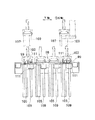
従って、図10(A)に示されているように、金型ステーション49の上部材51には、複数種類の長尺パンチP(例えば100mm幅の長尺パンチP1 を3個と、200mm幅の長尺パンチP2 を2個)がホルダ67を介してパンチホルダ63に接続されており、このパンチホルダ63がガイドレール59に移動自在に取付けられている。なお、前記上部材51の中央部分に設けられている空間75は、後述する長さの短い短尺パンチPSをセットして所望の長さのパンチPを形成するために設けられている。
【0038】
なお、前述の5個の金型ステーション49の内の1個には前述のようなパンチPは装着されておらず空の状態となっており、後から所望のパンチPを装着できるようになっている。
【0039】
一方、図5および図12〜図14を参照するに、底面フレーム15には、X軸方向に2本のX軸下部材77が設けられており、このX軸下部材77の間には2本のY軸下部材79が設けられている。前記X軸下部材77の上側には各々軸受81が設けられており、Y軸下ボールネジ83が回転自在に設けられている。このY軸下ボールネジ83にはスプロケット85が取付けられており、チェーン87を介してY軸下モータ89と連結されている(図2参照)。
【0040】
また、前記Y軸下部材79の上側にはY軸下ガイドレール91が各々設けられている。このY軸下ガイドレール91の上側には、Y軸方向へ移動自在のスライダ93を有するダイステーション95が設けられており、このダイステーション95には前述のY軸下ボールネジ83に螺合するY軸下ボールナット97が取付けられている。
【0041】
従って、Y軸下モータ89によりチェーン87を介してスプロケット85を回転させてY軸下ボールネジ83を回転させると、Y軸下ボールナット97の作用によりダイステーション95がY軸下ガイドレール91に沿ってY軸方向へ移動する。
【0042】
図13および図14を参照するに、前記ダイステーション95には複数個(ここでは4個)の留め金99が設けられている。この留め金99は、種々の形状のダイDや異なる長さのダイDを装着したダイホルダ101をダイステーション95に取付けるためのものであり、ダイホルダ101の底面に設けられている穴に嵌合する突起103を有している。
【0043】
前記留め金99の底面は昇降シリンダ105のピストンロッド107の先端に取付けられると共に昇降ガイドポスト109が取付けられている。この昇降ガイドポスト109はガイド受け111により摺動自在に支持されているので、留め金99は垂直方向にまっすぐに昇降することになる。
【0044】
従って、Y軸下モータ89によりY軸下ボールネジ83を回転駆動させ、Y軸下ガイドレール91に沿ってダイステーション95を所望のパンチPを格納した金型ステーション49の下方へ移動・位置決めする。そして、昇降シリンダ105によりダイDおよびダイホルダ101を上昇させて所望の金型ステーション49に積載する。
【0045】
また、図15を参照するに、Y軸ステーション37の下側におけるX軸方向の両端部(図15中左右両端部)には各々外側へ向かってシリンダ113が設けられており、このシリンダ113のピストンロッド115の先端にはロックピン117が取付けられている。
【0046】
従って、前述のようにして上昇された金型ステーション49は、シリンダ113により外側へ押出されたロックピン117でY軸ステーション37に固定される。なお、Y軸ステーション37の左右両外側には、各々ガイドピン119が鉛直方向に設けられており、金型ステーション49が鉛直上方へ上昇されるようになっている。
【0047】
一方、図5における金型格納装置1の左内側には短尺パンチ格納部121がX軸方向に複数個(ここでは4個)設けられている。図16〜図18を参照するに、この短尺パンチ格納部121では、ベースフレーム123に設けられている上下2段のLMガイド125によりフレーム127が移動自在に支持されており、ベースフレーム123の下面に取付けられているシリンダ128によりX軸方向へ移動自在となっている。このフレーム127の内部には、複数個(ここでは、50mmの短尺パンチPS0 、15mm短尺パンチPS1 、15mm短尺パンチPS2 、10mm短尺パンチPS3 、10mm短尺パンチPS4 、10mm短尺パンチPS5 )の短尺パンチPSが格納されている。
【0048】
図18を参照するに、前記フレーム127の内部に格納されている短尺パンチPSのうち50mm短尺パンチPS0 はクランプ位置においてフレーム127に直接格納されているが、他の5個の短尺パンチPSは前記50mm短尺パンチPS0 のものに対してY軸方向にずれた位置において各々ブラケット129に別個に取付けられている。このブラケット129はフレーム127の上下に設けられているリニアシャフト131に沿ってY軸方向へ移動自在に支持されており、所望の短尺パンチPSを個別シリンダ133により50mm短尺パンチPS0 と並ぶ位置に個別に移動可能となっている。
【0049】
図3、図5、図19および図20を参照するに、前記短尺パンチ格納部121の図3中左側には短尺自動長さチェンジャ135(以下、短尺ALC135という、)が設けられている。この短尺ALC135では、柱フレーム17の間にX軸方向へ梁部材137が設けられており、この梁部材137に設けられたLMガイド139(図19参照)に沿って移動自在のスライダ141に支持されるボールナットベース143が設けられている。また、ボールナットベース143の下方には、前記LMガイド139と平行にX軸方向に延伸してX軸ボールネジ145が回転自在に設けられている。このX軸ボールネジ145の端部にはスプロケット147が取付けられており、チェーン149を介してX軸モータ151により回転駆動される。また、前記ボールナットベース143の下面には、前記X軸ボールネジ145に螺合するX軸ボールナット153が取付けられている。
【0050】
従って、X軸モータ151によりX軸ボールネジ145を回転駆動すると、X軸ボールナット153の作用によりボールナットベース143はX軸方向へ移動・位置決めされることになる。
【0051】
前記ボールナットベース143の上面にはLMベース155がY軸方向に設けられており、このLMベース155に沿ってY軸方向へ移動自在のベース157が設けられている。前記LMベース155の上にはエアーシリンダ159がY軸方向に設けられており、ピストンロッド161の先端は前記ベース157の下面に設けられているブラケット163に取付けられている。
【0052】
前記ベース157の上面には、エアーシリンダ165がY軸方向に設けられており、図19中右方向へ突出自在のピストンロッド167の先端はクランパケース169に接続されている。このクランパケース169の下面にはスライダ171が取付けられており、前記ベース157の上面にY軸方向に設けられているY軸ガイドレール173に沿って移動自在となっている。
【0053】
このクランパケース169の図20中左側には第一エアーシリンダ175と第二エアーシリンダ177が設けられており、内部には前記第一エアーシリンダ175により作動する第一クランパ179および前記第二エアーシリンダ177により作動する第二クランパ181が並設されている。図20中上側に設けられている第一クランパ179は、前述の短尺パンチPSのうち50mm短尺パンチPS0 をクランプするためのものであり、図20中下側に設けられている第二クランパ181は、15mm短尺パンチPS1 〜PS3 および10mm短尺パンチPS4 、PS5 をクランプするためのものである。
【0054】
従って、エアーシリンダ165の作用によりクランパケース169全体をY軸ガイドレール173の沿ってY軸方向へ移動・位置決めして、第一エアーシリンダ175により作動する第一クランパ179が50mm短尺パンチPS0 に設けられている把持部183をクランプし、第二エアーシリンダ177により作動する第二クランパ181が他の短尺パンチPS1 〜PS5 に設けられている把持部183をクランプする。この状態で、エアーシリンダ159により前記短尺パンチPSを前述の金型ステーション49に設けられている空間75に挿入する。
【0055】
図21には、金型ステーション49への短尺パンチPSの取付部が示されている。前述した長尺パンチPの場合と同様に、ガイドレール59のローラ61によりパンチホルダ185がX軸方向へ移動自在に吊下げられている。このパンチホルダ185には、バネ187によりクランプ方向(図21中反時計方向)へ付勢されているレバー189が設けられており、このレバー189の先端がクランプピン191を図21中右方向へ付勢することにより、パンチホルダ185の下端部に設けられている貫通穴193を貫通して短尺パンチPSの上端部に設けられている係止部195を係止する。なお、短尺パンチPSをパンチホルダ185から離脱させる場合には、エジェクタ197によりレバー189の上端部を図21中右側へ押すことにより容易に取外すことができる。また、短尺パンチPSの表裏の向きはどちらでも取付可能となっている。
【0056】
図1中前記短尺ALC135の右側、すなわち前述のようにして短尺パンチPSを取付けた金型ステーション49を挟んで反対側には、長尺自動長さチェンジャ199(以下、長尺ALC199という、)が設けられている。この長尺ALC199は、Y軸ステーション37に装着した長尺パンチPおよび短尺パンチPSを隙間がないように密着させて所定長さのパンチPを得るためのものである。
【0057】
図22〜図24を参照するに、長尺ALC199では、X軸方向に架台201が延伸して設けられており、上フレーム19と底面フレーム15との間に設けられている支柱203(図3参照)における途中高さ位置に両端が固定されている。前記架台201の上にはベースプレート205がX軸方向に取付けられており、このベースプレート205の左右両端部(図22中左右両端部)における上面にはLMブロック207がY軸方向に設けられている。このLMブロック207の上にはLMガイド209がY軸方向へ移動自在に設けられている。また、前記ベースプレート205のX軸方向中央部上面にはエアーシリンダ211がY軸方向に設けられている。
【0058】
前記各LMガイド209の上には、ブラケット213により垂直に保持された本体フレーム215がX軸方向に延伸して設けられており、前述のエアーシリンダ211のピストンロッド217が本体フレーム215に接続されている。また、この本体フレーム215の前面(図24中左側面)の途中高さ位置にはLMガイドレール219がX軸方向に延伸して設けられており、このLMガイドレール219には2個で一組のLMガイド221がX軸方向に2組設けられており、X軸方向へ移動・位置決め自在となっている。
【0059】
前記各組のLMガイド221の前面(図24中左側面)には取付プレート223が各々設けられており、この取付プレート223には先端にピン225を有するブロック227がX軸方向へ複数個(ここでは、3個のものと2個のもの)設けられている。前記本体フレーム215の後面におけるX軸方向両端部には各々エアーシリンダ229が設けられている。この各エアーシリンダ229のピストンロッド231は、ブラケット233を介して各取付プレート223に接続されている。
【0060】
従って、エアーシリンダ229の駆動により取付プレート223に取付けられているピン225をX軸方向の所定位置に位置決めし、エアーシリンダ211の駆動によりLMガイド221をY軸方向に前後移動させることにより、金型ステーション49に装着されている長尺パンチPの係止穴235に前記ピン225を挿入し、再びエアーシリンダ229を駆動することにより長尺パンチPを互いに接近・離反させることができる。
【0061】
図2、図3、図25および図26には前述のようにして所望の長さにセットされたパンチPおよびダイDをプレスブレーキ5に搬入、あるいはプレスブレーキ5に装着されている金型を搬出するための金型搬送装置237が示されている。
【0062】
この金型搬送装置237では、金型を搬送するパスラインPL位置(図3参照)における左右の底面フレーム15の上に受台239が設けられており、この受台239の上には角パイプ製の搬送フレーム241がX軸方向に延伸して設けられており、金型格納装置1から図2中左右に突出している。この搬送フレーム241の上面における図25中左右両端部には軸受243が各々設けられており、搬送用ボールネジ245が回転自在に支持されている。また、搬送用ボールネジ245の図25中左端部にはスプロケット247が取付けられており、搬送用モータ249とチェーン251により連結されている。
【0063】
前記搬送フレーム241の上面にはX軸方向のほぼ全長にわたってLMガイドレール253が設けられている。このLMガイドレール253の上には、前述の搬送用ボールネジ245に螺合するボールナット255を有すると共に下面にスライダ257が設けられた搬送台259がX軸方向へ移動・位置決め自在に設けられている。
【0064】
前記搬送台259には金型ステーション49をクランプするための金型クランプ装置261が設けられている。この金型クランプ装置261では、図26に示されているように金型ステーション49のクランプベース57を左右から挟んでクランプするクランプ爪263がエアーシリンダ265により開閉自在に設けられている。
【0065】
従って、搬送用モータ249により搬送用ボールネジ245を回転駆動して、金型クランプ装置261を図2および図25中最も左側(図2中二点鎖線で示す状態)に移動し、長尺ALC199によりパンチPが所定長さにセットされてパスラインPLに位置決めされた金型ステーション49のクランプベース57を、エアーシリンダ265で作動するクランプ爪263によりクランプする。再び搬送用モータ249により搬送用ボールネジ245を回転駆動して、金型ステーション49を把持した金型クランプ装置261を図2中右方向へ移動させてプレスブレーキ5の内部に金型ステーション49を供給する。
【0066】
次に、前述の金型格納装置1において所望の長さのパンチPの作成およびこのパンチPに適するダイDとの組合わせを行い、プレスブレーキ5に装着する手順全体について説明する。
【0067】
まず、図10(A)に示されているように、金型ステーション49の上部材51に所望の長さに対応した長さの複数の長尺のパンチPが装着されている金型ステーション49を選択する。例えば、図10(A)では、100mm幅のパンチP1を3個と、200mm幅のパンチP2を2個X軸方向に移動自在に有している。なお、前記上部材51の中央部分に設けられている空間75は、後述する長さの短い短尺パンチPSをセットして所望の長さのパンチPを形成するために設けられている。
【0068】
次いで、前述のパンチPに対応するダイDの選択を行う。図2および図12〜14を参照するに、Y軸下モータ89によりチェーン87を介してスプロケット85を回転させてY軸下ボールネジ83を回転させると、Y軸下ボールナット97の作用によりダイステーション95がY軸下ガイドレール91に沿ってY軸方向へ移動するので所望のパンチPを格納した金型ステーション49の下方へ移動・位置決めする。そして、昇降シリンダ105によりダイDおよびダイホルダ101を上昇させて所望の金型ステーション49に積載する。
【0069】
図3および図9を参照するに、このようにしてダイDが積載された金型ステーション49は、昇降シリンダ43によりリフタ47を上昇させて、図15に示されているように、シリンダ113により外側へ押出されたロックピン117でY軸ステーション37に固定される。その後、昇降シリンダ43によりリフタ47を下降させて元の位置に戻す。また、Y軸ステーション37に短尺パンチPSを装着すべくY軸上モータ27によりY軸上ボールネジ25を回転させて、Y軸ステーション37を図1中Y軸方向左側へ移動させ長尺ALC199と短尺ALC135の間まで下降させておく。
【0070】
次に、短尺パンチPSの組合わせを行う。図3および図16〜図20を参照するに、例えば75mmのパンチPが必要な場合には、X軸モータ151によりX軸ボールネジ145を回転させて短尺ALC135をX軸方向へ移動させ、所望の短尺パンチPSを格納してある短尺パンチ格納部121の前へ移動する。そして、第一クランパ179を短尺パンチ格納部121の50mm短尺パンチPS0 の前方へ位置決めする。エアーシリンダ165によりクランパケース169を図20中右方向へ移動させて第一クランパ179を50mm短尺パンチPS0 に接近させ、第一エアーシリンダ175により第一クランパ179を作動させて50mm短尺パンチPS0 をクランプする。
【0071】
次に、個別シリンダ133により使用する15mm短尺パンチPS2 と10mm短尺パンチPS3を図18中Y軸方向上側へ移動させてクランプ位置に位置決めし、シリンダ128により短尺パンチ格納部121を図16中X軸方向右方向へ移動させて50mm短尺パンチPS0 に接触するように位置決めする。第二エアーシリンダ177を作動させて第二クランパ181により15mm短尺パンチPS2 と10mm短尺パンチPS3 をクランプする。ここで、15mm短尺パンチPS2 と10mm短尺パンチPS3 を選択したのは、25mmの長さの短尺パンチPSを隙間なく作成するのに最適であり、他の15mm短尺パンチPS1 や10mm短尺パンチP4 等を使用すると隙間があいてしまうためである。
【0072】
以上のようにして、所望の長さ(ここでは75mm)のパンチPを作成した後、X軸モータ151によりX軸ボールネジ145を回転させて短尺ALC135をX軸方向へ移動させ、図10(A)に示されている金型ステーション49の短尺パンチ取付位置である中央部分の空間75に対応する位置に位置決めする。
【0073】
短尺ALC135に設けられているエアーシリンダ165のピストンロッド167をY軸方向右へ伸ばして、第一クランパ179により50mm短尺パンチPSの把持部183をクランプすると共に、第二クランパ181により15mm短尺パンチPS2 と10mm短尺パンチPS3 をクランプする。
【0074】
そして、エアーシリンダ159をY軸方向右側へ伸ばして、クランプされている短尺パンチPSをY軸ステーション37に装着されている金型ステーション49の中央部分に設けてある空間75に挿入する。短尺パンチPSは、金型ステーション49のパンチホルダ185に設けられているクランプピン191が短尺パンチPSの係止部195に嵌合することによりパンチホルダ185に固定される(図21参照)。
【0075】
次に、図22〜図24を参照するに、長尺ALC199のエアーシリンダ229の駆動により取付プレート223に取付けられているピン225をX軸方向の所定位置に位置決めし、エアーシリンダ211の駆動によりLMガイド209に沿ってY軸方向に前後移動させることにより、Y軸ステーション37に装着されている長尺パンチPの係止穴235に前記ピン225を挿入する。その後、エアーシリンダ229を駆動することにより長尺パンチPを中央側へ移動させて、両側にある長尺パンチPと中央部の短尺パンチPSを隙間なく接触させる。
【0076】
このようにしてパンチPを所望の長さにセットした後、再度金型ステーション49を上昇させて前述と同様にしてY軸ステーション37に連結する。Y軸ステーション37をパスラインPL位置まで移動させ、金型搬送装置237の金型クランプ装置261によりパスラインPL位置に位置決めされている金型ステーション49のクランプベース57をクランプする。最後に、搬送用モータ249により搬送用ボールネジ245を回転駆動して、金型クランプ装置261を図25中右方向へ移動させてプレスブレーキ5の内部に金型ステーション49を供給した後、金型格納装置1の図25中左側位置まで戻る。
【0077】
ここで、プレスブレーキ5における金型ステーション49の取付および取外しは、特開平7−116734号公報によりすでに既知のものとなっているのでプレスブレーキ5の内部における構成および動作の説明を省略する。
【0078】
以上の結果から、パンチPを長尺パンチPと短尺パンチPSとの組合わせで構成し、種々の長さのパンチPを予め金型格納装置1に格納してあるので、金型の交換時に所望の長さのパンチPを作成することができる。また、作製されたパンチPと組合わせるダイDも複数格納してあるので、適切な組合わせを行うことができる。この金型格納装置1における作業は、プレスブレーキ5とは独立して行うことができるので、プレスブレーキ5における加工中に次に使用する金型を準備することができる。これにより、加工効率を向上させることができる。
【0079】
また、パンチPとダイDを一組としてプレスブレーキ5に供給するので、パンチPに対応したダイDを間違いなく供給することができると共に、金型格納装置1において金型の芯だしを行うことができる。これにより、プレスブレーキ5における金型交換を容易且つ迅速に行うことができる。
【0080】
また、Y軸ステーション37が金型を搬送するための金型ステーション49を2個有しているので、プレスブレーキ5から取外した金型を格納した金型ステーション49と、これからプレスブレーキ5に搬送する金型ステーション49を同時に保持することができるので、迅速に金型交換を行うことができる。
【0081】
なお、この発明は前述の実施の形態に限定されることなく、適宜な変更を行なうことにより、その他の態様で実施し得るものである。
【0082】
【発明の効果】
以上説明したように、請求項1の発明による曲げ加工機における金型交換方法では、金型格納装置に複数の長尺パンチが格納されているので、適切な長尺パンチを選択することができる。また、複数の短尺パンチも格納されているので、適正な短尺パンチを選択して長尺パンチと組合わせることにより所望の長さのパンチを作成することができる。また、所望のパンチに対応するダイを選択して前記パンチを組込んだ金型ステーションに装着することにより、パンチおよびダイの選択と芯合わせが同時に行われる。このため、所望の長さのパンチとこのパンチに対応するダイを同時に曲げ加工機に搬入するので、迅速且つ容易に金型の交換を行うことができる。
【0083】
請求項2の発明による曲げ加工機における金型交換方法では、選択された複数の短尺パンチは隙間が無いように密着して一個の短尺パンチとして金型ステーションに装着されるので、組合わせにより所望の長さの短尺パンチを作製することができる。
【0084】
請求項3の発明による曲げ加工機における金型交換方法では、作製された短尺パンチを長尺パンチの間に挿入して金型ステーションに取付、両側の長尺パンチを接近させることにより隙間があかないように密着させるので、所望の長さの完全なパンチを得ることができる。
【0085】
請求項4の発明による曲げ加工機における金型格納装置では、金型格納装置に複数の長尺パンチが格納されている複数の金型ステーションがあるので、適切な金型ステーションを選択することにより適切な長尺パンチを選択することができる。また、金型格納装置の短尺パンチ格納部に複数の短尺パンチが格納されているので、適正な短尺パンチを選択して前記金型ステーションにおいて長尺パンチと組合わせることにより所望の長さのパンチを作成することができる。また、複数のダイを格納してあるダイステーションから前記所望のパンチに対応するダイを選択して前記金型ステーションに装着することにより、パンチおよびダイの選択と芯合わせが同時に行われる。このようにして所望のパンチおよびダイを装着した金型ステーションをY軸ステーションにより搬送位置に移動させ、金型搬送装置により所望の長さのパンチとこのパンチに対応するダイを同時に曲げ加工機に搬入するので、迅速且つ容易に金型の交換を行うことができる。
【0086】
請求項5の発明による曲げ加工機の金型格納装置では、複数のダイを格納したダイステーションが設けられているので、所望のパンチに対応するダイを選択することができる。また金型格納装置が曲げ加工機に隣接して設けて設けてあるので金型交換を迅速に行うことができる。
【図面の簡単な説明】
【図1】この発明に係る金型格納装置の内部を示す断面図である。
【図2】図1中II方向から見た側面図である。
【図3】図2中III 方向から見た正面図である。
【図4】図1中IV方向から見た平面図である。
【図5】図1中V −V 向から見た断面図である。
【図6】この発明に係る曲げ加工システムの全体を示す正面図である。
【図7】Y軸ステーションを示す平面図である。
【図8】図7中VIII方向から見た側面図である。
【図9】図3中IX−IX線に沿った断面図である。
【図10】(A)、(B)は金型ステーションを示す正面図および側面図である。
【図11】長尺パンチの金型ステーションに対する取付部を示す拡大図である。
【図12】ダイステーションの移動機構を示す側面図である。
【図13】ダイステーションを示す正面図である。
【図14】ダイステーションにおけるダイを金型ステーションに取付ける状態を示す説明図である。
【図15】金型ステーションをY軸ステーションに取付ける取付部を示す正面図である。
【図16】短尺パンチ格納部を示す正面図である。
【図17】図16中XVII方向から見た側面図である。
【図18】図16中XVIII 方向から見た平面図である。
【図19】短尺ALCを示す正面図である。
【図20】図19中XX方向から見た平面図である。
【図21】短尺パンチの金型ステーションに対する取付部を示す拡大図である。
【図22】(A)、(B)は長尺ALCを示す平面図および正面図である。
【図23】長尺ALCにおけるX軸方向移動機構を示す平面図である。
【図24】図22中XXIV−XXIV線に沿った断面図である。
【図25】金型搬送装置を示す断面図である。
【図26】金型クランプ装置を示す平面図である。
【図27】従来におけるパンチの長さの調整方法を示す説明図である。
【符号の説明】
1 金型格納装置
3 曲げ加工システム
5 プレスブレーキ(曲げ加工機)
7 ハンドリングロボット
11 板材積載装置
13 ローディング・アンローディングロボット
37 Y軸ステーション
49 金型ステーション
95 ダイステーション
121 短尺パンチ格納部
135 短尺ALC
199 長尺ALC
237 金型搬送装置
P パンチ、長尺パンチ
D ダイ
PS 短尺パンチ[0001]
BACKGROUND OF THE INVENTION
The present invention relates to a mold exchanging method, a mold storage device, and a bending system in a bending machine.
[0002]
[Prior art]
Conventionally, punches and dies, which are molds used in press brakes as bending machines, store a plurality of punches with predetermined lengths in an upper table, and these punches are used as a chain mechanism or a link mechanism. The desired punch corresponding to the size of the workpiece is selected by turning it.
[0003]
However, when using a punch having a predetermined length, there is no problem when a punch having a desired length is stored, but when a punch having an appropriate length is not stored. May not be processed properly. In addition, there is a problem that the front and back cannot be selected even when the front and back of the punch are determined depending on the content of processing.
[0004]
In order to solve such a problem, as shown in FIG. 27, a plurality of punches P divided in the longitudinal direction of the upper table 301 (left and right direction in FIG. 27) are mounted so as to have a desired length. The punch P has been moved to the central portion, or unnecessary punches P have been moved to both ends to make the length appropriate.
[0005]
[Problems to be solved by the invention]
However, even if the punch P is attached as shown in FIG. 27, the overall length of the punch P can be adjusted, but the shape and front / back of the punch P cannot be selected. is there.
[0006]
The object of the present invention is made by paying attention to the conventional techniques as described above, and is to select a mold having an optimum shape for processing, set it to a desired length, and convey it to a bending machine. It is an object of the present invention to provide a mold exchanging method, a mold storage device, and a bending system in a bending machine capable of performing the above.
[0007]
[Means for Solving the Problems]
In order to achieve the above object, a die changing method in the bending machine of the invention according to claim 1 is:A mold exchanging method in a bending machine for bending a plate material by cooperation of a punch and a die includes the following steps.
(1) A first long punch group formed by combining long punches having a width of 100 mm and a second long punch group formed by combining long punches having a width of 200 mm are movably provided. Between the long punch group and the second long punch group, there is provided a space in which a short punch group formed by combining short punches having a width of 50 mm, 15 mm or 10 mm can be mounted movably and a die can be mounted. Selecting a mold station having a desired long punch group from a plurality of mold stations;
(2) From the die station storing a plurality of diesSelecting a die corresponding to the combined length of the desired long punch group and short punch group selected in step (1);
(3) The aboveStep (2)A step of attaching the die selected in step 1 to the mold station,
(4) A step of creating a short punch having a desired length by combining the short punches,
(5) In the mold station,A step of creating a punch having a desired length by combining the first and second long punch groups in the step (1) and the short punch having a desired length in the step (4);
(6) The aboveStep (5)The process of transporting the mold station to the bending machine,
[0009]
Therefore, an appropriate long punch is selected from the long punches stored in the mold storage device, and the short punch is selected to form a punch having a desired length in combination with this long punch. Combine these at the station. Further, a die corresponding to a desired punch is selected and mounted on the mold station together with the created punch. In this way, a die station in which a punch having a desired length and a die corresponding to the punch are mounted at the same core position is carried into a bending machine, and the die is exchanged.
[0010]
A method for exchanging dies in a bending machine according to
[0011]
Accordingly, the selected plurality of short punches are brought into close contact with each other so that there is no gap, and are mounted on the mold station as one short punch.
[0012]
The method for exchanging dies in a bending machine according to claim 3 is the method according to claim 1.After the step (5) has mounted the short punch produced in the step (4) between the first long punch group and the second long punch group mounted on the mold station The first long punch group, the second long punch group, and the short punch are brought close to each other to bring the punches into close contact with each other.
[0013]
Therefore, the produced short punch is inserted between the long punches and attached to the mold station, and the long punches on both sides are brought close to each other so that there is no gap.
[0014]
The die changer in the bending machine of the invention according to claim 4 is:A mold storage apparatus in a bending machine for bending a plate material by cooperation of a punch and a die, a first long punch group formed by combining long punches having a width of 100 mm, and a long member having a width of 200 mm A second long punch group comprising a combination of punches is provided so as to be able to approach and separate from each other, and a width of 50 mm, 15 mm or 10 mm is provided between the first long punch group and the second long punch group. A plurality of molds having a space in which a short punch group formed by combining the short punches can be mounted, and a die can be mounted at the same core position below the first and second long punch groups and the short punch group A plurality of short punch storages including a station, a Y axis station that transports a mold station selected from the plurality of mold stations in the Y axis direction, and a plurality of short punches. And a short automatic length in which the plurality of short punches selected in the short punch storage unit are closely contacted with each other without gaps and the contacted short punches are mounted on the mold station conveyed by the Y-axis station. A changer, a long automatic length changer that closely contacts the first long punch group, the second long punch group, and the short punch mounted on the mold station without any gaps, and the first long length A die conveyance device that comprises a punch group, the second long punch group, and the short punch group, and a die conveying device that conveys the die station having a corresponding die to a bending machine. Is a thing.
[0015]
Therefore, a die station equipped with an appropriate long punch is selected from the long punches stored in the die storage device, and the die corresponding to the long punch is aligned with the same die station. After mounting, the mold station is moved to a predetermined position by the Y-axis station. The short automatic length changer selects a proper short punch from the short punch storing portion to produce a punch having a desired length in combination with the long punch, and is moved by the Y-axis station. These are combined at the station, and the long automatic length changer brings the combined long punch and short punch into close contact. In this way, a mold station on which a punch having a desired length and a die corresponding to the punch are mounted is carried into the bending machine, and the mold is exchanged.
[0016]
The mold exchanging device in the bending machine of the invention according to
[0017]
Therefore, this can be done by selecting the die corresponding to the desired punch.In addition, since the mold storage device is provided adjacent to the bending machine, the mold can be exchanged quickly..
[0022]
DETAILED DESCRIPTION OF THE INVENTION
Hereinafter, embodiments of the present invention will be described in detail with reference to the drawings.
[0023]
FIG. 6 shows the entire bending system 3 including the mold storage device 1 according to the present invention. In FIG. 6, a mold storage device 1 according to the present invention, which will be described in detail later, is provided on the leftmost side, and on the right side is a station in which a punch P and a die D are set from the mold storage device 1. A
[0024]
A handling
[0025]
Further, on the rightmost side in FIG. 6, a workpiece loading device 11 (two pieces are provided in FIG. 6) on which a large number of workpieces W as workpieces are loaded is a front-rear direction (a direction perpendicular to the paper surface in FIG. 6). It is provided to move freely.
[0026]
Furthermore, a piece of workpiece W supplied by the
[0027]
Accordingly, the
[0028]
Next, the above-described mold storage device 1 will be described in detail with reference to FIGS. The mold storage device 1 includes a
[0029]
4, 7 and 8, the left and right X-axis upper members 23 </ b> L and 23 </ b> R provided between the two Y-axis
[0030]
On the lower side of the Y-axis
[0031]
Accordingly, when the
[0032]
Referring to FIG. 1, the Y-
[0033]
3 and 9, a plurality of (here, five)
[0034]
10A and 10B, the
[0035]
Referring to FIG. 11, a
[0036]
The
[0037]
Accordingly, as shown in FIG. 10A, the
[0038]
Note that one of the five
[0039]
On the other hand, referring to FIG. 5 and FIGS. 12 to 14, the
[0040]
Further, Y-axis
[0041]
Accordingly, when the
[0042]
Referring to FIGS. 13 and 14, the
[0043]
The bottom surface of the
[0044]
Therefore, the Y-axis
[0045]
Referring to FIG. 15,
[0046]
Therefore, the
[0047]
On the other hand, a plurality (four in this case) of short
[0048]
Referring to FIG. 18, among the short punches PS stored in the
[0049]
Referring to FIGS. 3, 5, 19, and 20, a short automatic length changer 135 (hereinafter referred to as a short ALC 135) is provided on the left side of the short
[0050]
Therefore, when the
[0051]
An
[0052]
An
[0053]
A
[0054]
Accordingly, the
[0055]
FIG. 21 shows the attachment part of the short punch PS to the
[0056]
In FIG. 1, a long automatic length changer 199 (hereinafter referred to as a long ALC 199) is provided on the right side of the
[0057]
22 to 24, in the
[0058]
On each
[0059]
A mounting
[0060]
Accordingly, the
[0061]
2, 3, 25, and 26, the punch P and the die D set to a desired length as described above are carried into the
[0062]
In the
[0063]
An
[0064]
The transport table 259 is provided with a
[0065]
Accordingly, the conveying
[0066]
Next, the overall procedure for creating a punch P having a desired length and combining it with a die D suitable for the punch P in the mold storage device 1 and mounting the punch P on the
[0067]
First, as shown in FIG. 10A, a
[0068]
Next, the die D corresponding to the aforementioned punch P is selected. 2 and 12 to 14, when the
[0069]
Referring to FIGS. 3 and 9, the
[0070]
Next, the short punch PS is combined. Referring to FIG. 3 and FIG. 16 to FIG. 20, for example, when a 75 mm punch P is necessary, the
[0071]
Next, 15mm short punch PS used by
[0072]
As described above, after a punch P having a desired length (75 mm in this example) is formed, the
[0073]
The
[0074]
Then, the
[0075]
Next, referring to FIGS. 22 to 24, the
[0076]
After setting the punch P to a desired length in this way, the
[0077]
Here, since the attachment and removal of the
[0078]
From the above results, the punch P is composed of a combination of the long punch P and the short punch PS, and the punches P of various lengths are stored in the mold storage device 1 in advance. A punch P having a desired length can be created. In addition, since a plurality of dies D to be combined with the manufactured punch P are stored, an appropriate combination can be performed. Since the work in the mold storage device 1 can be performed independently of the
[0079]
Further, since the punch P and the die D are supplied to the
[0080]
Further, since the Y-
[0081]
The present invention is not limited to the above-described embodiment, and can be implemented in other modes by making appropriate modifications.
[0082]
【The invention's effect】
As described above, in the mold exchanging method in the bending machine according to the first aspect of the present invention, since a plurality of long punches are stored in the mold storage device, an appropriate long punch can be selected. . Further, since a plurality of short punches are also stored, a punch having a desired length can be created by selecting an appropriate short punch and combining it with the long punch. Further, by selecting a die corresponding to a desired punch and mounting it on a mold station incorporating the punch, the punch and die are selected and aligned at the same time. For this reason, a punch having a desired length and a die corresponding to the punch are simultaneously carried into the bending machine, so that the mold can be replaced quickly and easily.
[0083]
In the mold exchanging method in the bending machine according to the second aspect of the invention, the selected plurality of short punches are closely attached so as not to have a gap and are mounted on the mold station as a single short punch. It is possible to produce a short punch having a length of.
[0084]
In the mold changing method in the bending machine according to the invention of claim 3, the produced short punch is inserted between the long punches and attached to the mold station, and the long punches on both sides are brought close to each other so that there is a gap. As a result, it is possible to obtain a complete punch having a desired length.
[0085]
In the mold storage device in the bending machine according to the invention of claim 4, since there are a plurality of mold stations in which a plurality of long punches are stored in the mold storage device, by selecting an appropriate mold station An appropriate long punch can be selected. In addition, since a plurality of short punches are stored in the short punch storage portion of the mold storage device, a punch having a desired length is selected by selecting an appropriate short punch and combining it with the long punch at the mold station. Can be created. Further, by selecting a die corresponding to the desired punch from a die station storing a plurality of dies and mounting the die on the mold station, the punch and die are selected and aligned at the same time. In this way, the die station on which the desired punch and die are mounted is moved to the transfer position by the Y-axis station, and the punch having the desired length and the die corresponding to this punch are simultaneously turned into a bending machine by the die transfer device. Since it carries in, a metal mold | die can be replaced | exchanged quickly and easily.
[0086]
In the die storage apparatus for a bending machine according to the fifth aspect of the present invention, since a die station storing a plurality of dies is provided, a die corresponding to a desired punch can be selected.In addition, since the mold storage device is provided adjacent to the bending machine, the mold can be exchanged quickly..
[Brief description of the drawings]
FIG. 1 is a cross-sectional view showing the inside of a mold storage device according to the present invention.
FIG. 2 is a side view seen from the direction II in FIG.
FIG. 3 is a front view seen from the direction III in FIG. 2;
4 is a plan view seen from the IV direction in FIG. 1. FIG.
FIG. 5 is a cross-sectional view seen from the direction V-V in FIG.
FIG. 6 is a front view showing the entire bending system according to the present invention.
FIG. 7 is a plan view showing a Y-axis station.
8 is a side view seen from the direction VIII in FIG. 7. FIG.
9 is a cross-sectional view taken along line IX-IX in FIG.
FIGS. 10A and 10B are a front view and a side view showing a mold station, respectively.
FIG. 11 is an enlarged view showing an attachment portion of a long punch to a mold station.
FIG. 12 is a side view showing a moving mechanism of the die station.
FIG. 13 is a front view showing a die station.
FIG. 14 is an explanatory view showing a state in which a die in the die station is attached to the mold station.
FIG. 15 is a front view showing an attachment portion for attaching the mold station to the Y-axis station.
FIG. 16 is a front view showing a short punch storage unit.
FIG. 17 is a side view seen from the XVII direction in FIG.
18 is a plan view seen from the XVIII direction in FIG.
FIG. 19 is a front view showing a short ALC.
20 is a plan view seen from the XX direction in FIG.
FIG. 21 is an enlarged view showing a mounting portion of a short punch for a die station.
22A and 22B are a plan view and a front view showing a long ALC.
FIG. 23 is a plan view showing an X-axis direction moving mechanism in a long ALC.
24 is a cross-sectional view taken along line XXIV-XXIV in FIG.
FIG. 25 is a cross-sectional view showing a mold conveying device.
FIG. 26 is a plan view showing a mold clamping device.
FIG. 27 is an explanatory view showing a conventional method for adjusting the punch length.
[Explanation of symbols]
1 Mold storage device
3 Bending system
5 Press brake (bending machine)
7 Handling robot
11 Plate material loading device
13 Loading / unloading robot
37 Y-axis station
49 Mold Station
95 Die Station
121 Short punch storage
135 Short ALC
199 Long ALC
237 Mold transfer device
P punch, long punch
D die
PS short punch
Claims (5)
(1)100mm幅の長尺パンチを組み合わせてなる第1の長尺パンチ群と、200mm幅の長尺パンチを組み合わせてなる第2の長尺パンチ群とを移動可能に有し、前記第1の長尺パンチ群と前記第2の長尺パンチ群との間に50mm、15mmまたは10mm幅の短尺パンチを組み合わせてなる短尺パンチ群を移動可能に装着可能な空間を備えると共にダイを装着可能な複数の金型ステーションから所望の長尺パンチ群を有する金型ステーションを選択する工程、
(2)複数のダイを格納してあるダイステーションから前記工程(1)で選択された所望の長尺パンチ群と短尺パンチ群とを合わせた長さに対応するダイを選択する工程、
(3)前記工程(2)で選択されたダイを前記金型ステーションに装着する工程、
(4)前記短尺パンチを組合わせて所望の長さの短尺パンチを作成する工程、
(5)前記金型ステーションにおいて前記工程(1)の第1および第2の長尺パンチ群と前記工程(4)の所望の長さの短尺パンチを組合わせて所望の長さのパンチを作成する工程、
(6)前記工程(5)の金型ステーションを曲げ加工機に搬送する工程、 A mold exchanging method in a bending machine for bending a plate material in cooperation with a punch and a die, comprising the following steps.
(1) A first long punch group formed by combining long punches having a width of 100 mm and a second long punch group formed by combining long punches having a width of 200 mm are movably provided. Between the long punch group and the second long punch group, there is provided a space in which a short punch group formed by combining short punches having a width of 50 mm, 15 mm or 10 mm can be mounted movably and a die can be mounted. Selecting a mold station having a desired long punch group from a plurality of mold stations;
(2) A step of selecting a die corresponding to the combined length of the desired long punch group and the short punch group selected in the step (1) from a die station storing a plurality of dies ,
(3) A step of mounting the die selected in the step (2) on the mold station ;
(4) A step of creating a short punch having a desired length by combining the short punches ;
(5) A punch having a desired length is produced by combining the first and second long punch groups in the step (1) and the short punch having a desired length in the step (4) in the mold station. The process of
(6) A step of conveying the mold station of the step (5) to a bending machine ,
記載の曲げ加工機における金型交換方法。Wherein the step (4), have a plurality kinds of selecting a desired short punches length from the short punches storage unit that stores a short punch, step of adhering the selected short punches so that no gaps The method for exchanging dies in a bending machine according to claim 1, wherein:
Priority Applications (1)
| Application Number | Priority Date | Filing Date | Title |
|---|---|---|---|
| JP16456097A JP3841923B2 (en) | 1997-06-20 | 1997-06-20 | Mold changing method, mold storage device and bending system in bending machine |
Applications Claiming Priority (1)
| Application Number | Priority Date | Filing Date | Title |
|---|---|---|---|
| JP16456097A JP3841923B2 (en) | 1997-06-20 | 1997-06-20 | Mold changing method, mold storage device and bending system in bending machine |
Publications (2)
| Publication Number | Publication Date |
|---|---|
| JPH1110235A JPH1110235A (en) | 1999-01-19 |
| JP3841923B2 true JP3841923B2 (en) | 2006-11-08 |
Family
ID=15795492
Family Applications (1)
| Application Number | Title | Priority Date | Filing Date |
|---|---|---|---|
| JP16456097A Expired - Fee Related JP3841923B2 (en) | 1997-06-20 | 1997-06-20 | Mold changing method, mold storage device and bending system in bending machine |
Country Status (1)
| Country | Link |
|---|---|
| JP (1) | JP3841923B2 (en) |
Families Citing this family (6)
| Publication number | Priority date | Publication date | Assignee | Title |
|---|---|---|---|---|
| JP4582621B2 (en) * | 2003-06-23 | 2010-11-17 | 株式会社アマダ | Bending machine |
| JP6618576B1 (en) * | 2018-07-17 | 2019-12-11 | 株式会社アマダホールディングス | Method of mounting split upper die on upper die holder provided on upper table in press brake, die changing device, and die stocker |
| CN112423909B (en) * | 2018-07-17 | 2022-12-30 | 株式会社天田集团 | Method for attaching divided upper die to upper die holder provided on upper table in bending machine, device for replacing metal die, and metal die stocker |
| WO2020017539A1 (en) * | 2018-07-17 | 2020-01-23 | 株式会社アマダホールディングス | Tool for press brake |
| EP3970875B1 (en) * | 2019-05-16 | 2024-04-03 | Amada Co., Ltd. | Bending system and correcting method for tool misalignment |
| JP6741824B1 (en) * | 2019-05-16 | 2020-08-19 | 株式会社アマダ | Bending system and die transfer method |
-
1997
- 1997-06-20 JP JP16456097A patent/JP3841923B2/en not_active Expired - Fee Related
Also Published As
| Publication number | Publication date |
|---|---|
| JPH1110235A (en) | 1999-01-19 |
Similar Documents
| Publication | Publication Date | Title |
|---|---|---|
| JP3841923B2 (en) | Mold changing method, mold storage device and bending system in bending machine | |
| JP2002219535A (en) | Method and apparatus for off-line setting up finger for transfer feeder | |
| JP4401482B2 (en) | Matrix-type tool magazine | |
| WO1995000267A1 (en) | Punching press and die mounting method | |
| US5992209A (en) | Transfer press having a lateral depositing arrangement for the tooling | |
| JP4785238B2 (en) | Punch press | |
| JP2003136144A (en) | Bending apparatus | |
| JP3527371B2 (en) | Laser processing machine, work transfer device of laser processing machine, and transfer device for transferring work | |
| JP3765887B2 (en) | Mold separator | |
| JP3987146B2 (en) | Tool block changer | |
| JPH0646590Y2 (en) | Automatic tool changer for multi-stage press forming machine | |
| JP3710899B2 (en) | Sheet material processing machine equipped with sheet material processing method and sheet material carry-in / out device | |
| JP2855942B2 (en) | Flexible transfer machine | |
| JP2843130B2 (en) | Turret punch press with ATC device | |
| JPH10323726A (en) | Mold exchange and device therefor in punching press | |
| JPH04238633A (en) | Device for transferring transfer press | |
| KR940001459Y1 (en) | Automatic exchanging device for pallet | |
| JPH10180369A (en) | Method for tool-block carrying-in and device therefor | |
| JPS6040249Y2 (en) | Young head exchange device | |
| JP2001038567A (en) | Exchange system for work mounting jig pallet | |
| JP3360904B2 (en) | Automatic pusher finger changer | |
| JPH07132332A (en) | Punch press and method for attaching die | |
| JPH0910868A (en) | Sheet transferring device of transfer press and sheet transferring method | |
| JPH0158012B2 (en) | ||
| JPH11204670A (en) | Method and device for marking |
Legal Events
| Date | Code | Title | Description |
|---|---|---|---|
| A621 | Written request for application examination |
Free format text: JAPANESE INTERMEDIATE CODE: A621 Effective date: 20040525 |
|
| A131 | Notification of reasons for refusal |
Free format text: JAPANESE INTERMEDIATE CODE: A131 Effective date: 20060228 |
|
| A521 | Written amendment |
Free format text: JAPANESE INTERMEDIATE CODE: A523 Effective date: 20060419 |
|
| TRDD | Decision of grant or rejection written | ||
| A01 | Written decision to grant a patent or to grant a registration (utility model) |
Free format text: JAPANESE INTERMEDIATE CODE: A01 Effective date: 20060808 |
|
| A61 | First payment of annual fees (during grant procedure) |
Free format text: JAPANESE INTERMEDIATE CODE: A61 Effective date: 20060809 |
|
| R150 | Certificate of patent or registration of utility model |
Free format text: JAPANESE INTERMEDIATE CODE: R150 |
|
| FPAY | Renewal fee payment (event date is renewal date of database) |
Free format text: PAYMENT UNTIL: 20100818 Year of fee payment: 4 |
|
| FPAY | Renewal fee payment (event date is renewal date of database) |
Free format text: PAYMENT UNTIL: 20100818 Year of fee payment: 4 |
|
| FPAY | Renewal fee payment (event date is renewal date of database) |
Free format text: PAYMENT UNTIL: 20110818 Year of fee payment: 5 |
|
| FPAY | Renewal fee payment (event date is renewal date of database) |
Free format text: PAYMENT UNTIL: 20120818 Year of fee payment: 6 |
|
| FPAY | Renewal fee payment (event date is renewal date of database) |
Free format text: PAYMENT UNTIL: 20120818 Year of fee payment: 6 |
|
| FPAY | Renewal fee payment (event date is renewal date of database) |
Free format text: PAYMENT UNTIL: 20130818 Year of fee payment: 7 |
|
| LAPS | Cancellation because of no payment of annual fees |