JP3840076B2 - Image processing apparatus and method, computer program, and storage medium - Google Patents
Image processing apparatus and method, computer program, and storage medium Download PDFInfo
- Publication number
- JP3840076B2 JP3840076B2 JP2001259465A JP2001259465A JP3840076B2 JP 3840076 B2 JP3840076 B2 JP 3840076B2 JP 2001259465 A JP2001259465 A JP 2001259465A JP 2001259465 A JP2001259465 A JP 2001259465A JP 3840076 B2 JP3840076 B2 JP 3840076B2
- Authority
- JP
- Japan
- Prior art keywords
- encoding
- data
- image area
- image
- encoded
- Prior art date
- Legal status (The legal status is an assumption and is not a legal conclusion. Google has not performed a legal analysis and makes no representation as to the accuracy of the status listed.)
- Expired - Fee Related
Links
Images


Description
【0001】
【発明の属する技術分野】
本発明は、画像データを該画像データに付随する像域情報を一定符号量以内に圧縮符号化する機能を有する画像処理装置に関するものである。
【0002】
【従来の技術】
従来,静止画像の圧縮方式には,離散コサイン変換を利用したJPEG方式や,Wavelet変換を利用した方式が多く使われている.この種の符号化方式は,可変長符号化方式であるので,符号化対象の画像毎に符号量が変化する。
【0003】
国際標準化方式であるJPEG方式では,画像に対して1組の量子化マトリクスしか定義できないので、プリスキャン無しには、符号量調整が行なえず、限られたメモリに記憶するシステムで使用する場合においては、メモリオーバーを起こす危険性があった。
【0004】
これを防止するために、予定した符号量よりオーバーした場合は、圧縮率を変更して、原稿の再読み込みを行なう方法や、予めプリスキャンによる符号量見積もりを行ない、符号量を調整するために,量子化パラメータの再設定を行なう方法などがとられていた。
【0005】
一方、画像情報には、元の画像データ以外に、該画像データに付随する像域情報というものがある。像域情報は主に、画像出力時の見栄えを良くするために、画像出力部での色処理や諧調数の調整に用いられる。有彩色と無彩色が混在する自然画像と、原稿中に多く見られる黒文字とでは、同じ黒色でも使用するインクの種類を変えることで、自然画像を自然画像らしく見せる一方で、鮮明な文字を出力することが出来る。
【0006】
このように、画素毎に、有彩色か無彩色、文字部かそうでないか、といった各々1ビットの属性フラグデータを持つことにより、画像出力時、特にプリントアウト時に出力画像の画質向上を図ることが出来る。像域情報には前記以外の他の情報もある。
【0007】
画像情報を圧縮するには、画像データの圧縮はもちろんのこと、上記像域情報も圧縮する必要がある。像域情報は2値データの集まりであり、これを圧縮するには基本的に可逆の符号化方式を用いる必要がある。従来、像域情報の圧縮にはPackbitsやJBIG符号化方式が用いられてきた。
【0008】
しかしながら、前記像域情報をこれらの符号化方式で圧縮するだけでは、符号量調整を行なえず、限られたメモリに記憶するシステムで使用する場合においては、メモリオーバーを起こす危険性があり、大きな問題であった。
【0009】
【発明が解決しようとする課題】
しかしながら、従来は、画像データの圧縮ばかりが検討され、像域情報の圧縮については、検討されることが少なかった。まして、該像域情報の圧縮後の符号量を目標値以内に収めること等、ほとんど考えられることが無く、ある符号化方式を用いて該像域情報を単純に符号化するだけであった。
【0010】
本発明は上記従来例に鑑みて成されたものであり、像域情報の入力を目標値以内の符号量に収めるための効果的な画像処理装置及びその制御方法及びコンピュータプログラム及び記憶媒体を提供しようとするものである。
【0011】
【課題を解決するための手段】
かかる課題を解決するため、例えば本発明の画像処理方法は以下の構成を備える。すなわち、
多値画像データの各画素に対する像域情報を入力し、圧縮符号化する画像処理方法であって、
入力した前記像域情報を可逆符号化する第1符号化工程と、
該第1の符号化工程で可逆符号化された符号化データを伸長し、再度可逆符号化する第2符号化工程と、
前記第1符号化工程で得られる符号化データ量を監視し、該符号化データ量が所定基準を満たしたか否かを判断する監視工程とを備え、
該監視工程によって前記符号化データ量が所定基準を満たしたと判断した時、前記第1の符号化工程では、後続して入力される像域情報を所定の条件に従って変換してから可逆符号化し、前記第2の符号化工程では、第1符号化手段で既に符号化されている符号化データが表す像域情報を所定の条件に従って変換してから再符号化することを特徴とする。
【0012】
【発明の実施の形態】
以下、添付図面に従って本発明に係る実施形態を説明するが、先ず、基本部分について説明する。
【0013】
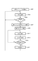
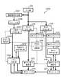
図1は、実施形態が適用する画像処理装置100の機能ブロック構成図である。以下、同図の各部を簡単に説明する。
【0014】
画像処理装置100は、イメージスキャナから画像を入力する入力部101を備えている。なお、入力部101は、ページ記述言語レンダリングなどから画像データを入力しても良いし、記憶媒体に格納された画像ファイルを読込むことで実現しても良く、場合によってはネットワークより受信するようにしても良い。
【0015】
符号化部102は、入力された画像データの符号化を行なう。なお、符号化方式は公知のJPEG符号化方式を用い、8×8画素単位に相当する画像データを直交変換し、後述する量子化ステップを用いた量子化、ハフマン符号化処理を行なうものである。
【0016】
第1のメモリ制御部103と第2のメモリ制御部105は、上記符号化部102から夫々に出力されてくる上記符号化データ(同じ符号化データ)を第1のメモリ104と第2のメモリ106へ格納する様に制御する。ここで、第1のメモリ104は、最終的に確定した(目標値以内のデータ量に圧縮し終わった)符号化データを、図1の基本構成の外部に接続されるネットワーク機器、画像出力装置や大容量記憶装置等へ出力するために、該符号化データを保持するためのメモリである。また、第2のメモリ106は、前記符号化データを第1のメモリ上に形成するための圧縮符号化処理を補助する作業用のメモリである。
【0017】
カウンタ107は、符号化部102によって圧縮符号化された画像データのデータ量をカウントし、該カウント値を保持すると共に、そのカウント結果を符号化シーケンスの制御を行なう符号化シーケンス制御部108に出力する。
【0018】
符号化シーケンス制御部108では、カウンタ107のカウント値がある設定値に達したかどうかを検出し、その設定値に達した(目標値を越えた)ことを検出した時にメモリ104内の格納済みのデータを廃棄するよう第1のメモリ制御部103に制御信号を出力する。上記第1のメモリ制御部103は、この制御信号に基づいて、メモリアドレスカウンタをクリアするか、あるいは符号化データ管理テーブルをクリアすることにより、前記格納データを廃棄する。また、このとき、符号化シーケンス制御部108は、第1のカウンタ107をゼロクリアする(入力部101からの入力は継続している)と共に、符号化部102に対して今までより、高い圧縮率で符号化を行なうよう制御する。すなわち、本装置の符号化処理で発生する符号化データのデータ量が最終的に例えば1/2になるように制御する。なお、ここでは、1/2としたが任意に設定できることは言うまでもない。
【0019】
そして、圧縮率変更後の符号化データも、これまでと同様、第1のメモリ制御部103と第2のメモリ制御部105を経て、第1のメモリ104と第2のメモリ106に夫々格納される。
【0020】
さらに、符号化シーケンス制御部108は、第2のメモリ制御部105に対して、これまでに第2のメモリ106に格納した符号化データを読み出し、符号化データ変換手段である再符号化部109に該符号化データを出力するよう制御信号を出す。
【0021】
再符号化部109は、入力された符号化データを復号化し、データ量を減らすための再量子化等を行なった後に再び符号化処理を行ない、圧縮率が変更された符号化部102と同じ圧縮率のデータ量を第2のカウンタ110に出力する。
【0022】
この再符号化部109から出力される符号化データは、第1のメモリ制御部103と第2のメモリ制御部105を経由して、それぞれ、第1のメモリ104と第2のメモリ106に格納される。
【0023】
再符号化処理が終了したかどうかは、第2のメモリ制御部が検出する。すなわち、再符号化処理するために読み出すデータが無くなれば、再符号化処理の終了を符号化シーケンス制御部108に知らせる。実際には、第2のメモリ制御部105の読みだし処理だけでなく、再符号化部109の処理も終了した後に、符号化処理が完了したことになる。
【0024】
第2のカウンタ110で得られるカウント値は、再符号化処理が完了した後、第1のカウンタ107で保持されているカウンタ値に加算される。この加算結果は再符号化処理が完了した直後における、第1のメモリ104内のデータ量の合計を表す。即ち、1画面分の符号化部102と再符号化部109の符号化処理が終了した時点では、上記加算後の第1のカウンタ107で保持されているカウンタ値は、1画面分を本装置が符号化した場合に発生した総データ量を表す(詳細は後述)。
【0025】
符号化部102は、再符号化処理の終了/未終了に関わらず、符号化するべき入力部101からの画像データが残っている限りは符号化処理を継続して行なう。
【0026】
カウンタ107のカウント値がある設定値に達したかどうかは入力部101から入力される1ページ分の画像データの符号化処理(符号化、再符号化)が終わるまで繰り返され、上述した符号化と再符号化の処理は、ここで得られる検出結果に応じた制御の上で実行される。
【0027】
上記、図1の構成における処理のフローを表わすフローチャートを図8に示すが、説明を簡単にするため、簡略化した図3のフローチャートに従って先ず説明する。
【0028】
既に説明したように、本発明の画像処理装置100は、スキャナ等の入力部101から入力した1ページの画像データを所定のデータ量以下に圧縮符号化する装置である。該符号化処理を実現するために、前記入力部101以外に、符号化部102、再符号化部109、第1のメモリ104、第2のメモリ106等を有する。これらの機能ブロックを用い、図3に示すフローチャートに基づいて符号化処理を行なう。
【0029】
図3のフローチャートは、大別すると、下記の3つの処理フェーズに分かれる。
(1)符号化フェーズ
(2)符号化・再符号化フェーズ
(3)転送フェーズ
上記それぞれの処理フェーズおいて、どのように画像データ、符号化データ等が流れて処理され,メモリにどのように格納されるかを視覚的に解り易く示したのが図4乃至図7である。
【0030】
図4は、図3のフローチャートにおけるステップS303とS305に対応する符号化フェーズの初期状態を表わす。また、図5はステップS307〜S315に対応する符号化・再符号化フェーズの処理状態を、図6はステップS317に対応する転送フェーズの処理状態を、図7は転送フェーズ後の符号化フェーズの処理状態を表わす。以下、各フェーズについて説明する。
【0031】
<<符号化フェーズ>>
1ページ分の画像データの符号化処理は、符号化パラメータの初期設定(ステップS301)から始まる。ここでは符号化処理する画像サイズ(スキャナ等の入力部101から読み取る用紙サイズ)から一意的に定まる符号化データ量の上限値や符号化部102(ここでは公知のJPEG符号化方式を用いるものとする)に適用する量子化ステップ(Q1)といったパラメータを設定する。
【0032】
そして、ステップS303にて、第1のカウンタ107は、実際の符号化処理(画像の8×8画素単位にJPEG圧縮)を行ない、出力される符号化データのデータ量を累積カウントする。
【0033】
次にステップS305にて、該データ量のカウント値が上記上限値をオーバーしたかどうかを検知し、オーバーしていなければステップS303のJPEG符号化処理を継続する。これが初期状態の符号化フェーズである。
【0034】
符号化部102から出力する符号化データは、図4に示すように第1のメモリ104と第2のメモリ106の両方に格納されていく。縦縞で示した領域が該格納した符号を表現している。
【0035】
<<符号化・再符号化フェーズ>>
符号化部102の符号化処理が進行し、前記データ量のカウント値が設定されている上限値をオーバーすると、ステップS307にて、第1のメモリ104内の符号化データを廃棄すると共に、ステップS309にて、符号化部102の量子化ステップをQ2に変更する。
【0036】
符号化データのデータ量のカウント値が設定された上限値をオーバーするという事は、圧縮後のデータ量が目標値以内に収まらないことを意味する。よって同じ量子化ステップを用いて符号化処理を継続しても意味が無いので、前よりもデータ量が少なくなるように、Q1よりも量子化ステップ幅の大きい量子化ステップQ2に変更するわけである。
【0037】
量子化ステップを変更した後、ステップS311では符号化部102の符号化処理を再開し、図5に示すように符号化データを第2のメモリ106のみに格納する。それと並行して、ステップS313の再符号化処理を行なう。再符号化処理では、第2のメモリ106に格納済みの符号化データを読み出して、再符号化部109にて再符号化処理を行ない、前記2つのメモリ104、106に格納する。そして、縦縞▲1▼の符号を全て再符号化するまで、該符号化処理と再符号化処理を継続する。再符号化部109から出力される再符号化データは、量子化ステップ変更後に符号化部102から出力される符号化データと同じ量子化ステップで符号化して得られる符号化データと全く同一の符号化データである。
【0038】
具体的にこの再符号化処理では、符号化データを一旦ハフマン復号した後の各量子化値に対して、これら値を2nで割った結果と同様の結果が出るビットシフト処理を施した後、再度ハフマン符号化を行なうことにより実現される。この方法は、ビットシフトのみで量子化ステップを変更する点と逆直交変換や再直交変換処理を行なわない点で、高速な再符号化処理が可能である。ステップ315では、再符号化処理の終了検知が行なわれる。
【0039】
再符号化後のデータ量は再符号化前の符号化データのデータ量よりも少なくなるので、図5に示すように、再符号化前の符号を格納していたメモリ領域に再符号化後の符号化データを上書きするように格納することができる。再符号化処理が終了した時点で、縦縞▲1▼の符号化データのデータ量は図6に示すの斜め縞▲1▼の符号化データのデータ量へと減少する。
【0040】
以上で説明したステップS307〜315が、符号化・再符号化フェーズで行なう処理である。
【0041】
<<転送フェーズ>>
再符号化処理が終了したら、ステップS317では転送処理が行なわれる。該転送処理では、図6に示すように、符号化・再符号化フェーズで第2のメモリ106のみに格納した斜め縞▲2▼の符号化データを、第1のメモリ104内の斜め線▲1▼の符号化データに連結されるアドレスに転送し、格納する。その一方で、第2のメモリ106上で分散してしまっている斜め縞▲1▼の符号化データと斜め縞▲2▼の符号化データが第1のメモリ104上で連続して格納される様に、前記斜め縞▲2▼の符号化データを第2のメモリ106内で転送し、連結させる。これが、転送フェーズで行なう処理である。
【0042】
上記転送フェーズが終了したら、ステップS303、S305の符号化フェーズに戻り、図7に示すように斜め縞▲4▼の符号を符号化部102から出力して2つのメモリ104,106に格納する。この符号化フェーズは、初期状態の符号化フェーズ(図4)と少し異なり、符号化部102で符号化する際の量子化ステップがQ1からQ2に変更されていると共に、2つのメモリ104,106に格納されている符号化データも様々なフェーズで処理された符号の集まりである。それらの違いを無視すれば、転送フェーズ直後の符号化フェーズと初期状態の符号化フェーズは、同じと見なせる。
【0043】
よって、符号化フェーズ、符号化・再符号化フェーズと転送フェーズの3つを繰り返すことで、最終的に1ページの画像データをデータ量設定値以下に圧縮した符号を第1のメモリに格納することが出来る。しかも、入力部101は一連の処理が終わるまで、入力を継続するだけである。すなわち、画像を再度最初から入力し直すということが無くなる。
【0044】
図3に示したフローチャートは、説明が理解しやすいように、図4、図5、及び、図6に示した各フェーズに対応する処理のみを記述した。しかしながら実際には、1ページの画像データの入力はどこかのフェーズで終了する。従って、どのフェーズで終了したかによって、それ以降の対応も多少異なる。それを考慮した流れを示したのが図8のフローチャートである。図8のフローチャートは、1ページ分の画像データの入力完了と図3で説明した各種処理との関係を考慮したものであり、ここでは図3のフローチャートに、ステップS801、S803、S805、S807を追加している。
【0045】
ステップS801、S803、S805は、それぞれ、符号化フェーズ、符号化・再符号化フェーズ、転送フェーズにおいて、入力部101からの1ページ分の画像データの入力が終了したことを検知する。
【0046】
符号化フェーズと転送フェーズで1ページ分の画像データの入力が終了したことを検知した場合(ステップS801、S805)、ステップS807へ移り、当該ページの圧縮符号化処理を終了し、次に処理すべき1ページ以上の画像データがあれば、次の1ページ分の画像データの圧縮符号化処理を開始し、無ければ停止状態に入る。
【0047】
一方、符号化・再符号化フェーズで1ページ分の画像データの入力終了を検知した場合(ステップS803)には、符号化部102では再符号化処理する画像データが無くなるまで一旦動作を止める必要があるので、ステップS311の符号化処理をパスし、ステップS313で、今までに符号化部102で符号化済みの画像データを所定の符号化データ量に抑える為の再符号化処理のみを継続して行なう。再符号化処理が全て終了して、その後の転送処理が終わらないと、1ページ分の画像データ全体の符号化データが第1のメモリ上に集まらないため、1ページ分の画像データの入力終了後も再符号化処理及びそれに続く転送処理は継続して行われる必要がある。この場合には、ステップS315にて、再符号化処理が全て終了したことを検知すると、符号化・再符号化フェーズ中に、第2のメモリ106のみに格納された符号化データを第1のメモリに転送し(ステップS317)た後、次のステップS805にて、1ページ分の画像データの入力終了が検知されてステップS807へ移ることになる。
【0048】
以上が動作であり、図8の動作説明でもある。
【0049】
<メモリ格納方法の変形例>
図9、図10は図5、図6の概念図で示したメモリ格納方法の変形例を示す図である。
【0050】
図5の概念図においては、符号化・再符号化フェーズでは、符号化部102から出力する符号化データは第2のメモリ106のみに格納していたが、図9に示すように符号化・再符号化フェーズ中に、符号化部102から出力する符号化データを第1、第2メモリの両方に直接格納する。
【0051】
符号化部102から見ると、どのフェーズで符号化して出力する符号化データも両方のメモリへ格納することになる。また、図6の概念図とは異なり、図10に示す様に、転送フェーズでメモリ間のデータ転送が必要なくなる。またこの変形例の場合には、符号化・再符号化フェーズにおいて、符号化データと再符号化データを第1のメモリ104へ送った順序で順次格納される。そのため2種類のデータが入り混じってしまうという問題は有る。
【0052】
従って、この変形例の場合にはこれに対応する為に符号化データをある単位で区切って、ファイル或いはパケットとして管理する様にする。具体的には、ファイル管理テーブル、或いは、パケット管理テーブル等を別に作成して管理する。
【0053】
一つの手法としては、符号化部102からのデータを第1メモリ104に格納する際、適当な単位(例えば前記直交変換の単位が8×8のブロックであるので、8×i(i=1、2…の整数)ライン分のデータ)毎に、画像データの先頭から管理番号を割り当て、各管理番号に対応する符号化データの格納先頭アドレスと該符号化データ量とを、管理番号順に格納できるような管理テーブルを作成する。
【0054】
符号化部102や再符号化部109は処理中のデータの管理番号を保持し、該管理番号に基づいて、符号化データ格納時の先頭アドレスと符号化データ量とを管理テーブルに書き込む。このようにすれば、符号化部102と再符号化部109で処理した符号化データをランダムに格納したとしても、前記管理テーブルを管理番号順にアクセスし、その時読み出させる先頭アドレスと符号化データ量に基づいて、符号化データを第1メモリ104から読み出せば、画像の先頭から順番に符号化データを読み出すことができる。このような管理機構を設ければ、画像上で連続するデータをメモリ上で連続するように格納する必要性が無くなる。
【0055】
図10の概念図における転送フェーズ後の符号化フェーズは、これまで説明した2つの符号化フェーズ(図4、図7)とほとんど同じであり、第1のメモリ内における符号の格納状態が図11に示した様に若干異なるだけである。よって、先の説明と本変形例は、3つのフェーズを繰り返して処理することに変わりは無い。
【0056】
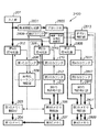
次に、本発明において特徴的な符号化処理を行なう為の、第2の基本構成の例(これまで説明した構成を第1の例という)を図2を用いて説明する。
【0057】
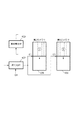
図2は、第2の例における画像処理装置200のブロック構成図である。
【0058】
図1の画像処理装置100と大きく異なる点は、最初に符号化を行なう符号化部が2つ並列に存在する点である。画像処理装置200は、入力部201から入力される画像データを、第1の符号化部202と第2の符号化部205で並行して符号化し、互いに圧縮率の異なる2種類の符号化データを生成する。本例でも、符号化方式は公知のJPEG符号化方式を用い、8×8画素単位に相当する画像データを直交変換し、後述する量子化ステップを用いた量子化、ハフマン符号化処理を行なうものである。
【0059】
なお、本例では第1の符号化部202よりも、第2の符号化部205の方が適用する圧縮率を高く設定する場合について説明する。具体的には、第1の符号化部202における量子化ステップをQ1、第2の符号化部205の量子化ステップをQ2(=2×Q1)とする。
【0060】
符号化部202から出力される符号化データは、第1のメモリ制御部203を経由して、第1のメモリ204に格納される。このとき、第1のカウンタ208は、符号化部202から出力される符号化データのデータ量をカウントし、これを保持すると共に、符号化シーケンス制御部209にも出力する。
【0061】
一方、符号化部205で符号化された符号化データは、第2のメモリ制御部206を経由して、第2のメモリ207に格納される。このとき、第2のカウンタ210は、符号化部205から出力される符号化データのデータ量をカウントし、これを保持する。更に、後述する第2のメモリ207に格納している符号化データを第1のメモリ204に転送する時には、それと同時に上記カウント値を、第1のカウンタ208に転送する。
【0062】
さて、第1のカウンタ208が符号化部202から出力される符号化データのデータ量をカウント中に、該カウント値がある設定値に達した時には、符号化シーケンス制御部209は、第1の例と同様、メモリ制御部203に対してメモリ204に格納されているデータを廃棄するよう制御信号を出す。
【0063】
そして、符号化シーケンス制御部209は、第2のメモリ207に格納している符号化データを読み出して第1のメモリ204に転送し、第1のメモリ204に格納するよう、メモリ制御部206とメモリ制御部203に制御信号を出力する。この結果、第2のカウンタ210のカウント値が第1のカウンタ208に転送され、その値が第1のカウンタのカウント値としてロード(上書き)される。
【0064】
要するに、上記第2のカウンタ210のカウント値は、第2のメモリ207に格納している符号化データのデータ量を表わしているので、そのカウント値と符号化データを、互いの対応付けが変わらない様に、そのまま第1のカウンタと第1のメモリへコピーしたと考えれば良い。
【0065】
さらに、符号化シーケンス制御209は、第1の符号化部202および、第2の符号化部205に対して、今までよりも、符号化データが少なくなるような符号化を行なうように制御信号を出す。
【0066】
例えば、第1の符号化部202、及び、第2の符号化部205における量子化ステップSを2倍に切り替えす。この結果、第1の符号化部202は、その直前までの第2の符号化部205における量子化ステップQ2(=2×Q1)を継承することになり、第2の符号化部205は更に大きな量子化ステップQ2×2を用いて、次のオーバーフローに備えた更に高い圧縮率の符号化処理を行うことになる。
【0067】
ここでは、量子化ステップの倍率比を2倍としたがこれに限らず、任意に設定できることは示すまでもない。切り替えられた各符号化部202、205から出力された符号化データは、それぞれ、対応するメモリ制御部203、206を経由して、対応するメモリ204、207に格納される。
【0068】
そして、符号化シーケンス制御209は、メモリ制御部206に対し、既に第2のメモリ内に格納している符号化データを読み出して、再符号化部211にデータを送るよう制御信号を出す。再符号化部211は、図1の再符号化部109と同様にして符号化データの再符号化処理を行なう。
【0069】
第3のカウンタ212は、再符号化部211が出力したデータ量をカウントするもので、再符号化処理を開始する直前にゼロにリセットされ、再符号化処理中の出力データ量をカウントする。このカウンタ212は、再符号化処理が終了した時点で、そこで得られたカウント値を第2のカウンタ210に転送する。
【0070】
第2のカウンタ210は、上記転送されてきたデータ量カウント値を、第2のカウンタ210内に保持しているカウンタ値に加算することにより、再符号化処理中にメモリ207に格納した、符号化データと再符号化データの合計のデータ量を算出する。即ち、メモリ207に格納しているデータ量とカウンタ210のカウント値とが一致する。
【0071】
再符号化処理の終了/未終了に関わらず、符号化するべき入力部201からの画像データが残っていれば、2つの符号化部202と205による符号化処理を継続して行なう。そして、カウンタ208のカウント値がある設定値に達したかどうかの監視は入力部201から入力される1ページ分の画像データの符号化処理(符号化、再符号化)が終わるまで繰り返され、上述した符号化と再符号化の処理は、ここで得られる検出結果に応じた制御の上で実行される。
【0072】
上記図2の構成における処理のフローを表わすフローチャートを図12に示す。
【0073】
図2で説明したように符号化部が2つある場合は、図12に示すフローチャートに基づいて1ページ分の画像データの符号化を行なう。なお、図12の説明は、符号化部が1つの場合のフローチャートである図8とは、大半は類似しており、当業者であれば上記説明から本第2の例の特徴は十分に理解できるであろうから、符号化部1つの場合と同じように3つのフェーズで処理を説明する様にし、図8と異なる点を主に説明することとする。
【0074】
上述した図8のフローと本例のフローとの一番大きな違いは、ステップS317の転送処理が、ステップS307とステップS309の間に移動していることである。要するに、符号化・再符号化フェーズと転送フェーズが入れ替わったと見なせば良い(ステップS307の符号化データの廃棄処理は例外である)。
【0075】
ステップS301の符号化パラメータの初期設定では、第1の符号化部202に量子化ステップQ1を、第2の符号化部205には量子化ステップQ2(=2×Q1)を設定する。
【0076】
符号化フェーズでは、ステップS801、S303、S305を繰り返し実行する。ステップS801とステップS305は符号化部が1つの場合と同じ処理であるが、ステップS303の符号化処理だけは図13に示すように異なっている。
【0077】
第1のメモリ204へ格納する符号化データは圧縮率が段階的に高くなるようにするため、最初に格納する符号化データは圧縮率が一番低い量子化ステップQ1で符号化したデータを格納し、第2のメモリへ格納する符号化データは量子化ステップQ2で符号化したデータを格納する。
【0078】
第1のメモリ204へ格納中のデータ量が設定されている上限値をオーバーしたら(ステップS305)、直ちに、第1のメモリ204で保持していた符号化データを廃棄し(ステップS307)、第2のメモリ207で保持している圧縮率の高い符号化データを、第1のメモリ204へ転送する(ステップS317、図14参照)。これにより、第1の例(図1)で説明した1回目の再符号化処理の終了を待たずに、速やかに、上限値をオーバーしない適切な2番目の候補の符号化データを第1のメモリ207内に格納出来る。これが、図1に対する、2つの符号器を持つ図2を適用することの最大の利点である。
【0079】
本第2の例では、2つのメモリ204、207で同じ圧縮率の符号化データを持っていることが無駄という考え方なので、第2のメモリ207には、第1のメモリ204に格納する符号化データよりも圧縮率の高い符号化データを格納しておくようにしている。従って、それ以降の処理もこの考え方に基づき行われるものであり、第2のメモリ207内の符号化データを第1のメモリ204に転送する処理(転送フェーズ)が終了した後は、第2のメモリ207の符号化データを、更に1段階圧縮率の高い符号化データを保持する様に再符号化することとなる。
【0080】
具体的には、まず図15に示す様に、転送フェーズの次の符号化・再符号化フェーズでは、上記再符号化の前に、2つの符号化部202,205に適用される各量子化ステップQ1、Q2をそれぞれQ2、Q3へ変更し(ステップS309)、1ページの画像データの入力が終了せずに続いていれば(ステップS803)、後続の画像データは新たな量子化ステップが設定された2つの符号化部で該入力データを符号化して(ステップS311)、対応する各メモリ204,207へ格納する。そして、上記符号化処理と並行して第2のメモリに格納されている符号化データ(第1のメモリ204に転送したもの)は、第1のメモリ内の符号化データよりも1段階高い圧縮率の符号化データに変更するべく、再符号化部211にて量子化ステップQ3を用いて符号化されたデータが得られる様な再符号化処理(S313)を行ない、再符号化データを第2のメモリ207に格納し直す。
【0081】
なお、本第2の例でも、第1の例と同様、再符号化処理では、符号化データを一旦ハフマン復号した後の各量子化値に対して、これら値を2nで割った結果と同様の結果が出るビットシフト処理を施した後、再度ハフマン符号化を行なうことにより実現される。この方法は、ビットシフトのみで量子化ステップを変更する点と逆直交変換や再直交変換処理を行わない点で、高速な再符号化処理が可能である。
【0082】
なお、本第2の例の様に符号化部が2つ有る場合には、図15に示したように、第2のメモリ207に符号化データと再符号化データを混在して格納する状況が発生する。従って、前述したように、符号化データをある単位で区切って、ファイル或いはパケットとして管理することが、第2のメモリ207に対しても必要になる。その為には、例えば第1の例における変形例と同様の構成を設ければ良いであろう。
【0083】
図12において、再符号化処理の終了をステップS315で検知したら、また符号化フェーズ(ステップS801、S303)に移行する。なお、符号化・再符号化フェーズ後の符号化フェーズでは、図16に示すように、2つのメモリ204,207が保持する符号化データは圧縮率が違うだけでなく、符号化データの混在の仕方(アドレス)もかなり違ってくる。従って、再度、第1のメモリ204のデータ量が設定値をオーバーした場合には、第2のメモリ207で保持されている符号化データ(▲6▼+▲8▼の横縞の領域の符号)が第1のメモリ204へ転送される必要が出てくる。これらを考慮すると、第2のメモリ207だけでなく、第1のメモリ204でも符号化データをファイル或いはパケットとして管理する必要がある。よって、第1のメモリ204にも前述の管理テーブルを用いた管理機構が必要となる。
【0084】
図16に示された符号化フェーズの状態は、量子化ステップと符号化データの混在の仕方が、再符号化処理の前後で異なっていること以外は、初期状態の符号化フェーズ(図13)と同じである。よって、符号化フェーズ、転送フェーズと符号化・再符号化フェーズを繰り返すことで、最終的に、1ページ分の画像データを設定した上限値以下に圧縮した符号化データを確実に第1のメモリ204に格納することが出来る。
【0085】
なお、第1の例の説明とは、転送フェーズと符号化・再符号化フェーズの配置順が逆であることから、図8において転送処理後に行なっていた1ページ分の画像データの入力終了検知(ステップS805)は、符号化・再符号化フェーズで行なう1ページ分の画像データの入力終了検知(ステップS803)と、ほとんど同じタイミングになってしまう。また、2つの検知処理は、機能的にはステップS805と同じで、タイミング的にはステップS803と同じである、従って、これら2つのステップは、新たな1ページ分の画像データの入力終了を検知するステップとして統合し、ステップS1201と表記しておく。
【0086】
以上説明した第1、第2の例では、第1のメモリと第2のメモリは物理的に別のメモリであるとして説明をしてきた。これは、2つのメモリに対するアクセスが独立したものとすることができるので有利なためであり、本発明の特徴となす。しかしながら、第1のメモリと第2のメモリを、物理的に別のメモリとしない場合も本発明の範疇に含まれる。物理的に1つのメモリ上に、前記第1のメモリと第2のメモリに相当する2つの領域を確保して、第1のメモリを第1のメモリ領域、第2のメモリを第2のメモリ領域と言い直して、これまでの説明を読み直せば、本発明は、1つのメモリでも実現できることが分かる。
【0087】
また、1つのメモリで上記各例を実現する場合には、前記転送フェーズで説明したデータ転送処理のいくつかは不要となる。その詳細はその都度容易に想像できるので説明は省略するが、前記2つの領域を厳密に別けて使用する場合、物理的に2つのメモリを持つ時と同じようにデータ転送処理が必要であるが、2つの領域間で同じデータを共有することになれば、データ転送処理が不要になるだけでなく記憶容量の削減も図れる。
【0088】
例えば、第2のメモリ領域で保持していた符号化データを、第1のメモリ領域へ転送する際、該符号化データが格納されている先頭アドレスとデータサイズの2つの情報を第2のメモリ制御部から第1のメモリ制御部へ転送するだけで、前記符号化データを転送したのと同じ効果が得られる。
【0089】
前記符号化データを、ファイル形式やパケット形式で格納している場合は、メモリ制御部の間で転送する情報は少し増え、該符号化データに関連する管理テーブル情報を転送する必要がある。それでも、符号化データを転送するよりは、効率が良い。
【0090】
さて、上述した画像処理装置によると、入力した画像データを符号化していく際に、目的とするサイズに越えるような場合であっても、その入力を継続しつつ目標とするサイズに収めるよう処理を継続することができるようになるが、本発明では、上記画像データの圧縮データの符号量の制御以外に、該画像データに付随する像域情報を符号化したデータの符号量の制御も行なうものである。
【0091】
以下に説明する実施形態では、像域情報の符号化処理と符号化データの符号量の制御をどのように行なうかを説明する。
【0092】
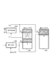
<第1の実施形態>
上述の画像処理装置に本発明を適用した第1の実施形態を図17に示す。同図は図1に示した基本構成に本発明を適用したもので、図1の構成と同じ機能ブロックには、同一番号を付すことで、その説明は省略する。
【0093】
イメージスキャナやページ記述言語レンダリングなどから入力部101を通して入力した画像データは、既に説明した処理方法に基づいて符号化と再符号化処理を繰り返して行ない、符号化データを設定した符号量以内に収める。
【0094】
一方で、画像データは像域情報生成部1701に供給され、前述の像域情報を生成する。本実施形態では、スキャナ入力画像について説明しているので、画像データのみに基づいて像域情報を生成するが、ページ記述言語(PDL)を展開・描画した画像の場合、該PDL情報も参照して像域情報を生成すれば良い。なお、像域情報はスキャナ等の画像入力機器で生成することもある。その場合、前記像域情報も入力部101を通して入力され、像域情報生成部1701を素通りして、次のユニットへ送られる。
【0095】
さて、像域情報生成部1701で生成する像域情報であるが、実施形態では、着目画素が文字・線画領域であるか中間調領域であるのか、及び、有彩色か無彩色なのかを示す情報を生成する。それぞれ1ビットで表現できるので、1画素について合計2ビットの像域情報(それぞれのビットは、像域情報を構成することになるので像域成分情報という)を生成することになる。
【0096】
像域情報生成部1701の動作を簡単に説明すると、次の通りである。
【0097】
先ず、文字・線画領域か中間調領域であるのかの判断であるが、文字・線画のの場合には背景に対してその輝度(或いは濃度)が急峻に変化する。一方、中間調領域にある場合、注目画素の輝度(或いは濃度)は隣接する画素に対して変化が小さい。従って、注目画素の輝度をLi、左右の画素の輝度をLi-1、Li+1と定義したとき、
|Li−Li-1|>T
又は、
|Li−Li+1|>T
である場合に、注目画素は文字線画(のエッジ)にあると判断できる。尚、ここでの|x|はxの絶対値を示すものである。
【0098】
なお、濃度が急峻に変化しているか否かを判断する式は上記のものに限らない。例えば、
|2Li−Li-1−Li+1|>T
を満たすかどうかで判断してもよいし、一次元方向のみではなく、2次元方向について判断するようにしても良い(但し、2次元で判断する場合には、像域情報生成部1701内には、複数ライン分の画像データを記憶するためのメモリを必要とする)。
【0099】
一方、有彩色/無彩色の判断であるが、入力される画像データはスキャナより読み取られたものであるので、R、G、Bのデータ形式になっている。
【0100】
無彩色というのは、RGBの各色成分が互いに同じ輝度である場合であるので、
R=G=B
なる関係を有する場合には無彩色として判断し、それを満たさない場合には有彩色と判断する。ただし、スキャナ装置が有するCCDの精度も加味する必要があるので、実際は、
B−Δ<R<B+Δ
R−Δ<G<R+Δ
G−Δ<B<G+Δ
の全てを満たすとき無彩色と判断し(Δは適当な小さい数値)、それ以外を有彩色と判断するようにしても良い。
【0101】
場合によっては、RGB色空間を例えば輝度、色相、彩度(例えばLab表色空間)に変換し、その彩度が所定値以下の場合に無彩色、所定値を越える場合に有彩色と判断しても良いであろう。
【0102】
以上の如く、像域情報生成部1701は、入力された画像データから注目画素が文字・線画/中間調領域か、有彩色か無彩色かを示す2ビットの像域情報を生成し、出力する。
【0103】
図17の説明に戻る。上記のようにして、生成した像域情報は、ブロック化ユニット1703にて、まとめて符号化するデータのサイズ、例えばM×Nのサイズ(従ってM×N×2ビット)へブロック化する。ブロックサイズは、32×32とするが、符号化効率を上げるため、それ以上、例えば64×64や128×128でも構わないし、必ずしも正方サイズである必要もない。それ故、M×Nサイズとした。
【0104】
ところで、像域情報を符号化する場合、通常の画像データの圧縮に利用するJPEGのような多値の非可逆圧縮は適さない。それ故、可逆圧縮であるJBIG、或いはPackBits等のランレングス符号化を用いることとした。可逆符号化部1705では、該当するブロックの像域情報を、この可逆符号化する。
【0105】
符号化した像域情報は、第3のメモリ制御部1707を経由して、第3のメモリ1709に格納する。また、これと同時に、前記可逆符号化部1705から出力する符号量を第4のカウンタ1711が累積カウントしており(1ページの読み取りを開始する際にリセットされる)、その結果を符号化制御部1713に供給している。
【0106】
符号化制御部1713には、不図示のレジスタが設けられ、このレジスタに像域情報の目標符号量が予め設定されいる。そして、符号化制御部1713は、第4のカウンタ1711で計数されている符号量が、この目標値をオーバーしたか否かを監視していている。そして、目標値をオーバーしたと判断した場合、符号化制御部1713は、可逆符号化部1705及び可逆符号再符号化部1707にそれぞれに対して以下に示す指令を発すると共に、第4カウンタ1711をリセットする。
【0107】
先ず、可逆符号再符号部1707に対しては、第3のメモリ1709から符号化した像域データを読み出し再符号化するよう指令を発する。この結果、可逆符号再符号化部1715は、第3のメモリ1709から符号化されたブロック単位の像域情報を読出し、それを一旦復号し、ランレングスを高める処理を行い、再度符号化して、第3のメモリ1709に格納する。
【0108】
このランレングスを高める処理であるが、次の2通りを用意した。
処理P1:文字・線画/中間調画素の識別ビットが中間調画素を示している画素位置の、有彩色/無彩色の識別情報を全て有彩色に変更する。
処理P2:文字・線画/中間調画素の識別ビットを中間調画素を示すように変更する。
【0109】
符号化制御部1713は、或るページの像域情報を符号化している最中に、最初に目標値をオーバーすると判断した場合には、上記の処理P1を採用する。そして、この処理を行っても、目標値をオーバーすると判断した場合(2回目にオーバすると判断した場合)には、処理P2を用いて再度符号するようにした。
【0110】
有彩色/無彩色の識別情報を有彩色にするのは、色空間において有彩色空間が無彩色を含んでいるため、大きな問題にはならないからである。また、文字・線画/中間調の識別情報を中間調にすることも、同様の理由による。
【0111】
いずれにしても、かかる像域情報を変更することで、そのエントロピーが低下するため、ランレングス符号化後のデータ量は減少する。再符号化後の属性データは、メモリ1709に再び格納すると共に、その符号量を第5のカウンタ1717にてカウントする。そして、可逆符号再符号化部1715は、可逆符号化部1705によって既に符号化した全符号についてこの処理を行っていく。こうして、符号化制御部1713から指令があった時点で、第3のメモリ1709に格納されていた符号データ(可逆符号化部1705で符号化されたデータ)に対する再符号化及び格納を行う。このときの符号量は、第5のカウンタ1715で計数しており、その計数結果が第4のカウンタに加算される。
【0112】
一方、可逆符号化部1705は、符号化符号化制御部1713から目標値をオーバーした場合に発した命令に従い、注目ブロック以降について、上記の可逆符号再符号化部1715と同じ処理を開始する。すなわち、或るページの符号化を行って最初にオーバーすると判断された場合には、先に示した処理P1でもってブロック化部1703からのブロックについてランレングスを高める処理を行い、その結果を符号化して第3のメモリ1709に格納する。この間、可逆符号化部1705で符号化された符号量は、第4カウンタ(オーバーすると判断された時点でリセットされる)で計数回数を開始するが、先に説明したように、可逆符号再符号化部1715でも再符号化が行われた際の、符号量(第5のカウンタ1717)と加算されることになるので、結果的に、1ページについての属性情報について、処理P1で行った結果と同様の符号量を第4カウンタ1711が計数することになる。
【0113】
こうして、処理P1に切り換わって像域情報の符号が行われている最中に、再度目標値をオーバーすると判断した場合、符号化制御部1713は、第4カウンタ1711をリセットすると共に、可逆符号化部1705及び可逆符号再符号化部1715に対して、先に示した処理P2に切り換わるよう指令を発する。
【0114】
以上をまとめると、次のようになる。
【0115】
符号化制御部1713は、可逆符号化部1705における像域情報の符号化量を監視していて、その符号量が目標値をオーバーすると判断した場合、可逆符号化部1705及び可逆符号再符号化部1715に対して処理P1で行うように設定し、第4カウンタ1711をリセットする。第4カウンタ1711は、これ以降、可逆符号化部1705による符号量及び第5カウンタ1717のカウント値を加算していく。従って、可逆符号再符号化部1715による再符号化が完了した時点では、1つの画像(或いは1ページの画像)について最初から処理P1で行ったときと実質的に同じ符号量を計数することとなる。また、第3のメモリ1709には処理P1での符号化データが格納されることになる。
【0116】
この処理P1による処理中に、再度、目標値をオーバーすると判断した場合、今度は、可逆符号化部1705及び可逆符号再符号化部1715に対して処理P2で行うように設定し、第4カウンタ1711及び第5カウンタ1717をリセットするようにする。
【0117】
以上の結果、入力部101からの画像データの入力を継続しつつ、目標値(目標サイズ)以内に像域情報を可逆符号化させることができるようになる。
【0118】
次に、本第1の実施形態の処理内容を表わすフローチャートを図18に示し、該フローチャートを用いて説明を行なう。本実施形態の処理は、上述したように、大きく2つの処理に分かれる。1つは可逆符号化処理、もう1つは再符号化処理である。
【0119】
符号化処理は、ステップS1805の像域情報変換処理とステップS1807の可逆符号化処理とからなり、再符号化処理は、ステップS1815の復号化処理と、ステップS1817の像域情報変換処理、それにステップS1819の再符号化処理とからなる。
【0120】
その他のステップは、S1813の像域情報変更処理の変更を除くと、条件分岐と開始及び終了ステップである。
【0121】
まず、ステップS1801から、像域情報の符号化処理を開始する。次のステップS1803で、画像1ページに対する像域情報の入力が全て終了しているかどうかを検知し、終了していればステップS1821へ行き、終了していない場合、すなわち、像域情報の入力がある場合には、ステップS1805の像域情報変換処理を行なう。
【0122】
再符号化処理がまだ一度も起動していない初期状態では、像域変換処理では何も処理せず、入力された像域情報をそのまま次のステップS1807の可逆符号化処理で符号化する。
【0123】
次のステップS1809では、再符号化処理中であるかどうかを判定し、再符号化処理中であれば、前記ステップS1815〜S1819から成る再符号化処理を行なうが、再符号化処理中でなければ、ステップS1811へ行き、符号化したデータ(符号量)が設定値をオーバーしたかどうかを判定する。
【0124】
オーバーしていなければ、ステップS1803に戻り、符号化処理を繰り返し、オーバーしていれば、像域情報変換処理における処理内容を変更する。該変更により、ステップS1805、S1817における像域変換処理の内容が変わる。具体的には、初期状態では、処理P1、すなわち、入力された像域情報中の、文字・線画/中間調の識別情報が中間調であると判断された画素位置の、有彩色/無彩色の識別情報を全て有彩色とする。
【0125】
この像域情報変換処理内容の変更後は、再符号化処理を行なう。再符号化処理では、ステップS1815にて、符号化した像域情報を復号化処理して符号化前のデータに戻す。次のステップS1817にて、前記像域情報変換処理を行ない、上記像域情報変更処理を行い、次のステップS1819にて、変換した像域情報を再び可逆符号化する。
【0126】
上記再符号化処理が終わったら、ステップS1803に戻り、像域情報の入力があれば、それを符号化処理する。符号量が一度でも設定値をオーバーすると、像域情報変換処理内容が変更され、ステップS1805の像域情報変換処理にて、処理P1に置き換えられた後に、ステップS1807にて、可逆符号化される。
【0127】
こうして、処理P1に置き換わった後に、再び、ステップS1811で符号量が目標値をオーバーしたと判断した場合には、ステップS1813で、ステップS1805及びS1817における像域変更を処理P2に変更するように設定する。
【0128】
いずれにしても、像域情報の入力が全て終了し、且つ、再符号化処理もしていなければ、ステップS1823へ移り、像域情報の符号化処理を終了する。
【0129】
以上説明したように、本第1の実施形態によれば、1つ、或いは1ページの画像データの入力を中断したり、再入力することなく、目標サイズ以内に画像データを符号化させると共に、その画像の像域情報についても目標サイズ以内に可逆符号化させることができるようになる。
【0130】
実施形態における可逆符号化部及び可逆符号再符号化部がpackbits符号化を採用した場合の例を以下に説明する。
【0131】
ここでは、1画素あたり2ビットの像域情報に、6ビットデータ“000000”を付加して8ビット化した後、可逆符号としてPackbits符号化を行なった場合の、本実施形態における具体的な処理内容を図19を用いて説明する。
【0132】
Packbits符号化する前の8ビットデータは、図19(a)に示すように上位6ビットは全て0で、下位2ビットの上位側に、対応する画素データが文字・線画/中間調を識別するためのフラグ、下位側には有彩色/無彩色を表わすフラグが格納されているものとする。よって、該8ビットデータが取り得る値は、0以上3以下の値である。また、説明を簡単にするため、像域情報生成部1701からは1次元の像域情報が出力されるものとして説明する。
【0133】
像域情報生成部1701からは、上記8ビットのデータが画素単位で出力される。具体的な出力データとして、図19(b)に示すデータを考える。
【0134】
これをPackbits符号化すると図19(c)に示すデータに圧縮される。圧縮後のデータで負の値は連続するデータの個数を表わし、非連続データの個数は正の値で表わしている。これらは長さ情報と言うもので、該長さ情報のサインビットから連続データが続くのか、非連続データが続くのかを判別することが出来るようになっている。圧縮後の各データは(b)と同じく8ビット(1バイト)である。1バイトの長さ情報で、表わすことができる最大値は255の半分の約128であり、長さ情報がそれ以下の場合は1組の長さ情報とそれに続く像域フラグデータ群で符号化でき、それを超える場合は複数の組の、長さ情報+像域フラグデータ群、に分けて符号化される。
【0135】
図19(c)の圧縮データを詳しく見てみることにする。最初の長さ情報「−4」はマイナスの値なので、上述したように連続データの連続個数を表わし、長さ情報直後の像域フラグデータ「1」が4つ続くことを表わしている。
【0136】
次のデータ「4」はまた長さ情報であるが、今度はプラスの値なので非連続データが4つ続くことを示している。よって、前記「4」に続く4つのデータ「2,3,2,3」が非連続データを表わす。図19(c)では、長さ情報と像域フラグデータとが区別し易いように、プラスの長さ情報のみ下線を引いている。
【0137】
上記非連続データの次の「−5」は又、連続データの長さ情報で、該長さ情報直後の像域フラグデータ「2」が5つ続くことを表わしている。次の下線付きのデータ「3」は非連続データの長さ情報で、後続する3つのデータ「1,0,1」が像域フラグデータであり、さらに次の「−6,0」は、データ「0」が6個連続することを示している。
【0138】
上記圧縮データを可逆符号再符号化部1715で再符号化処理するとどのようになるのかを、図19(d)(e)を用いて説明する。ここで説明を簡単にするため、再符号化処理において、有彩色・無彩色フラグのビットを「1」に固定することで、すべて有彩色にしてしまう場合について説明する。
【0139】
符号化された像域データは一旦復号され、図19(b)のデータに戻された後、上記フラグデータの置き換えが行なわれることで、図19(d)のデータに変換される。これを再び、Packbits符号化すると、同図(e)の符号化データが得られる。再符号化前は15バイトの符号化データであったのに対し、再符号化後には6バイトにまで減少することが解かる。
【0140】
上記の再符号化処理を行なったにもかかわらず、全符号量の計数値が符号化制御部1713内のレジスタに設定された目標値を再びオーバーした場合には、前記再符号化処理が終了していれば、直ちに次の新たな再符号化処理を開始する。前記再符号化処理が終了していなければ、該再符号化処理が終了後、直ちに次の新たな再符号化処理を開始する。
【0141】
新たな再符号化処理では、残りの1ビットの像域フラグも“1”に置き換える。これにより、すべての像域フラグデータ(8ビット)の値は“3”となり、データのバイト数をNとすると、符号化後のデータ量はおよそ(2N/128)+2バイトとなる。
【0142】
これは、連続データの個数が128個を超えるたびに、あらたな2バイト1組の符号化データ(長さ情報と連続データ)が増えるためである。
【0143】
Packbitsの符号化回路や復号回路それにデータ変換回路はそれぞれ公知の技術であるため、個別の回路構成についての説明は省略する。
【0144】
なお、上記実施形態では、説明では簡単化のため、各画素の像域フラグを2ビットとして説明したが、前述したように像域フラグとして他の情報を付加させるようにしてもよい。
【0145】
理論上、像域情報を変換する処理は、像域の種別としてNビットであれば2N個存在することになる。但し、変換する毎に、圧縮率が高くなる必要がある。いずれにしても、像域情報のビット数が多ければ多いほど再符号化処理の回数を増やすことができ、符号量を多段階で制御することができる。
【0146】
上述したように像域情報データの可逆符号化処理は、画像データの圧縮符号化処理とは独立に制御され、それぞれに目標符号量以内のデータに収められる。
【0147】
符号化された2種類のデータは、外部に接続されるネットワーク機器、画像出力装置や大容量記憶装置等へ出力する際に多重化する。該多重化を考慮して、前記2種類のデータを符号化処理する単位を同じサイズに合わせておき、1単位を符号化して生成される符号化データを1つのパケットあるいはファイルとして管理・格納する。多重化する際に、画像位置が同じ2種類のパケットデータを、例えば画像データ・像域データの順に連結して、1パケット化し、外部へ出力する。
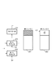
【0148】
前記2つの符号化処理は独立に制御されるので、画像データの圧縮符号化処理部が他の構成であっても構わない。よって、像域情報データを可逆符号化処理するユニット1701〜1717を前記図2の構成に対して付加しても、同じように処理することが可能である。その構成を図20に示しておくが、ユニット1701〜1717の動作は図17とまったく同じであり、画像データ圧縮部分の動作も図2の動作とまったく同じである。
【0149】
<第1の実施形態の変形例>
上記実施形態では、像域成分情報の2ビットは、一方が文字・線画/中間調の識別ビット、他方が有彩色/無彩色のビットとし、それらを1つの値として0〜3の値を持つものとして扱った。しかしながら、文字・線画/中間調の識別情報と、有彩色/無彩色の識別情報は、本来は独立した情報である。そこで、文字・線画/中間調の識別ビットで構成されるブロックと、有彩色/無彩色の識別ビットで構成されるブロックを独立させ、それぞれ独立して符号化するようにしても良いであろう。この結果、それぞれのブロック内の各ビットは同じ種類のビットのみで構成されることになり、最初の段階で圧縮効率を高くできるようになり、その結果、像域情報の一部のビットを固定値に変換する確率を低くして、原像域情報のまま圧縮符号化できる確率を高くできる。
【0150】
<第2の実施形態>
第2の実施形態では、像域情報のビット数が前記第1の実施形態と同じでも、再符号化処理の回数を増やせて、符号量を細かく制御することが出来る処理方法について説明する。本実施形態の構成も前記第1の実施形態と同じであり、違うのは、可逆符号化部1705と可逆符号再符号化部1715における像域フラグデータの圧縮方法である。
【0151】
前記第1の実施形態では、像域フラグデータを1ビットずつ固定値に置き換えるものであったが、本第2の実施形態では、状態数を縮退させる。例えば、2ビットの像域フラグでは、4状態を表わすことができるが、これを1回目の再符号化処理で3状態に縮退させ、2回目の再符号化処理で2状態に縮退させることで、符号化前の情報エントロピーを減らし、符号化後のデータ量(符号量)を細かく減らしていくものである。
【0152】
状態数という言葉を用いて、前記第1の実施形態を表現すると、像域情報を再符号化するごとに状態数を半分に減らす、と言うことが出来る。
【0153】
1回の再符号化処理で、上記第1の実施形態では実質的に状態数を半分に減らすのに対し、本実施形態は状態数を1つずつ減らすわけであるから、符号量を細かく減らせるのは当然である。
【0154】
本第2の実施形態の処理結果を図21(a)乃至(e)を用いて説明する。
【0155】
同図(a)は、図19(b)に示した像域フラグデータと同じ、2ビットの4状態の全てが存在するデータである。該4状態の定義は、次のようにする。
(1)有彩色の文字線画部(データ「3」に対応)
(2)無彩色の文字線画部(データ「2」に対応)
(3)有彩色の中間調(データ「1」に対応、有彩色の画像部とも言う)
(4)無彩色の中間調(データ「0」に対応、無彩色の画像部とも言う)
本第2の実施形態では、1回目の再符号化処理で、上記4状態の内、(3)有彩色の中間調と、(4)無彩色の中間調の2状態を合体して1つの状態(3')中間調に縮退させる。これにより、以下の3つの状態となる。これは、前記処理P1に対応する。
(1)有彩色の文字部
(2)無彩色の文字部、
(3')中間調
具体的には、データ「0」を「1」に置き換えることで、上記状態の縮退を行なう。状態縮退後のデータは図21(b)に示すデータに変わる。これをPackbits符号化すると図21(c)に示す符号化データになる。再符号化前の符号化データ図19(c)よりも多少符号量が少なくなっていることが解かる。
【0156】
2回目の再符号化処理では、(1)有彩色の文字部と(2)無彩色の文字部、の2状態を合体して1つの状態(1')文字部に縮退させる。これにより、以下の2状態となる。
(1')文字部
(3')非文字部
今度は、データ「2」を「3」に置き換えることで、上記状態の縮退を行なう。状態縮退後のデータは図21(d)に示すデータに変わる。このデータは図19(d)のデータと同じである。これをPackbits符号化した符号化データ図21(e)は当然図19(e)と同じ符号化データになる。
【0157】
第1の実施形態では、再符号化前の15バイトのデータが1回の再符号化で6バイトまで減少したが、本実施形態では、1回目の再符号化で11バイトに減少し、2回目の再符号化でやっと6バイトに減少する。結局、第2の実施形態では、第1の実施形態では得られない細かく変化して減少する符号量を得ることが出来るので、目標符号量に近い像域フラグの圧縮データを得ることができる。
【0158】
<適用例>
上記第1の実施形態及びその変形例、更には第2の実施形態では、イメージスキャナから画像を読み取る装置を例にし、その装置の機能動作について説明した。そして、その機能のほとんど(符号化処理も含む)は、上述した様にコンピュータプログラムによって実現できる。
【0159】
従って、本発明はパーソナルコンピュータ等の汎用情報処理装置上で動作するアプリケーションプログラムに適用しても構わない。アプリケーションプログラムに適用する場合には、圧縮元となる画像ファイルをユーザに指定させると共に、目標サイズをユーザに選択させる等のGUIを設ければ良いであろう。このときの目標値は、ユーザーが任意に設定できるものとするが、数値での設定はわかりずらいので、原稿サイズと画質(高中低等)を加味した直感的に分かりやすいメニューから選択させることで、決定するようにすれば良いであろう。
【0160】
また、符号化部の符号化パラメータとして量子化ステップを例にして説明したが、圧縮率の異なるデータが混在した際に、それらの間での画質が違和感が発生しないようにする限りは、他のパラメータを用いても良い。但し、例えば、図1の構成においては、再符号化部109からの再度符号化するデータが、パラメータ変更後の符号化部102からの符号化データと実質的に同じにするには、上記実施形態に示す如く、量子化ステップを増加する手法が好ましい。
【0161】
また、上記の通り、本発明は、汎用装置上で動作するアプリケーションプログラムによって実現できるものであるので、本発明はコンピュータプログラムをも含むものである。また、コンピュータプログラムは、通常、フロッピーディスクやCDROM等の記憶媒体を装置にセットしてコピー或いはインストールことで行われるので、かかる記憶媒体も本発明の範疇に当然に含まれる。
【0162】
また、実施形態では、スキャナから画像データを入力するものとして説明したが、ホストコンピュータ上で動作するプリンタドライバに適用しても良い。プリンタドライバに適用する場合には、上位処理(アプリケーション等)から印刷対象のデータを受信したときに、その時点で、そのデータが中間調画像か、文字・線画かは勿論は判別できるので、像域情報生成処理にかかる構成を省くか、或いはより簡素なものとすることができる。
【0163】
また、本発明は、コンピュータプログラムと適当なハードウェア(符号化回路等)の組み合わせにも適用できる。
【0164】
以上説明したように本第1、第2の実施形態によれば、可逆符号化した像域情報を復号する復号化手段と、像域情報を該像域情報の情報エントロピーが少なくなるように該像域情報の一部を書き換え、或いは削除する像域情報変換手段と、前記復号化手段で復号した像域情報を前記像域情報変換手段で変換した該像域情報を再び可逆符号化する再符号化手段と、前記情報変換手段を備えた可逆符号化手段と、少なくとも1ページ分の画像データに付随する像域情報を符号化したデータを格納することが可能な格納手段とを有し、
前記符号化データの量に応じて、前記可逆変換手段が備えた像域情報変換手段と、再符号化手段の前段にある像域情報変換手段の双方を制御することにより、1ページ分の像域情報を所望の符号化データ量に収めることができる。
【0165】
<第3の実施形態>
本第3の実施形態を説明する。本第3の実施形態は、先に説明した第1の実施形態とほぼ同様の動作を行うが、その構造が異なる。図22はそのブロック構成図である。図1と同符号の構成要素については、その動作(画像データの符号化処理)が同じであるので、その説明は省略し、以下、本第3の実施形態における像域情報の符号化部分について説明する。
【0166】
イメージスキャナやページ記述言語レンダリング等から入力部101を介して入力した画像データ(多値カラー画像データ)は、符号化部102に供給されると共に像域情報生成部2201にも供給される。尚、上記の如く、符号化部102以降は図1と同様であるので、その説明は省略する。
【0167】
像域情報生成部2201では、入力した画像データから像域情報を生成する。入力対象がスキャナの場合には、先に説明した第1の実施形態における像域情報生成部1701と同様の処理を行えば良いし、PDLレンダリングからの場合にはPDLレンダリングでイメージ展開する際に各画素毎に像域情報が判明しているので、その情報を活用すればよいであろう。
【0168】
生成された像域情報はブロック化ユニット2202において、まとめて符号化するデータサイズ、例えばM×Nのサイズへブロック化する。
【0169】
画像データの圧縮に利用するJPEGのような多値の非可逆圧縮は、2値データの集まりである像域情報の圧縮に用いることに不都合であるので、可逆圧縮であるJBIG或いはPackBits等のランレングス符号化を用いて、可逆符号化部2203にて可逆符号を行う。
【0170】
可逆符号した像域情報は、メモリ制御部2204を経由して、第1のメモリ104に格納される。
【0171】
図27は、符号化の初期状態におけるメモリの状態を示している。図4と異なるのは、図示の如く、像域情報の記憶エリアが設けられている点である。符号化された像域情報は、メモリ制御部2204を経由して、この記憶エリアに順次、格納されていく。
【0172】
先に説明をした通り、符号化シーケンス制御部108では、第1のカウンタ107のカウント値がある設定値に達したかどうかを検出し、その設定値に達したことを検出すると所定の制御信号を出力し、符号化部102に対して今までより、高い圧縮率で画像データに対して、符号化を行なうよう制御する。
【0173】
そして、本第3の実施形態では、それと同時に符号化シーケンス制御部108は、上述の画像データの再符号化のタイミングに同期して、像域情報の再符号化の指示を符号化制御部2205に指示する。
【0174】
符号化制御部2205は、第1のメモリ104から符号化した像域データを読み出し、該データを可逆符号再符号化部2206に送るよう、メモリ制御部2204へ制御信号を出力する。
【0175】
可逆符号再符号化部2206は、符号化データを受け取るとそれを復号し、複数の属性フラグデータの一部を廃棄するか固定値に置き換えた後、再び可逆符号化を行なう。属性フラグの一部を固定値に置き換えた場合でも情報エントロピーが低下するため、ランレングス符号化後のデータ量は減少する。再符号化後の属性データは、第1のメモリ104に再び格納する。
【0176】
一方、符号化制御部2205は、可逆符号再符号部2206において情報量を減らした属性フラグデータと、同じ情報の属性フラグデータを符号化するよう、可逆符号化部2203が備えた像域情報変換処理部に対して属性フラグの一部を廃棄、或いは固定値に置き換えるよう制御信号を送り、符号化処理を継続させる。
【0177】
前記再符号化する像域フラグデータが無くなり再符号化処理が終了するまで続ける。
【0178】
符号化シーケンス制御部108が、カウンタ107のカウント値がある設定値に達したかどうかを検出し、目標値をオーバーするたびに、画像データの再符号化を行うたびに、それと同期して像域フラグの廃棄する属性フラグを増やすことで、像域データの符号量を段階的に減らすことができ、該像域データの符号量を目標値以内に収めることが可能となる。
【0179】
次に、本第3の実施形態の処理内容(像域情報の符号化処理)を図23のフローチャートに従って説明する。本第3の実施形態の処理は、上述したように、大きく2つの処理に分かれる。1つは可逆符号化処理、もう1つは再符号化処理である。
【0180】
符号化処理は、ステップS2305の像域情報変換処理とステップS2307の可逆符号化処理で実現する。また、再符号化処理は、ステップS2315の復号化処理と、ステップS2317の像域情報変換処理、それにステップS2319の再符号化処理で実現する。
【0181】
その他のステップは、S2313の像域情報変更処理の変更を除くと、条件分岐と開始及び終了ステップである。
【0182】
まず、ステップS2301から、像域情報の符号化処理を開始する。次のステップS2303で、画像1ページに対する像域情報の入力が全て終了しているかどうかを検知し、終了していればステップS2321へ行き、終了していない場合、すなわち、像域情報の入力がある場合には、ステップS2305の像域情報変換処理を行なう。
【0183】
再符号化処理がまだ一度も起動していない初期状態では、像域変換処理では何も処理せず、入力された像域情報をそのまま次のステップS2307の可逆符号化処理で符号化する。
【0184】
次のステップS2309では、再符号化処理中であるかどうかを判定し、再符号化処理中であれば、ステップS2315〜S2319から成る再符号化処理を行なうが、再符号化処理中でなければ、ステップS2311へ進み、画像データの再符号化が行われるのかどうかを判定する。
【0185】
符号化シーケンス制御部108から所定の目標値に対して符号化データが、オーバーしたという制御信号を受けていなければ、ステップS2303に戻り、符号化処理を繰り返し、オーバーしたという制御信号を受ければ、像域情報変換処理における処理内容を変更する。該変更により、ステップS2305、S2317における像域変換処理の内容が変わる。具体的には、初期状態では、入力された像域情報を1ビットも無効にすることなく全て符号化してきた。すなわち、像域変換処理では何もしていなかったが、処理内容を変更後は、少なくとも像域情報中の1ビットを廃棄するか固定値に置き換えると言った処理を、前記像域変換処理で行なう。例えば、文字線画を示すビットを全て中間調であることを示すビットに変換する。この後、処理内容を変更するごとに、廃棄または固定値に置き換える像域フラグのビット数を増やしていく(ラン長が長くなり易い状態にする)。
【0186】
該像域情報変換処理内容の変更後は、再符号化処理を行なう。再符号化処理では、ステップS2315にて、符号化した像域情報を復号化処理して符号化前のデータに戻す。次のステップS2317にて、前記像域情報変換処理を行ない、像域情報の一部を廃棄または固定値に置き換える。そして、次のステップS2319にて、変換した像域情報を再び可逆符号化する。
【0187】
上記再符号化処理が終わったら、ステップS2303に戻り、像域情報の入力があれば、それを符号化処理する。画像データの符号量が一度でも設定値をオーバーし再符号化が開始されると、それと連動して、像域情報変換処理内容が変更され、ステップS2305の像域情報変換処理にて、一部の像域フラグデータが廃棄または固定値に置き換えられた後に、ステップS2307にて、可逆符号化される。
【0188】
像域情報の入力が全て終了しても、再符号化処理が継続中であれば、ステップS2303からステップS2321へ移り、そこで、再符号化処理中であることを判定して、前記ステップS2315〜S2319から成る再符号化処理を行なう。
【0189】
像域情報の入力が全て終了し、且つ、再符号化処理もしていなければ、ステップS2323へ移り、像域情報の符号化処理を終了する。
【0190】
また、再度、画像データの符号量が一度でも設定値をオーバーした場合には、今度は、像域情報中の有彩色/無彩色を示すビットを全て有彩色に変更する。
【0191】
次に、1画素あたり2ビットの像域情報に6ビットデータ“000000”を付加して8ビット化した後、可逆符号としてPa c kbit s符号化を行なった場合の、本第3の実施形態における具体的な処理内容を、図24を用いてさらに詳しく説明する。
【0192】
P a c k bit s符号化する前の8ビットデータは、図24(a)に示すように上位6ビットは全て0で、下位2ビットの上位側に、対応する画素データが文字線画領域か、中間調かフラグビット、下位側には有彩色か無彩色を表わすフラグビットが割り当てられている。よって、該8ビットデータが取り得る値は、0以上3以下の値である。
【0193】
像域情報生成部2201からは、上記8ビットのデータが画素単位で出力されるものとする。具体的な出力データとして、図24(b)に示すデータを考える。
【0194】
これをpackbits符号化すると同図(c)に示すデータに圧縮される。圧縮後のデータで負の値は連続するデータの個数を表わし、非連続データの個数は正の値で表わしている。これらは長さ情報と言うもので、該長さ情報のサインビットから連続データが続くのか、非連続データが続くのかを判別することが出来るようになっている。圧縮後の各データは同図(b)と同じく8ビット(1バイト)である。1バイトの長さ情報で、表わすことができる最大値は255の半分の約128であり、長さ情報がそれ以下の場合は1組の長さ情報とそれに続く像域フラグデータ群で符号化でき、それを超える場合は複数の組の、長さ情報+像域フラグデータ群、に分けて符号化される。
【0195】
図24(c)の圧縮データを詳しく見てみることにする。最初の長さ情報“−4”はマイナスの値なので、上述したように連続データの連続個数を表わし、長さ情報直後の像域フラグデータ“1”が4つ続くことを表わしている。
【0196】
次のデータ“4”はまた長さ情報であるが、今度はプラスの値なので非連続データが4つ続くことを示している。よって、前記“4”に続く4つのデータ“2,3,2,3”が非連続データを表わす。同図(c)では、長さ情報と像域フラグデータとが区別し易いように、プラスの長さ情報のみ下線を引いている。
【0197】
上記非連続データの次の“−5”は又、連続データの長さ情報で、該長さ情報直後の像域フラグデータ“2”が5つ続くことを表わしている。次の下線付きのデータ“3”は非連続データの長さ情報で、後続する3つのデータ“1,0,1”が像域フラグデータであり、さらに次の“−6,0”は、データ“0”が6個連続することを示している。
【0198】
上記圧縮データを可逆符号再符号化部1715で再符号化処理するとどのようになるのかを、図24(d)(e)を用いて説明する。ここでは、再符号化処理において、有彩色・無彩色フラグを“1”に固定してすべて有彩色にしてしまう例を説明する。
【0199】
符号化された像域データは一旦復号され、同図(b)のデータに戻された後、上記フラグデータの置き換えが行なわれ、同図(d)のデータに変換される。そして、変換されたデータを再びPackbits符号化することによって、同図(e)の符号化データが得られる。再符号化前の15バイトの符号化データが再符号化後には6バイトに減少することが解かる。
【0200】
上記の再符号化処理を行なった後にも、画像データの符号化において、全符号量の計数値が設定された目標値を再びオーバーし、画像データの再符号化を行う場合には、符号化シーケンス制御部108から像域データも再符号化する旨の制御信号を受け、前記再符号化処理が終了していれば、直ちに次の新たな再符号化処理を開始する。前記再符号化処理が終了していなければ、該再符号化処理が終了後、直ちに次の新たな再符号化処理を開始する。
【0201】
新たな再符号化処理では、残りの1ビットの像域フラグも“1”に置き換える。これにより、すべての像域フラグデータ(8ビット)の値は“3”となり、データのバイト数をNとすると、符号化後のデータ量はおよそ(2N/128)+2バイトとなる。
【0202】
これは、連続データの個数が128個を超えるたびに、あらたな2バイト1組の符号化データ(長さ情報と連続データ)が増えるためである。
【0203】
Packbitsの符号化回路や復号回路それにデータ変換回路はそれぞれ公知の技術であるため、僻別の拘路構成についての説明は省略する。
【0204】
上記説明では簡単化のため、各画素の像域フラグを2ビットとして説明したが、前述したように像域フラグとして他の情報もいくつかある。上記再符号化処理では、2ビットの像域フラグデータでは最大2回の再符号化、4ビットの像域フラグデータでは最大4回の再符号化処理が可能であり、像域フラグのビット数が多い程、再符号化処理の回数を増やすことができ、符号量を多段階で制御することができる。
【0205】
上述したように像域フラグデータの可逆符号化処理は、画像データの圧縮符号化処理とは独立に制御され、それぞれに目標符号量以内のデータに収められる。
【0206】
符号化された2種類のデータは、外部に接続されるネットワーク機器、画像出力装置や大容量記憶装置等へ出力する際に多重化する。該多重化を考慮して、前記2種類のデータを符号化処理する単位を同じサイズに合わせておき、1単位を符号化して生成される符号化データを1つのパケットあるいはファイルとして管理・格納する。多重化する際に、画像位置が同じ2種類のパケットデータを、例えば画像データ・像域データの順に連結して、1パケット化し、外部へ出力する。
【0207】
前記2つの符号化処理は独立に制御されるので、画像データの圧縮符号化処理部が他の構成であっても構わない。よって、像域フラグデータを可逆符号化処理するユニット2201〜2206を前記図2の構成に対して付加しても、同じように処理することが可能である。その構成を図25に示しておくが、ユニット2201〜2206の動作は図22とまったく同じであり、画像データ圧縮部分の動作も図2の動作とまったく同じである。
【0208】
<第4の実施形態>
第4の実施形態では、像域情報のビット数が第3の実施形態と同じでも、再符号化処理の回数を増やせて、符号量を細かく制御することが出来る処理方法について説明する。本実施形態の構成も前記第1の実施形態と同じであり、違うのは、可逆符号化部1703と可逆符号再符号化部1706における像域フラグデータの縮退方法である。
【0209】
前記第1の実施形態では、像域フラグデータを1ビットずつ固定値に置き換える、すなわち、データを1ビットずつ縮退させるものであったが、本実施形態では、状態数を縮退させる。例えば、2ビットの像域フラグでは、4状態を表わすことができるが、これを1回目の再符号化処理で3状態に縮退させ、2回目の再符号化処理で2状態に縮退させることで、符号化前の情報エントロビーを減らし、符号化後のデータ量(符号量)を細かく減らしていくものである。
【0210】
状態数という言葉を用いて、先の第3の実施形態を表現すると、像域フラグデータを再符号化するごとに状態数を半分に減らす、と言うことが出来る。
【0211】
1回の再符号化処理で、第3の実施形態が状態数を半分に減らすのに対し、本実施形態は状態数を1つずつ減らすわけであるから、符号量を細かく減らせるのは当然である。
【0212】
本実施形態の処理結果を図26(b)(c)(d)(e)に示し、それについて説明する。
【0213】
図26(a)は、図24(b)に示した像域フラグデータと同じ、2ビットの4状態の全てが存在するデータである。該4状態をあらためて列挙すると、以下のようになる。
【0214】
(1)有彩色の文字部(データ“3”に対応)
(2)無彩色の文字部(データ“2”に対応)
(3)有彩色の非文字部(データ“1”に対応、有彩色の画像部とも言う)
(4)無彩色の非文字部(データ“0”に対応、無彩色の画像部とも言う)
本実施形態では、1回目の再符号化処理で、上記4状態の内、(3)有彩色の非文字部と(4)無彩色の非文字部、の2状態を合体して1つの状態(3’)非文字部に縮退させる。
これにより、以下の3つの状態となる。
【0215】
(1)有彩色の文字部
(2)無彩色の文字部、
(3’)非文字部
具体的には、データ“0”を“1”に置き換えることで、上記状態の縮退を行なう。状態縮退後のデータは図26(b)に示すデータに変わる。これをpackbits符号化すると図26(c)に示す符号化データになる。再符号化前の符号化データ図24(c)よりも多少符号量が少なくなっていることが解かる。
【0216】
2回目の再符号化処理では、(1)有彩色の文字部と(2)無彩色の文字部、の2状態を合体して1つの状態(1’)文字部に縮退させる。これにより、以下の2状態となる。
【0217】
(1’)文字部
(3’)非文字部
今度は、データ“2”を“3”に置き換えることで、上記状態の縮退を行なう。状態縮退後のデータは図26(d)に示すデータに変わる。このデータは図24(d)のデータと同じである。これをPa c kbit s符号化した符号化データ図26(e)は当然図24(e)と同じ符号化データになる。
【0218】
第3の実施形態では、再符号化前の15バイトのデータが1回の再符号化で6バイトまで減少したが、本第4の施形態では、1回目の再符号化で11バイトに減少し、2回目の再符号化でやっと6バイトに減少する。結局、第4の実施形態では、第3の実施形態では得られない細かく変化して減少する符号量を得ることが出来るので、目標符号量に近い像域フラグの圧縮データを得ることができる。
【0219】
以上説明したように第3、第4の実施形態によれば、先に説明した第1、第2の実施形態と同様、1ページ分の像域情報を所望の符号化データ量に収めることができる。
【0220】
<第5の実施形態>
本第5の実施形態を説明する。本第5の実施形態は、先に説明した第1の実施形態とほぼ同様の動作を行うが、その構造が異なる。図28はそのブロック構成図である。図1と同符号の構成要素については、その動作(画像データの符号化処理)が同じであるので、その説明は省略し、以下、本第5の実施形態における像域情報の符号化部分について説明する。
【0221】
イメージスキャナやページ記述言語レンダリング等から入力部101を介して入力した画像データ(多値カラー画像データ)は、符号化部102に供給されると共に像域情報生成部2801にも供給される。尚、上記の如く、符号化部102以降は図1と同様であるので、その説明は省略する。
【0222】
像域情報生成部2801では、入力した画像データから像域情報を生成する。入力対象がスキャナの場合には、先に説明した第1の実施形態における像域情報生成部1701と同様の処理を行えば良いし、PDLレンダリングからの場合にはPDLレンダリングでイメージ展開する際に各画素毎に像域情報が判明しているので、その情報を活用すればよいであろう。
【0223】
生成された像域情報はブロック化ユニット2803において、まとめて符号化するデータサイズ、例えばM×Nのサイズへブロック化する。
【0224】
画像データの圧縮に利用するJPEGのような多値の非可逆圧縮は、2値データの集まりである像城情報の圧縮に使うのは不都合であり、可逆圧縮であるJBIG、或いはPackBits等のランレングス符号化を用い、可逆符号化部2805にて像域情報を可逆符号化する。
【0225】
符号化した像域情報は、第3のメモリ制御部2807を経由して、第1のメモリ104に格納される。また、これと同時に、可逆符号化部から出力される符号データの量は第4のカウンタ2811にて累積カウントされ、該カウント値は符号化制御部2813に送られる。
【0226】
図33は、符号化の初期状態でのメモリの状態を示している。図4と異なるのは、像域情報の記憶エリアが設けられている点である。基本的には、符号化後の像域情報は、この記憶エリアに順次保持されていくが、後述するように、符号化後の画像データをこの記憶エリアに記憶させることも可能である。また、符号化後の像域データは、この記憶エリアに収まらない場合でも、画像データの記憶エリアの方に余剰がある場合には、その余剰分の記憶エリアに保持することも、もちろん可能である。
【0227】
符号化制御部2813と、符号化シーケンス制御部108は、それぞれ第4のカウンタ2811と、第1のカウンタ107からのカウント値を、第6のカウンタ2809へ送る。
【0228】
第6のカウンタは、画像データの符号化、像城情報の符号化のカウントを合計し、そのカウント値を、画像・像域符号化制御部2819へ送る。
【0229】
画像・像域符号化制御部2819内のレジスタには、画像データおよび像域データの合計目標値が設定されており、前記画像データ、像域データの符号量の合計カウント値が、目標値をオーバーしたとき、符号化制御部2813、符号化シーケンス制御部108に対して、再符号化処理を行うよう制御信号を出力する。
【0230】
符号化制御部2813は、第1のメモリ104から符号化した像域データを読み出し、像域データを可逆符号再符号化部2815に送るよう、メモリ制御部2807へ制御信号を出力する。
【0231】
符号化シーケンス制御部108は、第1のメモリ104に格納済みのデータを廃棄するよう第1のメモリ制御部103に制御信号を出力する。上記第1のメモリ制御部103は、該制御信号に基づいて、メモリアドレスカウンタをクリアするか、あるいは符号化データ管理テーブルをクリアすることにより、前記格納データを廃棄する。そして符号化シーケンス制御部108は、符号化部102に対して今までより、高い圧縮率で符号化を行なうよう制御し、再符号化処理を行う。
【0232】
すなわち、第1のカウンタ107のカウント値が、符号化シーケンス制御部108内のレジスタ内に記憶されている画像データの符号量の目標値をオーバーしても、あるいは、第4のカウンタ2811のカウント値が、符号化制御部2813内のレジスタ内に記憶されている像域データの符号量の目標値をオーバーしても、画像データの符号量の目標値と像域データの符号量の日標値の合計に対して、画像データと像域データの符号量の合計がオーバーしていなければ、符号化処理を継続させる。
【0233】
これによって、例えば、画像データは若干、画像データの目標値をオーバーしてしまったが、それに対応する像域情報の符号量が小さいため、第1のメモリ104内の像域データに割り当てられている記憶エリアを画像データに割り当てることで、画像データと像城情報の符号量の合計が、画像データと像域データの符号量の目標値内に納まるのであれば、画像データを再符号化する必要がなくなる。さらな高圧縮を行う必要がなくなり、画質向上、パフォーマンス向上につながる。
【0234】
画像データの再符号化処理は、画像・像域符号化制御部2819から符号化シーケンス制御部108に対して再符号化処理の制御信号が出力されると、符号化シーケンス制御部108は、図1の説明で先に述べた通りの再符号化処理を行うための制御を行う。
【0235】
像城情報の再符号化処理は、画像・像域符号化制御部2819から符号化制御部2813に対して再符号化処理の制御信号が出力されると、符号化制御部2813は、第1のメモリ104から符号化した像域データを読み出し、該データを可逆符号再符号化部2815に送るよう、メモリ制御部2807へ制御信号を出力する。
【0236】
可逆符号再符号化部2815は、符号化データを受け取るとそれを復号化し、複数の属性情報の一部を廃棄するか固定値に置き換えた後、再び可逆符号化を行なう。属性フラグの一部を固定値に置き換えた場合でも情報エントロビーが低下するため、ランレングス符号化後のデータ量は減少する。再符号化後の属性データは、第1のメモリ104に再び格納すると共に、その符号量を第5のカウンタ2817にてカウントする。
【0237】
一方、符号化制御部2813は、可逆符号再符号部2815と同様、可逆符号化部2805に対して、それ以降に入力される属性情報の一部を廃棄、或いは固定値に置き換えるよう制御信号を送り、符号化処理を継続させる。それと同時に、第4のカウンタ2811にも制御信号を送り、それまでカウントして保持していた値をリセットさせ、属性情報の一部を廃棄、或いは固定値に置き換えた後に符号化処理して生成する符号量を新たにカウントさせる。
【0238】
前記再符号化する像域情報が無くなり再符号化処理が終了したら、第5のカウンタ2817の計数値を第4のカウンタ2811に転送して加算する。それによって、カウンタ2811には、属性情報を一部廃棄、或いは固定値に置き換えた後の可逆符号化データの全符号量が計数される。
【0239】
画像データ、像域情報の再符号化を行うたびに、各々の符号量のカウントを行い、画像データ、像域情報の符号量の合計値が、画像・像域符号化制御部2819内のレジスタに設定された画像データ、像域情報の目標値の合計をオーバーするたびに、画像データの再符号化処理、および、像域情報の再符号化処理を行う。像域情報の再符号化は、廃棄する属性フラグを増やすことで、像域データの符号量を投階的に減らすことができ、該像域情報の符号量を目標値以内に収めることが可能となる。
【0240】
次に、本実施形態の処理内容を図29のフローチャートに従って説明する。本実施形態の処理は、上述したように、大きく2つの処理に分かれる。1つは可逆符号化処理、もう1つは再符号化処理である。
【0241】
符号化処理は、ステップS2905の像域情報変換処理とステップS2907の可逆符号化処理で構成される。また、再符号化処理は、ステップS2915の復号化処理と、ステップS2917の像域情報変換処理、それにステップS2919の再符号化処理で構成される。その他のステップは、S2913の像域情報変更処理の変更を除くと、条件分岐と開始及び終了ステップである。
【0242】
まず、ステップ2901から、像域情報の符号化処理を開始する。次のステップ2903で、画像1ページ(1つの画像)に対する像域情報の入力が全て終了しているかどうかを検知し、終了していればステップS2921へ行き、終了していない場合、すなわち、像域情報の入力がある場合には、ステップS2905の像域情報変換処理を行なう。
【0243】
再符号化処理がまだ一度も起動していない初期状態では、像域変換処理では何も処理せず、入力された像域情報をそのまま次のステップS2907の可逆符号化処理で符号化する。
【0244】
次のステップS2909では、再符号化処理中であるかどうかを判定し、再符号化処理中であれば、前記ステップS2915〜S2919から成る再符号化処理を行なうが、再符号化処理中でなければ、ステップS2911へ行き、画像・像域符号化制御部において符号化した画像データ、像域情報の合計データ量(合計符号量)が設定値をオーバーしたかどうかを判定する。
【0245】
オーバーしていなければ、ステップS2903に戻り、符号化処理を繰り返し、オーバーしていれば、像域情報変換処理における処理内容を変更する。該変更により、ステップS2905、S2917における像域変換処理の内容が変わる。具体的には、初期状態では、入力された像域フラグデータを1ビットも無効にすることなく全て符号化してきた。すなわち、像域変換処理では何もしていなかったが、処理内容を変更後は、少なくとも像域情報中の1ビットのフラグデータを廃棄するか固定値に置き換えるといった処理を、前記像域変換処理で行なう。この後、処理内容を変更するごとに、廃棄または固定値に置き換える像域フラグのビット数を増やしていく。
【0246】
該像域情報変換処理内容の変更後は、再符号化処理を行なう。再符号化処理では、ステップS2915にて、既に符号化した像域情報を復号化処理して符号化前のデータに戻す。そして、次のステップS2917にて、像域情報変換処理を行ない、像域情報の一部を廃棄または固定値に置き換える。そして、次のステップS2919にて、変換した像域情報を再び可逆符号化する。
【0247】
上記再符号化処理が終わったら、ステップS2903に戻り、像域情報の入力があれば、それを符号化処理する。画像・像域符号化制御部において、画像データ、像域データの符号量の合計が一度でも設定値をオーバーすると、像域情報変換処理内容が変更され、ステップS2905の像域情報変換処理にて、一部の像域フラグデータが廃薬または固定値に置き換えられた後に、ステップS2907にて、可逆符号化される。
【0248】
像域情報の入力が全て終了しても、再符号化処理が継続中であれば、ステップS2903からステップS2921へ移り、そこで、再符号化処理中であることを判定して、前記ステップS2915、S2919から成る再符号化処理を行なう。
【0249】
像域情報の入力が全て終了し、且つ、再符号化処理もしていなければ、ステップS2923へ移り、像域情報の符号化処理を終了する。
【0250】
次に、1画素あたり2ビットの像域フラグデータに6ビットデータ“000000”を付加して8ビット化した後、可逆符号としてPackbits符号化を行なった場合の、本実施形態における具体的な処理内容を、図30を用いてさらに詳しく説明する。
【0251】
Packbits符号化する前の8ビットデータは、図30(a)に示すように上位6ビットは全て0で、下位2ビットの上位側に、対応する画素データが文字部かそうでないかを表わすフラグ、下位側には有彩色か無彩色を表わすフラグデータが入っている。よって、該8ビットデータが取り得る値は、0以上3以下の値である。
【0252】
像域情報生成部2801からは、上記8ビットのデータが画素単位で出力されるものとする。具体的な出力データとして、図30(b)に示すデータを考える。
【0253】
これをPackbits符号化すると同図(c)に示すデータに圧縮される。圧縮後のデータで負の値は連続するデータの個数を表わし、非連続データの個数は正の値で表わしている。これらは長さ情報と言うもので、該長さ情報のサインビット(MSB)から連続データが続くのか、非連続データが続くのかを判別することが出来るようになっている。圧縮後の各データは同図(b)と同じく8ビット(1バイト)である。1バイトの長さ情報で、表わすことができる最大値は255の半分の約128であり、長さ情報がそれ以下の場合は1組の長さ情報とそれに続く像域情報のフラグデータ群で符号化でき、それを超える場合は複数の組の、長さ情報+像域フラグデータ群、に分けて符号化される。
【0254】
図30(c)の圧縮データを詳しく見てみることにする。最初の長さ情報“−4”はマイナスの値なので、上述したように連続データの連続個数を表わし、長さ情報直後の像域フラグデータ“1”が4つ続くことを表わしている。
【0255】
次のデータ“4”はまた長さ情報であるが、今度はプラスの値なので非連続データが4つ続くことを示している。よって、前記“4”に続く4つのデータ“2,3,2,3”が非連続データを表わす。同図(c)では、長さ情報と像域フラグデータとが区別し易いように、プラスの長さ情報のみ下線を引いている。
【0256】
上記非連続データの次の“−5”は又、連続データの長さ情報で、該長さ情報直後の像域フラグデータ“2”が5つ続くことを表わしている。次の下線付きのデータ“3”は非連続データの長さ情報で、後続する3つのデータ“1,0,1”が像域フラグデータであり、さらに次の“−6,0”は、データ“0”が6個連続することを示している。
【0257】
上記圧縮データを可逆符号再符号化部2815で再符号化処理するとどのようになるのかを、同図(d)、(e)を用いて説明する。ここでは、再符号化処理において、有彩色・無彩色フラグを“1”に固定してすべて有彩色にする例を示す。
【0258】
符号化された像域データは一旦復号され、図30(b)のデータに戻された後、上記フラグデータの置き換えが行なわれ、同図(d)のデータに変換される。そして、変換されたデータを再びPackbits符号化することによって、同図(e)の符号化データが得られる。再符号化前の15バイトの符号化データが再符号化後には6バイトに減少することが解かる。
【0259】
上記の再符号化処理を行なったにもかかわらず、画像データ、像域データの符号量の合計である全符号量の計数値が画像・像域符号化制御部2819内のレジスタに設定された画像データと像域データの符号量の合計目標値を再びオーバーした場合には、前記再符号化処理が終了していれば、直ちに次の新たな再符号化処理を開始する。前記再符号化処理が終了していなければ、該再符号化処理が終了後、直ちに次の新たな再符号化処理を開始する。
【0260】
新たな再符号化処理では、残りの1ビットの像域フラグも“1”に置き換える。これにより、すべての像域フラグデータ(8ビット)の値は“3”となり、データのバイト数をNとすると、符号化後のデータ量はおよそ(2N/128)+2バイトとなる。
【0261】
これは、連続データの個数が128個を超えるたびに、あらたな2バイト1組の符号化データ(長さ情報と連続データ)が増えるためである。
【0262】
Packbitsの符号化回路や復号回路それにデータ変換回路はそれぞれ公知の技術であるため、個別の回路構成についての説明は省略する。
【0263】
上記説明では簡単化のため、各画素の像域情報の有意なビット数を2ビットとして説明したが、前述したように像域フラグとして他の情報もいくつかある。上記再符号化処理では、2ビットの像域フラグデータでは最大2回の再符号化、4ビットの像域フラグデータでは最大4回の再符号化処理が可能であり、像域フラグのビット数が多い程、再符号化処理の回数を増やすことができ、符号量を多段階で制御することができる。
【0264】
上述したように像域フラグデータの可逆符号化処理は、画像データの圧縮符号化処理とは独立に制御され、それぞれに目標符号量以内のデータに収められる。
【0265】
符号化された2種類のデータは、外部に接続されるネットワーク横器、画像出力装置や大容量記憶装置等へ出力する際に多重化する。該多重化を考慮して、前記2種類のデータを符号化処理する単位を同じサイズに合わせておき、1単位を符号化して生成される符号化データを1つのパケットあるいはファイルとして管理・格納する。多重化する際に、画像位置が同じ2種類のパケットデータを、例えば画像データ・像域データの順に連結して、1パケット化し、外部へ出力する。
【0266】
前記2つの符号化処理は独立に制御されるので、画像データの圧縮符号化処理部が他の構成であっても構わない。よって、像域フラグデータを可逆符号化処理するユニット2801、2819を前記図2の構成に対して付加しても、同じように処理することが可能である。その構成を図31に示しておくが、ユニット2801〜2819の動作は図28とまったく同じであり、画像データ圧縮部分の動作も図2の動作と同じである。
【0267】
<第6の実施形態>
第2の実施形態では、像域情報のビット数が前記第1の実施形態と同じでも、再符号化処理の回数を増やせて、符号量を細かく制御することが出来る処理方法について説明する。本実施形態の構成も前記第5の実施形態と同じであり、異なるのは、可逆符号化部2805と可逆符号再符号化部2815における像域フラグデータの縮退方法である。
【0268】
前記第1の実施形態では、像域情報を1ビットずつ固定値に置き換える、すなわち、データを1ビットずつ縮退させるものであったが、本実施形態では、状態数を縮退させる。例えば、2ビットの像域フラグでは、4状態を表わすことができるが、これを1回目の再符号化処理で3状態に縮退させ、2回目の再符号化処理で2状態に縮退させることで、符号化前の情報エントロビーを減らし、符号化後のデータ量(符号量)を細かく減らしていくものである。
【0269】
状態数という言葉を用いて、前記第5の実施形態を表現すると、像域情報を再符号化するごとに状態数を半分に減らす、と言うことが出来る。
【0270】
1回の再符号化処理で、第5の実施形態が状態数を半分に減らすのに対し、本第6の実施形態は状態数を1つずつ減らすわけであるから、符号量を細かく減らせるのは当然である。
【0271】
本実施形態の処理結果を図32(b)(c)(d)(e)に示し、それについて説明する。
【0272】
同図(a)は、図30(b)に示した像域フラグデータと同じ、2ビットの4状態の全てが存在するデータである。該4状態をあらためて列挙すると、以下のようになる。
【0273】
(1)有彩色の文字線画部(データ“3”に対応)
(2)無彩色の文字線画部(データ“2”に対応)
(3)有彩色の非文字線画部(中間調部)(データ“1”に対応、有彩色の画像部とも言う)
(4)無彩色の非文字線画部(中間調部)(データ“0”に対応、無彩色の画像部とも言う)
本実施形態では、1回目の再符号化処理で、上記4状態の内、(3)有彩色の非文字部と(4)無彩色の非文字部、の2状態を合体して1つの状態(3’)非文字部に縮退させる。
【0274】
これにより、以下の3つの状態となる。
【0275】
(1)有彩色の文字部
(2)無彩色の文字部、
(3’)非文字部
具体的には、データ“0”を“1”に置き換えることで、上記状態の縮退を行なう。状態縮退後のデータは図32(b)に示すデータに変わる。これをPackbits符号化すると同図(c)に示す符号化データになる。再符号化前の符号化データは図30(c)よりも多少符号量が少なくなっていることが解かる。
【0276】
2回目の再符号化処理では、(1)有彩色の文字部と(2)無彩色の文字部、の2状態を合体して1つの状態(1’)文字部に縮退させる。これにより、以下の2状態となる。
【0277】
(1’)文字部
(3’)非文字部
今度は、データ“2”を“3”に置き換えることで、上記状態の縮退を行なう。状態縮退後のデータは図32(d)に示すデータに変わる。このデータは図30(d)のデータと同じである。これをPa c kbit s符号化した符号化データである図32(e)は当然図30(e)と同じ符号化データになる。
【0278】
第5の実施形態では、再符号化前の15バイトのデータが1回の再符号化で6バイトまで減少したが、本第6の実施形態では、1回目の再符号化で11バイトに減少し、2回目の再符号化でやっと6バイトに減少する。結局、第6の実施形整では、第5の実施形態では得られない細かく変化して減少する符号量を得ることが出来るので、目標符号量に近い像域フラグの圧縮データを得ることができる。
【0279】
<第7の実施形態>
第5の実施形態では、符号化制御部2813と、符号化シーケンス制御部108から、それぞれ第4のカウンタ2811と、第1のカウンタ107からのカウント値を、第6のカウンタ2809へ送り、第6のカウンタ2809では、画像データの符号化、像域データの符号化のカウントを合計し、そのカウント値を、画像・像域符号化制御部2819へ送った。そして、画像・像域符号化制御部2819内のレジスタに保持されている画像データおよび像域データの合計目標値に対して、前記画像データ、像域データの符号量の合計カウント値が、この目標値をオーバーしたかどうか判定し、オーバーした際には、符号化制御部1713、符号化シーケンス制御部108に対して、再符号化処理を行うよう制御信号を出力する構成を説明した。
【0280】
第7の実施形態では、第4のカウンタ2811と、第1のカウンタ107と、第6のカウンタ2809との、各々のカウント値を参照し、画像データ、像域データの再符号化処理を独立して行う場合の実施形態を説明する。
【0281】
画像・像域符号化制御部1719内のレジスタには、画像データおよび像域情報の合計目標値(目標符号量)が保持されており、第6のカウンタ2809から前記画像データ、像城情報の符号量の合計カウント値が送られてくる。この合計符号量がレジスタ内の目標値をオーバーした際には、画像・像域符号化制御部2819は、符号化制御部2813、符号化シーケンス制御部108に対して、再符号化処理を行うよう制御信号を出力する。
【0282】
画像・像域符号化制御部2819内の目標値をオーバーしたということは、符号化シーケンス制御部108、符号化制御部2813内の各々レジスタ内に保持されている画像データの目標符号量、像域情報の目標符号量に対し、画像データか像域情報のどちらか少なくとも一方がオーバーしたということ(両方の場合もある)である。
【0283】
画像・像域符号化制御部2819から再符号化の制御信号を受けた符号化制御部2813、符号化シーケンス制御部108は、第1のカウンタ107、第4のカウンタ2811のカウント値が、符号化制御部2813、符号化シーケンス制御部108内のレジスタに保持されている、画像データの符号量の目標値、像域データの符号量の目標値と参照し、オーバーしていないか判定し、オーバーしている場合には、先に説明した再符号化処理のための制御信号を出力し、再符号化処理を行う。
【0284】
例えば、符号化制御部2813内の目標値に対して、像域データの符号量はオーバーせず、符号化シーケンス制御部108内の目標値に対しては、画像データの符号量がオーバーし、その結果、画像・像域符号化制御部1719の目標値をオーバーしてしまった場合には、符号化制御部1713は像域データに対する再符号化制御信号は出力せず、符号化シーケンス制御部108は画像データに対して再符号化処理の制御信号を出力する。
【0285】
これによって、画像データ、像域データの合計目標値をオーバーして再符号化処理になった場合でも、その目標値をオーバーした要因として支配的なデータの方だけを再符号化処理を行うことで、各々の目標値をオーバーしていない、例えば、上述の例では像域データに関しては再符号化することが不要になるため、無駄な画質劣化を避けることが可能になる。
【0286】
<第8の実施形態>
第5の実施形態では、符号化制御部2813と、符号化シーケンス制御部108から、それぞれ第4のカウンタ2811と、第1のカウンタ107からのカウント値を、第6のカウンタ2809へ送る。第6のカウンタ2809では、画像データの符号化、像域情報の符号化の符号量(カウント値)を合計し、その合計値を、画像・像域符号化制御部1719へ送った。そして、画像・像域符号化制御部2819内のレジスタに保持されている画像データおよび像域情報の合計目標値に対して、画像データ及び像域情報の符号量の合計値が、この目標値をオーバしたかどうかを判定し、オーバーした際には、符号化部2813(結果として可逆符号再符号化部2807を含む)、符号化シーケンス制御部108に対して再符号化処理を行う制御信号を出力する構成を説明した。
【0287】
かかる構成において、画像・像域符号化制御部2819から符号化制御部2813、符号化シーケンス制御部108に対する再符号化処理の制御信号を交互に出力する構成にしても構わない。
【0288】
画像・像域符号化制御部2819内のレジスタに保持されている目標値をオーバーした場合には、先ず、符号化シーケンス制御部108に対して、再符号化処理の指示要求を出し、再符号化を行う。そして、この再符号化を行っても、なお像域符号化制御部1719内のレジスタに保持されている目標値をオーバーした場合には、次に、符号化制御部2813(可逆符号化部2805及び可逆符号再符号部2807)に対して再符号化処理を行うよう要求信号を出力する。
【0289】
以下、目標値をオーバーすると判断した毎に、交互に再符号化の圧縮率を高くするようにする。
【0290】
以上の結果、圧縮率を過剰に高くして符号化することを抑制することができるようになる。
【0291】
以上説明した第1乃至第8の実施形態の処理は、始めに説明した基本部分を含めて、マルチタスクOSを搭載した汎用の情報処理装置(例えばパーソナルコンピュータ等)によるコンピュータプログラムによっても実現できる。従って、本発明はかかるコンピュータプログラムにも適用できるものである。この場合、図1や、第1乃至第8の実施形態で示したブロック構成図における各ユニットは、コンピュータプログラムのモジュールもしくは関数プログラムで実現できるのは、当業者であれば容易に理解できよう。従って、本願発明は、コンピュータプログラムに適用しても構わない。
【0292】
また、通常、パーソナルコンピュータ等の汎用情報処理装置にコンピュータプログラムを導入する場合には、そのコンピュータプログラムを記憶する記憶媒体(フロッピーディスク、CDROM、MO等)をセットし、インストール或いはコピーすることで実現できるものであるから、本発明はかかる記憶媒体をもその範疇とするものである。
【0293】
【発明の効果】
以上説明したように本発明によれば、多値画像の像域情報を再入力し直すことなく、目的とするサイズに収まる符号化を行うことが可能になる。
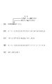
【図面の簡単な説明】
【図1】本発明を適用する画像処理装置の第1の基本構成を示す図である。
【図2】本発明を適用する画像処理装置の第2の基本構成を示す図である。
【図3】図1の構成における処理を簡略化して示したフローチャートである。
【図4】初期状態の符号化フェーズにおけるデータフローとメモリ内容を表わす図である。
【図5】符号化・再符号化フェーズにおけるデータフローとメモリ内容を表わす図である。
【図6】転送フェーズにおけるデータフローとメモリ内容を表わす図である。
【図7】転送フェーズ後の符号化フェーズにおけるデータフローとメモリ内容を表わす図である。
【図8】図1の構成における処理の詳細を示すフローチャートである。
【図9】図1の構成の変形例における符号化・再符号化フェーズにおけるデータフローとメモリ内容を表わす図である。
【図10】図9の変形例における転送フェーズにおけるデータフローとメモリ内容を表わす図である。
【図11】図9の変形例における転送フェーズ後の符号化フェーズにおけるデータフローとメモリ内容を表わす図である。
【図12】図2の構成における処理手順を示すフローチャートである。
【図13】図2の構成における、初期状態の符号化フェーズにおけるデータフローとメモリ内容を表わす図である。
【図14】図2に構成における、転送フェーズにおけるデータフローとメモリ内容を表わす図である。
【図15】図2の構成における、符号化・再符号化フェーズにおけるデータフローとメモリ内容を表わす図である。
【図16】図2の構成における、符号化・再符号化フェーズ後の符号化フェーズにおけるデータフローとメモリ内容を表わす図である。
【図17】本発明の第1の実施形態における装置のブロック構成図である。
【図18】第1の実施形態における処理手順を示すフローチャートである。
【図19】第1の実施形態における可逆符号の符号化データと再符号化後の符号化データを示す図である。
【図20】第1の実施形態における他の構成を示す図である。
【図21】第2の実施形態における可逆符号の再符号化後の符号化データと再々符号化後の符号化データを表わす図である。
【図22】第3の実施形態における装置のブロック構成図である。
【図23】第3の実施形態における処理手順を示すフローチャートである。
【図24】第3の実施形態における可逆符号の符号化データと再符号化後の符号化データを示す図である。
【図25】第3の実施形態における他の構成を示す図である。
【図26】第4の実施形態における可逆符号の再符号化後の符号化データと再々符号化後の符号化データを表わす図である。
【図27】第3の実施形態における初期状態の符号化フェーズにおけるデータフローとメモリ内容を表わす図である。
【図28】第5の実施形態における装置のブロック構成図である。
【図29】第5の実施形態における処理手順を示すフローチャートである。
【図30】第5の実施形態における可逆符号の符号化データと再符号化後の符号化データを示す図である。
【図31】第5の実施形態における他の構成を示す図である。
【図32】第6の実施形態における可逆符号の再符号化後の符号化データと再々符号化後の符号化データを表わす図である。
【図33】第5の実施形態における初期状態の符号化フェーズにおけるデータフローとメモリ内容を表わす図である。[0001]
BACKGROUND OF THE INVENTION
The present invention relates to an image processing apparatus having a function of compressing and encoding image data with image area information accompanying the image data within a predetermined code amount.
[0002]
[Prior art]
Conventionally, the JPEG method using discrete cosine transform and the method using Wavelet transform are often used as still image compression methods. Since this type of encoding method is a variable length encoding method, the amount of code changes for each image to be encoded.
[0003]
In the JPEG method, which is an international standardization method, only one set of quantization matrices can be defined for an image. Therefore, without pre-scanning, the code amount cannot be adjusted and used in a system that stores in a limited memory. There was a danger of causing memory over.
[0004]
In order to prevent this, in order to adjust the code amount by changing the compression rate and re-reading the original when the code amount exceeds the planned code amount, or by estimating the code amount by pre-scanning in advance , The method of resetting the quantization parameter was taken.
[0005]
On the other hand, the image information includes, in addition to the original image data, image area information accompanying the image data. The image area information is mainly used for color processing and tone adjustment in the image output unit in order to improve the appearance at the time of image output. For natural images that contain both chromatic and achromatic colors and black characters that are often found in the original, changing the type of ink used in the same black makes the natural image look like a natural image while outputting clear characters. I can do it.
[0006]
As described above, each pixel has 1-bit attribute flag data indicating whether it is a chromatic color or an achromatic color and whether it is a character portion, thereby improving the image quality of the output image at the time of image output, particularly at the time of printout. I can do it. The image area information includes information other than the above.
[0007]
In order to compress image information, it is necessary to compress not only the image data but also the image area information. Image area information is a collection of binary data, and in order to compress it, it is basically necessary to use a reversible encoding method. Conventionally, Packbits and JBIG encoding methods have been used for compression of image area information.
[0008]
However, only by compressing the image area information with these encoding methods, the code amount cannot be adjusted, and when used in a system that stores in a limited memory, there is a risk of causing a memory overload. It was a problem.
[0009]
[Problems to be solved by the invention]
However, conventionally, only compression of image data has been studied, and compression of image area information has been rarely studied. In addition, there is almost no possibility of keeping the code amount after compression of the image area information within a target value, and the image area information is simply encoded using a certain encoding method.
[0010]
The present invention has been made in view of the above conventional example, and provides an effective image processing apparatus for controlling the input of image area information within a code amount within a target value, a control method thereof, a computer program, and a storage medium. It is something to try.
[0011]
[Means for Solving the Problems]
In order to solve this problem, for example, the image processing of the present inventionMethodHas the following configuration. That is,
An image processing method for inputting image area information for each pixel of multi-value image data and compressing and encoding the image area information
A first encoding step for lossless encoding of the input image area information;
A second encoding step of expanding the lossless encoded data in the first encoding step and lossless encoding again;
Monitoring the amount of encoded data obtained in the first encoding step, and determining whether or not the amount of encoded data satisfies a predetermined standard,
When it is determined by the monitoring step that the encoded data amount satisfies a predetermined standard, the first encoding step converts the image area information that is subsequently input according to a predetermined condition, and then performs lossless encoding. In the second encoding step, the image area information represented by the encoded data already encoded by the first encoding means is converted according to a predetermined condition and then re-encoded.
[0012]
DETAILED DESCRIPTION OF THE INVENTION
Hereinafter, embodiments according to the present invention will be described with reference to the accompanying drawings. First, basic portions will be described.
[0013]
FIG. 1 is a functional block configuration diagram of an
[0014]
The
[0015]
The
[0016]
The first
[0017]
The
[0018]
The encoding
[0019]
The encoded data after the compression rate change is also stored in the
[0020]
Furthermore, the encoding
[0021]
The
[0022]
The encoded data output from the
[0023]
The second memory control unit detects whether or not the re-encoding process has been completed. That is, when there is no more data to be read for the re-encoding process, the encoding
[0024]
The count value obtained by the
[0025]
The
[0026]
Whether or not the count value of the
[0027]
FIG. 8 is a flowchart showing the process flow in the configuration shown in FIG. 1, but for the sake of simplicity, description will be given first according to the simplified flowchart shown in FIG.
[0028]
As described above, the
[0029]
The flowchart of FIG. 3 is roughly divided into the following three processing phases.
(1) Encoding phase
(2) Encoding / re-encoding phase
(3) Transfer phase
FIG. 4 to FIG. 7 show how the image data, encoded data, etc. flow and are processed and stored in the memory in each of the above processing phases in an easy-to-understand manner. .
[0030]
FIG. 4 shows an initial state of the encoding phase corresponding to steps S303 and S305 in the flowchart of FIG. 5 shows the processing state of the encoding / recoding phase corresponding to steps S307 to S315, FIG. 6 shows the processing state of the transfer phase corresponding to step S317, and FIG. 7 shows the encoding phase after the transfer phase. Indicates processing status. Hereinafter, each phase will be described.
[0031]
<< Encoding Phase >>
Encoding processing of image data for one page starts from initial setting of encoding parameters (step S301). Here, the upper limit value of the encoded data amount uniquely determined from the image size to be encoded (paper size read from the
[0032]
In step S303, the
[0033]
Next, in step S305, it is detected whether the count value of the data amount has exceeded the upper limit value. If not, the JPEG encoding process in step S303 is continued. This is the initial encoding phase.
[0034]
The encoded data output from the
[0035]
<< Encoding / Recoding Phase >>
When the encoding process of the
[0036]
That the count value of the data amount of the encoded data exceeds the set upper limit value means that the data amount after compression does not fall within the target value. Therefore, since it is meaningless to continue the encoding process using the same quantization step, it is changed to the quantization step Q2 having a larger quantization step width than Q1 so that the data amount is smaller than before. is there.
[0037]
After changing the quantization step, in step S311, the encoding process of the
[0038]
Specifically, in this re-encoding process, these values are set to 2 for each quantized value after the encoded data is once Huffman-decoded.nThis is realized by performing a Huffman coding again after performing a bit shift process that produces a result similar to that obtained by dividing by. This method enables high-speed re-encoding processing in that the quantization step is changed only by bit shift and that inverse orthogonal transformation or re-orthogonal transformation processing is not performed. In
[0039]
Since the amount of data after re-encoding is smaller than the amount of encoded data before re-encoding, as shown in FIG. 5, after re-encoding in the memory area where the code before re-encoding was stored Can be stored so as to be overwritten. When the re-encoding process is completed, the data amount of the encoded data of the vertical stripes (1) decreases to the data amount of the encoded data of the diagonal stripes (1) shown in FIG.
[0040]
Steps S307 to 315 described above are processes performed in the encoding / recoding phase.
[0041]
<< Transfer Phase >>
When the re-encoding process is completed, a transfer process is performed in step S317. In the transfer process, as shown in FIG. 6, encoded data of diagonal stripes (2) stored only in the
[0042]
When the transfer phase ends, the process returns to the encoding phase of steps S303 and S305, and the code of the diagonal stripe (4) is output from the
[0043]
Therefore, by repeating the encoding phase, the encoding / re-encoding phase, and the transfer phase, the code that finally compresses the image data of one page below the data amount setting value is stored in the first memory. I can do it. In addition, the
[0044]
The flowchart shown in FIG. 3 describes only the processing corresponding to each phase shown in FIGS. 4, 5, and 6 so that the explanation can be easily understood. In practice, however, the input of image data for one page ends in some phase. Therefore, the correspondence after that is slightly different depending on which phase it is completed. FIG. 8 is a flowchart showing the flow considering this. The flowchart in FIG. 8 considers the relationship between the completion of input of image data for one page and the various processes described with reference to FIG. 3. Here, steps S801, S803, S805, and S807 are added to the flowchart in FIG. It has been added.
[0045]
Steps S801, S803, and S805 detect that the input of image data for one page from the
[0046]
If it is detected that the input of image data for one page has been completed in the encoding phase and the transfer phase (steps S801 and S805), the process proceeds to step S807, where the compression encoding process for the page is ended, and the next process is performed. If there is more than one page of image data, the compression encoding process of the next one page of image data is started, and if there is no image data, a stop state is entered.
[0047]
On the other hand, when the end of input of image data for one page is detected in the encoding / re-encoding phase (step S803), the
[0048]
The above is the operation, and is also the operation description of FIG.
[0049]
<Modification of memory storage method>
9 and 10 are diagrams showing modifications of the memory storing method shown in the conceptual diagrams of FIGS.
[0050]
In the conceptual diagram of FIG. 5, in the encoding / re-encoding phase, the encoded data output from the
[0051]
When viewed from the
[0052]
Therefore, in the case of this modification, the encoded data is divided into certain units and managed as a file or a packet in order to cope with this. Specifically, a file management table or a packet management table is created and managed separately.
[0053]
As one method, when data from the
[0054]
The
[0055]
The encoding phase after the transfer phase in the conceptual diagram of FIG. 10 is almost the same as the two encoding phases described above (FIGS. 4 and 7), and the code storage state in the first memory is shown in FIG. It is only slightly different as shown in. Therefore, the above description and this modification are the same in that the three phases are repeated.
[0056]
Next, a second basic configuration example (the configuration described so far is referred to as a first example) for performing a characteristic encoding process in the present invention will be described with reference to FIG.
[0057]
FIG. 2 is a block diagram of the
[0058]
A significant difference from the
[0059]
In this example, a case where the compression rate applied by the
[0060]
The encoded data output from the
[0061]
On the other hand, the encoded data encoded by the
[0062]
When the
[0063]
Then, the encoding
[0064]
In short, since the count value of the
[0065]
Furthermore, the
[0066]
For example, the quantization step S in the
[0067]
Here, although the magnification ratio of the quantization step is set to double, it is not limited to this, and needless to say, it can be arbitrarily set. The encoded data output from the switched encoding
[0068]
Then, the
[0069]
The
[0070]
The
[0071]
Regardless of whether the re-encoding process is completed or not, if the image data from the
[0072]
FIG. 12 is a flowchart showing the process flow in the configuration of FIG.
[0073]
As described with reference to FIG. 2, when there are two encoding units, image data for one page is encoded based on the flowchart shown in FIG. Note that the description of FIG. 12 is mostly similar to FIG. 8, which is a flowchart in the case of one encoding unit, and those skilled in the art will fully understand the features of the second example from the above description. Since it will be possible, the process will be described in three phases as in the case of one encoding unit, and the differences from FIG. 8 will be mainly described.
[0074]
The biggest difference between the flow of FIG. 8 described above and the flow of this example is that the transfer processing in step S317 is moved between step S307 and step S309. In short, it can be regarded that the encoding / re-encoding phase and the transfer phase are switched (the exception is the discarded processing of the encoded data in step S307).
[0075]
In the initial setting of the encoding parameter in step S301, the quantization step Q1 is set in the
[0076]
In the encoding phase, steps S801, S303, and S305 are repeatedly executed. Steps S801 and S305 are the same processing as in the case of one encoding unit, but only the encoding processing in step S303 is different as shown in FIG.
[0077]
In order to increase the compression rate of the encoded data stored in the
[0078]
When the amount of data stored in the
[0079]
In this second example, since it is a wasteful idea to have encoded data having the same compression rate in the two
[0080]
Specifically, first, as shown in FIG. 15, in the encoding / re-encoding phase subsequent to the transfer phase, each quantization applied to the two encoding
[0081]
In the second example, as in the first example, in the re-encoding process, these values are set to 2 for each quantized value after the encoded data is once Huffman-decoded.nThis is realized by performing a Huffman coding again after performing a bit shift process that produces a result similar to that obtained by dividing by. This method is capable of high-speed re-encoding processing in that the quantization step is changed only by bit shift and the inverse orthogonal transformation or re-orthogonal transformation processing is not performed.
[0082]
In the case where there are two encoding units as in the second example, as shown in FIG. 15, the encoded data and re-encoded data are mixedly stored in the
[0083]
In FIG. 12, when the end of the re-encoding process is detected in step S315, the process proceeds to the encoding phase (steps S801 and S303) again. In the encoding phase after the encoding / re-encoding phase, as shown in FIG. 16, the encoded data held in the two
[0084]
The state of the encoding phase shown in FIG. 16 is the initial state of the encoding phase (FIG. 13) except that the method of mixing the quantization step and the encoded data is different before and after the re-encoding process. Is the same. Therefore, by repeating the encoding phase, the transfer phase, and the encoding / re-encoding phase, the encoded data that is finally compressed to be equal to or less than the set upper limit value of the image data for one page is surely stored in the first memory. 204 can be stored.
[0085]
Note that since the arrangement order of the transfer phase and the encoding / re-encoding phase is reversed from the description of the first example, the input end detection of image data for one page, which has been performed after the transfer processing in FIG. (Step S805) has almost the same timing as the input end detection of image data for one page (step S803) performed in the encoding / recoding phase. The two detection processes are functionally the same as step S805 and the timing is the same as step S803. Therefore, these two steps detect the end of input of image data for a new page. Are integrated as a step to be performed and described as step S1201.
[0086]
In the first and second examples described above, the first memory and the second memory have been described as physically separate memories. This is advantageous because access to the two memories can be independent, which is a feature of the present invention. However, the case where the first memory and the second memory are not physically separate memories is also included in the scope of the present invention. Two areas corresponding to the first memory and the second memory are secured on one physical memory, the first memory is the first memory area, and the second memory is the second memory. It can be understood that the present invention can be realized with a single memory by re-reading the above description by rephrasing the area.
[0087]
Further, when each of the above examples is realized with one memory, some of the data transfer processes described in the transfer phase are unnecessary. The details can be easily imagined each time, so the explanation will be omitted. However, when the two areas are used strictly separated, data transfer processing is necessary as in the case of physically having two memories. If the same data is shared between the two areas, not only the data transfer process becomes unnecessary, but also the storage capacity can be reduced.
[0088]
For example, when the encoded data held in the second memory area is transferred to the first memory area, two pieces of information of the head address and the data size in which the encoded data is stored are stored in the second memory. The same effect as that obtained by transferring the encoded data can be obtained only by transferring the data from the control unit to the first memory control unit.
[0089]
When the encoded data is stored in a file format or a packet format, the information transferred between the memory control units is slightly increased, and it is necessary to transfer management table information related to the encoded data. Nevertheless, it is more efficient than transferring encoded data.
[0090]
Now, according to the above-described image processing apparatus, even when the input image data is encoded, even if it exceeds the target size, processing is performed so that the input is continued and the target size is maintained. In the present invention, in addition to controlling the code amount of the compressed data of the image data, the code amount of the data obtained by encoding the image area information attached to the image data is also controlled in the present invention. Is.
[0091]
In the embodiment described below, it will be described how image area information is encoded and the amount of encoded data is controlled.
[0092]
<First Embodiment>
FIG. 17 shows a first embodiment in which the present invention is applied to the above-described image processing apparatus. In this figure, the present invention is applied to the basic configuration shown in FIG. 1, and the same functional blocks as those in the configuration of FIG.
[0093]
Image data input through the
[0094]
On the other hand, the image data is supplied to an image area
[0095]
The image area information generated by the image area
[0096]
The operation of the image area
[0097]
First, it is determined whether the area is a character / line drawing area or a halftone area. In the case of a character / line drawing area, the brightness (or density) of the background changes sharply with respect to the background. On the other hand, when the pixel is in the halftone area, the luminance (or density) of the target pixel has a small change with respect to the adjacent pixel. Therefore, the luminance of the target pixel is set to Li, L and Li-1, Li + 1When defined as
| Li-Li-1| > T
Or
| Li-Li + 1| > T
If it is, it can be determined that the pixel of interest is at the edge of the character line image. Here, | x | indicates the absolute value of x.
[0098]
Note that the formula for determining whether or not the density changes sharply is not limited to the above. For example,
| 2Li-Li-1-Li + 1| > T
Or may be determined not only in the one-dimensional direction but also in the two-dimensional direction (however, in the case of determining in two dimensions, the image area
[0099]
On the other hand, the determination of chromatic / achromatic color is made. Since the input image data is read by the scanner, the data format is R, G, B.
[0100]
An achromatic color means that each color component of RGB has the same luminance,
R = G = B
Is determined as an achromatic color, and if not satisfied, it is determined as a chromatic color. However, since it is necessary to consider the accuracy of the CCD that the scanner device has,
B−Δ <R <B + Δ
R−Δ <G <R + Δ
G-Δ <B <G + Δ
If all of the above are satisfied, it may be determined as an achromatic color (Δ is an appropriate small numerical value), and the others may be determined as chromatic colors.
[0101]
In some cases, the RGB color space is converted into, for example, luminance, hue, and saturation (for example, Lab color space), and when the saturation is below a predetermined value, it is determined to be an achromatic color, and when it exceeds a predetermined value, it is determined as a chromatic color. It would be fine.
[0102]
As described above, the image area
[0103]
Returning to the description of FIG. As described above, the generated image area information is blocked by the
[0104]
By the way, when encoding image area information, multi-value irreversible compression such as JPEG used for compression of normal image data is not suitable. Therefore, we decided to use run-length encoding such as JBIG or PackBits which is lossless compression. The
[0105]
The encoded image area information is stored in the
[0106]
The
[0107]
First, the lossless
[0108]
The following two methods were prepared for increasing the run length.
Process P1: All the chromatic / achromatic identification information at the pixel position where the character / line drawing / halftone pixel identification bit indicates a halftone pixel is changed to a chromatic color.
Process P2: The character / line drawing / halftone pixel identification bit is changed to indicate the halftone pixel.
[0109]
If the
[0110]
The reason why the chromatic / achromatic color identification information is chromatic is that the chromatic color space includes an achromatic color in the color space, and thus does not pose a major problem. Also, the character / line drawing / halftone identification information is changed to halftone for the same reason.
[0111]
In any case, by changing the image area information, the entropy is reduced, so the data amount after run-length encoding is reduced. The attribute data after re-encoding is stored again in the
[0112]
On the other hand, the
[0113]
In this way, when it is determined that the target value will be exceeded again while the processing is switched to the process P1 and the image area information is being encoded, the
[0114]
The above is summarized as follows.
[0115]
The
[0116]
If it is determined that the target value is exceeded again during the processing by the processing P1, this time, the
[0117]
As a result, the image area information can be losslessly encoded within the target value (target size) while continuing to input the image data from the
[0118]
Next, a flowchart showing the processing contents of the first embodiment is shown in FIG. 18, and the description will be given using this flowchart. As described above, the process according to the present embodiment is roughly divided into two processes. One is a lossless encoding process and the other is a re-encoding process.
[0119]
The encoding process includes an image area information conversion process in step S1805 and a lossless encoding process in step S1807. The re-encoding process includes a decoding process in step S1815, an image area information conversion process in step S1817, and a step. And the re-encoding process of S1819.
[0120]
The other steps are conditional branching and start and end steps, except for the change in the image area information changing process of S1813.
[0121]
First, encoding processing of image area information is started from step S1801. In the next step S1803, it is detected whether or not the input of image area information for one page of the image has been completed. If it has been completed, the process proceeds to step S1821, and if it has not been completed, that is, the input of image area information has been completed. If there is, the image area information conversion process in step S1805 is performed.
[0122]
In the initial state where the re-encoding process has not been started yet, nothing is performed in the image area conversion process, and the input image area information is directly encoded by the lossless encoding process in the next step S1807.
[0123]
In the next step S1809, it is determined whether or not the re-encoding process is being performed. If the re-encoding process is being performed, the re-encoding process including steps S1815 to S1819 is performed. For example, the process goes to step S1811 to determine whether or not the encoded data (code amount) exceeds the set value.
[0124]
If not, the process returns to step S1803, and the encoding process is repeated. If it is over, the processing content in the image area information conversion process is changed. With this change, the contents of the image area conversion processing in steps S1805 and S1817 change. Specifically, in the initial state, processing P1, that is, the chromatic / achromatic color at the pixel position in which the character / line drawing / halftone identification information is determined to be halftone in the input image area information. All of the identification information is chromatic.
[0125]
After changing the image area information conversion processing content, re-encoding processing is performed. In the re-encoding process, in step S1815, the encoded image area information is decoded and returned to the data before encoding. In the next step S1817, the image area information conversion process is performed, and the image area information change process is performed. In the next step S1819, the converted image area information is losslessly encoded again.
[0126]
When the re-encoding process is completed, the process returns to step S1803, and if there is input of image area information, it is encoded. If the code amount exceeds the set value even once, the image area information conversion process content is changed, and after the image area information conversion process in step S1805 is replaced with the process P1, the lossless encoding is performed in step S1807. .
[0127]
Thus, after replacing the process P1, if it is determined again in step S1811 that the code amount has exceeded the target value, in step S1813, the image area change in steps S1805 and S1817 is changed to the process P2. To do.
[0128]
In any case, if all the input of the image area information is completed and the re-encoding process is not performed, the process proceeds to step S1823, and the image area information encoding process is ended.
[0129]
As described above, according to the first embodiment, image data is encoded within a target size without interrupting or re-inputting one or one page of image data, The image area information of the image can be losslessly encoded within the target size.
[0130]
An example in which the lossless encoding unit and the lossless code re-encoding unit in the embodiment employ packbits encoding will be described below.
[0131]
Here, specific processing in this embodiment when 6 bits data “000000” is added to 2 bits image area information per pixel to 8 bits and then Packbits encoding is performed as a lossless code. The contents will be described with reference to FIG.
[0132]
In the 8-bit data before Packbits encoding, as shown in FIG. 19A, the upper 6 bits are all 0, and the corresponding pixel data identifies the character / line drawing / halftone on the upper side of the lower 2 bits. It is assumed that a flag indicating chromatic / achromatic color is stored in the lower side. Therefore, the values that the 8-bit data can take are values of 0 or more and 3 or less. In order to simplify the description, it is assumed that one-dimensional image area information is output from the image area
[0133]
The 8-bit data is output from the image area
[0134]
When this is encoded by Packbits, it is compressed into data shown in FIG. In the compressed data, a negative value represents the number of continuous data, and a non-continuous data number represents a positive value. These are length information, and it is possible to determine whether continuous data continues or non-continuous data continues from the sign bit of the length information. Each data after compression is 8 bits (1 byte) as in (b). The maximum value that can be represented with 1-byte length information is about 128, which is half of 255. If the length information is less than that, it is encoded with a set of length information and the image area flag data group that follows. If it exceeds that, it is divided into a plurality of sets of length information + image area flag data group and encoded.
[0135]
Let us take a closer look at the compressed data in FIG. Since the first length information “−4” is a negative value, it represents the number of continuous data as described above, and represents that four image area flag data “1” immediately after the length information follow.
[0136]
The next data “4” is also length information, but this time is a positive value, which indicates that four non-continuous data continues. Therefore, the four data “2, 3, 2, 3” following “4” represent discontinuous data. In FIG. 19C, only the positive length information is underlined so that the length information and the image area flag data can be easily distinguished.
[0137]
“−5” next to the non-continuous data is also length information of the continuous data, and represents that five image area flag data “2” immediately after the length information follow. The next underlined data “3” is length information of non-continuous data, the following three data “1, 0, 1” are image area flag data, and the next “−6, 0” It shows that 6 pieces of data “0” continue.
[0138]
What happens when the reversible
[0139]
The encoded image area data is once decoded and returned to the data of FIG. 19B, and then converted to the data of FIG. 19D by replacing the flag data. If this is encoded again with Packbits, the encoded data shown in FIG. It can be seen that the encoded data of 15 bytes before re-encoding is reduced to 6 bytes after re-encoding.
[0140]
In spite of performing the above re-encoding process, when the count value of the total code amount again exceeds the target value set in the register in the
[0141]
In the new re-encoding process, the remaining 1-bit image area flag is also replaced with “1”. As a result, the value of all image area flag data (8 bits) is “3”, and when the number of data bytes is N, the amount of data after encoding is approximately (2N / 128) +2 bytes.
[0142]
This is because every time the number of continuous data exceeds 128, a new set of encoded data (length information and continuous data) of 2 bytes increases.
[0143]
Since the Packbits encoding circuit, decoding circuit, and data conversion circuit are well-known techniques, descriptions of individual circuit configurations are omitted.
[0144]
In the above embodiment, for the sake of simplification, the image area flag of each pixel has been described as 2 bits. However, as described above, other information may be added as the image area flag.
[0145]
Theoretically, the process for converting the image area information is 2 if the type of the image area is N bits.NThere will be. However, the compression ratio needs to be high every time conversion is performed. In any case, the larger the number of bits of the image area information, the more the number of re-encoding processes can be increased, and the code amount can be controlled in multiple stages.
[0146]
As described above, the lossless encoding process of the image area information data is controlled independently of the compression encoding process of the image data, and each is stored in data within the target code amount.
[0147]
The encoded two types of data are multiplexed when output to a network device, an image output device, a mass storage device, or the like connected to the outside. In consideration of the multiplexing, the units for encoding the two types of data are matched to the same size, and the encoded data generated by encoding one unit is managed and stored as one packet or file. . When multiplexing, two types of packet data having the same image position are connected in the order of, for example, image data and image area data to form one packet and output to the outside.
[0148]
Since the two encoding processes are controlled independently, the image data compression encoding processing unit may have another configuration. Therefore, even if
[0149]
<Modification of First Embodiment>
In the above-described embodiment, two bits of the image area component information are a character / line drawing / halftone identification bit, the other is a chromatic / achromatic bit, and has a value of 0 to 3 as one value. Treated as a thing. However, the character / line drawing / halftone identification information and the chromatic / achromatic identification information are originally independent information. Therefore, a block composed of character / line drawing / halftone identification bits and a block composed of chromatic / achromatic identification bits may be made independent and encoded independently. . As a result, each bit in each block is composed of only the same type of bits, so that compression efficiency can be increased in the first stage, and as a result, some bits of image area information are fixed. By reducing the probability of conversion to a value, it is possible to increase the probability of compression encoding with the original image area information.
[0150]
<Second Embodiment>
In the second embodiment, a description will be given of a processing method capable of finely controlling the amount of code by increasing the number of re-encoding processes even when the number of bits of image area information is the same as that in the first embodiment. The configuration of this embodiment is the same as that of the first embodiment, and the difference is the image area flag data compression method in the
[0151]
In the first embodiment, the image area flag data is replaced with a fixed value bit by bit, but in the second embodiment, the number of states is degenerated. For example, in a 2-bit image area flag, four states can be represented, but this is reduced to 3 states by the first re-encoding process and reduced to 2 states by the second re-encoding process. The information entropy before encoding is reduced, and the data amount (encoding amount) after encoding is reduced finely.
[0152]
When the first embodiment is expressed using the term number of states, it can be said that the number of states is reduced to half each time image area information is re-encoded.
[0153]
In the first embodiment, the number of states is substantially halved in one re-encoding process, whereas in the present embodiment, the number of states is reduced by one, so that the code amount can be reduced finely. Naturally.
[0154]
The processing result of the second embodiment will be described with reference to FIGS.
[0155]
FIG. 19A shows the same data as the image area flag data shown in FIG. 19B, in which all of the two 2-bit states exist. The definition of the four states is as follows.
(1) Chromatic character line drawing (corresponding to data “3”)
(2) Achromatic line drawing (corresponding to data “2”)
(3) Chromatic halftone (corresponds to data “1”, also called chromatic image part)
(4) Achromatic halftone (corresponds to data “0”, also called achromatic image part)
In the second embodiment, in the first re-encoding process, two states of (3) chromatic halftone and (4) achromatic halftone are combined into one of the above four states. State (3 ′) is degenerated to a halftone. As a result, the following three states are obtained. This corresponds to the process P1.
(1) Chromatic character part
(2) Achromatic character part,
(3 ') Halftone
Specifically, the above state is degenerated by replacing data “0” with “1”. The data after the state degeneration is changed to the data shown in FIG. If this is Packbits encoded, the encoded data shown in FIG. It can be seen that the code amount is somewhat smaller than that of the encoded data before re-encoding in FIG.
[0156]
In the second re-encoding process, the two states of (1) a chromatic color character portion and (2) an achromatic color character portion are merged and degenerated into one state (1 ′) character portion. As a result, the following two states are obtained.
(1 ') Character part
(3 ') Non-character part
This time, the data “2” is replaced with “3” to reduce the state. The data after the state degeneration is changed to the data shown in FIG. This data is the same as the data in FIG. Encoded data obtained by Packbits encoding FIG. 21 (e) is naturally the same encoded data as FIG. 19 (e).
[0157]
In the first embodiment, the 15-byte data before re-encoding is reduced to 6 bytes by one re-encoding, but in this embodiment, it is reduced to 11 bytes by the first re-encoding, and 2 It is finally reduced to 6 bytes by the second re-encoding. Eventually, in the second embodiment, it is possible to obtain a code amount that varies finely and decreases that cannot be obtained in the first embodiment. Therefore, compressed image area flag data close to the target code amount can be obtained.
[0158]
<Application example>
In the first embodiment and its modifications, and in the second embodiment, an apparatus for reading an image from an image scanner is taken as an example, and the functional operation of the apparatus has been described. Most of the functions (including the encoding process) can be realized by the computer program as described above.
[0159]
Therefore, the present invention may be applied to an application program that operates on a general-purpose information processing apparatus such as a personal computer. In the case of application to an application program, a GUI may be provided such as allowing the user to specify an image file to be compressed and allowing the user to select a target size. The target value at this time can be set arbitrarily by the user, but setting with numerical values is difficult to understand, so it should be selected from an intuitive menu that takes into account the document size and image quality (high, medium, low, etc.). It would be good to make a decision.
[0160]
Further, although the quantization step has been described as an example of the encoding parameter of the encoding unit, when data having different compression ratios are mixed, as long as the image quality between them does not cause a sense of incongruity, other The parameters may be used. However, for example, in the configuration of FIG. 1, in order to make the re-encoded data from the
[0161]
Further, as described above, the present invention can be realized by an application program that runs on a general-purpose device, and therefore the present invention includes a computer program. In addition, since the computer program is usually performed by setting or copying or installing a storage medium such as a floppy disk or CDROM in the apparatus, such a storage medium is naturally included in the scope of the present invention.
[0162]
In the embodiment, the image data is input from the scanner. However, the present invention may be applied to a printer driver that operates on a host computer. In the case of application to a printer driver, when data to be printed is received from a higher-level process (such as an application), it is of course possible to determine whether the data is a halftone image or a character / line image. The configuration related to the area information generation processing can be omitted or simplified.
[0163]
The present invention can also be applied to a combination of a computer program and appropriate hardware (such as an encoding circuit).
[0164]
As described above, according to the first and second embodiments, the decoding means for decoding losslessly encoded image area information and the image area information so that the information entropy of the image area information is reduced. Image area information converting means for rewriting or deleting a part of the image area information, and re-encoding for reversibly encoding the image area information obtained by converting the image area information decoded by the decoding means by the image area information converting means. Encoding means, lossless encoding means including the information conversion means, and storage means capable of storing data obtained by encoding image area information associated with image data for at least one page,
By controlling both the image area information converting means provided in the lossless converting means and the image area information converting means in the preceding stage of the re-encoding means according to the amount of the encoded data, an image for one page is obtained. The area information can be contained in a desired encoded data amount.
[0165]
<Third Embodiment>
The third embodiment will be described. The third embodiment performs substantially the same operation as the first embodiment described above, but the structure is different. FIG. 22 is a block configuration diagram thereof. The constituent elements having the same reference numerals as those in FIG. 1 have the same operation (encoding process of image data), and therefore the description thereof will be omitted. Hereinafter, the encoding part of the image area information in the third embodiment will be described. explain.
[0166]
Image data (multi-valued color image data) input via the
[0167]
The image area
[0168]
The generated image area information is blocked by a
[0169]
Multi-value irreversible compression such as JPEG used for compressing image data is inconvenient for use in compressing image area information that is a collection of binary data. Therefore, a run such as JBIG or PackBits that is reversible compression is used. The
[0170]
The reversibly encoded image area information is stored in the
[0171]
FIG. 27 shows the state of the memory in the initial state of encoding. 4 is different from FIG. 4 in that a storage area for image area information is provided as shown. The encoded image area information is sequentially stored in this storage area via the
[0172]
As described above, the coding
[0173]
In the third embodiment, at the same time, the encoding
[0174]
The
[0175]
When the lossless
[0176]
On the other hand, the
[0177]
The process is continued until the image area flag data to be re-encoded disappears and the re-encoding process is completed.
[0178]
The encoding
[0179]
Next, the processing content (encoding process of image area information) of the third embodiment will be described with reference to the flowchart of FIG. The process of the third embodiment is roughly divided into two processes as described above. One is a lossless encoding process and the other is a re-encoding process.
[0180]
The encoding process is realized by the image area information conversion process in step S2305 and the lossless encoding process in step S2307. The re-encoding process is realized by the decoding process in step S2315, the image area information conversion process in step S2317, and the re-encoding process in step S2319.
[0181]
The other steps are conditional branch and start and end steps, except for the change in the image area information change processing in S2313.
[0182]
First, from step S2301, encoding processing of image area information is started. In the next step S2303, it is detected whether or not the input of the image area information for one page of the image has been completed. If it has been completed, the process goes to step S2321, and if it has not been completed, that is, the input of the image area information has been completed. If there is, the image area information conversion process in step S2305 is performed.
[0183]
In the initial state where the re-encoding process has not been started yet, nothing is performed in the image area conversion process, and the input image area information is directly encoded in the lossless encoding process of the next step S2307.
[0184]
In the next step S2309, it is determined whether or not the re-encoding process is being performed. If the re-encoding process is being performed, the re-encoding process including steps S2315 to S2319 is performed. In step S2311, it is determined whether re-encoding of the image data is performed.
[0185]
If the control signal that the encoded data has exceeded the predetermined target value has not been received from the encoding
[0186]
After changing the image area information conversion processing content, re-encoding processing is performed. In the re-encoding process, in step S2315, the encoded image area information is decoded and returned to the data before encoding. In the next step S2317, the image area information conversion process is performed, and a part of the image area information is discarded or replaced with a fixed value. In the next step S2319, the converted image area information is losslessly encoded again.
[0187]
When the re-encoding process is completed, the process returns to step S2303, and if image area information is input, it is encoded. When the code amount of the image data exceeds the set value even once and re-encoding is started, the image area information conversion processing content is changed in conjunction with it, and part of the image area information conversion processing in step S2305 After the image area flag data is discarded or replaced with a fixed value, lossless encoding is performed in step S2307.
[0188]
If the re-encoding process continues even after all the image area information has been input, the process proceeds from step S2303 to step S2321, where it is determined that the re-encoding process is in progress, and the steps S2315˜ The re-encoding process consisting of S2319 is performed.
[0189]
If all the input of the image area information is completed and the re-encoding process is not performed, the process proceeds to step S2323, and the image area information encoding process is ended.
[0190]
Further, when the code amount of the image data once exceeds the set value even once, all the bits indicating the chromatic color / achromatic color in the image area information are changed to chromatic colors.
[0191]
Next, the third embodiment in the case where Pac kbit s encoding is performed as a lossless code after 6-bit data “000000” is added to 2-bit image area information per pixel to form 8 bits. The specific processing contents in will be described in more detail with reference to FIG.
[0192]
As shown in FIG. 24A, the upper 6 bits are all 0, and the corresponding pixel data is the character line drawing area on the upper side of the lower 2 bits. , Halftone or flag bits, and flag bits representing chromatic or achromatic colors are assigned to the lower side. Therefore, the values that the 8-bit data can take are values of 0 or more and 3 or less.
[0193]
It is assumed that the 8-bit data is output from the image area
[0194]
When this is packed bits encoded, it is compressed into the data shown in FIG. In the compressed data, a negative value represents the number of continuous data, and a non-continuous data number represents a positive value. These are length information, and it is possible to determine whether continuous data continues or non-continuous data continues from the sign bit of the length information. Each data after compression is 8 bits (1 byte) as in FIG. The maximum value that can be represented with 1-byte length information is about 128, which is half of 255. If the length information is less than that, it is encoded with a set of length information and the image area flag data group that follows. If it exceeds that, it is divided into a plurality of sets of length information + image area flag data group and encoded.
[0195]
Let us take a closer look at the compressed data in FIG. Since the first length information “−4” is a negative value, it represents the number of continuous data as described above, and represents that four image area flag data “1” immediately after the length information follow.
[0196]
The next data “4” is also length information, but this time is a positive value, indicating that four non-consecutive data continue. Therefore, the four data “2, 3, 2, 3” following the “4” represent discontinuous data. In FIG. 9C, only the positive length information is underlined so that the length information and the image area flag data can be easily distinguished.
[0197]
“−5” next to the non-continuous data is also length information of the continuous data, and represents that five image area flag data “2” immediately after the length information follow. The next underlined data “3” is the length information of the non-continuous data, the following three data “1, 0, 1” are the image area flag data, and the next “−6, 0” is It shows that 6 pieces of data “0” continue.
[0198]
What happens when the above-described compressed data is re-encoded by the lossless
[0199]
The encoded image area data is once decoded and returned to the data shown in FIG. 5B, then the flag data is replaced and converted into the data shown in FIG. Then, the encoded data shown in FIG. 5E is obtained by performing Packbits encoding on the converted data again. It can be seen that the encoded data of 15 bytes before re-encoding is reduced to 6 bytes after re-encoding.
[0200]
Even after performing the above-described re-encoding process, in the case of encoding image data, if the count value of the total code amount again exceeds the set target value and the image data is re-encoded, the encoding is performed. When a control signal indicating that the image area data is also re-encoded is received from the
[0201]
In the new re-encoding process, the remaining 1-bit image area flag is also replaced with “1”. As a result, the value of all image area flag data (8 bits) is “3”, and when the number of data bytes is N, the amount of data after encoding is approximately (2N / 128) +2 bytes.
[0202]
This is because every time the number of continuous data exceeds 128, a new set of encoded data (length information and continuous data) of 2 bytes increases.
[0203]
Since the Packbits encoding circuit, decoding circuit, and data conversion circuit are well-known techniques, explanations of the specific arrangements are omitted.
[0204]
In the above description, the image area flag of each pixel has been described as 2 bits for simplification. However, as described above, there are some other information as the image area flag. In the re-encoding process, 2-bit image area flag data can be re-encoded up to 2 times, and 4-bit image area flag data can be re-encoded up to 4 times. As the number increases, the number of re-encoding processes can be increased, and the amount of codes can be controlled in multiple stages.
[0205]
As described above, the lossless encoding process of the image area flag data is controlled independently of the compression encoding process of the image data, and each is stored in data within the target code amount.
[0206]
The encoded two types of data are multiplexed when output to a network device, an image output device, a mass storage device, or the like connected to the outside. In consideration of the multiplexing, the units for encoding the two types of data are matched to the same size, and the encoded data generated by encoding one unit is managed and stored as one packet or file. . When multiplexing, two types of packet data having the same image position are connected in the order of, for example, image data and image area data to form one packet and output to the outside.
[0207]
Since the two encoding processes are controlled independently, the image data compression encoding processing unit may have another configuration. Therefore, even if
[0208]
<Fourth Embodiment>
In the fourth embodiment, a description will be given of a processing method capable of finely controlling the code amount by increasing the number of re-encoding processes even if the number of bits of image area information is the same as that of the third embodiment. The configuration of this embodiment is also the same as that of the first embodiment, and the difference is the image area flag data degeneration method in the
[0209]
In the first embodiment, the image area flag data is replaced with a fixed value bit by bit, that is, the data is degenerated bit by bit. In the present embodiment, the number of states is degenerated. For example, in a 2-bit image area flag, four states can be represented, but this is reduced to 3 states by the first re-encoding process and reduced to 2 states by the second re-encoding process. The information entropy before encoding is reduced, and the data amount (code amount) after encoding is reduced finely.
[0210]
When the third embodiment is expressed using the term number of states, it can be said that the number of states is reduced to half each time image area flag data is re-encoded.
[0211]
While the third embodiment reduces the number of states by half in one re-encoding process, the present embodiment reduces the number of states one by one, so it is natural that the code amount can be reduced finely. It is.
[0212]
The processing results of this embodiment are shown in FIGS. 26B, 26C, 26D, and 26E, and will be described.
[0213]
FIG. 26A shows the same data as the image area flag data shown in FIG. The four states are listed again as follows.
[0214]
(1) Chromatic character part (corresponding to data “3”)
(2) Achromatic character part (corresponding to data “2”)
(3) Chromatic non-character part (corresponds to data “1”, also called chromatic image part)
(4) Achromatic non-character part (corresponding to data “0”, also called achromatic image part)
In the present embodiment, in the first re-encoding process, two states of (3) a chromatic non-character portion and (4) an achromatic non-character portion are combined into one state among the four states. (3 ′) Reduce to a non-character part.
As a result, the following three states are obtained.
[0215]
(1) Chromatic character part
(2) Achromatic character part,
(3 ') Non-character part
Specifically, the above state is degenerated by replacing data “0” with “1”. The data after the state degradation is changed to the data shown in FIG. When this is packedbits encoded, the encoded data shown in FIG. It can be seen that the code amount is somewhat smaller than that of the encoded data before re-encoding shown in FIG.
[0216]
In the second re-encoding process, the two states of (1) the chromatic color character portion and (2) the achromatic color character portion are merged to be reduced to one state (1 ′) character portion. As a result, the following two states are obtained.
[0217]
(1 ') Character part
(3 ') Non-character part
This time, the data “2” is replaced with “3” to degenerate the above state. The data after the state degeneration is changed to the data shown in FIG. This data is the same as the data in FIG. The encoded data obtained by encoding this by Pac kbit s FIG. 26 (e) is naturally the same encoded data as FIG. 24 (e).
[0218]
In the third embodiment, 15-byte data before re-encoding is reduced to 6 bytes by one re-encoding, but in the fourth embodiment, it is reduced to 11 bytes by the first re-encoding. In the second re-encoding, it is finally reduced to 6 bytes. Eventually, in the fourth embodiment, it is possible to obtain a code amount that changes finely and decreases that cannot be obtained in the third embodiment, and therefore it is possible to obtain compressed data of an image area flag close to the target code amount.
[0219]
As described above, according to the third and fourth embodiments, similarly to the first and second embodiments described above, the image area information for one page can be contained in a desired encoded data amount. it can.
[0220]
<Fifth Embodiment>
The fifth embodiment will be described. The fifth embodiment performs substantially the same operation as the first embodiment described above, but the structure is different. FIG. 28 is a block configuration diagram thereof. Since the operations (image data encoding process) are the same as those of the constituent elements having the same reference numerals as those in FIG. explain.
[0221]
Image data (multi-valued color image data) input via the
[0222]
The image area
[0223]
The generated image area information is blocked by a
[0224]
Multi-level lossy compression such as JPEG used for compressing image data is inconvenient to use for compressing image data, which is a collection of binary data. The image area information is losslessly encoded by the
[0225]
The encoded image area information is stored in the
[0226]
FIG. 33 shows the state of the memory in the initial state of encoding. The difference from FIG. 4 is that an image area information storage area is provided. Basically, the encoded image area information is sequentially held in this storage area, but the encoded image data can also be stored in this storage area, as will be described later. Further, even if the encoded image area data does not fit in this storage area, if there is a surplus in the image data storage area, it is of course possible to hold it in the surplus storage area. is there.
[0227]
The
[0228]
The sixth counter adds up the counts of the encoding of the image data and the encoding of the image information, and sends the count value to the image / image area
[0229]
A total target value of image data and image area data is set in a register in the image / image area
[0230]
The
[0231]
The encoding
[0232]
That is, even if the count value of the
[0233]
As a result, for example, the image data slightly exceeds the target value of the image data, but the code amount of the image area information corresponding to the image data is small, so that the image data is assigned to the image area data in the
[0234]
In the re-encoding process of the image data, when a control signal for the re-encoding process is output from the image / image area
[0235]
When the control signal for the re-encoding process is output from the image / image area
[0236]
When the lossless
[0237]
On the other hand, like the lossless
[0238]
When the image area information to be re-encoded disappears and the re-encoding process is completed, the count value of the
[0239]
Each time image data and image area information are re-encoded, the respective code amounts are counted, and the total value of the code amounts of the image data and image area information is stored in a register in the image / image area
[0240]
Next, the processing contents of this embodiment will be described with reference to the flowchart of FIG. As described above, the process according to the present embodiment is roughly divided into two processes. One is a lossless encoding process and the other is a re-encoding process.
[0241]
The encoding process includes an image area information conversion process in step S2905 and a lossless encoding process in step S2907. The re-encoding process includes a decoding process in step S2915, an image area information conversion process in step S2917, and a re-encoding process in step S2919. The other steps are conditional branch and start and end steps, except for the change in the image area information change processing in S2913.
[0242]
First, from step 2901, encoding processing of image area information is started. In the next step 2903, it is detected whether or not the input of the image area information for one page of the image (one image) is completed. If area information is input, the image area information conversion process in step S2905 is performed.
[0243]
In the initial state where the re-encoding process has not been started yet, nothing is performed in the image area conversion process, and the input image area information is directly encoded in the lossless encoding process of the next step S2907.
[0244]
In the next step S2909, it is determined whether or not the re-encoding process is being performed. If the re-encoding process is being performed, the re-encoding process including steps S2915 to S2919 is performed. In step S2911, it is determined whether the total data amount (total code amount) of the image data and image area information encoded by the image / image area encoding control unit has exceeded the set value.
[0245]
If not, the process returns to step S2903, and the encoding process is repeated. If it is over, the processing content in the image area information conversion process is changed. With this change, the contents of the image area conversion processing in steps S2905 and S2917 change. Specifically, in the initial state, all the input image area flag data is encoded without invalidating even one bit. That is, nothing has been done in the image area conversion process, but after changing the processing contents, at least the 1-bit flag data in the image area information is discarded or replaced with a fixed value in the image area conversion process. Do. Thereafter, every time the processing content is changed, the number of bits of the image area flag to be discarded or replaced with a fixed value is increased.
[0246]
After changing the image area information conversion processing content, re-encoding processing is performed. In the re-encoding process, in step S2915, the already encoded image area information is decoded and returned to the data before encoding. In next step S2917, image area information conversion processing is performed, and a part of the image area information is discarded or replaced with a fixed value. In the next step S2919, the converted image area information is losslessly encoded again.
[0247]
When the re-encoding process is completed, the process returns to step S2903, and if there is input of image area information, it is encoded. In the image / image area encoding control unit, when the sum of the code amount of the image data and the image area data exceeds the set value even once, the content of the image area information conversion process is changed, and the image area information conversion process in step S2905 After a part of the image area flag data is replaced with waste medicine or a fixed value, lossless encoding is performed in step S2907.
[0248]
If the re-encoding process continues even after all the image area information has been input, the process proceeds from step S2903 to step S2921, where it is determined that the re-encoding process is being performed, and step S2915, The re-encoding process consisting of S2919 is performed.
[0249]
If all the input of the image area information has been completed and the re-encoding process has not been performed, the process proceeds to step S2923 to end the image area information encoding process.
[0250]
Next, specific processing in this embodiment when 6-bit data “000000” is added to 2-bit image area flag data per pixel to 8 bits, and then Packbits encoding is performed as a lossless code The contents will be described in more detail with reference to FIG.
[0251]
As shown in FIG. 30A, the 8-bit data before Packbits encoding is all 0 in the upper 6 bits, and a flag indicating whether the corresponding pixel data is a character part or not in the upper side of the lower 2 bits. On the lower side, flag data representing a chromatic color or an achromatic color is stored. Therefore, the values that the 8-bit data can take are values of 0 or more and 3 or less.
[0252]
It is assumed that the 8-bit data is output from the image area
[0253]
When this is Packbits encoded, it is compressed into the data shown in FIG. In the compressed data, a negative value represents the number of continuous data, and a non-continuous data number represents a positive value. These are length information, and it is possible to determine whether continuous data continues or non-continuous data continues from a sign bit (MSB) of the length information. Each data after compression is 8 bits (1 byte) as in FIG. The maximum value that can be represented by 1-byte length information is about 128, which is half of 255. If the length information is less than that, one set of length information followed by flag data group of image area information Encoding is possible, and if it exceeds that, it is divided into a plurality of sets of length information + image area flag data group.
[0254]
Let us take a closer look at the compressed data in FIG. Since the first length information “−4” is a negative value, it represents the number of continuous data as described above, and represents that four image area flag data “1” immediately after the length information follow.
[0255]
The next data “4” is also length information, but this time is a positive value, indicating that four non-consecutive data continue. Therefore, the four data “2, 3, 2, 3” following the “4” represent discontinuous data. In FIG. 9C, only the positive length information is underlined so that the length information and the image area flag data can be easily distinguished.
[0256]
“−5” next to the non-continuous data is also length information of the continuous data, and represents that five image area flag data “2” immediately after the length information follow. The next underlined data “3” is the length information of the non-continuous data, the following three data “1, 0, 1” are the image area flag data, and the next “−6, 0” is It shows that 6 pieces of data “0” continue.
[0257]
A description will be given of how the compressed data is re-encoded by the lossless
[0258]
The encoded image area data is once decoded and returned to the data of FIG. 30B, and then the flag data is replaced and converted to the data of FIG. Then, the encoded data shown in FIG. 5E is obtained by performing Packbits encoding on the converted data again. It can be seen that the encoded data of 15 bytes before re-encoding is reduced to 6 bytes after re-encoding.
[0259]
In spite of performing the re-encoding process, the count value of the total code amount that is the sum of the code amounts of the image data and the image area data is set in the register in the image / image area
[0260]
In the new re-encoding process, the remaining 1-bit image area flag is also replaced with “1”. As a result, the value of all image area flag data (8 bits) is “3”, and when the number of data bytes is N, the amount of data after encoding is approximately (2N / 128) +2 bytes.
[0261]
This is because every time the number of continuous data exceeds 128, a new set of encoded data (length information and continuous data) of 2 bytes increases.
[0262]
Since the Packbits encoding circuit, decoding circuit, and data conversion circuit are well-known techniques, descriptions of individual circuit configurations are omitted.
[0263]
In the above description, the number of significant bits of the image area information of each pixel has been described as 2 bits for simplification. However, as described above, there are some other information as the image area flag. In the re-encoding process, 2-bit image area flag data can be re-encoded up to 2 times, and 4-bit image area flag data can be re-encoded up to 4 times. As the number increases, the number of re-encoding processes can be increased, and the amount of codes can be controlled in multiple stages.
[0264]
As described above, the lossless encoding process of the image area flag data is controlled independently of the compression encoding process of the image data, and each is stored in data within the target code amount.
[0265]
The two types of encoded data are multiplexed when they are output to a network lateral device, an image output device, a mass storage device, or the like connected to the outside. In consideration of the multiplexing, the units for encoding the two types of data are matched to the same size, and the encoded data generated by encoding one unit is managed and stored as one packet or file. . When multiplexing, two types of packet data having the same image position are connected in the order of, for example, image data and image area data to form one packet and output to the outside.
[0266]
Since the two encoding processes are controlled independently, the image data compression encoding processing unit may have another configuration. Therefore, even if
[0267]
<Sixth Embodiment>
In the second embodiment, a description will be given of a processing method capable of finely controlling the amount of code by increasing the number of re-encoding processes even when the number of bits of image area information is the same as that in the first embodiment. The configuration of this embodiment is also the same as that of the fifth embodiment, and the difference is the image area flag data degeneration method in the
[0268]
In the first embodiment, the image area information is replaced with a fixed value bit by bit, that is, data is degenerated bit by bit. In the present embodiment, the number of states is degenerated. For example, in a 2-bit image area flag, four states can be represented, but this is reduced to 3 states by the first re-encoding process and reduced to 2 states by the second re-encoding process. The information entropy before encoding is reduced, and the data amount (code amount) after encoding is reduced finely.
[0269]
When the fifth embodiment is expressed using the term number of states, it can be said that the number of states is reduced to half each time image area information is re-encoded.
[0270]
While the fifth embodiment reduces the number of states by half in one re-encoding process, the sixth embodiment reduces the number of states one by one, so that the code amount can be reduced finely. Of course.
[0271]
The processing results of the present embodiment are shown in FIGS. 32B, 32C, 32D, and 32E, and will be described.
[0272]
The same figure (a) is the same data as the image area flag data shown in (b) in FIG. The four states are listed again as follows.
[0273]
(1) Chromatic character line drawing (corresponding to data “3”)
(2) Achromatic character line drawing (corresponding to data “2”)
(3) Chromatic color non-character line drawing part (halftone part) (corresponding to data “1”, also called chromatic color image part)
(4) Achromatic non-character line drawing part (halftone part) (corresponding to data “0”, also referred to as achromatic image part)
In the present embodiment, in the first re-encoding process, two states of (3) a chromatic non-character portion and (4) an achromatic non-character portion are combined into one state among the four states. (3 ′) Reduce to a non-character part.
[0274]
As a result, the following three states are obtained.
[0275]
(1) Chromatic character part
(2) Achromatic character part,
(3 ') Non-character part
Specifically, the above state is degenerated by replacing data “0” with “1”. The data after the state degeneration is changed to the data shown in FIG. When this is encoded by Packbits, the encoded data shown in FIG. It can be seen that the encoded data before re-encoding is somewhat smaller in code amount than in FIG.
[0276]
In the second re-encoding process, the two states of (1) the chromatic color character portion and (2) the achromatic color character portion are merged to be reduced to one state (1 ′) character portion. As a result, the following two states are obtained.
[0277]
(1 ') Character part
(3 ') Non-character part
This time, the data “2” is replaced with “3” to degenerate the above state. The data after the state degradation is changed to the data shown in FIG. This data is the same as the data in FIG. FIG. 32 (e), which is encoded data obtained by encoding Pac kbit s, is naturally the same encoded data as FIG. 30 (e).
[0278]
In the fifth embodiment, the 15-byte data before re-encoding is reduced to 6 bytes by one re-encoding, but in the sixth embodiment, it is reduced to 11 bytes by the first re-encoding. In the second re-encoding, it is finally reduced to 6 bytes. Eventually, in the sixth embodiment, since it is possible to obtain a code amount that changes finely and cannot be obtained in the fifth embodiment, compressed data of an image area flag close to the target code amount can be obtained. .
[0279]
<Seventh Embodiment>
In the fifth embodiment, the
[0280]
In the seventh embodiment, with reference to the count values of the
[0281]
The register in the image / image area encoding control unit 1719 holds the total target value (target code amount) of the image data and the image area information, and the image data and image area information are stored from the sixth counter 2809. The total count value of the code amount is sent. When the total code amount exceeds the target value in the register, the image / image area
[0282]
The fact that the target value in the image / image area
[0283]
Receiving the re-encoding control signal from the image / image area
[0284]
For example, the code amount of the image area data does not exceed the target value in the
[0285]
As a result, even if the total target value of image data and image area data is exceeded and re-encoding processing is performed, re-encoding processing is performed only on the dominant data as a factor exceeding the target value. Thus, each target value is not exceeded. For example, in the above-described example, it is not necessary to re-encode the image area data, so it is possible to avoid useless image quality degradation.
[0286]
<Eighth Embodiment>
In the fifth embodiment, the count values from the
[0287]
In such a configuration, a re-encoding process control signal for the image / image area
[0288]
When the target value held in the register in the image / image area
[0289]
Thereafter, every time it is determined that the target value is exceeded, the compression rate of re-encoding is alternately increased.
[0290]
As a result, it is possible to suppress encoding with an excessively high compression rate.
[0291]
The processes of the first to eighth embodiments described above can be realized by a computer program by a general-purpose information processing apparatus (for example, a personal computer) equipped with a multitask OS, including the basic part described first. Therefore, the present invention can also be applied to such a computer program. In this case, those skilled in the art can easily understand that each unit in the block configuration diagram shown in FIG. 1 and the first to eighth embodiments can be realized by a module of a computer program or a function program. Therefore, the present invention may be applied to a computer program.
[0292]
In general, when a computer program is installed in a general-purpose information processing apparatus such as a personal computer, it is realized by setting a storage medium (floppy disk, CDROM, MO, etc.) for storing the computer program and installing or copying it. Therefore, the present invention includes such a storage medium as its category.
[0293]
【The invention's effect】
As described above, according to the present invention, it is possible to perform encoding that fits in a target size without re-inputting image area information of a multilevel image.
[Brief description of the drawings]
FIG. 1 is a diagram showing a first basic configuration of an image processing apparatus to which the present invention is applied.
FIG. 2 is a diagram illustrating a second basic configuration of an image processing apparatus to which the present invention is applied.
FIG. 3 is a flowchart showing a simplified process in the configuration of FIG. 1;
FIG. 4 is a diagram illustrating a data flow and memory contents in an encoding phase in an initial state.
FIG. 5 is a diagram showing a data flow and memory contents in an encoding / re-encoding phase.
FIG. 6 is a diagram illustrating a data flow and memory contents in a transfer phase.
FIG. 7 is a diagram illustrating a data flow and memory contents in an encoding phase after a transfer phase.
FIG. 8 is a flowchart showing details of processing in the configuration of FIG. 1;
9 is a diagram showing a data flow and memory contents in an encoding / re-encoding phase in the modification of the configuration of FIG. 1; FIG.
10 is a diagram showing a data flow and memory contents in a transfer phase in the modification of FIG. 9;
11 is a diagram showing a data flow and memory contents in an encoding phase after a transfer phase in the modification of FIG.
12 is a flowchart showing a processing procedure in the configuration of FIG. 2;
13 is a diagram showing a data flow and memory contents in an encoding phase in an initial state in the configuration of FIG.
14 is a diagram showing a data flow and memory contents in a transfer phase in the configuration shown in FIG.
15 is a diagram illustrating a data flow and memory contents in an encoding / re-encoding phase in the configuration of FIG.
16 is a diagram illustrating a data flow and memory contents in an encoding phase after an encoding / re-encoding phase in the configuration of FIG. 2;
FIG. 17 is a block configuration diagram of an apparatus according to the first embodiment of the present invention.
FIG. 18 is a flowchart showing a processing procedure in the first embodiment.
FIG. 19 is a diagram illustrating encoded data of a lossless code and encoded data after re-encoding in the first embodiment.
FIG. 20 is a diagram showing another configuration in the first embodiment.
FIG. 21 is a diagram illustrating encoded data after re-encoding of the lossless code and encoded data after re-encoding according to the second embodiment.
FIG. 22 is a block configuration diagram of an apparatus according to a third embodiment.
FIG. 23 is a flowchart showing a processing procedure in the third embodiment.
24 is a diagram illustrating encoded data of a lossless code and encoded data after re-encoding in the third embodiment. FIG.
FIG. 25 is a diagram showing another configuration in the third embodiment.
FIG. 26 is a diagram illustrating encoded data after re-encoding of the lossless code and encoded data after re-encoding according to the fourth embodiment.
FIG. 27 is a diagram illustrating a data flow and memory contents in an encoding phase in an initial state according to the third embodiment.
FIG. 28 is a block configuration diagram of an apparatus according to a fifth embodiment.
FIG. 29 is a flowchart illustrating a processing procedure in the fifth embodiment.
FIG. 30 is a diagram illustrating encoded data of a lossless code and encoded data after re-encoding in the fifth embodiment.
FIG. 31 is a diagram showing another configuration in the fifth embodiment.
FIG. 32 is a diagram illustrating encoded data after re-encoding of lossless code and encoded data after re-encoding in the sixth embodiment.
FIG. 33 is a diagram illustrating a data flow and memory contents in an encoding phase in an initial state according to the fifth embodiment.
Claims (8)
入力した前記像域情報を可逆符号化する第1符号化工程と、A first encoding step for lossless encoding of the input image area information;
該第1の符号化工程で可逆符号化された符号化データを伸長し、再度可逆符号化する第2符号化工程と、A second encoding step of expanding the lossless encoded data in the first encoding step and lossless encoding again;
前記第1符号化工程で得られる符号化データ量を監視し、該符号化データ量が所定基準を満たしたか否かを判断する監視工程とを備え、Monitoring the amount of encoded data obtained in the first encoding step, and determining whether or not the amount of encoded data satisfies a predetermined standard,
該監視工程によって前記符号化データ量が所定基準を満たしたと判断した時、前記第1の符号化工程では、後続して入力される像域情報を所定の条件に従って変換してから可逆符号化し、前記第2の符号化工程では、第1符号化手段で既に符号化されている符号化データが表す像域情報を所定の条件に従って変換してから再符号化することを特徴とする画像処理方法。When it is determined by the monitoring step that the encoded data amount satisfies a predetermined standard, the first encoding step converts the image area information that is subsequently input according to a predetermined condition, and then performs lossless encoding. In the second encoding step, the image area information represented by the encoded data already encoded by the first encoding means is converted in accordance with a predetermined condition and then re-encoded. .
前記監視工程は、前記第3符号化工程で得られる符号化データ量と前記第1符号化工程で得られる符号化データ量の合計を監視し、前記合計のデータ量に基づいて前記所定基準を満たしたか否かを判断することを特徴とする請求項1に記載の画像処理方法。The monitoring step monitors the total of the encoded data amount obtained in the third encoding step and the encoded data amount obtained in the first encoding step, and determines the predetermined reference based on the total data amount. The image processing method according to claim 1, wherein it is determined whether or not the image is satisfied.
前記監視工程は、前記第3符号化工程で得られる符号化データ量と前記第1符号化工程で得られる符号化データ量の合計を監視し、前記合計のデータ量及び前記第1符号化工程で得られる符号化データ量の夫々が目標符号量を越えたか否かを判断することにより、前記所定基準を満たしたか否かを判断することを特徴とする請求項1に記載の画像処理方法。The monitoring step monitors the total of the encoded data amount obtained in the third encoding step and the encoded data amount obtained in the first encoding step, and the total data amount and the first encoding step 2. The image processing method according to claim 1, wherein it is determined whether or not each of the encoded data amounts obtained in step 1 exceeds a target code amount, thereby determining whether or not the predetermined criterion is satisfied.
入力した前記像域情報を可逆符号化する第1符号化手段と、First encoding means for losslessly encoding the input image area information;
該第1の符号化手段で可逆符号化された符号化データを伸長し、再度可逆符号化する第2符号化手段と、A second encoding means for decompressing the encoded data that has been losslessly encoded by the first encoding means and performing lossless encoding again;
前記第1符号化手段で得られる符号化データ量を監視し、該符号化データ量が所定基準を満たしたか否かを判断する監視手段とを備え、Monitoring means for monitoring the amount of encoded data obtained by the first encoding means, and determining whether or not the amount of encoded data satisfies a predetermined standard;
該監視手段によって前記符号化データ量が所定基準を満たしたと判断した時、前記第1の符号化手段は、後続して入力される像域情報を所定の条件に従って変換してから可逆符号化し、前記第2の符号化手段は、第1符号化手段で既に符号化されている符号化データが表す像域情報を所定の条件に従って変換してから再符号化することを特徴とする画像処理装置。When the monitoring unit determines that the encoded data amount satisfies a predetermined standard, the first encoding unit converts the image area information that is subsequently input according to a predetermined condition, and then performs lossless encoding. The second encoding means converts the image area information represented by the encoded data already encoded by the first encoding means according to a predetermined condition and re-encodes the image processing apparatus. .
前記監視手段は、前記第3符号化手段で得られる符号化データ量と前記第1符号化手段で得られる符号化データ量の合計を監視し、前記合計のデータ量に基づいて前記所定基準を満たしたか否かを判断することを特徴とする請求項4に記載の画像処理装置。The monitoring means monitors the sum of the encoded data amount obtained by the third encoding means and the encoded data amount obtained by the first encoding means, and determines the predetermined reference based on the total data amount. The image processing apparatus according to claim 4, wherein it is determined whether or not the condition is satisfied.
前記監視手段は、前記第3符号化手段で得られる符号化データ量と前記第1符号化手段で得られる符号化データ量の合計を監視し、前記合計のデータ量及び前記第1符号化手段で得られる符号化データ量の夫々が目標符号量を越えたか否かを判断することにより、前記所定基準を満たしたか否かを判断することを特徴とする請求項4に記載の画像処理装置The monitoring means monitors the sum of the encoded data amount obtained by the third encoding means and the encoded data amount obtained by the first encoding means, and the total data amount and the first encoding means 5. The image processing apparatus according to claim 4, wherein it is determined whether or not each of the encoded data amounts obtained in step S1 exceeds a target code amount, thereby satisfying the predetermined criterion. 。.
入力した前記像域情報を可逆符号化する第1符号化手段と、First encoding means for losslessly encoding the input image area information;
該第1の符号化手段で可逆符号化された符号化データを伸長し、再度可逆符号化する第2符号化手段と、A second encoding means for decompressing the encoded data that has been losslessly encoded by the first encoding means and performing lossless encoding again;
前記第1符号化手段で得られる符号化データ量を監視し、該符号化データ量が所定基準を満たしたか否かを判断する監視手段として機能し、Monitoring the amount of encoded data obtained by the first encoding means, and functioning as monitoring means for determining whether or not the amount of encoded data satisfies a predetermined standard;
該監視手段によって前記符号化データ量が所定基準を満たしたと判断した時、前記第1の符号化手段は、後続して入力される像域情報を所定の条件に従って変換してから可逆符号化し、前記第2の符号化手段は、第1符号化手段で既に符号化されている符号化データが表す像域情報を所定の条件に従って変換してから再符号化するWhen the monitoring unit determines that the encoded data amount satisfies a predetermined standard, the first encoding unit converts the image area information that is subsequently input according to a predetermined condition, and then performs lossless encoding. The second encoding unit converts the image area information represented by the encoded data already encoded by the first encoding unit according to a predetermined condition, and re-encodes the image area information.
ことを特徴とするコンピュータプログラム。A computer program characterized by the above.
Priority Applications (4)
| Application Number | Priority Date | Filing Date | Title |
|---|---|---|---|
| JP2001259465A JP3840076B2 (en) | 2001-08-29 | 2001-08-29 | Image processing apparatus and method, computer program, and storage medium |
| CNB021422478A CN1320809C (en) | 2001-08-29 | 2002-08-28 | Picture processing device and method, and computer program and storage medium |
| EP02255970.2A EP1292153B1 (en) | 2001-08-29 | 2002-08-28 | Image processing method and apparatus, computer program, and storage medium |
| US10/230,276 US7257264B2 (en) | 2001-08-29 | 2002-08-29 | Image processing apparatus and method for compression-encoding image area information |
Applications Claiming Priority (1)
| Application Number | Priority Date | Filing Date | Title |
|---|---|---|---|
| JP2001259465A JP3840076B2 (en) | 2001-08-29 | 2001-08-29 | Image processing apparatus and method, computer program, and storage medium |
Publications (3)
| Publication Number | Publication Date |
|---|---|
| JP2003069835A JP2003069835A (en) | 2003-03-07 |
| JP2003069835A5 JP2003069835A5 (en) | 2005-08-25 |
| JP3840076B2 true JP3840076B2 (en) | 2006-11-01 |
Family
ID=19086832
Family Applications (1)
| Application Number | Title | Priority Date | Filing Date |
|---|---|---|---|
| JP2001259465A Expired - Fee Related JP3840076B2 (en) | 2001-08-29 | 2001-08-29 | Image processing apparatus and method, computer program, and storage medium |
Country Status (1)
| Country | Link |
|---|---|
| JP (1) | JP3840076B2 (en) |
Families Citing this family (4)
| Publication number | Priority date | Publication date | Assignee | Title |
|---|---|---|---|---|
| JP2006054584A (en) * | 2004-08-10 | 2006-02-23 | Olympus Corp | Image processing apparatus |
| JP2007300601A (en) | 2006-04-07 | 2007-11-15 | Konica Minolta Business Technologies Inc | Compression method of image data and its device |
| JP4781198B2 (en) | 2006-08-08 | 2011-09-28 | キヤノン株式会社 | Image processing apparatus and method, computer program, and computer-readable storage medium |
| JP2011166213A (en) | 2010-02-04 | 2011-08-25 | Canon Inc | Image processing apparatus |
-
2001
- 2001-08-29 JP JP2001259465A patent/JP3840076B2/en not_active Expired - Fee Related
Also Published As
| Publication number | Publication date |
|---|---|
| JP2003069835A (en) | 2003-03-07 |
Similar Documents
| Publication | Publication Date | Title |
|---|---|---|
| EP1292153B1 (en) | Image processing method and apparatus, computer program, and storage medium | |
| EP1271926B1 (en) | Image processing method, apparatus and computer program for compression-encoding | |
| US7227998B2 (en) | Image processing apparatus, control method of the same, computer program, and computer-readable storage medium | |
| US7680345B2 (en) | Image encoding apparatus and method, computer program, and computer-readable storage medium | |
| JP3902968B2 (en) | Image processing apparatus, control method therefor, computer program, and storage medium | |
| US7454070B2 (en) | Image encoding apparatus and method, computer program, and computer-readable storage medium | |
| US7466863B2 (en) | Image encoding apparatus and method, computer program, computer-readable storage medium, and image forming apparatus | |
| US7561749B2 (en) | Apparatus, method, and computer-readable storage medium for lossy and lossless encoding of image data in accordance with an attribute of the image data | |
| US20060050974A1 (en) | Image encoding apparatus and method, computer program, and computer-readable storage medium | |
| US20030164975A1 (en) | Image processing apparatus and image processing method | |
| JP4065522B2 (en) | Image processing apparatus and control method thereof | |
| JP3902953B2 (en) | Image processing apparatus and method, computer program, and storage medium | |
| JP3984813B2 (en) | Image processing apparatus and method, computer program, and storage medium | |
| JP4693309B2 (en) | Image processing apparatus, control method therefor, computer program, and storage medium | |
| JP3840076B2 (en) | Image processing apparatus and method, computer program, and storage medium | |
| JP4124982B2 (en) | Image processing apparatus and method, computer program, and storage medium | |
| JP3902954B2 (en) | Image processing apparatus and method, computer program, and storage medium | |
| JP3902983B2 (en) | Image processing apparatus, control method therefor, computer program, and storage medium | |
| AU2003268575B2 (en) | Tiling a Compressed Image | |
| JP2004112345A (en) | Image processing apparatus, image processing method, and image processing program | |
| JP4035471B2 (en) | Image processing apparatus, control method therefor, computer program, and storage medium | |
| AU2004218686B2 (en) | A Combined Spatial and Transform Domain Method for Compressing Image Data into a Fixed Size Buffer | |
| Razavi et al. | Low-cost still-picture compression chip set | |
| JPH0435361A (en) | Picture coding device and picture coding and decoding device |
Legal Events
| Date | Code | Title | Description |
|---|---|---|---|
| A521 | Request for written amendment filed |
Free format text: JAPANESE INTERMEDIATE CODE: A523 Effective date: 20050221 |
|
| A621 | Written request for application examination |
Free format text: JAPANESE INTERMEDIATE CODE: A621 Effective date: 20050221 |
|
| TRDD | Decision of grant or rejection written | ||
| A01 | Written decision to grant a patent or to grant a registration (utility model) |
Free format text: JAPANESE INTERMEDIATE CODE: A01 Effective date: 20060714 |
|
| A61 | First payment of annual fees (during grant procedure) |
Free format text: JAPANESE INTERMEDIATE CODE: A61 Effective date: 20060804 |
|
| R150 | Certificate of patent or registration of utility model |
Free format text: JAPANESE INTERMEDIATE CODE: R150 Ref document number: 3840076 Country of ref document: JP Free format text: JAPANESE INTERMEDIATE CODE: R150 |
|
| FPAY | Renewal fee payment (event date is renewal date of database) |
Free format text: PAYMENT UNTIL: 20090811 Year of fee payment: 3 |
|
| FPAY | Renewal fee payment (event date is renewal date of database) |
Free format text: PAYMENT UNTIL: 20100811 Year of fee payment: 4 |
|
| FPAY | Renewal fee payment (event date is renewal date of database) |
Free format text: PAYMENT UNTIL: 20110811 Year of fee payment: 5 |
|
| FPAY | Renewal fee payment (event date is renewal date of database) |
Free format text: PAYMENT UNTIL: 20120811 Year of fee payment: 6 |
|
| FPAY | Renewal fee payment (event date is renewal date of database) |
Free format text: PAYMENT UNTIL: 20120811 Year of fee payment: 6 |
|
| FPAY | Renewal fee payment (event date is renewal date of database) |
Free format text: PAYMENT UNTIL: 20130811 Year of fee payment: 7 |
|
| LAPS | Cancellation because of no payment of annual fees |