JP3832206B2 - Heater lamp - Google Patents
Heater lamp Download PDFInfo
- Publication number
- JP3832206B2 JP3832206B2 JP2000231786A JP2000231786A JP3832206B2 JP 3832206 B2 JP3832206 B2 JP 3832206B2 JP 2000231786 A JP2000231786 A JP 2000231786A JP 2000231786 A JP2000231786 A JP 2000231786A JP 3832206 B2 JP3832206 B2 JP 3832206B2
- Authority
- JP
- Japan
- Prior art keywords
- tube
- envelope
- heater lamp
- shaped
- sealed
- Prior art date
- Legal status (The legal status is an assumption and is not a legal conclusion. Google has not performed a legal analysis and makes no representation as to the accuracy of the status listed.)
- Expired - Fee Related
Links
Images


Landscapes
- Resistance Heating (AREA)
- Fixing For Electrophotography (AREA)
- Control Of Resistance Heating (AREA)
Description
【0001】
【発明が属する技術分野】
本発明は、半導体加熱、ガラス加熱、あるいは食品加熱等に用いられるヒータランプに関する。
【0002】
【従来の技術】
従来、半導体加熱、ガラス加熱、あるいは食品加熱に利用されるヒータランプは、管型封体内に発熱体が配置されたものであり、発熱体から放射される光によって被加熱物を加熱するものである。
この場合、ヒータランプから放射される光を有効に利用するために、通常、ヒータランプを半円樋状の金属製の反射鏡で覆い、ユニット化されたヒータランプユニットとして利用していた。
【0003】
【発明が解決しようとする課題】
しかしながら、このようなヒータランプユニットでは、ヒータランプと反射鏡を一体にするためのケーシングが必要であり、ヒータランプの点灯・消灯に伴う反射鏡の伸縮に対応する機構が必要であり、構造が複雑になるという問題があった。
【0004】
また、反射鏡の反射面には、反射率を高めるために金コートが施されていたり、様々なコートを施すことが一般的であり、これらのコート物質が酸化して反射率が低下したり、あるいは、コート物質が剥がれ落ちて被加熱物を汚染する問題があった。
【0005】
さらには、このようなヒータランプユニットでは、反射鏡やケーシングに水分が吸収されている場合があり、真空中等の反応容器内で用いると、水分が蒸発し作業環境を悪化させる問題があった。
【0006】
そこで本発明は、構造が簡単でヒータランプ単体から効率良く安定して光が放射され、しかも、ヒータランプからの汚染物質の発生がなく、作業環境に影響を及ぼさないヒータランプを提供することにある。
【0007】
【課題を解決するための手段】
上記課題を解決するために、請求項1に記載のヒータランプは、管型封体の内部に管軸に沿って発熱体が配置されたヒータランプにおいて、前記管型封体内に、前記発熱体を覆うように形成するとともに、両端部において外面が前記管型封体内面に封着された筒状の内管を配置し、前記封着された前記管型封体内面と前記内管外面との間に、半円樋状の金属製の反射板が設けられ、前記管型封体には、前記反射板を挟んで両側に反射板の両端から少し離れた位置に、前記内管方向に向かって突起部が設けられていることを特徴とする。
【0008】
請求項2に記載のヒータランプは、管型封体の内部に管軸に沿って発熱体が配置されたヒータランプにおいて、前記管型封体内に、前記発熱体を覆うように形成するとともに、両端部において外面が前記管型封体内面に封着された筒状の内管を配置し、前記封着された前記管型封体内面と前記内管外面との間に、半円樋状の金属製の反射板が設けられ、前記反射板には、前記管型封体内面に当接して当該反射板を固定するために、バネ性のコイル部材の一端が溶接により取り付けられていることを特徴とする。
【0009】
請求項3に記載のヒータランプは、管型封体の内部に管軸に沿って発熱体が配置されたヒータランプにおいて、前記管型封体内に、前記発熱体を覆うように形成するとともに、両端部において外面が前記管型封体内面に封着された筒状の内管を配置し、前記封着された前記管型封体内面と前記内管外面との間に、半円樋状の金属製の反射板が設けられ、前記反射板には、前記管型封体内面に当接して当該反射板を固定するために、多角形に折り曲げられた線状部材が溶接により取り付けられていることを特徴とする。
【0012】
【発明の実施の形態】
以下に、図面に基づいて本発明の実施の形態を具体的に説明する。
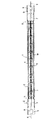
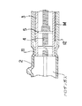
図1は、本発明のヒータランプの構成を示す断面図、図2は後述する図1に示す管型封体と内管との封着状態を示す説明図である。
【0013】
同図において、1は封入ガスに微量のハロゲンガスを添加したハロゲンランプからなるヒータランプ、2は石英ガラスからなる管型封体、3は石英ガラスからなり両端が開口している内管、4は内管3内部に支持部材5に支持され、発熱体としてのタングステン製のフィラメント、6はヒータランプ1の端部に設けられ電源に接続される外部リード棒、7はフィラメント4に接続された内部リード棒、8は内部リード棒7と外部リード棒6に接続され封止部9に埋設された金属箔、10は管型封体に形成された排気管残部である。
【0014】
そして、管型封体2と内管3は、内管3の両端部において、管型封体2の内面と内管3の外面が封着され、封着部11が形成されている。
図2は、図1の管型封体1と内管2が封着された部分の拡大であり、管型封体2の内面が内管3の外面に気密に封着されており、この封着された部分が封着部11になっており、管型封体2内面と内管3外面との間に気密空間12が形成されている。この気密空間12は内管3の内部と管型封体2の外部(外気)と完全に遮断されている。
【0015】
そして、図1、図2に示すように、管型封体2内面と内管3外面との間である気密空間12内に、反射部材である反射板Mが設けられている。
この反射板Mは、図3に示すように、半円樋状の金属製の反射板であり、SUS板の表面に反射率を向上させるために金をコーティングしたものである。なお、反射板は、SUS板以外に、ニッケル等の高融点材料を用いることができ、コート物質も金以外に、ニッケルやセラミック系反射材料を用いることができる。この結果、反射板Mによって光が反射され、ヒータランプ1から特定方向に光が放射されるものである。
【0016】
つまり、反射板Mは、管型封体2内面と内管3外面との間の気密空間12内に配置されており、この気密空間12は内管3の内部と管型封体2の外部(外気)と完全に遮断されているので、反射板Mの表面にコーティングされた金が剥がれても内管3の内部及び管型封体2の外部であるヒータランプの外部に剥がれ落ちたり飛散することがなく、ヒータランプから汚染物質が発生することがない。
【0017】
そらに、反射板Mに水分が含まれていたとしても、この水分は管型封体2の外部であるヒータランプの外部に放出されることがないので、このヒータランプを真空中等の反応容器内で使用することができ、どのような作業環境であっても使用でき、作業環境を悪化させることがない。
【0018】
さらには、気密空間12内を真空にするか窒素等の不活性ガスを封入することにより、反射板Mの酸化が防止され、反射板Mの反射率を長時間維持することができ、ヒータランプから安定した光が長時間放射される。
【0019】
図4は、反射板の固定方法を示す説明であり、ヒータランプの外観形状を示し、図5は、図4におけるA−A矢印方向断面図である。
なお、図5は、フィラメント及びサポータを省略して描いている。
図4、図5に示すように、管型封体2は、反射板Mを挟んで両側に反射板Mの両端から少し離れた位置に、内管3の方向に向かって突起部1aがヒータランプ1の両側に2ヶ所づつ合計4ヶ所形成されている。この突起部1aは、管型封体2の一部を加熱して内方に凹ませたディンプルである。
この結果、反射板Mの動きが突起部1aで規制されることになり、管型封体2と内管3との間で反射板Mが回転せず固定されるので、常に、所定の方向に光を放射することができる。
なお、突起部1aは、ヒータランプ1の片側だけに2ヶ所形成されていてもよく、ヒータランプ1の長手方向中央側だけに2ヶ所形成されていてもよい。
【0020】
図6(イ)(ロ)は、反射板の他の固定方法を示す説明図であり、ヒータランプの管軸に対して垂直方向の断面図である。なお、図6(イ)(ロ)は、フィラメント及びサポータを省略して描いている。そして、図7(イ)(ロ)は、図6(イ)(ロ)に示す反射板と固定部材のみを取り出した一部分の斜視図である。
図6(イ)と図7(イ)に示すように、反射板Mには固定部材であるバネ性のコイル部材K1の一端が溶接によって取り付けられおり、この溶接箇所を図中Pで示す。このコイル部材K1は一端側がフリー状態になっており、内管3から管型封体2に向かって広がろうとする力を有しており、コイル部材K1の一端側近傍の一部が管型封体2の内面に押圧した状態で接している。
この結果、反射板Mが管型封体2と内管3との間で回転せず固定されるので、常に、所定の方向に光を放射することができる。
なお、コイル部材K1は、反射板Mの両側に2つ取り付けられていてもよく、反射板Mの片側だけに1つ取り付けられていてもよく、反射板Mの長手方向中央部分に1つ取り付けられていてもよい。
【0021】
図6(ロ)と図7(ロ)に示すように、反射板Mには固定部材である多角形に折り曲げられた線状部材K2が溶接によって取り付けられており、この溶接箇所を図中Pで示す。この線状部材K2は一端側がフリー状態になっており、折り曲げられた折曲部P1が管型封体2の内面に当接しており、複数の折曲部P1が管型封体2の内面に接触している。
この結果、反射板Mが管型封体2と内管3との間で回転せず固定されるので、常に、所定の方向に光を放射することができる。
なお、線状部材K2は、反射板Mの両側に2つ取り付けられていてもよく、反射板Mの片側だけに1つ取り付けられていてもよく、反射板Mの長手方向中央部分に1つ取り付けられていてもよい。
【0022】
本発明の他の実施例として、図1に示す両側に形成された封着部11の間であって、管型封体2内面の一部分、あるいは、内管3外面の一部分に反射部材である金メッキを施してもよい。
ここで言う一部分とは、管型封体2内面、あるいは内管3外面であって、管軸に沿って光を取り出すための部分を除く領域のことである。
反射部材として、金メッキ以外に、金の蒸着膜であってもよく、反射作用を有する物質のメッキ、蒸着、塗布であってもよい。
このように、管型封体2内面、あるいは、内管3外面に直接反射部材を被着すれば、別途、反射板が不要になり、構造が簡単で、しかも確実に所定の方向に光を放射することができる。
【0023】
【発明の効果】
以上説明したように、請求項1に記載の発明によれば、反射部材自体や、反射部材の表面にコーティングされたコート部材が剥がれても内管の内部及び管型封体の外部であるヒータランプの外部に剥がれ落ちたり飛散することがなく、反射部材に水分が含まれていても、水分がヒータランプの外部に放出されることがなく、よって、ヒータランプから汚染物質が発生することがなく、どのような作業環境であっても使用でき、作業環境を悪化させることがないヒータランプとなる。
【0024】
請求項2に記載の発明によれば、反射部材として、半円樋状の金属製の反射板を用いることにより、簡単な構造の反射部材となる。
【0025】
請求項3に記載の発明によれば、管型封体には、内管方向に向かって突起部が形成されているので、この突起部によって反射板の動きが規制され、反射板が管型封体と内管との間で回転せず確実に固定されるので、常に、所定の方向に光を放射することができる。
【0026】
請求項4に記載の発明によれば、反射板には、管型封体内面に当接して反射板を固定するための固定部材が取り付けられているので、反射板が管型封体と内管との間で回転せず確実に固定されるので、常に、所定の方向に光を放射することができる。
【0027】
請求項5に記載の発明によれば、管型封体内面の一部分、あるいは、前記内管外面の一部分に反射部材が被着されているので、反射板を使用しなくても、簡単な構造で、しかも確実に所定の方向に光を放射することができる。
【図面の簡単な説明】
【図1】本発明のヒータランプの説明図である。
【図2】本発明のヒータランプの管型封体と内管との封着状態を示す説明図である。
【図3】本発明のヒータランプに使用される反射部材の説明図である。
【図4】本発明の反射板の固定方法を示す説明図である。
【図5】図4におけるA−A矢印方向断面である。
【図6】本発明の反射板の固定方法を示す説明図である。
【図7】図6に示す反射板と固定部材のみを示す斜視図である。
【符号の説明】
1 ヒータランプ
2 管型封体
3 内管
4 フィラメント
5 支持部材
6 外部リード棒
7 内部リード棒
8 金属箔
9 封止部
10 排気管残部
11 封着部
1a 突起部
12 気密空間
M 反射板
K1 コイル部材
K2 線状部材
P 溶接箇所
P1 折曲部[0001]
[Technical field to which the invention belongs]
The present invention relates to a heater lamp used for semiconductor heating, glass heating, food heating, or the like.
[0002]
[Prior art]
Conventionally, heater lamps used for semiconductor heating, glass heating, or food heating are those in which a heating element is disposed in a tube-shaped envelope, and an object to be heated is heated by light emitted from the heating element. is there.
In this case, in order to effectively use the light emitted from the heater lamp, the heater lamp is usually covered with a semicircular metal reflector and used as a unitized heater lamp unit.
[0003]
[Problems to be solved by the invention]
However, in such a heater lamp unit, a casing for integrating the heater lamp and the reflecting mirror is necessary, and a mechanism corresponding to the expansion and contraction of the reflecting mirror accompanying the turning on / off of the heater lamp is necessary. There was a problem of becoming complicated.
[0004]
In addition, the reflecting surface of the reflecting mirror is generally coated with gold to increase the reflectance, or various coatings are generally applied, and these coating substances are oxidized to reduce the reflectance. Alternatively, there has been a problem that the coating substance peels off and contaminates the object to be heated.
[0005]
Furthermore, in such a heater lamp unit, moisture may be absorbed by the reflecting mirror and casing, and when used in a reaction vessel such as in a vacuum, there is a problem that moisture evaporates and the working environment is deteriorated.
[0006]
Accordingly, the present invention provides a heater lamp that is simple in structure, emits light efficiently and stably from a single heater lamp, does not generate contaminants from the heater lamp, and does not affect the work environment. is there.
[0007]
[Means for Solving the Problems]
In order to solve the above-described problem, the heater lamp according to
[0008]
The heater lamp according to
[0009]
The heater lamp according to
[0012]
DETAILED DESCRIPTION OF THE INVENTION
Embodiments of the present invention will be specifically described below with reference to the drawings.
FIG. 1 is a cross-sectional view showing a configuration of a heater lamp of the present invention, and FIG. 2 is an explanatory view showing a sealed state between a tube-type sealed body and an inner tube shown in FIG.
[0013]
In the figure, 1 is a heater lamp made of a halogen lamp in which a small amount of halogen gas is added to the sealed gas, 2 is a tubular envelope made of quartz glass, 3 is an inner tube made of quartz glass and open at both ends, 4 Is supported by a
[0014]
The tube-type sealed
FIG. 2 is an enlarged view of a portion where the tube-
[0015]
As shown in FIGS. 1 and 2, a reflecting plate M as a reflecting member is provided in an
As shown in FIG. 3, the reflector M is a semicircular metal reflector, and the surface of the SUS plate is coated with gold in order to improve the reflectance. In addition to the SUS plate, the reflective plate can be made of a high melting point material such as nickel, and the coating material can be made of nickel or a ceramic-based reflective material other than gold. As a result, light is reflected by the reflecting plate M, and light is emitted from the
[0016]
That is, the reflecting plate M is disposed in an
[0017]
In addition, even if moisture is contained in the reflector M, the moisture is not released to the outside of the heater lamp, which is outside the tube-
[0018]
Furthermore, by evacuating the inside of the
[0019]
FIG. 4 is an explanatory view showing a method of fixing the reflecting plate, showing the external shape of the heater lamp, and FIG. 5 is a cross-sectional view in the direction of arrows AA in FIG.
In FIG. 5, the filament and the supporter are omitted.
As shown in FIGS. 4 and 5, the tube-
As a result, the movement of the reflecting plate M is restricted by the
Two
[0020]
6A and 6B are explanatory views showing another fixing method of the reflecting plate, and are sectional views in a direction perpendicular to the tube axis of the heater lamp. In FIGS. 6A and 6B, the filament and the supporter are omitted. FIGS. 7A and 7B are perspective views of a part where only the reflector and the fixing member shown in FIGS. 6A and 6B are taken out.
As shown in FIGS. 6 (a) and 7 (a), one end of a spring-like coil member K1, which is a fixing member, is attached to the reflecting plate M by welding. The coil member K1 has a free state at one end side, and has a force to spread from the
As a result, the reflecting plate M is fixed without rotating between the tube-shaped
Two coil members K1 may be attached to both sides of the reflecting plate M, one may be attached to only one side of the reflecting plate M, or one is attached to the longitudinal center portion of the reflecting plate M. It may be done.
[0021]
As shown in FIGS. 6 (b) and 7 (b), a linear member K2 bent into a polygon, which is a fixing member, is attached to the reflector M by welding. It shows with. One end of the linear member K2 is in a free state, the bent portion P1 is in contact with the inner surface of the
As a result, the reflecting plate M is fixed without rotating between the tube-shaped
In addition, two linear members K2 may be attached to both sides of the reflector M, or may be attached to only one side of the reflector M, and one in the longitudinal center portion of the reflector M. It may be attached.
[0022]
As another embodiment of the present invention, a reflective member is provided between the sealing portions 11 formed on both sides shown in FIG. 1 and a part of the inner surface of the tube-shaped
The part mentioned here is a region excluding a part for taking out light along the tube axis, on the inner surface of the tube-shaped
In addition to gold plating, the reflective member may be a gold vapor deposition film, or may be plating, vapor deposition, and application of a substance having a reflective action.
In this way, if a reflecting member is directly attached to the inner surface of the tube-shaped
[0023]
【The invention's effect】
As described above, according to the first aspect of the present invention, even if the reflecting member itself or the coating member coated on the surface of the reflecting member is peeled off, the heater that is inside the inner tube and outside the tube-type sealed body. Even if the reflecting member does not peel off or scatter and the moisture is contained in the reflecting member, the moisture is not released to the outside of the heater lamp. The heater lamp can be used in any work environment and does not deteriorate the work environment.
[0024]
According to invention of
[0025]
According to the third aspect of the present invention, since the protruding portion is formed in the tube-shaped envelope toward the inner tube direction, the movement of the reflecting plate is restricted by the protruding portion, and the reflecting plate is tube-shaped. Since it is securely fixed without rotating between the envelope and the inner tube, light can always be emitted in a predetermined direction.
[0026]
According to the fourth aspect of the invention, the reflecting plate is provided with a fixing member for fixing the reflecting plate in contact with the inner surface of the tube-shaped sealing body. Since it is securely fixed without rotating between the tubes, light can always be emitted in a predetermined direction.
[0027]
According to the fifth aspect of the present invention, since the reflecting member is attached to a part of the inner surface of the tube-type sealing body or a part of the outer surface of the inner tube, a simple structure can be obtained without using a reflecting plate. In addition, it is possible to reliably emit light in a predetermined direction.
[Brief description of the drawings]
FIG. 1 is an explanatory diagram of a heater lamp according to the present invention.
FIG. 2 is an explanatory view showing a sealed state between the tube-type sealed body and the inner tube of the heater lamp of the present invention.
FIG. 3 is an explanatory diagram of a reflecting member used in the heater lamp of the present invention.
FIG. 4 is an explanatory view showing a method of fixing a reflector according to the present invention.
5 is a cross-sectional view taken along the line AA in FIG.
FIG. 6 is an explanatory view showing a method of fixing a reflector according to the present invention.
7 is a perspective view showing only the reflector and the fixing member shown in FIG. 6. FIG.
[Explanation of symbols]
DESCRIPTION OF
Claims (3)
前記管型封体内に、前記発熱体を覆うように形成するとともに、両端部において外面が前記管型封体内面に封着された筒状の内管を配置し、
前記封着された前記管型封体内面と前記内管外面との間に、半円樋状の金属製の反射板が設けられ、
前記管型封体には、前記反射板を挟んで両側に反射板の両端から少し離れた位置に、前記内管方向に向かって突起部が設けられていることを特徴とするヒータランプ。In the heater lamp in which the heating element is arranged along the tube axis inside the tube-shaped envelope,
The tubular envelope is formed so as to cover the heating element, and at both ends, a cylindrical inner tube having an outer surface sealed to the inner surface of the tubular envelope is disposed.
Between the sealed inner surface of the tube-shaped envelope and the outer surface of the inner tube, a semicircular bowl-shaped metal reflector is provided ,
The heater lamp according to claim 1, wherein the tube-shaped sealed body is provided with protrusions toward the inner tube at positions slightly apart from both ends of the reflector on both sides of the reflector .
前記管型封体内に、前記発熱体を覆うように形成するとともに、両端部において外面が前記管型封体内面に封着された筒状の内管を配置し、
前記封着された前記管型封体内面と前記内管外面との間に、半円樋状の金属製の反射板が設けられ、
前記反射板には、前記管型封体内面に当接して当該反射板を固定するために、バネ性のコイル部材の一端が溶接により取り付けられていることを特徴とするヒータランプ。 In the heater lamp in which the heating element is arranged along the tube axis inside the tube-shaped envelope,
The tubular envelope is formed so as to cover the heating element, and at both ends, a cylindrical inner tube having an outer surface sealed to the inner surface of the tubular envelope is disposed.
Between the sealed inner surface of the tube-shaped envelope and the outer surface of the inner tube, a semicircular bowl-shaped metal reflector is provided,
Wherein the reflecting plate, for abutting on the tubular sealing body surface fixing the reflection plate, the heater lamp one end of the spring of the coil member is characterized that you have attached by welding.
前記管型封体内に、前記発熱体を覆うように形成するとともに、両端部において外面が前記管型封体内面に封着された筒状の内管を配置し、
前記封着された前記管型封体内面と前記内管外面との間に、半円樋状の金属製の反射板が設けられ、
前記反射板には、前記管型封体内面に当接して当該反射板を固定するために、多角形に折り曲げられた線状部材が溶接により取り付けられていることを特徴とするヒータランプ。 In the heater lamp in which the heating element is arranged along the tube axis inside the tube-shaped envelope,
The tubular envelope is formed so as to cover the heating element, and at both ends, a cylindrical inner tube having an outer surface sealed to the inner surface of the tubular envelope is disposed.
Between the sealed inner surface of the tube-shaped envelope and the outer surface of the inner tube, a semicircular bowl-shaped metal reflector is provided,
Wherein the reflection plate, the heater lamp, characterized in that to secure the reflector in contact with the tubular sealing body surface, a linear member that is bent in a polygon are attached, et al by welding.
Priority Applications (1)
| Application Number | Priority Date | Filing Date | Title |
|---|---|---|---|
| JP2000231786A JP3832206B2 (en) | 2000-07-31 | 2000-07-31 | Heater lamp |
Applications Claiming Priority (1)
| Application Number | Priority Date | Filing Date | Title |
|---|---|---|---|
| JP2000231786A JP3832206B2 (en) | 2000-07-31 | 2000-07-31 | Heater lamp |
Publications (2)
| Publication Number | Publication Date |
|---|---|
| JP2002043037A JP2002043037A (en) | 2002-02-08 |
| JP3832206B2 true JP3832206B2 (en) | 2006-10-11 |
Family
ID=18724565
Family Applications (1)
| Application Number | Title | Priority Date | Filing Date |
|---|---|---|---|
| JP2000231786A Expired - Fee Related JP3832206B2 (en) | 2000-07-31 | 2000-07-31 | Heater lamp |
Country Status (1)
| Country | Link |
|---|---|
| JP (1) | JP3832206B2 (en) |
Families Citing this family (12)
| Publication number | Priority date | Publication date | Assignee | Title |
|---|---|---|---|---|
| JP2002134430A (en) * | 2000-10-24 | 2002-05-10 | Tokyo Electron Ltd | Lamp with high-reflectivity film for enhancing directivity and heat treating apparatus |
| KR100767851B1 (en) * | 2005-07-14 | 2007-10-18 | 엘지전자 주식회사 | Structure of heating body |
| US7747147B2 (en) | 2005-11-02 | 2010-06-29 | Panasonic Corporation | Heating unit and heating apparatus |
| JP4939961B2 (en) * | 2006-09-11 | 2012-05-30 | メトロ電気工業株式会社 | Infrared heater |
| JP2008097897A (en) * | 2006-10-10 | 2008-04-24 | Matsushita Electric Ind Co Ltd | Heating element unit and heating device |
| JP2009213595A (en) * | 2008-03-10 | 2009-09-24 | Maruzen Co Ltd | Grilling apparatus |
| KR101450895B1 (en) * | 2008-03-17 | 2014-10-21 | 엘지전자 주식회사 | Filament supporter and tube heater comprising the same |
| JP2010112586A (en) * | 2008-11-04 | 2010-05-20 | Mitsubishi Electric Corp | Heating cooker |
| JP5001247B2 (en) * | 2008-11-05 | 2012-08-15 | 三菱電機株式会社 | Cooker |
| FR2944345B1 (en) * | 2009-04-08 | 2013-03-22 | Saint Gobain | OVEN COMPRISING A THERMAL BARRIER |
| CN202949578U (en) * | 2012-11-19 | 2013-05-22 | 李文庆 | Heating device |
| US20180338350A1 (en) * | 2017-05-19 | 2018-11-22 | Lg Electronics Inc. | Carbon heater |
-
2000
- 2000-07-31 JP JP2000231786A patent/JP3832206B2/en not_active Expired - Fee Related
Also Published As
| Publication number | Publication date |
|---|---|
| JP2002043037A (en) | 2002-02-08 |
Similar Documents
| Publication | Publication Date | Title |
|---|---|---|
| JP3832206B2 (en) | Heater lamp | |
| JPS59180958A (en) | Infrared ray lamp | |
| JP2006024566A (en) | Halogen incandescent lamp | |
| JP2008513944A (en) | Lamp assembly comprising a lamp and a reflector | |
| JP5410986B2 (en) | Electric reflection lamp | |
| EP0434292A2 (en) | Vibration resistant mount structure for double ended tungsten-halogen lamp | |
| JP3858543B2 (en) | Heater lamp | |
| US20060181207A1 (en) | Electric incandescent lamp with infrared reflecting layer | |
| JP2007536716A (en) | Incandescent filament for incandescent lamp and incandescent lamp | |
| JP3552488B2 (en) | Electrodeless discharge lamp | |
| JPH0475204A (en) | Bulb type fluorescent lamp device | |
| JP2774428B2 (en) | Discharge lamp device | |
| JPH0479145A (en) | Discharge lamp apparatus | |
| JP4173077B2 (en) | Reflector built-in lamp | |
| JP4442511B2 (en) | Lamp device | |
| JPH11339731A (en) | Electric bulb, reflex electric bulb and luminaire | |
| JPH11287460A (en) | Heating cooker | |
| JP4373875B2 (en) | Reflector integrated short arc lamp | |
| JP2003168303A (en) | Discharge lamp device | |
| JP4087313B2 (en) | Light source device | |
| JP3674078B2 (en) | Incandescent light bulb and reflective lighting device | |
| JPH083954Y2 (en) | Small metal vapor discharge lamp | |
| JP3712080B2 (en) | Light bulb and lighting equipment | |
| JP2005276456A (en) | Compact self-ballasted fluorescent lamp and luminaire | |
| JP3888298B2 (en) | Excimer lamp device |
Legal Events
| Date | Code | Title | Description |
|---|---|---|---|
| A977 | Report on retrieval |
Free format text: JAPANESE INTERMEDIATE CODE: A971007 Effective date: 20051201 |
|
| A131 | Notification of reasons for refusal |
Free format text: JAPANESE INTERMEDIATE CODE: A131 Effective date: 20060131 |
|
| A521 | Written amendment |
Free format text: JAPANESE INTERMEDIATE CODE: A523 Effective date: 20060317 |
|
| TRDD | Decision of grant or rejection written | ||
| A01 | Written decision to grant a patent or to grant a registration (utility model) |
Free format text: JAPANESE INTERMEDIATE CODE: A01 Effective date: 20060627 |
|
| A61 | First payment of annual fees (during grant procedure) |
Free format text: JAPANESE INTERMEDIATE CODE: A61 Effective date: 20060710 |
|
| R150 | Certificate of patent or registration of utility model |
Free format text: JAPANESE INTERMEDIATE CODE: R150 |
|
| FPAY | Renewal fee payment (event date is renewal date of database) |
Free format text: PAYMENT UNTIL: 20100728 Year of fee payment: 4 |
|
| FPAY | Renewal fee payment (event date is renewal date of database) |
Free format text: PAYMENT UNTIL: 20110728 Year of fee payment: 5 |
|
| FPAY | Renewal fee payment (event date is renewal date of database) |
Free format text: PAYMENT UNTIL: 20120728 Year of fee payment: 6 |
|
| FPAY | Renewal fee payment (event date is renewal date of database) |
Free format text: PAYMENT UNTIL: 20130728 Year of fee payment: 7 |
|
| LAPS | Cancellation because of no payment of annual fees |