JP3830836B2 - Automatic analyzer - Google Patents
Automatic analyzer Download PDFInfo
- Publication number
- JP3830836B2 JP3830836B2 JP2002062277A JP2002062277A JP3830836B2 JP 3830836 B2 JP3830836 B2 JP 3830836B2 JP 2002062277 A JP2002062277 A JP 2002062277A JP 2002062277 A JP2002062277 A JP 2002062277A JP 3830836 B2 JP3830836 B2 JP 3830836B2
- Authority
- JP
- Japan
- Prior art keywords
- reagent
- sample
- disk
- rack
- automatic analyzer
- Prior art date
- Legal status (The legal status is an assumption and is not a legal conclusion. Google has not performed a legal analysis and makes no representation as to the accuracy of the status listed.)
- Expired - Lifetime
Links
Images


Description
【0001】
【発明の属する技術分野】
本発明は、自動分析装置に係り、特に、血液、尿の成分等の定量分析を比色分析により行う臨床用生化学分析に使用して好適な自動分析装置に関する。
【0002】
【従来の技術】
臨床用生化学分析に使用する自動分析に関する従来技術として、例えば、ディスクリート方式とよばれる方法が知られている。
【0003】
図9は従来技術によるディスクリート方式の自動分析装置の構成を示すブロック図であり、以下、図9を参照して、従来技術による自動分析装置について説明する。図9において、901はサンプルディスク、902は反応ディスク、903は試薬ディスク、904は血清サンプリング機構、905は試薬ピペッティング機構、906は洗浄機構、907は多波長光度計、908は血清用ピペッタ制御部、909は洗浄水ポンプ、910は試薬用ピペッタ制御部、911はマイクロコンピュータ、912はプリンタ、913はディスプレイ装置、914は外部記憶装置、915はインタフェース、916は操作パネル、917は恒温槽である。
【0004】
従来技術による自動分析装置は、図9に示すように、血清サンプル等の試料を多数保持するサンプルディスク901と、複数種の試薬を保持する試薬ディスク903と、複数の反応セルを有する反応ディスク902とを備えて構成されている。そして、サンプルディスク901上の試料は、血清用ピペッタ制御部908により制御される血清サンプリング機構904により吸引計量されて、反応ディスク902上の反応セル内に吐出され、試薬ディスク903上の必要な試薬が、試薬用ピペッタ制御部910により制御される試薬ピペッティング機構905により吸引計量され、試薬が入れられ反応セル内に吐出される。反応セル内の混合液は、恒温槽917により一定温度に加熱されながら反応が進み発色する。
【0005】
発色した反応セル内の混合液は、多波長光度計907により、一定時間後または一定時間間隔で比色分析される。この分析結果は、マイクロコンピュータ911に送られ、目的成分の濃度等に変換され、ディスプレイ装置913に表示されると共に、プリンタ912に出力され、また、必要により、フレキシブルディスク装置等の外部記憶装置914に記憶される。
【0006】
測定後、反応セルは、洗浄機構906により洗浄水ポンプ909からの洗浄水で洗浄される。また、試料の分析のために第2、第3の試薬が必要な場合、試薬ピペッティング機構905により適宜試料が分注されている反応セルにそれらの試薬が分注される。
【0007】
前述した測定の処理は、操作者による操作パネル916からの指示に基づいて、マイクロコンピュータ911の制御の下に自動的に行うことができる。
【0008】
なお、前述した従来技術による自動分析装置に設けられたサンプルディスク901、試薬ディスク903、反応ディスク902、血清サンプリング機構904、試薬ピペッティング機構905は、筐体の上面に露出して設けられることが多く、それらを1枚の開閉式の蓋で覆うか、あるいは、それぞれを独立した蓋で覆うようにしているのが一般的である。
【0009】
また、従来技術による自動分析装置において、試薬ディスク903への試薬の投入は、定められた位置に定められた試薬を作業者の手で投入することが必要である。さらに、試薬は、通常、一日に使用される量を試薬ディスク903に収納できることが好ましく、そのため、試薬ディスク903は、大きな径とするか、あるいは、複数個の試薬ディスクを備える必要がある。
【0010】
【発明が解決しようとする課題】
前述した従来技術による自動分析装置は、試料を保持している検体の投入、試薬の投入をも含めた全ての処理を自動化すること、緊急に分析すべき試料を割り込ませることについての配慮がなされておらず、装置全体の使い勝手がよくないという問題点を有している。
【0011】
本発明の目的は、前述した従来技術の問題点を解決し、試料を保持している検体の投入、試薬の投入をも含めた全ての処理を自動化し、緊急に分析すべき試料の割り込みを容易に行うことを可能にした使い勝手のよい自動分析装置を提供することにある。
【0012】
【課題を解決するための手段】
本発明に係る自動分析装置は、前記目的を達成するために、自動分析装置の上面を、反応セルを保持する反応ディスクが配置された反応ディスクエリアと、試薬ラックを保持する試薬ディスクが配置された試薬ディスクエリアとに分け、前記試薬ディスクエリアの試薬ディスクの上方に、前記試薬ラックを前記試薬ディスクへ投入する投入機構を備え、前記反応ディスクエリアには、その上面を覆う第1の開閉蓋が開放可能に取り付けられ、前記試薬ディスクエリアには、前記投入機構を含む上面を覆う第2の開閉蓋が装置上面に仮止めされて取り付けられ、装置側面には、試薬ラック投入口が設けられると共に、この試薬ラック投入口を覆うように開閉可能に取り付けられる試薬トレーを備えたことを特徴とする。
【0014】
【発明の実施の形態】
以下、本発明による自動分析装置の実施形態を図面により詳細に説明する。
【0015】
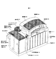
図1は本発明の一実施形態による自動分析装置の外観を示す斜視図、図2は本発明の位置実施形態による自動分析装置の使用状態での外観及び作業棚上面の状態を説明する図、図3はユーザ側の開閉蓋を開いた状態を示す斜視図、図4は自動分析装置の上面における機器の配置を説明する上面図、図5は自動分析装置の上面における機器の配置を説明する斜視図である。図1〜図5において、101は台座部、102は本体部筐体、103は検体投入部筐体、104、105は開閉蓋、106、107、206は透明窓、108は割り込み用検体投入部、109は投入溝、110は検体投入部用透明カバー、111はバッファディスク用透明カバー、112はISE(滲透圧利用の検査試薬)交換スペース、113はISE試薬容器、114は試薬トレー、115、116は取っ手、201は試薬ラック、202は傾斜部、203は案内溝、204はバーコード読み取り部、205は試薬ラック投入口、301は反応ディスク、302は反応セル、303は検体溝、304、305、410、411は分注器、306、307、501、502はピペット、308はセルクリーナ、309、310は分注器支柱、401は検体ラック投入領域、402は検体ラック回収領域、403は検体ラック、404は検体容器、405はバッファディスク、406は試薬ディスク、407は分注器用フレーム、408、409は分注器用スライドフレーム、412は試薬ラック排出穴、413、414はピペット洗浄液保持部である。
【0016】
本発明の一実施形態による自動分析装置は、装置を使用していない状態で図1に示すような外観を有しており、台座部101上に本体部筐体102と検体投入部筐体103とが載置されて構成される。本体部筐体102は、その内部に、分析装置を構成する各機器を駆動するための電源、制御機構、恒温槽、洗浄ポンプ等が備えており、また、検体投入部筐体103の内部には、投入された検体ラックを搬送する搬送機構、その制御機構、電源等が備えられているが、これらは、本発明の構成として重要なものではなく、従来技術の場合にも備えられるものであるので、その説明を省略する。
【0017】
本体部筐体102の上面には、後述するように、分析用の各種の機器が配置されており、装置の不使用時、開閉蓋104、105により覆われている。これらの開閉蓋104、105には、内部の状態が見えるように、透明窓106、107が設けられている。そして、開閉蓋104が覆う位置の本体部筐体102の上面には、通常の使用でユーザが触れることが好ましくない後述する試薬ディスクが備えられている。このため開閉蓋104は、通常の使用で開くことができないように、ねじ等により本体部筐体102の上面に固定されており、サービスマンによってのみ開くことができる。すなわち、この開閉蓋104に覆われる本体部筐体102の上面がサービスマンアクセスエリアとなる。また、開閉蓋105が覆う位置の本体部筐体102の上面には、通常の保守点検、清掃等を必要とする後述の反応セルが配置された反応ディスク等が配置されている。この開閉蓋105は、その側面に取っ手116が設けられ、開閉蓋104、105の上面の連結部に設けられるヒンジ等により、図の左側を上方に持ち上げて開くことができる。すなわち、この開閉蓋105に覆われる本体部筐体102の上面がユーザアクセスエリアとなる。
【0018】
開閉蓋105は、横からの動作で開閉することが可能であり、蓋の開閉作業を少ない負担で行うことができる。また、開閉蓋104は、すでに説明したように、図示しない止め金具、例えば、ねじ等により固定されて、容易に開閉することができないようにされており、分析作業を行う者に触れられたくない試薬ディスク406、その上面に形成された分注用フレーム407等を覆っている。
【0019】
試薬トレー114は、装置使用時には、その上面が水平になるように、取っ手115を用いて手前側に倒すことができるように構成されている。図1では、装置の不使用時の状態を示しているとしているので、試薬トレー114は、開閉蓋104、105の側面を覆うように閉じられている。
【0020】
検体投入部筐体103の上面は、投入された検体と処理が終了した検体とを搬送する搬送路を構成しており、投入された検体を覆うように検体投入部用透明カバー110が設けられている。検体投入部用透明カバー110は、検体の投入時及び処理済みの検体の取り出し時にだけ取り外される。また、検体投入部筐体103の側面には、緊急に分析を行うべき検体を割り込ませて投入するための投入溝109を有する割り込み用検体投入部108が検体投入部筐体103の側面から突出するように設けられている。
【0021】
本体部筐体102と検体投入部筐体103との間には、検体投入部筐体103の上端からの一部が切り欠かれて、ISE交換スペース112が形成されており、このスペースを使用して、滲透圧利用の検査試薬が格納されているISE試薬容器113を本体部筐体102の上面に挿入し、あるいは、取り出すことができる。また、本体部筐体102の奥側の検体投入部筐体103に接する位置には、後述するように、検体投入部からの検体を受け取り、その検体の送り出しの順序を任意に制御することができるバッファディスクが設置されており、ここにも、バッファディスク用透明カバー111が被せられている。
【0022】
さて、前述したような外観を備えて構成され本発明の実施形態による自動分析装置は、使用時、図2(a)に示すように、試薬トレー114が取っ手115を用いて手前にその上面が水平になるように倒されて使用される。試薬トレー114が手前に倒した状態を示す図2(a)から判るように、前述で説明した開閉蓋104の側面には、試薬トレー114が閉じられる位置から下部に透明窓206が設けられている。また、開閉蓋105の対応する側面は、開いたままの状態にされている。試薬トレー114は、本体部筐体102の上面より下方の側面にヒンジ等により、開いたときに水平になる位置で固定されるように取り付けられている。本体部筐体102の上面から試薬トレー114の上面までの高さは、試薬ラック201の高さよりも僅かに大きくなるように設定されており、本体部筐体102の上面から試薬トレー114の上面までの間の側面に試薬ラック投入口205が設けられている。このため、試薬トレー114が閉じられたときには、試薬ラック投入口205は塞がれることになる。
【0023】
試薬トレー114の上面には、図2(b)に示すように、試薬ラック201を装置内部に挿入するための周辺に傾斜部202が設けられた案内溝203が前述した試薬ラック投入口205に繋がるように設けられている。作業者は、作業に先立って、試薬をセットする必要があり、試薬トレー114上に載置された試薬ラック201を滑らせて傾斜部202から案内溝203に落とし込んだ後、装置内部に押し込むことにより、試薬ラック201を内部にセットすることができる。本体部筐体102上面には、試薬ラックを受け入れる溝が設けられており、その溝の側面には、試薬ラック201の側面に記録されているバーコードを読み取るバーコード読み取り部204が設けられている。内部に挿入された試薬ラック201は、バーコードの読み取り結果により、後述するように、試薬ディスク上の所定の位置にセットされる。作業者は、前述した透明窓206から試薬ラック201が試薬ディスク上の所定の位置にセットされる動作を監視することができる。
【0024】
なお、試薬トレー114は、試薬ラック201を挿入する際の作業テーブルとして利用することができ、さらに、未使用時には開閉蓋104及び105と共に装置の上面を覆う蓋の一部としての機能を備えている。
【0025】
また、従来の自動分析装置においては試薬ラックの投入が、作業者の手で定められた試薬ラックを定められた試薬ディスクの挿入位置に挿入しなければならないため、作業者に対して作業の正確さが求められ煩わしさを与えていたが、本発明の実施形態によれば、試薬ディスクへの試薬ラックの投入が自動化されるため、作業者の単純な作業だけで誤りなく試薬ラックを定められた試薬ディスクの挿入位置にセットすることができる。
【0026】
このため、一日に必要とする試薬が試薬ディスク上にセットされない状態で分析作業が行われ、途中で試薬ディスク上の試薬が不足する状態になっても、作業者は、容易に試薬の補給を行うことができ、試薬ディスクを大きくしたり、複数の試薬ディスクを設ける必要をなくすことができ、自動分析装置の小型化を図ることができる。
【0027】
試薬ラック201は、内部に3つの容器を備えて構成され、これらの容器に異なる種類の試薬を収納しておくことが可能である。試薬の種類によっては、同一の試薬を2つの容器に収納してよく、何れかの試薬が無くなったときには、試薬ラック201全体が交換される。収納している試薬の種類、その組み合わせ等の試薬に関する情報は、前述で説明した図示しないバーコードに記述されて、試薬ラック201の側面に貼付されている。
【0028】
次に、開閉蓋105を上方に開いた状態で本体部筐体102の上面に露出する機器の配置状態について図3を参照して説明する。
【0029】
図3から判るように、この状態で露出するのは、多数の反応セル302がその周辺に配置された反応ディスク301、それぞれがピペット306、307を有する2つの2つの分注器304、305、検体溝303、セルクリーナ308及びISE試薬容器113である。多数の反応セル302には、分注器304により検体溝303に運ばれてきた検体から必要量の検体が注入され、また、必要であれば、分注器305によりISE試薬が分注される。反応セル302には、他の1または複数の試薬も分注されて検体と混合され、装置内部において、従来技術の場合と同様に、一定温度に加熱される。これにより発色した反応セル302内の混合液は、多波長光度計により、一定時間後または一定時間間隔で比色分析される。
【0030】
反応ディスク301は、図示しないマイコン等によって回転制御され、目的の反応セル302を前述した2つの分注器304、305のピペット306、307の位置に位置決めし、その位置で必要な検体、試薬の分注を可能にする。セルクリーナ308は、処理が終了した反応セル302内の検体と試薬との混合液を廃棄し洗浄するために使用される。このセルクリーナ308は、一定期間使用したらそれ自身を洗浄する必要があり、開閉蓋105が図3に示すように開くようにされているのは、このような保守を行うためである。
【0031】
図3ではISE試薬容器113が複数セット可能であること及びその形状も示されている。ISE試薬容器113の数、その形状は本発明において重要なものではない。しかし、それぞれのISE試薬容器113は、その上部に設けられる開口部の位置が容器がセットされる位置によって異なるようにセッティングされる必要がある。すなわち、分注器305のピペット307は、分注器305を支持するする分注器支柱310を中心にした円弧状に動いて試薬を吸引することになるので、各ISE試薬容器113は、その開口部がこの円弧の位置に沿って並ぶようにセットされる。
【0032】
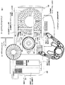
次に、本発明の実施形態による自動分析装置の上面における機器の配置と、検体分析時の検体の動きについて図4、図5を参照して説明する。図4、図5に示す状態は、本体部筐体102及び検体投入部筐体103を覆っている開閉蓋104、105を外し、また、検体投入部用透明カバー110、バッファディスク用透明カバー111も外した状態でのものである。
【0033】
検体投入部筐体103の上面には、搬送機能を有する検体ラック投入領域401と検体ラック回収領域402とが形成されており、検体ラック投入領域401に分析すべき血清サンプル等が収納された複数の検体容器を保持する検体ラック403が投入される。また、分析処理が終了した検体ラック403は検体ラック回収領域402から回収される。検体ラック403は、試験管状に形成された複数(本発明の実施形態では5本)の検体容器404を保持することができ、各検体の内容を示すラベルが貼付されて搬送が制御される。
【0034】
本体部筐体102の上面の検体投入部筐体103側には、すでに説明したように、バッファディスク405及び多数の反応セル302を有する反応ディスク301が配置されている。そして、反応ディスク301の奥側及び手前側に、検体を反応セル302に分注する分注器304とISE試薬を分注する分注器305とが配置されている。分注器304、305は、図5からも判るように、分注器支柱支柱309、310に回動可能かつ上下動可能に支持されており、これにより、それぞれに設けられるピペット306、307を検体、ISE試薬の位置に位置付けてそれらを吸引し、その後に、反応セル302の位置に位置付けて検体、ISE試薬を反応セル302内に排出することができる。
【0035】
また、本体部筐体102の上面の検体投入部筐体103から遠い側の反応ディスク301に隣接する位置には試薬ディスク406が配置されている。試薬ディスク406は、同心円状に2列に試薬ラック201を載置可能に構成されており、後述で詳細に説明するように、試薬トレー114から挿入された試薬ラック201が所定の位置に搭載される。また、複数の試薬容器を持つ試薬ラック201は、試薬ラック201内の試薬が1つでも空となった場合、試薬ラック排出穴412の位置まで運搬されて排出される。
【0036】
前述の試薬ディスク406の上部には、E字型に3本のアームを持って形成された分注器用フレーム407が脚部503を介して、本体部筐体102の上面に固定されて設けられており、2つのアーム相互間に、分注器410、411を備えた分注器用スライドアーム408、409が設けられている。これらの分注器用スライドアーム408、409は、分注器用フレーム407を構成するアームの長手方向に移動制御可能とされており、また、分注器410、411は、分注器用スライドアーム408、409の長手方向及び垂直方向に移動制御可能とされている。前述したように移動制御される分注器410、411は、マイコン等による指示に基づいて、それぞれが持つピペット501、502により、所定の試薬ラック201内の所定の試薬を、所定の反応セル302に分注することができる。
【0037】
次に、検体の投入から分析処理検体の回収までの処理動作について説明する。
【0038】
検体は、検体容器404に入れられており、そり複数が検体ラック403に保持されて検体ラック投入領域401に投入される。その際、複数の検体ラック403を投入することが可能である。分析処理が開始されると、各検体ラック403は、順に複数の検体ラック403を収納可能なバッファディスク405に送り込まれる。また、緊急に検査をすべき検体を保持する検体ラックは、任意のときに割り込み用検体投入部108から投入されてバッファディスク405に送り込まれる。
【0039】
バッファディスク405は、制御されて時計方向、反時計方向のどちらの方向にも回転可能であり、バッファディスク405内の検体ラック201は、分注位置となる検体溝303に送り込まれる。このとき、バッファディスク405は、前述のように回転制御されることにより、バッファディスク405内の検体ラックを、バッファディスク405に投入された順序とは異なる順序で検体溝303に送り込むことができる。これにより、緊急に検査をすべき検体を保持する検体ラックが投入された場合にも、その検体ラックを直ちに分注位置となる検体溝303に送り込むことが可能になる。
【0040】
検体ラック403の1つが検体溝303に送り込まれると、分注器304は、各検体容器404内の検体を反応セル302に分注する。その際、分析項目によっては、同一の検体が複数の反応セル302に分注される。また、分注器304は、異なる検体容器404の検体を分注する毎に、周知のように、そのピペットの洗浄が行われる。そして、検体が分注された反応セル302のそれぞれには、必要な試薬が、分注器305、410、411により分注されて検体と混合される。前述の検体及び試薬の分注の際、反応ディスク301は、その回転が制御され、また、各分注器305、410、411の動きが制御されて、反応セル302の位置と各分注器のピペットの位置とが一致するように対応付けられる。
【0041】
反応セル302内の検体と試薬との混合液を使用する検体の分析処理は、従来技術で説明したと同様に行われ、処理が終了した反応セル302は、セルクリーナ308により内部の混合液が廃棄されて洗浄されて次の分析処理のために使用可能とされる。
【0042】
一方、反応セル302への検体の分注が済んだ検体ラック403は、検体溝303からバッファディスク405を介して検体投入部筐体103の上面の検体ラック回収領域402に戻される。この戻された検体ラック403は、分析結果の正常性が確認される迄、冷蔵庫等に保管され、その後廃棄される。
【0043】
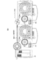
図6は分注機構の詳細を示す斜視図、図7は試薬ラック運搬機構の詳細を示す斜視図である。図6、図7において、601は分注器駆動部、701は吊り下げ器駆動部、702は試薬ラック吊り下げ器、703は吊り下げ爪、704は爪掛け穴であり、他の符号は図4の場合と同一である。
【0044】
図4、図5において、分注器410、411は、分注器用スライドフレーム408、409に取り付けられるとしたが、詳細には図6に示すように、分注器用スライドフレーム408、409に取り付けられている分注器駆動部601、602に取り付けられている。分注器駆動部601、602は、分注器用スライドフレーム408、409の長手方向に移動制御され、分注器410、411を上下方向に駆動制御すると共に、所定量の試薬を吸引、排出制御するものであり、これにより分注器410、411に取り付けられているピペット501、502を試薬容器内に差し込んで試薬を吸引し、反応セル302の位置で排出することができる。なお、ピペット501、502は、試薬の分注を行った都度、ピペット洗浄液保持部413、414の位置で洗浄される。
【0045】
試薬ラック運搬機構は、図7(a)に示すように、分注器用スライドフレーム409に取り付けられている分注器駆動部602の背面に設けられる吊り下げ器駆動部701と、これに取り付けられている試薬ラック吊り下げ器702とによって構成されている。そして、試薬ラック吊り下げ器702は、分注器411の場合と同様に、分注器用スライドフレーム409の移動と吊り下げ器駆動部701の移動とにより、分注器用フレーム407の2本のアームにより形成される領域内の任意の位置に移動可能とされ、また、吊り下げ器駆動部701により上下に移動可能とされている。そして、試薬ラック吊り下げ器702は、図7(b)に示すように、その下部に4本の吊り下げ爪703が備えられ、試薬ラック201には、4本の吊り下げ爪703に対応する位置に爪掛け穴704が設けられている。
【0046】
試薬ラック運搬機構は、前述のように構成されているので、試薬ラック201が試薬トレー114から装置内部に挿入されたとき、挿入された試薬ラック201の位置に試薬ラック運搬機構を位置付けることができる。そして、試薬ラック吊り下げ器702を下方に駆動すると、試薬ラック吊り下げ器702に設けられる4本の吊り下げ爪703が試薬ラック201の爪掛け穴704に挿入される。この状態で、吊り下げ爪703を外方向に広げると、試薬ラック201は、試薬ラック吊り下げ器702に設けられる4本の吊り下げ爪703に系合する。
【0047】
試薬ラック201を4本の吊り下げ爪703に系合させた後、試薬ラック吊り下げ器702を上方に駆動して試薬ラック201を持ち上げ、分注器用フレーム407の2本のアームにより形成される領域内を移動させると共に、試薬ディスク406を回転させて、試薬ラック201をセットすべき試薬ディスク406の位置に位置付ける。そして、試薬ラック吊り下げ器702を下方に駆動して試薬ラック201を試薬ディスク406上に乗せた後、吊り下げ爪703の系合を解くことにより、試薬ラック201を試薬ディスク406上にセットすることができる。内部の試薬が無くなった試薬ラック201は、前述と逆に、試薬ラック排出穴412の位置まで運搬されて排出される。
【0048】
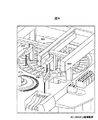
図8は本発明の他の実施形態による自動分析装置の上面における機器の配置を説明する上面図である。図8において、801は検体ラック搬送路、802はバッファディスク、803は本体部筐体である。
【0049】
前述までに説明した本発明の実施形態は、1台の検体投入部筐体103と分析処理部を構成する1台の本体部筐体102とにより構成されるとして説明したが、本発明は、1台の検体投入部筐体に分析処理部としての複数台の本体部筐体を結合して構成することができる。
【0050】
図8に示す本発明の他の実施形態は、1台の検体投入部筐体に分析処理部としての本体部筐体を2台結合して構成した例であり、検体投入部筐体103に隣接して設けられる本体部筐体102、これに連結されるもう1つの本体部筐体803は、前述迄に説明した本体部筐体102と基本的に同様に構成されればよい。そして、図8に示す実施形態において、本体部筐体102の上面の奥側には、バッファディスク405から送り出される検体ラック403を本体部筐体803に搬送する検体ラック搬送路801が設けられており、また、本体部筐体803の上面には、検体ラック搬送路801からの検体ラック403を受け取ることができるようにバッファディスク802が設けられている。このバッファディスク802は、図からも判るように、バッファディスク405よりも小型に構成されていてよい。
【0051】
前述のように構成される本発明の他の実施形態において、分析処理が開始されて、検体ラック403が複数の検体ラック403を収納可能なバッファディスク405に送り込まれると、検体ラック403は、バッファディスク405により、本体部筐体803に構成される分析処理部への検体ラック搬送路801または本体部筐体102に構成される分析処理部への検体溝303に振り分けられて送出される。検体ラック搬送路801に送出された検体ラック403は、本体部筐体803のバッファディスク802に送り込まれ、その後、本体部筐体803の検体溝に送出される。そして、前述で説明したと同様に、検体ラック403に収納されている検体の分析が行われる。その際、複数の検体ラック403がバッファディスク802に送り込まれてもよく、バッファディスク802は、それらの検体ラック403の検体溝への送り出し順序を変更することができる。
【0052】
前述では、1台の検体投入部筐体に分析処理部としての本体部筐体を2台結合したとして説明したが、本発明は、1台の検体投入部筐体に分析処理部としての本体部筐体をさらに多数結合して構成することができる。その場合、最後の分析処理部としての本体部筐体以外のものに検体ラック搬送路を設ければよい。
【0053】
前述した本発明の実施形態によれば、試料を保持している検体の投入、試薬の投入をも含めた全ての処理を自動化し、緊急に分析すべき試料の割り込みを容易に行うことを可能にした使い勝手のよい、血液、尿の成分等の定量分析を比色分析により行う臨床用生化学分析に使用して好適な自動分析装置を提供することができる。
【0054】
【発明の効果】
以上説明したように本発明によれば、試料を保持している検体の投入、試薬の投入をも含めた全ての処理を自動化し、緊急に分析すべき試料の割り込みを容易に行うことを可能にした使い勝手のよい自動分析装置を提供することができる。
【図面の簡単な説明】
【図1】本発明の一実施形態による自動分析装置の外観を示す斜視図である。
【図2】本発明の位置実施形態による自動分析装置の使用状態での外観及び試薬トレー上面の状態を説明する図である。
【図3】ユーザ側の開閉蓋を開いた状態を示す斜視図である。
【図4】自動分析装置の上面における機器の配置を説明する図である。
【図5】自動分析装置の上面における機器の配置を説明する斜視図である。
【図6】分注機構の詳細を示す斜視図である。
【図7】試薬ラック運搬機構の詳細を示す斜視図である。
【図8】本発明の他の実施形態による自動分析装置の上面における機器の配置を説明する上面図である。
【図9】従来技術によるディスクリート方式の自動分析装置の構成を示すブロック図である。
【符号の説明】
101 台座部
102、803 本体部筐体
103 検体投入部筐体
104、105 開閉蓋
106、107、206 透明窓
108 割り込み用検体投入部
109 投入溝
110 検体投入部用透明カバー
111 バッファディスク用透明カバー
112 ISE(滲透圧利用の検査試薬)交換スペース
113 ISE試薬容器
114 試薬トレー
115、116 取っ手
201 試薬ラック
202 傾斜部
203 案内溝
204 バーコード読み取り部
205 試薬ラック投入口
301 反応ディスク
302 反応セル
303 検体溝
304、305、410、411 分注器
306、307、501、502 ピペット
308 セルクリーナ
309、310 分注器支柱
401 検体ラック投入領域
402 検体ラック回収領域
403 検体ラック
404 検体容器
405 バッファディスク
406 試薬ディスク
407 分注器用フレーム
408、409 分注器用スライドフレーム
412 試薬ラック排出穴
413、414 ピペット洗浄液保持部
601、602 分注器駆動部
701 吊り下げ器駆動部
702 試薬ラック吊り下げ器
703 吊り下げ爪
704 爪掛け穴
801 検体ラック搬送路
802 バッファディスク[0001]
BACKGROUND OF THE INVENTION
The present invention relates to an automatic analyzer, and more particularly to an automatic analyzer suitable for use in clinical biochemical analysis in which quantitative analysis of blood, urine components and the like is performed by colorimetric analysis.
[0002]
[Prior art]
As a conventional technique relating to automatic analysis used for clinical biochemical analysis, for example, a method called a discrete method is known.
[0003]
FIG. 9 is a block diagram showing the configuration of a conventional automatic analyzer according to the prior art. The automatic analyzer according to the prior art will be described below with reference to FIG. In FIG. 9, 901 is a sample disk, 902 is a reaction disk, 903 is a reagent disk, 904 is a serum sampling mechanism, 905 is a reagent pipetting mechanism, 906 is a washing mechanism, 907 is a multi-wavelength photometer, and 908 is a serum pipettor control. , 910 is a washing water pump, 910 is a reagent pipetter control unit, 911 is a microcomputer, 912 is a printer, 913 is a display device, 914 is an external storage device, 915 is an interface, 916 is an operation panel, and 917 is a thermostatic bath. is there.
[0004]
As shown in FIG. 9, the automatic analyzer according to the prior art includes a sample disk 901 that holds a large number of samples such as serum samples, a
[0005]
The colored liquid in the reaction cell is subjected to colorimetric analysis by a multi-wavelength photometer 907 after a certain time or at a certain time interval. This analysis result is sent to the
[0006]
After the measurement, the reaction cell is washed with washing water from the
[0007]
The measurement processing described above can be automatically performed under the control of the
[0008]
It should be noted that the sample disk 901,
[0009]
Further, in the automatic analyzer according to the prior art, in order to put the reagent into the
[0010]
[Problems to be solved by the invention]
In the above-described automatic analyzer according to the prior art, consideration has been given to automating all processes including the loading of the specimen holding the sample and the loading of the reagent, and interrupting the sample to be analyzed urgently. However, there is a problem that the entire apparatus is not easy to use.
[0011]
The object of the present invention is to solve the above-mentioned problems of the prior art, automate all processes including the introduction of the specimen holding the sample and the introduction of the reagent, and interrupt the sample to be analyzed urgently. It is an object of the present invention to provide an easy-to-use automatic analyzer that can be easily performed.
[0012]
[Means for Solving the Problems]
The present inventionIn order to achieve the above object, the automatic analyzer according to the present invention has a reaction disk area in which a reaction disk holding a reaction cell is arranged and a reagent disk in which a reagent disk holding a reagent rack is arranged on the upper surface of the automatic analyzer. It is divided into a disk area, and a loading mechanism for loading the reagent rack into the reagent disk is provided above the reagent disk in the reagent disk area, and the reaction disk area has a first open / close lid covering its upper surface opened. A second opening / closing lid that covers the upper surface including the input mechanism is temporarily fixed to the upper surface of the apparatus and attached to the reagent disk area, and a reagent rack input port is provided on the side of the apparatus, A reagent tray is provided that can be opened and closed so as to cover the reagent rack slot.
[0014]
DETAILED DESCRIPTION OF THE INVENTION
Embodiments of an automatic analyzer according to the present invention will be described below in detail with reference to the drawings.
[0015]
FIG. 1 is a perspective view showing the appearance of an automatic analyzer according to an embodiment of the present invention, and FIG. 2 is a diagram for explaining the appearance of the automatic analyzer according to the position embodiment of the present invention and the state of the upper surface of a work shelf. 3 is a perspective view showing a state where the user-side opening / closing lid is opened, FIG. 4 is a top view for explaining the arrangement of the devices on the upper surface of the automatic analyzer, and FIG. 5 is for explaining the arrangement of the devices on the upper surface of the automatic analyzer. It is a perspective view. 1 to 5, 101 is a pedestal section, 102 is a main body casing, 103 is a specimen loading section casing, 104 and 105 are open / close lids, 106, 107 and 206 are transparent windows, and 108 is an interruption specimen loading section. , 109 is a loading groove, 110 is a transparent cover for a specimen loading unit, 111 is a transparent cover for a buffer disk, 112 is an ISE (testing reagent using penetration pressure) exchange space, 113 is an ISE reagent container, 114 is a reagent tray, 115, 116 is a handle, 201 is a reagent rack, 202 is an inclined portion, 203 is a guide groove, 204 is a barcode reading unit, 205 is a reagent rack slot, 301 is a reaction disk, 302 is a reaction cell, 303 is a sample groove, 304, 305, 410, 411 are dispensers, 306, 307, 501, 502 are pipettes, 308 is a cell cleaner, 309, 310 are dispenser columns. 401 is a sample rack loading area, 402 is a sample rack collection area, 403 is a sample rack, 404 is a sample container, 405 is a buffer disk, 406 is a reagent disk, 407 is a dispenser frame, and 408 and 409 are dispenser slide frames. Reference numeral 412 denotes a reagent rack discharge hole, and
[0016]
An automatic analyzer according to an embodiment of the present invention has an appearance as shown in FIG. 1 when the apparatus is not used, and a
[0017]
As will be described later, various devices for analysis are arranged on the upper surface of the
[0018]
The opening /
[0019]
The
[0020]
The upper surface of the sample
[0021]
A part from the upper end of the sample
[0022]
As shown in FIG. 2 (a), the automatic analyzer according to the embodiment of the present invention configured with the appearance as described above has a top surface in front of the
[0023]
On the upper surface of the
[0024]
The
[0025]
In addition, in the conventional automatic analyzer, since the reagent rack must be inserted by the operator into the specified reagent disk insertion position, the accuracy of the operation can be improved. However, according to the embodiment of the present invention, since the loading of the reagent racks into the reagent disk is automated, the reagent racks can be determined without error by simple operations of the operator. It can be set at the insertion position of the reagent disk.
[0026]
For this reason, even if the analysis work is performed without the reagents required for the day being set on the reagent disk, the operator can easily replenish the reagent even if the reagent on the reagent disk runs short on the way. Thus, it is possible to eliminate the necessity of enlarging the reagent disk or providing a plurality of reagent disks, thereby reducing the size of the automatic analyzer.
[0027]
The
[0028]
Next, an arrangement state of devices exposed on the upper surface of the
[0029]
As can be seen from FIG. 3, this state exposes a
[0030]
The
[0031]
FIG. 3 also shows that a plurality of
[0032]
Next, the arrangement of devices on the upper surface of the automatic analyzer according to the embodiment of the present invention and the movement of the sample during sample analysis will be described with reference to FIGS. 4 and FIG. 5, the open /
[0033]
A sample rack loading area 401 and a sample rack collection area 402 having a transport function are formed on the upper surface of the sample
[0034]
As described above, the
[0035]
In addition, a reagent disk 406 is disposed at a position adjacent to the
[0036]
On the upper part of the reagent disk 406, a
[0037]
Next, the processing operation from sample introduction to analysis processing sample recovery will be described.
[0038]
A sample is placed in a
[0039]
The buffer disk 405 is controlled and can be rotated in both the clockwise and counterclockwise directions, and the
[0040]
When one of the sample racks 403 is fed into the
[0041]
The analysis process of the sample using the mixed solution of the sample and the reagent in the
[0042]
On the other hand, the sample rack 403 after the sample has been dispensed into the
[0043]
FIG. 6 is a perspective view showing details of the dispensing mechanism, and FIG. 7 is a perspective view showing details of the reagent rack transport mechanism. 6 and 7, 601 is a dispenser drive unit, 701 is a suspension drive unit, 702 is a reagent rack suspension unit, 703 is a suspension claw, and 704 is a claw hanging hole. This is the same as the case of 4.
[0044]
4 and 5, the
[0045]
As shown in FIG. 7 (a), the reagent rack transport mechanism is attached to a suspender drive unit 701 provided on the back surface of the
[0046]
Since the reagent rack transport mechanism is configured as described above, when the
[0047]
After the
[0048]
FIG. 8 is a top view for explaining the arrangement of devices on the top surface of an automatic analyzer according to another embodiment of the present invention. In FIG. 8, 801 is a sample rack conveyance path, 802 is a buffer disk, and 803 is a main body housing.
[0049]
Although the embodiments of the present invention described so far have been described as being configured by one sample
[0050]
Another embodiment of the present invention shown in FIG. 8 is an example in which two main body casings as analysis processing units are coupled to one specimen insertion section casing. The
[0051]
In another embodiment of the present invention configured as described above, when the analysis process is started and the sample rack 403 is sent to the buffer disk 405 that can store a plurality of sample racks 403, the sample rack 403 is buffered. The disk 405 distributes the sample rack transport path 801 to the analysis processing unit configured in the main body casing 803 or the
[0052]
In the above description, it has been described that two main body casings as analysis processing units are connected to one sample insertion unit casing. However, the present invention provides a main body as an analysis processing unit in one sample insertion unit casing. It is possible to configure a plurality of unit housings coupled together. In that case, a sample rack transport path may be provided in a part other than the main body casing as the last analysis processing part.
[0053]
According to the above-described embodiment of the present invention, it is possible to automate all the processes including the input of the specimen holding the sample and the input of the reagent, and easily interrupt the sample to be analyzed urgently. An easy-to-use automatic analyzer suitable for use in clinical biochemical analysis in which quantitative analysis of blood, urine components and the like is performed by colorimetric analysis can be provided.
[0054]
【The invention's effect】
As described above, according to the present invention, it is possible to automate all processes including the input of the specimen holding the sample and the input of the reagent, and easily interrupt the sample to be analyzed urgently. An easy-to-use automatic analyzer can be provided.
[Brief description of the drawings]
FIG. 1 is a perspective view showing an external appearance of an automatic analyzer according to an embodiment of the present invention.
FIG. 2 is a diagram for explaining the appearance of the automatic analyzer according to the position embodiment of the present invention and the state of the upper surface of the reagent tray.
FIG. 3 is a perspective view showing a state in which a user-side opening / closing lid is opened.
FIG. 4 is a diagram illustrating the arrangement of devices on the upper surface of the automatic analyzer.
FIG. 5 is a perspective view for explaining the arrangement of devices on the upper surface of the automatic analyzer.
FIG. 6 is a perspective view showing details of a dispensing mechanism.
FIG. 7 is a perspective view showing details of a reagent rack transport mechanism.
FIG. 8 is a top view for explaining the arrangement of devices on the top surface of an automatic analyzer according to another embodiment of the present invention.
FIG. 9 is a block diagram showing the configuration of a discrete automatic analyzer according to the prior art.
[Explanation of symbols]
101 pedestal
102, 803 Main unit housing
103 Sample input section housing
104, 105 Open / close lid
106, 107, 206 Transparent window
108 Sample input section for interruption
109 slot
110 Transparent cover for specimen loading part
111 Transparent cover for buffer disk
112 ISE (Inspection reagent using penetration pressure) exchange
113 ISE Reagent Container
114 Reagent tray
115, 116 Handle
201 Reagent rack
202 Inclined part
203 Guide groove
204 Bar code reader
205 Reagent rack slot
301 reaction disk
302 reaction cell
303 Sample groove
304, 305, 410, 411 Dispenser
306, 307, 501, 502 Pipette
308 Cell Cleaner
309, 310 Dispenser post
401 Sample rack loading area
402 Sample rack collection area
403 Sample rack
404 Sample container
405 Buffer disk
406 Reagent disc
407 Dispenser frame
408, 409 Slide frame for dispenser
412 Reagent rack discharge hole
413, 414 Pipette cleaning solution holder
601 and 602 dispenser drive unit
701 Suspension drive unit
702 Reagent rack suspender
703 Hanging nail
704 nail hole
801 Sample rack transport path
802 Buffer disk
Claims (4)
自動分析装置の上面を、反応セルを保持する反応ディスクが配置された反応ディスクエリアと、試薬ラックを保持する試薬ディスクが配置された試薬ディスクエリアとに分け、
前記試薬ディスクエリアの試薬ディスクの上方に、前記試薬ラックを前記試薬ディスクへ投入する投入機構を備え、
前記反応ディスクエリアには、その上面を覆う第1の開閉蓋が開放可能に取り付けられ、
前記試薬ディスクエリアには、前記投入機構を含む上面を覆う第2の開閉蓋が装置上面に仮止めされて取り付けられ、
装置側面には、試薬ラック投入口が設けられると共に、この試薬ラック投入口を覆うように開閉可能に取り付けられる試薬トレーを備えたことを特徴とする自動分析装置。In an automatic analyzer that performs colorimetric analysis of sample components,
The upper surface of the automatic analyzer is divided into a reaction disk area where reaction disks holding reaction cells are arranged and a reagent disk area where reagent disks holding reagent racks are arranged,
A loading mechanism for loading the reagent rack into the reagent disk above the reagent disk in the reagent disk area,
A first opening / closing lid covering the upper surface of the reaction disk area is removably attached,
In the reagent disk area, a second opening / closing lid that covers the upper surface including the charging mechanism is temporarily fixed to the upper surface of the apparatus, and is attached.
An automatic analyzer comprising a reagent tray provided on a side surface of the apparatus, and a reagent tray attached so as to be openable and closable so as to cover the reagent rack inlet .
前記試薬トレーを開いたときの上面に、前記試薬ラックを前記試薬ラック投入口に案内する試薬ラック案内溝を設けたことを特徴とする自動分析装置。 The automatic analyzer according to claim 1, wherein
An automatic analyzer comprising a reagent rack guide groove for guiding the reagent rack to the reagent rack insertion port on an upper surface when the reagent tray is opened .
前記試薬ディスクは、試薬ラックを二重の同心円状の試薬ラック収納部を備えていることを特徴とする自動分析装置。 The automatic analyzer according to claim 1 or 2,
2. The automatic analyzer according to claim 1, wherein the reagent disk includes a reagent rack containing a double concentric reagent rack .
複数の検体容器を保持する検体ラックを複数収納可能なバッファディスクをさらに備え、
前記バッファディスクは、検体容器内の検体を反応セルに分注する分注位置となる検体溝に、送り込まれた検体ラックを所定の順序で送り出すことを特徴とするの自動分析装置。 The automatic analyzer according to any one of claims 1 to 3,
A buffer disk capable of storing a plurality of sample racks for holding a plurality of sample containers;
The automatic analyzer according to claim 1, wherein the buffer disk sends out the sent sample racks in a predetermined order to a sample groove serving as a dispensing position for dispensing the sample in the sample container into the reaction cell .
Priority Applications (1)
| Application Number | Priority Date | Filing Date | Title |
|---|---|---|---|
| JP2002062277A JP3830836B2 (en) | 2002-03-07 | 2002-03-07 | Automatic analyzer |
Applications Claiming Priority (1)
| Application Number | Priority Date | Filing Date | Title |
|---|---|---|---|
| JP2002062277A JP3830836B2 (en) | 2002-03-07 | 2002-03-07 | Automatic analyzer |
Publications (3)
| Publication Number | Publication Date |
|---|---|
| JP2003262642A JP2003262642A (en) | 2003-09-19 |
| JP2003262642A5 JP2003262642A5 (en) | 2005-09-02 |
| JP3830836B2 true JP3830836B2 (en) | 2006-10-11 |
Family
ID=29196129
Family Applications (1)
| Application Number | Title | Priority Date | Filing Date |
|---|---|---|---|
| JP2002062277A Expired - Lifetime JP3830836B2 (en) | 2002-03-07 | 2002-03-07 | Automatic analyzer |
Country Status (1)
| Country | Link |
|---|---|
| JP (1) | JP3830836B2 (en) |
Families Citing this family (27)
| Publication number | Priority date | Publication date | Assignee | Title |
|---|---|---|---|---|
| JP3931150B2 (en) * | 2003-03-19 | 2007-06-13 | 株式会社日立ハイテクノロジーズ | Automatic analyzer |
| JP4130905B2 (en) * | 2003-06-23 | 2008-08-13 | 株式会社日立ハイテクノロジーズ | Automatic analyzer |
| JP3848938B2 (en) * | 2003-07-25 | 2006-11-22 | 株式会社日立ハイテクノロジーズ | Automatic analyzer |
| DE102005042214A1 (en) * | 2005-09-05 | 2007-03-22 | Leica Microsystems Nussloch Gmbh | Receiving and transfer station for covered slides |
| JP2007303879A (en) * | 2006-05-09 | 2007-11-22 | Olympus Corp | Reagent replenishing apparatus |
| JP5009684B2 (en) * | 2006-06-30 | 2012-08-22 | シスメックス株式会社 | Sample analyzer |
| JP4851266B2 (en) * | 2006-06-30 | 2012-01-11 | シスメックス株式会社 | Sample analyzer |
| JP4843416B2 (en) * | 2006-08-31 | 2011-12-21 | Juki株式会社 | Reagent storage |
| JP4752712B2 (en) * | 2006-10-10 | 2011-08-17 | 株式会社島津製作所 | Automatic analyzer |
| JP4500822B2 (en) * | 2007-02-19 | 2010-07-14 | 株式会社日立ハイテクノロジーズ | Automatic analyzer |
| JP5280882B2 (en) * | 2008-06-30 | 2013-09-04 | シスメックス株式会社 | Analysis equipment |
| JP5544200B2 (en) * | 2009-03-30 | 2014-07-09 | 株式会社日立ハイテクノロジーズ | Automatic analyzer |
| JP2012021862A (en) * | 2010-07-14 | 2012-02-02 | Hitachi High-Technologies Corp | Automatic analyzer |
| US9316662B2 (en) | 2011-09-09 | 2016-04-19 | Hitachi High-Technologies Corporation | Automated analyzer and maintenance method for same |
| JP5828728B2 (en) | 2011-09-28 | 2015-12-09 | 株式会社日立ハイテクノロジーズ | Automatic analyzer |
| JP5808634B2 (en) * | 2011-09-30 | 2015-11-10 | シスメックス株式会社 | Sample processing equipment |
| JP5839987B2 (en) * | 2011-12-26 | 2016-01-06 | 株式会社日立ハイテクノロジーズ | Automatic analyzer |
| JP6034051B2 (en) * | 2012-04-25 | 2016-11-30 | 東芝メディカルシステムズ株式会社 | Automatic analyzer |
| ES2747428T3 (en) | 2012-11-12 | 2020-03-10 | Siemens Healthcare Diagnostics Products Gmbh | Reagent station for an automatic analysis apparatus |
| JP5829643B2 (en) * | 2013-03-29 | 2015-12-09 | シスメックス株式会社 | Analysis equipment |
| US9709588B2 (en) * | 2013-06-17 | 2017-07-18 | Hitachi High-Technologies Corporation | Automatic analyzer |
| JP6348816B2 (en) | 2014-09-30 | 2018-06-27 | 株式会社日立ハイテクノロジーズ | Automatic analyzer |
| JP6347852B2 (en) * | 2014-11-25 | 2018-06-27 | 株式会社日立ハイテクノロジーズ | Automatic analyzer |
| EP3594691A4 (en) * | 2017-03-07 | 2020-12-30 | Hitachi High-Tech Corporation | Automated analyzer |
| CN111051891B (en) * | 2017-09-01 | 2023-08-25 | 株式会社日立高新技术 | Connection module and interference avoidance method |
| JP7010768B2 (en) | 2018-06-06 | 2022-02-10 | 株式会社日立ハイテク | Automatic analyzer and sample transfer method |
| US20220011333A1 (en) * | 2019-01-25 | 2022-01-13 | Hitachi High-Tech Corporation | Automatic Analysis System and Specimen Conveying Method |
-
2002
- 2002-03-07 JP JP2002062277A patent/JP3830836B2/en not_active Expired - Lifetime
Also Published As
| Publication number | Publication date |
|---|---|
| JP2003262642A (en) | 2003-09-19 |
Similar Documents
| Publication | Publication Date | Title |
|---|---|---|
| JP3830836B2 (en) | Automatic analyzer | |
| US6579717B1 (en) | Specific solution handling method for calibration and quality control by automatic analytical apparatus | |
| JP3677298B2 (en) | Automatic chemical analyzer | |
| CN106290815B (en) | Instrument for automatically performing immunohematological analyses on gel cards | |
| JP4119845B2 (en) | Stackable aliquot container array | |
| US9952238B2 (en) | Automatic method of preparing samples of total blood for analysis, and an automatic device for implementing the method | |
| JP2616360B2 (en) | Blood coagulation analyzer | |
| JP3873039B2 (en) | Automatic analyzer | |
| US7641855B2 (en) | System for automatically storing and reprocessing patient samples in an automatic clinical analyzer | |
| EP3663766B1 (en) | Specimen processing device and specimen conveyance device | |
| US5250440A (en) | Cuvette delivery module and turntable for a chemical analyzer | |
| US20060159587A1 (en) | Automated clinical analyzer with dual level storage and access | |
| JPH05240868A (en) | Automatic analyzer for specimen | |
| JP2012189611A (en) | Automatic analyzer | |
| US20170315047A1 (en) | Pretreatment apparatus and sample analyzer | |
| JPH0510957A (en) | Automatic analysis device | |
| JP2611609B2 (en) | Clinical compound analyzer | |
| WO2020100643A1 (en) | Automatic analysis method and device, and sample rack | |
| JP2020118561A (en) | Reagent bottle storage unit and automatic analyzer | |
| JP3164380B2 (en) | Automatic analyzer | |
| JPH04359154A (en) | Automatic analyzer | |
| JP2616359B2 (en) | Blood coagulation analyzer | |
| JP3919107B2 (en) | Automatic analyzer | |
| JPS63286769A (en) | Continuous automatic analyzer using rack and rack transfer device | |
| WO2024042801A1 (en) | Automatic analysis device and control method for same |
Legal Events
| Date | Code | Title | Description |
|---|---|---|---|
| A521 | Request for written amendment filed |
Free format text: JAPANESE INTERMEDIATE CODE: A523 Effective date: 20050224 |
|
| A621 | Written request for application examination |
Free format text: JAPANESE INTERMEDIATE CODE: A621 Effective date: 20050224 |
|
| A977 | Report on retrieval |
Free format text: JAPANESE INTERMEDIATE CODE: A971007 Effective date: 20060621 |
|
| TRDD | Decision of grant or rejection written | ||
| A01 | Written decision to grant a patent or to grant a registration (utility model) |
Free format text: JAPANESE INTERMEDIATE CODE: A01 Effective date: 20060704 |
|
| A61 | First payment of annual fees (during grant procedure) |
Free format text: JAPANESE INTERMEDIATE CODE: A61 Effective date: 20060712 |
|
| R150 | Certificate of patent or registration of utility model |
Ref document number: 3830836 Country of ref document: JP Free format text: JAPANESE INTERMEDIATE CODE: R150 Free format text: JAPANESE INTERMEDIATE CODE: R150 |
|
| FPAY | Renewal fee payment (event date is renewal date of database) |
Free format text: PAYMENT UNTIL: 20090721 Year of fee payment: 3 |
|
| FPAY | Renewal fee payment (event date is renewal date of database) |
Free format text: PAYMENT UNTIL: 20100721 Year of fee payment: 4 |
|
| FPAY | Renewal fee payment (event date is renewal date of database) |
Free format text: PAYMENT UNTIL: 20110721 Year of fee payment: 5 |
|
| FPAY | Renewal fee payment (event date is renewal date of database) |
Free format text: PAYMENT UNTIL: 20110721 Year of fee payment: 5 |
|
| FPAY | Renewal fee payment (event date is renewal date of database) |
Free format text: PAYMENT UNTIL: 20120721 Year of fee payment: 6 |
|
| FPAY | Renewal fee payment (event date is renewal date of database) |
Free format text: PAYMENT UNTIL: 20130721 Year of fee payment: 7 |
|
| S531 | Written request for registration of change of domicile |
Free format text: JAPANESE INTERMEDIATE CODE: R313531 |
|
| S533 | Written request for registration of change of name |
Free format text: JAPANESE INTERMEDIATE CODE: R313533 |
|
| R350 | Written notification of registration of transfer |
Free format text: JAPANESE INTERMEDIATE CODE: R350 |
|
| EXPY | Cancellation because of completion of term |