JP3828096B2 - Object tracking device - Google Patents
Object tracking device Download PDFInfo
- Publication number
- JP3828096B2 JP3828096B2 JP2003200942A JP2003200942A JP3828096B2 JP 3828096 B2 JP3828096 B2 JP 3828096B2 JP 2003200942 A JP2003200942 A JP 2003200942A JP 2003200942 A JP2003200942 A JP 2003200942A JP 3828096 B2 JP3828096 B2 JP 3828096B2
- Authority
- JP
- Japan
- Prior art keywords
- image
- template
- imaging
- imaging lens
- movement
- Prior art date
- Legal status (The legal status is an assumption and is not a legal conclusion. Google has not performed a legal analysis and makes no representation as to the accuracy of the status listed.)
- Expired - Fee Related
Links
Images


Landscapes
- Closed-Circuit Television Systems (AREA)
- Image Analysis (AREA)
Description
【0001】
【発明の属する技術分野】
本発明は、撮像される画像中の物体を追跡する物体追跡装置に関し、特に、撮像を行う撮像レンズを効果的に制御する技術に関する。
【0002】
【従来の技術】
例えば、TVカメラ(テレビジョンカメラ)などの撮像装置を用いた遠隔モニタ方式の監視システムは、従来から広く用いられているが、その多くは、監視員がモニタに表示される画像を見ながら監視を行う、いわゆる有人監視方式の監視システムである。有人監視方式の監視システムでは、監視員が常時モニタに表示される画像を見ていて、監視対象となる領域内に入り込んでくる人間や自動車などの侵入物体をリアルタイムで識別する必要があり、監視員に大きな負担がかかる。
【0003】
すなわち、人間の集中力には限りがあるため、有人監視方式の監視システムでは、侵入物体の見逃しの発生が無視できず、信頼性の面で問題がある。また、監視カメラの爆発的な普及によって、監視員一人が数多くのTVカメラ画像を複数のモニタで監視する場面も多くなっており、複数のTVカメラで同時に侵入物体を捉えた場合にも侵入物体の見逃しが発生する可能性がある。
【0004】
そこで、このような人による監視ではなく、TVカメラで撮像された画像から画像処理により侵入物体を自動的に検出し、当該侵入物体の画像を捉えるようにTVカメラを搭載するカメラ雲台(旋回台)を制御して視野方向及び画角を自動的に調節し、所定の報知や警報処置が得られるようにした、いわゆる自動追跡方式の監視システムが、近年、強く要求されるようになってきている。
【0005】
ところで、このようなシステムの実現には、所定の監視方式を用い、侵入物体と見なすべき監視対象となる物体を画像信号から検出し、当該侵入物体の動きを検出する機能が必要となる。
このような侵入物体検出を行う監視方式の一例に差分法と呼ばれる方法があり、従来から広く用いられている。差分法とは、TVカメラにより得られた入力画像と予め作成した基準背景画像、すなわち、検出すべき物体の写っていない画像とを比較し、画素毎に輝度値の差分を求め、その差分値の大きい領域を物体として検出するものである。また、差分法の応用例も検討されている(例えば、特許文献1参照。)。
【0006】
更に、侵入物体の移動量検出を行う監視方式の一例にテンプレートマッチング法と呼ばれる方法があり、差分法と同様に従来から広く用いられている。テンプレートマッチング法とは、差分法などによって検出された侵入物体の画像をテンプレートとして登録し、逐次入力される画像の中でテンプレート画像と最も似ている位置を検出する(例えば、非特許文献1参照。)。通常、テンプレートマッチングを用いて対象物体を追跡する場合、対象物体の姿勢の変化に追従するため、マッチング処理によって検出された対象物体の位置の画像を新たにテンプレートとして逐次更新する。
【0007】
【特許文献1】
特開平9−73541号公報
【非特許文献1】
田村秀行監修、「コンピュータ画像処理入門」、総研出版、1985年、p.149−153
【0008】
【発明が解決しようとする課題】
ところで、対象物体を監視する場合には、侵入物体をできるだけズームアップすることが要求される。しかしながら、対象物体をズームアップして(つまり、撮像レンズの焦点距離を長くして)監視すると、表示される画像中における対象物体の移動量が大きくなって、逐次入力する画像の領域内から対象物体が外れてしまい、安定な侵入物体の追跡が行えなくなってしまうといった問題が発生する。従って、一例としては、侵入物体の追跡性能を低下させることなく、できるだけ侵入物体をズームアップするように撮像レンズの焦点距離を設定することが、信頼性の高い物体追跡装置を提供する上で重要になる。
【0009】
このように、自動追跡方式の監視システムでは、物体追跡機能の信頼性を低下させることなく監視する対象物体をできるだけ大きくズームアップして監視することが重要となるが、例えば、撮像レンズの適切な焦点距離は、撮像素子のサイズによって異なるためその設定には熟練性を要し、更には、TVカメラと対象物体との距離が変化してしまうと、それに応じてズーム倍率も変化させなければならないといった問題がある。
【0010】
本発明は、このような従来の事情に鑑み為されたもので、撮像される画像中の物体を追跡するに際して、撮像を行う撮像レンズを効果的に制御することができる物体追跡装置を提供することを目的とする。
【0011】
【課題を解決するための手段】
上記目的を達成するため、本発明に係る物体追跡装置では、撮像手段により得られる画像信号に基づいて画像中の物体を追跡するに際して、次のような処理を行う。
すなわち、画像中物体移動量検出手段が、画像中における物体の移動量を検出し、そして、撮像レンズ制御手段が、画像中物体移動量検出手段による検出結果に基づいて、撮像手段の撮像レンズを制御する。
従って、画像中における物体の移動量に基づいて撮像手段の撮像レンズを制御することにより、撮像手段の撮像レンズを効果的に制御することができる。
【0012】
なお、本明細書では、「追跡」という語を用いて説明を行うが、例えば、「追尾」といった語についても、同様な用語であり、本発明に包含される。
また、本明細書では、「画像」という語を用いて説明を行うが、例えば、「映像」といった語についても、同様な用語であり、本発明に包含される。また、本明細書に言う画像は、例えば、時間的に連続したものについては動画像のことを言い、例えば、静止した画像については、動画像の中の1フレームの画像や、当該1フレーム中の一部の画像や、動画像とは無関係な静止した画像のことを言っている。
【0013】
ここで、撮像手段としては、種々なものが用いられてもよく、例えば、カメラなどを用いることができる。
また、画像信号としては、種々なものが用いられてもよい。
また、物体としては、種々なものが用いられてもよい。
また、画像中の物体としては、例えば、画像の中に存在する対象となる物体の画像部分に相当する。
【0014】
また、画像中の物体を追跡する態様としては、種々な態様が用いられてもよく、例えば、対象となる物体が動く場合に当該物体が画像中に含まれるようにするような態様を用いることができる。
また、画像中物体移動量検出手段としては、例えば、画像中の物体の検出結果に基づいて、テンプレートマッチングによる処理を用いる手段などを用いることができる。
【0015】
また、画像中物体移動量検出手段により検出される画像中における物体の移動量としては、例えば、現実の世界における物体の移動量ではなく、画像の中において物体が移動する量が用いられる。例えば、現実の世界における物体の移動量が同一であっても、画像の取り方によって、画像中における物体の移動量は異なり得る。反対に、例えば、現実の世界における物体の移動量が異なっていても、画像の取り方によって、画像中における物体の移動量は同一となり得る。
【0016】
また、撮像手段の撮像レンズとしては、種々なものが用いられてもよく、例えば、ズームレンズなどを用いることができる。
また、画像中物体移動量検出手段による検出結果に基づいて撮像手段の撮像レンズを制御する態様としては、種々な態様が用いられてもよい。
【0017】
本発明に係る物体追跡装置では、一構成例として、撮像レンズ制御手段は、画像中物体移動量検出手段による検出結果に基づいて撮像手段の撮像レンズのズーム倍率を算出し、当該算出結果に基づいて撮像手段の撮像レンズを制御する。
従って、画像中における物体の移動量に基づいて算出されるズーム倍率に基づいて撮像手段の撮像レンズを制御することにより、撮像手段の撮像レンズを効果的に制御することができる。
【0018】
ここで、ズーム倍率としては、種々なものが用いられてもよく、例えば、画像の1フレームに映される現実の領域の大きさを特定するような値が用いられる。
また、画像中物体移動量検出手段による検出結果に基づいて撮像手段の撮像レンズのズーム倍率を算出する仕方としては、種々な仕方が用いられてもよい。
また、ズーム倍率の算出結果に基づいて撮像手段の撮像レンズを制御する仕方としては、種々な仕方が用いられてもよく、例えば、算出されるズーム倍率を実現するように撮像手段の撮像レンズを動かすような仕方を用いることができる。
【0019】
本発明に係る物体追跡装置では、一構成例として、撮像レンズ制御手段は、画像中物体移動量検出手段による検出結果に基づいて、画像中における物体の移動量が所定の値(以下で、所定の値Pと言う)以下又は未満となるように、撮像手段の撮像レンズのズーム倍率を算出する。
従って、画像中における物体の移動量が所定の値以下又は未満となるように、撮像手段の撮像レンズのズーム倍率を算出することにより、撮像手段の撮像レンズを効果的に制御することができる。
【0020】
ここで、画像中における物体の移動量が所定の値以下又は未満となるようにする態様としては、例えば、画像中における物体の移動量が所定の値以下となるようにする態様が用いられてもよく、或いは、画像中における物体の移動量が所定の値未満となるようにする態様が用いられてもよい。
【0021】
また、画像中における物体の移動量としては、例えば、画像のフレーム中において物体が移動する量に相当し、一例として、フレームを構成する画素の数を基準として検出することが可能である。
また、画像中における物体の移動量に関する所定の値(所定の値P)としては、種々な値が用いられてもよく、例えば、フレームにおいて物体の移動速度が速すぎないようにすることなどを考慮して設定することができる。
【0022】
本発明に係る物体追跡装置では、一構成例として、画像表示出力手段が、撮像手段により得られる画像信号により画像を表示出力する。また、一構成例として、撮像レンズ制御手段は、画像中物体移動量検出手段による検出結果に基づいて、画像表示出力手段により表示出力される画像中における物体の移動量が所定の値(以下で、所定の値Qと言う)以下又は未満となるように、撮像手段の撮像レンズのズーム倍率を算出する。
【0023】
従って、表示出力される画像中における物体の移動量が所定の値以下又は未満となるように、撮像手段の撮像レンズのズーム倍率を算出することにより、撮像手段の撮像レンズを効果的に制御することができ、例えば、表示出力される画像を見る人にとって見易い画像とすることができる。
【0024】
ここで、表示出力される画像中における物体の移動量が所定の値以下又は未満となるようにする態様としては、例えば、表示出力される画像中における物体の移動量が所定の値以下となるようにする態様が用いられてもよく、或いは、表示出力される画像中における物体の移動量が所定の値未満となるようにする態様が用いられてもよい。
【0025】
また、表示出力される画像中における物体の移動量が所定の値以下又は未満となるように、撮像手段の撮像レンズのズーム倍率を算出することは、必ずしも画像が表示出力されながら行われなくともよい。例えば、実際には画像が表示出力されないが、画像が表示出力される場合を想定して表示出力される画像中における物体の移動量が所定の値以下又は未満となるように撮像手段の撮像レンズのズーム倍率を算出するような構成を用いることも可能であり、この構成では、必ずしも画像表示出力手段は備えられなくともよい。
【0026】
また、画像表示出力手段としては、種々なものが用いられてもよく、例えば、画像信号に対応する画像を画面に表示出力する表示装置などを用いることができる。このような表示装置が用いられる場合、表示出力される画像中における物体の移動量としては、例えば、画面上における物体の移動量に相当する。
また、表示出力される画像中における物体の移動量に関する所定の値(所定の値Q)としては、種々な値が用いられてもよく、例えば、画像の見易さの点で物体の移動速度が速すぎないようにすることなどを考慮して設定することができる。
【0027】
以下で、更に、本発明に係る構成例を示す。
本発明に係る物体追跡装置では、一構成例として、画像中の物体を検出する画像中物体検出手段を備え、一構成例として、画像中における物体の移動方向を検出する画像中物体移動方向検出手段を備え、一構成例として、画像中物体移動方向検出手段による検出結果に基づいて撮像手段による撮像方向を制御する撮像方向制御手段を備える。
【0028】
ここで、画像中物体検出手段としては、例えば、差分法による処理を用いる手段などを用いることができる。
また、画像中物体移動方向検出手段としては、例えば、画像中の物体の検出結果に基づいて、テンプレートマッチングによる処理を用いる手段などを用いることができる。
また、撮像方向制御手段としては、種々なものが用いられてもよく、例えば、撮像手段の向きを制御する雲台などを用いることができる。
【0029】
本発明に係る物体追跡装置では、一構成例として、ズーム倍率に上限値や下限値を設ける態様を用いることが可能であり、例えば、画像の1フレーム中の所定の割合の領域内に物体が納まるようにズームアップ時のズーム倍率の上限値を設ける態様などを用いることができる。
【0030】
本発明に係る物体追跡装置では、一構成例として、テンプレートマッチングによる処理を行う場合に、ズーム倍率の変化に応じて、テンプレートの大きさを調整する態様を用いることが可能である。
本発明に係る物体追跡装置では、一例として、撮像レンズの制御の態様と撮像方向の制御の態様との間に所定の関係が設定されるような態様を用いることが可能である。
【0031】
以下で、更に、本発明に係る構成例(1)〜(4)を示す。
(1)撮像手段により得られる画像信号に基づいて画像中の物体を追跡する物体追跡装置において、
画像中における物体の位置を検出する画像中物体位置検出手段と、
画像中における物体の移動量を検出する画像中物体移動量検出手段と、
画像中物体移動量検出手段による検出結果に基づいて撮像手段の撮像レンズを制御する撮像レンズ制御手段と、
を備えたことを特徴とする物体追跡装置。
【0032】
(2)上記(1)に記載の物体追跡装置において、
撮像レンズ制御手段は、画像中物体位置検出手段による検出結果及び画像中物体移動量検出手段による検出結果に基づいて撮像手段の撮像レンズのズーム倍率を算出し、当該算出結果に基づいて撮像手段の撮像レンズを制御する、
ことを特徴とする物体追跡装置。
【0033】
(3)上記(2)に記載の物体追跡装置において、
撮像レンズ制御手段は、画像中物体位置検出手段による検出結果に基づいて物体の位置と画像の上端、下端、左端、右端との距離が所定の値以上又はより大きくなるようにし、且つ、画像中物体移動量検出手段による検出結果に基づき画像中における物体の移動量が所定の値以下又は未満となるように、撮像手段の撮像レンズのズーム倍率を算出する、
ことを特徴とする物体追跡装置。
【0034】
(4)上記(3)に記載の物体追跡装置において、
撮像レンズ制御手段は、画像中物体位置検出手段による検出結果及び画像中物体移動量検出手段による検出結果に基づいて物体の位置と画像の上端、下端、左端、右端との距離が所定の値以上又はより大きくなるようにし、且つ、画像中物体移動量検出手段による検出結果に基づき画像中における物体の移動量が所定の値以下又は未満となるように、撮像手段の撮像レンズのズーム倍率を算出する、
ことを特徴とする物体追跡装置。
【0035】
【発明の実施の形態】
本発明に係る一実施例を図面を参照して説明する。
図1には、本発明に係る物体追跡装置を適用した画像監視装置のハードウエアの構成例を示してある。
本例の画像監視装置は、撮像装置1と、処理装置2と、操作装置3と、外部記憶装置4と、画像モニタ5と、警告灯6を備えて構成されている。
【0036】
撮像装置1は、TVカメラ11と、例えばズームレンズから構成された撮像レンズ12と、例えば旋回台から構成されたカメラ雲台13から構成されている。
処理装置2は、画像入力部21と、雲台制御部22と、レンズ制御部23と、操作入力部24と、画像メモリ25と、マイクロプロセッシングユニット(MPU:Micro Processing Unit)26と、ワークメモリ27と、外部入出力部28と、画像出力部29と、警報出力部30と、データバス31から構成されている。
【0037】
操作装置3は、ジョイスティック41と、第1のボタン42と、第2のボタン43から構成されている。
なお、処理装置2に備えられた画像入力部21と、雲台制御部22と、レンズ制御部23と、操作入力部24と、外部入出力部28と、画像出力部29と、警報出力部30は、それぞれ、インタフェース(I/F:Interface)である。
【0038】
具体的には、TVカメラ11の出力は画像入力部21を介してデータバス31と接続されており、撮像レンズ12の制御部はレンズ制御部23を介してデータバス31と接続されており、TVカメラ11を搭載するカメラ雲台13は雲台制御部22を介してデータバス31と接続され、操作装置3の出力は操作入力部24を介してデータバス31と接続されている。
【0039】
また、外部記憶装置4は外部入出力部28を介してデータバス31と接続されており、監視用の画像モニタ5は画像出力部29を介してデータバス31と接続されており、警告灯6は警報出力部31を介してデータバス31と接続されている。
なお、画像メモリ25とMPU26とワークメモリ27は、直接的に、データバス31と接続されている。
【0040】
ここで、TVカメラ11は、監視の対象となる領域を所定の視野内に捉え、監視対象領域を撮像して画像信号を出力する。このため、TVカメラ11は、撮像レンズ12を備え、カメラ雲台13に搭載されている。そして、TVカメラ11により撮像された画像信号は、画像入力部21からデータバス31を介して画像メモリ25に蓄積される。
【0041】
外部記憶装置4は、プログラムやデータなどを記憶する働きをし、プログラムやデータなどが必要に応じて外部入出力部28を介してワークメモリ27に読み込まれ、また、反対に、プログラムやデータなどがワークメモリ27から外部記憶装置4に保存される。
【0042】
MPU26は、外部記憶装置4に保存されて処理装置2の動作時にワークメモリ27に読み込まれたプログラムに従って処理を実行し、ワークメモリ27内で、画像メモリ25に蓄積された画像の解析を行う。そして、MPU26は、当該処理結果に応じて、撮像レンズ12を制御することやカメラ雲台13を制御することを行い、TVカメラ11の撮像視野を変えるとともに、必要に応じて画像モニタ5に侵入物体を検出した結果の画像を表示し、警告灯6を点灯させる働きをする。
【0043】
本例の画像監視装置により行われる、差分法及びテンプレートマッチング法を用いた物体追跡処理の手順の一例を示す。
図2には、このような処理の手順の一例を示してある。
まず、初期化処理では、物体追跡方式を実行するための外部機器、変数、画像メモリ25等の初期化を行う(ステップS1)。
【0044】
次に、差分法による侵入物体の検出処理T1(ステップS2〜ステップS6)を行う。
すなわち、第1の画像入力処理では、TVカメラ11から、例えば横320画素、高さ240画素の入力画像を得る(ステップS2)。
差分処理では、第1の画像入力処理で得た入力画像と予め作成しておいた侵入物体の映っていない基準背景画像との間で各画素毎の輝度値の差分を計算する(ステップS3)。
【0045】
二値化処理では、差分処理で得られた差分画像の画素値(差分値)が所定の閾値Th未満である画素の画素値を“0”とし、当該所定の閾値Th以上である画素の画素値を“255”として二値化画像を得る(ステップS4)。ここで、所定の閾値Thとしては、例えば、Th=20を用いている。また、1画素の画素値を8ビット(“0”〜“255”)で計算している。
【0046】
ラベリング処理では、二値化処理で得られた二値化画像中の画素値“255”となる画素のかたまりを検出して各々に番号を付けて区別できるようにする(ステップS5)。
侵入物体存在判定処理では、ラベリング処理で番号付けされた画素値“255”となる画素のかたまりが所定の条件を満たした場合に、監視対象領域内に侵入物体が存在すると判定する(ステップS6)。ここで、所定の条件としては、例えば、横が20画素以上で高さが50画素以上の大きさであるといった条件が用いられる。
【0047】
そして、侵入物体存在判定処理で侵入物体が存在すると判定された場合には、警報・検出情報表示処理(ステップS7)へ移行し、侵入物体が存在しないと判定された場合には、再び上記した第1の画像入力処理(ステップS2)へ移行して再び差分法による処理を実行する。
【0048】
ここで、図3を参照して、上記した侵入物体の検出処理を具体的に説明する。
同図には、上記した差分法を用いて侵入物体を検出する処理の一例の概略と、後述する当該侵入物体の画像をテンプレートに登録する処理の一例の概略を示してある。
同図(a)には、第1の画像入力処理(ステップS2)で得られた入力画像51を示してあり、同図(b)には、予め作成して画像メモリ25に記録しておいた基準背景画像52を示してある。また、差分処理(ステップS3)を表す減算器71を示してある。
【0049】
同図(c)には、差分処理で得られた差分画像53を示してある。また、二値化処理(ステップS4)を表す二値化器72を示してある。
同図(d)には、二値化処理で得られた二値化画像54を示してある。
【0050】
そして、減算器71は、入力画像51と基準背景画像52との間における画素毎の輝度値の差分を計算して、差分画像53を出力する。次に、二値化器72は、差分画像53を閾値Thで閾値処理し、閾値Th未満の画素の画素値を“0”とし、閾値Th以上の画素の画素値を“255”として、二値化画像54を得る。これにより、例えば、入力画像51に映った人型の物体61は、減算器71によって差分が生じた領域(画像信号の変化領域)62として計算され、二値化器72によって侵入物体の画像63として検出される。
【0051】
次に、上記図2に示した処理手順の続きを説明する。
警報・検出情報表示処理では、例えば、侵入物体を発見したことを表す警報を監視員に伝えるために、画像出力部29を介して監視用の画像モニタ5に侵入物体の情報を表示することや、警報出力部30を介して警告灯6を点灯させることなどを行う(ステップS7)。ここで、侵入物体の情報としては、例えば、位置や人数などの情報を用いることができる。
【0052】
次に、テンプレートマッチング法による侵入物体の移動量の検出処理T2(ステップS8〜ステップS13)を行う。
すなわち、テンプレート登録処理では、上記したラベリング処理(ステップS5)で番号付けされた画素値“255”となる画素のかたまりの外接矩形に基づいて、入力画像中の侵入物体の画像を切り出し、テンプレートとして登録する(ステップS8)。
【0053】
第2の画像入力処理では、上記した第1の画像入力処理(ステップS2)と同様に、TVカメラ11から、例えば横320画素、高さ240画素の入力画像を得る(ステップS9)。その際、TVカメラ11の撮像レンズ12の焦点距離をfとし、ワークメモリ27に記録する。
テンプレート拡大・縮小処理では、ワークメモリ27に記録した焦点距離f’、すなわち例えば前回における後述するテンプレート更新処理(ステップS13)の実行時におけるTVカメラ11の撮像レンズ12の焦点距離とワークメモリ27に記録した現在における焦点距離fとの比に応じて、撮像レンズ12の焦点距離を変更することによって生じる入力画像とテンプレートに映る追跡対象物体の大きさの違いを補正する(ステップS10)。なお、本例では、後述する撮像レンズ制御処理(ステップS17)により、撮像レンズ12が制御されて、焦点距離が変化する。
【0054】
テンプレートマッチング処理では、第2の画像入力処理で得た入力画像の中でテンプレートと最も一致度が高い画像を検出する。通常、テンプレートと入力画像全体とを比較すると計算時間がかかるため、テンプレートに対して所定の範囲を探索領域として、当該探索領域内でテンプレートと最も一致度が高い画像を検出する(ステップS11)。
【0055】
なお、前フレームのテンプレートマッチング処理の結果を記録するようにし、該結果に基づいて探索領域を設定するようにすることで探索領域の範囲を狭くし、計算量を少なくすることができる。すなわち、追尾の対象となる侵入者や車両は急に移動方向を変えることは少なく、前フレームのテンプレートマッチング処理で対象物体の移動量が求められた場合、次のフレームでも同程度の移動量であることが予測される。よって、テンプレートの位置(x0、y0)と前フレームのテンプレートマッチング処理で検出した後述する対象物体の移動量(Δx、Δy)を用い、(x0+Δx、y0+Δy)を中心に所定の範囲を探索領域とすることで(移動量予測)、対象物体の動きを予測したテンプレートマッチング処理を行うことができる。
【0056】
一致度判定処理では、後述する一致度r(Δx,Δy)を判定し、後述する式1で表される正規化相関値を用いた場合、例えば、一致度が0.7以上であれば一致度が高いと判定してテンプレート更新処理(ステップS13)へ移行し、一致度が0.7未満であれば上記した第1の画像入力処理(ステップS2)へ移行する(ステップS12)。
【0057】
ここで、一致度が大きいということは、入力画像中でテンプレートに似た画像がある、すなわち監視対象領域内に侵入物体が存在し、その位置が後述するテンプレートの位置(x0、y0)から見て相対的に(Δx,Δy)の位置であることを意味し、この場合には、引き続いて侵入物体の移動量を検出する。また、一致度が小さいということは、入力画像中でテンプレートに似た画像がない、すなわち監視対象領域内に侵入物体が存在しないことを意味し、この場合には、第1の画像入力処理へ移行して、再び、差分法により侵入物体を検出する。
【0058】
テンプレート更新処理では、新たに求められた侵入物体の位置に基づいて上記した第2の画像入力処理(ステップS9)で得られた入力画像を切り出し、新たなテンプレート画像とする(ステップS13)。このように、テンプレートを逐次更新することで、テンプレートには最新の侵入物体の画像が記録され、侵入物体が姿勢変化を起こした場合においても、安定に侵入物体の移動量を検出することができる。
【0059】
ここで、図4を参照して、上記したテンプレート拡大・縮小処理(ステップS10)について具体的に説明する。なお、同図の例では、テンプレートを拡大する場合を示すが、テンプレートを縮小する場合についても同様である。
同図(a)には、テンプレートの拡大前の画像81の一例を示してあり、同図(b)には、テンプレートの拡大後の画像83の一例を示してある。
テンプレートのズーム倍率rは、式1のように表される。
【0060】
【数1】

例えば、テンプレート更新処理(ステップS13)の実行時におけるTVカメラ11の撮像レンズ12の焦点距離f’が20mmであり、現在における焦点距離fが24mmであるとすると、r=24/20=1.2となり、撮像レンズ12の焦点距離の変化によって対象物体の見かけの大きさが1.2倍になったことになる。すなわち、拡大前と拡大後とでテンプレートの中心位置82、84を一致させるようにして、テンプレート81を1.2倍し、この結果を新たなテンプレート83にすれば、入力画像中の侵入物体の大きさとテンプレートの侵入物体の大きさとを一致させることができる。
【0062】
なお、同図の例では、X−Y直交座標系において、拡大前のテンプレート81のX軸方向の長さTxをズーム倍率r倍した結果である(r×Tx)の長さを拡大後のテンプレート83のX軸方向の長さとしており、同様に、拡大前のテンプレート81のY軸方向の長さTyをズーム倍率r倍した結果である(r×Ty)の長さを拡大後のテンプレート83のY軸方向の長さとしている。また、これに際して、テンプレート81、83の中心位置82、84が不変であるようにしている。
【0063】
また、上記した侵入物体の検出処理T1で侵入物体を検出した直後においては、テンプレート更新処理(ステップS13)が実行されていないことから、テンプレート更新時におけるTVカメラ11の撮像レンズ12の焦点距離f’が取得されていないため、この場合には、テンプレートの拡大・縮小処理(ステップS10)は実行されない。
【0064】
また、本例のようにテンプレート拡大・縮小処理(ステップS10)が行われる場合には、テンプレート更新処理(ステップS13)では、処理の実行時に、ワークメモリ27に記録した焦点距離f’を現在におけるTVカメラ11の撮像レンズ12の焦点距離fを用いて更新するようにする。
【0065】
ここで、上記図3及び図5を参照して、上記した侵入物体の移動量の検出処理について具体的に説明する。
上記図3には、切り出し器73を示してある。また、同図(e)には、テンプレート画像55を示してある。
【0066】
そして、入力画像51中に映る侵入物体は、上記したラベリング処理(ステップS5)により二値化画像内の画素値“255”のかたまりとして得られた侵入物体63の外接矩形64に基づいて切り出し器73で切り出され、これにより、テンプレート画像55が得られる。テンプレート画像55中には、侵入物体61のテンプレート65が含まれており、これがテンプレートマッチング法による侵入物体の移動量の検出処理における初期のテンプレートとなる。次いで、当該初期テンプレートに基づいて、テンプレートマッチングが実行される。
【0067】
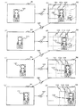
図5には、テンプレートマッチング法による侵入物体の移動量の検出処理を逐次実行して侵入物体を追跡する処理の流れの一例を示してある。
同図では、テンプレート画像91を取得した時刻をt0と表し、所定の時間間隔(例えば、100ms)で逐次入力する入力画像の取得時刻を、入力順に(t0+1)、(t0+2)、・・・と表す。
【0068】
同図(a)には、時刻t0におけるテンプレート画像91を示してある。当該テンプレート画像91中に、時刻t0におけるテンプレート101がある。なお、これらは、それぞれ、上記図3(e)に示したテンプレート画像55、テンプレート65と同一のものである。
【0069】
同図(b)には、時刻(t0+1)における入力画像92を示してある。当該入力画像92において、矩形領域102は時刻t0における侵入物体の位置(テンプレート101の位置)を表しており、矩形領域103はテンプレートマッチングの対象となる領域(探索領域)を表している。
なお、図5(b)では説明を簡単にするため、前述の対象物体の移動量予測に基づいた探索領域の設定方法は用いていないが、移動量予測を用いた場合でも同様に侵入物体の追跡が行える。
【0070】
そして、テンプレートマッチング処理(ステップS11)141を実行すると、テンプレートマッチングの探索領域 103の中でテンプレート101に最も一致する画像104で一致度が最も大きくなり、侵入物体は時刻(t0+1)において画像104の位置に存在していることが分かる。この位置は、時刻t0におけるテンプレート101の位置(x0、y0)から見て相対位置(Δx、Δy)で表される。すなわち、侵入物体は矢印105により示される分だけ移動したことが分かる。
【0071】
そこで、テンプレート更新処理(ステップS13)142により、テンプレート101に最も一致した画像104を時刻(t0+1)における新たなテンプレートとして更新する。すなわち、同図(c)に示されるように、入力画像92から侵入物体の位置104を切り出し、これをテンプレート画像93とし、侵入物体の画像104を時刻(t0+1)における新たなテンプレート111として更新する。
【0072】
この処理をTVカメラ11から逐次入力される入力画像に対して適用する。
具体的には、同図(d)に示されるように、時刻(t0+2)における入力画像94中にテンプレート111の位置112に基づいて探索領域113を設定し、時刻(t0+1)におけるテンプレート画像93中のテンプレート111を用いてテンプレートマッチング処理(ステップS11)143によって侵入物体の位置114を検出する。すると、侵入物体は矢印115で示されるように移動したことが分かる。
【0073】
更に、同図(e)に示されるように、テンプレート更新処理(ステップS13)144によって、時刻(t0+2)におけるテンプレート画像95及び侵入物体のテンプレート121を更新する。
また、同図(f)に示されるように、時刻(t0+3)における入力画像96中にテンプレート121の位置122に基づいて探索領域123を設定し、時刻(t0+2)におけるテンプレート画像95中のテンプレート121を用いてテンプレートマッチング処理(ステップS11)145によって侵入物体の位置124を検出する。すると、侵入物体は矢印125で示されるように移動したことが分かる。
【0074】
更に、同図(g)に示されるように、テンプレート更新処理(ステップS13)146によって、時刻(t0+3)におけるテンプレート画像97及び侵入物体のテンプレート131を更新する。
そして、同図(h)に示されるように、時刻(t0+4)における入力画像98中にテンプレート131の位置132に基づいて探索領域133を設定し、時刻(t0+3)におけるテンプレート画像97中のテンプレート131を用いてテンプレートマッチング処理(ステップS11)147によって侵入物体の位置134を検出する。すると、侵入物体は矢印135で示されるように移動したことが分かる。
このように、テンプレートマッチングを逐次実行することで、侵入物体を追跡することができる。
【0075】
ここで、上記したテンプレートマッチング処理(ステップS11)における探索領域や一致度について具体的に説明する。
上記した探索領域の範囲は、例えば、テンプレートに登録された対象物体の入力画像上での動きによって決定される。
具体例として、撮像装置1として1/3インチCCD(撮像素子サイズ 4.8mm×3.6mm)が用いられ、撮像レンズ12の焦点距離が32mmであり、対象物体までの距離が30mであるといった条件で撮像すると、TVカメラ11の横方向の視野は、30×4.8÷32=4.5mとなる。このTVカメラ11で、移動速度が時速5km/h(約1.39m/s)の対象物体を、画像サイズ 320×240画素、入力間隔0.1s(100ms)で撮像すると、対象物体の入力画像毎の画像上での移動量は、横方向320×1.39×0.1/4.5≒9.88画素となる。
【0076】
また、対象物体がTVカメラ11の方向に向かって移動すると画像上での移動量も大きくなるため、実際の探索領域の範囲は、上記で算出した値の5倍程度の余裕をもって設定する。すなわち、探索領域の横方向の大きさMxを50画素とする。探索領域の縦方向の大きさMyは、TVカメラ11の仰角に依存して、TVカメラ11の取り付け位置によって変化するため、横方向の大きさのおよそ40%程度の値とする。従って、探索範囲は、この例では、テンプレートに対して左右Mx=50画素、上下My=20画素だけ広げた領域とすればよい。
【0077】
また、一致度としては、例えば正規化相関値r(Δx,Δy)を適用することができ、式2のように表される。
【0078】
【数2】
ここで、f(x,y)は入力画像を表している。また、後述する図6を参照して、g(x,y)はテンプレート画像151を表しており、(x0,y0)はテンプレート161の左上の座標を表しており、Dはテンプレート161の大きさを表している。本例では、画像の座標軸としては、画像の左上を原点(0,0)としている。また、上記図3(d)を参照して、Dは二値化画像54で検出された侵入物体の外接矩形64の大きさに相当し、本例では横50画素、縦20画素に相当する。
【0080】
正規化相関値r(Δx,Δy)は、−1≦r(Δx,Δy)≦1の値を取り、入力画像とテンプレートとが全く一致した場合には、“1”となる。
テンプレートマッチングでは、Δx、Δyを探索範囲内で走査させた場合に、すなわち上記した例では−Mx≦Δx≦Mx、−My≦Δy≦Myと変化させた場合に、正規化相関値r(Δx,Δy)が最も大きくなる位置(Δx,Δy)(すなわち、対象物体の移動量)を検出する処理が行われる。
また、前述した対象物体の移動量の予測を行う場合には、Δx、ΔyをΔx’―Mx≦Δx≦Δx’+Mx、Δy’―My≦Δy≦Δy’+Myと変化させる。ここで、Δx’、Δy’は前フレームの対象物体の移動量を表す。
【0081】
次に、上記図2に示した処理手順の続きを説明する。
カメラ雲台制御処理では、上記した侵入物体の移動量の検出処理T2におけるテンプレートマッチング処理(ステップS11)によって検出された侵入物体の位置と、入力画像の中心との変位に応じて、カメラ雲台13の制御を行う(ステップS14)。
【0082】
ここで、図6を参照して、上記したカメラ雲台制御処理(ステップS14)を具体的に説明する。
一例として、テンプレート画像151において、同図に示されるような位置161に侵入物体が検出されたとする。この場合、侵入物体の中心位置をテンプレートの中心162とすると、テンプレート画像151の中心163からのX軸方向の変位dx、Y軸方向の変位dyが算出される。
【0083】
そして、テンプレートの中心位置162が入力画像の中心163と比べて、所定量S以上左側(dx<−S)であればカメラ雲台13を左に回転(パン)させ、所定量S以上右側(dx>S)であればカメラ雲台13を右に回転(パン)させる。また、テンプレートの中心位置162が入力画像の中心163と比べて、所定量S以上上側(dy<−S)であればカメラ雲台13を上に傾け(チルト)させ、所定量S以上下側(dy>S)であれば下に傾け(チルト)させる。
【0084】
このような所定量Sを用いると、侵入物体が画像の中心付近に存在する場合には、カメラ雲台13を制御する必要がなく、このため、所定量Sによってカメラ雲台13の制御を開始する侵入物体の位置を指定することができる。
なお、左、右、上、下のそれぞれについての所定量Sとしては、種々な値が用いられてもよく、例えば、左右上下で同一の値が用いられてもよく、或いは、左右上下でそれぞれ任意な値が用いられてもよい。
【0085】
一例として、左右上下の所定量S=50という値を用いることができる。
また、例えば、所定量Sが小さいほど、侵入物体が少しでも中心から外れたらカメラ雲台13が制御されてしまって画像が見づらくなってしまう可能性はあるが、上記した所定量S=0といった値や、所定量Sとして小さい値を用いることも可能である。
【0086】
また、テンプレート画像151の中心163に対する侵入物体のX軸方向の変位dx、Y軸方向の変位dyの絶対値に応じてパンや、チルトモータの制御速度を変化させるような制御を行うことも可能である。この場合、例えば、X軸方向の変位dx、或いは、Y軸方向の変位dyの絶対値が大きいほど、制御速度を大きくする。
【0087】
また、本例では、侵入物体の追跡として、カメラ雲台13の制御を伴った侵入物体の追跡を行っている。これにより、侵入物体をTVカメラ11の視野内に捉えながら、カメラ雲台13を自動的に制御して、侵入物体を追跡することができる。
【0088】
次に、上記図2に示した処理手順の続きを説明する。
焦点距離情報取得処理では、ワークメモリ27に記録した現在の入力画像を取得した時点の撮像レンズ12の焦点距離fを取得する(ステップS15)。
次に、ズーム倍率算出処理では、テンプレートマッチング処理(ステップS11)で得られた侵入物体の移動量(Δx,Δy)に基づいて、式3によりズーム倍率rfを算出する(ステップS16)。
【0089】
【数3】
上記した式3において、Mx、Myは、テンプレートマッチング法における探索範囲を表している。また、Sx、Syは、安定に追跡することが可能な侵入物体の画像上での最大移動量を表しており、例えば、探索範囲の半分程度、すなわち、上記した例ではSx=25、Sy=10とする。なお、SxやSyの値は、例えば、物体が探索範囲から外れないように探索範囲の半分程度で余裕をもたせるといった程度で、実験などにより設定される。
また、上記した式3では、侵入物体の移動量(Δx,Δy)=(0,0)である場合には、つまり侵入物体の移動量がゼロである場合には、ズーム倍率rf=1.5としている。
【0091】
なお、例えば、ズーム倍率rfが所定の値以上になった場合には、ズーム倍率rfを当該所定の値にして、急激にズームアップしないようにすることも可能である。当該所定の値としては、例えば、1.5を用いることができる。この場合、1回のズームアップで最大50%のズームアップまでが可能となる。
このように、1回のズームアップにおける最大のズーム倍率rf(上限値)を設定すると、例えば、画像の端近くで検出された物体はズームアップによって画像上の視野の外側に飛び出してしまうといった問題を抑制することができる。
【0092】
また、例えば、ズーム倍率rfの上限値(MAX値)を可変とするような構成を用いることも可能である。このような構成では、例えば、画像の画面のサイズと比べてテンプレートが十分に小さい場合には、ズーム倍率rfの上限値を1.5より大きい値とするようなことが可能である。
【0093】
また、例えば、ズームアップに上限を設けるような構成を用いることも可能である。具体的には、一例として、画像の画面の高さがテンプレートの高さの120%以上となる範囲でしかズームアップを行わないようなことや、画像の画面の幅がテンプレートの幅の120%以上となる範囲でしかズームアップを行わないようなことが可能である。これにより、侵入物体の移動量(Δx,Δy)が小さくて多数回のズームアップが為されてテンプレートが画像の画面のサイズを超えてしまうようなことを防ぐことができ、画像を見易くして、安定した動作を確保することができる。
【0094】
また、テンプレートと画像の上端、下端、左端、右端までのそれぞれの距離に基づいてズームアップに上限を設けるような構成にすることも可能である。具体的には、一例として、図7に示すようにテンプレート172と画像171の上端、下端、左端、右端までの距離をそれぞれdu、db、dl、drとし、テンプレート172の上辺、下辺、左辺、右辺がズームアップによって画面の外に超える倍率120/(120−du)、120/(120−db)、160/(160−dl)、160/(160−dr)の中で負の値を除いて最も小さい倍率をズームアップの倍率の上限とする。ここで、画像サイズとして、幅320画素、高さ240画素を想定した。
【0095】
また、対象物体の移動量の予測を行う場合には、前フレームでの対象物体の移動量を(Δx’、Δy’)とした場合、120/{120−(du+Δy’)}、120/{120−(db−Δy’)}、160/{160−(dl+Δx’)}、160/{160−(dr−Δx’)}として、上記と同様にして、テンプレートの上辺、下辺、左辺、右辺がズームアップによって画面の外に超える倍率(ズームアップの倍率の上限)を算出する。
【0096】
なお、例えば、テンプレート172と画像171の上端、下端までの距離du、dbのうちで短い方のみを採用して考慮してズームアップの倍率の上限を算出してもよく、また、テンプレート172と画像171の左端、右端までの距離dl、drのうちで短い方のみを採用して考慮してズームアップの倍率の上限を算出してもよい。
【0097】
次に、撮像レンズ制御処理では、ズーム後の焦点距離f×rfによって、レンズ制御部23を介して撮像レンズ12の焦点距離をf×rfに調整する(ステップS17)。これにより、追跡する対象の侵入物体の画像上での移動速度が所定の値以下に抑えられるように、撮像レンズ12を自動的に調節することができる。当該所定の値としては、上記した例では、横方向が25であり、縦方向が10である。
【0098】
すなわち、追跡する対象の侵入物体の画像上での移動速度が所定の値以上である(又は、所定の値を超える)場合には、撮像レンズ12の焦点距離を小さくし(つまり、ズーム倍率を小さくする、すなわちズームアウトし)、侵入物体の画像上での移動速度を所定の値未満(又は、所定の値以下)にする。また、追跡する対象の侵入物体の画像上での移動速度が所定の値未満である(又は、所定の値以下である)場合には、撮像レンズ12の焦点距離を大きくし(つまり、ズーム倍率を大きくする、すなわちズームアップし)、侵入物体の画像上での移動速度が所定の値になるまで侵入物体をズームアップすることができる。
【0099】
次に、警報・追跡情報表示処理では、例えば、侵入物体を追跡中であることを表す警報を監視員に伝えるため、画像出力部29を介して監視用の画像モニタ5に侵入物体の情報を表示することや、警報出力部30を介して警告灯6を点灯させることなどを行う(ステップS18)。ここで、侵入物体の情報としては、例えば、移動量や、移動経路などの情報を用いることができる。
【0100】
なお、本例では、カメラ雲台13を制御する処理(ステップS14)と、撮像レンズ12を制御する処理(ステップS17)の両方が行われており、上記したカメラ雲台制御に関する所定量Sと、ズーム倍率rfの上限値などとは、例えば、互いに考慮されて実験などにより設定されるのが好ましい。これにより、例えば、カメラ雲台13の制御とズーム倍率rfによるズームアップとが同時に両方為されたような場合に、物体が画像の画面の外に出てしまうようなことを抑制することが可能である。
【0101】
また、本例では、上記図2に示した処理手順を用いたが、他の例として、カメラ雲台制御処理(ステップS14)をズーム倍率算出処理(ステップS16)と撮像レンズ制御処理(ステップS17)との間に設けて実行するような処理手順を用いることも可能である。このような処理手順では、例えば、ズーム倍率算出処理(ステップS16)で算出されたズーム倍率rfを考慮して、ズーム後の侵入物体の位置をズーム倍率rfから予測して、当該予測結果に基づいて、カメラ雲台13の制御処理(ステップS14)を行うようなことが可能である。
【0102】
以上のように、本例の画像監視装置では、撮像装置1によって得られる画像信号に基づいて監視対象領域内の侵入物体を検出し、当該侵入物体の画像信号上での移動方向及び移動量を検出し、当該移動方向及び当該移動量に基づいて当該撮像装置1を搭載する雲台13及び当該撮像装置1の撮像レンズ12を制御しながら当該侵入物体を追跡する物体追跡方法及び物体追跡装置において、当該移動量に基づいて当該撮像装置1の撮像レンズ12を制御する。
【0103】
また、本例の画像監視装置では、上記のような構成において、侵入物体の画像信号上での移動量に基づいて撮像装置1の撮像レンズ12のズーム倍率rfを算出するズーム倍率算出処理(ステップS16)と、当該ズーム倍率算出処理によって算出されたズーム倍率に基づいて当該撮像装置1の撮像レンズ12を制御する撮像レンズ制御処理(ステップS17)を備え、これら少なくとも2種の処理が、侵入物体の移動方向及び移動量を検出するための処理手順に備えられている。
【0104】
また、本例の画像監視装置では、上記のような構成において、ズーム倍率算出処理(ステップS16)では、侵入物体の画像信号上での移動量を所定の値以下に抑えるようにズーム倍率rfを算出する。
【0105】
具体的な一例に係る画像監視装置(以下で、画像監視装置A1と言う)では、少なくとも監視対象とする範囲を撮像する撮像装置1と、当該撮像装置1の視野方向を変えるための当該撮像装置1を搭載する外部信号により制御可能なカメラ雲台13と、当該撮像装置1の画角を変えるための当該撮像装置1に取り付けられた外部信号により制御可能な撮像レンズ12と、当該撮像装置1からの画像信号をデジタルの画像信号に変換する画像入力部(インタフェース)21と、当該画像入力部21からの画像信号を処理する機能を有して例えば少なくともMPU26と画像メモリ25とプログラムメモリ4とワークメモリ27を有する画像処理部と、当該画像処理部からのカメラ雲台13を制御するための制御信号を供給する雲台制御部(インタフェース)22と、当該画像処理部からの撮像レンズ12を制御するための制御信号を供給する撮像レンズ制御部(インタフェース)23を備える。
【0106】
そして、当該画像監視装置(画像監視装置A1)では、画像処理部は、撮像装置1により撮像された画像信号から監視対象領域内の侵入物体を検出し、当該侵入物体の画像信号上での移動方向及び移動量を検出し、当該移動方向に基づいて雲台制御部22を介してカメラ雲台13を制御して撮像装置1の視野方向を調整し、当該移動量に基づいて撮像レンズ12のズーム倍率rfの値を算出し、当該ズーム倍率rfの値に基づいて撮像レンズ制御部23を介して撮像レンズ12を制御して撮像装置1の画角を調整し、これにより、撮像装置1の撮像視野内に侵入した物体を追跡する。
【0107】
また、更に具体的な一例に係る画像監視装置(以下で、画像監視装置A2と言う)では、例えば監視対象とする監視範囲を撮像するTVカメラ11等の画像入力機能1と、当該TVカメラ11等の画像入力機能1が撮像した画像を入力する画像入力部(インタフェース)21と、当該画像入力部21から入力された画像を記憶する画像メモリ25と、物体認識を行う物体追跡装置の動作のプログラムを記憶しているプログラムメモリ4と、当該プログラムメモリ4に保持されているプログラムにしたがって物体追跡装置を動作させる処理装置26と、画像メモリ25に記憶された画像の解析を行うためのワークメモリ27と、音、可視光、振動、回転運動、上下運動等の少なくとも1つ以上で表し人間または補助動物が感知可能な信号を発生する警告表示機能6と、監視用の画像モニタ6を備える。
【0108】
また、当該画像監視装置(画像監視装置A2)では、ワークメモリ27による解析結果に対応して処理装置26の指示によって警告表示機能6に警告を表示させる信号を伝達する警報出力部(インタフェース)30と、ワークメモリ27による解析結果に対応して処理装置26の指示によって監視用の画像モニタ5への画像を送る画像出力部(インタフェース)29と、ワークメモリ27による解析結果に対応して処理装置26の指示によってTVカメラ11等の視野方向を制御するカメラ雲台13と、ワークメモリ27による解析結果に対応して処理装置26の指示によってTVカメラ11等の視野方向を制御させる信号を伝達する雲台制御部(インタフェース)22と、ワークメモリ27による解析結果に対応して処理装置26の指示によってTVカメラ11等の画角を制御する撮像レンズ12と、ワークメモリ27による解析結果に対応して処理装置26の指示によってTVカメラ11等の画角を制御させる信号を伝達する撮像レンズ制御部(インタフェース)23を備える。
【0109】
また、当該画像監視装置(画像監視装置A2)では、プログラムメモリに保持されているプログラムが、画像処理機能1により取得され画像メモリ25に記憶された画像に映る物体を検出する機能と、当該侵入物体の画像信号上での移動方向及び移動量を検出する機能と、当該移動量に基づいて撮像レンズ12のズーム倍率rfの値を算出する機能と、当該移動方向に基づいて雲台制御部22を介してカメラ雲台12を制御して撮像装置1の視野方向を調整する機能と、当該ズーム倍率rfの値に基づいて撮像レンズ制御部23を介して撮像レンズ12を制御して撮像装置1の画角を調整する機能を設け、これにより、TVカメラ11等の撮像視野内に侵入した物体の安定な追跡を実現する。
【0110】
従って、本例の画像監視装置では、撮像装置1を用いた監視装置において、撮像装置1の撮像視野内の侵入物体を当該撮像装置1の画像信号の中から自動的に検出し、当該侵入物体の動きを自動的に検出し、当該侵入物体の動きに応じて当該撮像装置1の撮像方向及び画角を調節することができる。
【0111】
具体的には、本例の画像監視装置では、撮像レンズ12の適切なズーム倍率rfを自動的に調整し、監視領域内に侵入した物体を正確に検出して追跡することができ、これにより、信頼性の高い物体追跡を実現することができる。本例の画像監視装置では、例えば、物体追跡処理によって得られた侵入物体の(表示)画像上での移動量に応じて撮像レンズ12のズーム倍率rf(撮像レンズ12の焦点距離)を自動的に調整することで、侵入物体の(表示)画像上での移動量を所定の値以下に抑えながら(所定の値以上としないように)侵入物体をズームアップして追跡することができる。
【0112】
このように、本例の画像監視装置では、撮像レンズ12の適切な焦点距離を自動的に調整することにより、監視領域内に侵入した物体を適切なズーム倍率rfで正確にかつ安定して検出や追跡することができ、画像監視装置の適用範囲を大きく広げることができる。例えば、対象物体をズームアップして撮像する際などに、対象物体の画像上での移動量が大きくなったような場合においても、安定に追跡動作が実行されるように撮像レンズ12の焦点距離を自動的に調整することができ、信頼性の高い監視システムを簡易に構築することができる。
【0113】
ここで、本例では、画像から物体を検出する方法として差分法を例として用い、また、物体の移動量を検出する方法としてテンプレートマッチング法を例として用いたが、例えば、本例と同様に侵入物体の移動量を検出しながら追跡することが可能な方法であれば、撮像レンズ12のズーム倍率rfを算出して焦点距離を適切に調節することができるため、種々な方法が用いられてもよい。
【0114】
なお、本例の画像監視装置では、撮像装置1の機能により撮像手段が構成されており、処理装置2の機能により画像中物体移動量検出手段が構成されており、処理装置2の機能により撮像レンズ制御手段が構成されており、画像モニタ5の機能により画像表示出力手段が構成されている。
【0115】
次に、本発明に関する比較例を示す。なお、ここで記載する事項は、必ずしも全てが従来技術であるとは限らない。
本比較例に係る画像監視装置の構成としては、概略的には、上記した本発明の実施例に係る上記図1に示される画像監視装置の構成と同様である。
図8には、差分法やテンプレートマッチング法を用いる本比較例に係る画像監視装置により行われる物体追跡処理の手順の一例を示してある。
同図に示した処理手順は、概略的には、例えば、上記した本発明の実施例に係る上記図2に示される処理手順と比べて、テンプレートマッチング法による侵入物体の移動量の検出処理T3においてテンプレート拡大・縮小処理(上記図2のステップS10)が行われず、また、焦点距離情報取得処理(上記図2のステップS15)やズーム倍率算出処理(上記図2のステップS16)や撮像レンズ制御処理(上記図2のステップS17)が行われない点を除いては、上記図2に示される処理手順と同様である。
【0116】
ここで、本発明に係る物体追跡装置や画像監視装置などの構成としては、必ずしも以上に示したものに限られず、種々な構成が用いられてもよい。なお、本発明は、例えば本発明に係る処理を実行する方法或いは方式や、このような方法や方式を実現するためのプログラムなどとして提供することも可能であり、また、例えば物体監視装置や物体検出装置などの種々な装置やシステムとして提供することも可能である。
また、本発明の適用分野としては、必ずしも以上に示したものに限られず、本発明は、種々な分野に適用することが可能なものである。
【0117】
また、本発明に係る物体追跡装置や画像監視装置などにおいて行われる各種の処理としては、例えばプロセッサやメモリ等を備えたハードウエア資源においてプロセッサがROM(Read Only Memory)に格納された制御プログラムを実行することにより制御される構成が用いられてもよく、また、例えば当該処理を実行するための各機能手段が独立したハードウエア回路として構成されてもよい。
また、本発明は上記の制御プログラムを格納したフロッピー(登録商標)ディスクやCD(Compact Disc)−ROMやDVD(Digital Versatile Disk)−ROM等のコンピュータにより読み取り可能な記録媒体や当該プログラム(自体)として把握することもでき、当該制御プログラムを記録媒体からコンピュータに入力してプロセッサに実行させることにより、本発明に係る処理を遂行させることができる。
【0118】
【発明の効果】
以上説明したように、本発明に係る物体追跡装置によると、撮像により得られる画像信号に基づいて画像中の物体を追跡するに際して、画像中における物体の移動量を検出し、当該検出結果に基づいて、撮像を行う撮像レンズを制御するようにしたため、当該撮像レンズを効果的に制御することができる。
【図面の簡単な説明】
【図1】 本発明の一実施例に係る画像監視装置の構成例を示す図である。
【図2】 本発明の一実施例に係る画像監視装置により行われる物体追跡処理の手順の一例を示す図である。
【図3】 差分法を用いて侵入物体を検出する処理の一例の概略と、当該侵入物体の画像をテンプレートに登録する処理の一例の概略を示す図である。
【図4】 テンプレートの拡大・縮小の様子の一例を示す図である。
【図5】 テンプレートマッチング法による侵入物体の移動量の検出処理を逐次実行して侵入物体を追跡する処理の流れの一例を示す図である。
【図6】 検出物体の位置に基づいてカメラ雲台を制御する動作の一例を示す図である。
【図7】 テンプレートと画像の上端、下端、左端、右端までのそれぞれの距離に基づいてズームアップに上限を設ける処理の一例を説明するための図である。
【図8】 画像監視装置により行われる物体追跡処理の手順の一例を示す図である。
【符号の説明】
1・・撮像装置、 2・・処理装置、 3・・操作装置、
4・・外部記憶装置、 5・・画像モニタ、 6・・警告灯、
11・・TVカメラ、 12・・撮像レンズ、 13・・カメラ雲台、
21・・画像入力部、 22・・雲台制御部、 23・・レンズ制御部、
24・・操作入力部、 25・・画像メモリ、 26・・MPU、
27・・ワークメモリ、 28・・外部入出力部、 29・・画像出力部、
30・・警報出力部、 41・・ジョイスティック、 42、43・・ボタン、
51、92、94、96、98・・入力画像、 52・・基準背景画像、
53・・差分画像、 54・・二値化画像、
55、91、93、95、97、151・・テンプレート画像、
61、63・・物体、 62・・変化領域、 64・・外接矩形、
65、81、83、101、111、121、131、161、172・・テンプレート、
71・・減算器、 72・・二値化器、 73・・切り出し器、
82、84、162・・テンプレートの中心位置、
102、112、122、132・・矩形領域、
103、113、123、133・・探索領域、
104、114、124、134・・物体の位置、
105、115、125、135・・矢印、
141、143、145、147・・テンプレートマッチング処理、
142、144、146・・テンプレート更新処理、
163・・画像の中心位置、 171・・画像、[0001]
BACKGROUND OF THE INVENTION
The present invention relates to an object tracking device that tracks an object in an image to be captured, and more particularly to a technique for effectively controlling an imaging lens that performs imaging.
[0002]
[Prior art]
For example, a remote monitoring type monitoring system using an imaging device such as a TV camera (television camera) has been widely used in the past, and many of them are monitored while watching an image displayed on the monitor. It is a so-called manned monitoring system. In a manned monitoring system, it is necessary to monitor in real time an image displayed on the monitor, and to identify intruders such as humans and automobiles entering the monitored area in real time. A heavy burden is placed on the staff.
[0003]
In other words, since the human concentration is limited, in the monitoring system of the manned monitoring system, the occurrence of oversight of the intruding object cannot be ignored, and there is a problem in terms of reliability. In addition, with the explosive spread of surveillance cameras, there are also many scenes where one surveillance person monitors many TV camera images on multiple monitors, and even when multiple TV cameras capture an intruding object at the same time, the intruding object May be missed.
[0004]
Therefore, instead of monitoring by such a person, a camera platform (turning) equipped with a TV camera so that an intruding object is automatically detected by image processing from an image captured by the TV camera and an image of the intruding object is captured. In recent years, a so-called automatic tracking type monitoring system that automatically adjusts the viewing direction and the angle of view by controlling the table to obtain a predetermined notification and alarm processing has been strongly demanded. ing.
[0005]
By the way, in order to realize such a system, it is necessary to use a predetermined monitoring method, detect an object to be monitored that should be regarded as an intruding object from an image signal, and detect a movement of the intruding object.
One example of a monitoring method for detecting such an intruding object is a method called a difference method, which has been widely used. The difference method is a method in which an input image obtained by a TV camera is compared with a reference background image created in advance, that is, an image in which an object to be detected is not captured, a difference in luminance value is obtained for each pixel, and the difference value is obtained. Is detected as an object. In addition, an application example of the difference method has been studied (for example, see Patent Document 1).
[0006]
Furthermore, there is a method called a template matching method as an example of a monitoring method for detecting the amount of movement of an intruding object, which has been widely used conventionally as in the difference method. In the template matching method, an image of an intruding object detected by a difference method or the like is registered as a template, and a position most similar to the template image is detected among images sequentially input (see, for example, Non-Patent Document 1). .) Normally, when tracking a target object using template matching, in order to follow a change in the posture of the target object, an image of the position of the target object detected by the matching process is sequentially updated as a template.
[0007]
[Patent Document 1]
JP-A-9-73541
[Non-Patent Document 1]
Supervised by Hideyuki Tamura, “Introduction to Computer Image Processing”, Soken Publishing, 1985, p. 149-153
[0008]
[Problems to be solved by the invention]
By the way, when monitoring the target object, it is required to zoom in on the intruding object as much as possible. However, if the target object is zoomed up (that is, the focal length of the imaging lens is increased) and monitored, the amount of movement of the target object in the displayed image increases, so that the target image is input from within the region of the sequentially input image. There arises a problem that the object comes off and the tracking of the intruding object cannot be performed stably. Therefore, as an example, setting the focal length of the imaging lens so as to zoom in on the intruding object as much as possible without degrading the tracking performance of the intruding object is important in providing a reliable object tracking device. become.
[0009]
As described above, in an automatic tracking type monitoring system, it is important to zoom in on a target object to be monitored without degrading the reliability of the object tracking function as much as possible. Since the focal length varies depending on the size of the image sensor, it requires skill to set it. Furthermore, if the distance between the TV camera and the target object changes, the zoom magnification must be changed accordingly. There is a problem.
[0010]
The present invention has been made in view of such conventional circumstances, and provides an object tracking device that can effectively control an imaging lens that performs imaging when tracking an object in an image to be captured. For the purpose.
[0011]
[Means for Solving the Problems]
In order to achieve the above object, the object tracking device according to the present invention performs the following processing when tracking an object in an image based on an image signal obtained by an imaging means.
That is, the object movement amount detection means in the image detects the movement amount of the object in the image, and the imaging lens control means detects the imaging lens of the imaging means based on the detection result by the object movement amount detection means in the image. Control.
Therefore, the imaging lens of the imaging means can be effectively controlled by controlling the imaging lens of the imaging means based on the amount of movement of the object in the image.
[0012]
In this specification, the term “tracking” is used for explanation, but for example, the term “tracking” is also a similar term and is included in the present invention.
In this specification, the term “image” is used for explanation. For example, the term “video” is a similar term and is included in the present invention. In addition, for example, an image referred to in the present specification refers to a moving image when it is temporally continuous. For example, as to a still image, an image of one frame in the moving image, Some of the images and still images that are unrelated to moving images.
[0013]
Here, various imaging means may be used, and for example, a camera or the like can be used.
Various image signals may be used.
Various objects may be used as the object.
Further, the object in the image corresponds to, for example, the image portion of the target object existing in the image.
[0014]
Various modes may be used as a mode for tracking an object in an image. For example, when a target object moves, such a mode that the object is included in the image is used. Can do.
Further, as the object movement amount detection means in the image, for example, a means that uses processing by template matching based on the detection result of the object in the image can be used.
[0015]
Further, as the amount of movement of the object in the image detected by the object movement amount detection means in the image, for example, the amount of movement of the object in the image is used instead of the amount of movement of the object in the real world. For example, even if the amount of movement of the object in the real world is the same, the amount of movement of the object in the image may differ depending on how the image is taken. On the other hand, for example, even if the amount of movement of the object in the real world is different, the amount of movement of the object in the image can be the same depending on how the image is taken.
[0016]
Various lenses may be used as the imaging lens of the imaging means, and for example, a zoom lens can be used.
Various modes may be used as a mode for controlling the imaging lens of the imaging unit based on the detection result by the object movement amount detection unit in the image.
[0017]
In the object tracking device according to the present invention, as one configuration example, the imaging lens control unit calculates the zoom magnification of the imaging lens of the imaging unit based on the detection result by the object movement amount detection unit in the image, and based on the calculation result. To control the imaging lens of the imaging means.
Therefore, the imaging lens of the imaging unit can be effectively controlled by controlling the imaging lens of the imaging unit based on the zoom magnification calculated based on the amount of movement of the object in the image.
[0018]
Here, various zoom magnifications may be used. For example, a value that specifies the size of an actual area displayed in one frame of an image is used.
Various methods may be used as the method of calculating the zoom magnification of the imaging lens of the imaging unit based on the detection result by the object movement amount detection unit in the image.
Various methods may be used as a method of controlling the imaging lens of the imaging unit based on the calculation result of the zoom magnification. For example, the imaging lens of the imaging unit is used so as to realize the calculated zoom magnification. A way of moving can be used.
[0019]
In the object tracking device according to the present invention, as one configuration example, the imaging lens control unit has a predetermined amount (hereinafter referred to as a predetermined value) based on a detection result by the object movement amount detection unit in the image. The zoom magnification of the imaging lens of the imaging means is calculated so as to be less than or less than the value P).
Therefore, the imaging lens of the imaging unit can be effectively controlled by calculating the zoom magnification of the imaging lens of the imaging unit so that the amount of movement of the object in the image is less than or less than a predetermined value.
[0020]
Here, as an aspect in which the amount of movement of the object in the image is less than or less than a predetermined value, for example, an aspect in which the amount of movement of the object in the image is less than or equal to a predetermined value is used. Alternatively, an aspect in which the amount of movement of the object in the image is less than a predetermined value may be used.
[0021]
The amount of movement of the object in the image corresponds to, for example, the amount of movement of the object in the frame of the image. For example, the amount of movement of the object can be detected based on the number of pixels constituting the frame.
Various values may be used as the predetermined value (predetermined value P) relating to the amount of movement of the object in the image. For example, to prevent the moving speed of the object in the frame from being too fast. It can be set in consideration.
[0022]
In the object tracking apparatus according to the present invention, as one configuration example, the image display output unit displays and outputs an image using an image signal obtained by the imaging unit. Further, as an example of the configuration, the imaging lens control unit is configured such that the amount of movement of the object in the image displayed and output by the image display output unit is based on a detection result by the object movement amount detection unit in the image. The zoom magnification of the imaging lens of the imaging means is calculated so as to be less than or less than a predetermined value Q).
[0023]
Therefore, the image pickup lens of the image pickup means is effectively controlled by calculating the zoom magnification of the image pickup lens of the image pickup means so that the amount of movement of the object in the displayed and output image is less than or less than a predetermined value. For example, an image that is displayed and output can be easily viewed by a person who sees it.
[0024]
Here, as an aspect in which the amount of movement of the object in the displayed and output image is equal to or less than a predetermined value, for example, the amount of movement of the object in the displayed and output image is equal to or less than the predetermined value. An aspect may be used, or an aspect may be used in which the amount of movement of an object in an image to be displayed and output is less than a predetermined value.
[0025]
Also, calculating the zoom magnification of the imaging lens of the imaging means so that the amount of movement of the object in the displayed and output image is less than or less than a predetermined value is not necessarily performed while the image is displayed and output. Good. For example, the image pickup lens of the image pickup means is configured so that the amount of movement of the object in the image that is displayed and output is assumed to be less than or less than a predetermined value, assuming that no image is actually displayed and output, It is also possible to use a configuration that calculates the zoom magnification of the image, and in this configuration, the image display output means is not necessarily provided.
[0026]
Various image display output means may be used. For example, a display device that displays and outputs an image corresponding to the image signal on the screen can be used. When such a display device is used, the movement amount of the object in the displayed and output image corresponds to, for example, the movement amount of the object on the screen.
Various values may be used as the predetermined value (predetermined value Q) relating to the amount of movement of the object in the displayed and output image. For example, the moving speed of the object in terms of the visibility of the image It can be set taking into consideration that it is not too fast.
[0027]
Below, the structural example which concerns on this invention is shown further.
The object tracking apparatus according to the present invention includes, as one configuration example, an in-image object detecting unit that detects an object in the image, and as one configuration example, detects the object moving direction detection in the image that detects the moving direction of the object in the image. And an imaging direction control means for controlling the imaging direction by the imaging means based on the detection result by the object moving direction detection means in the image.
[0028]
Here, as the object detection means in the image, for example, a means using processing by a difference method can be used.
Further, as the object moving direction detection means in the image, for example, a means that uses processing by template matching based on the detection result of the object in the image can be used.
Various imaging direction control means may be used. For example, a pan head for controlling the orientation of the imaging means may be used.
[0029]
In the object tracking device according to the present invention, as an example of the configuration, it is possible to use an aspect in which an upper limit value and a lower limit value are provided for the zoom magnification. For example, an object is present in a predetermined ratio area in one frame of an image. For example, a mode in which an upper limit value of the zoom magnification at the time of zooming up is provided can be used.
[0030]
In the object tracking apparatus according to the present invention, as one configuration example, when performing processing by template matching, it is possible to use a mode in which the size of the template is adjusted according to a change in zoom magnification.
In the object tracking device according to the present invention, as an example, it is possible to use a mode in which a predetermined relationship is set between the mode of controlling the imaging lens and the mode of controlling the imaging direction.
[0031]
Hereinafter, configuration examples (1) to (4) according to the present invention will be further described.
(1) In an object tracking device that tracks an object in an image based on an image signal obtained by an imaging means,
An object position detection means for detecting the position of the object in the image;
An object movement amount detection means for detecting an object movement amount in the image;
An imaging lens control means for controlling the imaging lens of the imaging means based on the detection result by the object movement amount detection means in the image;
An object tracking device comprising:
[0032]
(2) In the object tracking device according to (1) above,
The imaging lens control means calculates the zoom magnification of the imaging lens of the imaging means based on the detection result by the object position detection means in the image and the detection result by the object movement amount detection means in the image, and based on the calculation result, Control the imaging lens,
An object tracking device.
[0033]
(3) In the object tracking device according to (2) above,
The imaging lens control unit makes the distance between the object position and the upper end, lower end, left end, and right end of the image based on the detection result by the object position detection unit in the image greater than or equal to a predetermined value, and Calculating the zoom magnification of the imaging lens of the imaging means so that the amount of movement of the object in the image is less than or less than a predetermined value based on the detection result by the object movement amount detection means;
An object tracking device.
[0034]
(4) In the object tracking device according to (3) above,
The imaging lens control means determines that the distance between the object position and the upper end, lower end, left end, and right end of the image is a predetermined value or more based on the detection result by the object position detection means in the image and the detection result by the object movement amount detection means in the image. Alternatively, the zoom magnification of the imaging lens of the imaging unit is calculated so that the amount of movement of the object in the image is less than or less than a predetermined value based on the detection result by the object movement amount detection unit in the image. To
An object tracking device.
[0035]
DETAILED DESCRIPTION OF THE INVENTION
An embodiment according to the present invention will be described with reference to the drawings.
FIG. 1 shows a hardware configuration example of an image monitoring apparatus to which an object tracking apparatus according to the present invention is applied.
The image monitoring device of this example includes an
[0036]
The
The
[0037]
The operating device 3 includes a joystick 41, a
Note that the
[0038]
Specifically, the output of the
[0039]
The
The
[0040]
Here, the
[0041]
The
[0042]
The
[0043]
An example of the procedure of the object tracking process using the difference method and the template matching method performed by the image monitoring apparatus of this example will be shown.
FIG. 2 shows an example of the procedure of such processing.
First, in the initialization process, the external device, the variable, the
[0044]
Next, an intruding object detection process T1 (step S2 to step S6) is performed by a difference method.
That is, in the first image input process, an input image having a horizontal size of 320 pixels and a height of 240 pixels is obtained from the TV camera 11 (step S2).
In the difference processing, a difference in luminance value for each pixel is calculated between the input image obtained in the first image input processing and a reference background image that is created in advance and does not show an intruding object (step S3). .
[0045]
In the binarization process, the pixel value of the pixel whose pixel value (difference value) of the difference image obtained by the difference process is less than the predetermined threshold Th is set to “0”, and the pixel of the pixel that is equal to or greater than the predetermined threshold Th A binarized image is obtained with a value of “255” (step S4). Here, for example, Th = 20 is used as the predetermined threshold Th. Further, the pixel value of one pixel is calculated by 8 bits (“0” to “255”).
[0046]
In the labeling process, a block of pixels having the pixel value “255” in the binarized image obtained by the binarization process is detected so that each can be distinguished by being numbered (step S5).
In the intruding object presence determination process, it is determined that there is an intruding object in the monitoring target area when a group of pixels having the pixel value “255” numbered in the labeling process satisfies a predetermined condition (step S6). . Here, as the predetermined condition, for example, a condition that the width is 20 pixels or more and the height is 50 pixels or more is used.
[0047]
When the intruding object presence determination process determines that an intruding object exists, the process proceeds to the alarm / detection information display process (step S7). When it is determined that no intruding object exists, the above-described process is performed again. The process proceeds to the first image input process (step S2), and the process by the difference method is executed again.
[0048]
Here, with reference to FIG. 3, the above-described intruding object detection processing will be specifically described.
In the figure, an outline of an example of a process for detecting an intruding object using the above-described difference method and an outline of an example of a process for registering an image of the intruding object described later in a template are shown.
FIG. 4A shows the
[0049]
FIG. 3C shows a
FIG. 4D shows a
[0050]
Then, the
[0051]
Next, the continuation of the processing procedure shown in FIG. 2 will be described.
In the alarm / detection information display processing, for example, in order to transmit a warning indicating that an intruding object has been found to the monitoring staff, information on the intruding object is displayed on the monitoring image monitor 5 via the image output unit 29. Then, the warning
[0052]
Next, detection processing T2 (steps S8 to S13) of the amount of movement of the intruding object by the template matching method is performed.
That is, in the template registration process, an image of an intruding object in the input image is cut out based on the circumscribed rectangle of the pixel block having the pixel value “255” numbered in the labeling process (step S5) as a template. Register (step S8).
[0053]
In the second image input process, as in the first image input process (step S2) described above, an input image having a horizontal size of 320 pixels and a height of 240 pixels is obtained from the TV camera 11 (step S9). At that time, the focal length of the imaging lens 12 of the
In the template enlargement / reduction processing, the focal length f ′ recorded in the
[0054]
In the template matching process, an image having the highest degree of coincidence with the template is detected from the input images obtained in the second image input process. Usually, since it takes a long time to compare the template and the entire input image, an image having the highest degree of coincidence with the template in the search area is detected with a predetermined range as a search area for the template (step S11).
[0055]
Note that the result of the template matching process for the previous frame is recorded, and the search area is set based on the result, so that the search area can be narrowed and the amount of calculation can be reduced. In other words, intruders and vehicles subject to tracking rarely change their direction of movement suddenly, and when the amount of movement of the target object is determined in the template matching process of the previous frame, the amount of movement is the same in the next frame. Expected to be. Therefore, using a template position (x0, y0) and a movement amount (Δx, Δy) of a target object (described later) detected by the template matching process of the previous frame, a predetermined range centered on (x0 + Δx, y0 + Δy) is set as a search region. By doing so (movement amount prediction), template matching processing in which the motion of the target object is predicted can be performed.
[0056]
In the coincidence degree determination process, a coincidence degree r (Δx, Δy), which will be described later, is determined, and when the normalized correlation value represented by
[0057]
Here, the high degree of coincidence means that there is an image similar to the template in the input image, that is, there is an intruding object in the monitoring target area, and its position is viewed from the template position (x0, y0) described later. This means that the position is relatively (Δx, Δy). In this case, the amount of movement of the intruding object is subsequently detected. In addition, the low degree of coincidence means that there is no image similar to the template in the input image, that is, there is no intruding object in the monitoring target area. In this case, the first image input processing is performed. Then, the intruding object is detected again by the difference method.
[0058]
In the template update process, the input image obtained in the second image input process (step S9) described above is cut out based on the newly obtained position of the intruding object and is used as a new template image (step S13). In this way, by updating the template sequentially, the latest image of the intruding object is recorded in the template, and the amount of movement of the intruding object can be detected stably even when the intruding object changes its posture. .
[0059]
Here, the template enlargement / reduction processing (step S10) will be described in detail with reference to FIG. In the example shown in the figure, the case where the template is enlarged is shown, but the same applies to the case where the template is reduced.
FIG. 4A shows an example of an
The zoom magnification r of the template is expressed as
[0060]
[Expression 1]
For example, assuming that the focal length f ′ of the imaging lens 12 of the
[0062]
In the example shown in the figure, in the XY orthogonal coordinate system, the length Tx in the X-axis direction of the
[0063]
Further, immediately after the intruding object is detected in the intruding object detection process T1, the template update process (step S13) is not executed. Therefore, the focal length f of the imaging lens 12 of the
[0064]
When the template enlargement / reduction process (step S10) is performed as in this example, the template update process (step S13) uses the focal length f ′ recorded in the
[0065]
Here, with reference to FIG. 3 and FIG. 5, the above-described detection processing of the amount of movement of the intruding object will be described in detail.
FIG. 3 shows the
[0066]
Then, the intruding object shown in the
[0067]
FIG. 5 shows an example of a flow of processing for tracking the intruding object by sequentially executing the detection processing of the moving amount of the intruding object by the template matching method.
In the figure, the time when the
[0068]
FIG. 4A shows a
[0069]
FIG. 4B shows an
In FIG. 5B, for the sake of simplicity, the search area setting method based on the above-described target object movement amount prediction is not used. However, even when the movement amount prediction is used, the intruding object is similarly detected. Can be tracked.
[0070]
Then, when the template matching process (step S11) 141 is executed, the degree of coincidence becomes the largest in the
[0071]
Therefore, the template 104 (step S13) 142 updates the
[0072]
This process is applied to input images sequentially input from the
Specifically, as shown in FIG. 4D, the
[0073]
Further, as shown in FIG. 8E, the template update process (step S13) 144 updates the
Also, as shown in FIG. 5F, a
[0074]
Further, as shown in FIG. 6G, the template update process (step S13) 146 updates the
Then, as shown in FIG. 9H, a
In this way, an intruding object can be tracked by sequentially executing template matching.
[0075]
Here, the search area and the degree of matching in the template matching process (step S11) will be specifically described.
The range of the search area described above is determined by, for example, the movement of the target object registered in the template on the input image.
As a specific example, a 1/3 inch CCD (imaging element size: 4.8 mm × 3.6 mm) is used as the
[0076]
Further, since the amount of movement on the image increases as the target object moves in the direction of the
[0077]
As the degree of coincidence, for example, a normalized correlation value r (Δx, Δy) can be applied, and is expressed as
[0078]
[Expression 2]
Here, f (x, y) represents an input image. Referring to FIG. 6 described later, g (x, y) represents the
[0080]
The normalized correlation value r (Δx, Δy) takes a value of −1 ≦ r (Δx, Δy) ≦ 1, and is “1” when the input image and the template completely match.
In template matching, when Δx and Δy are scanned within the search range, that is, in the above example, when −Mx ≦ Δx ≦ Mx and −My ≦ Δy ≦ My, the normalized correlation value r (Δx , Δy) is detected to detect the position (Δx, Δy) (that is, the amount of movement of the target object).
Further, when the above-described movement amount of the target object is predicted, Δx and Δy are changed to Δx′−Mx ≦ Δx ≦ Δx ′ + Mx and Δy′−My ≦ Δy ≦ Δy ′ + My. Here, Δx ′ and Δy ′ represent the amount of movement of the target object in the previous frame.
[0081]
Next, the continuation of the processing procedure shown in FIG. 2 will be described.
In the camera head control process, the camera head is determined according to the displacement between the position of the intruding object detected by the template matching process (step S11) and the center of the input image in the moving object detection process T2 described above. 13 is controlled (step S14).
[0082]
Here, with reference to FIG. 6, the camera pan head control process (step S14) will be described in detail.
As an example, it is assumed that an intruding object is detected at a
[0083]
Then, if the
[0084]
When such a predetermined amount S is used, there is no need to control the
Note that various values may be used as the predetermined amount S for each of left, right, upper, and lower. For example, the same value may be used in the left, right, up, and down directions, or in the left, right, up, and down directions, respectively. Any value may be used.
[0085]
As an example, a value of a predetermined amount S = 50 on the left, right, top and bottom can be used.
Further, for example, as the predetermined amount S is smaller, there is a possibility that the
[0086]
It is also possible to perform control such as changing the control speed of the pan and tilt motors according to the absolute values of the displacement dx in the X-axis direction and the displacement dy in the Y-axis direction with respect to the
[0087]
In this example, as the tracking of the intruding object, the tracking of the intruding object with the control of the
[0088]
Next, the continuation of the processing procedure shown in FIG. 2 will be described.
In the focal length information acquisition process, the focal length f of the imaging lens 12 at the time when the current input image recorded in the
Next, in the zoom magnification calculation process, the zoom magnification rf is calculated by Equation 3 based on the movement amount (Δx, Δy) of the intruding object obtained in the template matching process (step S11) (step S16).
[0089]
[Equation 3]
In Equation 3 above, Mx and My represent search ranges in the template matching method. Sx and Sy represent the maximum movement amount on the image of the intruding object that can be stably tracked. For example, about half of the search range, that is, in the above example, Sx = 25, Sy = 10 is assumed. Note that the values of Sx and Sy are set by experiment or the like, for example, so that an object has a margin at about half of the search range so that the object does not fall out of the search range.
In the above equation 3, when the moving amount of the intruding object (Δx, Δy) = (0, 0), that is, when the moving amount of the intruding object is zero, the zoom magnification rf = 1. Five.
[0091]
For example, when the zoom magnification rf is equal to or greater than a predetermined value, the zoom magnification rf can be set to the predetermined value so that the zoom-up is not suddenly increased. As the predetermined value, for example, 1.5 can be used. In this case, it is possible to zoom up to a maximum of 50% with one zoom-up.
In this way, when the maximum zoom magnification rf (upper limit value) in one zoom-up is set, for example, an object detected near the edge of the image jumps out of the field of view on the image due to the zoom-up. Can be suppressed.
[0092]
Further, for example, a configuration in which the upper limit value (MAX value) of the zoom magnification rf is variable can be used. In such a configuration, for example, when the template is sufficiently smaller than the screen size of the image, the upper limit value of the zoom magnification rf can be set to a value larger than 1.5.
[0093]
In addition, for example, a configuration in which an upper limit is set for zooming up can be used. Specifically, as an example, zooming is performed only in a range where the image screen height is 120% or more of the template height, or the image screen width is 120% of the template width. It is possible to zoom in only within the above range. As a result, it is possible to prevent the amount of movement (Δx, Δy) of the intruding object from being small and zooming in many times, so that the template does not exceed the screen size of the image. , Can ensure stable operation.
[0094]
It is also possible to employ a configuration in which an upper limit is provided for zooming up based on the distance between the template and the upper end, lower end, left end, and right end of the image. Specifically, as an example, as shown in FIG. 7, the distances between the
[0095]
In addition, when the amount of movement of the target object is predicted, if the amount of movement of the target object in the previous frame is (Δx ′, Δy ′), 120 / {120− (du + Δy ′)}, 120 / { 120− (db−Δy ′)}, 160 / {160− (dl + Δx ′)}, 160 / {160− (dr−Δx ′)}, and the upper side, the lower side, the left side, and the right side of the template in the same manner as described above. Magnification that exceeds the outside of the screen by zooming up (upper limit of zooming magnification) is calculated.
[0096]
Note that, for example, the upper limit of the zoom-up magnification may be calculated by considering only the shorter one of the distances du and db between the
[0097]
Next, in the imaging lens control process, the focal length of the imaging lens 12 is adjusted to f × rf via the
[0098]
That is, when the moving speed on the image of the intruding object to be tracked is equal to or higher than a predetermined value (or exceeds a predetermined value), the focal length of the imaging lens 12 is reduced (that is, the zoom magnification is increased). The moving speed of the intruding object on the image is set to be less than a predetermined value (or less than a predetermined value). Further, when the moving speed on the image of the intruding object to be tracked is less than a predetermined value (or less than the predetermined value), the focal length of the imaging lens 12 is increased (that is, the zoom magnification). Can be zoomed up until the moving speed of the intruding object on the image reaches a predetermined value.
[0099]
Next, in the alarm / tracking information display processing, for example, in order to transmit an alarm indicating that the intruding object is being tracked to the monitor, the intruding object information is sent to the monitoring image monitor 5 via the image output unit 29. Displaying or lighting the
[0100]
In this example, both the process for controlling the camera head 13 (step S14) and the process for controlling the imaging lens 12 (step S17) are performed. The upper limit value of the zoom magnification rf and the like are preferably set by experiment, taking into consideration each other. As a result, for example, when the control of the
[0101]
In this example, the processing procedure shown in FIG. 2 is used. As another example, the camera head control process (step S14), the zoom magnification calculation process (step S16), and the imaging lens control process (step S17) are performed. It is also possible to use a processing procedure that is provided between and executed. In such a processing procedure, for example, the position of the invading object after zooming is predicted from the zoom magnification rf in consideration of the zoom magnification rf calculated in the zoom magnification calculation processing (step S16), and based on the prediction result. Thus, it is possible to perform control processing of the camera pan head 13 (step S14).
[0102]
As described above, in the image monitoring apparatus of this example, an intruding object in the monitoring target area is detected based on the image signal obtained by the
[0103]
Further, in the image monitoring apparatus of the present example, in the configuration as described above, zoom magnification calculation processing (step for calculating the zoom magnification rf of the imaging lens 12 of the
[0104]
Further, in the image monitoring apparatus of the present example, in the configuration as described above, in the zoom magnification calculation process (step S16), the zoom magnification rf is set so that the amount of movement of the intruding object on the image signal is suppressed to a predetermined value or less. calculate.
[0105]
In an image monitoring apparatus according to a specific example (hereinafter referred to as image monitoring apparatus A1), an
[0106]
In the image monitoring apparatus (image monitoring apparatus A1), the image processing unit detects an intruding object in the monitoring target area from the image signal captured by the
[0107]
Further, in an image monitoring apparatus according to a more specific example (hereinafter referred to as an image monitoring apparatus A2), for example, an
[0108]
In the image monitoring device (image monitoring device A2), an alarm output unit (interface) 30 that transmits a signal for displaying a warning on the
[0109]
In the image monitoring apparatus (image monitoring apparatus A2), the program stored in the program memory detects the object appearing in the image acquired by the
[0110]
Therefore, in the image monitoring apparatus of this example, in the monitoring apparatus using the
[0111]
Specifically, in the image monitoring apparatus of the present example, an appropriate zoom magnification rf of the imaging lens 12 can be automatically adjusted to accurately detect and track an object that has entered the monitoring area. Reliable object tracking can be realized. In the image monitoring apparatus of this example, for example, the zoom magnification rf (focal length of the imaging lens 12) of the imaging lens 12 is automatically set in accordance with the amount of movement of the intruding object on the (display) image obtained by the object tracking process. By adjusting to, the intruding object can be zoomed up and tracked while keeping the moving amount of the intruding object on the (display) image below a predetermined value (so as not to exceed the predetermined value).
[0112]
As described above, in the image monitoring apparatus of the present example, by automatically adjusting an appropriate focal length of the imaging lens 12, an object that has entered the monitoring area is accurately and stably detected with an appropriate zoom magnification rf. Can be traced, and the application range of the image monitoring apparatus can be greatly expanded. For example, when the target object is zoomed in and imaged, the focal length of the imaging lens 12 is such that the tracking operation can be performed stably even when the amount of movement of the target object on the image increases. Can be automatically adjusted, and a highly reliable monitoring system can be easily constructed.
[0113]
In this example, the difference method is used as an example of a method for detecting an object from an image, and the template matching method is used as an example of a method for detecting the amount of movement of an object. Any method that can be tracked while detecting the amount of movement of the intruding object can calculate the zoom magnification rf of the imaging lens 12 and appropriately adjust the focal length. Therefore, various methods are used. Also good.
[0114]
In the image monitoring apparatus of this example, an imaging unit is configured by the function of the
[0115]
Next, comparative examples relating to the present invention will be shown. Note that the matters described here are not necessarily all related to the prior art.
The configuration of the image monitoring apparatus according to this comparative example is generally the same as the configuration of the image monitoring apparatus shown in FIG. 1 according to the above-described embodiment of the present invention.
FIG. 8 shows an example of the procedure of the object tracking process performed by the image monitoring apparatus according to this comparative example using the difference method or the template matching method.
The processing procedure shown in the figure is roughly compared with the processing procedure shown in FIG. 2 according to the embodiment of the present invention described above, for example, the detection processing T3 of the moving amount of the intruding object by the template matching method. Template enlargement / reduction processing (step S10 in FIG. 2) is not performed, and focal length information acquisition processing (step S15 in FIG. 2), zoom magnification calculation processing (step S16 in FIG. 2), and imaging lens control are performed. The processing procedure is the same as that shown in FIG. 2 except that the processing (step S17 in FIG. 2) is not performed.
[0116]
Here, the configurations of the object tracking device and the image monitoring device according to the present invention are not necessarily limited to those described above, and various configurations may be used. The present invention can also be provided as a method or method for executing the processing according to the present invention, a program for realizing such a method or method, and the like, for example, an object monitoring device or an object. It can also be provided as various devices and systems such as a detection device.
The application field of the present invention is not necessarily limited to the above-described fields, and the present invention can be applied to various fields.
[0117]
In addition, as various processes performed in the object tracking device and the image monitoring device according to the present invention, for example, a control program stored in a ROM (Read Only Memory) in a hardware resource including a processor, a memory, etc. A configuration controlled by execution may be used, and for example, each functional unit for executing the processing may be configured as an independent hardware circuit.
The present invention also provides a computer-readable recording medium such as a floppy (registered trademark) disk, a CD (Compact Disc) -ROM, and a DVD (Digital Versatile Disk) -ROM storing the above control program, and the program itself. The processing according to the present invention can be performed by inputting the control program from a recording medium to a computer and causing the processor to execute the control program.
[0118]
【The invention's effect】
As described above, according to the object tracking device of the present invention, when tracking an object in an image based on an image signal obtained by imaging, the amount of movement of the object in the image is detected, and based on the detection result. Thus, since the imaging lens that performs imaging is controlled, the imaging lens can be effectively controlled.
[Brief description of the drawings]
FIG. 1 is a diagram illustrating a configuration example of an image monitoring apparatus according to an embodiment of the present invention.
FIG. 2 is a diagram illustrating an example of a procedure of object tracking processing performed by an image monitoring apparatus according to an embodiment of the present invention.
FIG. 3 is a diagram illustrating an outline of an example of processing for detecting an intruding object using a difference method and an example of processing for registering an image of the intruding object in a template.
FIG. 4 is a diagram illustrating an example of how a template is enlarged or reduced.
FIG. 5 is a diagram illustrating an example of a flow of processing for tracking an intruding object by sequentially executing detection processing of the amount of movement of the intruding object by a template matching method.
FIG. 6 is a diagram illustrating an example of an operation for controlling a camera platform based on the position of a detected object.
FIG. 7 is a diagram for explaining an example of a process for setting an upper limit for zooming in based on the distance between the template and the upper end, lower end, left end, and right end of the image.
FIG. 8 is a diagram illustrating an example of a procedure of object tracking processing performed by the image monitoring apparatus.
[Explanation of symbols]
1 .... Imaging device, 2 .... Processing device, 3 .... Operating device,
4 .... External storage device, 5 .... Image monitor, 6 .... Warning light,
11 .... TV camera, 12 .... Imaging lens, 13 .... Camera head,
21 ..
24..Operation input section 25.Image memory 26.MPU
27..Work memory 28.External input / output unit 29.Image output unit
30..Alarm output part, 41..joystick, 42, 43 ... button,
51, 92, 94, 96, 98 ...
53 ... Differential image, 54 ... Binary image,
55, 91, 93, 95, 97, 151 .. template image,
61, 63 ... Object, 62 ... Change area, 64 ... circumscribed rectangle,
65, 81, 83, 101, 111, 121, 131, 161, 172 .. template,
71 .. Subtractor, 72 .. Binarizer, 73.
82, 84, 162 .. center position of template,
102, 112, 122, 132 .. rectangular area,
103, 113, 123, 133 .. search area,
104, 114, 124, 134 .. position of the object,
105, 115, 125, 135 ... Arrows
141, 143, 145, 147 .. template matching processing,
142, 144, 146 .. template update processing,
163 .. center position of
Claims (2)
画像中における物体の位置を検出する画像中物体位置検出手段と、
画像中における物体の移動量を検出する画像中物体移動量検出手段と、
画像の上端、下端、左端、右端のうちの1つ以上の端について画像中物体位置検出手段による検出結果に基づいて物体の位置とその端との距離が所定の値以上又はより大きくなるようにし、且つ、画像中物体移動量検出手段による検出結果に基づき画像中における物体の移動量が所定の値以下又は未満となるように、撮像手段の撮像レンズを制御する撮像レンズ制御手段と、
を備えたことを特徴とする物体追跡装置。In an object tracking device that tracks an object in an image based on an image signal obtained by an imaging means,
An object position detection means for detecting the position of the object in the image;
An object movement amount detection means for detecting an object movement amount in the image;
Based on the detection result by the object position detection means in the image for one or more of the upper end, the lower end, the left end, and the right end of the image, the distance between the position of the object and the end is set to be a predetermined value or larger. And an imaging lens control means for controlling the imaging lens of the imaging means so that the movement amount of the object in the image is less than or less than a predetermined value based on the detection result by the object movement amount detection means in the image ;
An object tracking device comprising:
画像中における物体の位置を検出する画像中物体位置検出手段と、 An object position detection means for detecting the position of the object in the image;
画像中における物体の移動量を検出する画像中物体移動量検出手段と、 An object movement amount detection means for detecting an object movement amount in the image;
画像の上端、下端、左端、右端のうちの1つ以上の端について画像中物体位置検出手段による検出結果及び画像中物体移動量検出手段による検出結果の両方に基づいて物体の位置とその端との距離が所定の値以上又はより大きくなるようにし、且つ、画像中物体移動量検出手段による検出結果に基づき画像中における物体の移動量が所定の値以下又は未満となるように、撮像手段の撮像レンズを制御する撮像レンズ制御手段と、 The position of the object and its end based on both the detection result by the object position detection means in the image and the detection result by the object movement amount detection means in the image for one or more of the upper end, the lower end, the left end, and the right end of the image Of the imaging unit so that the distance of the object in the image is less than or less than the predetermined value based on the detection result by the object movement amount detection unit in the image. Imaging lens control means for controlling the imaging lens;
を備えたことを特徴とする物体追跡装置。 An object tracking device comprising:
Priority Applications (1)
| Application Number | Priority Date | Filing Date | Title |
|---|---|---|---|
| JP2003200942A JP3828096B2 (en) | 2003-07-24 | 2003-07-24 | Object tracking device |
Applications Claiming Priority (1)
| Application Number | Priority Date | Filing Date | Title |
|---|---|---|---|
| JP2003200942A JP3828096B2 (en) | 2003-07-24 | 2003-07-24 | Object tracking device |
Publications (2)
| Publication Number | Publication Date |
|---|---|
| JP2005045383A JP2005045383A (en) | 2005-02-17 |
| JP3828096B2 true JP3828096B2 (en) | 2006-09-27 |
Family
ID=34261168
Family Applications (1)
| Application Number | Title | Priority Date | Filing Date |
|---|---|---|---|
| JP2003200942A Expired - Fee Related JP3828096B2 (en) | 2003-07-24 | 2003-07-24 | Object tracking device |
Country Status (1)
| Country | Link |
|---|---|
| JP (1) | JP3828096B2 (en) |
Families Citing this family (7)
| Publication number | Priority date | Publication date | Assignee | Title |
|---|---|---|---|---|
| ITRM20050192A1 (en) * | 2005-04-20 | 2006-10-21 | Consiglio Nazionale Ricerche | EVENT DETECTION AND CLASSIFICATION SYSTEM DURING MOVEMENT ACTIONS. |
| JP4682820B2 (en) * | 2005-11-25 | 2011-05-11 | ソニー株式会社 | Object tracking device, object tracking method, and program |
| JP4241742B2 (en) * | 2006-01-31 | 2009-03-18 | パナソニック株式会社 | Automatic tracking device and automatic tracking method |
| JP4701111B2 (en) | 2006-03-16 | 2011-06-15 | Hoya株式会社 | Pattern matching system and subject tracking system |
| JP4968929B2 (en) * | 2007-07-20 | 2012-07-04 | キヤノン株式会社 | Image processing apparatus and image processing method |
| JP2014135683A (en) * | 2013-01-11 | 2014-07-24 | Sumitomo Electric Ind Ltd | Imaging control apparatus, imaging control method, and imaging control program |
| JP2015014672A (en) * | 2013-07-04 | 2015-01-22 | 住友電気工業株式会社 | Camera control device, camera system, camera control method and program |
-
2003
- 2003-07-24 JP JP2003200942A patent/JP3828096B2/en not_active Expired - Fee Related
Also Published As
| Publication number | Publication date |
|---|---|
| JP2005045383A (en) | 2005-02-17 |
Similar Documents
| Publication | Publication Date | Title |
|---|---|---|
| JP4699040B2 (en) | Automatic tracking control device, automatic tracking control method, program, and automatic tracking system | |
| JP3279479B2 (en) | Video monitoring method and device | |
| CN107438173B (en) | Video processing apparatus, video processing method, and storage medium | |
| KR100676232B1 (en) | Object tracking method, object tracking apparatus and computer-readable record medium with recorded object tracking program | |
| JP4241742B2 (en) | Automatic tracking device and automatic tracking method | |
| JP4451122B2 (en) | Video tracking system and method | |
| EP3024227B1 (en) | Image processing apparatus and image processing method | |
| US7596240B2 (en) | Object tracking method and object tracking apparatus | |
| CN112217998B (en) | Imaging device, information processing device, control method thereof, and storage medium | |
| US20050185058A1 (en) | Image stabilization system and method for a video camera | |
| US20020024599A1 (en) | Moving object tracking apparatus | |
| KR20030046323A (en) | Object tracking method and apparatus using template matching | |
| JP3644668B2 (en) | Image monitoring device | |
| JP2012253723A (en) | Image display device and image display method | |
| EP3018891B1 (en) | Tracking device, tracking method, and non-transitory recording medium having tracking program stored therein | |
| KR20110023472A (en) | Apparatus and method for tracking object based on ptz camera using coordinate map | |
| JP2001060269A (en) | Object tracking method and device | |
| JP2006245795A (en) | Apparatus for tracking mobile and apparatus for tracking and displaying mobile | |
| JP2001216520A (en) | Surroundings monitor device for vehicle | |
| JP3828096B2 (en) | Object tracking device | |
| KR100623835B1 (en) | Object detecting method and apparatus | |
| JP2006259847A (en) | Automatic tracking device and automatic tracking method | |
| JP2006311099A (en) | Device and method for automatic tracking | |
| JP4444746B2 (en) | Object tracking method and object tracking device | |
| JP2007149107A (en) | Object detection system |
Legal Events
| Date | Code | Title | Description |
|---|---|---|---|
| A977 | Report on retrieval |
Free format text: JAPANESE INTERMEDIATE CODE: A971007 Effective date: 20051129 |
|
| A131 | Notification of reasons for refusal |
Free format text: JAPANESE INTERMEDIATE CODE: A131 Effective date: 20051206 |
|
| A521 | Request for written amendment filed |
Free format text: JAPANESE INTERMEDIATE CODE: A523 Effective date: 20060202 |
|
| A131 | Notification of reasons for refusal |
Free format text: JAPANESE INTERMEDIATE CODE: A131 Effective date: 20060418 |
|
| A521 | Request for written amendment filed |
Free format text: JAPANESE INTERMEDIATE CODE: A523 Effective date: 20060614 |
|
| TRDD | Decision of grant or rejection written | ||
| A01 | Written decision to grant a patent or to grant a registration (utility model) |
Free format text: JAPANESE INTERMEDIATE CODE: A01 Effective date: 20060704 |
|
| A61 | First payment of annual fees (during grant procedure) |
Free format text: JAPANESE INTERMEDIATE CODE: A61 Effective date: 20060705 |
|
| R150 | Certificate of patent or registration of utility model |
Ref document number: 3828096 Country of ref document: JP Free format text: JAPANESE INTERMEDIATE CODE: R150 Free format text: JAPANESE INTERMEDIATE CODE: R150 |
|
| FPAY | Renewal fee payment (event date is renewal date of database) |
Free format text: PAYMENT UNTIL: 20100714 Year of fee payment: 4 |
|
| FPAY | Renewal fee payment (event date is renewal date of database) |
Free format text: PAYMENT UNTIL: 20110714 Year of fee payment: 5 |
|
| FPAY | Renewal fee payment (event date is renewal date of database) |
Free format text: PAYMENT UNTIL: 20120714 Year of fee payment: 6 |
|
| FPAY | Renewal fee payment (event date is renewal date of database) |
Free format text: PAYMENT UNTIL: 20130714 Year of fee payment: 7 |
|
| FPAY | Renewal fee payment (event date is renewal date of database) |
Free format text: PAYMENT UNTIL: 20140714 Year of fee payment: 8 |
|
| R250 | Receipt of annual fees |
Free format text: JAPANESE INTERMEDIATE CODE: R250 |
|
| R250 | Receipt of annual fees |
Free format text: JAPANESE INTERMEDIATE CODE: R250 |
|
| R250 | Receipt of annual fees |
Free format text: JAPANESE INTERMEDIATE CODE: R250 |
|
| LAPS | Cancellation because of no payment of annual fees |