JP3823315B2 - Encoding apparatus, encoding method, decoding apparatus, and decoding method - Google Patents
Encoding apparatus, encoding method, decoding apparatus, and decoding method Download PDFInfo
- Publication number
- JP3823315B2 JP3823315B2 JP2002131964A JP2002131964A JP3823315B2 JP 3823315 B2 JP3823315 B2 JP 3823315B2 JP 2002131964 A JP2002131964 A JP 2002131964A JP 2002131964 A JP2002131964 A JP 2002131964A JP 3823315 B2 JP3823315 B2 JP 3823315B2
- Authority
- JP
- Japan
- Prior art keywords
- encoding
- input
- data
- soft
- information
- Prior art date
- Legal status (The legal status is an assumption and is not a legal conclusion. Google has not performed a legal analysis and makes no representation as to the accuracy of the status listed.)
- Expired - Fee Related
Links
Images


Classifications
-
- H—ELECTRICITY
- H03—ELECTRONIC CIRCUITRY
- H03M—CODING; DECODING; CODE CONVERSION IN GENERAL
- H03M13/00—Coding, decoding or code conversion, for error detection or error correction; Coding theory basic assumptions; Coding bounds; Error probability evaluation methods; Channel models; Simulation or testing of codes
- H03M13/29—Coding, decoding or code conversion, for error detection or error correction; Coding theory basic assumptions; Coding bounds; Error probability evaluation methods; Channel models; Simulation or testing of codes combining two or more codes or code structures, e.g. product codes, generalised product codes, concatenated codes, inner and outer codes
-
- H—ELECTRICITY
- H03—ELECTRONIC CIRCUITRY
- H03M—CODING; DECODING; CODE CONVERSION IN GENERAL
- H03M13/00—Coding, decoding or code conversion, for error detection or error correction; Coding theory basic assumptions; Coding bounds; Error probability evaluation methods; Channel models; Simulation or testing of codes
- H03M13/25—Error detection or forward error correction by signal space coding, i.e. adding redundancy in the signal constellation, e.g. Trellis Coded Modulation [TCM]
- H03M13/258—Error detection or forward error correction by signal space coding, i.e. adding redundancy in the signal constellation, e.g. Trellis Coded Modulation [TCM] with turbo codes, e.g. Turbo Trellis Coded Modulation [TTCM]
-
- H—ELECTRICITY
- H03—ELECTRONIC CIRCUITRY
- H03M—CODING; DECODING; CODE CONVERSION IN GENERAL
- H03M13/00—Coding, decoding or code conversion, for error detection or error correction; Coding theory basic assumptions; Coding bounds; Error probability evaluation methods; Channel models; Simulation or testing of codes
- H03M13/27—Coding, decoding or code conversion, for error detection or error correction; Coding theory basic assumptions; Coding bounds; Error probability evaluation methods; Channel models; Simulation or testing of codes using interleaving techniques
- H03M13/2771—Internal interleaver for turbo codes
-
- H—ELECTRICITY
- H03—ELECTRONIC CIRCUITRY
- H03M—CODING; DECODING; CODE CONVERSION IN GENERAL
- H03M13/00—Coding, decoding or code conversion, for error detection or error correction; Coding theory basic assumptions; Coding bounds; Error probability evaluation methods; Channel models; Simulation or testing of codes
- H03M13/29—Coding, decoding or code conversion, for error detection or error correction; Coding theory basic assumptions; Coding bounds; Error probability evaluation methods; Channel models; Simulation or testing of codes combining two or more codes or code structures, e.g. product codes, generalised product codes, concatenated codes, inner and outer codes
- H03M13/2957—Turbo codes and decoding
- H03M13/296—Particular turbo code structure
- H03M13/2972—Serial concatenation using convolutional component codes
Landscapes
- Physics & Mathematics (AREA)
- Probability & Statistics with Applications (AREA)
- Engineering & Computer Science (AREA)
- Theoretical Computer Science (AREA)
- Error Detection And Correction (AREA)
- Digital Transmission Methods That Use Modulated Carrier Waves (AREA)
Description
【0001】
【発明の属する技術分野】
本発明は、入力されたデータに対して縦列連接畳み込み符号化又は縦列連接符号化変調を行う符号化装置及び符号化方法、並びにこれらの符号化装置及び符号化方法によって縦列連接畳み込み符号化又は縦列連接符号化変調が施された符号の復号を行う復号装置及び復号方法に関する。
【0002】
【従来の技術】
近年、例えば、移動体通信や深宇宙通信といった通信分野、及び地上波又は衛星ディジタル放送といった放送分野の研究が著しく進められているが、それに伴い、誤り訂正符号化及び復号の効率化を目的として符号理論に関する研究も盛んに行われている。
【0003】
符号性能の理論的限界としては、いわゆるシャノン(C. E. Shannon)の通信路符号化定理によって与えられるシャノン限界が知られている。
【0004】
符号理論に関する研究は、このシャノン限界に近い性能を示す符号を開発することを目的として行われている。近年では、シャノン限界に近い性能を示す符号化方法として、例えば、縦列連接畳み込み符号(Serially Concatenated Convolutional Codes;以下、SCCCという。)が開発されている。
【0005】
このSCCCによる符号化は、2つの畳み込み符号化器とインターリーバとを縦列に連接して行われる。そして、SCCCの復号は、軟出力(soft-output)を出力する2つの復号回路を縦列に連接して行われ、2つの復号回路の間で情報の授受を行うことにより、最終的な復号結果が得られる。
【0006】
また、このSCCCによる符号化の応用として、例えば、「D. Divsalar, F. Pollara, "Serial and Hybrid Concatenation Codes with Applications", in Proc., Int. Symp. on Turbo Codes and Related Topics, Brest, France, pp. 80-87, Sept. 1997」に記載されている縦列連接符号化変調(Serial Concatenated Trellis Coded Modulation;以下、SCTCMという。)方式も知られている。このSCTCM方式は、SCCCによる符号化と多値変調とを組み合わせたものであり、変調信号の信号点の配置と誤り訂正符号の復号特性とを統括して考慮するものである。
【0007】
以下、SCTCM方式による符号化を行う符号化装置、及びSCTCM方式による符号の復号を行う復号装置の具体例について説明する。なお、以下の説明においては、図13に示すように、ディジタル情報を図示しない送信装置が備える符号化装置201によって符号化し、その出力を雑音のある無記憶通信路202を介して図示しない受信装置に入力して、この受信装置が備える復号装置203によって復号し、観測する場合を考える。
【0008】
SCTCM方式による符号化を行う符号化装置201としては、例えば図14に示すように、外符号の符号化を行う畳み込み符号化器210と、入力したデータの順序を並べ替えるインターリーバ220と、内符号の符号化を行う畳み込み符号化器230と、所定の変調方式に基づいて信号点のマッピングを行う多値変調マッピング回路240とを備えるものがある。この符号化装置201は、入力した2ビットの入力データD201に対して、符号化率が"2/3"の縦列連接畳み込み演算を行い、3ビットの符号化データD204に変換し、例えば8相位相変調方式(8-Phase Shift Keying;以下、8PSK変調方式という。)の伝送シンボルにマッピングして3ビットの1つの符号化伝送シンボルD205として出力する。
【0009】
畳み込み符号化器210は、図15に示すように、3つの排他的論理和回路211,213,215と、2つのシフトレジスタ212,214とを有する。
【0010】
排他的論理和回路211は、2ビットの入力データD2011,D2012を用いて排他的論理和演算を行い、演算結果をシフトレジスタ212に供給する。
【0011】
シフトレジスタ212は、保持している1ビットのデータを排他的論理和回路213に供給し続ける。そして、シフトレジスタ212は、クロックに同期させて、排他的論理和回路211から供給される1ビットのデータを新たに保持し、このデータを排他的論理和回路213に新たに供給する。
【0012】
排他的論理和回路213は、シフトレジスタ212から供給されるデータと、2ビットの入力データD201のうちの1ビットの入力データD2011とを用いて排他的論理和演算を行い、演算結果をシフトレジスタ214に供給する。
【0013】
シフトレジスタ214は、保持している1ビットのデータを排他的論理和回路215に供給し続ける。そして、シフトレジスタ214は、クロックに同期させて、排他的論理和回路213から供給される1ビットのデータを新たに保持し、このデータを排他的論理和回路215に新たに供給する。
【0014】
排他的論理和回路215は、シフトレジスタ214から供給されるデータと、入力データD2011,D2012とを用いて排他的論理和演算を行い、演算結果を3ビットの符号化データD202のうちの1ビットの符号化データD2023として後段のインターリーバ220に出力する。
【0015】
このような畳み込み符号化器210は、2ビットの入力データD2011,D2012を入力すると、これらの入力データD2011,D2012に対して畳み込み演算を行い、演算結果を3ビットの符号化データD2021,D2022,D2023として後段のインターリーバ220に出力する。すなわち、畳み込み符号化器210は、外符号の符号化として符号化率が"2/3"の畳み込み演算を行い、生成した符号化データD202を後段のインターリーバ220に出力する。
【0016】
インターリーバ220は、畳み込み符号化器210から出力された3つのビット系列からなる符号化データD202にインターリーブを施し、生成した3つのビット系列からなるインターリーブデータD203を後段の畳み込み符号化器230に出力する。
【0017】
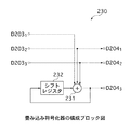
畳み込み符号化器230は、図16に示すように、排他的論理和回路231と、シフトレジスタ232とを有する。
【0018】
排他的論理和回路231は、3ビットのインターリーブデータD2031,2032,D2033を用いて排他的論理和演算を行い、演算結果を3ビットの符号化データD204のうちの1ビットの符号化データD2043として後段の多値変調マッピング回路240に出力するとともに、シフトレジスタ232に供給する。
【0019】
シフトレジスタ232は、保持している1ビットのデータを排他的論理和回路231に供給し続ける。そして、シフトレジスタ232は、クロックに同期させて、排他的論理和回路231から供給される1ビットのデータを新たに保持し、このデータを排他的論理和回路231に新たに供給する。
【0020】
このような畳み込み符号化器230は、3ビットのインターリーブデータD2031,D2032,D2033を入力すると、これらのインターリーブデータD2031,D2032,D2033に対して畳み込み演算を行い、演算結果を3ビットの符号化データD2041,D2042,D2043として後段の多値変調マッピング回路240に出力する。すなわち、畳み込み符号化器230は、内符号の符号化として符号化率が"3/3=1"の畳み込み演算を行い、生成した符号化データD204を後段の多値変調マッピング回路240に出力する。
【0021】
多値変調マッピング回路240は、畳み込み符号化器230から出力された符号化データD204を、クロックに同期させて、例えば8PSK変調方式の伝送シンボルにマッピングする。具体的には、多値変調マッピング回路240は、畳み込み符号化器230から出力された3ビットの符号化データD204を1つの伝送シンボルとしてマッピングし、1つの符号化伝送シンボルD205を生成する。多値変調マッピング回路240は、生成した符号化伝送シンボルD205を外部に出力する。
【0022】
このような符号化装置201は、畳み込み符号化器210によって外符号の符号化として符号化率が"2/3"の畳み込み演算を行い、畳み込み符号化器230によって内符号の符号化として符号化率が"1"の畳み込み演算を行うことにより、全体として、符号化率が"(2/3)×1=2/3"の縦列連接畳み込み演算を行う。この符号化装置201によって符号化され且つ変調されたデータは、無記憶通信路202を介して受信装置に出力される。
【0023】
一方、符号化装置201によるSCTCM方式の符号の復号を行う復号装置203としては、例えば図17に示すように、内符号の復号を行う軟出力復号回路250と、入力したデータの順序を元に戻すデインターリーバ260と、入力したデータの順序を並べ替えるインターリーバ270と、外符号の復号を行う軟出力復号回路280とを備えるものがある。この復号装置203は、無記憶通信路202上で発生したノイズの影響によってアナログ値をとり軟入力(soft-input)とされる受信値D206から符号化装置201における入力データD201を推定し、復号データD211として出力する。
【0024】
軟出力復号回路250は、符号化装置201における畳み込み符号化器230に対応して備えられるものであり、「Bahl, Cocke, Jelinek and Raviv, "Optimal decoding of linear codes for minimizing symbol error rate", IEEE Trans. Inf. Theory, vol. IT-20, pp. 284-287, Mar. 1974」に記載されているBCJRアルゴリズムや、このBCJRアルゴリズムを改良したアルゴリズムであって「Robertson, Villebrun and Hoeher, "A comparison of optimal and sub-optimal MAP decoding algorithms operating in the domain", IEEE Int. Conf. on Communications, pp. 1009-1013, June 1995」に記載されているMax−Log−MAPアルゴリズム又はLog−MAPアルゴリズム(以下、Max−Log−BCJRアルゴリズム又はLog−BCJRアルゴリズムという。)に基づく最大事後確率(Maximum A Posteriori probability;以下、MAPという。)復号やSOVA(Soft Output Viterbi Algorithm)復号を行うものである。軟出力復号回路250は、受信装置によって受信された軟入力の受信値D206を入力するとともに、インターリーバ270から供給された軟入力の情報ビットに対する事前確率情報(a priori probability information)D207を入力し、これらの受信値D206と事前確率情報D207とを用いて、内符号の軟出力復号を行う。そして、軟出力復号回路250は、符号の拘束条件によって求められる情報ビットに対する外部情報(extrinsic information)D208を生成し、この外部情報D208を後段のデインターリーバ260に軟出力として出力する。なお、この外部情報D208は、符号化装置201におけるインターリーバ220によってインターリーブされたインターリーブデータD203に対応するものである。
【0025】
デインターリーバ260は、符号化装置201におけるインターリーバ220によってインターリーブされたインターリーブデータD203のビット配列を、それぞれ、元の符号化データD202のビット配列に戻すように、軟出力復号回路250から出力される軟入力の外部情報D208にデインターリーブを施す。デインターリーバ260は、デインターリーブして得られたデータを後段の軟出力復号回路280における符号ビットに対する事前確率情報D209として出力する。
【0026】
インターリーバ270は、軟出力復号回路280から出力された軟入力である符号ビットに対する外部情報D210に対して、符号化装置201におけるインターリーバ220と同一の置換位置情報に基づいたインターリーブを施す。インターリーバ270は、インターリーブして得られたデータを軟出力復号回路250における情報ビットに対する事前確率情報D207として出力する。
【0027】
軟出力復号回路280は、符号化装置201における畳み込み符号化器210に対応して備えられるものであり、軟出力復号回路250と同様に、上述したBCJRアルゴリズムや、Max−Log−BCJRアルゴリズム又はLog−BCJRアルゴリズムに基づくMAP復号やSOVA復号を行うものである。軟出力復号回路280は、デインターリーバ260から出力された軟入力の符号ビットに対する事前確率情報D209を入力するとともに、図示しないが、値が"0"である情報ビットに対する事前確率情報を入力し、これらの事前確率情報を用いて、外符号の軟出力復号を行う。そして、軟出力復号回路280は、符号の拘束条件によって求められる符号ビットに対する外部情報D210を生成し、この外部情報D210をインターリーバ270に軟出力として出力する。また、軟出力復号回路280は、図示しないが、符号の拘束条件によって求められる情報ビットに対するいわゆる事後確率情報(a posteriori probability information)を生成し、この事後確率情報に基づいて、硬出力(hard-output)の復号データD211を出力する。
【0028】
このような復号装置203は、受信値D206を受信すると、軟出力復号回路250乃至軟出力復号回路280の復号動作を例えば数回乃至数十回といった所定の回数だけ反復して行い、所定の回数の復号動作の結果得られた軟出力の外部情報に基づいて、復号データD211を出力する。
【0029】
ところで、符号設計を行う際の基準の1つとして、MLクライテリア(Maximum Likelihood criteria)と称されるものがある。このMLクライテリアとは、符号の性能を表すために、ビットエラーレートの対数表示(log10 BER)と、1ビットあたりの信号対雑音電力比(Eb/N0)との関係で示される性能曲線を描いた場合に、信号対雑音電力比を高くしてもビットエラーレートの値が減少しない現象、いわゆるエラーフロア現象が生じるビットエラーレートの値を低くするための基準であり、符号全体としての重み分布の最適化を図るための基準である。
【0030】
ここで、エラーフロアは、符号の距離構造によって決まるものであることが知られている。具体的には、ブロック長がNである符号に対してエラーフロアが生じるビットエラーレートの値に支配的な項は、次式(1)に示すように表される。なお、次式(1)において、df 0は、外符号の最小距離を示し、df・effは、内符号の有効最小ユークリッド距離を示し、hm (3)は、入力ハミング距離"3"に対する最小ユークリッド距離を示すものである。また、δ2は、外符号の最小距離df 0が偶数のときには次式(2)で表され、外符号の最小距離df 0が奇数のときには次式(3)で表されるものである。
【0031】
【数1】

【数2】
【数3】
すなわち、ブロック長がNである符号に対してエラーフロアが生じるビットエラーレートの値に支配的な項は、外符号の最小距離df 0が偶数のときには、入力距離"2"に対する内符号のユークリッド距離に依存し、外符号の最小距離df 0が奇数のときには、入力距離"2"及び"3"に対する内符号のユークリッド距離に依存する。符号設計においては、このユークリッド距離を最大化することが、低いエラーフロアを得るための条件となる。
【0035】
このようなエラーフロア現象が生じるビットエラーレートの値を低くするための基準であるMLクライテリアを鑑みて符号設計を行う場合には、以下の5つの手順を踏む必要がある。
【0036】
まず、符号設計においては、いわゆるセット・パーティショニング(set partitioning)の手法等を用いて出力距離の分布を最適化し、カタストロフィックでないトレリスを作成する。
【0037】
続いて、符号設計においては、低出力距離の符号語が多数発生しないように、入力ハミング距離"1"に対する出力距離を無限大にする。すなわち、符号設計においては、例えば、トレリス上のあるステート(遷移状態)から入力ハミング距離"1"で分岐して他のステートへと到達し、さらに、入力ハミング距離"0"で元のステートへと戻るようなパスをなくし、入力ハミング距離"1"では終結しないようにする。これは、仮にこのようなパスが存在する符号を構成した場合には、インターリーバが設けられているとしても、外符号の距離が小さいときには、当該外符号がインターリーバによって並べ替えられて内符号に入力され、どのビット系列もが小さい出力距離を生成してしまうことに起因して、終結パターンが多数発生して高いエラーフロアが生じてしまう事態を招来することによるものである。
【0038】
続いて、符号設計においては、MLクライテリアにしたがう。すなわち、符号設計においては、入力距離"2"に対する内符号の出力距離を最大化する。ただし、外符号の最小距離df 0が奇数のときには、入力距離"3"に対する内符号の出力距離を最大化する。符号設計においては、このようなMLクライテリアにしたがって符号を構成した場合には、符号の重み分布が最適化され、結果的にエラーフロアを低くすることができる。
【0039】
続いて、符号設計においては、上述した入力ハミング距離"1"では終結しないようにする条件と、MLクライテリアにしたがう条件との双方にしたがって、トレリスに入力位置と出力位置とをマッピングする。
【0040】
そして、符号設計においては、畳み込み符号で表現できるように、信号点位置に符号化器の出力を割り当てる。
【0041】
符号設計においては、このような手順を踏むことにより、低いエラーフロアの符号を構成することができる。
【0042】
さて、このような手順を用いて具体的にSCTCM方式の符号設計を行った例として、「D. Divsalar, S. Dolinar and F. Pollara "Serial Concatenated Trellis Coded Modulation with Rate-1 Inner Code", GLOBECOM 2000」に記載されているものがある。以下、これについて説明する。
【0043】
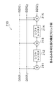
この文献においては、内符号の符号化を行う畳み込み符号化器として、図18に示す畳み込み符号化器300を用いている。すなわち、畳み込み符号化器300は、3つの排他的論理和回路301,302,303と、シフトレジスタ304とを有する。
【0044】
排他的論理和回路301は、シフトレジスタ304から供給されるデータと、入力されたインターリーブデータD3011とを用いて排他的論理和演算を行い、演算結果を3ビットの符号化データD302のうちの1ビットの符号化データD3021として図示しない後段の多値変調マッピング回路に出力する。
【0045】
排他的論理和回路302は、入力されたインターリーブデータD3011,D3012を用いて排他的論理和演算を行い、演算結果を3ビットの符号化データD302のうちの1ビットの符号化データD3022として後段の多値変調マッピング回路に出力する。
【0046】
排他的論理和回路303は、シフトレジスタ304から供給されるデータと、入力されたインターリーブデータD3011,D3012,D3013とを用いて排他的論理和演算を行い、演算結果をシフトレジスタ304に供給するとともに、3ビットの符号化データD302のうちの1ビットの符号化データD3023として後段の多値変調マッピング回路に出力する。
【0047】
シフトレジスタ304は、保持している1ビットのデータを排他的論理和回路301,303に供給し続ける。そして、シフトレジスタ304は、クロックに同期させて、排他的論理和回路303から供給される1ビットのデータを新たに保持し、このデータを排他的論理和回路301,303に新たに供給する。
【0048】
このような畳み込み符号化器300は、3ビットのインターリーブデータD3011,D3012,D3013を入力すると、これらのインターリーブデータD3011,D3012,D3013に対して畳み込み演算を行い、演算結果を3ビットの符号化データD3021,D3022,D3023として後段の多値変調マッピング回路に出力する。すなわち、畳み込み符号化器300は、内符号の符号化として符号化率が"3/3=1"の畳み込み演算を行い、符号化データD302を後段の多値変調マッピング回路に出力する。
【0049】
さらに、この文献においては、このような畳み込み符号化器300によって生成される符号化データD3021,D3022,D3023を、図19に示すように、多値変調マッピング回路によって8PSK変調方式の伝送シンボルにマッピングしている。なお、同図において、各信号点に割り当てられている伝送シンボルの値は、(D3021,D3022,D3023)を示すものである。
【0050】
この文献においては、このような畳み込み符号化器300による内符号の符号化と、多値変調マッピング回路による信号点の割り当てとを行うことにより、図20に示すトレリスを得ている。すなわち、このトレリスは、畳み込み符号化器300が有するシフトレジスタ304の内容が"0"である場合を表すステートをS0で表し、シフトレジスタ304の内容が"1"である場合を表すステートをS1で表し、さらに、各パスに付される入出力ラベルを(D3011,D3012,D3013)/(D3021,D3022,D3023)と表すものとすると、入出力ラベルが、"000/000","011/010","101/110","110/100"のものが、ステートS0からステートS0へと到達する4本のパスからなるパラレルパスに割り当てられ、入出力ラベルが、"001/001","010/011","100/111","111/101"のものが、ステートS0からステートS1へと到達する4本のパスからなるパラレルパスに割り当てられ、入出力ラベルが、"111/000","100/010","010/110","001/100"のものが、ステートS1からステートS0へと到達する4本のパスからなるパラレルパスに割り当てられ、入出力ラベルが、"110/001","101/011","011/111","000/101"のものが、ステートS1からステートS1へと到達する4本のパスからなるパラレルパスに割り当てられたものとなる。
【0051】
このようなカタストロフィックでないトレリスを作成するに至った具体的な手法について、以下説明する。
【0052】
この文献においては、カタストロフィックでないトレリスを作成するために、上述したセット・パーティショニングの手法を用いて、適切な信号点への割り当てを行っている。すなわち、この文献においては、図21(A)に示す8PSK変調方式の8個の信号点[0,1,2,3,4,5,6,7]を、同図(B)及び同図(C)にそれぞれ示すように、2つの集合A=[0,2,4,6]及びB=[1,3,5,7]に分割する。なお、以下では、集合Aの各要素を[A0,A2,A4,A6]とし、集合Bの各要素を[B1,B3,B5,B7]とする。ここで、同図(A)に示す信号点間の最小距離の2乗は、"0.59"であるのに対して、同図(B)及び同図(C)に示す信号点間の最小距離の2乗は、"2"となる。
【0053】
この集合A又は集合Bには、パラレルパスの入力ハミング距離が互いに"2"となるように信号点を割り当てる。具体的には、トレリスは、図22に示すように、入力ラベルが、"000","011","101","110"のものが、ステートS0からステートS0へと到達する4本のパスからなるパラレルパスに割り当てられ、入力ラベルが、"001","010","100","111"のものが、ステートS0からステートS1へと到達する4本のパスからなるパラレルパスに割り当てられ、入力ラベルが、"111","100","010","001"のものが、ステートS1からステートS0へと到達する4本のパスからなるパラレルパスに割り当てられ、入力ラベルが、"110","101","011","000"のものが、ステートS1からステートS1へと到達する4本のパスからなるパラレルパスに割り当てられたものとなる。
【0054】
なお、ステートS1からステートS0へと到達する4本のパスからなるパラレルパスの入力の要素は、ステートS0からステートS1へと到達する4本のパスからなるパラレルパスの入力の要素と同じであるが順序は異なるものであり、ステートS1からステートS1へと到達する4本のパスからなるパラレルパスの入力の要素は、ステートS0からステートS0へと到達する4本のパスからなるパラレルパスの入力の要素と同じものであるが順序は異なるものである。
【0055】
また、このトレリスにおいては、ステートS0からステートS0への遷移の出力と、ステートS1からステートS0への遷移の出力とを、それぞれ、集合Aとし、ステートS0からステートS1への遷移の出力と、ステートS1からステートS1への遷移の出力とを、それぞれ、集合Bとする。
【0056】
ここで、ステートS1からステートS0への遷移の出力を集合Aとし、ステートS1からステートS1への遷移の出力を集合Bとしたのは、ステートS1からステートS0への遷移の出力を集合Bとした場合には、ステートS1からステートS1への遷移の出力が集合Aとなり、ステートS0→ステートS0→ステートS0と遷移するパスの出力と、ステートS1→ステートS1→ステートS1と遷移するパスの出力とが同じものとなることから、カタストロフィックとなってしまうことによる。
【0057】
また、ステートS1からステートS0への遷移の入力の要素が、ステートS0からステートS1への遷移の入力の要素と同じものであり、ステートS1からステートS1への遷移の入力の要素が、ステートS0からステートS0への遷移の入力の要素と同じものであるのは、ステートS1からステートS0への遷移の入力の要素が、ステートS0からステートS0への遷移の入力の要素と同じものであるとした場合には、ステートS0→ステートS0→ステートS0と遷移するパスと、ステートS0→ステートS1→ステートS0と遷移するパスとに、入力ハミング距離"1"で出力ユークリッド距離が小さいものが生じてしまい、インターリーバを介して外符号と連接した際に、非常に距離が小さい符号語が多数発生してしまうことによる。
【0058】
さて、図22に示すトレリスにおけるステートS0からの分岐については、集合A又は集合Bの各要素の中で入力と出力との割り当てを任意に決定してよく、例えば図23に示すように、入力ラベルが"000"については、集合Aの要素A0を出力ラベルとして割り当て、入力ラベルが"011"については、集合Aの要素A2を出力ラベルとして割り当て、入力ラベルが"101"については、集合Aの要素A4を出力ラベルとして割り当て、入力ラベルが"110"については、集合Aの要素A6を出力ラベルとして割り当てる一方で、入力ラベルが"001"については、集合Bの要素B1を出力ラベルとして割り当て、入力ラベルが"010"については、集合Bの要素B3を出力ラベルとして割り当て、入力ラベルが"100"については、集合Bの要素B5を出力ラベルとして割り当て、入力ラベルが"111"については、集合Bの要素B7を出力ラベルとして割り当てる。
【0059】
一方、トレリスにおけるステートS1からの分岐については、入力距離"2"に対する出力距離を最大化するように決定する。
【0060】
ここで、オール"0"のパスから見た入力距離"2"のパスは、図24に示すようになる。同図における要素A?は、A0,A2,A4,A6のいずれかであることから、パスの距離の2乗和は、次式(4)に示すようになる。
【0061】
【数4】
このことから、ステートS1からステートS0へと到達する4本のパスからなるパラレルパスにおける入力距離"1"のパスについては、要素A0以外の要素を割り当てることにより、入力距離"2"に対する出力距離を最も大きくすることができることがわかる。換言すれば、ステートS1からステートS0へと到達する4本のパスからなるパラレルパスにおける唯一の入力距離"3"のパスについては、図25に示すように、要素A0を割り当てればよい。
【0063】
同様にして、要素A2,A4,A6に対応する入力についても、図26に示すように、ステートS0からステートS0へと到達する4本のパスからなるパラレルパスと、ステートS1からステートS0へと到達する4本のパスからなるパラレルパスとのうち、互いに入力距離"3"になるものが同じ信号点をとればよいことがわかる。
【0064】
また、ステートS1からステートS1へと到達する4本のパスからなるパラレルパスについては、図27を用いて考える。すなわち、このトレリスにおいては、ステートS1からステートS1へと到達する4本のパスからなるパラレルパスのうち、入力ラベルが"001"であるパスから見て入力距離"1"となるパスが、"000/B?","011/B?","101/B?"の3つだけ存在する。
【0065】
したがって、上述した議論と同様に、ステートS1からステートS1へと到達する4本のパスからなるパラレルパスのうち、出力が要素B1となるパスの入力には、入力ラベルが"001"であるパスから見て入力距離"3"となる"110"を割り当てる。また、要素B3,B5,B7に対応する入力についても同様に、ステートS0からステートS1へと到達する4本のパスからなるパラレルパスと、ステートS1からステートS1へと到達する4本のパスからなるパラレルパスとのうち、互いに入力距離"3"になるものが同じ信号点をとればよい。
【0066】
このような操作の結果、トレリスにおける各パスに付される入出力ラベルは、図28に示すようになる。
【0067】
したがって、先に図18に示した畳み込み符号化器300を内符号として用いると、集合Aにおける要素A0,A2,A4,A6は、それぞれ、"000","010","110","100"となり、集合Bにおける要素B1,B3,B5,B7は、それぞれ、"001","011","111","101"となることから、先に図20に示したカタストロフィックでないトレリスを作成することができる。
【0068】
このようなDivsalarの文献に記載された内符号と信号点のマッピングとを行う符号化装置において、入力距離"2"に対する出力距離分布は、以下のようにして求められる。
【0069】
ここで、この符号化装置は、符号化変調(Trellis Coded Modulation;以下、TCMという。)を行うものであることから、全てのパスから見た距離分布が同じでなければ、すなわち、トレリスが対称でなければ、距離分布の平均を求める必要がある。
【0070】
上述した内符号と信号点のマッピングとの組み合わせの場合には、オール"0"のパスから見た状態遷移図は、図29に示すように表される。なお、同図において、Yの乗数は入力距離を示し、Xの乗数は出力距離の2乗を示すものである。このうち、入力距離が"2"となるパスについてのみ見ると、状態遷移図は、図30に示すように表される。
【0071】
したがって、入力距離"2"に対する出力距離分布は、次式(5)で表される。
【0072】
【数5】
また、A2−A2から見た状態遷移図における入力距離が"2"となるパスを抜き出すと、図31に示すように、ステートS0からステートS1への遷移における係数が異なるものとなる。
【0074】
したがって、入力距離"2"に対する出力距離分布は、次式(6)で表される。
【0075】
【数6】
さらに、他の全てのパスは、半数ずつ、上式(5)又は上式(6)のいずれかの距離分布になっていることから、出力距離分布の平均は、次式(7)で表される。
【0077】
【数7】
【発明が解決しようとする課題】
ところで、先に図16又は図18に示した畳み込み符号化器230,300は、シフトレジスタの数、すなわち、メモリ数が"1"であることから、ステート数は"2"となる。このようなメモリ数が"1"とされる畳み込み符号化器は、入力距離"1"では終結せずに、入力距離"2"で必ず終結する。換言すれば、このような畳み込み符号化器は、入力距離が奇数の場合には終結することはない。
【0079】
ここで、上述したDivsalarの文献には、このような畳み込み符号化器を内符号の符号化器として用いた場合に、最小距離が"3"である符号を外符号として用いた場合には、内符号に対する入力距離が"3"となっても終結しないことから出力距離が大きい符号が生成され、符号全体として見たとき、外符号として、実質的に最小距離が"4"である符号を用いた場合と同じ性能になる旨が記述されている。
【0080】
これに対して、メモリ数が"2"以上である符号化器を内符号に適用した場合については、何らの議論もされていなかった。
【0081】
なお、この議論は、SCCCによる符号化についても適用できるものである。
【0082】
本発明は、このような実情に鑑みてなされたものであり、SCCCによる符号化及び/又はSCTCM方式による符号化において、メモリ数が"2"以上である符号化器を内符号に適用する際の新たな指針を提案し、性能を向上させることができる符号化装置及び符号化方法、並びにこれらの符号化装置及び符号化方法によるSCCCによる符号及び/又はSCTCM方式の符号の復号を高精度に行うことができる復号装置及び復号方法を提供することを目的とする。
【0083】
【課題を解決するための手段】
【0091】
また、上述した目的を達成する本発明にかかる符号化装置は、入力されたデータに対して縦列連接畳み込み符号化又は縦列連接符号化変調を行う符号化装置であって、入力されたデータに対して所定の符号化を行う第1の要素符号化手段と、この第1の要素符号化手段によって符号化されて生成された第1の符号化データの順序を置換して並べ替えるインターリーブ手段と、このインターリーブ手段に縦列に連接し、インターリーブ手段によって生成されたインターリーブデータに対して所定の符号化を行い、第2の符号化データを生成する第2の要素符号化手段とを備え、第2の要素符号化手段は、データを記憶する2以上の記憶素子を有し、入力距離が奇数では終結されない第2の符号化データを生成することを特徴としている。
【0092】
このような本発明にかかる符号化装置は、記憶素子数が2以上とされる第2の要素符号化手段によって内符号の符号化を行う際に、入力距離が奇数では終結されない第2の符号化データを生成するものを用いる。
【0093】
さらに、上述した目的を達成する本発明にかかる符号化方法は、入力されたデータに対して縦列連接畳み込み符号化又は縦列連接符号化変調を行う符号化方法であって、入力されたデータに対して所定の符号化を行う第1の要素符号化工程と、この第1の要素符号化工程にて符号化されて生成された第1の符号化データの順序を置換して並べ替えるインターリーブ工程と、このインターリーブ工程にて生成されたインターリーブデータに対して所定の符号化を行い、第2の符号化データを生成する第2の要素符号化工程とを備え、第2の要素符号化工程では、データを記憶する2以上の記憶素子が用いられ、入力距離が奇数では終結されない第2の符号化データが生成されることを特徴としている。
【0094】
このような本発明にかかる符号化方法は、2以上の記憶素子数を用いた内符号の符号化を行う際に、入力距離が奇数では終結されないものを用いる。
【0095】
さらにまた、上述した目的を達成する本発明にかかる復号装置は、入力されたデータに対して所定の符号化を行う第1の要素符号化手段と、この第1の要素符号化手段によって符号化されて生成された第1の符号化データの順序を置換して並べ替える第1のインターリーブ手段と、この第1のインターリーブ手段に縦列に連接し、第1のインターリーブ手段によって生成されたインターリーブデータに対して所定の符号化を行い、第2の符号化データを生成する第2の要素符号化手段とを備え、第2の要素符号化手段は、データを記憶する2以上の記憶素子を有し、入力距離が奇数では終結されない第2の符号化データを生成する符号化装置によって縦列連接畳み込み符号化又は縦列連接符号化変調が施された符号の復号を行う復号装置であって、第2の要素符号化手段に対応して備えられ、軟入力とされる受信値及び情報ビットに対する事前確率情報を入力して軟出力復号を行い、各時刻における第1の外部情報を生成する第1の軟出力復号手段と、この第1の軟出力復号手段に縦列に連接し、第1のインターリーブ手段によって並べ替えられたインターリーブデータの配列を、第1の要素符号化手段によって符号化されて生成された第1の符号化データの配列に戻すように、第1の軟出力復号手段によって生成された軟入力とされる第1の外部情報を並べ替えるデインターリーブ手段と、第1の要素符号化手段に対応して備えられ且つデインターリーブ手段に縦列に連接し、デインターリーブ手段によって生成された軟入力とされる符号ビットに対する事前確率情報と、入力された軟入力とされる情報ビットに対する事前確率情報とを用いて軟出力復号を行い、各時刻における情報ビットに対する事後確率情報及び/又は第2の外部情報を生成する第2の軟出力復号手段と、第1のインターリーブ手段と同一の置換位置情報に基づいて、第2の軟出力復号手段によって生成された軟入力とされる第2の外部情報の順序を置換して並べ替える第2のインターリーブ手段とを備え、第1の軟出力復号手段は、情報ビットに対する事前確率情報として、第2のインターリーブ手段によって生成された軟入力とされる第2の外部情報を入力することを特徴としている。
【0096】
このような本発明にかかる復号装置は、記憶素子数が2以上とされる第2の要素符号化手段によって内符号の符号化を行う際に、入力距離が奇数では終結されない第2の符号化データを生成するものを用いて生成された符号を復号する。
【0097】
また、上述した目的を達成する本発明にかかる復号方法は、入力されたデータに対して所定の符号化を行う第1の要素符号化工程と、この第1の要素符号化工程にて符号化されて生成された第1の符号化データの順序を置換して並べ替える第1のインターリーブ工程と、この第1のインターリーブ工程にて生成されたインターリーブデータに対して所定の符号化を行い、第2の符号化データを生成する第2の要素符号化工程とを備え、第2の要素符号化工程では、データを記憶する2以上の記憶素子が用いられ、入力距離が奇数では終結されない第2の符号化データが生成される符号化方法を用いて縦列連接畳み込み符号化又は縦列連接符号化変調が施された符号の復号を行う復号方法であって、第2の要素符号化工程に対応して備えられ、軟入力とされる受信値及び情報ビットに対する事前確率情報を入力して軟出力復号を行い、各時刻における第1の外部情報を生成する第1の軟出力復号工程と、第1のインターリーブ工程にて並べ替えられたインターリーブデータの配列を、第1の要素符号化工程にて符号化されて生成された第1の符号化データの配列に戻すように、第1の軟出力復号工程にて生成された軟入力とされる第1の外部情報を並べ替えるデインターリーブ工程と、第1の要素符号化工程に対応して備えられ、デインターリーブ工程にて生成された軟入力とされる符号ビットに対する事前確率情報と、入力された軟入力とされる情報ビットに対する事前確率情報とを用いて軟出力復号を行い、各時刻における情報ビットに対する事後確率情報及び/又は第2の外部情報を生成する第2の軟出力復号工程と、第1のインターリーブ工程と同一の置換位置情報に基づいて、第2の軟出力復号工程にて生成された軟入力とされる第2の外部情報の順序を置換して並べ替える第2のインターリーブ工程とを備え、第1の軟出力復号工程では、情報ビットに対する事前確率情報として、第2のインターリーブ工程にて生成された軟入力とされる第2の外部情報が入力されることを特徴としている。
【0098】
このような本発明にかかる復号方法は、2以上の記憶素子数を用いた内符号の符号化を行う際に、入力距離が奇数では終結されないものを用いて生成された符号を復号する。
【0099】
【発明の実施の形態】
以下、本発明を適用した具体的な実施の形態について図面を参照しながら詳細に説明する。
【0100】
この実施の形態は、図1に示すように、ディジタル情報を図示しない送信装置が備える符号化装置1によって符号化し、その出力を雑音のある無記憶通信路2を介して図示しない受信装置に入力して、この受信装置が備える復号装置3によって復号する通信モデルに適用したデータ送受信システムである。
【0101】
このデータ送受信システムにおいて、符号化装置1は、縦列連接畳み込み符号(Serially Concatenated Convolutional Codes;以下、SCCCという。)による符号化、及び/又は縦列連接符号化変調(Serial Concatenated Trellis Coded Modulation;以下、SCTCMという。)方式による符号化を行うものとして構成されるものである。この符号化は、いわゆるターボ符号化(Turbo coding)の一種として知られているものであって、符号化装置1は、複数の要素符号化器と、入力されたデータを並べ替えるインターリーバとを連接することにより、ターボ符号化を行うものとして構成される。この符号化装置1は、内符号の符号化を行う符号化器として、メモリ数が"2"以上とされる符号化器を用い、性能を向上させるための新たな指針を提案するものである。
【0102】
一方、復号装置3は、符号化装置1によって符号化がなされた符号の復号を行うものであって、「Bahl, Cocke, Jelinek and Raviv, "Optimal decoding of linear codes for minimizing symbol error rate", IEEE Trans. Inf. Theory, vol. IT-20, pp. 284-287, Mar. 1974」に記載されているBCJRアルゴリズム、「Robertson, Villebrun and Hoeher, "A comparison of optimal and sub-optimal MAP decoding algorithms operating in the domain", IEEE Int. Conf. on Communications, pp. 1009-1013, June 1995」に記載されているMax−Log−MAPアルゴリズム又はLog−MAPアルゴリズム(以下、Max−Log−BCJRアルゴリズム又はLog−BCJRアルゴリズムという。)に基づく最大事後確率(Maximum A Posteriori probability;以下、MAPという。)復号を行い、いわゆる事後確率情報(a posteriori probability information)に対応する軟出力(soft-output)及び/又はいわゆる外部情報(extrinsic information)を求める複数の軟出力復号回路と、入力されたデータを並べ替えるインターリーバとを連接することにより、繰り返し復号を行うものとして構成されるものである。
【0103】
なお、以下では、説明の便宜上、符号化装置1は、SCTCM方式による符号化を行うものとして説明する。また、以下では、説明の便宜上、符号化装置1における内符号の符号化を行う符号化器として、メモリ数が"2"である畳み込み符号化器を用いるものとして説明する。
【0104】
符号化装置1は、例えば図2に示すように、外符号の符号化を行う畳み込み符号化器10と、入力したデータの順序を並べ替えるインターリーバ20と、内符号の符号化を行う畳み込み符号化器30と、所定の変調方式に基づいて信号点のマッピングを行う多値変調マッピング回路40とを備える。この符号化装置1は、入力した2ビットの入力データD1に対して、符号化率が"2/3"の縦列連接畳み込み演算を行い、3ビットの符号化データD4に変換し、例えば8相位相変調方式(8-Phase Shift Keying;以下、8PSK変調方式という。)の伝送シンボルにマッピングして3ビットの1つの符号化伝送シンボルD5として出力する。
【0105】
畳み込み符号化器10は、詳細は後述するが、2ビットの入力データD1を入力すると、これらの入力データD1に対して畳み込み演算を行い、演算結果を3ビットの符号化データD2として後段のインターリーバ20に出力する。すなわち、畳み込み符号化器10は、外符号の符号化として符号化率が"2/3"の畳み込み演算を行い、生成した符号化データD2を後段のインターリーバ20に出力する。
【0106】
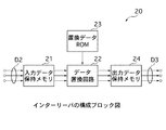
インターリーバ20は、図3に示すように、入力したデータを保持する入力データ保持メモリ21と、入力したデータの順序の並べ替え(置換)を行うデータ置換回路22と、データの置換位置情報を格納する置換データROM(Read Only Memory)23と、出力するデータを保持する出力データ保持メモリ24とを有する。
【0107】
入力データ保持メモリ21は、畳み込み符号化器10から出力された3つのビット系列からなる符号化データD2を保持し、これらの符号化データD2を所定のタイミングでデータ置換回路22に供給する。
【0108】
データ置換回路22は、置換データROM23に格納されているデータの置換位置情報に基づいて、入力データ保持メモリ21から供給された符号化データD2の順序の並べ替えを行う。データ置換回路22は、並べ替えたデータを出力データ保持メモリ24に供給する。
【0109】
置換データROM23は、例えば発生した乱数に基づいて決定されたデータの置換位置情報を格納する。すなわち、インターリーバ20は、この置換位置情報に基づいてデータのインターリーブを行うランダムインターリーバとして構成される。置換データROM23に格納されている置換位置情報は、随時データ置換回路22によって読み出される。
【0110】
出力データ保持メモリ24は、データ置換回路22から供給されるデータを保持し、これらのデータを3つのビット系列からなるインターリーブデータD3として、所定のタイミングで後段の畳み込み符号化器30に出力する。
【0111】
このようなインターリーバ20は、畳み込み符号化器10から出力された3つのビット系列からなる符号化データD2にインターリーブを施し、生成した3つのビット系列からなるインターリーブデータD3を後段の畳み込み符号化器30に出力する。
【0112】
畳み込み符号化器30は、詳細は後述するが、3ビットのインターリーブデータD3を入力すると、これらのインターリーブデータD3に対して畳み込み演算を行い、演算結果を3ビットの符号化データD4として後段の多値変調マッピング回路40に出力する。すなわち、畳み込み符号化器30は、内符号の符号化として符号化率が"3/3=1"の畳み込み演算を行い、符号化データD4を後段の多値変調マッピング回路40に出力する。
【0113】
多値変調マッピング回路40は、畳み込み符号化器30から出力された符号化データD4を、クロックに同期させて、例えば8PSK変調方式の伝送シンボルにマッピングする。具体的には、多値変調マッピング回路40は、畳み込み符号化器30から出力された3ビットの符号化データD4を1つの伝送シンボルとしてマッピングし、1つの符号化伝送シンボルD5を生成する。多値変調マッピング回路40は、生成した符号化伝送シンボルD5を外部に出力する。
【0114】
このような符号化装置1は、畳み込み符号化器10によって外符号の符号化として符号化率が"2/3"の畳み込み演算を行い、畳み込み符号化器30によって内符号の符号化として符号化率が"1"の畳み込み演算を行うことにより、全体として、符号化率が"(2/3)×1=2/3"の縦列連接畳み込み演算を行う。この符号化装置1によって符号化され且つ変調されたデータは、無記憶通信路2を介して受信装置に出力される。
【0115】
一方、復号装置3は、図4に示すように、内符号の復号を行う軟出力復号回路50と、入力したデータの順序を元に戻すデインターリーバ60と、入力したデータの順序を並べ替えるインターリーバ70と、外符号の復号を行う軟出力復号回路80と、入力したデータを2値化する2値化回路90とを備える。この復号装置3は、無記憶通信路2上で発生したノイズの影響によってアナログ値をとり軟入力(soft-input)とされる受信値D6から符号化装置1における入力データD1を推定し、復号データD13として出力する。
【0116】
軟出力復号回路50は、符号化装置1における畳み込み符号化器30に対応して備えられるものである。軟出力復号回路50は、図5に示すように、BCJRアルゴリズム、Max−Log−BCJRアルゴリズム又はLog−BCJRアルゴリズムに基づくMAP復号を行うMAP復号器51と、3つの差分器52,53,54とを有する。
【0117】
MAP復号器51は、軟入力である受信値D6と、インターリーバ70から供給された軟入力である3ビットの情報ビットに対する事前確率情報(a priori probability information)D71,D72,D73とを入力し、BCJRアルゴリズム、Max−Log−BCJRアルゴリズム又はLog−BCJRアルゴリズムに基づくMAP復号を行い、受信値D6を元に3ビットの情報ビットに対する事後確率情報D141,D142,D143を生成する。MAP復号器51は、生成した事後確率情報D141を差分器52に供給するとともに、生成した事後確率情報D142を差分器53に供給するとともに、生成した事後確率情報D143を差分器54に供給する。
【0118】
差分器52は、軟入力とされる事後確率情報D141と軟入力とされる事前確率情報D71との差分値を求め、この差分値を符号の拘束条件によって求まる3ビットの情報ビットに対する外部情報D8のうちの1ビットの外部情報D81として後段のデインターリーバ60に軟出力として出力する。
【0119】
差分器53は、軟入力とされる事後確率情報D142と軟入力とされる事前確率情報D72との差分値を求め、この差分値を3ビットの情報ビットに対する外部情報D8のうちの1ビットの外部情報D82として後段のデインターリーバ60に軟出力として出力する。
【0120】
差分器54は、軟入力とされる事後確率情報D143と軟入力とされる事前確率情報D73との差分値を求め、この差分値を3ビットの情報ビットに対する外部情報D8のうちの1ビットの外部情報D83として後段のデインターリーバ60に軟出力として出力する。
【0121】
このような軟出力復号回路50は、受信装置によって受信された軟入力の受信値D6を入力するとともに、インターリーバ70から供給された軟入力の情報ビットに対する事前確率情報D7を入力し、これらの受信値D6と事前確率情報D7とを用いて、BCJRアルゴリズム、Max−Log−BCJRアルゴリズム又はLog−BCJRアルゴリズムに基づくMAP復号を行い、内符号の軟出力復号を行う。軟出力復号回路50は、符号の拘束条件によって求められる外部情報D8を生成し、この外部情報D8を後段のデインターリーバ60に軟出力として出力する。
【0122】
具体的に説明するために、情報ビットをu、符号ビットをc、受信値D6をyとすると、軟出力復号回路50は、MAP復号器51に対して、受信値D6(y)とともに、次式(8)で表される事前確率情報D7(L(u))を入力する。
【0123】
【数8】
すなわち、軟出力復号回路50は、MAP復号器51に対して、受信値D6(y)と、情報ビットuが"1"である確率P(u=1)と情報ビットuが"0"である確率P(u=0)との比の自然対数で表される符号の拘束条件がない事前確率情報D7(L(u))とを入力する。
【0125】
続いて、軟出力復号回路50は、MAP復号器51により、BCJRアルゴリズム、Max−Log−BCJRアルゴリズム又はLog−BCJRアルゴリズムに基づくMAP復号を行い、次式(9)で表される事後確率情報D14(L*(u))を生成する。
【0126】
【数9】
すなわち、軟出力復号回路50は、MAP復号器51により、受信値D6(y)を受信した際に情報ビットuが"1"である確率P(u=1|y)と、受信値D6(y)を受信した際に情報ビットuが"0"である確率P(u=0|y)との比の自然対数で表される符号の拘束条件に基づく事後確率情報D14(L*(u))を生成する。なお、この事後確率情報D14(L*(u))は、対数尤度比(log likelihood ratio)とも呼ばれ、ここでは、受信値D6(y)を受信した際の情報ビットuの尤度を示すものである。
【0128】
そして、軟出力復号回路50は、差分器52,53,54のそれぞれにより、次式(10)で表されるように、事後確率情報D14(L*(u))と事前確率情報D7(L(u))との差分値である外部情報D8(Le(u))を求める。
【0129】
【数10】
![]()
軟出力復号回路50は、このようにして外部情報D8を生成し、この外部情報D8を後段のデインターリーバ60に軟出力として出力する。なお、この外部情報D8は、符号化装置1におけるインターリーバ20によって生成されたインターリーブデータD3に対応するものである。
【0131】
デインターリーバ60は、符号化装置1におけるインターリーバ20によってインターリーブされたインターリーブデータD3のビット配列を、それぞれ、元の符号化データD2のビット配列に戻すように、軟出力復号回路50から出力される軟入力の外部情報D8にデインターリーブを施す。デインターリーバ60は、デインターリーブして得られたデータを後段の軟出力復号回路80における符号ビットに対する事前確率情報D9として出力する。
【0132】
インターリーバ70は、軟出力復号回路80から出力された軟入力である符号ビットに対する外部情報D12に対して、符号化装置1におけるインターリーバ20と同一の置換位置情報に基づいたインターリーブを施す。インターリーバ70は、インターリーブして得られたデータを軟出力復号回路50における情報ビットに対する事前確率情報D7として出力する。
【0133】
軟出力復号回路80は、符号化装置1における畳み込み符号化器10に対応して備えられるものである。軟出力復号回路80は、図6に示すように、上述したBCJRアルゴリズム、Max−Log−BCJRアルゴリズム又はLog−BCJRアルゴリズムに基づくMAP復号を行うMAP復号器81と、5つの差分器82,83,84,85,86とを有する。
【0134】
MAP復号器81は、デインターリーバ60から出力された軟入力である3ビットの符号ビットに対する事前確率情報D91,D92,D93と、値が"0"である2ビットの情報ビットに対する事前確率情報D101,D102とを入力し、BCJRアルゴリズム、Max−Log−BCJRアルゴリズム又はLog−BCJRアルゴリズムに基づくMAP復号を行い、2ビットの情報ビットに対する事後確率情報D151,D152を生成するとともに、3ビットの符号ビットに対する事後確率情報D161,D162,D163を生成する。MAP復号器81は、生成した事後確率情報D151を差分器82に供給するとともに、生成した事後確率情報D152を差分器83に供給する。また、MAP復号器81は、生成した事後確率情報D161を差分器84に供給するとともに、生成した事後確率情報D162を差分器85に供給するとともに、生成した事後確率情報D163を差分器86に供給する。
【0135】
差分器82は、軟入力とされる事後確率情報D151と値が"0"である事前確率情報D101との差分値、すなわち、事後確率情報D151を符号の拘束条件によって求まる2ビットの情報ビットに対する外部情報D11のうちの1ビットの外部情報D111として後段の2値化回路90に軟出力として出力する。
【0136】
差分器83は、軟入力とされる事後確率情報D152と値が"0"である事前確率情報D102との差分値、すなわち、事後確率情報D152を2ビットの情報ビットに対する外部情報D11のうちの1ビットの外部情報D112として後段の2値化回路90に軟出力として出力する。
【0137】
差分器84は、軟入力とされる事後確率情報D161と軟入力とされる事前確率情報D91との差分値を求め、この差分値を3ビットの符号ビットに対する外部情報D12のうちの1ビットの外部情報D121としてインターリーバ70に軟出力として出力する。
【0138】
差分器85は、軟入力とされる事後確率情報D162と軟入力とされる事前確率情報D92との差分値を求め、この差分値を3ビットの符号ビットに対する外部情報D12のうちの1ビットの外部情報D122としてインターリーバ70に軟出力として出力する。
【0139】
差分器86は、軟入力とされる事後確率情報D163と軟入力とされる事前確率情報D93との差分値を求め、この差分値を3ビットの符号ビットに対する外部情報D12のうちの1ビットの外部情報D123としてインターリーバ70に軟出力として出力する。
【0140】
このような軟出力復号回路80は、デインターリーバ60から出力された軟入力の符号ビットに対する事前確率情報D9を入力するとともに、値が"0"である情報ビットに対する事前確率情報D10を入力し、これらの事前確率情報D9,D10を用いて、BCJRアルゴリズム、Max−Log−BCJRアルゴリズム又はLog−BCJRアルゴリズムに基づくMAP復号を行い、外符号の軟出力復号を行う。軟出力復号回路80は、符号の拘束条件によって求められる外部情報D11,D12を生成し、外部情報D11を後段の2値化回路90に軟出力として出力するとともに、外部情報D12をインターリーバ70に軟出力として出力する。
【0141】
具体的に説明するために、情報ビットをu、符号ビットをcとすると、軟出力復号回路80は、MAP復号器81に対して、次式(11)で表される事前確率情報D10(L(u))と、次式(12)で表される事前確率情報D9(L(c))とを入力する。
【0142】
【数11】
【数12】
すなわち、軟出力復号回路80は、MAP復号器81に対して、情報ビットuが"1"である確率P(u=1)と情報ビットuが"0"である確率P(u=0)との比の自然対数で表される符号の拘束条件に基づく事前確率情報D10(L(u))と、符号ビットcが"1"である確率P(c=1)と符号ビットcが"0"である確率P(c=0)との比の自然対数で表される符号の拘束条件に基づく事前確率情報D9(L(c))とを入力する。なお、上式(11)及び上式(12)における右辺に記されるべき符号の拘束条件は、ここでは省略している。また、ここでは、事前確率情報D10(L(u))は"0"であるが、これは、情報ビットuが"0"であるか"1"であるかの確率が"1/2"であることを示すことに他ならない。
【0145】
続いて、軟出力復号回路80は、MAP復号器81により、BCJRアルゴリズム、Max−Log−BCJRアルゴリズム又はLog−BCJRアルゴリズムに基づくMAP復号を行い、次式(13)で表される事後確率情報D15(L*(u))と、次式(14)で表される事後確率情報D16(L*(c))とを生成する。
【0146】
【数13】
![]()
【数14】
すなわち、軟出力復号回路80は、MAP復号器81により、情報ビットuが"1"である確率P(u=1)と情報ビットuが"0"である確率P(u=0)との比の自然対数で表される符号の拘束条件に基づく事後確率情報D15(L*(u))と、符号ビットcが"1"である確率P(c=1)と符号ビットcが"0"である確率P(c=0)との比の自然対数で表される符号の拘束条件に基づく事後確率情報D16(L*(c))とを生成する。なお、上式(13)及び上式(14)における右辺に記されるべき符号の拘束条件は、ここでは省略している。また、これらの事後確率情報D15(L*(u))と事後確率情報D16(L*(c))とは、対数尤度比とも呼ばれ、ここではそれぞれ、情報ビットuの尤度と符号ビットcの尤度とを示すものである。
【0149】
そして、軟出力復号回路80は、差分器82,83のそれぞれにより、次式(15)で表されるように、事後確率情報D15(L*(u))と事前確率情報D10(L(u))との差分値である外部情報D11(Le(u))を求めるとともに、差分器84,85,86のそれぞれにより、次式(16)で表されるように、事後確率情報D16(L*(c))と事前確率情報D9(L(c))との差分値である外部情報D12(Le(c))を求める。
【0150】
【数15】
![]()
【数16】
![]()
軟出力復号回路80は、このようにして外部情報D11,D12を生成し、外部情報D11を後段の2値化回路90に軟出力として出力するとともに、外部情報D12をインターリーバ70に軟出力として出力する。
【0153】
なお、軟出力復号回路80は、情報ビットに対する事前確率情報D10が"0"であることから、差分器82,83を必ずしも有する必要はない。
【0154】
2値化回路90は、軟出力復号回路80によって生成された事後確率情報D15を2値化し、硬出力(hard-output)の復号データD13として出力する。
【0155】
このような復号装置3は、符号化装置1における畳み込み符号化器30,10のそれぞれに対応する軟出力復号回路50,80を備えることにより、復号複雑度が高い符号を複雑度の小さい要素に分解し、軟出力復号回路50,80の間の相互作用によって特性を逐次的に向上させることができる。復号装置3は、受信値D6を入力すると、軟出力復号回路50乃至軟出力復号回路80の復号動作を例えば数回乃至数十回といった所定の回数だけ反復して行い、所定の回数の復号動作の結果得られた軟出力の事後確率情報D15に基づいて、復号データD13を出力する。
【0156】
さて、以下では、符号の性能を向上させるために提案する指針について説明する。
【0157】
まず、第1の指針について説明する。
【0158】
メモリ数が"2"である畳み込み符号化器は、入力距離が"1"である場合には、メモリ数が"1"である畳み込み符号化器と同様に、終結することはないが、入力距離が"2"である場合には、メモリ数が"1"である畳み込み符号化器のように必ず終結するとは限らず、終結しないこともある。また、メモリ数が"2"である畳み込み符号化器は、入力距離が"3"である場合には、メモリ数が"1"である畳み込み符号化器のように必ず終結しないとは限らず、終結することもある。したがって、メモリ数が"2"である畳み込み符号化器は、入力距離が奇数の場合には終結する可能性があり、入力距離が"3"以下である場合には、符号の性能が劣化することが考えられる。このような問題は、メモリ数が"2"のみならず、これ以上のメモリ数を有する符号化器を、内符号の符号化を行う符号化器として用いる場合にも生じるものである。
【0159】
そこで、第1の指針としては、内符号の符号化を行う符号化器として、メモリ数が"2"以上とされる符号化器を用いた場合に、外符号として、「内符号の最小距離符号を生じる最大の入力距離よりも大きな最小出力距離を有する符号を用いる」ことを提案する。
【0160】
具体的に、上述した畳み込み符号化器30として、生成行列G(D)が次式(17)で表される畳み込み符号化器を用いる場合について説明する。すなわち、ここでは、フィードバック多項式が2次の原始多項式(1+D+D2)で表される畳み込み符号化器を内符号の符号化を行う符号化器として用いる場合について説明する。
【0161】
【数17】
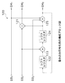
上式(17)に示す生成行列G(D)で表される畳み込み符号化器は、図7に示すように構成される。
【0163】
すなわち、同図に示す畳み込み符号化器100は、5つの排他的論理和回路101,103,104,105,106と、2つのシフトレジスタ102,107とを有する。
【0164】
排他的論理和回路101は、シフトレジスタ107から供給されるデータと、上述したインターリーバ20から出力された2ビットのインターリーブデータD31,D32とを用いて排他的論理和演算を行い、演算結果をシフトレジスタ102に供給する。
【0165】
シフトレジスタ102は、保持している1ビットのデータを排他的論理和回路103,104,105,106に供給し続ける。そして、シフトレジスタ102は、クロックに同期させて、排他的論理和回路101から供給される1ビットのデータを新たに保持し、このデータを排他的論理和回路103,104,105,106に新たに供給する。
【0166】
排他的論理和回路103は、シフトレジスタ102から供給されるデータと、インターリーバ20から出力された1ビットのインターリーブデータD31とを用いて排他的論理和演算を行い、演算結果を3ビットの符号化データD4のうちの1ビットの符号化データD41として後段の多値変調マッピング回路40に出力する。
【0167】
排他的論理和回路104は、シフトレジスタ102から供給されるデータと、インターリーバ20から出力された1ビットのインターリーブデータD32とを用いて排他的論理和演算を行い、演算結果を3ビットの符号化データD4のうちの1ビットの符号化データD42として後段の多値変調マッピング回路40に出力する。
【0168】
排他的論理和回路105は、シフトレジスタ102,107から供給されるデータと、インターリーバ20から出力された1ビットのインターリーブデータD33とを用いて排他的論理和演算を行い、演算結果を3ビットの符号化データD4のうちの1ビットの符号化データD43として後段の多値変調マッピング回路40に出力する。
【0169】
排他的論理和回路106は、シフトレジスタ102,107から供給されるデータと、インターリーバ20から出力された1ビットのインターリーブデータD33とを用いて排他的論理和演算を行い、演算結果をシフトレジスタ107に供給する。
【0170】
シフトレジスタ107は、保持している1ビットのデータを排他的論理和回路101,105,106に供給し続ける。そして、シフトレジスタ107は、クロックに同期させて、排他的論理和回路106から供給される1ビットのデータを新たに保持し、このデータを排他的論理和回路101,105,106に新たに供給する。
【0171】
このような畳み込み符号化器100は、3ビットのインターリーブデータD31,D32,D33を入力すると、これらのインターリーブデータD31,D32,D33に対して畳み込み演算を行い、演算結果を3ビットの符号化データD41,D42,D43として後段の多値変調マッピング回路40に出力する。すなわち、畳み込み符号化器100は、内符号の符号化として符号化率が"3/3=1"の畳み込み演算を行い、符号化データD4を後段の多値変調マッピング回路40に出力する。
【0172】
さらに、このような畳み込み符号化器100によって生成された符号化データD4に対して、多値変調マッピング回路40によって図8に示すような信号点のマッピングを行うものとする。なお、同図においては、各信号点に割り当てられている出力の値は、図7に示した畳み込み符号化器100から出力される3ビットの符号化データD41,D42,D43を、(D41,D42,D43)の順序で表したものである。
【0173】
このような畳み込み符号化器100による内符号の符号化と、多値変調マッピング回路40による信号点のマッピングとを行った場合、図9に示すようなトレリスが得られる。なお、同図においては、畳み込み符号化器100が有する2つのシフトレジスタ102,107の内容が"00"である場合を表すトレリスにおけるステート(遷移状態)をS00で表し、シフトレジスタ102,107の内容が"01"である場合を表すトレリスにおけるステートをS01で表し、シフトレジスタ102,107の内容が"10"である場合を表すトレリスにおけるステートをS10で表し、シフトレジスタ102,107の内容が"11"である場合を表すトレリスにおけるステートをS11で表し、各パスに付される入出力ラベルを(D31,D32,D33)/(D41,D42,D43)で表している。
【0174】
具体的には、入出力ラベルとして"000/000"が付されたステートS00からステートS00へと到達するパスと、入出力ラベルとして"101/101"が付されたステートS00からステートS01へと到達するパスとの入力距離は、"2"となり、出力距離の2乗は、図8に示した信号点の割り当てから"0.59"となる。また、入出力ラベルとして"000/000"が付されたステートS00からステートS00へと到達するパスと、入出力ラベルとして"111/111"が付されたステートS00からステートS11へと到達するパスとの入力距離は、"3"となり、出力距離の2乗は、図8に示した信号点の割り当てから"0.59"となる。さらに、入出力ラベルとして"000/000"が付されたステートS00からステートS00へと到達するパスと、入出力ラベルとして"110/000"が付されたステートS01からステートS10へと到達するパスとの入力距離は、"2"となり、出力距離の2乗は、"0"となる。さらにまた、入出力ラベルとして"000/000"が付されたステートS00からステートS00へと到達するパスと、入出力ラベルとして"001/000"が付されたステートS11からステートS10へと到達するパスとの入力距離は、"1"となり、出力距離の2乗は、"0"となる。また、入出力ラベルとして"000/000"が付されたステートS00からステートS00へと到達するパスと、入出力ラベルとして"111/000"が付されたステートS10からステートS00へと到達するパスとの入力距離は、"3"となり、出力距離の2乗は、"0"となる。
【0175】
したがって、このトレリスから明らかなように、符号の最小距離は、同図中破線部で示す2つのパスとなる。ここで、この2つのパスの入力距離は、ともに"7"であることに着目する。
【0176】
したがって、内符号の符号化を行う符号化器として、図7に示した畳み込み符号化器100を用いた場合には、外符号として、入力距離"7"よりも大きな最小距離"8"以上の符号を用いることにより、連接符号全体としての最小距離を、内符号の最小距離よりも大きくすることができることになる。したがって、符号化装置1においては、上述した畳み込み符号化器10として、このような条件を満足する符号を生成するものを設ければよい。
【0177】
このように、符号化装置1は、内符号の符号化を行う符号化器として、フィードバック多項式が原始多項式で表されるメモリ数が"2"以上とされる符号化器を用いた場合に、外符号として、内符号の最小距離符号を生じる最大の入力距離よりも大きな最小出力距離を有する符号を用いることにより、不必要に終結してしまうパターンの生成を回避することができ、符号の性能を、ビットエラーレートと1ビットあたりの信号対雑音電力比(Eb/N0)との関係で表したとき、高い信号対雑音電力比でのビットエラーレートを改善することが可能となる。
【0178】
つぎに、この第1の指針とは異なる第2の指針について説明する。
【0179】
上述した第1の指針は、内符号の符号化を行う符号化器として、メモリ数が"2"以上とされる符号化器を用いた場合には、入力距離が奇数の場合には終結する可能性があり、これを回避するために提案したものである。これに対して、ここで提案する第2の指針は、内符号の符号化を行う符号化器として、メモリ数が"2"以上とされる符号化器を用いる際に、この内符号として、「入力距離が奇数では終結されないものを用いる」ものである。
【0180】
具体的に、上述した畳み込み符号化器30として、生成行列G(D)が次式(18)で表される畳み込み符号化器を用いる場合について説明する。すなわち、ここでは、フィードバック多項式が、上式(17)に示したような原始多項式ではなく、(1+D2)で表される畳み込み符号化器を内符号の符号化を行う符号化器として用いる。
【0181】
【数18】
上式(18)に示す生成行列G(D)で表される畳み込み符号化器は、図10に示すように構成される。
【0183】
すなわち、同図に示す畳み込み符号化器120は、3つの排他的論理和回路121,123,125と、2つのシフトレジスタ122,124とを有する。
【0184】
排他的論理和回路121は、シフトレジスタ124から供給されるデータと、インターリーバ20から出力された1ビットのインターリーブデータD32とを用いて排他的論理和演算を行い、演算結果を3ビットの符号化データD4のうちの1ビットの符号化データD42として後段の多値変調マッピング回路40に出力する。
【0185】
シフトレジスタ122は、保持している1ビットのデータを排他的論理和回路123に供給し続ける。そして、シフトレジスタ122は、クロックに同期させて、排他的論理和回路125から供給される1ビットのデータを新たに保持し、このデータを排他的論理和回路123に新たに供給する。
【0186】
排他的論理和回路123は、シフトレジスタ122から供給されるデータと、インターリーバ20から出力された1ビットのインターリーブデータD32とを用いて排他的論理和演算を行い、演算結果をシフトレジスタ124に供給する。
【0187】
シフトレジスタ124は、保持している1ビットのデータを排他的論理和回路121,125に供給し続ける。そして、シフトレジスタ124は、クロックに同期させて、排他的論理和回路123から供給される1ビットのデータを新たに保持し、このデータを排他的論理和回路121,125に新たに供給する。
【0188】
排他的論理和回路125は、シフトレジスタ124から供給されるデータと、インターリーバ20から出力された2ビットのインターリーブデータD31,D33とを用いて排他的論理和演算を行い、演算結果を3ビットの符号化データD4のうちの1ビットの符号化データD43として後段の多値変調マッピング回路40に出力するとともに、シフトレジスタ122に供給する。
【0189】
このような畳み込み符号化器120は、3ビットのインターリーブデータD31,D32,D33を入力すると、1ビットのインターリーブデータD31を組織成分の符号化データD41としてそのまま後段の多値変調マッピング回路40に出力するとともに、これらのインターリーブデータD31,D32,D33に対して畳み込み演算を行い、演算結果を残りの2ビットの符号化データD42,D43として後段の多値変調マッピング回路40に出力する。すなわち、畳み込み符号化器120は、内符号の符号化として符号化率が"3/3=1"の畳み込み演算を行い、符号化データD4を後段の多値変調マッピング回路40に出力する。
【0190】
さらに、このような畳み込み符号化器120によって生成された符号化データD4に対して、多値変調マッピング回路40によって図11に示すような信号点のマッピングを行うものとする。なお、同図においても、図8と同様に、各信号点に割り当てられている出力の値は、図10に示した畳み込み符号化器120から出力される3ビットの符号化データD41,D42,D43を、(D41,D42,D43)の順序で表したものである。
【0191】
ここで、このような畳み込み符号化器120による内符号の符号化と、多値変調マッピング回路40による信号点のマッピングとの組み合わせに対して、最小距離が奇数、すなわち、nを1以上の整数としたとき最小距離が(2n+1)で表される外符号を用いると、距離の小さな連説符号の符号語を生じるのは、外符号の出力距離から"1"だけ大きい場合になる。
【0192】
したがって、符号化装置1においては、内符号の符号化を行う符号化器として、フィードバック多項式が(1+Dn)で表され、入力距離が奇数では終結されない符号を生成する符号化器を用いることにより、上述した第1の指針のように、外符号として、入力距離よりも"1"だけ大きい出力距離を有する符号を用いることなく、同等の性能を達成することができることになる。
【0193】
一般に、同じ符号化率の畳み込み符号において最小距離を増やすためには、メモリ数を増加させる必要がある。これに対して、符号化装置1は、第2の指針として示す条件を満足する符号化器を用いることにより、最小距離を増やすためにメモリ数を増加させる必要がないことから、復号コストを小さく抑制しつつ、高い信号対雑音電力比でのビットエラーレートを改善することが可能となる。
【0194】
以上説明したように、本発明の実施の形態として示したデータ送受信システムにおける符号化装置1は、内符号の符号化を行う符号化器として、メモリ数が"2"以上とされる符号化器を用いた場合には、外符号として、内符号の最小距離符号を生じる最大の入力距離よりも大きな最小出力距離を有する符号を用いることにより、高い信号対雑音電力比でのビットエラーレートを改善することができる。
【0195】
また、符号化装置1は、外符号として、内符号の最小距離符号を生じる最大の入力距離よりも大きな最小出力距離を有する符号を用いるのではなく、内符号として、フィードバック多項式が(1+Dn)で表されるような入力距離が奇数では終結されないものを用いることにより、少ない回路規模のもとに復号コストを小さく抑制しつつ、高い信号対雑音電力比でのビットエラーレートを改善することができる。
【0196】
また、復号装置3は、このような符号化装置1によって符号化がなされた符号を高精度に復号することができる。
【0197】
したがって、データ送受信システムは、符号の性能の向上を図ることができ、ユーザに優れた利便・信頼性を提供することができるものである。
【0198】
なお、本発明は、上述した実施の形態に限定されるものではない。例えば、上述した実施の形態では、符号化装置1によってSCTCM方式による符号化を行うものとして説明したが、本発明は、SCCCによる符号化を行う場合であっても適用することができる。この場合、符号化装置は、多値変調マッピングによって8PSK変調方式に基づく信号点のマッピングを行う代わりに、例えば2相位相(Binary Phase Shift Keying;BPSK)変調方式や4相位相(Quadrature Phase Shift Keying;QPSK)変調方式による変調を行うことになる。
【0199】
また、上述した実施の形態では、内符号の符号化を行う畳み込み符号化器30の具体例として、先に図7又は図10に示した畳み込み符号化器100,120を用いて説明したが、本発明は、上述した議論を逸脱しない範囲で任意のものを用いることができる。この際、本発明は、内符号に応じた信号点のマッピングを行うことはいうまでもない。また、本発明は、符号化率についても任意のものに適用可能であることはいうまでもない。
【0200】
さらに、上述した実施の形態では、復号装置における軟出力復号回路として、BCJRアルゴリズム、Max−Log−BCJRアルゴリズム又はLog−BCJRアルゴリズムに基づくMAP復号を行うものについて説明したが、本発明は、例えばいわゆるSOVA(Soft Output Viterbi Algorithm)による復号を行うといったように、他の軟出力復号にも適用可能である。
【0201】
さらにまた、上述した実施の形態では、符号化装置及び復号装置をデータ送受信システムにおける送信装置及び受信装置に適用して説明したが、本発明は、例えば、フロッピー(登録商標)ディスク、CD−ROM又はMO(Magneto Optical)といった、磁気、光又は光磁気ディスク等の記録媒体に対する記録及び/又は再生を行う記録及び/又は再生装置に適用することもできる。この場合、符号化装置によって符号化されたデータは、無記憶通信路に等価とされる記録媒体に記録され、復号装置によって復号されて再生されることになる。
【0202】
また、上述した実施の形態では、符号化装置及び復号装置ともハードウェアによって構成された装置であるものとして説明したが、これらの符号化装置及び復号装置とも、例えばワークステーションやパーソナルコンピュータといったコンピュータ装置において実行可能なソフトウェアとして実現することが可能である。以下、この例について、図12を参照して説明する。
【0203】
コンピュータ装置150は、同図に示すように、各部を統括して制御するCPU(Central Processing Unit)151と、各種プログラムを含む情報を格納する読み取り専用のROM152と、ワークエリアとして機能するRAM(Random Access Memory)153と、各種プログラムやデータ等の記録及び/又は再生を行うHDD(Hard Disk Drive)154と、これらのCPU151、ROM152、RAM153及びHDD154を接続するバス155と、CPU151、ROM152、RAM153及びHDD154と後述する表示部157、入力部158、通信部159及びドライブ160との間でデータの入出力を行うための入出力インターフェース156と、各種情報を表示する表示部157と、ユーザによる操作を受け付ける入力部158と、外部との通信を行うための通信部159と、着脱自在とされる記録媒体170に対する各種情報の記録及び/又は再生を行うドライブ160とを備える。
【0204】
CPU151は、バス155を介してROM152、RAM153及びHDD154と接続しており、これらのROM152、RAM153及びHDD154を制御する。また、CPU151は、バス155を介して入出力インターフェース156に接続しており、この入出力インターフェース156に接続されている表示部157、入力部158、通信部159及びドライブ160を制御する。さらに、CPU151は、ROM152、HDD154又はドライブ160に装着された記録媒体170に記録されている各種プログラムを実行する。
【0205】
ROM152は、各種プログラムを含む情報を格納している。このROM152に格納されている情報は、CPU151の制御の下に読み出される。
【0206】
RAM153は、CPU151が各種プログラムを実行する際のワークエリアとして機能し、CPU151の制御の下に、各種データを一時記憶する。
【0207】
HDD154は、CPU151の制御の下に、ハードディスクに対して各種プログラムやデータ等の記録及び/又は再生を行う。
【0208】
バス155は、CPU151の制御の下に、ROM152、RAM153及びHDD154から読み出された各種データ等を伝送するとともに、RAM153及びHDD154に記録する各種データ等を伝送する。
【0209】
入出力インターフェース156は、CPU151の制御の下に表示部157に各種情報を表示するためのインターフェースと、ユーザによって入力部158を介して操作された内容を示す制御信号をCPU151に対して伝送するためのインターフェースと、CPU151の制御の下に通信部159を介して外部との間でデータを入出力するためのインターフェースと、ドライブ160に装着された記録媒体170に対して各種情報の記録及び/又は再生を行うためのインターフェースとを有し、CPU151、ROM152、RAM153及びHDD154からのデータを表示部157、入力部158、通信部159及びドライブ160に対して出力したり、表示部157、入力部158、通信部159及びドライブ160からのデータをCPU151、ROM152、RAM153及びHDD154に対して入力したりする。
【0210】
表示部157は、例えばLCD(Liquid Crystal Display)からなり、CPU151の制御の下に、例えばHDD154に記録されていたデータ等の各種情報を表示する。
【0211】
入力部158は、例えばユーザによるキーボードやマウスの操作を受け付け、操作内容を示す制御信号をCPU151に対して出力する。
【0212】
通信部159は、CPU151の制御の下に、例えばネットワーク回線や衛星回線等によって外部との通信を行うインターフェースとして機能する。
【0213】
ドライブ160は、例えば、フロッピー(登録商標)ディスク、CD−ROM又はMOといった、磁気、光又は光磁気ディスク等の記録媒体170を着脱し、CPU151の制御の下に、装着された記録媒体170に対する各種情報の記録及び/又は再生を行う。
【0214】
このようなコンピュータ装置150は、CPU151によって所定のプログラムを実行することにより、上述した符号化装置1における符号化処理及び/又は復号装置3における復号処理を実現する。
【0215】
まず、コンピュータ装置150における符号化処理について説明する。
【0216】
コンピュータ装置150は、例えばユーザが符号化プログラムを実行するための所定の操作を行うと、入力部158により、操作内容を示す制御信号をCPU151に対して供給する。これに応じて、コンピュータ装置150は、CPU151により、符号化プログラムをRAM153にロードして実行し、符号化して得られた符号化伝送シンボルを通信部159を介して外部へと出力するとともに、必要に応じて、表示部157に処理結果等を表示する。
【0217】
ここで、符号化プログラムは、例えば記録媒体170によって提供されるものであって、CPU151の制御の下に、この記録媒体170から直接読み出されてもよく、ハードディスクに1度記録されたものが読み出されてもよい。また、符号化プログラムは、ROM152に予め格納されていてもよい。さらに、符号化の対象とするデータは、ここではハードディスクに記録されているものとする。なお、このデータは、上述した入力データD1に対応するものである。
【0218】
具体的には、コンピュータ装置150は、CPU151によって符号化プログラムを実行すると、CPU151の制御の下に、ハードディスクに記録されている所望のデータを読み出し、このデータに対して外符号の符号化として符号化率"2/3"の畳み込み演算を行い、上述した符号化データD2に対応する符号化データを生成する。このとき、コンピュータ装置150は、上述した第1の指針として示す条件を適用する場合には、外符号として、内符号の最小距離符号を生じる最大の入力距離よりも大きな最小出力距離を有する符号を生成する。
【0219】
続いて、コンピュータ装置150は、CPU151の制御の下に、生成した符号化データに対してインターリーブを施し、上述したインターリーブデータD3に対応するインターリーブデータを生成する。
【0220】
続いて、コンピュータ装置150は、CPU151の制御の下に、生成したインターリーブデータに対して内符号の符号化として符号化率が"3/3=1"の畳み込み演算を行い、上述した符号化データD4に対応する符号化データを生成する。このとき、コンピュータ装置150は、上述した第2の指針として示す条件を適用する場合には、内符号として、入力距離が奇数では終結されない符号を生成する。
【0221】
そして、コンピュータ装置150は、CPU151の制御の下に、生成した符号化データを例えば8PSK変調方式の伝送シンボルにマッピングし、上述した符号化伝送シンボルD5に対応する符号化伝送シンボルを生成する。
【0222】
コンピュータ装置150は、CPU151の制御の下に、生成した符号化伝送シンボルを1度ハードディスク等に記録した後、所望のタイミングで符号化伝送シンボルを読み出し、通信部159を介して外部へと出力するとともに、必要に応じて、表示部157に処理結果等を表示する。なお、生成した符号化伝送シンボルは、記録媒体170等に記録することもできる。
【0223】
このように、コンピュータ装置150は、上述した符号化装置1における符号化処理を符号化プログラムを実行することによって実現することができる。
【0224】
つぎに、コンピュータ装置150における復号処理について説明する。
【0225】
コンピュータ装置150は、例えばユーザが復号プログラムを実行するための所定の操作を行うと、入力部158により、操作内容を示す制御信号をCPU151に対して供給する。これに応じて、コンピュータ装置150は、CPU151により、復号プログラムをRAM153にロードして実行し、通信部159を介して外部から受信し、上述した受信値D6に対応するものでありハードディスク等に記録されている受信値を復号するとともに、必要に応じて、表示部157に処理結果等を表示する。
【0226】
なお、復号プログラムも、符号化プログラムと同様に、例えば記録媒体170により提供されるものであって、CPU151の制御の下に、この記録媒体170から直接読み出されてもよく、ハードディスクに1度記録されたものが読み出されてもよい。また、復号プログラムは、ROM152に予め格納されていてもよい。
【0227】
具体的には、コンピュータ装置150は、CPU151によって復号プログラムを実行すると、CPU151の制御の下に、ハードディスクから読み出した受信値、若しくは通信部159を介して受信した受信値に対して、例えば、BCJRアルゴリズム、Max−Log−BCJRアルゴリズム又はLog−BCJRアルゴリズムに基づくMAP復号を行うことによって内符号の軟出力復号を行い、上述した外部情報D8に対応する外部情報を生成する。
【0228】
続いて、コンピュータ装置150は、CPU151の制御の下に、生成した外部情報にデインターリーブを施し、上述した事前確率情報D9に対応する事前確率情報を生成する。
【0229】
続いて、コンピュータ装置150は、CPU151の制御の下に、生成した事前確率情報に対して、例えば、BCJRアルゴリズム、Max−Log−BCJRアルゴリズム又はLog−BCJRアルゴリズムに基づくMAP復号を行うことによって外符号の軟出力復号を行い、上述した外部情報D12に対応する外部情報を生成し、この外部情報にインターリーブを施し、上述した事前確率情報D7に対応する事前確率情報を生成する。
【0230】
そして、コンピュータ装置150は、CPU151の制御の下に、このような復号動作を例えば数回乃至数十回といった所定の回数だけ反復して行い、上述した事後確率情報D15に対応する所定の回数の復号動作の結果得られた軟出力の事後確率情報に基づいて、硬出力の復号データを出力する。
【0231】
コンピュータ装置150は、CPU151の制御の下に、得られた復号データをハードディスク等に記録し、必要に応じて、表示部157に処理結果等を表示する。なお、得られた復号データは、記録媒体170等に記録することもできる。
【0232】
このように、コンピュータ装置150は、上述した復号装置3における復号処理を復号プログラムを実行することによって実現することができる。
【0233】
以上のように、本発明は、その趣旨を逸脱しない範囲で適宜変更が可能であることはいうまでもない。
【0234】
【発明の効果】
【0242】
また、本発明にかかる符号化装置は、入力されたデータに対して縦列連接畳み込み符号化又は縦列連接符号化変調を行う符号化装置であって、入力されたデータに対して所定の符号化を行う第1の要素符号化手段と、この第1の要素符号化手段によって符号化されて生成された第1の符号化データの順序を置換して並べ替えるインターリーブ手段と、このインターリーブ手段に縦列に連接し、インターリーブ手段によって生成されたインターリーブデータに対して所定の符号化を行い、第2の符号化データを生成する第2の要素符号化手段とを備え、第2の要素符号化手段は、データを記憶する2以上の記憶素子を有し、入力距離が奇数では終結されない第2の符号化データを生成する。
【0243】
したがって、本発明にかかる符号化装置は、記憶素子数が2以上とされる第2の要素符号化手段によって内符号の符号化を行う際に、入力距離が奇数では終結されない第2の符号化データを生成するものを用いることにより、復号コストを小さく抑制しつつ、高い信号対雑音電力比でのビットエラーレートを改善することができ、高性能の符号化を行うことができる。
【0244】
さらに、本発明にかかる符号化方法は、入力されたデータに対して縦列連接畳み込み符号化又は縦列連接符号化変調を行う符号化方法であって、入力されたデータに対して所定の符号化を行う第1の要素符号化工程と、この第1の要素符号化工程にて符号化されて生成された第1の符号化データの順序を置換して並べ替えるインターリーブ工程と、このインターリーブ工程にて生成されたインターリーブデータに対して所定の符号化を行い、第2の符号化データを生成する第2の要素符号化工程とを備え、第2の要素符号化工程では、データを記憶する2以上の記憶素子が用いられ、入力距離が奇数では終結されない第2の符号化データが生成される。
【0245】
したがって、本発明にかかる符号化方法は、2以上の記憶素子数を用いた内符号の符号化を行う際に、入力距離が奇数では終結されないものを用いることにより、復号コストを小さく抑制しつつ、高い信号対雑音電力比でのビットエラーレートを改善することが可能となり、高性能の符号化を行うことが可能となる。
【0246】
さらにまた、本発明にかかる復号装置は、入力されたデータに対して所定の符号化を行う第1の要素符号化手段と、この第1の要素符号化手段によって符号化されて生成された第1の符号化データの順序を置換して並べ替える第1のインターリーブ手段と、この第1のインターリーブ手段に縦列に連接し、第1のインターリーブ手段によって生成されたインターリーブデータに対して所定の符号化を行い、第2の符号化データを生成する第2の要素符号化手段とを備え、第2の要素符号化手段は、データを記憶する2以上の記憶素子を有し、入力距離が奇数では終結されない第2の符号化データを生成する符号化装置によって縦列連接畳み込み符号化又は縦列連接符号化変調が施された符号の復号を行う復号装置であって、第2の要素符号化手段に対応して備えられ、軟入力とされる受信値及び情報ビットに対する事前確率情報を入力して軟出力復号を行い、各時刻における第1の外部情報を生成する第1の軟出力復号手段と、この第1の軟出力復号手段に縦列に連接し、第1のインターリーブ手段によって並べ替えられたインターリーブデータの配列を、第1の要素符号化手段によって符号化されて生成された第1の符号化データの配列に戻すように、第1の軟出力復号手段によって生成された軟入力とされる第1の外部情報を並べ替えるデインターリーブ手段と、第1の要素符号化手段に対応して備えられ且つデインターリーブ手段に縦列に連接し、デインターリーブ手段によって生成された軟入力とされる符号ビットに対する事前確率情報と、入力された軟入力とされる情報ビットに対する事前確率情報とを用いて軟出力復号を行い、各時刻における情報ビットに対する事後確率情報及び/又は第2の外部情報を生成する第2の軟出力復号手段と、第1のインターリーブ手段と同一の置換位置情報に基づいて、第2の軟出力復号手段によって生成された軟入力とされる第2の外部情報の順序を置換して並べ替える第2のインターリーブ手段とを備え、第1の軟出力復号手段は、情報ビットに対する事前確率情報として、第2のインターリーブ手段によって生成された軟入力とされる第2の外部情報を入力する。
【0247】
したがって、本発明にかかる復号装置は、記憶素子数が2以上とされる第2の要素符号化手段によって内符号の符号化を行う際に、入力距離が奇数では終結されない第2の符号化データを生成するものを用いて生成された符号を復号することにより、復号コストを小さく抑制しつつ、高い信号対雑音電力比でのビットエラーレートが改善された符号を高精度に復号することができる。
【0248】
また、本発明にかかる復号方法は、入力されたデータに対して所定の符号化を行う第1の要素符号化工程と、この第1の要素符号化工程にて符号化されて生成された第1の符号化データの順序を置換して並べ替える第1のインターリーブ工程と、この第1のインターリーブ工程にて生成されたインターリーブデータに対して所定の符号化を行い、第2の符号化データを生成する第2の要素符号化工程とを備え、第2の要素符号化工程では、データを記憶する2以上の記憶素子が用いられ、入力距離が奇数では終結されない第2の符号化データが生成される符号化方法を用いて縦列連接畳み込み符号化又は縦列連接符号化変調が施された符号の復号を行う復号方法であって、第2の要素符号化工程に対応して備えられ、軟入力とされる受信値及び情報ビットに対する事前確率情報を入力して軟出力復号を行い、各時刻における第1の外部情報を生成する第1の軟出力復号工程と、第1のインターリーブ工程にて並べ替えられたインターリーブデータの配列を、第1の要素符号化工程にて符号化されて生成された第1の符号化データの配列に戻すように、第1の軟出力復号工程にて生成された軟入力とされる第1の外部情報を並べ替えるデインターリーブ工程と、第1の要素符号化工程に対応して備えられ、デインターリーブ工程にて生成された軟入力とされる符号ビットに対する事前確率情報と、入力された軟入力とされる情報ビットに対する事前確率情報とを用いて軟出力復号を行い、各時刻における情報ビットに対する事後確率情報及び/又は第2の外部情報を生成する第2の軟出力復号工程と、第1のインターリーブ工程と同一の置換位置情報に基づいて、第2の軟出力復号工程にて生成された軟入力とされる第2の外部情報の順序を置換して並べ替える第2のインターリーブ工程とを備え、第1の軟出力復号工程では、情報ビットに対する事前確率情報として、第2のインターリーブ工程にて生成された軟入力とされる第2の外部情報が入力される。
【0249】
したがって、本発明にかかる復号方法は、2以上の記憶素子数を用いた内符号の符号化を行う際に、入力距離が奇数では終結されないものを用いて生成された符号を復号することにより、復号コストを小さく抑制しつつ、高い信号対雑音電力比でのビットエラーレートが改善された符号を高精度に復号することが可能となる。
【図面の簡単な説明】
【図1】本発明の実施の形態として示すデータ送受信システムを適用する通信モデルの構成を説明するブロック図である。
【図2】同データ送受信システムにおける符号化装置の構成を説明するブロック図である。
【図3】図2に示す符号化装置が備えるインターリーバの構成を説明するブロック図である。
【図4】同データ送受信システムにおける復号装置の構成を説明するブロック図である。
【図5】図4に示す復号装置が備える内符号の軟出力復号を行う軟出力復号回路の構成を説明するブロック図である。
【図6】図4に示す復号装置が備える外符号の軟出力復号を行う軟出力復号回路の構成を説明するブロック図である。
【図7】第1の指針として示す条件を適用した場合の図2に示す符号化装置が備える内符号の符号化を行う畳み込み符号化器の具体例としての構成を説明するブロック図である。
【図8】図2に示す符号化装置が備える多値変調マッピング回路によって行われる8PSK変調方式に基づく信号点配置を説明する図であって、図7に示す畳み込み符号化器の出力距離を説明するための図である。
【図9】図7に示す畳み込み符号化器と図8に示す信号点のマッピングとを行った場合におけるトレリスを説明する図である。
【図10】第2の指針として示す条件を適用した場合の図2に示す符号化装置が備える内符号の符号化を行う畳み込み符号化器の具体例としての構成を説明するブロック図である。
【図11】図2に示す符号化装置が備える多値変調マッピング回路によって行われる8PSK変調方式に基づく信号点配置を説明する図であって、図10に示す畳み込み符号化器の出力距離を説明するための図である。
【図12】コンピュータ装置の構成を説明するブロック図である。
【図13】通信モデルの構成を説明するブロック図である。
【図14】従来の符号化装置の構成を説明するブロック図である。
【図15】図14に示す符号化装置が備える外符号の符号化を行う畳み込み符号化器の構成を説明するブロック図である。
【図16】図14に示す符号化装置が備える内符号の符号化を行う畳み込み符号化器の構成を説明するブロック図である。
【図17】従来の復号装置の構成を説明するブロック図である。
【図18】 Divsalarの文献に記載されている内符号の符号化を行う畳み込み符号化器の構成を説明するブロック図である。
【図19】8PSK変調方式に基づく信号点配置を説明する図であって、Divsalarの文献に記載されている信号点配置を説明する図である。
【図20】図18に示す畳み込み符号化器を用いたときの図19に示す信号点配置に対応するトレリスの全部を説明する図である。
【図21】8PSK変調方式に基づく信号点配置を説明する図であって、(A)は、8個の信号点[0,1,2,3,4,5,6,7]を説明し、(B)は、セット・パーティショニングの手法を用いて分割した集合A=[0,2,4,6]を説明し、(C)は、セット・パーティショニングの手法を用いて分割した集合B=[1,3,5,7]を説明する図である。
【図22】図21に示す集合A又は集合Bに対してパラレルパスの入力ハミング距離が互いに"2"となるように信号点を割り当てたときのトレリスの全部を説明する図である。
【図23】図21に示す信号点配置に対応するトレリスの一部を説明する図であって、ステートS0からステートS0へと到達するパスと、ステートS0からステートS1へと到達するパスとを説明するための図である。
【図24】図22に示すトレリスのうち、オール"0"のパスから見た入力距離"2"のパスを抜き出したトレリスの一部を説明する図である。
【図25】図22に示すトレリスの一部を説明する図であって、ステートS0からステートS0へと到達するパスに付される入出力ラベルに応じて、ステートS1からステートS0へと到達する1本のパスに要素A0を出力とする入出力ラベルを割り当てた様子を説明するための図である。
【図26】図22に示すトレリスの一部を説明する図であって、ステートS0からステートS0へと到達するパスに付される入出力ラベルに応じて、ステートS1からステートS0へと到達する4本のパスに入出力ラベルを割り当てた様子を説明するための図である。
【図27】図22に示すトレリスの一部を説明する図であって、ステートS1からステートS1へと到達する4本のパスについて入出力ラベルを割り当てる様子を説明するための図である。
【図28】図19に示す信号点配置に対応するトレリスの全部を説明する図である。
【図29】図20に示すトレリスのうち、オール"0"のパスから見たときの状態遷移図である。
【図30】図29に示す状態遷移図のうち、入力距離が"2"となるパスについてのみ見たときの状態遷移図である。
【図31】図29に示す状態遷移図のうち、A2−A2から見たときの入力距離が"2"となるパスを抜き出した状態遷移図である。
【符号の説明】
1 符号化装置、 3 復号装置、 10,30,100,120 畳み込み符号化器、 20,70 インターリーバ、 40 多値変調マッピング回路、50,80 軟出力復号回路、 60 デインターリーバ、 90 2値化回路、 150 コンピュータ装置[0001]
BACKGROUND OF THE INVENTION
The present invention relates to an encoding apparatus and an encoding method for performing serially concatenated convolutional coding or serially concatenated code modulation on input data, and to serially concatenated convolutional encoding or cascade by these encoding apparatuses and encoding methods. The present invention relates to a decoding apparatus and a decoding method for decoding a code subjected to concatenated code modulation.
[0002]
[Prior art]
In recent years, for example, the field of communication such as mobile communication and deep space communication and the field of broadcasting such as terrestrial or satellite digital broadcasting have been remarkably advanced. Research on coding theory is also actively conducted.
[0003]
As the theoretical limit of the code performance, the Shannon limit given by the so-called Shannon (C. E. Shannon) channel coding theorem is known.
[0004]
Research on code theory is being conducted with the goal of developing codes that exhibit performance close to the Shannon limit. In recent years, for example, serially concatenated convolutional codes (hereinafter referred to as SCCC) have been developed as coding methods that exhibit performance close to the Shannon limit.
[0005]
This SCCC encoding is performed by connecting two convolutional encoders and an interleaver in series. SCCC decoding is performed by connecting two decoding circuits that output soft-output in cascade, and information is exchanged between the two decoding circuits to obtain a final decoding result. Is obtained.
[0006]
As an application of encoding by SCCC, for example, “D. Divsalar, F. Pollara,“ Serial and Hybrid Concatenation Codes with Applications ”, in Proc., Int. Symp. On Turbo Codes and Related Topics, Brest, France. , pp. 80-87, Sept. 1997 ”, is also known as a serial concatenated trellis coded modulation (hereinafter referred to as SCTCM) system. This SCTCM system is a combination of SCCC coding and multi-level modulation, and comprehensively considers the arrangement of signal points of the modulation signal and the decoding characteristics of the error correction code.
[0007]
Hereinafter, a specific example of an encoding apparatus that performs encoding by the SCTCM system and a decoding apparatus that performs decoding of codes by the SCTCM system will be described. In the following description, as shown in FIG. 13, digital information is encoded by an
[0008]
As shown in FIG. 14, for example, a
[0009]
The
[0010]
The exclusive OR
[0011]
The
[0012]
The exclusive OR
[0013]
The
[0014]
The exclusive OR
[0015]
Such a
[0016]
The
[0017]
The
[0018]
The
[0019]
The
[0020]
Such a
[0021]
The multi-level
[0022]
Such an
[0023]
On the other hand, as a
[0024]
The soft
[0025]
The
[0026]
The
[0027]
The soft
[0028]
Upon receiving the received value D206, such a
[0029]
By the way, as one of the criteria for code design, there is what is called ML criteria (Maximum Likelihood criteria). This ML criterion is a logarithmic display (log) of the bit error rate in order to express the performance of the code.10 BER) and the signal-to-noise power ratio per bit (Eb/ N0In order to reduce the bit error rate value that causes the phenomenon that the bit error rate value does not decrease even if the signal-to-noise power ratio is increased, that is, the so-called error floor phenomenon. This is a standard for optimizing the weight distribution of the entire code.
[0030]
Here, it is known that the error floor is determined by the distance structure of the code. Specifically, a term dominant in the bit error rate value at which an error floor occurs with respect to a code having a block length of N is expressed as shown in the following equation (1). In the following equation (1), df 0Indicates the minimum distance of the outer code and df ・ effDenotes the effective minimum Euclidean distance of the inner code, hm (3)Indicates the minimum Euclidean distance with respect to the input Hamming distance “3”. Also, δ2Is the minimum distance d of the outer codef 0Is an even number, it is expressed by the following equation (2), and the minimum distance d of the outer codef 0When is an odd number, it is expressed by the following equation (3).
[0031]
[Expression 1]
[Expression 2]
[Equation 3]
That is, the term dominant to the value of the bit error rate at which an error floor occurs for a code having a block length of N is the minimum distance d of the outer code.f 0Is an even number, the minimum distance d of the outer code depends on the Euclidean distance of the inner code with respect to the input distance “2”.f 0Is an odd number, it depends on the Euclidean distance of the inner code for the input distances “2” and “3”. In code design, maximizing this Euclidean distance is a condition for obtaining a low error floor.
[0035]
When code design is performed in consideration of the ML criteria, which is a criterion for reducing the bit error rate at which such an error floor phenomenon occurs, it is necessary to take the following five procedures.
[0036]
First, in code design, a so-called set partitioning technique or the like is used to optimize the output distance distribution and create a trellis that is not catastrophic.
[0037]
Subsequently, in the code design, the output distance with respect to the input Hamming distance “1” is made infinite so that a large number of code words with a low output distance are not generated. That is, in code design, for example, a certain state (transition state) on the trellis branches from an input Hamming distance “1” to reach another state, and further returns to the original state at an input Hamming distance “0”. The path that returns is eliminated and the input Hamming distance “1” is not terminated. Even if an interleaver is provided if a code having such a path exists, if the distance of the outer code is small, the outer code is rearranged by the interleaver. This is because a large error floor is generated due to the occurrence of a large number of termination patterns due to the fact that every bit sequence generates a small output distance.
[0038]
Subsequently, in code design, the ML criteria are followed. That is, in the code design, the output distance of the inner code with respect to the input distance “2” is maximized. However, the minimum distance d of the outer codef 0Is an odd number, the output distance of the inner code with respect to the input distance “3” is maximized. In code design, when a code is configured according to such ML criteria, the code weight distribution is optimized, and as a result, the error floor can be lowered.
[0039]
Subsequently, in the code design, the input position and the output position are mapped to the trellis according to both the condition that the input Hamming distance “1” does not end and the condition that follows the ML criteria.
[0040]
In code design, an encoder output is assigned to a signal point position so that it can be expressed by a convolutional code.
[0041]
In code design, a low error floor code can be configured by following such a procedure.
[0042]
As an example of concrete code design of the SCTCM system using such a procedure, “D. Divsalar, S. Dolinar and F. Pollara“ Serial Concatenated Trellis Coded Modulation with Rate-1 Inner Code ”, GLOBECOM 2000 ". This will be described below.
[0043]
In this document, a
[0044]
The exclusive OR
[0045]
The exclusive OR
[0046]
The exclusive OR
[0047]
The
[0048]
Such a
[0049]
Furthermore, in this document, encoded data D302 generated by such a
[0050]
In this document, the trellis shown in FIG. 20 is obtained by encoding the inner code by the
[0051]
A specific method that has led to the creation of such a non-catastrotic trellis will be described below.
[0052]
In this document, in order to create a trellis that is not catastrophic, assignment to an appropriate signal point is performed using the above-described set partitioning technique. That is, in this document, eight signal points [0, 1, 2, 3, 4, 5, 6, 7] of the 8PSK modulation system shown in FIG. As shown in (C), it is divided into two sets A = [0, 2, 4, 6] and B = [1, 3, 5, 7]. In the following, each element of the set A is represented by [A0, A2, A4, A6] And each element of set B is [B1, B3, B5, B7]. Here, the square of the minimum distance between the signal points shown in FIG. 9A is “0.59”, whereas the distance between the signal points shown in FIG. The square of the minimum distance is “2”.
[0053]
Signal points are assigned to the set A or the set B so that the input Hamming distances of the parallel paths are “2”. Specifically, as shown in FIG. 22, the trellis has the input labels “000”, “011”, “101”, “110”, and the state S0To state S0Assigned to a parallel path consisting of four paths arriving at and having input labels “001”, “010”, “100”, “111”0To state S1Assigned to a parallel path consisting of four paths that reach, and whose input labels are "111", "100", "010", and "001"1To state S0Assigned to a parallel path consisting of four paths that reach, and whose input labels are "110", "101", "011", "000"1To state S1Assigned to a parallel path consisting of four paths arriving at.
[0054]
State S1To state S0The input element of the parallel path consisting of four paths to reach0To state S1Is the same as the input element of the parallel path consisting of four paths to reach1To state S1The input element of the parallel path consisting of four paths to reach0To state S0This is the same as the input element of the parallel path consisting of four paths that reach the path, but the order is different.
[0055]
In this trellis, state S0To state S0Output of transition to and state S1To state S0The output of the transition to is set A and state S0To state S1Output of transition to and state S1To state S1The output of the transition to is set B.
[0056]
Where state S1To state S0The output of the transition to is set A and state S1To state S1The output of the transition to is set B as the state S1To state S0When the output of the transition to is set B, state S1To state S1The output of the transition to is set A and state S0→ State S0→ State S0Output of the transition path and state S1→ State S1→ State S1Because the output of the transition path is the same, it becomes catastrophic.
[0057]
State S1To state S0The input element of the transition to is the state S0To state S1Is the same as the input element of the transition to state S1To state S1The input element of the transition to is the state S0To state S0The same element as the input of the transition to is the state S1To state S0The input element of the transition to is the state S0To state S0If it is the same as the input element of the transition to, state S0→ State S0→ State S0And the transition path and state S0→ State S1→ State S0When the input Hamming distance is “1” and the output Euclidean distance is small, there is a large number of codewords having a very small distance when connected to the outer code through the interleaver. Because it ends up.
[0058]
Now, the state S in the trellis shown in FIG.0For the branch from, the assignment of input and output may be arbitrarily determined in each element of set A or set B. For example, as shown in FIG. Element A0Is assigned as an output label, and if the input label is “011”, the element A of the set A2Is assigned as the output label, and if the input label is "101", the element A of the set A4Is assigned as the output label, and if the input label is "110", the element A of the set A6Is assigned as an output label, while the input label is “001”, the element B of the set B1Is assigned as the output label, and if the input label is “010”, the element B of the set B3Is assigned as the output label, and if the input label is "100", the element B of the set B5Is assigned as the output label, and if the input label is "111", the element B of the set B7Is assigned as the output label.
[0059]
On the other hand, state S in the trellis1Is determined so as to maximize the output distance with respect to the input distance “2”.
[0060]
Here, the path of the input distance “2” viewed from the path of all “0” is as shown in FIG. Element A in the figure?A0, A2, A4, A6Therefore, the sum of squares of the path distance is expressed by the following equation (4).
[0061]
[Expression 4]
From this, state S1To state S0For a path with an input distance of “1” in a parallel path consisting of four paths that reach0It can be seen that the output distance with respect to the input distance “2” can be maximized by assigning elements other than. In other words, state S1To state S0As shown in FIG. 25, for the path with the only input distance “3” in the parallel path consisting of four paths that reach0Can be assigned.
[0063]
Similarly, element A2, A4, A6As for the input corresponding to the state S, as shown in FIG.0To state S0A parallel path consisting of four paths arriving at1To state S0It can be seen that among the parallel paths formed of the four paths reaching the path, those having the input distance of “3” should have the same signal point.
[0064]
State S1To state S1A parallel path composed of four paths reaching the path will be considered with reference to FIG. That is, in this trellis, state S1To state S1Of the parallel paths consisting of four paths reaching the path, the path whose input distance is “1” when viewed from the path whose input label is “001” is “000 / B?"," 011 / B?"," 101 / B?There are only three.
[0065]
Thus, similar to the discussion above, state S1To state S1Out of the parallel paths consisting of four paths that reach1For the input of the path, “110”, which is the input distance “3” as viewed from the path whose input label is “001”, is assigned. Element B3, B5, B7Similarly, the input corresponding to the state S0To state S1A parallel path consisting of four paths arriving at1To state S1Of the four parallel paths arriving at, the ones having the input distance “3” may have the same signal point.
[0066]
As a result of such an operation, the input / output labels attached to each path in the trellis are as shown in FIG.
[0067]
Therefore, if the
[0068]
In the encoding apparatus that performs the mapping between the inner code and the signal point described in the Divsalar document, the output distance distribution with respect to the input distance “2” is obtained as follows.
[0069]
Here, since this coding apparatus performs coded modulation (Trellis Coded Modulation; hereinafter referred to as TCM), the distance distribution seen from all paths is not the same, that is, the trellis is symmetric. Otherwise, it is necessary to obtain the average of the distance distribution.
[0070]
In the case of the combination of the inner code and the signal point mapping described above, the state transition diagram viewed from the path of all “0” is expressed as shown in FIG. In the figure, the multiplier of Y indicates the input distance, and the multiplier of X indicates the square of the output distance. Of these, when only the path with the input distance “2” is viewed, the state transition diagram is represented as shown in FIG.
[0071]
Therefore, the output distance distribution with respect to the input distance “2” is expressed by the following equation (5).
[0072]
[Equation 5]
A2-A2When a path with an input distance “2” in the state transition diagram seen from FIG. 31 is extracted, as shown in FIG.0To state S1The coefficient at the transition to is different.
[0074]
Therefore, the output distance distribution with respect to the input distance “2” is expressed by the following equation (6).
[0075]
[Formula 6]
Furthermore, since all other paths have a distance distribution of either the above formula (5) or the above formula (6) by half, the average of the output distance distribution is expressed by the following formula (7). Is done.
[0077]
[Expression 7]
[Problems to be solved by the invention]
By the way, in the
[0079]
Here, in the above-mentioned Divsalar document, when such a convolutional encoder is used as an inner code encoder, when a code having a minimum distance of “3” is used as an outer code, Even if the input distance to the inner code becomes “3”, it is not terminated, so that a code having a large output distance is generated. It is described that the performance is the same as when used.
[0080]
On the other hand, no discussion has been made about the case where the encoder having the number of memories of “2” or more is applied to the inner code.
[0081]
This argument can also be applied to encoding by SCCC.
[0082]
The present invention has been made in view of such circumstances, and applies an encoder having a memory number of “2” or more to an inner code in SCCC encoding and / or SCTCM encoding. The coding apparatus and the coding method capable of improving the performance and the decoding of the SCCC code and / or the SCTCM code by the coding apparatus and the coding method with high accuracy can be proposed. An object of the present invention is to provide a decoding device and a decoding method that can be performed.
[0083]
[Means for Solving the Problems]
[0091]
An encoding apparatus according to the present invention that achieves the above-described object is an encoding apparatus that performs column concatenated convolutional coding or column concatenated code modulation on input data. First element encoding means for performing predetermined encoding, and interleaving means for replacing and rearranging the order of the first encoded data generated by encoding by the first element encoding means, A second element encoding means for connecting the interleaving means in a column, performing predetermined encoding on the interleaved data generated by the interleaving means, and generating second encoded data; The element encoding means has two or more storage elements for storing data, and generates second encoded data that is not terminated when the input distance is an odd number.
[0092]
Such an encoding apparatus according to the present invention provides a second code that is not terminated when the input distance is an odd number when the inner code is encoded by the second element encoding means having two or more storage elements. The one that generates the digitized data is used.
[0093]
Furthermore, an encoding method according to the present invention that achieves the above-described object is an encoding method that performs tandem convolutional convolutional encoding or tandem concatenated code modulation on input data, and A first element encoding step that performs predetermined encoding, and an interleaving step that replaces and rearranges the order of the first encoded data generated by encoding in the first element encoding step; The second element encoding step includes performing a predetermined encoding on the interleaved data generated in the interleaving step and generating second encoded data. In the second element encoding step, Two or more storage elements that store data are used, and second encoded data that is not terminated when the input distance is an odd number is generated.
[0094]
Such an encoding method according to the present invention uses an encoding method that is not terminated when the input distance is an odd number when encoding an inner code using two or more storage elements.
[0095]
Furthermore, a decoding device according to the present invention that achieves the above-described object includes a first element encoding unit that performs predetermined encoding on input data, and an encoding by the first element encoding unit. The first interleave means that replaces and rearranges the order of the first encoded data generated in this way, and is connected to the first interleave means in a column, and the interleave data generated by the first interleave means And a second element encoding unit that performs predetermined encoding and generates second encoded data, and the second element encoding unit includes two or more storage elements that store data. A decoding device that decodes a code that has been subjected to column concatenated convolutional coding or column concatenated code modulation by an encoding device that generates second encoded data that is not terminated when the input distance is an odd number In response to the second element encoding means, the received value to be soft input and the prior probability information for the information bits are input, and soft output decoding is performed to generate first external information at each time First soft output decoding means, and an array of interleaved data that is connected in cascade to the first soft output decoding means and rearranged by the first interleaving means is encoded by the first element encoding means. Deinterleaving means for rearranging the first external information to be soft input generated by the first soft output decoding means so as to return to the first encoded data array generated by Prior probability information for code bits provided corresponding to the element encoding means and connected in series to the deinterleaving means and generated as soft inputs by the deinterleaving means, and input Second soft output decoding means for performing soft output decoding using a priori probability information for information bits to be soft input and generating posterior probability information and / or second external information for information bits at each time; Second interleaving means for permuting and rearranging the order of the second external information to be soft input generated by the second soft output decoding means based on the same replacement position information as the first interleaving means The first soft output decoding means inputs the second external information, which is a soft input generated by the second interleaving means, as the prior probability information for the information bits.
[0096]
Such a decoding apparatus according to the present invention provides a second encoding that is not terminated when the input distance is an odd number when the inner code is encoded by the second element encoding means having two or more storage elements. Decode the generated code using the one that generates the data.
[0097]
The decoding method according to the present invention that achieves the above-described object includes a first element encoding step for performing predetermined encoding on input data, and encoding in the first element encoding step. A first interleaving step of rearranging the rearranged first encoded data by rearranging the first encoded data, performing predetermined encoding on the interleaved data generated in the first interleaving step, A second element encoding step for generating encoded data of 2 in the second element encoding step. In the second element encoding step, two or more storage elements for storing data are used, and the second is not terminated when the input distance is an odd number. A decoding method for decoding a code subjected to column concatenated convolutional coding or column concatenated code modulation using an encoding method for generating encoded data of the above, and corresponds to a second element encoding step Prepared, In the first soft output decoding step for inputting the received probability value and the prior probability information for the information bits and performing the soft output decoding to generate the first external information at each time, and the first interleaving step It is generated in the first soft output decoding step so that the rearranged array of interleaved data is returned to the first encoded data sequence generated by encoding in the first element encoding step. A deinterleaving step for rearranging the first external information to be soft input and a code bit that is provided in correspondence with the first element encoding step and is to be a soft input generated in the deinterleaving step Soft output decoding is performed using the probability information and the prior probability information for the input information bits to be soft input, and the posterior probability information for the information bits at each time and / or the second external Second external information to be soft input generated in the second soft output decoding step based on the same replacement position information as in the second soft output decoding step for generating information and the first interleaving step And a second interleaving step for rearranging and rearranging the first order, and in the first soft output decoding step, the soft input generated in the second interleaving step is used as prior probability information for information bits. 2 external information is input.
[0098]
In such a decoding method according to the present invention, when encoding an inner code using two or more storage elements, a generated code is decoded using a code that is not terminated when the input distance is an odd number.
[0099]
DETAILED DESCRIPTION OF THE INVENTION
Hereinafter, specific embodiments to which the present invention is applied will be described in detail with reference to the drawings.
[0100]
In this embodiment, as shown in FIG. 1, digital information is encoded by an
[0101]
In this data transmission / reception system, the
[0102]
On the other hand, the
[0103]
In the following description, for the sake of convenience of explanation, the
[0104]
For example, as illustrated in FIG. 2, the
[0105]
Although the details will be described later, the
[0106]
As shown in FIG. 3, the
[0107]
The input
[0108]
The
[0109]
The
[0110]
The output
[0111]
Such an
[0112]
Although the details will be described later, the
[0113]
The multilevel
[0114]
Such an
[0115]
On the other hand, as shown in FIG. 4, the
[0116]
The soft
[0117]
The
[0118]
The
[0119]
The
[0120]
The
[0121]
Such a soft
[0122]
For the sake of specific explanation, if the information bit is u, the sign bit is c, and the received value D6 is y, the soft
[0123]
[Equation 8]
That is, the soft
[0125]
Subsequently, the soft
[0126]
[Equation 9]
That is, the soft
[0128]
Then, the soft
[0129]
[Expression 10]
![]()
The soft
[0131]
The
[0132]
The
[0133]
The soft
[0134]
The
[0135]
The
[0136]
The
[0137]
The
[0138]
The
[0139]
The
[0140]
Such a soft
[0141]
For specific description, if u is an information bit and c is a code bit, the soft-
[0142]
## EQU11 ##
[Expression 12]
That is, the soft-
[0145]
Subsequently, the soft
[0146]
[Formula 13]
![]()
[Expression 14]
That is, the soft
[0149]
Then, the soft
[0150]
[Expression 15]
![]()
[Expression 16]
![]()
The soft
[0153]
The soft
[0154]
The
[0155]
Such a
[0156]
Now, a guideline proposed for improving the performance of the code will be described below.
[0157]
First, the first guideline will be described.
[0158]
When the input distance is “1”, the convolutional encoder with the memory number “2” is not terminated, as with the convolutional encoder with the memory number “1”. When the distance is “2”, it is not always terminated as in the case of the convolutional encoder having the memory number “1”, and may not be terminated. In addition, a convolutional encoder with a memory number of “2” does not always end when the input distance is “3”, unlike a convolutional encoder with a memory number of “1”. Sometimes it ends. Therefore, the convolutional encoder with the memory number “2” may be terminated when the input distance is an odd number, and the code performance deteriorates when the input distance is “3” or less. It is possible. Such a problem occurs not only when the number of memories is “2” but also when an encoder having a larger number of memories is used as an encoder for encoding an inner code.
[0159]
Therefore, as a first guideline, when an encoder having a memory number of “2” or more is used as an encoder for encoding an inner code, an outer code is “minimum distance of inner code”. We propose to use a code with a minimum output distance greater than the maximum input distance that yields the code.
[0160]
Specifically, the case where a convolutional encoder whose generation matrix G (D) is represented by the following equation (17) is used as the above-described
[0161]
[Expression 17]
The convolutional encoder represented by the generator matrix G (D) shown in the above equation (17) is configured as shown in FIG.
[0163]
That is, the
[0164]
The exclusive OR
[0165]
The
[0166]
The exclusive OR
[0167]
The exclusive OR
[0168]
The exclusive OR
[0169]
The exclusive OR
[0170]
The
[0171]
Such a
[0172]
Furthermore, it is assumed that the multipoint
[0173]
When such inner code encoding by the
[0174]
Specifically, the state S with “000/000” as the input / output label00To state S00And the state S with "101/101" as the input / output label00To state S01The input distance to the path to reach is “2”, and the square of the output distance is “0.59” from the signal point assignment shown in FIG. In addition, the state S with “000/000” as the input / output label00To state S00And the state S with "111/111" as the input / output label00To state S11The input distance to the path to reach is “3”, and the square of the output distance is “0.59” from the signal point assignment shown in FIG. In addition, the state S with “000/000” as the input / output label00To state S00State S with "110/000" as the input / output label01To state S10The input distance to the path that reaches is “2”, and the square of the output distance is “0”. Furthermore, the state S with “000/000” added as the input / output label00To state S00And the state S with “001/000” as the input / output label11To state S10The input distance to the path that reaches is “1”, and the square of the output distance is “0”. In addition, the state S with “000/000” as the input / output label00To state S00State S with "111/000" as the input / output label10To state S00The input distance to the path that reaches is “3”, and the square of the output distance is “0”.
[0175]
Therefore, as is clear from this trellis, the minimum distance of the code is two paths indicated by broken lines in the figure. Here, it is noted that the input distances of these two paths are both “7”.
[0176]
Therefore, when the
[0177]
As described above, the
[0178]
Next, a second guide different from the first guide will be described.
[0179]
The first guideline described above ends when an encoder whose number of memories is “2” or more is used as an encoder for encoding an inner code, and when the input distance is an odd number. It is possible and proposed to avoid this. On the other hand, the second guideline proposed here is that when an encoder having a memory number of “2” or more is used as an encoder for encoding an inner code, “Use an input distance that is not terminated when the input distance is an odd number”.
[0180]
Specifically, a case where a convolutional encoder whose generation matrix G (D) is represented by the following equation (18) is used as the above-described
[0181]
[Formula 18]
The convolutional encoder represented by the generator matrix G (D) shown in the above equation (18) is configured as shown in FIG.
[0183]
In other words, the
[0184]
The exclusive OR
[0185]
The
[0186]
The exclusive OR
[0187]
The
[0188]
The exclusive OR
[0189]
Such a
[0190]
Furthermore, it is assumed that the multipoint
[0191]
Here, the minimum distance is an odd number, i.e., n is an integer greater than or equal to the combination of the inner code encoding by the
[0192]
Therefore, in the
[0193]
In general, it is necessary to increase the number of memories in order to increase the minimum distance in convolutional codes having the same coding rate. On the other hand, since the
[0194]
As described above, the
[0195]
Also, the
[0196]
The
[0197]
Therefore, the data transmission / reception system can improve the code performance, and can provide the user with excellent convenience and reliability.
[0198]
The present invention is not limited to the embodiment described above. For example, in the above-described embodiment, the
[0199]
In the above-described embodiment, as a specific example of the
[0200]
Further, in the above-described embodiment, the soft output decoding circuit in the decoding device has been described as performing the MAP decoding based on the BCJR algorithm, the Max-Log-BCJR algorithm, or the Log-BCJR algorithm. The present invention can also be applied to other soft output decoding such as decoding by SOVA (Soft Output Viterbi Algorithm).
[0201]
Furthermore, in the above-described embodiment, the encoding device and the decoding device have been described as being applied to a transmission device and a reception device in a data transmission / reception system. However, the present invention is, for example, a floppy (registered trademark) disk, a CD-ROM. Alternatively, the present invention can be applied to a recording and / or reproducing apparatus that performs recording and / or reproduction on a recording medium such as a magnetic, optical, or magneto-optical disk such as MO (Magneto Optical). In this case, the data encoded by the encoding device is recorded on a recording medium equivalent to the memoryless communication path, and is decoded and reproduced by the decoding device.
[0202]
In the above-described embodiments, the encoding apparatus and the decoding apparatus have been described as hardware apparatuses. However, both the encoding apparatus and the decoding apparatus are computer apparatuses such as workstations and personal computers. It can be realized as executable software. Hereinafter, this example will be described with reference to FIG.
[0203]
As shown in the figure, the
[0204]
The
[0205]
The
[0206]
The
[0207]
The
[0208]
Under the control of the
[0209]
The input /
[0210]
The
[0211]
The
[0212]
The
[0213]
The
[0214]
Such a
[0215]
First, the encoding process in the
[0216]
For example, when the user performs a predetermined operation for executing the encoding program, the
[0217]
Here, the encoding program is provided by, for example, the
[0218]
Specifically, when the
[0219]
Subsequently, the
[0220]
Subsequently, under the control of the
[0221]
Then, under the control of the
[0222]
The
[0223]
Thus, the
[0224]
Next, a decoding process in the
[0225]
For example, when the user performs a predetermined operation for executing the decryption program, the
[0226]
Similar to the encoding program, the decoding program is also provided by, for example, the
[0227]
Specifically, when the
[0228]
Subsequently, under the control of the
[0229]
Subsequently, under the control of the
[0230]
Then, under the control of the
[0231]
The
[0232]
As described above, the
[0233]
As described above, it goes without saying that the present invention can be modified as appropriate without departing from the spirit of the present invention.
[0234]
【The invention's effect】
[0242]
An encoding apparatus according to the present invention is an encoding apparatus that performs column concatenated convolutional coding or column concatenated code modulation on input data, and performs predetermined encoding on the input data. First element encoding means for performing, interleaving means for replacing the order of the first encoded data generated by encoding by the first element encoding means, and rearranging the interleave means in a column A second element encoding unit that performs contiguous encoding on the interleaved data generated by the interleaving unit and generates second encoded data; and the second element encoding unit includes: Second encoded data that has two or more storage elements for storing data and is not terminated when the input distance is an odd number is generated.
[0243]
Therefore, the encoding apparatus according to the present invention provides the second encoding that is not terminated when the input distance is an odd number when the inner code is encoded by the second element encoding means having two or more storage elements. By using the one that generates data, it is possible to improve the bit error rate at a high signal-to-noise power ratio while suppressing the decoding cost to be small, and to perform high-performance encoding.
[0244]
Furthermore, an encoding method according to the present invention is an encoding method for performing serially concatenated convolutional encoding or serially concatenated encoded modulation on input data, and performs predetermined encoding on the input data. A first element encoding step to be performed, an interleaving step for replacing the order of the first encoded data generated by encoding in the first element encoding step and rearranging, and in the interleaving step A second element encoding step for performing predetermined encoding on the generated interleaved data and generating second encoded data, and in the second element encoding step, two or more for storing data The second encoded data that is not terminated when the input distance is an odd number is generated.
[0245]
Therefore, in the encoding method according to the present invention, when encoding the inner code using the number of storage elements of 2 or more, the decoding cost is suppressed to a low level by using the one that is not terminated when the input distance is an odd number. The bit error rate at a high signal-to-noise power ratio can be improved, and high-performance encoding can be performed.
[0246]
Furthermore, the decoding apparatus according to the present invention includes a first element encoding unit that performs predetermined encoding on input data, and a first element encoded and generated by the first element encoding unit. First interleaving means for rearranging and rearranging one encoded data, and a predetermined encoding for interleaved data connected to the first interleaving means in a column and generated by the first interleaving means And second element encoding means for generating second encoded data, and the second element encoding means has two or more storage elements for storing data, and if the input distance is an odd number A decoding device that decodes a code that has been subjected to column concatenated convolutional coding or column concatenated code modulation by an encoding device that generates second encoded data that is not terminated, and includes a second element encoding The first soft output decoding means is provided corresponding to the stage and performs the soft output decoding by inputting the received value to be the soft input and the prior probability information for the information bits, and generates the first external information at each time The first soft output decoding means is connected to the first soft output decoding means in a column, and the first interleaving data array rearranged by the first interleaving means is encoded by the first element encoding means and is generated. Corresponding to deinterleaving means for rearranging the first external information to be soft input generated by the first soft output decoding means so as to return to the array of encoded data, and first element encoding means Pre-probability information for code bits that are provided and connected to the deinterleaving means in series and are generated by the deinterleaving means, and information that is input as the soft input Second soft output decoding means for performing soft output decoding using a priori probability information for a signal and generating posterior probability information and / or second external information for information bits at each time, and first interleaving means And second interleaving means for replacing and rearranging the order of the second external information to be soft input generated by the second soft output decoding means based on the same replacement position information as The soft output decoding means inputs the second external information as the soft input generated by the second interleaving means as the prior probability information for the information bits.
[0247]
Therefore, the decoding apparatus according to the present invention provides the second encoded data that is not terminated when the input distance is an odd number when the inner code is encoded by the second element encoding means having two or more storage elements. By decoding the code generated using the one that generates the signal, it is possible to decode the code with improved bit error rate at a high signal-to-noise power ratio with high accuracy while suppressing the decoding cost small .
[0248]
The decoding method according to the present invention includes a first element encoding process for performing predetermined encoding on input data, and a first element encoded and generated in the first element encoding process. A first interleaving step for rearranging and rearranging the order of the first encoded data, and performing a predetermined encoding on the interleaved data generated in the first interleaving step, and converting the second encoded data into A second element encoding step for generating, wherein the second element encoding step uses two or more storage elements for storing data, and generates second encoded data that is not terminated when the input distance is an odd number A decoding method for decoding a code that has been subjected to tandem convolutional convolutional coding or tandem concatenated code modulation using an encoding method that is provided, corresponding to the second element encoding step, and includes a soft input Received value and First probability output for information bits is input to perform soft output decoding, and first soft output decoding step for generating first external information at each time, and interleaved data rearranged in the first interleaving step The soft input generated in the first soft output decoding step is returned to the array of the first encoded data generated by encoding in the first element encoding step. A prior intervening probability information for a code bit that is provided as a soft input generated in the deinterleaving process and is provided in correspondence with the deinterleaving process for rearranging the 1 external information and the first element encoding process. Soft output decoding is performed using a priori probability information for information bits to be soft input, and second soft information for generating posterior probability information and / or second external information for information bits at each time is generated. Based on the same replacement position information as in the force decoding step and the first interleaving step, the order of the second external information that is the soft input generated in the second soft output decoding step is replaced and rearranged. A second interleaving step, and in the first soft output decoding step, second external information that is a soft input generated in the second interleaving step is input as prior probability information for the information bits. .
[0249]
Therefore, in the decoding method according to the present invention, when encoding an inner code using the number of storage elements of 2 or more, by decoding a code generated using an input distance that is not terminated with an odd number, It is possible to accurately decode a code with an improved bit error rate at a high signal-to-noise power ratio while suppressing the decoding cost to a low level.
[Brief description of the drawings]
FIG. 1 is a block diagram illustrating a configuration of a communication model to which a data transmission / reception system shown as an embodiment of the present invention is applied.
FIG. 2 is a block diagram illustrating a configuration of an encoding device in the data transmission / reception system.
FIG. 3 is a block diagram illustrating a configuration of an interleaver included in the encoding device shown in FIG.
FIG. 4 is a block diagram illustrating a configuration of a decoding device in the data transmission / reception system.
5 is a block diagram illustrating a configuration of a soft output decoding circuit that performs soft output decoding of an inner code included in the decoding device illustrated in FIG. 4; FIG.
6 is a block diagram illustrating a configuration of a soft output decoding circuit that performs soft output decoding of an outer code included in the decoding device illustrated in FIG. 4; FIG.
7 is a block diagram illustrating a configuration as a specific example of a convolutional encoder that encodes an inner code included in the encoding device illustrated in FIG. 2 when the condition indicated as the first guideline is applied. FIG.
8 is a diagram for explaining signal point arrangement based on an 8PSK modulation method performed by a multi-level modulation mapping circuit included in the encoding device shown in FIG. 2, and explaining the output distance of the convolutional encoder shown in FIG. 7; It is a figure for doing.
9 is a diagram for explaining a trellis when the convolutional encoder shown in FIG. 7 and the signal point mapping shown in FIG. 8 are performed.
FIG. 10 is a block diagram illustrating a configuration as a specific example of a convolutional encoder that performs encoding of an inner code included in the encoding device illustrated in FIG. 2 when a condition indicated as a second guideline is applied.
11 is a diagram for explaining signal point arrangement based on the 8PSK modulation method performed by the multi-level modulation mapping circuit included in the encoding device shown in FIG. 2, and explaining the output distance of the convolutional encoder shown in FIG. 10; It is a figure for doing.
FIG. 12 is a block diagram illustrating a configuration of a computer device.
FIG. 13 is a block diagram illustrating a configuration of a communication model.
FIG. 14 is a block diagram illustrating a configuration of a conventional encoding device.
15 is a block diagram illustrating a configuration of a convolutional encoder that performs encoding of an outer code included in the encoding device illustrated in FIG.
16 is a block diagram illustrating a configuration of a convolutional encoder that performs encoding of an inner code included in the encoding device illustrated in FIG.
FIG. 17 is a block diagram illustrating a configuration of a conventional decoding device.
FIG. 18 is a block diagram illustrating a configuration of a convolutional encoder that performs encoding of an inner code described in the document of Divsalar.
FIG. 19 is a diagram for explaining signal point arrangements based on the 8PSK modulation method, and for explaining signal point arrangements described in Divsalar literature;
20 is a diagram for explaining all of the trellis corresponding to the signal point arrangement shown in FIG. 19 when the convolutional encoder shown in FIG. 18 is used.
FIG. 21 is a diagram for explaining signal point arrangement based on the 8PSK modulation method, in which (A) explains eight signal points [0, 1, 2, 3, 4, 5, 6, 7]. , (B) explains the set A = [0, 2, 4, 6] divided using the set partitioning technique, and (C) shows the set divided using the set partitioning technique. It is a figure explaining B = [1,3,5,7].
22 is a diagram for explaining all of the trellis when signal points are assigned to the set A or the set B shown in FIG. 21 such that the input Hamming distances of the parallel paths are “2” with respect to each other.
23 is a diagram for explaining a part of a trellis corresponding to the signal point arrangement shown in FIG.0To state S0The path to reach and state S0To state S1It is a figure for demonstrating the path | route which reaches | attains.
24 is a diagram for explaining a part of the trellis extracted from the path of the input distance “2” viewed from the path of all “0” in the trellis illustrated in FIG. 22;
25 is a diagram for explaining a part of the trellis shown in FIG.0To state S0Depending on the I / O label attached to the path that reaches1To state S0Element A in a single path to reach0It is a figure for demonstrating a mode that the input-output label which outputs is assigned.
26 is a diagram for explaining a part of the trellis shown in FIG.0To state S0Depending on the I / O label attached to the path that reaches1To state S0It is a figure for demonstrating a mode that the input-output label was allocated to four path | routes which reach | attain.
27 is a diagram for explaining a part of the trellis shown in FIG.1To state S1It is a figure for demonstrating a mode that an input / output label is allocated about four path | routes which reach | attain.
28 is a diagram for explaining all of the trellis corresponding to the signal point arrangement shown in FIG. 19;
29 is a state transition diagram when seen from the path of all “0” s in the trellis shown in FIG. 20;
30 is a state transition diagram when only a path having an input distance of “2” in the state transition diagram shown in FIG. 29 is viewed.
31 is a diagram showing the state transition diagram A shown in FIG.2-A2FIG. 6 is a state transition diagram in which a path having an input distance “2” when extracted from FIG.
[Explanation of symbols]
DESCRIPTION OF
Claims (9)
入力されたデータに対して所定の符号化を行う第1の要素符号化手段と、
上記第1の要素符号化手段によって符号化されて生成された第1の符号化データの順序を置換して並べ替えるインターリーブ手段と、
上記インターリーブ手段に縦列に連接し、上記インターリーブ手段によって生成されたインターリーブデータに対して所定の符号化を行い、第2の符号化データを生成する第2の要素符号化手段とを備え、
上記第2の要素符号化手段は、データを記憶する2以上の記憶素子を有し、入力距離が奇数では終結されない上記第2の符号化データを生成すること
を特徴とする符号化装置。An encoding device that performs column concatenated convolutional coding or column concatenated code modulation on input data,
First element encoding means for performing predetermined encoding on input data;
Interleaving means for replacing and rearranging the order of the first encoded data generated by encoding by the first element encoding means;
A second element encoding unit connected to the interleaving unit in a column, performing predetermined encoding on the interleaved data generated by the interleaving unit, and generating second encoded data;
The encoding device characterized in that the second element encoding means has two or more storage elements for storing data, and generates the second encoded data that is not terminated when the input distance is an odd number.
を特徴とする請求項1記載の符号化装置。It said second element encoding means encoding apparatus according to claim 1, wherein the feedback polynomial in the generation matrix is represented by (1 + Dn).
を特徴とする請求項1記載の符号化装置。The first element encoding means and said second element encoding means, respectively, the encoding apparatus according to claim 1, wherein the performing convolutional coding.
を特徴とする請求項1記載の符号化装置。Coding according to claim 1, characterized in that it comprises a mapping means for mapping the second group of encoded data generated is encoded by the second element encoding means transmission symbol of a predetermined modulation scheme apparatus.
を特徴とする請求項4記載の符号化装置。The encoding apparatus according to claim 4 , wherein the mapping means performs modulation by an eight-phase modulation method.
入力されたデータに対して所定の符号化を行う第1の要素符号化工程と、
上記第1の要素符号化工程にて符号化されて生成された第1の符号化データの順序を置換して並べ替えるインターリーブ工程と、
上記インターリーブ工程にて生成されたインターリーブデータに対して所定の符号化を行い、第2の符号化データを生成する第2の要素符号化工程とを備え、
上記第2の要素符号化工程では、データを記憶する2以上の記憶素子が用いられ、入力距離が奇数では終結されない上記第2の符号化データが生成されること
を特徴とする符号化方法。An encoding method for performing column concatenated convolutional coding or column concatenated code modulation on input data,
A first element encoding step for performing predetermined encoding on input data;
An interleaving step of permuting the first encoded data generated by encoding in the first element encoding step by replacing the order;
A second element encoding step for performing predetermined encoding on the interleaved data generated in the interleaving step and generating second encoded data,
In the second element encoding step, two or more storage elements that store data are used, and the second encoded data that is not terminated when the input distance is an odd number is generated.
上記第2の要素符号化手段に対応して備えられ、軟入力とされる受信値及び情報ビットに対する事前確率情報を入力して軟出力復号を行い、各時刻における第1の外部情報を生成する第1の軟出力復号手段と、
上記第1の軟出力復号手段に縦列に連接し、上記第1のインターリーブ手段によって並べ替えられた上記インターリーブデータの配列を、上記第1の要素符号化手段によって符号化されて生成された上記第1の符号化データの配列に戻すように、上記第1の軟出力復号手段によって生成された軟入力とされる上記第1の外部情報を並べ替えるデインターリーブ手段と、
上記第1の要素符号化手段に対応して備えられ且つ上記デインターリーブ手段に縦列に連接し、上記デインターリーブ手段によって生成された軟入力とされる符号ビットに対する事前確率情報と、入力された軟入力とされる情報ビットに対する事前確率情報とを用いて軟出力復号を行い、各時刻における情報ビットに対する事後確率情報及び/又は第2の外部情報を生成する第2の軟出力復号手段と、
上記第1のインターリーブ手段と同一の置換位置情報に基づいて、上記第2の軟出力復号手段によって生成された軟入力とされる上記第2の外部情報の順序を置換して並べ替える第2のインターリーブ手段とを備え、
上記第1の軟出力復号手段は、上記情報ビットに対する事前確率情報として、上記第2のインターリーブ手段によって生成された軟入力とされる上記第2の外部情報を入力すること
を特徴とする復号装置。The first element encoding means for performing predetermined encoding on the input data and the order of the first encoded data generated by encoding by the first element encoding means are replaced. First interleaving means for rearranging, and the first interleaving means connected in a column, the interleaved data generated by the first interleaving means is subjected to predetermined encoding, and the second encoded data is Second element encoding means for generating, wherein the second element encoding means has two or more storage elements for storing data, and the second encoded data is not terminated when the input distance is an odd number. A decoding device that decodes a code that has been subjected to column concatenated convolutional coding or column concatenated code modulation by an encoding device that generates
Provided in correspondence with the second element encoding means, the received value to be soft input and the prior probability information for the information bits are input, and soft output decoding is performed to generate first external information at each time First soft output decoding means;
The first soft output decoding means connected to the first soft output decoding means in a column and generated by encoding the interleaved data array rearranged by the first interleaving means by the first element encoding means. Deinterleaving means for rearranging the first external information to be soft input generated by the first soft output decoding means so as to return to an array of one encoded data;
Pre-probability information for code bits that are provided corresponding to the first element encoding means and are connected in series to the deinterleaving means and are soft inputs generated by the deinterleaving means; Second soft output decoding means for performing soft output decoding using a priori probability information for information bits to be input, and generating posterior probability information and / or second external information for information bits at each time;
Based on the same replacement position information as the first interleave means, the second external information to be soft input generated by the second soft output decoding means is replaced and rearranged. Interleaving means,
The first soft output decoding means inputs the second external information, which is a soft input generated by the second interleave means, as prior probability information for the information bits. .
を特徴とする請求項7記載の復号装置。The decoding apparatus according to claim 7 , wherein a probability of passing through an arbitrary state is obtained based on the received value, and the code is repeatedly decoded using the probability.
上記第2の要素符号化工程に対応して備えられ、軟入力とされる受信値及び情報ビットに対する事前確率情報を入力して軟出力復号を行い、各時刻における第1の外部情報を生成する第1の軟出力復号工程と、
上記第1のインターリーブ工程にて並べ替えられた上記インターリーブデータの配列を、上記第1の要素符号化工程にて符号化されて生成された上記第1の符号化データの配列に戻すように、上記第1の軟出力復号工程にて生成された軟入力とされる上記第1の外部情報を並べ替えるデインターリーブ工程と、
上記第1の要素符号化工程に対応して備えられ、上記デインターリーブ工程にて生成された軟入力とされる符号ビットに対する事前確率情報と、入力された軟入力とされる情報ビットに対する事前確率情報とを用いて軟出力復号を行い、各時刻における情報ビットに対する事後確率情報及び/又は第2の外部情報を生成する第2の軟出力復号工程と、
上記第1のインターリーブ工程と同一の置換位置情報に基づいて、上記第2の軟出力復号工程にて生成された軟入力とされる上記第2の外部情報の順序を置換して並べ替える第2のインターリーブ工程とを備え、
上記第1の軟出力復号工程では、上記情報ビットに対する事前確率情報として、上記第2のインターリーブ工程にて生成された軟入力とされる上記第2の外部情報が入力されること
を特徴とする復号方法。The first element encoding step for performing predetermined encoding on the input data and the order of the first encoded data generated by encoding in the first element encoding step are replaced. A first interleaving step for rearranging and a second element encoding step for performing predetermined encoding on the interleaved data generated in the first interleaving step and generating second encoded data, And the second element encoding step uses an encoding method in which two or more storage elements that store data are used and the second encoded data that is not terminated when the input distance is an odd number is generated. A decoding method for decoding a code subjected to column concatenated convolutional coding or column concatenated code modulation,
Provided in correspondence with the second element encoding step, the reception value to be soft input and the prior probability information for the information bits are input, and soft output decoding is performed to generate first external information at each time A first soft output decoding step;
The array of the interleaved data rearranged in the first interleave process is returned to the array of the first encoded data generated by encoding in the first element encoding process. A deinterleaving step of rearranging the first external information to be the soft input generated in the first soft output decoding step;
Prior probability information for code bits to be soft inputs and corresponding to input information bits to be soft inputs, provided corresponding to the first element encoding step and generated in the deinterleaving step A second soft output decoding step that performs soft output decoding using information and generates posterior probability information and / or second external information for information bits at each time;
A second one that replaces and rearranges the order of the second external information that is the soft input generated in the second soft output decoding step, based on the same replacement position information as in the first interleaving step; With an interleaving process
In the first soft output decoding step, the second external information, which is a soft input generated in the second interleaving step, is input as prior probability information for the information bits. Decryption method.
Priority Applications (2)
| Application Number | Priority Date | Filing Date | Title |
|---|---|---|---|
| JP2002131964A JP3823315B2 (en) | 2002-05-07 | 2002-05-07 | Encoding apparatus, encoding method, decoding apparatus, and decoding method |
| US10/428,905 US6765507B2 (en) | 2002-05-07 | 2003-05-02 | Encoding device and method and decoding device and method |
Applications Claiming Priority (1)
| Application Number | Priority Date | Filing Date | Title |
|---|---|---|---|
| JP2002131964A JP3823315B2 (en) | 2002-05-07 | 2002-05-07 | Encoding apparatus, encoding method, decoding apparatus, and decoding method |
Publications (3)
| Publication Number | Publication Date |
|---|---|
| JP2003324357A JP2003324357A (en) | 2003-11-14 |
| JP2003324357A5 JP2003324357A5 (en) | 2005-04-14 |
| JP3823315B2 true JP3823315B2 (en) | 2006-09-20 |
Family
ID=29544365
Family Applications (1)
| Application Number | Title | Priority Date | Filing Date |
|---|---|---|---|
| JP2002131964A Expired - Fee Related JP3823315B2 (en) | 2002-05-07 | 2002-05-07 | Encoding apparatus, encoding method, decoding apparatus, and decoding method |
Country Status (2)
| Country | Link |
|---|---|
| US (1) | US6765507B2 (en) |
| JP (1) | JP3823315B2 (en) |
Families Citing this family (32)
| Publication number | Priority date | Publication date | Assignee | Title |
|---|---|---|---|---|
| JP2004146982A (en) * | 2002-10-23 | 2004-05-20 | Sony Corp | Coder, coding method, program for the coding method, decoder, decoding method, and program for the decoding method |
| US7200798B2 (en) * | 2003-06-26 | 2007-04-03 | Lucent Technologies Inc. | Unified serial/parallel concatenated convolutional code decoder architecture and method |
| US7391816B2 (en) * | 2003-09-17 | 2008-06-24 | Intel Corporation | Decoding upstream V.92-encoded signals |
| US7490284B2 (en) * | 2005-02-03 | 2009-02-10 | Broadcom Corporation | Meta-Viterbi algorithm for use in communication systems |
| US7469373B2 (en) * | 2005-02-17 | 2008-12-23 | Broadcom Corporation | Application of a Meta-Viterbi algorithm for communication systems without intersymbol interference |
| US7730384B2 (en) * | 2005-02-28 | 2010-06-01 | Agere Systems Inc. | Method and apparatus for evaluating performance of a read channel |
| US7620881B2 (en) * | 2005-03-09 | 2009-11-17 | Harris Corporation | System and method for communicating data using iterative equalizing and decoding and recursive inner code |
| US7793169B2 (en) * | 2005-10-19 | 2010-09-07 | Telefonaktiebolaget Lm Ericsson (Publ) | Intelligent table-driven interleaving |
| US8259867B2 (en) * | 2008-01-04 | 2012-09-04 | Qualcomm Incorporated | Methods and systems for turbo decoding in a wireless communication system |
| US8259866B2 (en) * | 2008-01-04 | 2012-09-04 | Qualcomm Incorporated | Decoding scheme using A-priori information about transmitted messages |
| JP5881930B2 (en) * | 2009-05-13 | 2016-03-09 | 三菱電機株式会社 | Error correction coding apparatus and error correction decoding apparatus |
| US9116826B2 (en) | 2010-09-10 | 2015-08-25 | Trellis Phase Communications, Lp | Encoding and decoding using constrained interleaving |
| US9362955B2 (en) | 2010-09-10 | 2016-06-07 | Trellis Phase Communications, Lp | Encoding and decoding using constrained interleaving |
| US8537919B2 (en) | 2010-09-10 | 2013-09-17 | Trellis Phase Communications, Lp | Encoding and decoding using constrained interleaving |
| US9112534B2 (en) | 2010-09-10 | 2015-08-18 | Trellis Phase Communications, Lp | Methods, apparatus, and systems for coding with constrained interleaving |
| US9118350B2 (en) | 2010-09-10 | 2015-08-25 | Trellis Phase Communications, Lp | Methods, apparatus, and systems for coding with constrained interleaving |
| US9240808B2 (en) | 2010-09-10 | 2016-01-19 | Trellis Phase Communications, Lp | Methods, apparatus, and systems for coding with constrained interleaving |
| US8532209B2 (en) | 2010-11-24 | 2013-09-10 | Trellis Phase Communications, Lp | Methods, apparatus, and systems for coding with constrained interleaving |
| WO2012112872A1 (en) | 2011-02-17 | 2012-08-23 | Massachusetts Institute Of Technology | Rateless and rated coding using spinal codes |
| US9680639B2 (en) * | 2011-03-31 | 2017-06-13 | Panasonic Intellectual Property Management Co., Ltd. | Secret sharing apparatus and secret sharing method that restores secret data from at least two of generated shared data |
| KR20130001013A (en) * | 2011-06-24 | 2013-01-03 | 삼성전자주식회사 | Method and apparatus for transmitting and receiving data in communication system |
| US9179362B2 (en) | 2011-08-25 | 2015-11-03 | Texas Instruments Incorporated | Systems and methods for networking coding using Reed-Solomon codes |
| US9112916B2 (en) | 2011-08-26 | 2015-08-18 | Texas Instruments Incorporated | Systems and methods for construction of and network coding using near-maximum distance separable (MDS) linear network codes |
| US9113470B2 (en) | 2011-08-26 | 2015-08-18 | Texas Instruments Incorporated | Systems and methods for network coding using maximum distance separable (MDS) linear network codes |
| US8924831B2 (en) * | 2011-08-26 | 2014-12-30 | Texas Instruments Incorporated | Systems and methods for network coding using convolutional codes |
| US9160399B2 (en) | 2012-05-24 | 2015-10-13 | Massachusetts Institute Of Technology | System and apparatus for decoding tree-based messages |
| US8572458B1 (en) * | 2012-06-20 | 2013-10-29 | MagnaCom Ltd. | Forward error correction with parity check encoding for use in low complexity highly-spectrally efficient communications |
| JP2014042141A (en) * | 2012-08-22 | 2014-03-06 | Mitsubishi Electric Corp | Reception device and reception method |
| HUE059575T2 (en) * | 2013-05-02 | 2022-12-28 | Saturn Licensing Llc | Ldpc coded modulation in combination with 8psk and 16apsk |
| US9270412B2 (en) * | 2013-06-26 | 2016-02-23 | Massachusetts Institute Of Technology | Permute codes, iterative ensembles, graphical hash codes, and puncturing optimization |
| US10205470B2 (en) | 2014-02-14 | 2019-02-12 | Samsung Electronics Co., Ltd | System and methods for low complexity list decoding of turbo codes and convolutional codes |
| US9564927B2 (en) | 2015-05-27 | 2017-02-07 | John P Fonseka | Constrained interleaving for 5G wireless and optical transport networks |
Family Cites Families (2)
| Publication number | Priority date | Publication date | Assignee | Title |
|---|---|---|---|---|
| US5537112A (en) * | 1994-01-12 | 1996-07-16 | Seagate Technology, Inc. | Method and apparatus for implementing run length limited codes in partial response channels |
| US6603412B2 (en) * | 2001-06-08 | 2003-08-05 | Texas Instruments Incorporated | Interleaved coder and method |
-
2002
- 2002-05-07 JP JP2002131964A patent/JP3823315B2/en not_active Expired - Fee Related
-
2003
- 2003-05-02 US US10/428,905 patent/US6765507B2/en not_active Expired - Fee Related
Also Published As
| Publication number | Publication date |
|---|---|
| JP2003324357A (en) | 2003-11-14 |
| US20040025102A1 (en) | 2004-02-05 |
| US6765507B2 (en) | 2004-07-20 |
Similar Documents
| Publication | Publication Date | Title |
|---|---|---|
| JP3823315B2 (en) | Encoding apparatus, encoding method, decoding apparatus, and decoding method | |
| EP1137191A2 (en) | Coding and decoding | |
| Douillard et al. | Turbo codes with rate-m/(m+ 1) constituent convolutional codes | |
| Duman et al. | Performance bounds for turbo-coded modulation systems | |
| US7246296B2 (en) | Encoding device for performing serial concatenated coding | |
| US6473878B1 (en) | Serial-concatenated turbo codes | |
| US6351832B1 (en) | Turbo code symbol interleaver | |
| US6901548B2 (en) | Coding apparatus, coding method and recording medium having coded program recorded therein, and decoding apparatus, decoding method and recording medium having decoded program recorded therein | |
| JP3669433B2 (en) | Interleaving apparatus and interleaving method, encoding apparatus and encoding method, decoding apparatus and decoding method | |
| Martin et al. | Soft-input soft-output list-based decoding algorithm | |
| Martin et al. | On multilevel codes and iterative multistage decoding | |
| Blackert et al. | Turbo trellis coded modulation | |
| JP4505953B2 (en) | Encoding apparatus and encoding method, and decoding apparatus and decoding method | |
| JP4508407B2 (en) | Encoding method and apparatus, decoding method and apparatus, and system using them | |
| JP4403334B2 (en) | Decoding device, decoding method, and recording medium on which decoding program is recorded | |
| Dasgupta et al. | Turbo decoding of quantized data | |
| JP2001285084A (en) | Device and method for encoding, recording medium with encoding program recorded thereon, device and method for decoding and recording medium with decoding program recorded thereon | |
| JP2005073189A (en) | Encoder and encoding method, decoder and decoding method and computer program | |
| JP2003324356A (en) | Device and method for encoding, and device and method for decoding | |
| JP2001292185A (en) | Encoder, encoding method, recording medium with encoding program recorded thereon, and decoder, decoding method, recording medium with decoding program recorded thereon | |
| JP3820583B2 (en) | Soft output decoding apparatus, soft output decoding method, decoding apparatus, and decoding method | |
| JP2001352253A (en) | Encoder and encoding method, and decoder and decoding method | |
| JP2001285083A (en) | Device and method for encoding, recording medium with encoding program recorded thereon, device and method for decoding and recording medium with decoding program recorded thereon | |
| JP2005073187A (en) | Encoding apparatus and encoding method, decoding apparatus and decoding method, and computer program | |
| KR20030041036A (en) | Turbo decoder that have a state metric, and Calculation method by Using it |
Legal Events
| Date | Code | Title | Description |
|---|---|---|---|
| A521 | Request for written amendment filed |
Free format text: JAPANESE INTERMEDIATE CODE: A523 Effective date: 20040413 |
|
| A621 | Written request for application examination |
Free format text: JAPANESE INTERMEDIATE CODE: A621 Effective date: 20040413 |
|
| A521 | Request for written amendment filed |
Free format text: JAPANESE INTERMEDIATE CODE: A523 Effective date: 20040531 |
|
| RD04 | Notification of resignation of power of attorney |
Free format text: JAPANESE INTERMEDIATE CODE: A7424 Effective date: 20050526 |
|
| RD02 | Notification of acceptance of power of attorney |
Free format text: JAPANESE INTERMEDIATE CODE: A7422 Effective date: 20050810 |
|
| A977 | Report on retrieval |
Free format text: JAPANESE INTERMEDIATE CODE: A971007 Effective date: 20060221 |
|
| A131 | Notification of reasons for refusal |
Free format text: JAPANESE INTERMEDIATE CODE: A131 Effective date: 20060223 |
|
| A521 | Request for written amendment filed |
Free format text: JAPANESE INTERMEDIATE CODE: A523 Effective date: 20060421 |
|
| TRDD | Decision of grant or rejection written | ||
| A01 | Written decision to grant a patent or to grant a registration (utility model) |
Free format text: JAPANESE INTERMEDIATE CODE: A01 Effective date: 20060605 |
|
| A61 | First payment of annual fees (during grant procedure) |
Free format text: JAPANESE INTERMEDIATE CODE: A61 Effective date: 20060618 |
|
| LAPS | Cancellation because of no payment of annual fees |