JP3818672B2 - Cross-connect element and data transmission network - Google Patents
Cross-connect element and data transmission network Download PDFInfo
- Publication number
- JP3818672B2 JP3818672B2 JP50509399A JP50509399A JP3818672B2 JP 3818672 B2 JP3818672 B2 JP 3818672B2 JP 50509399 A JP50509399 A JP 50509399A JP 50509399 A JP50509399 A JP 50509399A JP 3818672 B2 JP3818672 B2 JP 3818672B2
- Authority
- JP
- Japan
- Prior art keywords
- cross
- serial
- network
- signal
- data transmission
- Prior art date
- Legal status (The legal status is an assumption and is not a legal conclusion. Google has not performed a legal analysis and makes no representation as to the accuracy of the status listed.)
- Expired - Fee Related
Links
Images


Classifications
-
- H—ELECTRICITY
- H04—ELECTRIC COMMUNICATION TECHNIQUE
- H04Q—SELECTING
- H04Q11/00—Selecting arrangements for multiplex systems
- H04Q11/04—Selecting arrangements for multiplex systems for time-division multiplexing
-
- H—ELECTRICITY
- H04—ELECTRIC COMMUNICATION TECHNIQUE
- H04W—WIRELESS COMMUNICATION NETWORKS
- H04W88/00—Devices specially adapted for wireless communication networks, e.g. terminals, base stations or access point devices
- H04W88/08—Access point devices
Abstract
Description
本発明は、少なくとも1つの入力と、出力と、入力を介して受信された第1のシリアルデータ信号の少なくともいくつかの信号成分を所定の出力を介して伝送するためのブランチング手段とを備えるクロス接続要素に関する。本発明は、更に、電気通信システムのデータ伝送ネットワークに関し、そのネットワークは、相互にシリアルデータ伝送接続で通信するネットワーク要素を備える。そのネットワーク要素は、少なくとも1つの入力と、ブランチング手段と、ネットワーク要素の入力を介して受信されたシリアルデータ信号の少なくともいくつかの信号成分を他のネットワーク要素へ伝送するための出力とを備える。
本発明は、シリアルデータ伝送接続を使用する電気通信システムに関し、特に、そのネットワーク要素の結合に関する。例えば、移動電話システムでは、一般的に、ネットワーク要素は、システムの他のパートから所定のネットワーク要素へ伝送されたデータ信号内容の一部分のみが、前記ネットワーク要素自体の装置の使用のために予定されているといったように連鎖されている。ネットワーク要素へ伝送されたデータ信号内容の残りは、連鎖のさらに先に位置するネットワーク要素の使用のために予定されている。一般的に、1つのネットワーク要素は複数の他のネットワーク要素に結合されるので、それは、受信されたシリアルデータ信号について、そのために予定されているデータと、伝送されるべきデータとを分離することができなければならず、また、それに加えて、伝送されるべき信号を、正しいデータ伝送接続を介して伝送することができなければならない。
上述した既知の電気通信システムでは、ネットワーク要素は、受信されたシリアルデータ信号を単一の信号成分に分離するためのデマルチプレクシング手段を備える。同様に、ネットワーク要素の出力にはマルチプレクシング手段が備えられ、それによって、出力に供給される単一信号成分は、次のネットワーク要素に伝送されるべきシリアル信号に組み立てられる。正しい信号成分を更に先の正しいネットワーク要素に伝送するために、既知のネットワーク要素は、ケーブルから成るスイッチングマトリックスを備え、従って、ケーブルを使用して、正しい信号成分を入力から正しい出力へ伝送することができる。この種の1つの既知の解法を図1に例示する。
上述した解法に関する深刻な欠点は、ケーブリングの複雑さと、ネットワークで実施される変更に関して、すなわち、例えば、ネットワーク要素がネットワークに付加される時に、柔軟性がないことである。すなわち、スイッチングマトリックスを変更するには、電気技術者がネットワーク要素の設置サイトを訪れて、そのケーブリングを変更する、すなわち、ケーブル端を1つのコネクターから別のコネクターへ物理的に変更する必要がある。ケーブルの数は多く、たいていケーブルを複数のネットワーク要素において変更する必要があるので、エラーの危険は大きい。コミットされたエラーの位置を探し出すのは困難である。何故ならば、どのようにケーブルが特定のネットワーク要素において結合されているかを明らかにするために、ネットワーク要素の設置サイトを新たに訪れる必要があるからである。
また、PDH(plesiochronous digital hierarchy)に従うクロス接続要素も既に既知である。しかしながら、これらの既知のクロス接続要素には、それらが処理する信号は、スタンダードによって必要とされるマルチプレクシングヒエラルキーに従うネスト構造を有し、結果として、必要とされるPDHマルチプレクサ段階のために、クロス接続要素は複雑で、高価になるという欠点がある。別の深刻な欠点は、PDHヒエラルキーによると、値2、8及び34Mの信号のみを使用可能であり、それは様々な実施でクロス接続の柔軟性を相当に制限するということである。
本発明の目的は、上述した問題を解き、データ伝送ネットワークの管理を相当に容易にする解法を提供することである。これは、本発明のクロス接続要素で達成され、それは、ブランチング手段が、前記入力を介して受信されたシリアルデータ信号の単一信号成分を、シリアルデータ信号として、クロス接続要素のメモリ手段に記憶されているルーティングデータによって示される出力を介して透過的に伝送するための手段を備えること、また、クロス接続要素が、メモリ手段に記憶されているルーティングデータによって示される第1のシリアルデータ信号の単一信号成分を透過的に伝送するための少なくとも1つの出力を備えることを特徴とする。
本発明は、更に、本発明のクロス接続要素を使用することができるデータ伝送ネットワークに関する。本発明のデータ伝送ネットワークは、少なくとも1つのネットワーク要素を備え、そのブランチング手段はクロス接続要素を含み、クロス接続要素は、入力を介して受信されたシリアルデータ信号の単一信号成分を、シリアルデータ信号として、クロス接続要素のメモリ手段に記憶されているルーティングデータによって示される出力を介して、他のネットワーク要素へ透過的に伝送するための手段と、前記入力を介して受信されたデータ信号の単一信号成分をネットワーク要素自体の装置へ透過的に伝送するための出力とを備えることを特徴とする。
本発明は、正しい出力を介して、受信されたシリアルデータ信号の単一信号成分を、クロス接続のメモリに記憶されているルーティングデータに基づいて透過的に処理する、すなわち伝送することができるクロス接続要素を使用することによって、クロス接続要素のオペレーションはもはや上述したようにケーブル結合に依存しておらず、メモリ手段に記憶されているルーティングデータに依存しているので、クロス接続要素のオン−サイトケーブリングが相当に簡便になるという思想に基づく。これはまた、ネットワークの再構成を相当に容易化する。何故ならば、再構成に関して、メモリ手段に記憶されているルーティングデータを変更すれば十分であり、オン−サイトケーブリングをいじる必要性はないからである。せいぜい、ネットワーク管理センタからのリモートコントロールによってでさえも、メモリ手段に記憶されているルーティングデータを変更することができ、それによって、電気技術者のオン−サイト訪問は、ネットワーク再構成に関しては不要となる。クロス接続要素は、受信されるシリアルデータ信号の単一信号成分を透過的に伝送する、すなわち、クロス接続要素は、単一信号成分を、情報内容もしくは信号成分の構造をいじることなく伝送するので、クロス接続要素は、非常に単純な構造にされ、また、低価格にされ、それらに加えて、クロス接続要素は様々な信号の伝送に適用可能である。クロス接続要素に少なくとも3つのシリアルポートを配置することによって、クロス接続要素を使用して、確実に、ブランチングポイントが非常に単純な方法で電気通信ネットワークに提供されるようにする。
本発明のクロス接続要素の使用は、何らスタンダード信号の使用を必要としない。しかしながら、クロス接続されるべき信号Si(例えば、S1、S2及びS3)は、等しいビット速度を有する十分な数の相互に類似する信号P1−nを含むはずであり、従って、それらの信号を、クロス接続要素とクロス接続することができる。各々の信号Siは、可変数の前記信号Pjを含んでも良い。信号Pjは相互に完全に独立しており、たとえ、実際の実施では、例えば2M/E1もしくは1.5M/T1といったスタンダードデータ通信信号を使用するのが一番有利であっても、それらの信号は、何らかの特定のスタンダードと一致する必要はない。
本発明の解決策では、スタンダードマルチプレクシングヒエラルキーを使用する必要はなく、可変数の同様の例えば2M信号を、信号Siフレームで信号Siに直接合成することができる。従って、前記信号は信号n×2Mを構成し、ここで、nは例えば1から16の間であり得る。これは、スタンダード信号(E2、E3、…)と比較して、実施のコストを実質的に下げ(スタンダードマルチプレクシングヒエラルキーを使用する必要はないので)、それによって、実際、クロス接続要素を、コストが障害となることなく、例えば隣接する装置を接続するために使用することができる。
従って、クロス接続要素及びデータ伝送ネットワークの最大の重要な利点は、簡便な構造及び価格であり、オン−サイトケーブリングは相当に容易化され、また、リモートコントロールによって可能な変更を実行することができるので、保守要員は殆どサイトを訪れる必要がなくなり、また、例えばネットワーク管理センタに保有されているデータベースを使用することによって、クロス接続要素の接続を明らかにすることができるので、エラーの可能性は減少し、エラーの位置を探し出すのは容易化され、それによって、接続記録は、もはやサイトにおいて手で記録される記録(どのように前記クロス接続要素のケーブリングが結合されているか)に依存せず、また、必要とされるケーブル接続の数は相当に減少するので、クロス接続要素の大きさは相当に減少され、そしてまた、本発明のクロス接続要素は、所望の方法での単一の信号成分のリルーティングを可能とし、それによって、全ての中間容量が使用可能になるので(例えば1から16×2Mまで)、クロス接続要素の使用は非常に柔軟になる。
本発明のクロス接続要素及びデータ伝送ネットワークの好ましい実施例は、添付の従属請求項2から5、及び、5から9から明らかである。
以下では、添付図を参照して、より詳細に、例で、本発明を説明する。
図1は、従来技術のネットワーク要素のクロス接続ユニットを例示する。
図2は、本発明に従うデータ伝送ネットワークの第1の好ましい実施例のブロック図である。
図3は、本発明に従うクロス接続要素の第1の好ましい実施例のブロック図である。
図1は、従来技術のネットワーク要素のクロス接続要素1を例示する。図1のクロス接続ユニット1は、例えばセルラー方式無線システムの基地局に関して配置され、それは、データ伝送接続2によって、移動サービス交換センタと通信する。同様に、クロス接続ユニットは、例えばデータ伝送接続3及び4によって、2つの他の基地局と通信し得る。図1では、データ伝送は双方向である。すなわち、クロス接続ユニット1は、データ伝送接続2からデータ伝送接続3及び4へ、また、その逆、すなわち接続3及び4から接続2へ、電気通信信号を伝送する。しかしながら、以下では、接続2から接続3及び4への電気通信信号の伝送のみを例で説明する。
図1では、クロス接続装置1はシリアルデータ信号S1をデータ伝送接続2から受信し、それは、例えば同軸ケーブル、無線ケーブル、もしくは、そのようなものを備える。前記信号はマルチプレクサ/デマルチプレクサユニット5に伝播し、ここで、信号S1の単一信号成分は相互に分離される。すなわち、データ伝送接続2で使用されるフレームは分解される。単一信号成分を、例えばCCITT勧告G.704に従う2Mビット/s信号であると仮定する。従って、8つの2Mビット/s信号から成るシリアルデータ信号S1が、データ伝送接続2で両方の伝送方向で伝送される。
マルチプレクサ/デマルチプレクサユニット5の出力からの信号は、ケーブル(一般的に、同軸ケーブルもしくはツインケーブル)によってコネクター6へ運ばれ、それらは図1では8つあり、クロス接続装置1のケースの側面に配置されている。既知の解決策では、クロス接続装置は必ずしも別個にケースに入れられなくても良く、その部品は前記ネットワーク要素内の適切なポイントに配置されるのが良い。従って、コネクターはネットワーク要素のケースに取付けられるのが良い。
データ伝送接続2に関してのように、同様のマルチプレクサ/デマルチプレクサユニット7及び8もまた、図1のデータ伝送接続3及び4に関して配置される。これらのユニットの入力はコネクター9に結合され、それらは、図1では、クロス接続装置のケースの側面に7つある。
どのようにコネクター6及び9が相互に接続されるかに、クロス接続装置1の動作が依存することを、図1は示す。すなわち、実際、これらのコネクター間の外部ケーブル10は、どの伝送方向にクロス接続装置1がシリアルデータ信号S1の単一信号成分を送るかを決定する。図1では、信号S1に含まれる4つの信号成分(すなわち、4×2Mビット/s)から成るシリアルデータ信号S2は、接続3に伝送され、信号S1に含まれる3つの信号成分(すなわち、3×2Mビット/s)から成るシリアルデータ信号S3は、接続4に伝送される。図1では、信号S1に含まれる最後の、すなわち第8番目の信号成分は、クロス接続装置1が取付けられているネットワーク要素の自由な使用のために残る。換言すると、もし、当ネットワーク要素が基地局であるならば、前記基地局の通信はケーブル11を使用して実行され、従って、基地局が使用可能な最大可能データ伝送容量は2Mビット/sである(両方の伝送方向で)。
クロス接続装置1の動作はコネクター6と9との間のケーブル10の結合によって変わるという事実は、発生し得る変更を実行するのは非常に困難であるということを意味する。何故ならば、ケーブル10の結合を変更するのに、電気技術者によるオン−サイト訪問が必要とされるからである。更に、エラーが頻繁に発生しがちである。何故ならば、ケーブル10の数は、図1に表示されるよりもずっと多くなり得るからである。
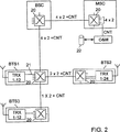
図2は、本発明のデータ伝送ネットワークの第1の好ましい実施例のブロック図である。例で、図2のデータ伝送ネットワークを、GSM(Global System for Mobile communications(移動通信のためのグローバルシステム))セルラー方式無線システムのデータ伝送ネットワークであると仮定する。GSMセルラー方式無線システムによって、データ伝送信号は、移動サービス交換センタMSCと、基地局コントローラBSCと、基地局BTS1からBTS3との間で伝送される。図2では、全てのネットワーク要素MSC、BSC、及び、BTS1からBTS3は、本発明のクロス接続要素20に統合され、それを介して、ネットワーク要素間の全データ伝送が運ばれる。図2は、ネットワーク要素につき1つのクロス接続要素のみを示しているけれども、例えば、もし、1つのクロス接続要素で達成することができる伝送容量よりも大きな伝送容量(2Mビット/sよりも大きいインターフェース)が、前記ネットワーク要素で必要とされるならば、単一ネットワーク要素に、複数のクロス接続要素を配置することは当然可能である。ネットワーク要素間のデータ伝送接続を、何らかの既知の方法で、例えば、同軸ケーブル、光ファイバーケーブル、無線リンク、もしくは、それらの組み合わせによって実行することができる。
図2は、移動サービス交換センタのクロス接続要素20が4つのインターフェースを有することを示し、それらの内の各々1つを介して、CCITT勧告G.704に従う2Mビット/sチャネルを両方向に伝送することができる。これに加えて、移動サービス交換センタMSCのクロス接続要素は、制御チャネルCNTの、システムのネットワーク管理センタO&Mへのインターフェースを有し、それは、クロス接続要素20を制御する。移動サービス交換センタMSCと基地局コントローラBSCとの間のシリアルデータ伝送接続によって、4つの2Mビット/sチャネルが両方向で伝送され、更に、例えば64kビット/sであり得る制御チャネルCNTも伝送される。伝送されるべきチャネルの数は、例で上述した4つから変わり得ることは、この接続において留意されるべきことである。例えば、16つの2Mビット/sチャネルを全く同様に移動サービス交換センタから更に基地局コントローラーへ伝送することができる。従って、前記16つのチャネル、上述した制御チャネル、おそらく必要とされる他のシグナリング及び/もしくは制御チャネルを、伝送フレームに挿入することができ、伝送フレームは、容量が例えば37Mビット/sであるシリアルデータ通信接続で伝送される。従って、図2のクロス接続要素20間の全シリアル接続が、この種の37Mビット/sの接続であっても良く、その容量の内の必要な部分のみが使用される。
制御チャネルCNTは、例えばポイント−トゥ−ポイントタイプの接続であっても良く、相互接続されたクロス接続要素20は、所望されるように、それを交互に使用する。代わりに、制御チャネルCNTは、ポイント−トゥ−マルチポイントタイプから成っても良く、従って、制御チャネルは、クロス接続要素において他のクロス接続要素へブランチされる。
例では、基地局コントローラBSCのクロス接続要素20は、移動サービス交換センタMSCから受信される2Mビット/sの信号を、基地局コントローラBSCを介して、基地局BTS1のクロス接続要素20へ、4×2Mビット/s+CNTを含むシリアルデータ信号として伝送するようにプログラムされる。図2では、基地局BTS1のクロス接続要素は、例えばトランシーバーTRX1から12といったようなそれ自体の装置へ、インターフェース21を介して、受信された2Mビット/sチャネルの内の1つを伝送するようにプログラムされ、それに加えて、クロス接続要素は、2×2Mビット/s+CNTを基地局BTS2へ伝送し、1×2Mビット/s+CNTを基地局BTS3へ伝送する。
基地局BTS3のクロス接続要素は、基地局BTS1以外の他のネットワーク要素と通信しない。従って、それは、受信されたチャネルを伝送せず、受信されたチャネルを全てそれ自体の装置の使用のために伝送する。同様に、基地局BTS2の装置は、前記基地局へ伝送された2つの2Mビット/Sチャネルを全て使用する。
クロス接続要素20はプログラム可能であるので、例えば、もし、基地局BTS2が過大なデータ伝送容量を有する一方で、基地局BTS3がより大きなデータ伝送容量を必要とすることが分かったならば、オペレータは、ネットワーク管理センタO&Mからネットワーク構成を変更することができる。すなわち、ネットワーク管理センタO&Mから、オペレータは、以降、基地局BTS1のクロス接続要素20が2つの2Mビット/sチャネルを基地局BTS3へ送り、そして、1つだけを基地局BTS2へ送ることを目的として、制御チャネルCNTを使用して、基地局BTS1のクロス接続要素20を再プログラムすることができる。同時に、クロス接続要素20の新しいルーティングデータをネットワーク管理センタO&Mのデータベース22に記憶することができ、ネットワーク管理センタで、ネットワーク構成をいつでも明確にすることができる。同様に、もし、基地局が、図2の移動電話システムに付加されるように所望されるならば、それを、前記新しい基地局のクロス接続要素が、基地局BTS2のクロス接続要素20のフリーシリアルポートの内のいずれか1つに接続されるといったように遂行でき、例えば、それ以降、オペレータは、以降、基地局BTS2のクロス接続要素が1つの2Mビット/sチャネルを新しい基地局へ伝送することを目的として、基地局BTS2のクロス接続要素をネットワーク管理センタO&Mから再プログラムすることができる。上述の説明から明らかなように、クロス接続要素のルーティングデータを、単一信号成分の精度で、すなわち例えば2Mビット/sチャネルの精度でプログラムすることができる。
図2の場合には、例えば、もし、データベース22が更新されないならば、オペレータはまた、制御要求をネットワーク管理センタO&Mからシステムのクロス接続要素20に伝送することができる。そして、制御要求を受信したクロス接続要素20は、制御チャネルCNTを使用して、メッセージをネットワーク管理センタに送り、そのメッセージから、クロス接続要素のメモリにその時点で記憶されているルーティングデータが分かる。とりわけ、これは、妨害の場合に障害の位置探しを容易にする。
図2の場合には、クロス接続要素を局所でプログラムすることができ、すなわち保守要員は、例えば携帯コンピュータもしくはそのようなものであるプログラミング端末を、クロス接続要素に接続することができ、従って、保守要員は、プログラミング端末を使用して、クロス接続要素のメモリに記憶されているルーティングデータを変更することができる。従って、プログラミングを終了した後、メッセージをネットワーク管理センタへ自動的に伝送するように、クロス接続要素をすることができ、そのメッセージから、前記クロス接続要素の新しいルーティングデータが分かる。
図3は、本発明のクロス接続要素の第1の好ましい実施例のブロック図である。
図3のクロス接続要素を、例えばASIC(Application Specific Integrated Circuite(特定用途向けIC))回路といった1つの単一回路に統合することができる。従って、その構造は非常に小型である。他の観点では、図3のクロス接続要素は、図2のクロス接続要素に相当するが、4つのインターフェースの代わりに、図3のクロス接続要素は、8つのインターフェース37を備える。
本発明によると、クロス接続要素は、少なくとも3つのシリアルポート31から33を備えており、それによって、これらのシリアルポートを使用して、クロス接続回路を相互接続することにより、ネットワークを分岐することは非常に簡単である。マルチプレクサ/デマルチプレクサ回路34から36は、各々のシリアルポートに関して配置され、その回路を使用して、受信方向で、シリアルデータ信号S1からS3の伝送フレームは分解されて、例えばCCITT勧告G.704に従う2Mビット/sチャネルといった単一信号成分を相互に分離することができる。同様に、伝送方向では、伝送されるべき信号成分は、シリアルデータ伝送接続の伝送フレームに挿入される。加えて、マルチプレクサ/デマルチプレクサ回路34から36はバッファを有する。信号S1からS3の充填ビットとともにバッファは、異なる接続のタイミング差異を補償する。
更に、クロス接続要素は複数のインターフェース37を備えており、それらのインターフェースを介して、いずれかの接続から受信されたシリアルデータ信号S1、S2もしくはS3の単一信号成分を、前記ネットワーク要素の使用のために伝送することができる。従って、例えば、1つの2Mビット/sチャネルを、インターフェース37の内の各々1つを介して、両方の伝送方向で伝送することができる。
クロス接続要素20は、更に、そのメモリ40に記憶されているルーティングデータに基づいて、制御ユニット39によって制御されるスイッチングフィールド38を備える。従って、単一信号成分は、シリアルポート31から33とインターフェース37との間のスイッチングフィールド38を介して、メモリ40に記憶されているルーティングデータに基づいて透過的に伝送される。
シリアルポート31から33を使用して、クロス接続要素20の制御ユニット39は、他の同様のクロス接続要素によって制御チャネルCNTで伝送されるデータを受信する。この種のデータには、例えば、図3のクロス接続要素20の新しいルーティングデータが含まれ、それによって、制御ユニット39は、前記新しいルーティングデータをメモリ40に記憶して、先のデータと置き換える。以降、制御ユニット39は、新しいルーティングデータに基づいて交換フィールド38を制御する。
上述した明細書及びそれに関する図面は、単に、本発明を例示することを意図されていることは理解されるべきである。すなわち、上記で、本発明を、例で、特にセルラー方式無線システムに関して説明したけれども、本発明を他のシステムに適用することも可能である。従って、添付の請求の範囲に開示された本発明の範囲及び精神から逸脱することなく、様々な方法で、本発明を変更して修正することができることは、当業者にとって明白である。The invention comprises at least one input, an output, and a blanching means for transmitting at least some signal components of a first serial data signal received via the input via a predetermined output. For cross-connect elements. The invention further relates to a data transmission network of a telecommunications system, which network comprises network elements that communicate with each other via a serial data transmission connection. The network element comprises at least one input, a branching means, and an output for transmitting at least some signal components of a serial data signal received via the network element input to other network elements. .
The present invention relates to telecommunications systems that use serial data transmission connections, and more particularly to the coupling of their network elements. For example, in a mobile telephone system, in general, a network element is only scheduled for use by the device of the network element itself, only a part of the data signal content transmitted from other parts of the system to a given network element. It is chained like The remainder of the data signal content transmitted to the network element is scheduled for use of the network element located further in the chain. In general, since one network element is coupled to multiple other network elements, it separates the data intended for it from the data to be transmitted for the received serial data signal. And in addition to that, the signal to be transmitted must be able to be transmitted over the correct data transmission connection.
In the known telecommunications system described above, the network element comprises demultiplexing means for separating the received serial data signal into a single signal component. Similarly, the output of a network element is provided with multiplexing means, whereby a single signal component supplied to the output is assembled into a serial signal to be transmitted to the next network element. In order to transmit the correct signal component further to the correct network element, the known network element comprises a switching matrix consisting of cables, and therefore using the cable to transmit the correct signal component from the input to the correct output. Can do. One known solution of this kind is illustrated in FIG.
A serious drawback with the solution described above is the complexity of the cabling and the inflexibility with respect to changes implemented in the network, i.e., for example, when network elements are added to the network. That is, changing the switching matrix requires an electrician to visit the installation site of the network element and change its cabling, ie physically change the cable end from one connector to another. is there. The number of cables is large and the risk of error is great because usually the cables need to be changed in multiple network elements. Finding the location of a committed error is difficult. This is because it is necessary to newly visit the installation site of the network element in order to clarify how the cables are coupled in the specific network element.
Further, a cross connection element according to PDH (plesiochronous digital hierarchy) is already known. However, in these known cross-connect elements, the signals they process have a nesting structure that follows the multiplexing hierarchy required by the standard, and as a result, because of the required PDH multiplexer stage, The connecting element has the disadvantage of being complicated and expensive. Another serious drawback is that according to the PDH hierarchy, only signals with
The object of the present invention is to provide a solution that solves the above-mentioned problems and considerably facilitates the management of the data transmission network. This is achieved with the cross-connect element of the present invention, where the branching means converts the single signal component of the serial data signal received via the input as a serial data signal to the memory means of the cross-connect element. Means for transparently transmitting via an output indicated by stored routing data, and wherein the cross-connect element is a first serial data signal indicated by the routing data stored in the memory means Characterized in that it comprises at least one output for transparent transmission of a single signal component.
The invention further relates to a data transmission network in which the cross-connect element of the invention can be used. The data transmission network of the present invention comprises at least one network element, the branching means including a cross connection element, which serially converts a single signal component of a serial data signal received via the input. Means for transparently transmitting as data signals to other network elements via outputs indicated by the routing data stored in the memory means of the cross-connect elements, and data signals received via said inputs And an output for transparent transmission of the single signal component to the device of the network element itself.
The present invention provides a cross-process that can transparently process, i.e. transmit, a single signal component of a received serial data signal based on routing data stored in a cross-connected memory via a correct output. By using the connection element, since the operation of the cross connection element is no longer dependent on the cable coupling as described above, but on the routing data stored in the memory means, Based on the idea that site cabling is much easier. This also greatly facilitates network reconfiguration. This is because for reconfiguration, it is sufficient to change the routing data stored in the memory means and there is no need to mess with on-site cabling. At best, routing data stored in the memory means can be changed even by remote control from the network management center, so that on-site visits of the electrician are not necessary for network reconfiguration. Become. The cross-connect element transparently transmits a single signal component of the received serial data signal, i.e. the cross-connect element transmits a single signal component without changing the information content or the structure of the signal component. The cross-connecting elements have a very simple structure and are inexpensive, and in addition, the cross-connecting elements are applicable to the transmission of various signals. By placing at least three serial ports on the cross-connect element, the cross-connect element is used to ensure that the branching point is provided to the telecommunications network in a very simple manner.
The use of the cross-connect element of the present invention does not require the use of any standard signal. However, the signals Si to be cross-connected (eg, S1, S2 and S3) should contain a sufficient number of mutually similar signals P1-n having equal bit rates, so that they are Can be cross-connected with cross-connect elements. Each signal Si may include a variable number of the signals Pj. The signals Pj are completely independent of each other, even though it is most advantageous to use standard data communication signals, for example 2M / E1 or 1.5M / T1, in the actual implementation. Do not have to match any particular standard.
The solution of the present invention does not require the use of a standard multiplexing hierarchy, and a variable number of similar 2M signals, for example, can be directly synthesized with the signal Si in the signal Si frame. Thus, the signal constitutes a signal n × 2M, where n can be between 1 and 16, for example. This substantially reduces the cost of implementation compared to standard signals (E2, E3,...) (Because it is not necessary to use the standard multiplexing hierarchy), thereby actually reducing the cost of cross-connect elements. Can be used, for example, to connect adjacent devices without disturbing.
Thus, the most important advantages of cross-connect elements and data transmission networks are the simple structure and price, the on-site cabling is considerably facilitated and the possible changes can be performed by remote control. As a result, maintenance personnel rarely need to visit the site, and the use of a database held in the network management center, for example, can reveal the connections of cross-connect elements, which can lead to errors Is reduced and it is easier to locate the error, so that the connection record no longer depends on the record that is manually recorded at the site (how the cabling of the cross-connect element is combined) And the number of cable connections required is considerably reduced, so that cross-connect elements The size is significantly reduced, and the cross-connect elements of the present invention also allow rerouting of a single signal component in the desired manner, thereby allowing all intermediate capacity to be used (eg, 1 to 16 × 2M), the use of cross-connect elements is very flexible.
Preferred embodiments of the cross-connect element and the data transmission network according to the invention are apparent from the attached
In the following, the invention will be described in more detail by way of example with reference to the accompanying drawings.
FIG. 1 illustrates a cross-connect unit of a prior art network element.
FIG. 2 is a block diagram of a first preferred embodiment of a data transmission network according to the present invention.
FIG. 3 is a block diagram of a first preferred embodiment of a cross-connect element according to the present invention.
FIG. 1 illustrates a
In FIG. 1, the
The signal from the output of the multiplexer / demultiplexer unit 5 is carried to the
Similar to
FIG. 1 shows that the operation of the
The fact that the operation of the
FIG. 2 is a block diagram of a first preferred embodiment of the data transmission network of the present invention. By way of example, assume that the data transmission network of FIG. 2 is a GSM (Global System for Mobile communications) cellular wireless system data transmission network. By means of the GSM cellular radio system, data transmission signals are transmitted between the mobile service switching center MSC, the base station controller BSC and the base stations BTS1 to BTS3. In FIG. 2, all network elements MSC, BSC and BTS1 to BTS3 are integrated into the
FIG. 2 shows that the mobile service switching center
The control channel CNT may be a point-to-point type connection, for example, and the interconnected
In the example, the
The cross connection element of the base station BTS3 does not communicate with other network elements other than the base station BTS1. Thus, it does not transmit the received channel, but transmits all received channels for use in its own device. Similarly, the base station BTS2 device uses all two 2Mbit / S channels transmitted to the base station.
Since the
In the case of FIG. 2, for example, if the
In the case of FIG. 2, the cross-connect element can be programmed locally, i.e. maintenance personnel can connect a programming terminal, for example a portable computer or the like, to the cross-connect element, thus Maintenance personnel can use the programming terminal to change the routing data stored in the memory of the cross-connect element. Thus, after programming is complete, the cross-connect element can be configured to automatically transmit a message to the network management center, from which the new routing data of the cross-connect element is known.
FIG. 3 is a block diagram of a first preferred embodiment of the cross-connect element of the present invention.
The cross-connect element of FIG. 3 can be integrated into one single circuit, for example an ASIC (Application Specific Integrated Circuite) circuit. Therefore, the structure is very small. In other respects, the cross-connecting element of FIG. 3 corresponds to the cross-connecting element of FIG. 2, but instead of four interfaces, the cross-connecting element of FIG.
According to the invention, the cross-connect element comprises at least three
Furthermore, the cross-connection element comprises a plurality of
The
Using the
It should be understood that the foregoing specification and the drawings related thereto are merely intended to illustrate the present invention. That is, although the present invention has been described above by way of example, particularly with respect to cellular radio systems, the present invention can also be applied to other systems. Thus, it will be apparent to one skilled in the art that the invention may be modified and modified in various ways without departing from the scope and spirit of the invention as disclosed in the appended claims.
Claims (9)
前記クロス接続要素は、シリアルデータ信号を受信し且つそれぞれが伝送を行う少なくとも3つのシリアルポート(31、32、33)を備え、
前記ブランチング手段は、前記シリアルポートの内の1つ(31)を介して受信されたシリアルデータ信号(S1)の単一信号成分を、シリアルデータ信号(S2、S3)として、クロス接続要素(20)のメモリ手段(40)に記憶されているルーティングデータによって示される前記シリアルポートの内の他の1つ(32、33)を介して透過的に伝送するための手段(38、39)を備え、
前記クロス接続要素(1)は、少なくとも1つのインタフェース(37)を備え、
該インタフェース(37)は、前記シリアルポート(31、32、33)の内のいずれか1つを介して受信され且つメモリ手段(40)に記憶されているルーティングデータによって示されるシリアルデータ信号の単一信号成分を透過的に伝送し、また、前記インタフェース(37)を介して単一信号成分をそれぞれ受信し且つ前記メモリ手段(40)に記憶されているルーティングデータによって示される前記シリアルポート(31、32、33)の内の1つを介して前記単一信号成分を透過的に伝送することを特徴とするクロス接続要素。 A serial port, respectively receiving the serial data signal and performs transmission (31, 32, 33), and (40 38) branching means, the cross connection element (20) comprising,
The cross-connect element comprises at least three serial ports (31, 32, 33) each receiving a serial data signal and transmitting each;
The branching means uses a single signal component of the serial data signal (S1) received via one (31) of the serial ports as a serial data signal (S2, S3) as a cross connection element ( Means (38, 39) for transparent transmission via the other one (32, 33) of said serial ports indicated by the routing data stored in memory means (40) of 20) Prepared,
Said cross-connecting element (1) comprises at least one interface (37);
The interface (37) is a single serial data signal indicated by routing data received via any one of the serial ports (31, 32, 33) and stored in the memory means (40). The serial port (31) transmits one signal component transparently and receives each single signal component via the interface (37) and indicated by routing data stored in the memory means (40). , 32, 33), wherein the single signal component is transmitted transparently via one of them .
メモリ手段(40)に応答して、デマルチプレクシング手段(34、35、36)の出力から受信された信号成分を、メモリ手段(40)に記憶されているルーティングデータによって示されるシリアルポート(31、32、33)若しくはインタフェース(37)に供給するためのスイッチング手段(38)と、
前記シリアルポート(31、32、33)に関して配置され、スイッチング手段(38)から受信された信号成分からシリアルデータ信号(S2、S3)を生成し、前記シリアルデータ信号(S2、S3)を、前記シリアルポート(31、32、33)を介して伝送するためのマルチプレクシング手段(35、36)とを備える請求項1に記載のクロス接続要素。Demultiplexing means (34 , 35, 36 ) for separating signal components of the received serial data signal (S1) from each other;
In response to the memory means (40), the signal component received from the output of the demultiplexing means (34 , 35, 36 ) is converted into a serial port (31) indicated by the routing data stored in the memory means (40). , 32, 33) or switching means (38) for supplying to the interface (37) ;
A serial data signal (S2, S3) is generated from a signal component arranged with respect to the serial port ( 31, 32 , 33) and received from the switching means (38), and the serial data signal (S2, S3) is Cross-connect element according to claim 1, comprising multiplexing means (35, 36) for transmission via a serial port ( 31, 32 , 33).
前記制御信号(CNT)に含まれるルーティングデータをメモリ手段(40)に記憶して、先のルーティングデータと置き換えるようにするための手段(39)とを備える請求項1に記載のクロス接続要素。Means (34) for separating a predetermined control signal (CNT) from the serial data signal (S1) received via the serial port (31);
The cross-connect element according to claim 1, comprising means (39) for storing the routing data contained in the control signal (CNT) in a memory means (40) to replace the previous routing data.
少なくとも1つのネットワーク要素(BTS1)を備えており、そのブランチング手段はクロス接続要素(20)に含まれ、該クロス接続要素は、
シリアルデータ信号を受信し且つそれぞれが伝送を行う少なくとも3つのシリアルポート(31、32、33)と、
前記シリアルポートの内の1つ(31)を介して受信されたシリアルデータ信号(S1)の単一信号成分を、シリアルデータ信号(S2、S3)として、クロス接続要素(20)のメモリ手段(40)に記憶されているルーティングデータによって示される前記シリアルポートの内の他の1つ(32、33)を介して、他のネットワーク要素(BSC、BTS2からBTS3)へ透過的に伝送するための手段(38、39)と、
少なくとも1つのインタフェース(21、37)と、を備え、
該インタフェース(21、37)は、前記メモリ手段(40)に記憶されているルーティングデータによって示され且つ前記シリアルポートの内の1つ(31)を介して受信されたシリアルデータ信号(S1)の単一信号成分を、ネットワーク要素(BTS1)自体の装置(TRX1から12)へ透過的に伝送し、また、前記メモリ手段(40)に記憶されているルーティングデータによって示される前記シリアルポート(31、32、33)の内の1つを介して、前記インタフェース(21、37)を介して受信された信号成分を透過的にそれぞれ伝送することを特徴とするデータ伝送ネットワーク。A data transmission network of a telecommunications system comprising network elements (MSC, BSC, BTS1 to BTS3) that communicate with each other over a serial data transmission connection, the network element comprising a serial port and In a data transmission network comprising branching means for transmitting at least some signal components of the received serial data signal to other network elements (MSC, BSC, BTS1 to BTS3),
Comprising at least one network element (BTS1), the branching means of which are included in the cross-connection element (20),
At least three serial ports (31, 32, 33) for receiving serial data signals and transmitting each;
The memory means (20) of the cross connection element (20) is obtained by using the single signal component of the serial data signal (S1) received via one (31) of the serial ports as the serial data signal (S2, S3). 40) for transparent transmission to other network elements (BSC, BTS2 to BTS3) via the other one of the serial ports (32, 33) indicated by the routing data stored in 40) Means ( 38, 39 );
At least one interface (21, 37),
The interface (21, 37) is indicated by the routing data stored in the memory means (40) and of the serial data signal (S1) received via one of the serial ports (31). A single signal component is transparently transmitted to the device (TRX1 to 12) of the network element (BTS1) itself, and the serial port (31, 31) indicated by the routing data stored in the memory means (40). 32. A data transmission network , wherein the signal components received via the interfaces (21, 37) are transmitted transparently via one of the channels 32, 33) .
前記少なくとも1つのネットワーク要素(BTS1)のクロス接続要素(20)は、受信されたシリアルデータ信号(S1)から制御信号(CNT)を分離し、また、制御信号に含まれる新しいルーティングデータをクロス接続要素(20)のメモリ手段(40)に記憶して、先のルーティングデータと置き換えるようにするための手段(34、39)を備える請求項6に記載のデータ伝送ネットワーク。The data transmission network comprises means for transmitting a control signal (CNT) including new routing data from a network management center (O & M) to a cross connection element (20) of the network element via the serial data transmission connection. And
The cross connection element (20) of the at least one network element (BTS1) separates the control signal (CNT) from the received serial data signal (S1) and cross connects the new routing data included in the control signal. A data transmission network according to claim 6, comprising means (34, 39) for storing in the memory means (40) of the element (20) to replace the previous routing data.
Applications Claiming Priority (3)
| Application Number | Priority Date | Filing Date | Title |
|---|---|---|---|
| FI972788A FI117736B (en) | 1997-06-27 | 1997-06-27 | Crossover element and communication network |
| FI972788 | 1997-06-27 | ||
| PCT/FI1998/000557 WO1999001008A2 (en) | 1997-06-27 | 1998-06-25 | Cross connection element and data transmission network |
Publications (2)
| Publication Number | Publication Date |
|---|---|
| JP2002507352A JP2002507352A (en) | 2002-03-05 |
| JP3818672B2 true JP3818672B2 (en) | 2006-09-06 |
Family
ID=8549150
Family Applications (1)
| Application Number | Title | Priority Date | Filing Date |
|---|---|---|---|
| JP50509399A Expired - Fee Related JP3818672B2 (en) | 1997-06-27 | 1998-06-25 | Cross-connect element and data transmission network |
Country Status (10)
| Country | Link |
|---|---|
| US (1) | US6144660A (en) |
| EP (1) | EP0986924B1 (en) |
| JP (1) | JP3818672B2 (en) |
| CN (1) | CN1185880C (en) |
| AT (1) | ATE344597T1 (en) |
| AU (1) | AU7921498A (en) |
| DE (1) | DE69836325T2 (en) |
| ES (1) | ES2274571T3 (en) |
| FI (1) | FI117736B (en) |
| WO (1) | WO1999001008A2 (en) |
Families Citing this family (4)
| Publication number | Priority date | Publication date | Assignee | Title |
|---|---|---|---|---|
| FI982321A0 (en) * | 1998-10-26 | 1998-10-26 | Nokia Telecommunications Oy | Transmission network |
| US6751217B1 (en) * | 1999-10-06 | 2004-06-15 | Nortel Networks Limited | Combined selector switch and serial multi-Gb/s data pulse receiver |
| GB0031839D0 (en) * | 2000-12-29 | 2001-02-14 | Marconi Comm Ltd | A multi-service digital cross-connect |
| GB0118158D0 (en) * | 2001-07-25 | 2001-09-19 | Marconi Comm Ltd | Telecommunications and data communications switching apparatus and method |
Family Cites Families (4)
| Publication number | Priority date | Publication date | Assignee | Title |
|---|---|---|---|---|
| FR2682246B1 (en) * | 1991-10-07 | 1993-12-31 | Matra Communication | COMMUNICATION METHOD AND INSTALLATION WITH TRANSMISSION OF DIGITAL SIGNALS. |
| FI96565C (en) * | 1992-06-30 | 1996-07-10 | Nokia Telecommunications Oy | Small Cell Radio Network |
| FI932373A0 (en) * | 1993-05-25 | 1993-05-25 | Nokia Telecommunications Oy | Basstation Foer cellular radio system as well as cellular radio system |
| FI102446B1 (en) * | 1996-12-05 | 1998-11-30 | Nokia Telecommunications Oy | Base station in a cellular network |
-
1997
- 1997-06-27 FI FI972788A patent/FI117736B/en active IP Right Grant
-
1998
- 1998-06-25 ES ES98929464T patent/ES2274571T3/en not_active Expired - Lifetime
- 1998-06-25 AU AU79214/98A patent/AU7921498A/en not_active Abandoned
- 1998-06-25 WO PCT/FI1998/000557 patent/WO1999001008A2/en active IP Right Grant
- 1998-06-25 JP JP50509399A patent/JP3818672B2/en not_active Expired - Fee Related
- 1998-06-25 DE DE69836325T patent/DE69836325T2/en not_active Expired - Fee Related
- 1998-06-25 EP EP98929464A patent/EP0986924B1/en not_active Expired - Lifetime
- 1998-06-25 CN CNB988066580A patent/CN1185880C/en not_active Expired - Fee Related
- 1998-06-25 AT AT98929464T patent/ATE344597T1/en not_active IP Right Cessation
-
1999
- 1999-12-22 US US09/470,171 patent/US6144660A/en not_active Expired - Lifetime
Also Published As
| Publication number | Publication date |
|---|---|
| AU7921498A (en) | 1999-01-19 |
| EP0986924B1 (en) | 2006-11-02 |
| JP2002507352A (en) | 2002-03-05 |
| WO1999001008A3 (en) | 1999-03-18 |
| ES2274571T3 (en) | 2007-05-16 |
| ATE344597T1 (en) | 2006-11-15 |
| FI972788A (en) | 1998-12-28 |
| WO1999001008A2 (en) | 1999-01-07 |
| DE69836325D1 (en) | 2006-12-14 |
| CN1262016A (en) | 2000-08-02 |
| DE69836325T2 (en) | 2007-02-15 |
| EP0986924A2 (en) | 2000-03-22 |
| FI972788A0 (en) | 1997-06-27 |
| US6144660A (en) | 2000-11-07 |
| FI117736B (en) | 2007-01-31 |
| CN1185880C (en) | 2005-01-19 |
Similar Documents
| Publication | Publication Date | Title |
|---|---|---|
| AU621011B2 (en) | Improved base station for mobile radio telecommunications systems | |
| US7154884B2 (en) | Stackplane architecture | |
| EP0503474B1 (en) | Routing system for linear add-drop multiplexer | |
| FI95854B (en) | Method and digital cross-connect architecture for cross-linking SDH signals | |
| JP3818672B2 (en) | Cross-connect element and data transmission network | |
| US6632032B1 (en) | Remote data network access in a communication network utilizing overhead channels | |
| CN105991455A (en) | Business exchange system and business exchange method | |
| GB2113953A (en) | Local loop communication network for routing date and telephone speech signals in digital form | |
| US9143252B2 (en) | Transmission apparatus and data communication channel processing method | |
| EP1368984B1 (en) | Communications network | |
| CN102246430A (en) | System and device for microwave communication, and method of connection for the system thereof | |
| EP1010297B1 (en) | Three-state output in a part of a cross-connecting device | |
| JP2001177866A (en) | Wireless communication system | |
| CN100534022C (en) | Method and device for connecting light cross linking channel and non-relative expense | |
| KR100304722B1 (en) | Data communication channel management device in optical subscriber transmission device | |
| EP0951796A1 (en) | Method and apparatus for communicating engineering orderwire information over synchronous communications network | |
| KR100601865B1 (en) | Construction of Link in Optical Transfer Network | |
| JP2621801B2 (en) | Wireless communication system | |
| WO1999011028A2 (en) | Method and apparatus for including control channels in a data stream | |
| JPH05327640A (en) | Subscriber connection system for subscriber transmitter | |
| CA2276605A1 (en) | Method and apparatus to interconnect two or more cross-connects into a single pcm network | |
| KR20020019181A (en) | Mobile telecommunication network cabling by optic cable | |
| JPH05327870A (en) | Transmitter management system | |
| KR20010055520A (en) | Communication method and apparatus between host system subscriber and remote system subscriber | |
| JPH1023571A (en) | Isdn terminal accommodation device for leased line |
Legal Events
| Date | Code | Title | Description |
|---|---|---|---|
| A977 | Report on retrieval |
Free format text: JAPANESE INTERMEDIATE CODE: A971007 Effective date: 20050914 |
|
| A131 | Notification of reasons for refusal |
Free format text: JAPANESE INTERMEDIATE CODE: A131 Effective date: 20051011 |
|
| A521 | Request for written amendment filed |
Free format text: JAPANESE INTERMEDIATE CODE: A523 Effective date: 20060111 |
|
| A711 | Notification of change in applicant |
Free format text: JAPANESE INTERMEDIATE CODE: A712 Effective date: 20060111 |
|
| TRDD | Decision of grant or rejection written | ||
| A01 | Written decision to grant a patent or to grant a registration (utility model) |
Free format text: JAPANESE INTERMEDIATE CODE: A01 Effective date: 20060606 |
|
| A61 | First payment of annual fees (during grant procedure) |
Free format text: JAPANESE INTERMEDIATE CODE: A61 Effective date: 20060613 |
|
| R150 | Certificate of patent or registration of utility model |
Free format text: JAPANESE INTERMEDIATE CODE: R150 |
|
| LAPS | Cancellation because of no payment of annual fees |