JP3818295B2 - Blood pressure measurement device - Google Patents
Blood pressure measurement device Download PDFInfo
- Publication number
- JP3818295B2 JP3818295B2 JP2004054362A JP2004054362A JP3818295B2 JP 3818295 B2 JP3818295 B2 JP 3818295B2 JP 2004054362 A JP2004054362 A JP 2004054362A JP 2004054362 A JP2004054362 A JP 2004054362A JP 3818295 B2 JP3818295 B2 JP 3818295B2
- Authority
- JP
- Japan
- Prior art keywords
- casing
- blood pressure
- living body
- pressure measurement
- measurement
- Prior art date
- Legal status (The legal status is an assumption and is not a legal conclusion. Google has not performed a legal analysis and makes no representation as to the accuracy of the status listed.)
- Expired - Lifetime
Links
- 238000009530 blood pressure measurement Methods 0.000 title claims description 34
- 238000005259 measurement Methods 0.000 claims description 112
- 230000007246 mechanism Effects 0.000 claims description 42
- 238000001514 detection method Methods 0.000 claims description 19
- 230000008878 coupling Effects 0.000 claims description 14
- 238000010168 coupling process Methods 0.000 claims description 14
- 238000005859 coupling reaction Methods 0.000 claims description 14
- 230000002093 peripheral effect Effects 0.000 claims description 6
- 238000003780 insertion Methods 0.000 description 121
- 230000037431 insertion Effects 0.000 description 121
- 230000036772 blood pressure Effects 0.000 description 50
- 238000004804 winding Methods 0.000 description 24
- 238000010586 diagram Methods 0.000 description 17
- 230000006835 compression Effects 0.000 description 14
- 238000007906 compression Methods 0.000 description 14
- 238000000034 method Methods 0.000 description 9
- 238000012360 testing method Methods 0.000 description 6
- 230000004872 arterial blood pressure Effects 0.000 description 5
- 239000012530 fluid Substances 0.000 description 5
- 210000001367 artery Anatomy 0.000 description 4
- 230000000694 effects Effects 0.000 description 4
- 230000004308 accommodation Effects 0.000 description 3
- 230000008569 process Effects 0.000 description 3
- 238000005452 bending Methods 0.000 description 2
- 210000000245 forearm Anatomy 0.000 description 2
- 230000002159 abnormal effect Effects 0.000 description 1
- 230000002411 adverse Effects 0.000 description 1
- 210000004712 air sac Anatomy 0.000 description 1
- 230000008901 benefit Effects 0.000 description 1
- 230000037237 body shape Effects 0.000 description 1
- 230000008602 contraction Effects 0.000 description 1
- 230000006866 deterioration Effects 0.000 description 1
- 230000035487 diastolic blood pressure Effects 0.000 description 1
- 239000007788 liquid Substances 0.000 description 1
- 210000003141 lower extremity Anatomy 0.000 description 1
- 238000012986 modification Methods 0.000 description 1
- 230000004048 modification Effects 0.000 description 1
- 210000003205 muscle Anatomy 0.000 description 1
- 230000035488 systolic blood pressure Effects 0.000 description 1
- 238000010977 unit operation Methods 0.000 description 1
- 210000001364 upper extremity Anatomy 0.000 description 1
- 210000000707 wrist Anatomy 0.000 description 1
Images


Classifications
-
- A—HUMAN NECESSITIES
- A61—MEDICAL OR VETERINARY SCIENCE; HYGIENE
- A61B—DIAGNOSIS; SURGERY; IDENTIFICATION
- A61B5/00—Measuring for diagnostic purposes; Identification of persons
- A61B5/02—Detecting, measuring or recording pulse, heart rate, blood pressure or blood flow; Combined pulse/heart-rate/blood pressure determination; Evaluating a cardiovascular condition not otherwise provided for, e.g. using combinations of techniques provided for in this group with electrocardiography or electroauscultation; Heart catheters for measuring blood pressure
- A61B5/021—Measuring pressure in heart or blood vessels
- A61B5/022—Measuring pressure in heart or blood vessels by applying pressure to close blood vessels, e.g. against the skin; Ophthalmodynamometers
- A61B5/02233—Occluders specially adapted therefor
Description
本発明は、血圧計測装置に関し、特に、カフを生体に対して自動的に巻き付けるカフ自動巻付機構を備えた血圧計測装置に関する。 The present invention relates to a blood pressure measurement device, and more particularly to a blood pressure measurement device including an automatic cuff winding mechanism that automatically winds a cuff around a living body.
通常、血圧値の測定は、生体内部に位置する動脈を圧迫するための生体圧迫用流体袋を備えたカフを生体の体表面に巻き付け、その後、生体圧迫用流体袋を膨張・収縮させることによって動脈内に生じる動脈圧脈波の検出を行い、これによって血圧値の測定を行なう。ここで、カフとは、内腔を有する帯状の構造物であって生体の一部に巻き付けが可能なものを意味し、気体や液体等の流体を内腔に注入することによって上下肢の動脈圧測定に利用されるもののことを指す。したがって、カフは、生体圧迫用流体袋とこの生体圧迫用流体袋を生体に巻き付けるための巻付手段とを含めた概念を示す言葉である。 Usually, blood pressure is measured by wrapping a cuff with a body compression fluid bag for compressing an artery located inside the living body around the body surface, and then expanding and contracting the body pressure fluid bag. The arterial pressure pulse wave generated in the artery is detected, and thereby the blood pressure value is measured. Here, the cuff means a band-like structure having a lumen, which can be wound around a part of a living body, and by injecting fluid such as gas or liquid into the lumen, the arteries of the upper and lower limbs It is used for pressure measurement. Therefore, the cuff is a term indicating a concept including a living body compressing fluid bag and a winding means for winding the living body compressing fluid bag around the living body.
従来の血圧計測装置(以下、単に血圧計とも称する)においては、生体へのカフの巻き付け作業を被験者等の手に委ねていたため、測定毎にカフの巻き付け強さにばらつきが生じ、結果として測定される血圧値にもばらつきが生じていた。このため、近年においては、自動的に生体へカフを巻き付けることが可能な自動カフ巻付機構を備えた血圧計が普及しつつある。この自動カフ巻付機構を搭載した血圧計においては、一定の巻き付け強さが測定毎に再現されるようになるため、安定した測定精度が実現されるばかりでなく、煩雑な巻き付け作業が不要になるというメリットも得られる。 In a conventional blood pressure measurement device (hereinafter also simply referred to as a sphygmomanometer), the cuff wrapping work around the living body is entrusted to the subject's hand, resulting in variations in the cuff wrapping strength for each measurement, resulting in measurement. There was also a variation in the blood pressure values. For this reason, in recent years, sphygmomanometers equipped with an automatic cuff winding mechanism capable of automatically winding a cuff around a living body are becoming widespread. In the sphygmomanometer equipped with this automatic cuff winding mechanism, a constant winding strength is reproduced for each measurement, so that not only stable measurement accuracy is realized, but also complicated winding work is unnecessary. The advantage of becoming
通常、自動カフ巻付機構を備えた血圧計においては、本体ケースの所定位置に生体を挿入するための中空開口部が設けられ、この中空開口部の内周面に生体を圧迫・固定するためのカフが配置される。そして、本体ケース内に収納された自動カフ巻付機構を用いて中空開口部内に挿入された上腕にカフを巻付け、血圧値の測定が行なわれる。 Usually, in a sphygmomanometer equipped with an automatic cuff winding mechanism, a hollow opening for inserting a living body is provided at a predetermined position of the main body case, and the living body is pressed and fixed on the inner peripheral surface of the hollow opening. Cuffs are placed. The cuff is wound around the upper arm inserted into the hollow opening using an automatic cuff winding mechanism housed in the main body case, and the blood pressure value is measured.
上述の自動カフ巻付機構を搭載した血圧計としては、たとえば、特開平10−314123号公報(特許文献1)に開示のものや、特開平10−314125号公報(特許文献2)に開示のもの、実開平2−135003号公報(特許文献3)に開示のものなどがある。これら文献に開示の血圧計においては、以下のような問題があった。 Examples of the blood pressure monitor equipped with the automatic cuff winding mechanism described above are disclosed in Japanese Patent Laid-Open No. 10-314123 (Patent Document 1) or disclosed in Japanese Patent Laid-Open No. 10-314125 (Patent Document 2). And those disclosed in Japanese Utility Model Laid-Open No. 2-135003 (Patent Document 3). The sphygmomanometers disclosed in these documents have the following problems.
まず、上述の特許文献1または2に開示の自動カフ巻付機構を備えた血圧計にあっては、腕を挿入するための中空開口部を含む生体挿入部が、カフの巻取り機構を内蔵する本体部と一体的に形成されているため、測定時において被験者の測定姿勢が制約されてしまうという問題があった。被験者の測定姿勢は、被験者の体型や、血圧計を設置する机の高さ、被験者が着席する椅子の高さ等の諸条件により様々に変化する。このため、生体挿入部の傾角と挿入した被験者の腕の傾角とが一致しない場合には、カフと腕との間に隙間が生じ、腕全体を均一に圧迫することができなくなる。このため、測定精度の悪化を招来していた。また、被験者にとっては、測定中において不自然な測定姿勢に拘束されることになるため、苦痛を伴うものとなってしまっていた。 First, in the sphygmomanometer including the automatic cuff winding mechanism disclosed in Patent Document 1 or 2 described above, the living body insertion portion including the hollow opening for inserting the arm incorporates the cuff winding mechanism. Since it is formed integrally with the main body portion to be measured, there is a problem that the measurement posture of the subject is restricted during measurement. The measurement posture of the subject varies depending on various conditions such as the body shape of the subject, the height of the desk on which the sphygmomanometer is installed, and the height of the chair on which the subject is seated. For this reason, when the inclination angle of the living body insertion portion does not coincide with the inclination angle of the inserted subject's arm, a gap is generated between the cuff and the arm, and the entire arm cannot be compressed uniformly. For this reason, the measurement accuracy is deteriorated. In addition, for the test subject, the measurement posture was constrained by the unnatural measurement posture during the measurement.
一方、上述の特許文献3に開示の自動カフ巻付機構を備えた血圧計にあっては、生体挿入部内に設けられたカフの巻付機構が板バネまたは複数のコイルバネによって支持されており、巻付機構自体は揺動するように構成されているが、生体挿入部自体に設けられた中空開口部は本体部と一体に設けられており、生体挿入部の挿入口で腕の挿入角度が制限されてしまい、測定時における被験者の測定姿勢が制約されてしまうという問題があった。したがって、上述の特許文献1および特許文献2に開示の自動カフ巻付機構に比べて、測定姿勢の自由度は多少向上するものの、十分に上記問題が解消されるまでには至っていない。また、巻付機構が板バネや複数のコイルバネによって弾性付勢された状態にあるため、これらバネが大きく撓んだ場合には、その弾性力による荷重がカフにかかり、測定精度の悪化を招来するという問題も有していた。 On the other hand, in the sphygmomanometer provided with the automatic cuff winding mechanism disclosed in Patent Document 3 described above, the cuff winding mechanism provided in the living body insertion portion is supported by a leaf spring or a plurality of coil springs, Although the winding mechanism itself is configured to swing, the hollow opening provided in the living body insertion portion itself is provided integrally with the main body portion, and the insertion angle of the arm is set at the insertion port of the living body insertion portion. There has been a problem that the measurement posture of the subject at the time of measurement is limited. Therefore, although the degree of freedom of the measurement posture is slightly improved as compared with the automatic cuff winding mechanism disclosed in Patent Document 1 and Patent Document 2 described above, the above problem has not been sufficiently solved. In addition, since the winding mechanism is elastically biased by a leaf spring or a plurality of coil springs, if these springs are greatly bent, the load due to the elastic force is applied to the cuff, leading to deterioration in measurement accuracy. It also had the problem of doing.
上記問題の解決を図った自動カフ巻付機構を備えた血圧計として、図27に示す如くの血圧計が知られている。図27に示す血圧計100Eにおいては、本体部110と生体挿入部140とを分離し、本体部110の後方端に設けた回転軸145によって本体部110と生体挿入部140とが回転自在に連結されている。これにより、非使用状態において本体部110上に位置する生体挿入部140が、被験者300の腕の挿入に伴って後方(図中矢印H方向)に倒れるようになり、測定姿勢に応じた角度に生体挿入部140の傾角が調節されるようになる。これにより、測定姿勢が制限されることによる苦痛を被験者に与えることなく、精度よく血圧値を測定することが可能になる。
しかしながら、上述の図27に示す血圧計においては、新たに以下のような問題が生じる。図27に示すように、血圧計100Eにおいては、上腕320にカフを装着させる際に、生体挿入部140が後方に向かって倒れる(図中矢印H方向)ため、生体挿入部140は本体部110に対して被験者300側とは反対の方向に向かって移動することになる。このため、被験者300はこの生体挿入部140の動きに合わせて前傾姿勢をとる必要が生じる。したがって、図27に示すように、被験者300が上腕320をカフに装着させるためには、机210側に向かって前屈みの姿勢をとる必要が生じ、この状態を数十秒程度の測定の間維持することが要求される。このため、測定が終了するまでの間、被験者300に苦痛を与えることになってしまう。
However, in the sphygmomanometer shown in FIG. 27 described above, the following new problems arise. As shown in FIG. 27, in the sphygmomanometer 100E, when the cuff is attached to the
この図27に示す血圧計100Eにおいて、測定が前屈みとならない背筋が伸びた状態で測定するためには、血圧計100E自体を机210の前方端にまで移動させるか、あるいは椅子220を引いて身体を机側に寄せることが必要になる。しかしながら、上腕320を挿し込んだ状態での調整は非常に煩雑なものとなり、被験者300に負担をかけることになってしまう。
In the sphygmomanometer 100E shown in FIG. 27, in order to measure in a state where the back does not bend forward, the sphygmomanometer 100E itself is moved to the front end of the
そこで、本発明は、上述の問題点を解決すべくなされたものであり、高い精度で血圧値を測定することが可能であり、測定中において被験者に苦痛を与えることなく、無理なく自然な姿勢にて測定を行なうことが可能となる自動カフ巻付機構を備えた血圧計測装置を提供することを目的とする。 Therefore, the present invention has been made to solve the above-mentioned problems, and can measure blood pressure values with high accuracy, and does not give pain to the subject during measurement, and it is a natural posture without difficulty. An object of the present invention is to provide a blood pressure measurement device provided with an automatic cuff winding mechanism that can perform measurement at the same time.
本発明に基づく血圧計測装置は、載置面に載置される第1の筐体と、非使用状態において上記第1の筐体上に位置し、被験者の上腕が軸方向から挿入される中空開口部を有するカフが内周面上に配置された略円筒状の第2の筐体と、上記第1の筐体が上記載置面に載置された状態で、上記第2の筐体が、被験者に対する上記カフの装着に際して非使用状態における位置よりも被験者側に移動可能となるように、上記第2の筐体を上記第1の筐体に対して移動自在に連結する連結手段とを備える。 A blood pressure measurement device according to the present invention includes a first housing placed on a placement surface and a hollow in which an upper arm of a subject is inserted from an axial direction, positioned on the first housing in a non-use state. A substantially cylindrical second casing in which a cuff having an opening is disposed on the inner peripheral surface, and the second casing in a state where the first casing is placed on the mounting surface. Connecting means for movably connecting the second housing to the first housing so that the cuff can be moved to the subject side rather than a position in the non-use state when the cuff is attached to the subject. Is provided.
上記本発明に基づく血圧計測装置にあっては、上記第2の筐体の傾斜レベルを検知する傾斜レベル検知手段をさらに備えていることが好ましい。 The blood pressure measurement device according to the present invention preferably further includes an inclination level detecting means for detecting the inclination level of the second casing.
上記本発明に基づく血圧計測装置にあっては、上記傾斜レベル検知手段によって検知された上記第2の筐体の傾斜レベルが予め定められた所定の範囲内にあるか否かを判定し、その判定結果を被験者に対して報知する報知手段をさらに備えていることが好ましい。 In the blood pressure measurement device according to the present invention, it is determined whether or not the inclination level of the second casing detected by the inclination level detection means is within a predetermined range, It is preferable that a notification unit that notifies the subject of the determination result is further provided.
上記本発明に基づく血圧計測装置にあっては、上記傾斜レベル検知手段によって検知された上記第2の筐体の傾斜レベルが予め定められた所定の範囲内にあるか否かを判定し、上記所定の範囲内になかった場合には、測定動作中においては測定動作を中断し、測定動作前においては測定動作に移行しないように制御する制御手段をさらに備えていることが好ましい。 In the blood pressure measurement device according to the present invention, it is determined whether or not the inclination level of the second casing detected by the inclination level detection means is within a predetermined range, In the case where it is not within the predetermined range, it is preferable to further include control means for controlling the measurement operation to be interrupted during the measurement operation and not to shift to the measurement operation before the measurement operation.
上記本発明に基づく血圧計測装置にあっては、上記傾斜レベル検知手段が、上記第2の筐体の水平面に対する傾角を検知する手段であることが好ましい。 In the blood pressure measurement device according to the present invention, it is preferable that the inclination level detection means is means for detecting an inclination angle of the second casing with respect to a horizontal plane.
上記本発明に基づく血圧計測装置にあっては、上記傾斜レベル検知手段が、上記第2の筐体の第1の筐体に対する傾角を検知する手段であることが好ましい。 In the blood pressure measurement device according to the present invention, it is preferable that the inclination level detection means is means for detecting an inclination angle of the second casing with respect to the first casing.
上記本発明に基づく血圧計測装置にあっては、上記傾斜レベル検知手段が、上記第1の筐体に対する上記第2の筐体の移動量を検知する手段であることが好ましい。 In the blood pressure measurement device according to the present invention, it is preferable that the inclination level detection means is a means for detecting a movement amount of the second casing relative to the first casing.
上記本発明に基づく血圧計測装置にあっては、上記連結手段が、上記第1の筐体に対して上記第2の筐体を回転自在に軸支する回転軸を含む回転連結機構からなることが好ましい。 In the blood pressure measurement device according to the present invention, the connection means includes a rotation connection mechanism including a rotation shaft that rotatably supports the second case with respect to the first case. Is preferred.
上記本発明に基づく血圧計測装置にあっては、上記回転軸が、上記第1の筐体の被験者側の端部に設けられていることが好ましい。 In the blood pressure measurement device according to the present invention, it is preferable that the rotation shaft is provided at the end of the first housing on the subject side.
上記本発明に基づく血圧計測装置にあっては、上記第2の筐体を移動させるために上記回転軸に加える必要のある回転トルクが、測定時における上記カフの圧力変動に伴って上記回転軸に生じる回転トルクよりも小さいことが好ましい。 In the blood pressure measurement device according to the present invention, the rotational torque that needs to be applied to the rotation shaft in order to move the second casing is caused by the pressure fluctuation of the cuff at the time of measurement. Is preferably smaller than the rotational torque generated in
上記本発明に基づく血圧計測装置にあっては、上記回転連結機構が、上記第2の筐体の急激な回転移動を抑制するダンパーまたは摩擦バネを備えていることが好ましい。 In the blood pressure measurement device according to the present invention, it is preferable that the rotary coupling mechanism includes a damper or a friction spring that suppresses a rapid rotational movement of the second casing.
上記本発明に基づく血圧計測装置にあっては、上記回転連結機構が、上記第2の筐体を上記第1の筐体から遠ざける方向に付勢する付勢手段と、非使用状態において上記付勢手段による付勢に抗して上記第2の筐体を上記第1の筐体に固定する固定手段とをさらに備えていることが好ましい。 In the blood pressure measurement device according to the present invention, the rotation coupling mechanism biases the second casing in a direction away from the first casing, and the biasing mechanism when not in use. It is preferable to further include a fixing unit that fixes the second casing to the first casing against the biasing by the biasing unit.
上記本発明に基づく血圧計測装置にあっては、上記連結手段が上記第1の筐体に対して上記第2の筐体をスライド移動自在に支持するスライド連結機構から構成されていてもよい。 In the blood pressure measurement device according to the present invention, the connecting means may be constituted by a slide connecting mechanism that slidably supports the second housing with respect to the first housing.
本発明によれば、測定中において被験者に苦痛を与えることなく、無理なく自然な姿勢にて血圧測定を行なえるようになり、精度よく安定的に血圧値を測定することが可能になる。 According to the present invention, blood pressure can be measured in a natural posture without causing pain to the subject during measurement, and the blood pressure value can be measured accurately and stably.
以下、本発明の実施の形態について、図を参照して詳細に説明する。 Hereinafter, embodiments of the present invention will be described in detail with reference to the drawings.
(実施の形態1)
本実施の形態における血圧計は、被験者の上腕を圧迫することにより動脈圧脈波を検出し、血圧値を測定するものである。本実施の形態における血圧計は、自動カフ巻付機構を備えており、この自動カフ巻付機構によって上腕へのカフの巻付けが行なわれる。
(Embodiment 1)
The sphygmomanometer in the present embodiment detects an arterial pressure pulse wave by pressing the upper arm of a subject and measures a blood pressure value. The sphygmomanometer in the present embodiment includes an automatic cuff winding mechanism, and the cuff is wound around the upper arm by the automatic cuff winding mechanism.
図1および図2は、本発明の実施の形態1における血圧計の外観構造を説明するための図であり、図1は本実施の形態における血圧計を右斜め上方から見た場合の斜視図であり、図2は、左斜め上方から見た場合の斜視図である。 1 and 2 are views for explaining the external structure of a sphygmomanometer according to Embodiment 1 of the present invention, and FIG. 1 is a perspective view when the sphygmomanometer according to the present embodiment is viewed obliquely from the upper right. FIG. 2 is a perspective view when viewed obliquely from the upper left.
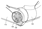
図1および図2に示すように、本実施の形態における血圧計100Aは、机等の載置面に載置される本体部110と、被験者の生体の一部(本実施の形態における血圧計100Aにおいては上腕)が挿入される中空開口部150を有する生体挿入部140とを主に備えている。本体部110は、第1の筐体である本体部ケーシング112によって覆われており、生体挿入部140は、第2の筐体である生体挿入部ケーシング142によって覆われている。
As shown in FIGS. 1 and 2, a
本体部110の上面には、電源の投入に用いられる電源ボタンや測定動作を開始させるための測定ボタン、表示部の操作を行なう表示部操作ボタンなどの種々のボタンが配置された操作部114が設けられている。また、本体部110の上面の他の位置には、測定結果や操作ガイド等を表示するための表示部116が設けられている。操作部114および表示部116に隣接する本体部110の上面の所定位置には、被験者が測定姿勢をとった際に肘を載置するための肘置き119が設けられている(図9参照)。この肘置き119は、たとえば本体部ケーシング112の上面に凹部を設けることによって構成される。
On the upper surface of the
生体挿入部140は、回転軸を含む回転連結機構によって本体部110に対して回転自在に連結されている。具体的には、本体部110の被験者側に位置する前方端寄りの本体部ケーシング112内に配置された回転軸によって、本体部ケーシング112と生体挿入部ケーシング142とが回転自在に連結されている。
The living
生体挿入部140は、略円筒状の生体挿入部ケーシング142の内周面上に配置されたカフと、カフを覆うように生体挿入部ケーシング142に取付けられたカフカバー148とを備える。また、生体挿入部ケーシング142の外周面の所定位置には、被験者が生体挿入部140を回転移動させるために把持する把手144が設けられている。また、この把手144の近傍には、本体部110上に収納された生体挿入部ケーシング142を回転移動させるために使用する開錠ボタン146が設けられている。この開錠ボタン146およびこれに連動する開錠/固定機構については、後述することとする。
The living
図3は、図1および図2に示す血圧計の機能ブロックを示す図である。図3に示すように、上述のカフに含まれる生体圧迫用空気袋152は、生体圧迫用エア系120にエアチューブ154によって接続されている。また、生体圧迫用エア系120は、CPU128によってその動作が制御される。
FIG. 3 is a diagram showing functional blocks of the sphygmomanometer shown in FIGS. 1 and 2. As shown in FIG. 3, the living body
生体圧迫用エア系120は、エアポンプ121と、エアバルブ122と、圧力センサ123とを含んでいる。エアポンプ121は、生体圧迫用空気袋152の内腔を加圧するための手段であり、CPU128からの指令を受けたエアポンプ駆動回路124によって駆動され、測定時において生体圧迫用空気袋152の内腔の圧力が所定の圧力となるように圧縮気体を内腔に送り込む。エアバルブ122は、生体圧迫用空気袋152の内腔の圧力を維持したり、あるいは減圧したりするための手段であり、CPU128からの指令を受けたエアバルブ駆動回路125によってその開閉状態が制御され、測定時においてエアポンプ121によって高圧状態となった生体圧迫用空気袋152の内腔の圧力の維持および減圧を行なうとともに、測定終了後において生体圧迫用空気袋152の内腔を大気圧に復帰させる。圧力センサ123は、生体圧迫用空気袋152の内腔の圧力を検出するための手段であり、測定時において時々刻々と変化する生体圧迫用空気袋152の内腔の圧力を検出し、その検出値に応じた信号を増幅器126に対して出力する。増幅器126は、圧力センサ123から出力される信号を増幅し、A/Dコンバータ127に出力する。A/Dコンバータ127は、増幅器126から出力されたアナログ信号をデジタル化し、CPU128に出力する。
The living body
CPU128は、血圧計の本体部110に設けられた操作部114に入力された指令に基づいて生体圧迫用エア系120の制御を行なうとともに、測定結果を表示部116やメモリ部129に出力する。なお、メモリ部129は、測定結果を記憶するための手段である。
The
本実施の形態における血圧計100Aにおいては、図3に示す各機能ブロックのうち、生体圧迫用空気袋152および圧力センサ123を除くすべての機能ブロックが本体部110に設けられており、本体部ケーシング112内に収容されている。生体圧迫用空気袋152および圧力センサ123は、生体挿入部140に設けられており、生体挿入部ケーシング142内に収容されている。生体圧迫用空気袋152とエアポンプ121およびエアバルブ122とは、フレキシブルなエアチューブによって接続されており、圧力センサ123と増幅器126は、フレキシブルな信号線によって接続されている。このようにフレキシブルなエアチューブおよび信号線を用いて本体部ケーシング内に収容された構成品と生体挿入部ケーシング142内に収容された構成品とを接続することにより、生体挿入部ケーシング142の回転移動に追従しつつ、エアの注入および排出あるいは信号の送受信が行なえるようになる。
In
図4および図5は、本実施の形態における血圧計を右側方から見た場合の側面図である。このうち、図4は、本体部ケーシング上に生体挿入部ケーシングが位置している収納状態を示す図であり、図5は、生体挿入部ケーシングを可能な限り被験者側に向かって回転移動させた最大可動状態を示す図である。 4 and 5 are side views when the blood pressure monitor in the present embodiment is viewed from the right side. Among these, FIG. 4 is a figure which shows the accommodation state where the biological insertion part casing is located on the main-body part casing, and FIG. 5 rotated the biological insertion part casing toward the test subject side as much as possible. It is a figure which shows a maximum movable state.
上述のように、本実施の形態における血圧計100Aにおいては、本体部ケーシング112と生体挿入部ケーシング142とが分離され、分離された本体部ケーシング112と生体挿入部ケーシング142とが回転軸を含む回転連結機構によって連結された構成を有している。
As described above, in blood pressure monitor 100A according to the present embodiment,
図4に示すように、収納状態(非使用状態)における血圧計100Aにあっては、本体部ケーシング112上に生体挿入部ケーシング142が位置している。本体部ケーシング112の上面は、机等の水平な載置面上に血圧計100Aの本体部ケーシング112を載置した場合に水平面から所定の角度をもって傾斜して位置するように予め傾斜させて形成されている。生体挿入部ケーシング142は、この傾斜した上面にその中空開口部150の軸線が直交する状態で本体部ケーシング112上に収納されている。なお、この収納状態における生体挿入部ケーシング142の水平面に対する傾角をR1とする。
As shown in FIG. 4, in the
図5に示すように、生体挿入部ケーシング142が被験者によって回転移動され、その回転移動が制限される範囲である回転可動範囲内で最も被験者側に回転させた最大可動状態に位置した場合においては、生体挿入部ケーシング142が本体部ケーシング112よりも被験者側に移動した状態となる。この状態において、中空開口部150の軸線は、水平面と平行な状態を僅かに超える程度にまで倒れた状態となる。なお、この最大可動状態における生体挿入部ケーシング142の水平面に対する傾角をR2とする。
As shown in FIG. 5, when the living body
本実施の形態における血圧計100Aにおいては、生体挿入部ケーシング142が、被験者の操作によって図4に示す収納状態における位置と図5に示す最大可動状態における位置との間の可動範囲内で自在に回転移動する。すなわち、生体挿入部ケーシング142が、収納状態における位置から角度(R1+R2)の範囲内で被験者側に向かって回転移動する。
In
本実施の形態における血圧計100Aにおいては、生体挿入部ケーシング142を回転移動させるために回転軸に加える必要のある回転トルクが、測定時におけるカフの圧力変動に伴って回転軸に生じる回転トルクよりも小さいことが好ましい。ここで言う、測定時におけるカフの圧力変動に伴って回転軸に生じる回転トルクとは、測定時において、カフが膨張または収縮することによって生体挿入部ケーシング142が押され、これに伴って生体挿入部ケーシング142によって回転軸に加えられる回転トルクのことである。このように回転軸の回転トルク調整を行なうことにより、測定時におけるカフの圧力変動に伴う生体挿入部ケーシング142の移動が制限されることがなくなるため、生体に対するカフの密着性が向上し、高精度の血圧測定が行なえるようになる。
In
また、本実施の形態における血圧計100Aにおいては、回転連結機構がダンパーまたは摩擦バネを備えていてもよい。ダンパーまたは摩擦バネは、生体挿入部ケーシング142の急激な回転移動を抑制するために設けられるものであり、回転軸と生体挿入部ケーシング142または/および本体部ケーシング112との連結部分に設けられる。このように構成することにより、測定時において、たとえば被験者が姿勢を変更した場合などの急激な生体挿入部ケーシング142の回転移動が抑制されるため、異常な圧脈波検出によるアーチファクトエラーの発生を防止することが可能になる。また、カフを生体に装着する装着時においては、生体挿入部ケーシング142を所望の角度に調整する作業の操作性の向上も図られるようになる。
Further, in blood pressure monitor 100A in the present embodiment, the rotary coupling mechanism may include a damper or a friction spring. The damper or the friction spring is provided to suppress a rapid rotational movement of the living body inserting
図6は、本実施の形態における血圧計の図2に示す領域VIを拡大した図であり、上述の回転連結機構に含まれる付勢手段としてのコイルバネの形状を説明するために本体部ケーシングの一部を取り除いた状態を示すものである。 FIG. 6 is an enlarged view of the region VI shown in FIG. 2 of the sphygmomanometer according to the present embodiment. In order to explain the shape of the coil spring as the urging means included in the above-described rotary coupling mechanism, FIG. It shows the state where a part has been removed.
回転連結機構は、回転軸の他に、収納状態において生体挿入部ケーシング142を本体部ケーシング112から遠ざける方向に付勢する付勢手段としてのコイルバネ130を備えている。コイルバネ130は、その一端が本体部ケーシング112に固定されており、他端132が生体挿入部ケーシング142に固定されている。
In addition to the rotating shaft, the rotation coupling mechanism includes a
図7は、本実施の形態における血圧計の開錠/固定機構を説明するための一部破断側面図である。図8は、図7に示す領域VIIIの拡大図であり、生体挿入部が回転移動可能となるように本体部に対する生体挿入部の固定を解除する場合の開錠動作を示す図である。また、図9は、図8に示す開錠動作によって開錠された状態を示す斜視図である。 FIG. 7 is a partially broken side view for explaining the unlocking / fixing mechanism of the sphygmomanometer according to the present embodiment. FIG. 8 is an enlarged view of the region VIII shown in FIG. 7, and is a diagram showing an unlocking operation in a case where the fixation of the living body insertion portion with respect to the main body portion is released so that the living body insertion portion can be rotationally moved. FIG. 9 is a perspective view showing a state where the door is unlocked by the unlocking operation shown in FIG.
図7に示すように、非使用状態において生体挿入部ケーシング142は本体部ケーシング112上に位置しており、本体部ケーシング112に固定されている。すなわち、非使用状態において、生体挿入部ケーシング142は、上述の付勢手段としてのコイルバネ130による弾性付勢力に抗して固定手段によって本体部ケーシング112に固定されている。固定手段は、後述する本体部ケーシング112内に設けられたフック117と生体挿入部ケーシング142に設けられた鈎状部143によって構成される。
As shown in FIG. 7, the living body
図7および図8(a)に示すように、生体挿入部ケーシング142の内部には、開錠ボタン146に連動する開錠レバー147が挿通されている。開錠レバー147の先端147aは本体部ケーシング112にまで達しており、本体部ケーシング112に設けられたフック117に当接している。フック117の先端117aは、生体挿入部ケーシング142に設けられた鈎状部143に掛合しており、フック117は、コイルバネ118によってこの掛合が外れない方向に弾性付勢されている。
As shown in FIG. 7 and FIG. 8A, an unlocking
図8(b)に示すように、開錠ボタン146が押下されることにより、開錠レバー147が図中矢印B方向に向かって移動し、開錠レバー147の先端147aがフック117の上端に設けられたテーパ面を押し下げ、これによりフック117がコイルバネ118の付勢力に抗して図中矢印C方向に回転する。このフック117の回転により、図8(c)に示すように、フック117の先端117aと生体挿入部ケーシング142の鈎状部143との掛合が解除され、本体部ケーシング112に対する生体挿入部ケーシング142の固定が解除される。これにより、本体部ケーシング112に対する生体挿入部ケーシング142の回転移動が可能になる。
As shown in FIG. 8B, when the unlocking
上記掛合が解除された状態においては、上述した図6に示すコイルバネ130による付勢力によって生体挿入部ケーシング142が、図9に示す位置にまで押し上げられる。すなわち、生体挿入部ケーシング142が回転軸を基点に被験者側に向かって回転移動し、本体部ケーシング112よりも被験者側に移動し、生体挿入部ケーシング142の自重とコイルバネ130の弾性付勢力とが釣り合った位置で生体挿入部ケーシング142が停止する。なお、この開錠動作に伴って移動する生体挿入部ケーシング142の停止位置は、コイルバネ130の弾性付勢力と生体挿入部ケーシング142の自重とを適宜変更することにより、所望の角度に設定することが可能である。
In the state where the engagement is released, the living body inserting
図10は、本実施の形態における血圧計におけるカフの装着手順を示す模式図であり、生体挿入部の中空開口部に腕を挿し込む様子を示す図である。また、図11は、装着後の測定姿勢を示す模式図である。なお、これらの図においては、右腕で血圧値を測定する場合を想定している。 FIG. 10 is a schematic diagram showing a cuff attachment procedure in the sphygmomanometer according to the present embodiment, and shows how the arm is inserted into the hollow opening of the living body insertion portion. FIG. 11 is a schematic diagram showing a measurement posture after mounting. In these figures, it is assumed that the blood pressure value is measured with the right arm.
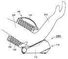
図10に示すように、本実施の形態における血圧計100Aを用いて血圧値を測定する場合には、水平な載置面を有する机210上に血圧計100Aの本体部110を載置し、被験者300は椅子220に着席する。そして、開錠ボタン146を押下して生体挿入部140を図中矢印A1方向に移動させ、さらに左手で血圧計100Aの生体挿入部ケーシング142に設けられた把手144を把持して生体挿入部140の傾角を調整しつつ、右手を生体挿入部140の中空開口部150に挿し込む。右手を中空開口部150内の奥に向かってさらに挿し込むことにより、前腕310を経由して生体挿入部140内に設けられたカフが上腕320に面する位置にくるまで右腕を挿し込む。そして、中空開口部150に挿し込んだ右腕の肘を軽く曲げ、肘を本体部110の上面に設けられた肘置き119に載せることにより、図11に示す如くの測定姿勢となる。
As shown in FIG. 10, when measuring a blood pressure value using the
この一連の装着動作においては、右腕の傾角に合わせて生体挿入部140の傾角が変動する。つまり、中空開口部150に挿し込んだ右手や右腕が生体挿入部140の中空開口部150の内周面に接触することにより、右手の動きに追従して生体挿入部140が回転する。たとえば、右手を挿しこむ段階においては、図10に示す如くの最大可動状態もしくはそれに近い位置にまで生体挿入部140を回転させておくことが被験者への負担が少なく好ましいが、その後、右手および右腕をさらに挿し込む段階においては、図11に示すように、右手および右腕の動きに追従して生体挿入部140が図中矢印A2方向に回転移動することが好ましい。本実施の形態における血圧計100Aにおいては、生体挿入部140を回転させるために回転軸に加える必要のある回転トルクを調整することにより、右手および右腕の動きに対する生体挿入部140の追従を実現している。
In this series of mounting operations, the tilt angle of the living
図10における測定姿勢においては、被験者300の背筋は伸びた状態になり、従来問題となっていた前屈みの測定姿勢となることはない。このため、心臓330の高さと測定部位である上腕320の高さがほぼ同じ高さに維持されるようになり、精度よく血圧値を測定することが可能になる。これは一意に、本体部110に対して生体挿入部140が前方に向かって回転移動するためであり、本実施の形態の如くの構成の血圧計100Aとすることにより、生体挿入部140に上腕320を挿し込んだ後に椅子220を引き直したり、血圧計100Aを手前に引き寄せたりすることによって測定姿勢を正す必要がなくなるため、非常に使い勝手のよい血圧計とすることが可能になる。
In the measurement posture in FIG. 10, the back muscle of the subject 300 is in an extended state, and does not become the measurement posture of the forward bending which has been a problem in the past. For this reason, the height of the
図12は、本実施の形態における血圧計を用いて血圧値を測定する際の測定姿勢を示す模式断面図である。図12に示すように、本実施の形態における血圧計100Aにおいては、生体圧迫用空気袋152を膨張・収縮させることにより、上腕320内に位置する動脈内に生じる動脈圧脈波の検出が行われ、これによって血圧値の測定が行なわれる。なお、この測定中においても、上腕の動きに対して生体挿入部140が追従して回転するため、生体に対するカフの密着性が向上し、高精度の測定が可能となる。
FIG. 12 is a schematic cross-sectional view showing a measurement posture when measuring a blood pressure value using the sphygmomanometer in the present embodiment. As shown in FIG. 12, in
以上において説明した本実施の形態の如くの血圧計の構成を採用することにより、測定中において被験者に苦痛を与えることがなくなるとともに、どのような条件下においても無理なく自然な姿勢にて測定を行なうことができるようになる。このため、結果として、精度よく安定的に血圧値を測定することが可能になる。 By adopting the configuration of the sphygmomanometer as in the present embodiment described above, the subject is not painful during the measurement, and the measurement is performed with a natural posture without any difficulty under any conditions. You can do it. For this reason, as a result, it becomes possible to measure a blood pressure value accurately and stably.
(実施の形態2)
本実施の形態における血圧計は、上述の実施の形態1における血圧計と同様に、被験者の上腕を圧迫することにより動脈圧脈波を検出し、血圧値を測定するものであり、上腕へのカフの巻付けが自動カフ巻付機構によって自動的に行なわれるものである。このため、上述の実施の形態1における血圧計と同様の部分について図中同一の符号を付し、その説明はここでは繰り返さない。
(Embodiment 2)
The sphygmomanometer in the present embodiment, like the sphygmomanometer in the first embodiment described above, detects the arterial pressure pulse wave by pressing the upper arm of the subject and measures the blood pressure value. The cuff winding is automatically performed by an automatic cuff winding mechanism. For this reason, the same code | symbol is attached | subjected in the figure about the part similar to the blood pressure meter in the above-mentioned Embodiment 1, and the description is not repeated here.
本実施の形態における血圧計においては、上述の実施の形態1における血圧計と同様に、生体挿入部ケーシングと本体部ケーシングとが回転軸を含む回転連結機構によって連結されており、生体挿入部ケーシングが本体部ケーシングに対して回転自在に移動する。その可動範囲は、上述の実施の形態1における血圧計と同様に、被験者がカフを装着する装着動作時において腕を挿し込むことが容易に行なえるように、大きく確保されている。 In the sphygmomanometer according to the present embodiment, the living body insertion portion casing and the main body casing are connected by a rotation coupling mechanism including a rotation shaft, similarly to the sphygmomanometer according to the first embodiment described above. Moves freely with respect to the main body casing. Similar to the sphygmomanometer in the first embodiment described above, the movable range is ensured so that the subject can easily insert the arm during the wearing operation of wearing the cuff.
しかしながら、このように血圧計を構成した場合には、血圧測定に適していない測定姿勢を被験者がとっている場合にも血圧値の測定が行なえてしまうという問題が生じる。生体挿入部ケーシングの可動範囲を広くとればとるほどその危険性は増し、カフを装着した上腕の高さと心臓の高さとが大きくずれることによって測定精度が低下することが懸念されるようになる。そこで、本実施の形態における血圧計においては、生体挿入部ケーシングの傾斜レベルを検知する傾斜レベル検知手段を搭載することにより、この問題の解決を図っている。ここで、生体挿入部ケーシングの傾斜レベルとは、生体挿入部ケーシングの傾きの度合いを意味するものであり、水平面に対する傾角や本体部ケーシングに対する傾角あるいは生体挿入部ケーシングの本体部ケーシングに対する移動量から導かれる傾き具合等を意味するものである。 However, when the sphygmomanometer is configured in this way, there arises a problem that blood pressure values can be measured even when the subject takes a measurement posture that is not suitable for blood pressure measurement. The wider the movable range of the living body insertion portion casing is, the greater the risk is, and there is a concern that the measurement accuracy may be lowered due to a large deviation between the height of the upper arm wearing the cuff and the height of the heart. Therefore, in the sphygmomanometer according to the present embodiment, this problem is solved by installing an inclination level detection means for detecting the inclination level of the living body insertion portion casing. Here, the inclination level of the living body insertion portion casing means the degree of inclination of the living body insertion portion casing. From the inclination angle with respect to the horizontal plane, the inclination angle with respect to the main body portion casing, or the movement amount of the living body insertion portion casing with respect to the main body portion casing. It means the degree of inclination to be guided.
図13は、本実施の形態における血圧計の機能ブロックを示す図である。図13に示すように、本実施の形態における血圧計100Bにおいては、傾斜レベル検知手段160を備えており、この傾斜レベル検知手段160によって検知された生体挿入部ケーシング142の傾斜レベルに関する情報がCPU128に出力される。
FIG. 13 is a diagram showing functional blocks of the sphygmomanometer in the present embodiment. As shown in FIG. 13,
図14および図15は、本実施の形態における血圧計を右側方から見た場合の側面図である。カフを装着した上腕の高さと心臓の高さとが大きくずれない測定姿勢を実現するためには、必然的に生体挿入部140の中空開口部150に挿入する上腕の傾角の最適範囲が導き出される。この上腕の傾角の最適範囲は、測定時における生体挿入部ケーシング142の傾斜レベルに対応することになり、結果として生体挿入部ケーシング142の最適測定範囲が定まる。
14 and 15 are side views of the sphygmomanometer according to the present embodiment as viewed from the right side. In order to realize a measurement posture in which the height of the upper arm wearing the cuff and the height of the heart do not deviate significantly, the optimum range of the inclination angle of the upper arm to be inserted into the
図14は、血圧値を精度よく測定することが可能な最適測定範囲内における可動最小位置に生体挿入部ケーシングが位置している状態を示す図である。この状態における生体挿入部ケーシング142の水平面に対する傾角をR3とする。 FIG. 14 is a diagram illustrating a state in which the living body insertion portion casing is positioned at the minimum movable position within the optimum measurement range in which the blood pressure value can be accurately measured. In this state, the inclination angle of the living body inserting portion casing 142 with respect to the horizontal plane is R3.
図15は、血圧値を精度よく測定することが可能な最適測定範囲内における可動最大位置に生体挿入部ケーシングが位置している状態を示す図である。この状態における生体挿入部ケーシング142の水平面に対する傾角をR4とする。 FIG. 15 is a diagram illustrating a state where the living body insertion portion casing is located at the maximum movable position within the optimum measurement range in which the blood pressure value can be accurately measured. In this state, the inclination angle of the living body inserting portion casing 142 with respect to the horizontal plane is R4.
図16は、本実施の形態における血圧計の回転可能範囲と最適測定範囲との関係を示す図である。図16に示すように、本実施の形態における血圧計100Bにおいては、生体挿入部ケーシング142が図中に示す傾角R1およびR2で規定される可動範囲内で自在に回転する。一方、生体挿入部ケーシング142の傾角の最適測定範囲は、図中に示す傾角R3からR4の範囲内である。この最適測定範囲は可動範囲に包含され、好ましくは、水平面に対する傾角が15°〜45°の範囲である。
FIG. 16 is a diagram showing the relationship between the rotatable range of the sphygmomanometer and the optimum measurement range in the present embodiment. As shown in FIG. 16, in
生体挿入部ケーシング142がこの最適測定範囲内にあるか否かを検知する傾斜レベル検知手段としては、種々のセンサの適用が考えられる。たとえば、水平面に対する生体挿入部ケーシング142の傾角や本体部ケーシング112に対する生体挿入部ケーシング142の傾角を直接検知する検知手段として、角度センサ等を利用することが考えられる。また、生体挿入部ケーシング142の移動量から間接的に生体挿入部ケーシング142の傾角を検知する検知手段として、光電センサ(近接センサ)に代表される測距センサや、エンコーダ方式を用いた光電センサ等が考えられる。また、各種スイッチを用いて傾斜レベルを検知することも可能であり、タクトスイッチやロータリスイッチ、可変抵抗を用いたスイッチ等を利用して、生体挿入部ケーシング142の移動量から間接的に生体挿入部ケーシング142の傾角を検知することも可能である。
As the inclination level detection means for detecting whether or not the living body
以下においては、その一例として、タクトスイッチを用いた生体挿入部ケーシング142の傾斜レベルの検知方法について説明する。図17は、本実施の形態における血圧計の一部破断斜視図であり、図18は、図17中における領域XVIIIの拡大図である。
In the following, as an example, a method for detecting the inclination level of the living body inserting
図17および図18に示すように、本実施の形態における血圧計100Bにおいては、生体挿入部ケーシング142と本体部ケーシング112との連結部である回転軸の端部に、生体挿入部ケーシング142の回転に連動して回転する回転板134が取付けられている。この回転板134は、その表面に他の部位135とは高さの異なる突状部136が設けられている。この回転板134の近傍には、傾斜レベル検知手段としてのタクトスイッチ162が配置されており、タクトスイッチ162のスイッチレバー164は、上述の回転板134の突状部136が設けられている側の主面に当接している。
As shown in FIGS. 17 and 18, in
回転板134に設けられた突状部136は、周方向に予め定められた角度幅を持って形成されており、上述の生体挿入部ケーシング142の最適測定範囲を規定する角度と同一の角度幅をもって形成されている。回転板134の突状部136が設けられている側の主面に当接するスイッチレバー164は、突状部136に当接している状態においてタクトスイッチ162をオン状態とし、突状部136が設けられていない他の部位135に当接している状態においてタクトスイッチ162をオフ状態とする。
The
以上の構成とすることにより、生体挿入部ケーシング142が最適測定範囲内に位置する場合にはタクトスイッチ162がオン状態となり、生体挿入部ケーシング142が最適測定範囲外にある場合にはタクトスイッチ162がオフ状態となる。このタクトスイッチのオン/オフ状態を検知することにより、生体挿入部ケーシング142が最適測定範囲内にあるか否か判定することが可能になる。この判定結果は、たとえば測定姿勢に問題がないかどうかを被験者へ報知する報知システムに利用が可能である。以下においては、この報知システムを実現する制御フローの一例について説明する。
With the above configuration, the
図19は、本実施の形態における血圧計の制御フローを示す図である。図19に示すように、ステップS0において、電源ボタンをオンさせることにより、血圧計100Bは測定待機状態に移行する。この測定待機状態においては、生体挿入部ケーシング142の傾斜レベルの検知が行なわれる(ステップS1)。ステップS1において、検知された生体挿入部ケーシング142の傾斜レベルはCPU128に出力され、ステップS2において最適測定範囲内にあるか否かが判定される。生体挿入部ケーシング142の傾斜レベルが最適測定範囲内にある場合には、ステップS3の測定待機状態に移行する。生体挿入部ケーシング142の傾斜レベルが最適測定範囲内にない場合には、ステップS4において被験者への注意喚起を行なう。注意喚起の方法としては、後述することとする。
FIG. 19 is a diagram showing a control flow of the sphygmomanometer in the present embodiment. As shown in FIG. 19, by turning on the power button in step S0, the
ステップS3において、測定待機状態に移行した血圧計100Bは、被験者による加圧ボタンのオン操作(ステップS5)によって再び生体挿入部ケーシング142の傾斜レベルの検知ステップ(ステップS6)へと移行する。この間、カフの膨張および収縮動作が実施され、圧力センサによる動脈圧脈波の検出が並行して行なわれる。ステップS7において、生体挿入部ケーシング142の傾斜レベルが最適測定範囲内にあると判定された場合には、ステップS8へと移行し、測定が終了する。ステップS7において、生体挿入部ケーシング142の傾斜レベルが最適測定範囲内にないと判定された場合には、ステップS9に移行し、被験者に対する注意喚起または測定動作の強制終了が行なわれる。
In step S3, the
被験者への注意喚起としては、表示部において警告表示を表示させたり、ブザー等による警報音を導出したり、血圧計の本体部や生体挿入部に設けたLEDを点灯させたり、あるいは血圧計自体に振動を生じさせたりなど、様々手法をとることが可能である。 For alerting the subject, a warning display is displayed on the display unit, an alarm sound by a buzzer or the like is derived, an LED provided on the main body part or the living body insertion part of the sphygmomanometer is turned on, or the sphygmomanometer itself It is possible to take various methods, such as causing vibrations.
図20ないし図22は、被験者への注意喚起として、表示部において警告表示を表示させる場合の表示画面の一構成例を示す図である。このうち、図20は、図19に示すフローのステップS4での表示例を示したものであり、図21は、図19に示すフローのステップS9での表示例を示したものである。また、図22は、過去に測定した測定結果を表示させた場合の表示例を示すものである。なお、図20ないし図22においては、比較のために、生体挿入部ケーシングの傾斜レベルが最適範囲内にあり、表示部において警告表示を行なう必要のない場合の表示例もあわせて付記している。 20 to 22 are diagrams illustrating a configuration example of a display screen in a case where a warning display is displayed on the display unit as an alert to a subject. Of these, FIG. 20 shows a display example in step S4 of the flow shown in FIG. 19, and FIG. 21 shows a display example in step S9 of the flow shown in FIG. FIG. 22 shows a display example when the measurement results measured in the past are displayed. In addition, in FIG. 20 thru | or FIG. 22, the example of a display in case the inclination level of a biological body insertion part casing is in the optimal range, and it is not necessary to perform a warning display in a display part is also attached for the comparison. .
図20(a)に示すように、測定待機状態においては、表示部116は、生体圧迫用空気袋内の圧力値、被験者別および時分を表示している。この状態において、生体挿入部ケーシング142の傾斜レベルが最適測定範囲内にないと判定された場合には、図20(b)に示すように、表示部116の所定位置に警告マークを表示する。
As shown in FIG. 20 (a), in the measurement standby state, the
図21(a)に示すように、測定動作中においては、表示部116は、生体圧迫用空気袋内の圧力値、被験者別および時分を表示している。この状態において、生体挿入部ケーシング142の傾斜レベルが最適測定範囲内にないと判定された場合には、図21(b)に示すように、表示部116の所定位置に警告マークを表示する。
As shown in FIG. 21 (a), during the measurement operation, the
図22(a)に示すように、過去の測定データを読み出している場合においては、表示部116は、測定された最高血圧値、最低血圧値、被験者別、心拍数および時分を表示している。この過去のデータが採取された際に、生体挿入部ケーシング142の傾斜レベルが最適測定範囲内になかった場合には、図22(b)に示すように、表示部116の所定位置に警告マークをあわせて表示する。
As shown in FIG. 22A, when the past measurement data is being read, the
以上において説明したように、生体挿入部ケーシングの可動範囲内において予め定められる所定の範囲内に生体挿入部ケーシングの傾斜レベルがあるか否かを判定し、その結果を被験者に報知したり、あるいは測定を強制終了させたり、測定動作に移行しないように血圧計を制御することにより、測定結果が精度よく採取されたものであるかどうかを被験者に知らせたり、あるいは精度よく血圧値を測定できる条件が整っていない状態での測定を中止させたりすることができるようになる。この結果、生体挿入部ケーシングの可動範囲を大きく確保することによる弊害の発生が防止できるようになり、自然な姿勢での血圧測定を精度よく行うことが可能にするという当初の目的が達成されるようになる。 As described above, it is determined whether the inclination level of the living body insertion portion casing is within a predetermined range within the movable range of the living body insertion portion casing, and the result is notified to the subject, or Conditions that allow the test subject to know whether or not the measurement results are collected accurately by forcibly terminating the measurement or controlling the sphygmomanometer so that the measurement operation is not shifted, or measuring the blood pressure value with high accuracy It becomes possible to stop the measurement in the state that is not in place. As a result, it is possible to prevent the occurrence of adverse effects by ensuring a large movable range of the living body insertion portion casing, and the original purpose of enabling accurate blood pressure measurement in a natural posture is achieved. It becomes like this.
(実施の形態3)
図23は、本発明の実施の形態3における血圧計の構成を説明するための側面図であり、図24は、図23に示す血圧計を用いた際の測定姿勢を示す模式図である。なお、上述の実施の形態1における血圧計100Aと同様の部分については図中同一の符号を付し、その説明はここでは繰り返さない。
(Embodiment 3)
FIG. 23 is a side view for explaining the configuration of the sphygmomanometer according to Embodiment 3 of the present invention, and FIG. 24 is a schematic diagram showing a measurement posture when the sphygmomanometer shown in FIG. 23 is used. In addition, the same code | symbol is attached | subjected in the figure about the part similar to the
図23(a)に示すように、本実施の形態における血圧計100Cにおいては、本体部ケーシング112と生体挿入部ケーシング142とがスライド連結機構によって移動自在に連結されている。より具体的には、たとえばスライド連結機構は、生体挿入部ケーシング142の下端に所定の曲率をもって設けられた突条部149と、本体部ケーシング112の上端に所定の曲率をもって設けられたガイド溝とによって構成され、これら突条部149とガイド溝とが係合することにより、生体挿入部ケーシング142が本体部ケーシング112に移動自在に連結されている。
As shown in FIG. 23A, in
カフを上腕に対して装着する装着時においては、図23(b)に示すように、生体挿入部ケーシング142は本体部ケーシング112に対して被験者側(図中矢印E方向)に向かって移動する。このとき、本実施の形態における血圧計100Cにおいては、突条部149とガイド溝とが所定の曲率をもって設けられているため、生体挿入部ケーシング142の移動に伴って生体挿入部ケーシング142が傾斜するようになる。
When the cuff is attached to the upper arm, the living body inserting portion casing 142 moves toward the subject side (in the direction of arrow E in the figure) with respect to the main body portion casing 112, as shown in FIG. . At this time, in the
このように構成することにより、図24に示す如くの測定姿勢が実現されるようになり、上述の実施の形態1における効果と同様の効果が得られるようになる。その結果、測定中において被験者に苦痛を与えることがなくなるとともに、どのような条件下においても無理なく自然な姿勢にて測定を行なうことができるようになる。このため、結果として、精度よく安定的に血圧値を測定することが可能になる。 With this configuration, a measurement posture as shown in FIG. 24 is realized, and the same effect as that in the first embodiment described above can be obtained. As a result, the subject is not painful during the measurement, and the measurement can be performed in a natural posture without difficulty under any conditions. For this reason, as a result, it becomes possible to measure a blood pressure value accurately and stably.
(実施の形態4)
図25は、本発明の実施の形態4における血圧計の構成を説明するための側面図であり、図26は、図25に示す血圧計を用いた際の測定姿勢を示す模式図である。なお、上述の実施の形態1における血圧計100Aと同様の部分については図中同一の符号を付し、その説明はここでは繰り返さない。
(Embodiment 4)
FIG. 25 is a side view for explaining the configuration of the sphygmomanometer in the fourth embodiment of the present invention, and FIG. 26 is a schematic diagram showing a measurement posture when the sphygmomanometer shown in FIG. 25 is used. In addition, the same code | symbol is attached | subjected in the figure about the part similar to the
図25(a)に示すように、本実施の形態における血圧計100Dにおいては、本体部ケーシング112と生体挿入部ケーシング142とがスライド連結機構および回転連結機構によって移動自在および回転自在に連結されている。より具体的には、たとえばスライド連結機構は、生体挿入部ケーシング142の下端に設けられた突条部149と、本体部ケーシング112の上端に設けられたガイド溝とによって構成され、これら突条部149とガイド溝とが係合することにより、生体挿入部ケーシング142が本体部ケーシング112に移動自在に連結されている。また、たとえば回転連結機構は、生体挿入部ケーシング142の後方端に設けられた回転軸145と、本体部ケーシング112のガイド溝とによって構成され、これら回転軸145とガイド溝とが係合することにより、生体挿入部ケーシング142が本体部ケーシング112に回転自在に連結されている。
As shown in FIG. 25 (a), in
カフを上腕に対して装着する装着時においては、図25(b)に示すように、生体挿入部ケーシング142を本体部ケーシング112に対して被験者側(図中矢印F方向)に向かって移動させ、腕を生体挿入部140の中空開口部150に挿入する。腕を挿し込んだ状態においては、腕の動きにあわせて生体挿入部ケーシング142が追従して回転移動し(図中矢印G方向)、図25(b)に示す如くの測定姿勢が実現されるようになる。
When wearing the cuff on the upper arm, as shown in FIG. 25 (b), the living body inserting
このように構成することにより、上述の実施の形態1における効果と同様の効果が得られるようになる。その結果、測定中において被験者に苦痛を与えることがなくなるとともに、どのような条件下においても無理なく自然な姿勢にて測定を行なうことができるようになる。このため、結果として、精度よく安定的に血圧値を測定することが可能になる。 By configuring in this way, the same effect as the effect in the first embodiment described above can be obtained. As a result, the subject is not painful during the measurement, and the measurement can be performed in a natural posture without difficulty under any conditions. For this reason, as a result, it becomes possible to measure a blood pressure value accurately and stably.
なお、上述の実施の形態3または4における血圧計にあっても、上述の実施の形態2における血圧計と同様に傾斜レベル検知手段を設けることにより、傾斜レベルが最適測定範囲内にない場合に被験者にそことを報知したり、血圧測定を行なわないように構成することが可能である。 Even in the sphygmomanometer in the above-described third or fourth embodiment, when the tilt level is not within the optimum measurement range by providing the tilt level detection means in the same manner as the sphygmomanometer in the above-described second embodiment. It can be configured not to notify the subject and not to measure blood pressure.
また、上述の実施の形態3または4における血圧計にあっても、ダンパーや摩擦バネ、開錠ボタンを操作した場合に所定の位置にまで生体挿入部ケーシングが移動するように構成するためのコイルバネ等を設けることにより、操作性に優れた血圧計とすることが可能である。 Further, even in the sphygmomanometer in the above-described third or fourth embodiment, the coil spring for configuring the living body insertion portion casing to move to a predetermined position when a damper, a friction spring, or an unlocking button is operated. It is possible to provide a sphygmomanometer with excellent operability.
さらには、上述の実施の形態1〜4においては、上腕を圧迫して血圧値を測定する上腕式の血圧計を例示して説明を行なったが、本発明は、手首式の血圧計にも当然に適用が可能である。また、血圧計に限られず、脈波検出装置(脈波計)等にも適用が可能である。 Furthermore, in the above-described first to fourth embodiments, the upper arm type sphygmomanometer that measures the blood pressure value by compressing the upper arm has been described as an example, but the present invention is also applicable to a wrist type sphygmomanometer. Of course, it can be applied. Further, the present invention is not limited to a blood pressure monitor, and can be applied to a pulse wave detection device (pulse wave meter) or the like.
このように、今回開示した上記各実施の形態はすべての点で例示であって、制限的なものではない。本発明の技術的範囲は特許請求の範囲によって画定され、また特許請求の範囲の記載と均等の意味および範囲内でのすべての変更を含むものである。 Thus, the above-described embodiments disclosed herein are illustrative in all respects and are not restrictive. The technical scope of the present invention is defined by the terms of the claims, and is intended to include any modifications within the scope and meaning equivalent to the terms of the claims.
100A〜100E 血圧計、110 本体部、112 本体部ケーシング、114 操作部、116 表示部、117 フック、117a 先端、118 コイルバネ、120 生体圧迫用エア系、121 エアポンプ、122 エアバルブ、123 圧力センサ、124 エアポンプ駆動回路、125 エアバルブ駆動回路、126 増幅器、127 A/Dコンバータ、129 メモリ部、130 コイルバネ、132 他端、134 回転板、135 部位、136 突状部、140 生体挿入部、142 生体挿入部ケーシング、143 鈎状部、144 把手、145 回転軸、146 開錠ボタン、147a 先端、147 開錠レバー、148 カフカバー、149 突条部、150 中空開口部、152 生体圧迫用空気袋、154 エアチューブ、160 傾斜レベル検知手段、162 タクトスイッチ、164 スイッチレバー、210 机、220 椅子、300 被験者、310 前腕、320 上腕、330 心臓。 100A to 100E Sphygmomanometer, 110 body part, 112 body part casing, 114 operation part, 116 display part, 117 hook, 117a tip, 118 coil spring, 120 air compression system, 121 air pump, 122 air valve, 123 pressure sensor, 124 Air pump drive circuit, 125 Air valve drive circuit, 126 amplifier, 127 A / D converter, 129 memory unit, 130 coil spring, 132 other end, 134 rotating plate, 135 parts, 136 projecting part, 140 biological insertion part, 142 biological insertion part Casing, 143 bowl-shaped portion, 144 handle, 145 rotation shaft, 146 unlocking button, 147a tip, 147 unlocking lever, 148 cuff cover, 149 ridge, 150 hollow opening, 152 air compression bag, 154 air tube , 160 Tilt level detection means, 162 tact switch, 164 switch lever, 210 desks, 220 chairs, 300 subjects, 310 forearm, 320 upper arm, 330 heart.
Claims (13)
非使用状態において前記第1の筐体上に位置し、被験者の上腕が軸方向から挿入される中空開口部を有するカフが内周面上に配置された略円筒状の第2の筐体と、
前記第1の筐体が前記載置面に載置された状態で、被験者に対する前記カフの装着に際して前記第2の筐体が非使用状態における位置よりも被験者側に移動可能となるように、前記第2の筐体を前記第1の筐体に対して移動自在に連結する連結手段とを備える、血圧計測装置。 A first housing placed on the placement surface;
A substantially cylindrical second casing in which a cuff having a hollow opening that is positioned on the first casing in a non-use state and into which the upper arm of the subject is inserted from the axial direction is disposed on the inner peripheral surface; ,
In a state where the first housing is placed on the placement surface, when the cuff is attached to the subject, the second housing can be moved to the subject side rather than the position in the non-use state . A blood pressure measurement apparatus comprising: a connecting unit that movably connects the second housing to the first housing.
Priority Applications (4)
| Application Number | Priority Date | Filing Date | Title |
|---|---|---|---|
| JP2004054362A JP3818295B2 (en) | 2004-02-27 | 2004-02-27 | Blood pressure measurement device |
| EP05003570.8A EP1568313B1 (en) | 2004-02-27 | 2005-02-18 | Blood pressure measuring device |
| US11/062,964 US7316653B2 (en) | 2004-02-27 | 2005-02-23 | Blood pressure measuring device |
| CNB2005100525049A CN1331438C (en) | 2004-02-27 | 2005-02-28 | Blood pressure measuring device |
Applications Claiming Priority (1)
| Application Number | Priority Date | Filing Date | Title |
|---|---|---|---|
| JP2004054362A JP3818295B2 (en) | 2004-02-27 | 2004-02-27 | Blood pressure measurement device |
Related Child Applications (1)
| Application Number | Title | Priority Date | Filing Date |
|---|---|---|---|
| JP2006074851A Division JP3835483B2 (en) | 2006-03-17 | 2006-03-17 | Blood pressure measurement device |
Publications (3)
| Publication Number | Publication Date |
|---|---|
| JP2005237802A JP2005237802A (en) | 2005-09-08 |
| JP2005237802A5 JP2005237802A5 (en) | 2006-03-16 |
| JP3818295B2 true JP3818295B2 (en) | 2006-09-06 |
Family
ID=34747560
Family Applications (1)
| Application Number | Title | Priority Date | Filing Date |
|---|---|---|---|
| JP2004054362A Expired - Lifetime JP3818295B2 (en) | 2004-02-27 | 2004-02-27 | Blood pressure measurement device |
Country Status (4)
| Country | Link |
|---|---|
| US (1) | US7316653B2 (en) |
| EP (1) | EP1568313B1 (en) |
| JP (1) | JP3818295B2 (en) |
| CN (1) | CN1331438C (en) |
Families Citing this family (31)
| Publication number | Priority date | Publication date | Assignee | Title |
|---|---|---|---|---|
| JP3818295B2 (en) | 2004-02-27 | 2006-09-06 | オムロンヘルスケア株式会社 | Blood pressure measurement device |
| JP4595449B2 (en) * | 2004-09-02 | 2010-12-08 | オムロンヘルスケア株式会社 | Sphygmomanometer cuff |
| US8439998B2 (en) * | 2004-12-06 | 2013-05-14 | Sunrex Kogyo Co., Ltd. | Manufacturing method of metal product and metal product |
| US20060184053A1 (en) * | 2005-02-15 | 2006-08-17 | Health & Life Co., Ltd. | Tunnel type sphygmomanometer assembly |
| US7060034B1 (en) * | 2005-03-15 | 2006-06-13 | Health & Life Co., Ltd. | Tunnel type electronic sphygmomanometer measuring unit assembly |
| JP4902153B2 (en) | 2005-08-12 | 2012-03-21 | オムロンヘルスケア株式会社 | Electronic blood pressure monitor and data processing device |
| JP3125595U (en) * | 2006-05-25 | 2006-09-28 | 日本精密測器株式会社 | Wrist blood pressure monitor |
| JP4830833B2 (en) * | 2006-12-14 | 2011-12-07 | パナソニック電工株式会社 | Sphygmomanometer |
| JP4830832B2 (en) | 2006-12-14 | 2011-12-07 | パナソニック電工株式会社 | Sphygmomanometer |
| JP4730332B2 (en) * | 2007-04-24 | 2011-07-20 | オムロンヘルスケア株式会社 | Blood pressure measurement device and measurement data processing program |
| US20090036759A1 (en) * | 2007-08-01 | 2009-02-05 | Ault Timothy E | Collapsible noninvasive analyzer method and apparatus |
| JP4915331B2 (en) | 2007-11-06 | 2012-04-11 | オムロンヘルスケア株式会社 | Sphygmomanometer |
| US20090137914A1 (en) * | 2007-11-26 | 2009-05-28 | National Yang-Ming University | Portable hydraulic sphygmomanometer |
| US20090198109A1 (en) * | 2008-02-06 | 2009-08-06 | Health & Life Co., Ltd. | Method and apparatus for guided operating instruction for physiological measuring instrument |
| JP5092779B2 (en) * | 2008-02-13 | 2012-12-05 | オムロンヘルスケア株式会社 | Blood pressure measurement device |
| JP5200907B2 (en) * | 2008-12-12 | 2013-06-05 | オムロンヘルスケア株式会社 | Blood pressure measurement device |
| CN102264284A (en) * | 2008-12-23 | 2011-11-30 | 模拟技术公司 | Blood pressure cuff |
| JP5200953B2 (en) * | 2009-01-22 | 2013-06-05 | オムロンヘルスケア株式会社 | Blood pressure measurement device |
| JP5313735B2 (en) * | 2009-03-24 | 2013-10-09 | テルモ株式会社 | Electronic blood pressure monitor |
| US8956293B2 (en) | 2009-05-20 | 2015-02-17 | Sotera Wireless, Inc. | Graphical ‘mapping system’ for continuously monitoring a patient's vital signs, motion, and location |
| JP5287572B2 (en) * | 2009-07-23 | 2013-09-11 | オムロンヘルスケア株式会社 | Sphygmomanometer |
| US8211029B2 (en) * | 2009-08-27 | 2012-07-03 | Memsic, Inc. | Devices, systems, and methods for accurate blood pressure measurement |
| DE102010056241A1 (en) * | 2010-12-24 | 2012-06-28 | Paul Hartmann Ag | Blood pressure measuring cuff |
| DE102011111030A1 (en) * | 2010-12-24 | 2012-06-28 | Paul Hartmann Ag | Blood pressure measuring cuff |
| EP2677925A4 (en) * | 2011-02-27 | 2015-08-12 | Eitan Mardiks | Apparatus and method for real-time measurement of changes in volume of breast and other organs |
| US20140350418A1 (en) * | 2013-05-21 | 2014-11-27 | Pharma-Smart Internation, Inc. | Blood pressure kiosk for use with left or right arm |
| FR3042697B1 (en) * | 2015-10-26 | 2021-04-16 | Faou Daniel Jean Marie Michel Le | STORAGE CASE FOR WRIST TENSIOMETER |
| JP7010120B2 (en) * | 2018-04-10 | 2022-01-26 | オムロンヘルスケア株式会社 | Sphygmomanometer |
| JP7070022B2 (en) * | 2018-04-20 | 2022-05-18 | オムロンヘルスケア株式会社 | Sphygmomanometer |
| CN109222940A (en) * | 2018-10-26 | 2019-01-18 | 南通市第人民医院 | The device of heart present position is proofreaded when a kind of measurement blood pressure |
| CN116965789B (en) * | 2023-06-30 | 2023-12-29 | 东莞一测科技有限公司 | Tunnel electronic sphygmomanometer and assembling method |
Family Cites Families (25)
| Publication number | Priority date | Publication date | Assignee | Title |
|---|---|---|---|---|
| JPS5529303A (en) | 1978-08-21 | 1980-03-01 | Fuji Electric Co Ltd | Cuff automatic winder |
| DE2837707A1 (en) * | 1978-08-30 | 1980-03-13 | Richard Dr Med Humpert | Inflatable sleeve for blood pressure measuring device - is carried inside curved swinging halves forming loop around upper arm when closed |
| JPS57180940A (en) | 1981-04-30 | 1982-11-08 | Fuji Denki Sogo Kenkyusho Kk | Automatic arm band winding mechanism for blood pressure measuring apparatus |
| JPS57180939A (en) * | 1981-04-30 | 1982-11-08 | Fuji Denki Sogo Kenkyusho Kk | Cuff automatic take-up apparatus |
| JPS58117604A (en) | 1981-12-29 | 1983-07-13 | 松下電工株式会社 | Noise reducer for discharge lamp lighting apparatus |
| US4859467A (en) | 1986-09-25 | 1989-08-22 | Colgate-Palmotive Company | Sustained release fluoride composition |
| JPS63305841A (en) * | 1987-06-09 | 1988-12-13 | Omron Tateisi Electronics Co | Digital electronic hemomanometer |
| US5218966A (en) * | 1987-06-12 | 1993-06-15 | Omron Tateisi Electronics Co. | Electronic blood pressure meter |
| JPH02135003A (en) | 1988-11-16 | 1990-05-23 | Iseki & Co Ltd | Apparatus for controlling direction of combine |
| DK0415288T3 (en) * | 1989-08-25 | 1996-07-22 | Toto Ltd | Toilet apparatus with system for inspection of health conditions |
| US5069219A (en) * | 1989-12-20 | 1991-12-03 | Spacelabs, Inc. | Self snugging universal blood pressure cuff |
| FR2664158B1 (en) * | 1990-07-06 | 1995-06-16 | Oreal | SKIN MASSAGE APPARATUS, EQUIPPED WITH ORIENTED ROTATING ELEMENTS. |
| US6045510A (en) * | 1994-02-25 | 2000-04-04 | Colin Corporation | Blood pressure measuring apparatus |
| EP0700657A4 (en) * | 1994-03-25 | 1997-05-28 | Toto Ltd | Toilet-installed digital sphygmomanometer with retractable cuff |
| JP3297971B2 (en) * | 1995-02-16 | 2002-07-02 | オムロン株式会社 | Electronic sphygmomanometer |
| JPH10314125A (en) | 1997-05-21 | 1998-12-02 | Nippon Colin Co Ltd | Blood pressure measuring arm band device |
| JPH10314123A (en) | 1997-05-21 | 1998-12-02 | Nippon Colin Co Ltd | Arm band winding instrument for measuring blood pressure |
| JP2000041958A (en) | 1998-07-27 | 2000-02-15 | Nippon Colin Co Ltd | Automatic sphygmomanometry instrument |
| US6428124B1 (en) * | 2000-04-14 | 2002-08-06 | Computerized Screening, Inc. | Health care kiosk with handicapped accessible seat |
| ATE320754T1 (en) * | 2000-11-14 | 2006-04-15 | Omron Healthcare Co Ltd | ELECTRONIC SPHYGMOMANOMETER |
| JP2002159351A (en) | 2000-11-27 | 2002-06-04 | Nakabayashi Co Ltd | Small article housing box |
| US6471657B2 (en) * | 2001-01-31 | 2002-10-29 | Spacelabs Medical, Inc. | User releasable and adjustable blood pressure cuff and method |
| JP3966188B2 (en) | 2003-02-26 | 2007-08-29 | 松下電工株式会社 | Sphygmomanometer |
| JP3826938B2 (en) | 2004-02-18 | 2006-09-27 | オムロンヘルスケア株式会社 | Sphygmomanometer |
| JP3818295B2 (en) | 2004-02-27 | 2006-09-06 | オムロンヘルスケア株式会社 | Blood pressure measurement device |
-
2004
- 2004-02-27 JP JP2004054362A patent/JP3818295B2/en not_active Expired - Lifetime
-
2005
- 2005-02-18 EP EP05003570.8A patent/EP1568313B1/en not_active Expired - Fee Related
- 2005-02-23 US US11/062,964 patent/US7316653B2/en active Active
- 2005-02-28 CN CNB2005100525049A patent/CN1331438C/en active Active
Also Published As
| Publication number | Publication date |
|---|---|
| JP2005237802A (en) | 2005-09-08 |
| US7316653B2 (en) | 2008-01-08 |
| CN1331438C (en) | 2007-08-15 |
| EP1568313A1 (en) | 2005-08-31 |
| US20050192501A1 (en) | 2005-09-01 |
| EP1568313B1 (en) | 2021-06-02 |
| CN1660009A (en) | 2005-08-31 |
Similar Documents
| Publication | Publication Date | Title |
|---|---|---|
| JP3818295B2 (en) | Blood pressure measurement device | |
| JP4915331B2 (en) | Sphygmomanometer | |
| JP5200907B2 (en) | Blood pressure measurement device | |
| US6558335B1 (en) | Wrist-mounted blood pressure measurement device | |
| US7682314B2 (en) | Blood pressure meter using viscoelasticity of cuff and mobile terminal having the same | |
| JP4025849B2 (en) | A device that evaluates the function of the heart by monitoring the movement of the trachea | |
| JP5471337B2 (en) | Blood pressure measuring device and blood pressure measuring method | |
| JP4462257B2 (en) | Electronic blood pressure monitor | |
| JP5092779B2 (en) | Blood pressure measurement device | |
| JPH11500025A (en) | Method and apparatus for calculating blood pressure | |
| WO2002039893A1 (en) | Electronic sphygmomanometer | |
| TW201032775A (en) | Electronic blood pressure guage | |
| WO2000064333A1 (en) | Blood pressure measurement device with a sensor locator | |
| WO2010055783A1 (en) | Blood pressure measuring device with improved display | |
| JP5287572B2 (en) | Sphygmomanometer | |
| JP3835483B2 (en) | Blood pressure measurement device | |
| JP2007307219A (en) | Blood pressure measuring instrument | |
| RU2455927C2 (en) | Sphygmomanometre cuff and sphygmomanometre with such cuff | |
| JP2002102181A (en) | Cuff structure and electronic sphygmomanometer | |
| JP2007185233A (en) | Blood pressure measuring device | |
| JP2019141343A (en) | Sensor module fixing device | |
| JP5245717B2 (en) | Sphygmomanometer cuff and sphygmomanometer equipped with the same |
Legal Events
| Date | Code | Title | Description |
|---|---|---|---|
| A521 | Written amendment |
Free format text: JAPANESE INTERMEDIATE CODE: A523 Effective date: 20060130 |
|
| A621 | Written request for application examination |
Free format text: JAPANESE INTERMEDIATE CODE: A621 Effective date: 20060130 |
|
| A871 | Explanation of circumstances concerning accelerated examination |
Free format text: JAPANESE INTERMEDIATE CODE: A871 Effective date: 20060130 |
|
| A975 | Report on accelerated examination |
Free format text: JAPANESE INTERMEDIATE CODE: A971005 Effective date: 20060215 |
|
| A131 | Notification of reasons for refusal |
Free format text: JAPANESE INTERMEDIATE CODE: A131 Effective date: 20060221 |
|
| A521 | Written amendment |
Free format text: JAPANESE INTERMEDIATE CODE: A523 Effective date: 20060421 |
|
| TRDD | Decision of grant or rejection written | ||
| A01 | Written decision to grant a patent or to grant a registration (utility model) |
Free format text: JAPANESE INTERMEDIATE CODE: A01 Effective date: 20060523 |
|
| A61 | First payment of annual fees (during grant procedure) |
Free format text: JAPANESE INTERMEDIATE CODE: A61 Effective date: 20060605 |
|
| R150 | Certificate of patent or registration of utility model |
Ref document number: 3818295 Country of ref document: JP Free format text: JAPANESE INTERMEDIATE CODE: R150 Free format text: JAPANESE INTERMEDIATE CODE: R150 |
|
| FPAY | Renewal fee payment (event date is renewal date of database) |
Free format text: PAYMENT UNTIL: 20090623 Year of fee payment: 3 |
|
| FPAY | Renewal fee payment (event date is renewal date of database) |
Free format text: PAYMENT UNTIL: 20090623 Year of fee payment: 3 |
|
| FPAY | Renewal fee payment (event date is renewal date of database) |
Free format text: PAYMENT UNTIL: 20090623 Year of fee payment: 3 |
|
| FPAY | Renewal fee payment (event date is renewal date of database) |
Free format text: PAYMENT UNTIL: 20100623 Year of fee payment: 4 |
|
| FPAY | Renewal fee payment (event date is renewal date of database) |
Free format text: PAYMENT UNTIL: 20100623 Year of fee payment: 4 |
|
| FPAY | Renewal fee payment (event date is renewal date of database) |
Free format text: PAYMENT UNTIL: 20110623 Year of fee payment: 5 |
|
| FPAY | Renewal fee payment (event date is renewal date of database) |
Free format text: PAYMENT UNTIL: 20110623 Year of fee payment: 5 |
|
| FPAY | Renewal fee payment (event date is renewal date of database) |
Free format text: PAYMENT UNTIL: 20120623 Year of fee payment: 6 |
|
| FPAY | Renewal fee payment (event date is renewal date of database) |
Free format text: PAYMENT UNTIL: 20130623 Year of fee payment: 7 |