JP3817482B2 - Heating apparatus and image forming apparatus - Google Patents
Heating apparatus and image forming apparatus Download PDFInfo
- Publication number
- JP3817482B2 JP3817482B2 JP2002025263A JP2002025263A JP3817482B2 JP 3817482 B2 JP3817482 B2 JP 3817482B2 JP 2002025263 A JP2002025263 A JP 2002025263A JP 2002025263 A JP2002025263 A JP 2002025263A JP 3817482 B2 JP3817482 B2 JP 3817482B2
- Authority
- JP
- Japan
- Prior art keywords
- rotating body
- image
- guide member
- heating
- film
- Prior art date
- Legal status (The legal status is an assumption and is not a legal conclusion. Google has not performed a legal analysis and makes no representation as to the accuracy of the status listed.)
- Expired - Lifetime
Links
Images


Classifications
-
- G—PHYSICS
- G03—PHOTOGRAPHY; CINEMATOGRAPHY; ANALOGOUS TECHNIQUES USING WAVES OTHER THAN OPTICAL WAVES; ELECTROGRAPHY; HOLOGRAPHY
- G03G—ELECTROGRAPHY; ELECTROPHOTOGRAPHY; MAGNETOGRAPHY
- G03G15/00—Apparatus for electrographic processes using a charge pattern
- G03G15/20—Apparatus for electrographic processes using a charge pattern for fixing, e.g. by using heat
- G03G15/2003—Apparatus for electrographic processes using a charge pattern for fixing, e.g. by using heat using heat
- G03G15/2014—Apparatus for electrographic processes using a charge pattern for fixing, e.g. by using heat using heat using contact heat
- G03G15/2053—Structural details of heat elements, e.g. structure of roller or belt, eddy current, induction heating
-
- H—ELECTRICITY
- H05—ELECTRIC TECHNIQUES NOT OTHERWISE PROVIDED FOR
- H05B—ELECTRIC HEATING; ELECTRIC LIGHT SOURCES NOT OTHERWISE PROVIDED FOR; CIRCUIT ARRANGEMENTS FOR ELECTRIC LIGHT SOURCES, IN GENERAL
- H05B6/00—Heating by electric, magnetic or electromagnetic fields
- H05B6/02—Induction heating
- H05B6/10—Induction heating apparatus, other than furnaces, for specific applications
- H05B6/14—Tools, e.g. nozzles, rollers, calenders
- H05B6/145—Heated rollers
Landscapes
- Physics & Mathematics (AREA)
- General Physics & Mathematics (AREA)
- Electromagnetism (AREA)
- Fixing For Electrophotography (AREA)
- Rolls And Other Rotary Bodies (AREA)
Description
【0001】
【発明の属する技術分野】
本発明は、被加熱材を加圧・加熱する加熱装置、及び前記加熱装置を記録材に形成担持させた未定着像を加熱定着処理する像加熱装置として具備した電子写真装置・静電記録装置等の画像形成装置に関する。
【0002】
【従来の技術】
便宜上、複写機・プリンタ等の画像形成装置に具備させる、トナー画像を記録材に加熱定着させる像加熱装置(定着装置)を例にして説明する。
【0003】
画像形成装置において、電子写真プロセス・静電記録プロセス・磁気記録プロセス等の適宜の画像形成プロセス手段部で記録材(転写材シート・エレクトロファックスシート・静電記録紙・OHPシート・印刷用紙・フォーマット紙など)に転写方式あるいは直接方式にて形成担持させた目的の画像情報の未定着画像(トナー画像)を記録材面に永久固着画像として加熱定着させる定着装置としては熱ローラ方式の装置が広く用いられていた。
【0004】
近時はクイックスタートや省エネルギーの観点からフィルム加熱方式の装置が実用化されている。またフィルム自体が発熱する電磁誘導加熱方式の装置も提案されている。
【0005】
近年、定着装置においては高速化の要望が強く、同時に画像形成装置の小型化が求められている。またカラー画像形成装置の需要も高まっている。装置の小型化のために小径の定着ローラ及び加圧ローラを使用し、かつカラー画像形成装置であって、その記録材搬送速度が速い場合、未定着トナー像を記録材面に永久固着させるためには、記録材に十分な熱量と圧力を加える必要がある。
【0006】
金属層を有するフィルム加熱方式の定着装置では、樹脂フィルムタイプと比較し、強度が高いこと、熱伝導性が高いことが特徴で、高速化に対応しやすい。
【0007】
特開平7−114276号公報には、フィルム自身あるいはフィルムに近接させた導電性部材に渦電流を発生させジュール熱によって発熱させる加熱装置が提案されている。
【0008】
この電磁誘導加熱方式は、フィルム自体が発熱するために、消費エネルギーの効率アップが達成できる上、高速化にも対応できる。
【0009】
フィルム加熱方式あるいは、フィルムを用いた電磁誘導加熱方式の加熱装置において、回転体としての円筒状もしくはエンドレスフィルム状のフィルムの駆動方法としては、フィルム内周面を案内するフィルムガイド部材と加圧ローラとで圧接されたフィルムを加圧ローラの回転駆動によって従動回転させる方法(加圧ローラ駆動方式)や、逆に駆動ローラとテンションローラによって張架されたエンドレスフィルム状のフィルムの駆動によって加圧ローラを従動回転させるもの等がある。
【0010】
【発明が解決しようとする課題】
しかしながら、金属層を有するフィルムを回転体として用いた加熱定着装置においては、該定着装置を記録材である紙が通過する時に定着ニップ部において紙にシワが発生することがある。このシワは特に厚さの薄い紙において発生しやすい。
【0011】
従来、一般的に使用されている熱ローラ方式の加熱定着装置においては、定着ローラ外径に逆クラウン形状を持たせることにより、定着ニップ部における紙搬送スピードを両端部で速く、中央部で遅くして紙を両側に引っ張る力を生じさせ、これによって紙シワの発生を防ぐ手法が採用されている。
【0012】
一方、金属層を有するフィルムを回転体として用いた加熱定着装置においては、熱ローラに相当する定着フィルムに逆クラウン形状を持たせるのは困難である。また、定着フィルムを保持する定着フィルムガイド部材の、定着フィルムとの摺動部に逆クラウン形状をつけることで、紙シワの発生を防ぐことはできるが、定着ニップ形状が極端な中凹形状となり、画像中央部の光沢度が低くなるなどの不具合が生じた。
【0013】
また、紙シワを防ぐために紙を両側に引っ張る力が強すぎる場合に紙後端が跳ねて、こすれなどの画像不良を発生させることがある。
【0014】
本発明は、上記問題に鑑みてなされたもので、回転体と、該回転体を回転体の内側において支持する回転体ガイド部材と、回転体を介して回転体ガイド部材とニップを形成するとともに回転体を従動回転させる加圧駆動ローラとを有し、前記回転体は前記回転体ガイド部材と摺動回転し、前記ニップで被加熱材を挟持搬送して加熱する加熱装置について、被加熱材の加熱・搬送時に被加熱材にシワ及び後端ハネを発生させないようにする、像加熱装置にあっては記録材上の画像定着・搬送時に記録材に紙シワ及び後端ハネを発生させることなく、均一な定着性及び光沢度を有する画像を得られるようにすることを目的とする。
【0015】
【課題を解決するための手段】
本発明は下記の構成を特徴とする加熱装置および画像形成装置である。
【0016】
(1)回転体と、該回転体を回転体の内側において支持する回転体ガイド部材と、回転体を介して回転体ガイド部材とニップを形成するとともに回転体を従動回転させる加圧駆動ローラとを有し、前記回転体は前記回転体ガイド部材と摺動回転し、前記ニップで被加熱材を挟持搬送して加熱する加熱装置において、
前記加圧駆動ローラは逆クラウン形状であり、ローラ長手中央部の外径D1と、ローラ長手中央部の位置からローラ長手に沿って100mm離れた位置の外径D2と差(D2−D1)/2を逆クラウン量CR′(μm)、
前記回転体ガイド部材の回転体との摺動部はクラウン形状であり、ガイド部材長手中央部の位置と、ガイド部材長手中央部の位置からガイド部材長手に沿って100mm離れた位置との高さの差を正クラウン量CR(μm)、
とした場合、
100(μm)≦CR−4CR′≦400(μm)
であることを特徴とする加熱装置。
【0017】
(2)前記ニップの加圧駆動ローラ軸線方向の中央部の幅をW1[mm]、
端部の幅をW2[mm]とした場合、
−0.5≦W2−W1≦0.5
であることを特徴とする(1)に記載の加熱装置。
【0018】
(3)前記回転体は金属層を有することを特徴とする(1)または(2)に記載の加熱装置。
【0019】
(4)前記回転体および前記加圧駆動ローラは表面に離型層を有することを特徴とする(1)から(3)の何れかに記載の加熱装置。
【0020】
(5)前記回転体および前記加圧駆動ローラの離型層は、PFA樹脂からなることを特徴とする(4)に記載の加熱装置。
【0021】
(6)前記回転体と前記加圧駆動ローラは、ニップ部において線圧が60g/mm〜180g/mmであることを特徴とする(1)から(5)の何れかに記載の加熱装置。
【0022】
(7)前記加圧駆動ローラは、成型状態における製品硬度がAsker−C硬度(9.8N荷重)で40°〜70°であることを特徴とする(1)から(6)の何れかに記載の加熱装置。
【0023】
(8)前記回転体が磁束発生手段により発生する磁束により誘導発熱することを特徴とする(1)から(7)の何れかに記載の加熱装置。
【0024】
(9)前記回転体を支持する回転体ガイド部材は前記磁束発生手段としての励磁コイルと、磁束を前記回転体に導く高透磁率磁性部材を保持することを特徴とする(8)に記載の加熱装置。
【0025】
(10)被加熱材は画像を担持した記録材であり、装置が該画像を加熱する像加熱装置であることを特徴とする(1)から(9)の何れかに記載の加熱装置。
【0026】
(11)記録材に画像を形成担持させる作像手段と、記録材に形成担持させた画像を加熱する像加熱手段を有し、前記像加熱手段が(1)から(9)の何れかに記載の加熱装置であることを特徴とする画像形成装置。
【0027】
【発明の実施の形態】
〈第1の実施形態例〉
(1)画像形成装置例
図1は画像形成装置の一例の概略構成図である。本例の画像形成装置は電子写真カラープリンタである。
【0028】
101は有機感光体やアモルファスシリコン感光体でできた感光体ドラム(像担持体)であり、矢示の反時計方向に所定の搬送速度(周速度)で回転駆動される。そして、感光体ドラム101はその回転過程で帯電ローラ102によって所定の極性及び電位の一様な帯電処理を受ける。
【0029】
次いで、その帯電処理面は、レーザ光学箱(レーザスキャナー)110から出力されるレーザ光103により、目的の画像情報の走査露光処理を受ける。レーザ光学箱110は不図示の画像読み取り装置等の画像信号発生装置からの画像情報の時系列電気デジタル画素信号に対応してオン/オフに変換したレーザ光103を出力し、感光体ドラム101面を走査露光する。これにより、感光体ドラム101面に画像情報に対応した静電潜像が形成される。レーザ光学箱110からの出力レーザ光はミラー109によって感光体ドラム101の露光位置に偏向される。
【0030】
フルカラー画像形成の場合は、目的のフルカラー画像における第一の色分解成分画像、例えばイエロー成分画像についての走査露光、潜像形成がなされ、その潜像が4色カラー現像装置104のうちイエロー現像器104Yの作動でイエロートナー画像として現像される。そのイエロートナー画像は感光体ドラム101と中間転写ドラム105との接触部(或いは近接部)である一次転写部T1において中間転写ドラム105面に転写される。中間転写ドラム105面に対するトナー画像転写後の感光体ドラム101面はクリーナ107により転写残トナー等の付着残留物の除去を受けて清掃される。
【0031】
上記のような帯電、走査露光、現像、一次転写、清掃のプロセスサイクルが、目的のフルカラー画像の第二の色分解成分画像(例えばマゼンタ成分画像、マゼンタ現像器104Mが作動)、第三の色分解成分画像(例えばシアン成分画像、シアン現像器104Cが作動)、第四の色分解成分画像(例えば黒成分画像、黒現像器104Bkが作動)の各色分解成分画像について順次実行され、中間転写ドラム105面にイエロートナー画像、マゼンタトナー画像、シアントナー画像、黒トナー画像の4色のトナー画像が順次重ねて転写されて、目的のフルカラー画像に対応したカラートナー画像が合成形成される。
【0032】
中間転写ドラム105は、金属ドラム上に中抵抗の弾性層と高抵抗の表層を有するもので、感光体ドラム101に接触して或いは近接して感光体ドラム101と同じ周速度で矢示の時計方向に回転駆動され、中間転写ドラム105の金属ドラムにバイアス電位を与えて感光体ドラム101との電位差で感光体ドラム101側のトナー画像を中間転写ドラム105面側に転写させる。
【0033】
上記の中間転写ドラム105面に形成されたカラートナー画像は、中間転写ドラム105と転写ローラ106との接触ニップ部である二次転写部T2において、前記二次転写部T2に不図示の給紙部から所定のタイミングで送り込まれた記録材Pの面に転写されていく。転写ローラ106は記録材Pの背面からトナーと逆極性の電荷を供給することで中間転写ドラム105面側から記録材P側へ合成カラートナー画像を順次に一括転写する。
【0034】
二次転写部T2を通過した記録材Pは、中間転写ドラム105面から分離されて像加熱装置である定着装置100へ導入され、未定着トナー画像が加熱定着処理されて定着トナー画像となり、機外の不図示の排紙トレーに排出される。
【0035】
記録材Pに対するカラートナー画像転写後の中間転写ドラム105はクリーナ108により転写残トナーや紙粉等の付着残留物の除去を受けて清掃される。このクリーナ108は常時は中間転写ドラム105に非接触状態に保持されており、中間転写ドラム105から記録材Pに対するカラートナー画像の二次転写実行過程において中間転写ドラム105に接触状態に保持される。
【0036】
また、転写ローラ106も常時中間転写ドラム105に非接触状態に保持されており、中間転写ドラム105から記録材Pに対するカラートナー画像の二次転写実行過程において中間転写ドラム105に記録材Pを介して接触状態に保持される。
【0037】
この画像形成装置は、白黒画像などモノカラー画像のプリントモードも実行できる。また両面画像プリントモード、或いは多重画像プリントモードも実行できる。
【0038】
両面画像プリントモードの場合は、定着装置100を出た1面目画像プリント済みの記録材Pは不図示の再循環搬送機構を介して表裏反転されて再び二次転写部T2へ送り込まれて2面に対するトナー画像転写を受け、再度、定着装置100に導入されて2面に対するトナー画像の定着処理を受けることで、両面画像プリントが出力される。
【0039】
多重画像プリントモードの場合は、定着装置100を出た1回目画像プリント済みの記録材Pは、不図示の再循環搬送機構を介して表裏反転されずに再び二次転写部T2へ送り込まれて1回目画像プリント済みの面に2回目のトナー画像転写を受け、再度、定着装置100に導入されて2回目のトナー画像の定着処理を受けることで多重画像プリントが出力される。
【0040】
(2)定着装置100
本例において定着装置100は電磁誘導加熱方式の装置である。
【0041】
図2は本例の定着装置100の要部の横断模型図、図3は要部の正面模型図、図4は要部の縦断正面模型図である。
【0042】
この装置100は、大きく分けて円筒状の回転体支持部材としてのフィルムガイド部材(回転体ガイド部材)16と、このフィルムガイド部材16にルーズに外嵌させた、回転体としての円筒状の電磁誘導発熱性の定着フィルム10と、フィルムガイド部材16との間に定着フィルム10を挟んでニップ部Nを形成させた、加圧駆動ローラとしての加圧ローラ30とからなる。
【0043】
円筒状のフィルムガイド部材16は、左右一対の横断面略半円弧状桶型半体16aと16bとを互いに開口部を向かい合わせて組み合わせることで円筒体を構成させてある。図2中で右側のフィルムガイド部材半体16aの内側には、磁場発生手段としての磁性コア17a・17b・17cと励磁コイル18を配設して保持させてある。
【0044】
加圧ローラ30は、芯金30aと、前記芯金周りに同心一体にローラ状に成型被覆させた、シリコーンゴム・フッ素ゴム・フッ素樹脂などの耐熱性弾性材層30bとで構成される。弾性体層30bの外周にPFA、PTFE、FEP等の離型層30cを形成して良い。本実施例では、離型層30cとしてPFAを用いている。芯金30aの両端部は装置の不図示のシャーシ側板金間に回転自由に軸受け保持させて配設してある。
【0045】
加圧ローラ30の成型状態における製品硬度はAsker−C硬度 (9.8N荷重)で、40°〜70°である。製品硬度が低すぎる加圧ローラでは、定着フィルムと加圧ローラとの圧接による定着ニップ幅が広くなりすぎ、メディアのスリップに対して不利となる。一方、製品硬度が高すぎる場合、定着ニップ幅が小さくなり、定着性が悪化する。
【0046】
定着フィルム10を外嵌させたフィルムガイド部材16は加圧ローラ30の上側に配置され、フィルムガイド部材16内に挿通して配設した加圧用剛性ステイ22の両端部と装置シャーシ側のバネ受け部材29a・29bとの間にそれぞれ加圧バネ25a・25bを縮設することで加圧用剛性ステイ22に押し下げ力を作用させている。これにより、フィルムガイド部材16の下面と加圧ローラ30の上面とが定着フィルム10を挟んで圧接して、所定幅の定着ニップ部Nが形成される。
【0047】
定着フィルム10と加圧ローラ30は、ニップ部において線圧が60g/mm〜180g/mmである。線圧が低すぎる場合、加圧ローラ30による定着フィルムの駆動力が不足し、メディアのスリップが発生しやすくなる。逆に線圧が高すぎる場合、定着フィルム内面とフィルムガイド部材の摺動部においてスティックスリップが発生し、画像不良を引き起こす。
【0048】
加圧ローラ30は駆動手段M(図2)により矢示の反時計方向に回転駆動される。この加圧ローラ30の回転駆動により、定着ニップ部Nにおいて加圧ローラ30と定着フィルム10の外面との摩擦力で定着フィルム10に回転力が作用し、定着フィルム10の内周面が定着ニップ部Nにおいてフィルムガイド部材16の下面に密着して摺動しながら矢示の時計方向に加圧ローラ30の周速度にほぼ対応した周速度をもってフィルムガイド部材16の外周を回転する(加圧ローラ駆動方式)。
【0049】
定着ニップ部Nにおけるフィルムガイド部材16aの下面と定着フィルム10の内面との相互摺動摩擦力を低減化させるために、フィルムガイド部材16aの下面の定着ニップ部Nに対応する面部分には、フィルムガイド部材16aとは別体の耐熱性・低摩擦性摺動部材40を設けてもよい。またフィルムガイド部材16aに摺動性の高い材質を用い、摺動面とフィルムガイド部材16aを一体部材として形成しても良い。摺動部材40は、例えばポリイミド樹脂、ガラス、アルミナ、アルミナにガラスをコートしたものなどで構成するのが好ましい。本例では、アルミナ基板にガラスをコートしたものを配設している。
【0050】
(3)磁場発生手段
磁性コア17a・17b・17cは高透磁率の部材であり、フェライトやパーマロイ等といったトランスのコアに用いられる材料が良く、より好ましくは100kHz以上でも損失の少ないフェライトを用いるのが良い。
【0051】
磁場発生手段を構成する励磁コイル18は、コイル(線輪)を構成させる導線(電線)として、一本ずつがそれぞれ絶縁被覆された銅製の細線を複数本束ねたもの(束線)を用い、これを複数回巻いて励磁コイルを形成している。本例では12回巻きで励磁コイルを形成している。
【0052】
絶縁被覆を行う被覆部材は、定着フィルム10の発熱による熱伝導を考慮して耐熱性を有する被覆を用いることが好ましい。例えば、アミドイミドやポリイミド等の被覆を用いるとよい。本実施形態例においては、ポリイミドによる被覆を用いており耐熱温度は220℃である。
【0053】
励磁コイル18は外部から圧力を加えて密集度を向上させてもよい。
【0054】
磁場発生手段17a・17b・17c・18と加圧用剛性ステイ22の間には、絶縁部材19を配設してある。絶縁部材19の材質としては、絶縁性に優れ、耐熱性がよいものが好ましい。例えば、フェノール樹脂、フッ素樹脂、ポリイミド樹脂、ポリアミド樹脂、ポリアミドイミド樹脂、ポリエーテルケトン(PEEK)樹脂、ポリエーテルスルフォン(PES)樹脂、ポリフェニレンサルファイド(PPS)樹脂、PFA樹脂、PTFE樹脂、FEP樹脂、LCP樹脂等を選択するとよい。
【0055】
励磁コイル18には給電部18a・18b(図5)に励磁回路27を接続してある。この励磁回路27は20kHzから500kHzの高周波をスイッチング電源で発生できるようになっている。励磁コイル18は励磁回路27から供給される交番電流(高周波電流)によって交番磁束を発生する。
【0056】
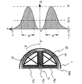
図6は、磁場発生手段によって発生される交番磁束の発生の様子を模式的に表したものである。磁束Cは発生した交番磁束の一部を表す。磁性コア17a,17b,17cに導かれた交番磁束Cは、磁性コア17aと磁性コア17bとの間、そして磁性コア17aと磁性コア17cとの間において定着フィルム10の発熱層1に渦電流を発生させる。この渦電流は、発熱層1の固有抵抗によって、発熱層1にジュール熱(渦電流損)を発生させる。
【0057】
発熱量Qは発熱層1を通る磁束Cの密度によって決まり、図6のグラフような分布を示す。図6に示すグラフは、縦軸が磁性コア17aの中心を0とした角度θで表した定着フィルム10における円周方向の位置を示し、横軸が定着フィルム10の発熱層1での発熱量Qを示す。ここで、発熱域Hは最大発熱量をQとし、発熱量がQ/e以上の領域と定義する(eは自然対数の底)。これは、定着プロセスに必要な発熱量が得られる領域である。
【0058】
この定着ニップ部Nの温度は、温度検知手段26(図2)を含む不図示の温調系により励磁コイル18に対する電流供給が制御されることで所定の温度が維持されるように温調される。温度検知手段26は定着フィルム10の温度を検知するサーミスタなどの温度センサであり、本例においてはサーミスタで測定した定着フィルム10の温度情報を基に定着ニップ部Nの温度を制御するようにしている。
【0059】
(4)定着フィルム10
図7は、本実施形態例における定定着フィルム10の層構成模型図である。
【0060】
本実施形態の定着フィルム10は、基層となる電磁誘導発熱性の金属フィルム等でできた発熱層1と、その外面に積層した弾性層2と、その外面に積層した離型層3と、発熱層1の内面に積層した摺動層4の複合構造のものである。
【0061】
発熱層1と弾性層2との間の接着、弾性層2と離型層3との間の接着、離型層3と摺動層4との間の接着のために、各層間にプライマー層(図示せず)を設けてもよい。
【0062】
略円筒形状である定着フィルム10において、摺動層4が内面側であり、離型層3が外面側である。
【0063】
上述したように、発熱層1に交番磁束が作用することにより、発熱層1に渦電流が発生して発熱層1が発熱する。この熱が弾性層2、離型層3に伝達されて、定着フィルム10全体が加熱され、定着ニップ部Nに通紙される記録材Pを加熱してトナーt画像の加熱定着がなされる。
【0064】
a.発熱層1
発熱層1としては、磁性及び非磁性の金属を用いることができるが、磁性金属が好ましく用いられる。このような磁性金属としては、ニッケル、鉄、強磁性ステンレス、ニッケル−コバルト合金、パーマロイといった強磁性体の金属が好ましく用いられる。又、定着フィルム10回転時に受ける繰り返しの屈曲応力による金属疲労を防ぐために、ニッケル中にマンガンを添加した部材を用いるのも良い。
【0065】
発熱層1の厚さは、次の式で表される表皮深さσ[m]より厚く、且つ200μm以下にすることが好ましい。発熱層1の厚さをこの範囲とすれば、発熱層1が電磁波を効率よく吸収することができるため、効率良く発熱させることができる。
【0066】
σ=503×(ρ/fμ)1/2 …(1)
ここで、fは励磁回路の周波数[Hz]、μは発熱層1の透磁率、ρは発熱層1の固有抵抗[Ωm]である。
【0067】
この表皮深さσは、電磁誘導で使われる電磁波の吸収の深さを示しており、これより深いところでは電磁波の強度は1/e以下になっている。逆にいうと殆どのエネルギーはこの深さまでで吸収されている(図8に示した発熱層深さと電磁波強度の関係を参照)。
【0068】
発熱層1の厚さは、より好ましくは1〜100μmがよい。発熱層1の厚みが上記範囲よりも薄い場合には、ほとんどの電磁エネルギーが吸収しきれないため効率が悪くなる。又、発熱層1が上記範囲よりも厚い場合には、発熱層1の剛性が高くなりすぎ、又、屈曲性が悪くなり回転体として使用するには現実的でなくなる。
【0069】
b.弾性層2
弾性層2は、シリコーンゴム、フッ素ゴム、フルオロシリコーンゴム等の、耐熱性、熱伝導率が良い材質が好ましく用いられる。
【0070】
弾性層2の厚さは、定着画像品質を保証するために10〜500μmであることが好ましい。カラー画像を印刷する場合、特に写真画像等では、記録材P上で大きな面積に渡ってベタ画像が形成される。この場合、記録材Pの凹凸或いはトナー層tの凹凸に加熱面(離型層3)が追従できないと加熱ムラが発生し、伝熱量が多い部分と少ない部分で画像に光沢ムラが発生する。即ち、伝熱量が多い部分は光沢度が高く、伝熱量が少ない部分では光沢度が低くなる。弾性層2の厚さが上記範囲よりも小さい場合には、上記離型層3が記録材P或いはトナー層tの凹凸に追従しきれず、画像光沢ムラが発生してしまう。又、弾性層2が上記範囲よりも大きすぎる場合には、弾性層2の熱抵抗が大きくなりすぎ、クイックスタートを実現するのが難しくなる。この弾性層2の厚さは、より好ましくは50〜500μmが良い。
【0071】
弾性層2は、硬度が高すぎると記録材P或いはトナー層tの凹凸に追従しきれず画像光沢ムラが発生してしまう。そこで、弾性層2の硬度としては60゜(JIS−A)以下、より好ましくは45゜(JIS−A)以下がよい。
【0072】
弾性層2の熱伝導率λは、2.5×10⁻¹〜8.4×10⁻¹W/m・℃であることが好ましい。熱伝導率λが上記範囲よりも小さい場合には、熱抵抗が大きすぎて、定着フィルム10の表層(離型層3)における温度上昇が遅くなる。熱伝導率λが上記範囲よりも大きい場合には、弾性層2の硬度が高くなりすぎたり、圧縮永久歪みが発生しやすくなる。より好ましくは3.3×10-1〜6.3×10-1W/m・℃が良い。
【0073】
c.離型層3
離型層3は、フッ素樹脂、シリコーン樹脂、フルオロシリコーンゴム、フッ素ゴム、シリコーンゴム、PFA、PTFE、FEP等の離型性且つ耐熱性のよい材料を用いることが好ましい。
【0074】
離型層3の厚さは1〜100μmが好ましい。離型層3の厚さが上記範囲よりも薄い場合には、塗膜の塗ムラが生じ、離型性の悪い部分が発生したり、耐久性が不足するといった問題が発生する。又、離型層3の厚さが上記範囲よりも厚い場合には、熱伝導が悪化する。特に、離型層3に樹脂系の材質を用いた場合は、離型層3の硬度が高くなりすぎて、弾性層2の効果がなくなってしまう。
と定着フィルム10との摺動抵抗を軽減することができる。
【0075】
d.摺動層4
図7に示すように、定着フィルム10の構成において、発熱層1の弾性層2とは反対面側に摺動層4を設けている。
【0076】
摺動層4としては、フッ素樹脂、ポリイミド樹脂、ポリアミド樹脂、ポリアミドイミド樹脂、PEEK樹脂、PES樹脂、PPS樹脂、PFA樹脂、PTFE樹脂、FEP樹脂などの摺動性が高く、耐熱性のある樹脂がよい。
【0077】
摺動層4を設けることにより、定着装置100の使用初期において回転駆動トルク(駆動ローラとしての加圧ローラ軸におけるトルク)を低く抑えられることに加え、定着フィルム10の発熱層1の摩耗を防ぐことができるため、定着装置100を長時間使用しても回転駆動トルクの上昇を抑えることができる。
【0078】
摺動層4は、発熱層1に発生した熱が定着フィルムの内側に向かわないように断熱する効果もあるため、摺動層4がない場合と比較して記録材P側への熱供給効率が良くなる。よって、消費電力を抑えることもできる。
【0079】
また、摺動層4の厚さとしては10〜1000μmが好ましい。摺動層4の厚さが10μmよりも小さい場合には耐久性が不足するうえ、断熱性も小さい。一方、1000μmを超えると磁性コア17及び励磁コイル18から発熱層1距離が大きくなり、磁束が十分に発熱層1に吸収されなくなる。
【0080】
(5)記録材の紙シワ、後端ハネ発生防止対策
本実施の形態では、図10に示すようにフィルムガイド部材16は定着ニップ面側の表面が平面ではなく、下に凸の正クラウン形状を有している。フィルムガイド部材16の正クラウン量はCRとして表され、フィルムガイド部材16は点線で示した直線に対して最大部でCRの高さだけ膨らんでおり、本実施の形態では正クラウン量CRの大きさは600μmに設定されている。なお、摺動部材40はフィルムガイド部材16に貼り付けられており、摺動部材40もフィルムガイド部材16の表面形状に倣って正クラウン形状となっている。本実施例においては、端部の測定位置は中央から100mmの位置とし、便宜上長手中央部と端部の高さ差CRを用いて説明する。
【0081】
また加圧ローラ30についても同様に、端部の測定位置は長手中央から100mmの位置とし、逆クラウン量をCR′として説明をおこなう。
【0082】
単位長さ当たりの正クラウン量cr(図9参照)と本実施例で用いるCRとの関係は、端部の位置を中央から100mmの位置としたことから、
100×1000cr=CR(μm)
また、単位長さ当たりの逆クラウン量cr′(図9参照)と本実施例で用いるCR′との関係は、端部の位置を中央から100mmの位置としたことから、
100×1000cr′=CR′(μm)
となる。
【0083】
フィルムガイド部材16の正クラウン量CRの測定方法について以下に述べる。
【0084】
フィルムガイド部材16の上下を逆にしてこれを水平な定盤の上に置き、摺動部材40表面をハイトゲージで測定する。また、加圧ローラ30については、レーザ外径測長機で逆クラウン量を測定する。
【0085】
フィルムガイド部材16の正クラウン量CRは、フィルムガイド部材16の定着ニップ面側の長手中央部と長手端部の高さの差として定義され、加圧ローラ30の逆クラウン量CR′は加圧ローラ30の長手中央部の外径D1と端部の外径D2との差から、(D2−D1)/2で定義される。なお、本実施の形態では、加圧ローラ30の逆クラウン量CR′は100μmに設定されている。
【0086】
以上のように、本実施例ではフィルムガイド部材16の定着ニップ面を正クラウン形状に、加圧ローラ30を逆クラウン形状に設定した。フィルムガイド部材16の正クラウン量CR及び加圧ローラ30の逆クラウン量CR′の大きさと、記録材Pの紙シワ及び後端ハネの発生との関係を表に示す。
【0087】
なお、本実験は気温30℃、湿度80%の環境で、記録材Pとして64g/m2の紙を使用した。
【0088】
【表1】

表1によれば、フィルムガイド部材16の正クラウン量CRに対して加圧ローラ30の逆クラウン量CR′が大きい場合、紙シワが発生しにくくなり、逆にCR′が小さい場合には後端ハネが発生しにくくなる。
【0090】
具体的には、加圧ローラ30の逆クラウン75μmの場合を例にとり、フィルムガイド部材16の正クラウン量CRが300μmの時、500μmの時、750μmの時を比較して説明する。
【0091】
フィルムガイド部材16の正クラウン量CRを500μmから300μmにすることにより、紙シワは発生しないが、後端ハネのレベルが悪化してくる。一方で、正クラウン量CRを500μmから750μmにすることにより、後端ハネは発生しないが、紙シワがまれに発生するようになる。
【0092】
正クラウン量CRが500μmの時は、紙を適度に両側に引っ張ることにより、紙シワを防止し、かつ後端ハネが画像に影響を及ぼさないレベルに抑えられている。
【0093】
表1のようになる原理としては、加圧ローラ30の逆クラウン量CR′に対してフィルムガイド部材16の正クラウン量CRが大きくなると、定着フィルム10を介したフィルムガイド部材16と加圧ローラ30の圧接力が、長手方向の中央部が端部に対して高い構成となり、中央部の搬送力が増すために紙シワに対して不利になる。
【0094】
逆に、逆クラウン量CR′に対して正クラウン量CRを小さくすると、フィルムガイド部材16と加圧ローラ30の圧接力が、中央部に対して端部が高い構成となるため、端部の紙搬送力が大きくなり、紙をより両側に引っ張る構成となるため、紙シワは防止できるが、後端ハネやそれに伴う画像不良を発生させる。
【0095】
少なくとも、端部測定位置を中央から100mmとした時、
100≦CR−4CR′≦400
を満たすフィルムガイド部材16と加圧ローラ30の組み合わせの時に、紙シワ及び後端ハネのない良好な画像が得られた。
【0096】
次に、定着ニップNは定着フィルム10を介してフィルムガイド部材16(40)と加圧ローラ30の圧接により形成され、加圧ローラ30軸線方向においては、図11のような形状をなしている。定着ニップ幅は定着性などに影響を及ぼす。
【0097】
フィルムガイド部材16の正クラウン量CR及び加圧ローラ30の逆クラウン量CR′の大きさと、定着ニップ幅との関係を表2に示す。
【0098】
ただし、表中の数値は、長手方向端部のニップ幅W2から、中央部のニップ幅W1の値を引いたものである。
【0099】
【表2】
加圧ローラ30の逆クラウン量CR′毎に、紙シワも後端ハネも発生させない、適切なフィルムガイド部材16のクラウン量CRは異なるが、その時の定着ニップ形状は、逆クラウン量CR′が大きい時は中凸ニップ、逆クラウン量CR′が小さい時には中凹ニップとなっていることが、表2よりわかる。
【0101】
例えば、加圧ローラ30の逆クラウン量CR′が0μmの時、フィルムガイド部材16の逆クラウン量CRが0μmでも紙シワや後端ハネの発生は見られなかったが、ニップ形状が端部と中央部で1.8mm異なり、中央部のニップ幅が5.5mmであり、画像中央部の光沢度が低い、ムラのある画像となった。逆に逆クラウンCR′が大きくなると、適正なニップ形状が中凸となり、画像端部の定着性が悪化するなどの問題が発生する。
【0102】
中央部のニップ幅W1と端部のニップ幅W2の差が0.5以内の時に、定着性及び光沢度の均一性が高いことがわかった。
【0103】
補足として、フィルムガイド部材16と加圧ローラ30は両端において加圧されるため、樹脂製のフィルムガイド部材16は正クラウンを打ち消す方向に、加圧ローラの芯金30aは逆クラウンを大きくする方向に撓む。フィルムガイド部材16の正クラウンCRが0μm、加圧ローラ30の逆クラウンCR′が0μmのときに、中凹ニップとなるのはそのためである。
【0105】
〈第2の実施形態例〉
図12は本実施形態例の画像加熱定着装置の要部の横断模型図である。
【0106】
16cは横断面略半円弧状樋型の耐熱性・断熱性のフィルムガイド、12は加熱体としてのセラミックヒータであり、フィルムガイド16cの下面の略中央部にガイド長手に沿って形成具備させた溝部に嵌入して固定支持させてある。
【0107】
11は円筒状もしくはエンドレス状で耐熱性の、金属層を有する定着フィルムである。前記定着フィルム11はフィルムガイド16cにルーズに外嵌させてある。
【0108】
定着フィルム11の基層として、より強度の高い金属フィルムを基層として用いることによって定着フィルム11の剛性が増し、大きなねじれ力が定着フィルム11に生じた場合も破損しにくく、本実施例の定着フィルム11は高速高荷重の定着装置に適している。
【0109】
前述した第1の実施形態例と同様、基層として金属フィルムを用いた場合、定着フィルム11の内面には摺動層としてポリイミド等の樹脂層を設けることが好ましい。また、表層には離型性の良いPFA樹脂のような離型層を設けることが好ましい。また、金属層と離型層の間に弾性層を設けてもよい。
【0110】
また、熱伝導性の高い金属フィルムを基層とする定着フィルムを用いることにより、発熱体で発生した熱を効率よく紙に伝達することができるメリットがあり、この点においても連続プリントで定着フィルム温度が低下しやすい高速プリンタに適している。用いられる金属材料としてはNi、SUS等が好ましい。
【0111】
22はフィルムガイド16cの内側に挿通した加圧用剛性ステイである。
【0112】
定着ニップNを形成するための加圧手段及び定着フィルム端部の保持手段については第1の実施形態例と同様の構成を取りここでの説明は省略する。
【0113】
加圧ローラ30は駆動手段Mにより矢示の反時計方向に回転駆動される。この加圧ローラ30の回転駆動による前記加圧ローラ30と定着フィルム11の外面との摩擦力で定着フィルム11に回転力が作用して、前記定着フィルム11がその内面が定着ニップ部Nにおいてセラミックヒータ12の下面に密着して摺動しながら矢示の時計方向に加圧ローラ30の回転周速度にほぼ対応した周速度をもってフィルムガイド16cの外回りを回転状態になる。
【0114】
本実施例においても、加圧ローラ30は逆クラウン形状であり、ローラ長手中央部の外径D1と、ローラ長手中央部の位置からローラ長手に沿って100mm離れた位置の外径D2と差(D2−D1)/2を逆クラウン量CR′(μm)、フィルムガイド16cの加圧ローラ30との摺動部はクラウン形状であり、ガイド部材長手中央部の位置と、ガイド部材長手中央部の位置からガイド部材長手に沿って100mm離れた位置との高さの差を正クラウン量CR(μm)、とした場合、
100(μm)≦CR−4CR′≦400(μm)
かつ、定着ニップ中央部の幅をW1、端部のニップ幅をW2とした場合、
−0.5≦W2−W1≦0.5
を満たすような、第1の実施形態例と同様の構成のフィルムガイド16cの摺動面形状と加圧ローラ30の形状の組み合わせにより、記録材Pには紙シワ及び後端ハネが生じさせず、かつ定着性及び光沢度の均一な画像を得ることができる。
【0115】
このようなフィルム加熱方式の装置は、加熱体として熱低容量のセラミックヒータや電磁誘導発熱性ヒータを、フィルムとして低熱容量、耐熱性のある薄い材料を用いることができ、熱容量が大きい定着ローラを用いる熱ローラ方式の装置に比べて格段に省電力化、ウエイトタイム短縮化が可能であり、クイックスタート性があり、機内昇温も抑えられる等の利点がある。
【0116】
〈その他の実施形態例〉
1)電磁誘導発熱性の定着フィルム10は、モノクロあるいは1パスマルチカラー画像などの加熱定着用の場合は弾性層2を省略した形態のものとすることもできる。発熱層1は樹脂に金属フィラーを混入して構成したものとすることもできる。発熱層単層の部材とすることもできる。
2)本発明の加熱装置は実施形態例の画像加熱定着装置としてに限らず、画像を担持した記録材を加熱してつや等の表面性を改質する像加熱装置、仮定着する像加熱装置、その他、被加熱材の加熱乾燥装置、加熱ラミネート装置など、広く被加熱材を加熱処理する手段・装置として使用できる。
【0117】
【発明の効果】
以上説明したように、本発明によれば、回転体と、該回転体を回転体の内側において支持する回転体ガイド部材と、回転体を介して回転体ガイド部材とニップを形成するとともに回転体を従動回転させる加圧駆動ローラとを有し、前記回転体は前記回転体ガイド部材と摺動回転し、前記ニップで被加熱材を挟持搬送して加熱する加熱装置において、ニップ部内で被加熱材を加熱・搬送しながら適度に両側に引っ張ることができて、被加熱材の加熱・搬送時に被加熱材にシワ及び後端ハネを発生させないようにすることができる。像加熱装置にあっては記録材上の画像定着・搬送時に記録材に紙シワ及び後端ハネを発生させることなく、しかも定着性や光沢度の均一な画像を得ることができる。
【図面の簡単な説明】
【図1】 第1の実施形態例に用いた画像形成装置の概略構成図
【図2】 加熱装置としての像加熱装置の要部の横断側面模型図
【図3】 同じく要部の正面模型図
【図4】 同じく要部の横断正面模型図
【図5】 内部に磁場発生手段を配設支持させたフィルムガイド部材半体の斜視模型図
【図6】 磁場発生手段と発熱量Qの関係を示した図
【図7】 電磁誘導発熱性の定着フィルムの層構成模型図
【図8】 発熱層深さと電磁波強度の関係を示したグラフ
【図9】 フィルムガイド部材と加圧ローラの正面図1
【図10】 フィルムガイド部材と加圧ローラの正面図2
【図11】 像加熱装置の定着ニップ説明図
【図12】 第2の実施形態例を示した図
【符号の説明】
1 発熱層
2 弾性層
3 離型層
4 断熱層
10 定着フィルム
12 セラミックヒータ
16 フィルムガイド部材
17 磁性コア
18 励磁コイル
22 加圧用剛性ステイ
23a・23b 定着フィルム端部の規制・保持用フランジ部材
26 温度検知素子(サーミスタ)
30 加圧部材としての加圧ローラ
40 摺動部材
N 定着ニップ
CR 正クラウン
CR′ 逆クラウン[0001]
BACKGROUND OF THE INVENTION
The present invention relates to a heating apparatus that pressurizes and heats a material to be heated, and an electrophotographic apparatus and electrostatic recording apparatus provided as an image heating apparatus that heats and fixes an unfixed image formed and supported on the recording material. The present invention relates to an image forming apparatus.
[0002]
[Prior art]
For convenience, an image heating apparatus (fixing apparatus) that is provided in an image forming apparatus such as a copying machine or a printer and that heats and fixes a toner image on a recording material will be described as an example.
[0003]
In an image forming apparatus, a recording material (transfer material sheet, electrofax sheet, electrostatic recording paper, OHP sheet, printing paper, format, etc., in an appropriate image forming process means such as an electrophotographic process, electrostatic recording process, magnetic recording process, etc. As a fixing device that heats and fixes an unfixed image (toner image) of target image information formed and supported by a transfer method or a direct method on paper or the like as a permanently fixed image on a recording material surface, a heat roller type device is widely used. It was used.
[0004]
Recently, film heating systems have been put into practical use from the viewpoint of quick start and energy saving. There has also been proposed an electromagnetic induction heating type apparatus in which the film itself generates heat.
[0005]
In recent years, there has been a strong demand for higher speed in fixing devices, and at the same time, miniaturization of image forming apparatuses has been demanded. There is also an increasing demand for color image forming apparatuses. A color image forming apparatus that uses a small-diameter fixing roller and a pressure roller to reduce the size of the apparatus, and the recording material conveyance speed is high, in order to permanently fix an unfixed toner image on the recording material surface. Therefore, it is necessary to apply a sufficient amount of heat and pressure to the recording material.
[0006]
The film heating type fixing device having a metal layer is characterized by higher strength and higher thermal conductivity than the resin film type, and can easily cope with higher speeds.
[0007]
Japanese Patent Application Laid-Open No. 7-114276 proposes a heating device that generates an eddy current in a film itself or a conductive member close to the film and generates heat by Joule heat.
[0008]
This electromagnetic induction heating method can increase the efficiency of energy consumption since the film itself generates heat, and can cope with a higher speed.
[0009]
In a heating device of a film heating method or an electromagnetic induction heating method using a film, as a driving method of a cylindrical or endless film film as a rotating body, a film guide member that guides the inner peripheral surface of the film and a pressure roller The pressure roller is driven by the method of rotating the pressure-contacted film by the rotational driving of the pressure roller (pressure roller driving method) or by driving the endless film film stretched by the driving roller and the tension roller. There are those that rotate the follower.
[0010]
[Problems to be solved by the invention]
However, in a heat fixing device using a film having a metal layer as a rotating body, when the paper as a recording material passes through the fixing device, the paper may be wrinkled in the fixing nip portion. This wrinkle is particularly likely to occur on thin paper.
[0011]
Conventionally, in a heat roller type heat fixing device that is generally used, by providing an inverted crown shape on the outer diameter of the fixing roller, the paper conveyance speed in the fixing nip is fast at both ends and slow at the center. Thus, a technique is employed in which a force for pulling the paper to both sides is generated, thereby preventing the occurrence of paper wrinkles.
[0012]
On the other hand, in a heat fixing apparatus using a film having a metal layer as a rotating body, it is difficult to give the fixing film corresponding to the heat roller a reverse crown shape. In addition, by attaching a reverse crown shape to the sliding part of the fixing film guide member that holds the fixing film with the fixing film, it is possible to prevent the occurrence of paper wrinkles, but the fixing nip has an extremely concave shape. Inconveniences such as low glossiness at the center of the image occurred.
[0013]
Also, when the force pulling the paper to both sides is too strong to prevent paper wrinkling, the rear edge of the paper may jump and cause image defects such as rubbing.
[0014]
The present invention has been made in view of the above problems, and forms a rotator, a rotator guide member that supports the rotator inside the rotator, and a nip with the rotator guide member via the rotator. A heating device having a pressure driving roller that rotates the rotating body in a driven manner, the rotating body slidingly rotating with the rotating body guide member, and sandwiching and transporting the heated material at the nip to heat the heated material; In the image heating device, to prevent the generation of wrinkles and trailing edge splashes on the heated material during heating / conveying of images, it is necessary to generate paper wrinkles and trailing edge splashes on the recording material during image fixing / conveying on the recording material. An object is to obtain an image having uniform fixing properties and glossiness.
[0015]
[Means for Solving the Problems]
The present invention is a heating device and an image forming apparatus having the following configurations.
[0016]
(1) A rotator, a rotator guide member that supports the rotator inside the rotator, a pressure drive roller that forms a nip with the rotator guide member via the rotator and rotates the rotator in a driven manner. In the heating apparatus, the rotating body slides and rotates with the rotating body guide member, and heats the material to be heated in the nip.
The pressure driving roller has an inverted crown shape, and is different from an outer diameter D1 of the roller longitudinal center portion and an outer diameter D2 at a
The sliding part of the rotating body guide member with the rotating body has a crown shape, and the height between the position of the guide member longitudinal center and the
If
100 (μm) ≦ CR-4CR ′ ≦ 400 (μm)
A heating device characterized by the above.
[0017]
(2) The width of the central portion of the nip in the axial direction of the pressure driving roller is W1 [mm],
When the width of the end is W2 [mm]
−0.5 ≦ W2−W1 ≦ 0.5
(1) The heating apparatus according to (1).
[0018]
(3) The heating device according to (1) or (2), wherein the rotating body includes a metal layer.
[0019]
(4) The heating device according to any one of (1) to (3), wherein the rotating body and the pressure driving roller have a release layer on a surface thereof.
[0020]
(5) The heating device according to (4), wherein the release layer of the rotating body and the pressure driving roller is made of PFA resin.
[0021]
(6) The heating device according to any one of (1) to (5), wherein the rotary body and the pressure driving roller have a linear pressure of 60 g / mm to 180 g / mm at a nip portion.
[0022]
(7) The pressure driving roller has a product hardness in a molded state of 40 ° to 70 ° in Asker-C hardness (9.8 N load), according to any one of (1) to (6) The heating device described.
[0023]
(8) The heating device according to any one of (1) to (7), wherein the rotating body generates induction heat by a magnetic flux generated by magnetic flux generation means.
[0024]
(9) The rotating body guide member that supports the rotating body holds an exciting coil as the magnetic flux generating means and a high permeability magnetic member that guides the magnetic flux to the rotating body. Heating device.
[0025]
(10) The heating apparatus according to any one of (1) to (9), wherein the heated material is a recording material carrying an image, and the apparatus is an image heating apparatus that heats the image.
[0026]
(11) Image forming means for forming and supporting an image on a recording material and image heating means for heating the image formed and supported on the recording material, wherein the image heating means is any one of (1) to (9) An image forming apparatus, which is the heating apparatus described above.
[0027]
DETAILED DESCRIPTION OF THE INVENTION
<First Embodiment>
(1) Example of image forming apparatus
FIG. 1 is a schematic configuration diagram of an example of an image forming apparatus. The image forming apparatus of this example is an electrophotographic color printer.
[0028]
[0029]
Next, the charged surface is subjected to scanning exposure processing of target image information by a
[0030]
In the case of full-color image formation, scanning exposure and latent image formation are performed on a first color separation component image, for example, a yellow component image, in a target full-color image. The yellow toner image is developed by the operation of 104Y. The yellow toner image is transferred onto the surface of the
[0031]
The process cycle of charging, scanning exposure, development, primary transfer, and cleaning as described above is the second color separation component image of the target full color image (for example, the magenta component image, the
[0032]
The
[0033]
The color toner image formed on the surface of the
[0034]
The recording material P that has passed through the secondary transfer portion T2 is separated from the surface of the
[0035]
The
[0036]
Also, the
[0037]
This image forming apparatus can also execute a mono-color image print mode such as a monochrome image. A double-sided image print mode or a multiple image print mode can also be executed.
[0038]
In the double-sided image print mode, the recording material P on which the first-side image has been printed exiting the fixing
[0039]
In the multiple image print mode, the recording material P after the first image printed out of the fixing
[0040]
(2)
In this example, the fixing
[0041]
2 is a cross-sectional model view of the main part of the fixing
[0042]
This
[0043]
The cylindrical
[0044]
The
[0045]
The product hardness in the molding state of the
[0046]
The
[0047]
The fixing
[0048]
The
[0049]
In order to reduce the mutual sliding frictional force between the lower surface of the
[0050]
(3) Magnetic field generation means
The
[0051]
The
[0052]
As the covering member for performing the insulating coating, it is preferable to use a coating having heat resistance in consideration of heat conduction due to heat generation of the fixing
[0053]
The
[0054]
An insulating member 19 is disposed between the magnetic field generating means 17a, 17b, 17c and 18 and the pressurizing
[0055]
An
[0056]
FIG. 6 schematically shows how the alternating magnetic flux generated by the magnetic field generating means is generated. A magnetic flux C represents a part of the generated alternating magnetic flux. The alternating magnetic flux C guided to the
[0057]
The calorific value Q is determined by the density of the magnetic flux C passing through the
[0058]
The temperature of the fixing nip portion N is controlled so that a predetermined temperature is maintained by controlling the current supply to the
[0059]
(4) Fixing
FIG. 7 is a layer configuration model diagram of the
[0060]
The fixing
[0061]
For adhesion between the
[0062]
In the fixing
[0063]
As described above, when the alternating magnetic flux acts on the
[0064]
a.
As the
[0065]
The thickness of the
[0066]
σ = 503 × (ρ / fμ) 1/2 ... (1)
Here, f is the frequency [Hz] of the excitation circuit, μ is the magnetic permeability of the
[0067]
This skin depth σ indicates the depth of absorption of electromagnetic waves used for electromagnetic induction, and the intensity of the electromagnetic waves is 1 / e or less deeper than this. Conversely, most of the energy is absorbed up to this depth (see the relationship between the heat generation layer depth and the electromagnetic wave intensity shown in FIG. 8).
[0068]
The thickness of the
[0069]
b. Elastic layer 2
The elastic layer 2 is preferably made of a material having good heat resistance and thermal conductivity, such as silicone rubber, fluorine rubber, and fluorosilicone rubber.
[0070]
The thickness of the elastic layer 2 is preferably 10 to 500 μm in order to guarantee the fixed image quality. When a color image is printed, a solid image is formed over a large area on the recording material P, particularly in a photographic image. In this case, if the heating surface (release layer 3) cannot follow the unevenness of the recording material P or the unevenness of the toner layer t, heating unevenness occurs, and gloss unevenness occurs in the image where the heat transfer amount is large and small. That is, the glossiness is high in the portion where the heat transfer amount is large, and the glossiness is low in the portion where the heat transfer amount is small. When the thickness of the elastic layer 2 is smaller than the above range, the release layer 3 cannot follow the unevenness of the recording material P or the toner layer t, and image gloss unevenness occurs. On the other hand, when the elastic layer 2 is too larger than the above range, the thermal resistance of the elastic layer 2 becomes too large, making it difficult to realize a quick start. The thickness of the elastic layer 2 is more preferably 50 to 500 μm.
[0071]
If the elastic layer 2 is too hard, it cannot follow the unevenness of the recording material P or the toner layer t, and unevenness in image gloss occurs. Therefore, the hardness of the elastic layer 2 is 60 ° (JIS-A) or less, more preferably 45 ° (JIS-A) or less.
[0072]
The thermal conductivity λ of the elastic layer 2 is 2.5 × 10 -1 ~ 8.4 × 10 -1 W / m · ° C. is preferable. When the thermal conductivity λ is smaller than the above range, the thermal resistance is too large, and the temperature rise in the surface layer (release layer 3) of the fixing
[0073]
c. Release layer 3
The release layer 3 is preferably made of a material having good release properties and heat resistance such as fluororesin, silicone resin, fluorosilicone rubber, fluororubber, silicone rubber, PFA, PTFE, and FEP.
[0074]
The thickness of the release layer 3 is preferably 1 to 100 μm. If the thickness of the release layer 3 is thinner than the above range, uneven coating of the coating film occurs, causing a problem that a part having poor release property is generated or durability is insufficient. Moreover, when the thickness of the release layer 3 is thicker than the above range, the heat conduction is deteriorated. In particular, when a resin material is used for the release layer 3, the hardness of the release layer 3 becomes too high and the effect of the elastic layer 2 is lost.
And the sliding resistance between the fixing
[0075]
d. Sliding layer 4
As shown in FIG. 7, in the configuration of the fixing
[0076]
As the sliding layer 4, a resin having high slidability and heat resistance such as fluororesin, polyimide resin, polyamide resin, polyamideimide resin, PEEK resin, PES resin, PPS resin, PFA resin, PTFE resin, FEP resin, etc. Is good.
[0077]
By providing the sliding layer 4, the rotational driving torque (torque at the pressure roller shaft as a driving roller) can be kept low in the initial use of the fixing
[0078]
Since the sliding layer 4 also has an effect of heat insulation so that the heat generated in the
[0079]
Further, the thickness of the sliding layer 4 is preferably 10 to 1000 μm. When the thickness of the sliding layer 4 is less than 10 μm, the durability is insufficient and the heat insulation is also small. On the other hand, if the thickness exceeds 1000 μm, the distance from the magnetic core 17 and the
[0080]
(5) Measures to prevent paper wrinkles and trailing edge splashes on recording
In the present embodiment, as shown in FIG. 10, the
[0081]
Similarly, for the
[0082]
The relationship between the amount of positive crown cr per unit length (see FIG. 9) and the CR used in this example is that the position of the end is set to a
100 × 1000 cr = CR (μm)
Further, the relationship between the reverse crown amount cr ′ per unit length (see FIG. 9) and the CR ′ used in the present embodiment is that the position of the end is 100 mm from the center.
100 × 1000 cr ′ = CR ′ (μm)
It becomes.
[0083]
A method of measuring the positive crown amount CR of the
[0084]
The
[0085]
The normal crown amount CR of the
[0086]
As described above, in this embodiment, the fixing nip surface of the
[0087]
In this experiment, the recording material P was 64 g / m in an environment where the temperature was 30 ° C. and the humidity was 80%. 2 Paper was used.
[0088]
[Table 1]
According to Table 1, when the reverse crown amount CR ′ of the
[0090]
Specifically, the case where the reverse crown of the
[0091]
By setting the positive crown amount CR of the
[0092]
When the positive crown amount CR is 500 μm, the paper is moderately pulled to both sides to prevent paper wrinkling and the level at which the trailing edge splash does not affect the image.
[0093]
As the principle shown in Table 1, when the normal crown amount CR of the
[0094]
On the other hand, if the normal crown amount CR is reduced with respect to the reverse crown amount CR ′, the pressure contact force between the
[0095]
At least when the edge measurement position is 100 mm from the center,
100 ≦ CR-4CR ′ ≦ 400
When the
[0096]
Next, the fixing nip N is formed by pressure contact between the film guide member 16 (40) and the
[0097]
Table 2 shows the relationship between the size of the normal crown amount CR of the
[0098]
However, the numerical values in the table are obtained by subtracting the value of the nip width W1 at the central portion from the nip width W2 at the end portion in the longitudinal direction.
[0099]
[Table 2]
For each reverse crown amount CR ′ of the
[0101]
For example, when the reverse crown amount CR ′ of the
[0102]
It was found that when the difference between the nip width W1 at the central portion and the nip width W2 at the end portion is within 0.5, the uniformity of the fixing property and glossiness is high.
[0103]
As a supplement, since the
[0105]
<Second Embodiment>
FIG. 12 is a cross-sectional model view of the main part of the image heating and fixing apparatus of this embodiment.
[0106]
16c is a heat-resistant and heat-insulating film guide having a substantially semicircular arc shape in cross section, and 12 is a ceramic heater as a heating body, which is formed along the length of the guide at a substantially central portion of the lower surface of the
[0107]
[0108]
By using a stronger metal film as the base layer of the fixing
[0109]
As in the first embodiment described above, when a metal film is used as the base layer, it is preferable to provide a resin layer such as polyimide as a sliding layer on the inner surface of the fixing
[0110]
In addition, the use of a fixing film based on a metal film with high thermal conductivity has the advantage that the heat generated by the heating element can be efficiently transferred to the paper. It is suitable for high-speed printers that tend to degrade. Ni, SUS, etc. are preferable as the metal material used.
[0111]
[0112]
The pressurizing means for forming the fixing nip N and the holding means for the fixing film end have the same configuration as in the first embodiment, and the description thereof is omitted here.
[0113]
The
[0114]
Also in this embodiment, the
100 (μm) ≦ CR-4CR ′ ≦ 400 (μm)
When the width of the fixing nip central portion is W1 and the nip width of the end portion is W2,
−0.5 ≦ W2−W1 ≦ 0.5
By satisfying the combination of the sliding surface shape of the
[0115]
Such a film heating type apparatus can use a low heat capacity ceramic heater or an electromagnetic induction heat generating heater as a heating body, and a low heat capacity and heat resistant thin material as a film, and a fixing roller having a large heat capacity. Compared to the heat roller type apparatus used, there are advantages such as significantly reduced power consumption and shortened wait time, quick start performance, and suppression of temperature rise in the apparatus.
[0116]
<Other embodiment examples>
1) The electromagnetic induction heat-generating
2) The heating device of the present invention is not limited to the image heating and fixing device of the embodiment, but is an image heating device that heats a recording material carrying an image to improve surface properties such as gloss, an image heating device that is supposed to be worn, In addition, it can be widely used as a means / device for heat-treating a material to be heated, such as a heating / drying device or a heating laminating device.
[0117]
【The invention's effect】
As described above, according to the present invention, a rotating body, a rotating body guide member that supports the rotating body inside the rotating body, a nip is formed with the rotating body guide member via the rotating body, and the rotating body. And a pressure driving roller that rotates the driven member to rotate. The rotating member slides and rotates with the rotating member guide member, and heats the material to be heated by nipping and transporting the material to be heated in the nip. The material can be pulled to both sides appropriately while heating / conveying the material, so that the material to be heated can be prevented from being wrinkled and trailing end heated when the material to be heated is heated / conveyed. In the image heating apparatus, it is possible to obtain an image having a uniform fixing property and glossiness without generating paper wrinkles and trailing edge splashes on the recording material during image fixing and conveyance on the recording material.
[Brief description of the drawings]
FIG. 1 is a schematic configuration diagram of an image forming apparatus used in a first embodiment.
FIG. 2 is a cross-sectional side view of a main part of an image heating apparatus as a heating apparatus.
[Fig. 3] Front view of the main part
[Fig. 4] Cross-sectional front view of the main part
FIG. 5 is a schematic perspective view of a half film guide member in which a magnetic field generating means is disposed and supported.
FIG. 6 is a diagram showing the relationship between magnetic field generation means and calorific value Q
FIG. 7 is a model diagram of the layer structure of an electromagnetic induction heat-generating fixing film.
FIG. 8 is a graph showing the relationship between the heat generation layer depth and the electromagnetic wave intensity.
FIG. 9 is a front view of a film guide member and a pressure roller.
FIG. 10 is a front view of a film guide member and a pressure roller.
FIG. 11 is an explanatory diagram of a fixing nip of the image heating apparatus.
FIG. 12 is a diagram showing a second embodiment example
[Explanation of symbols]
1 Heat generation layer
2 Elastic layer
3 Release layer
4 Insulation layer
10 Fixing film
12 Ceramic heater
16 Film guide member
17 Magnetic core
18 Excitation coil
22 Rigid stay for pressurization
23a / 23b Flanging member for regulating / holding fixing film end
26 Temperature sensing element (thermistor)
30 Pressure roller as pressure member
40 Sliding member
N fixing nip
CR positive crown
CR 'reverse crown
Claims (11)
前記加圧駆動ローラは逆クラウン形状であり、ローラ長手中央部の外径D1と、ローラ長手中央部の位置からローラ長手に沿って100mm離れた位置の外径D2と差(D2−D1)/2を逆クラウン量CR′(μm)、
前記回転体ガイド部材の回転体との摺動部はクラウン形状であり、ガイド部材長手中央部の位置と、ガイド部材長手中央部の位置からガイド部材長手に沿って100mm離れた位置との高さの差を正クラウン量CR(μm)、
とした場合、
100(μm)≦CR−4CR′≦400(μm)
であることを特徴とする加熱装置。A rotating body, a rotating body guide member that supports the rotating body inside the rotating body, and a pressure drive roller that forms a nip with the rotating body guide member via the rotating body and that rotates the rotating body in a driven manner. In the heating device, the rotating body slides and rotates with the rotating body guide member, and the material to be heated is nipped and conveyed in the nip, and heated.
The pressure driving roller has an inverted crown shape, and is different from an outer diameter D1 of the roller longitudinal center portion and an outer diameter D2 at a position 100 mm away from the position of the roller longitudinal center portion along the roller length (D2-D1) / 2 is the reverse crown amount CR ′ (μm),
The sliding part of the rotating body guide member with the rotating body has a crown shape, and the height between the position of the guide member longitudinal center and the position 100 mm away from the position of the guide member longitudinal center along the guide member length. The difference between the positive crown amount CR (μm),
If
100 (μm) ≦ CR-4CR ′ ≦ 400 (μm)
A heating device characterized by the above.
端部の幅をW2[mm]とした場合、
−0.5≦W2−W1≦0.5
であることを特徴とする請求項1に記載の加熱装置。The width of the central portion of the nip in the axial direction of the pressure driving roller is W1 [mm],
When the width of the end is W2 [mm]
−0.5 ≦ W2−W1 ≦ 0.5
The heating apparatus according to claim 1, wherein:
Priority Applications (2)
| Application Number | Priority Date | Filing Date | Title |
|---|---|---|---|
| JP2002025263A JP3817482B2 (en) | 2002-02-01 | 2002-02-01 | Heating apparatus and image forming apparatus |
| US10/353,961 US6775509B2 (en) | 2002-02-01 | 2003-01-30 | Image heating apparatus |
Applications Claiming Priority (1)
| Application Number | Priority Date | Filing Date | Title |
|---|---|---|---|
| JP2002025263A JP3817482B2 (en) | 2002-02-01 | 2002-02-01 | Heating apparatus and image forming apparatus |
Publications (3)
| Publication Number | Publication Date |
|---|---|
| JP2003228246A JP2003228246A (en) | 2003-08-15 |
| JP2003228246A5 JP2003228246A5 (en) | 2005-07-28 |
| JP3817482B2 true JP3817482B2 (en) | 2006-09-06 |
Family
ID=27677807
Family Applications (1)
| Application Number | Title | Priority Date | Filing Date |
|---|---|---|---|
| JP2002025263A Expired - Lifetime JP3817482B2 (en) | 2002-02-01 | 2002-02-01 | Heating apparatus and image forming apparatus |
Country Status (2)
| Country | Link |
|---|---|
| US (1) | US6775509B2 (en) |
| JP (1) | JP3817482B2 (en) |
Cited By (4)
| Publication number | Priority date | Publication date | Assignee | Title |
|---|---|---|---|---|
| US9008548B2 (en) | 2013-03-29 | 2015-04-14 | Brother Kogyo Kabushiki Kaisha | Fixing device provided with reinforced nip member |
| US9091978B2 (en) | 2013-03-29 | 2015-07-28 | Brother Kogyo Kabushiki Kaisha | Fixing device provided with stay having rigidity distribution |
| US9116475B2 (en) | 2013-03-29 | 2015-08-25 | Brother Kogyo Kabushiki Kaisha | Fixing device fixing transferred developing agent image to sheet |
| US9188919B2 (en) | 2013-03-29 | 2015-11-17 | Brother Kogyo Kabushiki Kaisha | Fixing device provided with rotating member having concave shape |
Families Citing this family (23)
| Publication number | Priority date | Publication date | Assignee | Title |
|---|---|---|---|---|
| US7334876B2 (en) * | 2002-11-23 | 2008-02-26 | Silverbrook Research Pty Ltd | Printhead heaters with small surface area |
| US6755509B2 (en) * | 2002-11-23 | 2004-06-29 | Silverbrook Research Pty Ltd | Thermal ink jet printhead with suspended beam heater |
| US7581822B2 (en) | 2002-11-23 | 2009-09-01 | Silverbrook Research Pty Ltd | Inkjet printhead with low voltage ink vaporizing heaters |
| DE602004019373D1 (en) * | 2003-10-22 | 2009-03-26 | Ricoh Kk | Imaging process |
| JP4617140B2 (en) | 2003-11-27 | 2011-01-19 | キヤノン株式会社 | Image heating device |
| JP4537215B2 (en) * | 2004-02-03 | 2010-09-01 | キヤノン株式会社 | Image heating device |
| JP4418689B2 (en) * | 2004-02-04 | 2010-02-17 | キヤノン株式会社 | Image forming apparatus |
| JP4386262B2 (en) * | 2004-02-04 | 2009-12-16 | キヤノン株式会社 | Image forming apparatus |
| JP2005221676A (en) | 2004-02-04 | 2005-08-18 | Canon Inc | Image forming apparatus and its controlling method |
| JP2005221677A (en) * | 2004-02-04 | 2005-08-18 | Canon Inc | Image forming apparatus |
| US7403737B2 (en) * | 2004-12-21 | 2008-07-22 | Lexmark International, Inc. | Method of preventing media wrinkling |
| JP4981276B2 (en) * | 2005-08-03 | 2012-07-18 | キヤノン株式会社 | Fixing device |
| JP2009116128A (en) * | 2007-11-07 | 2009-05-28 | Fuji Xerox Co Ltd | Fixing device and image forming apparatus |
| JP5428920B2 (en) * | 2010-02-15 | 2014-02-26 | 株式会社リコー | Fixing device and image forming apparatus |
| JP2012108461A (en) * | 2010-05-28 | 2012-06-07 | Ricoh Co Ltd | Fixing device and image forming apparatus using the same |
| JP5928052B2 (en) * | 2012-03-23 | 2016-06-01 | 富士ゼロックス株式会社 | Fixing apparatus and image forming apparatus |
| JP2014025965A (en) * | 2012-07-24 | 2014-02-06 | Canon Inc | Image processing apparatus |
| JP5940510B2 (en) * | 2012-12-27 | 2016-06-29 | キヤノンファインテック株式会社 | Fixing apparatus and image forming apparatus |
| JP6463073B2 (en) | 2014-10-21 | 2019-01-30 | キヤノン株式会社 | Fixing device |
| JP6632291B2 (en) * | 2015-09-25 | 2020-01-22 | キヤノン株式会社 | Image heating device |
| JP6361625B2 (en) * | 2015-10-07 | 2018-07-25 | 京セラドキュメントソリューションズ株式会社 | Fixing apparatus and image forming apparatus |
| JP7086691B2 (en) * | 2018-04-19 | 2022-06-20 | キヤノン株式会社 | Image heating device and image forming device |
| US11047630B2 (en) * | 2018-05-14 | 2021-06-29 | Hewlett-Packard Development Company, L.P. | Fuser assemblies |
Family Cites Families (27)
| Publication number | Priority date | Publication date | Assignee | Title |
|---|---|---|---|---|
| US323789A (en) * | 1885-08-04 | Louis chevalliee | ||
| US656428A (en) * | 1900-05-18 | 1900-08-21 | William S Sherd | Twine-tension device. |
| JPH07104636B2 (en) * | 1989-04-03 | 1995-11-13 | キヤノン株式会社 | Fixing device |
| JPH03233586A (en) * | 1990-02-09 | 1991-10-17 | Canon Inc | Fixing device |
| US6005594A (en) * | 1990-03-26 | 1999-12-21 | Canon Kabushiki Kaisha | Fixing apparatus having a fixing roller with a non-adhesive surface layer |
| US5331385A (en) * | 1990-05-15 | 1994-07-19 | Canon Kabushiki Kaisha | Fixing rotatable member having conductive parting layer and fixing apparatus using same |
| US5319430A (en) * | 1993-01-04 | 1994-06-07 | Xerox Corporation | Fuser mechanism having crowned rolls |
| US5450181A (en) * | 1993-05-11 | 1995-09-12 | Canon Kabushiki Kaisha | Fixing device |
| JP3311111B2 (en) * | 1993-10-18 | 2002-08-05 | キヤノン株式会社 | Image heating device and rotating body for image heating |
| JP3039744B2 (en) * | 1993-11-19 | 2000-05-08 | キヤノン株式会社 | Image forming device |
| JP3065886B2 (en) * | 1994-04-28 | 2000-07-17 | キヤノン株式会社 | Fixing device |
| JPH09197864A (en) * | 1996-01-12 | 1997-07-31 | Canon Inc | Heating fixing device |
| US5689788A (en) * | 1996-03-22 | 1997-11-18 | Xerox Corporation | Heat and pressure roll fuser with substantially uniform velocity |
| JPH09325629A (en) * | 1996-05-31 | 1997-12-16 | Canon Inc | Heating device and image forming device |
| US6131010A (en) * | 1996-11-15 | 2000-10-10 | Canon Kabushiki Kaisha | Rotatable member having elastic layer and fixing apparatus having said rotatable member |
| US5889610A (en) * | 1996-12-31 | 1999-03-30 | Lucent Technologies Inc. | Optical protection switching system |
| JPH1124478A (en) * | 1997-07-04 | 1999-01-29 | Ricoh Co Ltd | Fixing device and roller therefor |
| JPH11109767A (en) * | 1997-08-04 | 1999-04-23 | Canon Inc | Image forming device |
| JP3937543B2 (en) * | 1997-12-26 | 2007-06-27 | キヤノン株式会社 | Image forming apparatus |
| JPH11249478A (en) * | 1998-03-06 | 1999-09-17 | Canon Inc | Fixing device |
| JP4371445B2 (en) * | 1998-06-05 | 2009-11-25 | キヤノン株式会社 | Image forming apparatus |
| JP2000221830A (en) * | 1999-02-01 | 2000-08-11 | Canon Inc | Fixing device and image forming device |
| JP4027011B2 (en) * | 1999-04-28 | 2007-12-26 | キヤノン株式会社 | Image forming apparatus |
| JP3634679B2 (en) * | 1999-07-30 | 2005-03-30 | キヤノン株式会社 | Heating device |
| US6229982B1 (en) * | 2000-04-27 | 2001-05-08 | Toshiba Tec Kabushiki Kaisha | Fixing apparatus, fixing method and image forming apparatus |
| JP2002082559A (en) * | 2000-06-22 | 2002-03-22 | Ricoh Co Ltd | Heating roller, its manufacturing method, heating device, fixing device and image forming device |
| US6564033B2 (en) | 2000-12-12 | 2003-05-13 | Canon Kabushiki Kaisha | Fixing belt and image heating and fixing apparatus |
-
2002
- 2002-02-01 JP JP2002025263A patent/JP3817482B2/en not_active Expired - Lifetime
-
2003
- 2003-01-30 US US10/353,961 patent/US6775509B2/en not_active Expired - Lifetime
Cited By (4)
| Publication number | Priority date | Publication date | Assignee | Title |
|---|---|---|---|---|
| US9008548B2 (en) | 2013-03-29 | 2015-04-14 | Brother Kogyo Kabushiki Kaisha | Fixing device provided with reinforced nip member |
| US9091978B2 (en) | 2013-03-29 | 2015-07-28 | Brother Kogyo Kabushiki Kaisha | Fixing device provided with stay having rigidity distribution |
| US9116475B2 (en) | 2013-03-29 | 2015-08-25 | Brother Kogyo Kabushiki Kaisha | Fixing device fixing transferred developing agent image to sheet |
| US9188919B2 (en) | 2013-03-29 | 2015-11-17 | Brother Kogyo Kabushiki Kaisha | Fixing device provided with rotating member having concave shape |
Also Published As
| Publication number | Publication date |
|---|---|
| US20030156866A1 (en) | 2003-08-21 |
| JP2003228246A (en) | 2003-08-15 |
| US6775509B2 (en) | 2004-08-10 |
Similar Documents
| Publication | Publication Date | Title |
|---|---|---|
| JP3817482B2 (en) | Heating apparatus and image forming apparatus | |
| JP3634679B2 (en) | Heating device | |
| EP1923752B1 (en) | Fixing Device and Image Forming Apparatus Using the Same | |
| US8594549B2 (en) | Image forming apparatus incorporating a fixing device and contact member to reduce fixing member deformation | |
| JP5197280B2 (en) | Image heating device | |
| JP3437392B2 (en) | Image heating device | |
| JP5582655B2 (en) | Fixing apparatus and image forming apparatus having the same | |
| JP4474056B2 (en) | Heating device | |
| JPH09325629A (en) | Heating device and image forming device | |
| JP3913069B2 (en) | Heating device | |
| JP4115147B2 (en) | Heating device | |
| JP2006301106A (en) | Heating device | |
| JP4600100B2 (en) | Apparatus provided with roll member for driving belt member, fixing apparatus, and image forming apparatus | |
| JP2002025759A (en) | Heating device and image-forming device | |
| JP2003208055A (en) | Image heating device and elastic roll used in the device | |
| JP2001341231A (en) | Laminated film, fixing film, and image heating apparatus using the same | |
| JP4781457B2 (en) | Image heating apparatus and image forming apparatus having the same | |
| JP3912874B2 (en) | Image forming apparatus | |
| JP2013160910A (en) | Fixing device and image forming apparatus using the same | |
| JP2005338501A (en) | Heating device | |
| JP4115137B2 (en) | Fixing device | |
| JP2012083410A (en) | Image formation device | |
| JP3787426B2 (en) | Heating device | |
| JP4435020B2 (en) | Fixing device | |
| JP2005100729A (en) | Heating device and image forming device |
Legal Events
| Date | Code | Title | Description |
|---|---|---|---|
| A521 | Request for written amendment filed |
Free format text: JAPANESE INTERMEDIATE CODE: A523 Effective date: 20041221 |
|
| A621 | Written request for application examination |
Free format text: JAPANESE INTERMEDIATE CODE: A621 Effective date: 20041221 |
|
| A977 | Report on retrieval |
Free format text: JAPANESE INTERMEDIATE CODE: A971007 Effective date: 20060113 |
|
| A131 | Notification of reasons for refusal |
Free format text: JAPANESE INTERMEDIATE CODE: A131 Effective date: 20060124 |
|
| A521 | Request for written amendment filed |
Free format text: JAPANESE INTERMEDIATE CODE: A523 Effective date: 20060327 |
|
| A131 | Notification of reasons for refusal |
Free format text: JAPANESE INTERMEDIATE CODE: A131 Effective date: 20060425 |
|
| A521 | Request for written amendment filed |
Free format text: JAPANESE INTERMEDIATE CODE: A523 Effective date: 20060516 |
|
| TRDD | Decision of grant or rejection written | ||
| A01 | Written decision to grant a patent or to grant a registration (utility model) |
Free format text: JAPANESE INTERMEDIATE CODE: A01 Effective date: 20060606 |
|
| A61 | First payment of annual fees (during grant procedure) |
Free format text: JAPANESE INTERMEDIATE CODE: A61 Effective date: 20060612 |
|
| R150 | Certificate of patent or registration of utility model |
Free format text: JAPANESE INTERMEDIATE CODE: R150 Ref document number: 3817482 Country of ref document: JP Free format text: JAPANESE INTERMEDIATE CODE: R150 |
|
| FPAY | Renewal fee payment (event date is renewal date of database) |
Free format text: PAYMENT UNTIL: 20090616 Year of fee payment: 3 |
|
| FPAY | Renewal fee payment (event date is renewal date of database) |
Free format text: PAYMENT UNTIL: 20100616 Year of fee payment: 4 |
|
| FPAY | Renewal fee payment (event date is renewal date of database) |
Free format text: PAYMENT UNTIL: 20110616 Year of fee payment: 5 |
|
| FPAY | Renewal fee payment (event date is renewal date of database) |
Free format text: PAYMENT UNTIL: 20120616 Year of fee payment: 6 |
|
| FPAY | Renewal fee payment (event date is renewal date of database) |
Free format text: PAYMENT UNTIL: 20120616 Year of fee payment: 6 |
|
| FPAY | Renewal fee payment (event date is renewal date of database) |
Free format text: PAYMENT UNTIL: 20130616 Year of fee payment: 7 |
|
| RD03 | Notification of appointment of power of attorney |
Free format text: JAPANESE INTERMEDIATE CODE: R3D03 |
|
| EXPY | Cancellation because of completion of term |