JP3817424B2 - Sheet folding apparatus and image forming apparatus provided with the same - Google Patents
Sheet folding apparatus and image forming apparatus provided with the same Download PDFInfo
- Publication number
- JP3817424B2 JP3817424B2 JP2000400377A JP2000400377A JP3817424B2 JP 3817424 B2 JP3817424 B2 JP 3817424B2 JP 2000400377 A JP2000400377 A JP 2000400377A JP 2000400377 A JP2000400377 A JP 2000400377A JP 3817424 B2 JP3817424 B2 JP 3817424B2
- Authority
- JP
- Japan
- Prior art keywords
- sheet
- folding
- roller
- rollers
- pair
- Prior art date
- Legal status (The legal status is an assumption and is not a legal conclusion. Google has not performed a legal analysis and makes no representation as to the accuracy of the status listed.)
- Expired - Lifetime
Links
- 238000000034 method Methods 0.000 claims description 32
- 238000012545 processing Methods 0.000 description 68
- 239000000123 paper Substances 0.000 description 11
- 238000001514 detection method Methods 0.000 description 7
- 238000013459 approach Methods 0.000 description 6
- 238000010586 diagram Methods 0.000 description 5
- 238000003708 edge detection Methods 0.000 description 5
- 230000015572 biosynthetic process Effects 0.000 description 4
- 239000011521 glass Substances 0.000 description 4
- 238000003825 pressing Methods 0.000 description 4
- 238000000926 separation method Methods 0.000 description 4
- 235000009508 confectionery Nutrition 0.000 description 3
- 238000007599 discharging Methods 0.000 description 2
- 230000009191 jumping Effects 0.000 description 2
- 239000000463 material Substances 0.000 description 2
- 230000037303 wrinkles Effects 0.000 description 2
- XUIMIQQOPSSXEZ-UHFFFAOYSA-N Silicon Chemical compound [Si] XUIMIQQOPSSXEZ-UHFFFAOYSA-N 0.000 description 1
- 238000005553 drilling Methods 0.000 description 1
- 230000000694 effects Effects 0.000 description 1
- 229920001971 elastomer Polymers 0.000 description 1
- 239000003921 oil Substances 0.000 description 1
- 229920003023 plastic Polymers 0.000 description 1
- 239000004033 plastic Substances 0.000 description 1
- 229920001084 poly(chloroprene) Polymers 0.000 description 1
- 238000012805 post-processing Methods 0.000 description 1
- 230000002265 prevention Effects 0.000 description 1
- 238000004080 punching Methods 0.000 description 1
- 239000011347 resin Substances 0.000 description 1
- 229920005989 resin Polymers 0.000 description 1
- 229910052710 silicon Inorganic materials 0.000 description 1
- 239000010703 silicon Substances 0.000 description 1
- 238000011144 upstream manufacturing Methods 0.000 description 1
- 238000004804 winding Methods 0.000 description 1
Images


Classifications
-
- B—PERFORMING OPERATIONS; TRANSPORTING
- B31—MAKING ARTICLES OF PAPER, CARDBOARD OR MATERIAL WORKED IN A MANNER ANALOGOUS TO PAPER; WORKING PAPER, CARDBOARD OR MATERIAL WORKED IN A MANNER ANALOGOUS TO PAPER
- B31F—MECHANICAL WORKING OR DEFORMATION OF PAPER, CARDBOARD OR MATERIAL WORKED IN A MANNER ANALOGOUS TO PAPER
- B31F1/00—Mechanical deformation without removing material, e.g. in combination with laminating
-
- B—PERFORMING OPERATIONS; TRANSPORTING
- B65—CONVEYING; PACKING; STORING; HANDLING THIN OR FILAMENTARY MATERIAL
- B65H—HANDLING THIN OR FILAMENTARY MATERIAL, e.g. SHEETS, WEBS, CABLES
- B65H45/00—Folding thin material
- B65H45/12—Folding articles or webs with application of pressure to define or form crease lines
- B65H45/14—Buckling folders
Description
【0001】
【発明の属する技術分野】
本発明は、シートに対して折り処理を行うシート折り装置、およびこれを備えた画像形成装置に関するものである。
【0002】
【従来の技術】
従来、この種のシート折り装置としては、紙等のシートに対して、半折り、Z折りを行うものが知られている。
【0003】
半折りとは、例えば、シートの搬送長さ方向の中央の位置を折り目として2つに折るものである。
【0004】
一方、Z折りとは、シートの一端を基準として搬送長さ方向の1/4の位置を折り目として一度折り、さらにシートの他端を基準として1/4の位置を1度目とは反対の方向に折り返すものである。このようにZ折りにおいて、1度目、2度目ともシートの先端からそれぞれ1/4の位置を折り目とすると、折り上がったシートは、元のシート材のちょうど半分の大きさになる。
【0005】
このシート折り装置は、例えば、複写機、レーザービームプリンタ等と組み合わせて使用される。複写機等で表面に画像が形成されたシートを、その画像面を内側にした向きで半折りし、またはZ折りするものである。このような構成にすると、画像形成後に折りのための時間を特に設ける必要がなく、画像形成終了とほぼ同時に折りも終了するので効率がよい。
【0006】
【発明が解決しようとする課題】
しかしながら、上記従来技術の場合には、下記のような問題が生じていた。
【0007】
このような従来のシート折り装置においてはシート折り処理の際、シートに折り皺が発生するという問題があった。
【0008】
図7(a)は、従来例の折り処理部の構成を図示している。従来からの折り皺の防止策として、ローラに硬度70°〜90°のCR(ネオプレン)ゴムを使用し、ローラ56、64の中央の直径を、端部の直径よりも小さく設定して、ローラ56、64の両端部から中央に向かって約0.112°程度の下り勾配をもたせると、ローラ56、64の両端でシートを幅方向に引っ張りながら搬送するものがある(図7(a)参照)。
【0009】
しかし、この場合にも、シートPのローラ56、64への接触面積が全域に及んでいるため、ローラ56、64の両端でシートPの先端部と、ループ状の折り部分を同時に幅方向に引っ張りながら挟持搬送する場合、ローラ56、64の両端から中央方向へのシート折り時の折り圧に対する圧力の逃げ場が無く、図7(a)のような位置に折り皺が発生する。
【0010】
さらに、斜行等によりシートPの先端部、もしくはループ状の折り部分が、ローラニップ線に対し斜めに挟持されたり、ローラ56、64の幅方向におけるニップ圧のばらつき等によりローラニップ線自体が曲がっている場合、ニップ線に対して斜めに挟持搬送されるので、折り皺が発生し易く、折り皺を完全に防止するには至っていないのが現状である。
【0011】
一方、折り皺が発生しないように折りローラ対の折り圧力を小さくすることも考えられるが、折り圧力を小さくした場合、折りが甘くなることで折った紙が膨らんでしまい、このようなシートをシート受け皿に積載すると不安定になるので、シート受け皿に積載できるシートの量が制限されるという問題点が生じるようになる。
【0012】
また、別の対策手段として、折りローラ対の各ローラの摩擦係数をローラ表面にシリコンオイルの塗布等の手段で下げることにより、シートは、ローラ間に押し付けられて幅方向全体がローラに密着させてからニップ部に押し込まれるようになり、皺の発生をなくすことも考えられるが、この場合でも、各ローラの耐久を含めた一定値の摩擦係数の維持が非常に難しい。
【0013】
本発明は上記の課題を解決するためになされたもので、その目的は、上記のような折り皺を防止し、シート積載時の不安定や搬送不良等を引き起こすことの少ない、安定した高精度なシート折り処理技術を有するシート折り装置、およびこれを備えた画像形成装置を提供することにある。
【0014】
【課題を解決するための手段】
上記目的を達成するために、本発明に係るシート折り装置は、シートを挟持搬送しつつ折り処理を行う折りローラ対を備え、前記折りローラ対の少なくとも一方のローラが、当該ローラの軸方向に沿って単一の大径部と前記大径部の両側に設けられた小径部とを有し、前記小径部は折り処理可能なシートの前記折りローラ対の軸方向でのシート幅に対応して設けられる。
【0015】
この構成によれば、前記折りローラ対のニップ部でシートを挟持する際、前記シートと各折りローラとは前記大径部において接触する。その結果、前記シートと各折りローラとの接触面積を減らすことが可能となることによって、シートの折り皺が発生する部位に掛かるシート折り時の前記ローラ両軸端方向からの圧力に対する逃げ場が確保され、折り皺の発生を防止できる。
【0016】
前記ローラのシート搬送中央部にシートを挟持搬送する大径部を備えた構成とした。(請求項2に対応)
【0017】
前記ローラが、シートと接触する部位を前記ローラのシート搬送中央部に具体的に設定することで、シートを前記大径部で搬送挟持する際の接触面積は減少し、シート折り圧に逃げ場が確保され、折り皺の発生防止に有効である。
【0018】
前記折りローラのシート搬送中央部に設けられた大径部の軸方向の幅が、前記シート折り装置において折り処理可能なシートサイズの最小サイズ幅の略1/2の関係となるように、前記シート搬送中央部に大径部を設けることが望ましい。(請求項3に対応)
【0019】
前記折りローラのシート搬送中央部において、前記大径部の幅を、前記シート折り装置において折り処理可能なシートサイズの最小サイズ幅の約半分になるように設定されていることによって、前記シート搬送中央部で安定した折り処理が可能となる。その結果、折りが甘くなることがないので、折り処理後のシートのシート受け皿上での膨らみを防ぎ、シート積載の際の安定性を得る。
【0020】
前記ローラの大径部が、最大サイズのシートの前記装置内における可動範囲より外側に位置するように配置した。(請求項4に対応)
【0021】
シートの最大搬送サイズより外側に設けた前記大径部は、前記シートが、前記大径部に掛からない位置に設定されているため、シートが前記大径部上で斜送、斜行することによるシートの折り皺を防止できる。
【0022】
前記折りローラ対の搬送ニップにおいて、ローラ間に所定の隙間を有するものとするのが望ましい。(請求項5に対応)
【0023】
さらに、前記ローラ間の所定の隙間は、前記ニップに搬送されるシートの3枚分の厚さより小さくなるように設定すると有効である。(請求項6に対応)
【0024】
前記ローラ間の隙間を設けることにより、前記搬送ニップ部がシートを密に挟持した際のシート折り圧に対するシートの逃げ場を確保でき、折り皺の発生防止に有効である。
【0025】
前記シート折り装置は、前記ローラの大径部がテーパを有するものとしてもよい。(請求項7に対応)
【0026】
前記折りローラの両端および中央部に形成された大径部の端部に前記テーパを形成することにより、前記端部はシートとより緩やかに接することが可能となる。その結果、シートを前記ニップ部にて折り処理する際の折り跡を軽減できる。
【0027】
また、シート上に画像を形成する画像形成手段と、前記画像形成手段によって画像が形成されたシートを搬送するシート搬送手段と、搬送されるシートに折り加工を施すシート折り処理手段と、を備えた画像形成装置において、
請求項1から7いずれか一つに記載の前記シート折り装置を前記シート折り処理手段として備えたものとした。(請求項8に対応)
【0028】
なお、画像形成手段としては、電子写真方式の画像形成手段以外にも、インクジェット式の画像形成手段や、熱転写記録方式や感熱記録方式等を適用することができる。
【0029】
【発明の実施の形態】
以下に図面を参照して、この発明の好適な実施の形態を例示的に詳しく説明する。ただし、この実施の形態に記載されている構成部品の寸法、材質、形状、その相対配置などは、特に特定的な記載がない限りは、この発明の範囲をそれらのみに限定する趣旨のものではない。
【0030】
また、以下の図面において、前述の従来技術の説明で用いた図面に記載された部材、および既述の図面に記載された部材と同様の部材には同じ番号を付す。
【0031】
以下、本発明の実施の形態を各図に基づいて説明する。
【0032】
(複写機1000)
図1は、本発明の実施形態である複写機1000の内部構造を示す概略正面断面図である。複写機1000は、原稿給送部100、イメージリーダ部200および画像形成ユニット300、シートをZ字状に折るZ折り(3つ折り)処理部400、シートを2つ折りにする2つ折り処理部500、フィニッシャ600、およびインサータ900等を有している。
【0033】
なお、前記シートには、普通紙、普通紙の代用品である厚みの薄い樹脂製のシート葉書、ボール紙、封書、プラスチック製の薄板等がある。
【0034】
(制御システム)
図2は、複写機1000の制御ブロック図である。CPU回路部301は、CPU(図示せず)を有し、ROM302に格納された制御プログラムおよび操作部303の設定に従い、原稿給送制御部304、イメージリーダ制御部305、画像信号制御部306、画像形成ユニット制御部307、Z折り制御部460、2つ折り制御部217、フィニッシャ制御部525、および、インサータ制御部911等を制御するようになっている。
【0035】
そして、原稿給送制御部304は原稿給送部100を、イメージリーダ制御部305はイメージリーダ部200を、画像形成ユニット制御部307は画像形成ユニット300を、Z折り制御部460はZ折り処理部400を、2つ折り制御部217は2つ折り処理部500を、フィニッシャ制御部525はフィニッシャ600を、そしてインサータ制御部911はインサータ900をそれぞれ制御するようになっている。
【0036】
操作部303は、画像形成に関する各種機能を設定する複数のキー、設定状態を表示する表示部(図示せず)等を有し、ユーザによる各キーの操作に対応するキー信号をCPU回路部301に出力するとともに、CPU回路部301からの信号に基づき、対応する情報を表示部に表示するようになっている。
【0037】
RAM308は、制御データを一時的に保持する領域や、制御に伴う演算の作業領域として使用される。外部インターフェイス(I/F)309は、複写機1000と外部のコンピュータ310とのインターフェースであり、コンピュータ310からのプリントデータをビットマップ画像に展開し、画像データとして画像信号制御部306へ出力するようになっている。
【0038】
また、イメージリーダ制御部305から画像信号制御部306へは、イメージセンサ109で読み取った原稿の画像が出力されるようになっている。
【0039】
画像形成ユニット制御部307は、画像信号制御部306からの画像データを露光制御部110へ出力するようになっている。
【0040】
(原稿給送部100、イメージリーダ部200)
図1中に図示した原稿給送部100のトレイ1001上には、ユーザからみて正立状態で、且つ、フェイスアップ状態(画像が形成されている面が上向きの状態)で原稿がセットされているものとする。原稿の綴じ位置は、原稿の左端部に位置するものとする。
【0041】
トレイ1001上にセットされた原稿は、原稿給送部100により先頭ページから1枚ずつ左方向(図の矢印A方向)、すなわち、綴じ位置を先端にして搬送される。そして、原稿は、湾曲したパス101を介してプラテンガラス102上に排出される。
【0042】
このとき、スキャナユニット104は、所定の位置に保持された状態にあり、このスキャナユニット104上を原稿が左から右へと通過することにより原稿の読み取り処理が行われる。この読み取り方法を原稿流し読みとする。
【0043】
原稿がプラテンガラス102上を通過するとき、原稿は、スキャナユニット104のランプ103により照射され、その原稿からの反射光がミラー105、106,107、およびレンズ108を介してイメージセンサ109に導かれる。読み取り処理後、原稿は原稿トレイ112上に排出される。
【0044】
一方、原稿給送部100により搬送した原稿をプラテンガラス102上に一旦停止させ、その状態でスキャナユニット104を左から右へと移動させることにより原稿の読み取り処理も行うことができる。この読み取り方法を原稿固定読みとする。読み取り処理後、原稿は原稿トレイ112上に排出される。
【0045】
また、原稿給送部100を使用しないで原稿の読み取りを行わせる場合、ユーザは、原稿給送部100を持ち上げ、プラテンガラス102上に原稿をセットする。この場合は、上記原稿固定読みが行われる。
【0046】
(画像形成ユニット300)
イメージセンサ109により読み取られた原稿の画像データは、所定の画像処理が施されて露光制御部110へ送られる。露光制御部110は、画像信号に応じたレーザ光を出力する。レーザ光は、ポリゴンミラー110aにより走査されながら感光ドラム111上に照射される。感光ドラム111上には走査されたレーザ光に応じた静電潜像が形成される。
【0047】
感光ドラム111上に形成された静電潜像は、現像器113により現像され、トナー像として可視化される。一方、シートは、カセット114、115、手差し給紙部125、両面搬送路124の何れかから転写部116へ搬送される。
【0048】
そして、可視化されたトナー像が転写部116においてシートに転写される。転写後のシートは、定着部117にて定着処理が施される。
【0049】
そして、定着部117を通過したシートをプランジャ123の作動によってフラッパ121を回動させて、一旦パス122に導き、シートの後端がフラッパ121を抜けた後に、スイッチバックさせ、フラッパ121により排出ローラ対118へ搬送される。そして、排出ローラ対118によりシートを画像形成ユニット300から排出する。
【0050】
これによりトナー像が形成された面を下向き(フェイスダウン)の状態で画像形成ユニット300から排出できる。これを反転排出と称する。
【0051】
上記のように、フェイスダウンの状態でシートを画像形成ユニット300から排出することによって、先頭ページから順に画像形成処理を行う場合、例えば、原稿給送部100を使用して画像形成処理を行う場合や、コンピュータからの画像データに対する画像形成処理を行う場合にページ順を揃えることができる。
【0052】
なお、手差し給紙部125から搬送するOHPシート等の硬いシートに対して画像形成処理を行う場合は、パス122に前記シートを導くことなく、トナー像が形成された面を上向き(フェイスアップ)の状態で排出ローラ対118により画像形成ユニット300から排出される。
【0053】
また、シートの両面に画像形成処理を行う場合は、シートを定着部117から直行して排出ローラ対118の方へと導き、シートの後端がフラッパ121を抜けた直後にシートをスイッチバックし、フラッパ121により両面搬送路へと導く。
【0054】
ところが、シートの上記反転排出時に、シートは、フラッパ121によってスイッチバックさせられる間に、カールすることがある。例えば、シートが、カールさせられて上カール(U字状)に変形するときがある。
【0055】
このような場合、Z折り処理部400、2つ折り処理部500を素通りして、フィニッシャ600のサンプルトレイ701またはスタックトレイ700に排出されたシートは、上カール状に変形し、次に排出されるシートがトレイ上に排出されるのを阻害する。
【0056】
そこで、サンプルトレイ701の排出ローラ対509、または、スタックトレイ700の排出ローラ対680に到達したシートを、上記反転排紙しないときよりも速い速度で排出することによって、シート排出時のシート詰まりを防止している。
【0057】
シートを上記反転排紙しないときよりも速い速度で排出するには、プランジャ123が上記反転排紙動作をしたとき、後述するフィニッシャ制御部525がサンプルトレイ701の排出ローラ対509を回転させる排出ローラ対用モータ523、またはスタックトレイ700の排出ローラ対680を回転させる排出ローラ対用モータ524を高速回転制御して、シートを速く排出させる。
【0058】
因みに、シートを反転しないときのシートの排出速度は約350mm/sであるが、シートを反転するときのシートの排出速度は約450mm/sである。
【0059】
なお、以上説明した複写機においては、シートがU字状にカールするが、シートが逆U字状にカールする場合(この場合、「下カール」と称する)も同様にして、シート詰まりを防止できる。
【0060】
熱によってシートが上カールまたは下カールし、反転されるとき、そのカールとは逆方向にカールされて、カールを打ち消す複写機もある。
【0061】
この場合、反転しないで排出したシートはカールするため、反転しないでシートを排出するときのシートの排出速度を、反転してシートを排出するときのシートの搬送速度よりも速めることによって、シート詰まりを防止することができる。
【0062】
また、シートが、後述するZ折り処理部400、2つ折り処理部500、インサータ900等をシートが通過する場合もカールすることがある。さらに、フィニッシャ600内を通過するシートにおいてもカールされることがある。これらの場合においても同様にして対処することができる。
【0063】
(2つ折り処理部500)
図3を参照して2つ折り処理部500について詳述する。2つ折り処理部500は、Z折り処理部400(図1参照)を素通りしてきたシートを、操作部303(図2参照)からの指示に基づいて、シート束を綴じて、或いは、綴じないで2つに折り畳んで複写機1000のトレイ700または701上に排出するようになっている。
【0064】
Z折り処理部400を素通りしてきたシートは、入口ローラ対201を搬送され、フラッパ202に案内され、搬送ローラ対203を介して、収納ガイド204に収納される。仮に、2つ折り処理部500で、シートを2つ折りにする処理を行わないとすれば、フラッパ202は、シートをフィニッシャ600に案内する。
【0065】
搬送ローラ対203により搬送されるシートは、このシートの先端が可動式のシート位置決め部材205に接するまで所定枚数順次搬送されて、シート位置決め部材205に束状に溜められる。
【0066】
また、搬送ローラ対203の下流側、すなわち、収納ガイド204の途中位置には、2対のステイプラ206が設けられており、ステイプラ206と対向する位置にはアンビル207と協働して、シート束の中央を綴じるようになっている。
【0067】
ステイプラ206の下流側には、折りローラ対208が設けられており、折りローラ対208の対向位置には、突き出し部材209が設けられている。この突き出し部材209を収納ガイド204に収納されたシート束に向けて突出すことにより、そのシート束は、折りローラ対208間に押し出され、折りローラ対208により折り畳まれる。そして、排紙ローラ210を介して、排出トレイ211に排出される。
【0068】
ステイプラ206で綴じられたシート束を折り畳む場合は、ステイプル(綴じる)処理終了後に、シート束のステイプル位置が折りローラ対208の中央位置(ニップ点)にくるように、位置決め部材205を、シートのサイズに合わせてステイプル処理を施した位置を中心にしてシート束を折り畳むことができる。
【0069】
なお、2つ折り処理部500もZ折り処理部400と同様に、後述するインサータ900からも、シートを受け入れて2つ折りに折ることができるようにするため、或いは2つ折りせずにフィニッシャ600に送るための、入口ローラ201に接続された補助搬送路212と、補助搬送ローラ対213とを有している。
【0070】
また、2つ折り処理部500の入口には、シートの進入を検知する入口センサ214が、搬送ローラ203の下流側には通過するシートのサイズを検知するシートサイズ検知センサ215が、出口付近にはシート束の排出を検知する排出センサ216がそれぞれ設けられている。
【0071】
そして、上記センサの制御を含む2つ折り処理部500の制御は、図3に示す2つ折り制御部217によって行われる。
【0072】
(インサータ900)
図3において、インサータ900は、画像形成ユニット300を通さずに、例えば、表紙用のシートを供給するときに使用される。
【0073】
トレイ901に積載されたシート束は、給紙ローラ902により、搬送ローラ903および分離ベルト904で構成される分離部に搬送される。そして、搬送ローラ903および分離ベルト904により最上部のシートから1枚づつ分離される。そして、分離されたシートは、分離部に近接する引き抜きローラ対905により2つ折り処理部500の補助搬送路212へ搬送される。
【0074】
なお、給紙ローラ902と搬送ローラ903の間には、シートがセットされたか否かを検知する用紙セットセンサ910が設けられている。
【0075】
また、インサータ900は、2つ折り処理部500のみならず、Z折り処理部400にも設けて、Z折り処理部400の補助搬送路467にシートを供給することもできる。
【0076】
インサータ900は、図3に示すインサータ制御部911によって制御されるようになっている。
【0077】
(フィニッシャ600)
図3において、フィニッシャ600は、2つ折り処理部500を介して搬送された画像形成ユニット300からのシートを取り込み、取り込んだ複数のシートを整合して1つのシート束として束ねる処理、シート束の後端側をステイプル(綴じる)するステイプル処理、ソート処理、ノンソート処理、製本処理等のシートの後処理等を行うようになっている。
【0078】
図3に示すように、フィニッシャ600は、2つ折り処理部500を介して搬送された画像形成ユニット300からのシートを装置内部に取り込む入口ローラ対502と、搬送ローラ対503とが設けられたフィニッシャパス504を有している。入口ローラ対502と搬送ローラ対503の間には、入口センサ531が設けられている。
【0079】
フィニッシャパス504に導かれたシートは、搬送ローラ対503を介し、バッファローラ505に向けて搬送される。搬送ローラ対503とバッファローラ505は、正逆転可能になっている。
【0080】
搬送ローラ対503とバッファローラ505との間には、パンチユニット508が設けられており、パンチユニット508は必要に応じて動作させ、搬送ローラ対503を介して搬送されたシートの後端付近に孔開け(穿孔)処理を行うようになっている。搬送ローラ対503とパンチユニット508の間にはパンチユニットセンサ555が設けられている。
【0081】
バッファローラ505は、搬送ローラ対503を介して搬送されたシートを所定枚数巻き付けることが可能なローラであり、このローラ505の回転中に押下コロ512、513、514によりシートが巻き付けられる。バッファローラ505に巻き付けられたシートは、バッファローラ505が回転する方向へ搬送される。
【0082】
押下コロ513と押下コロ514との間には、切替フラッパ510が設けられており、押下コロ514の下流側には、切替フラッパ511が設けられている。
【0083】
切替フラッパ510は、バッファローラ505に巻き付けられたシートをバッファローラ505から剥離してノンソートパス521、またはソートパス522に導くようになっている。
【0084】
切替フラッパ510によりノンソートパス521に導かれたシートは、排出ローラ対509を介して、サンプルトレイ701上に排出される。また、ノンソートパス521の途中には、ジャム検知用の排紙センサ533が設けられている。
【0085】
一方、切替フラッパ511は、バッファローラ505に巻き付けられたシートをバッファローラ505から剥離してソートパス522に導くようになっているとともに、バッファローラ505に巻き付けられたシートを巻き付けられた状態で、バッファローラ505に導くようにもなっている。
【0086】
切替フラッパ510によりソートパス522に導かれたシートは、搬送ローラ対506、507を介して中間トレイ630上に積載される。中間トレイ630上に束状に積載されたシート束は、操作部303(図2参照)からの設定に応じて、整合処理やステイプル処理が行われ、その後、排出ローラ680a、680bによりスタックトレイ700上に排出される。
【0087】
なお、上記のステイプル処理は、ステイプラ601により行われる。サンプルトレイ701、スタックトレイ700は、上下方向に自走可能に構成されている。
【0088】
中間トレイ630からスタックトレイ700にシート束が排出されるとき、処理トレイ631(図1、図3参照)が複写機1000の外部に突出して、シート束が確実にスタックトレイ700上に積載できるようになっている。
【0089】
(Z折り処理部400)
次に本発明の実施の形態の中心部となるZ折り処理部400について詳述する。図1中に図示しているように、排出ローラ対118により画像形成ユニット300から排出されたシートはZ折り処理部400のZ折り搬送路450へ送り込まれる。Z折り処理部400では、シートをZ字状に折り畳むように3つ折り処理が行われる。
【0090】
A3サイズやB4サイズのシートで且つZ折り処理の指定が操作部303(図2参照)よりなされているような場合は、画像形成ユニット300より排出されたシートに対してZ折り処理が行われる。
【0091】
一方、それ以外の場合は、画像形成ユニット300から排出されたシートに対して折り処理を行うことなく、2つ折り処理部500へ搬送されるか、或いは、2つ折り処理部を素通りさせて、そのままフィニッシャ600へと搬送される。
【0092】
Z折り処理部400は、Z折り処理をするシートをフラッパ451によって、図4(a)に示す受入搬送路452に案内し、搬送ローラ対453により第1折りパス469へ搬送し、第1折りパス469内に設けられたシート先端受けストッパ454で受け止める。
【0093】
このとき、第1折りパス469内において、シートPがシート先端受けストッパ454に勢いよくぶつかり、振動したり、シート先端受けストッパ454上で飛び跳ねて斜めになったりすると、シートPを第1、第2折りローラ455、456によって折ったとき、シートPの先端に対して平行にシートPを折ることができなくなり、シートPの端部同士を揃えることができず、一方の端部が他方の端部からはみ出し、その後のシートPの搬送に支障をきたし、ジャムの原因になることがある。
【0094】
そこで、搬送されてきたシートPがシート先端受けストッパ454上で飛び跳ねないようにするため、シートPの先端がシート先端受けストッパ454よりやや上流側に到達したとき、シート先端検知センサ457によってそれを検知し、Z折り制御部460(図8参照)が、搬送ローラ453を回転させている搬送モータM21に1回目の停止をさせ、所定時間経過後に、始動(1回目の始動)させて、シートPの先端をシート先端受けストッパ454に当接させる。
【0095】
これによって、シートPは、シート先端受けストッパ454上で飛び跳ねることなく、第1折りパス469内において静かにシート先端受けストッパ454上に着地する。
【0096】
その後、搬送ローラ対453は、元の回転速度で回転する搬送モータM21によってシートPの先端をシート先端受けストッパ454に当接させたままシートPの搬送を継続する。シートPは、案内壁458の開口部459からはみ出して、座屈状態で、第1、第2折りローラ455、456により形成されたニップ部Xに接近する。
【0097】
シートPがニップ部Xに接近したとき、Z折り制御部460(図2参照)は、搬送モータM21に2回目の停止をさせ、シートPのループ状の部分の振動が収まってから、2回目の始動をさせる。このため、シートPのループ状の部分は、安定した状態でニップ部Xに送り込まれる。
【0098】
搬送モータM21の2回目の停止のタイミングは、前述したシートPの先端がシート先端受けストッパ454に当接する前にシート先端検知センサ457によって検知され、その後、搬送モータM21が1回目の始動をしてからの回転数に基づいて計られる。
【0099】
本実施の形態では、シートPが、シート先端受けストッパ454に接近したとき、或いはニップ部Xに近づいたとき、搬送モータM21を一旦停止(1回目と2回目の停止を)させているが、減速回転させてもよい。
【0100】
シートPは、シート先端受けストッパ454に当接する直前と、第1、第2折りローラ455、456のニップ部Xに送り込まれる直前において、減速、或いは、一旦停止させられるので、正確に2つに折られる。
【0101】
その後、図4(b)に示すように、第1、第2折りローラ455、456は、シートPを2つ折りにして第2折りパス470へ搬送する。
【0102】
第2折りパス470において、搬送されたシートPの折り端が、第2折りパス470内に設けられたシート折り端受けストッパ461に当接する直前に、シート折り端検知センサ462によって検知され、Z折り制御部460(図8参照)が、第2折りローラ456を駆動している折り駆動モータM22に3回目の停止をさせる。
【0103】
これによって、シートPの折り端は、折りローラ456、464の慣性回転によって、静かにシート折り端受けストッパ461に当接させられ、シート折り端受けストッパ461に対して傾いたり、飛び跳ねたりするようなことがない。
【0104】
また、折り駆動モータM22は、3つの折りローラ455、456、464を回転させるようになっている。
【0105】
そして、図5(a)に示すように、シートPの折り端が、シート折り端受けストッパ461に当接した後、Z折り制御部460が、折り駆動モータM22を3回目の始動をさせる。この3回目の始動は、前述した、シート折り端検知センサ462がシートPの折り端を検知してから所定時間経過後に行われる。
【0106】
本実施の形態ではシートPが、シート折り端受けストッパ461に接近したとき、搬送モータM22を3回目の停止をさせているが、減速回転させてもよい。
【0107】
その後、シートPは、図5(b)に示すように、折りガイド463の下端に対向するシートPの部分が座屈を開始し、その部分がループ状になり、既に2つ折りにされている部分と一緒に第2、第3折りローラ456、464のニップ部Yに接近する。
【0108】
本実施の形態のZ折り処理部400は、第1折りローラ455の対のローラと、第3折りローラ464の対のローラは、共通の第2折りローラ456を用いる構成を採っている。
【0109】
つまり、第1折りローラ455と第2折りローラ456とがローラ対となり、第3折りローラ464と第2折りローラ456とがローラ対となる。
【0110】
シートPのループ状になった部分が、第2、第3折りローラ456、464のニップ部Yにある程度接近すると、Z折り制御部460が折り駆動モータM22に4回目の停止をさせる。これによって、ループ状になった部分の振動が解消される。
【0111】
折り駆動モータM22の4回目の回転停止は、折り駆動モータM22が3回目の始動を開始してから所定時間経過後に行われる。
【0112】
折り駆動モータM22が所定時間4回目の回転停止をしてから、所定時間経過後に、折り駆動モータM22は、4回目の始動をして、シートPのループ状の部分を第2、第3折りローラ456、464に進入させる。この状態を示したのが図5(c)である。
【0113】
この結果、シートPは、皺が生じることなく、正確に3つ折りにされて、第2、第3折りローラ456、464から排出される。
【0114】
その後、シートPは、図1、図4に示す送り出し搬送路465を経て、図1に示す排出ローラ対466によって、2つ折り処理部500に送り込まれる。
【0115】
以上の動作は、図2に示すZ折り制御部460によって自動的に行われる。
【0116】
本実施の形態では、以上のZ折り処理部400の動作において、折り駆動モータM22は4回停止と始動をさせられているが、4回目の停止と始動だけであっても、正確に折ることもできる。
【0117】
また、折り端検知センサ462は、必ずしも必要とせず、シート先端検知センサ457だけで、シートPの折り制御を行う構成をとることもできる。
【0118】
すなわち、折り駆動モータM22に3回目と4回目の停止を、シートPがシート先端受けストッパ454に当接した後、シート先端受けストッパ454から離れていくときのシートPの後端(それまで、先端であった部分)、をシート先端検知センサ457が検知したときを基準に行えばよい。
【0119】
さらに、Z折り処理部400には、図1に示すように、インサータ900からも、シートPを受け入れて3つ折りに折ることができるようにするため、受入搬送路452に接続された補助搬送路467と、補助搬送ローラ対468とを有している。
【0120】
次に従来例では、シートPの折りローラ56、64への接触面積が全域に及んでいるため、ローラの両端でシートPの先端部と、ループ状の折り部分を同時に幅方向に引っ張りながら挟持搬送する場合、シートP両端からシート中央部方向に掛かる圧力に対する逃げ場が無く、図7(a)のような位置に折り皺が発生していた。
【0121】
そこで、本実施の形態のZ折り処理部400において、第1〜第3折りローラ455、456、464は、ニップ部X、YでシートPを挟持搬送するとき、シートPのローラ455、456、464への接触面積を減らした方が、シートPと折りローラ455、456、464の非接触部分において、シート折り時に掛かる圧力に対する逃げ場が確保され折り皺の発生を防止できる。
【0122】
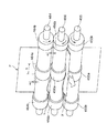
そのために、第1〜第3折りローラ455、456、464は、図6に示すようにローラの軸方向に大径部を有しており、各ローラは、ローラ径の大きい領域(大径部)を、シート搬送中央部に大径部455a、456a、464aと、Z折り処理部400でZ折り可能なシートPの最大サイズより外側に位置するシート搬送両端部に大径部455b、456b、464bとの各ローラに計3箇所設けている。
【0123】
この構成によれば、ニップ部X、およびYでシートPを挟持する際、シートPと各折りローラとはシート搬送中央部の大径部455a、456a、464aにおいて接触し挟持搬送される。
【0124】
その結果、シートPと第1〜第3折りローラ455、456、464との接触面積を減らすことが可能となり、シートPの折り皺が発生する部位に前記ローラ両軸端方向からのシート折り圧に対する逃げ場が確保され、折り皺の発生を防止できる。
【0125】
なお、シートPの最大搬送サイズより外側に設けた大径部455b、456b、464b(両端部のローラ径の大きい領域)は、シートPの斜送、および斜行等を考慮しても、シートPが、大径部455b、456b、464bに掛からない位置に形成されている。
【0126】
仮にシートPが、大径部455b、456b、464b上に掛かるような配置とすると、シートPが斜送、および斜行することにより、シートPの折り皺の発生を招くことになる。
【0127】
そこで、シートPのニップ部X、Yで挟持搬送されるシートPにおける最大搬送サイズのローラ軸方向での可動範囲の幅をαとし、大径部455b同士、456b同士、464b同士間の配置距離をβとすると、α<βとなる。
【0128】
α<βの関係とすることにより、シートPが大径部455b、456b、464bに掛かることは回避され、上記の原因による折り皺の発生は防止される。
【0129】
また、α<βの関係とすることにより、シートPは大径部455b、456b、464bにガイドされる状態となり、横レジずれ等を起こすことによる搬送不良も防止できる。
【0130】
シート搬送中央部の大径部455a、456a、464aの軸方向の幅が、シートPの幅に比べて狭すぎると、折りが甘くなってしまい、折った紙がシート受け皿上で膨らんでしまい、積載すると不安定になる。
【0131】
そこで、大径部455a、456a、464a(シート搬送中央部のローラ径の大きい領域)の軸方向の幅hは、Z折り処理部400で、Z折り可能なシートサイズの最小(例えば、B4)サイズ幅(幅sとする)の約1/2になるように設定されている。つまり、h≒1/2sとして、安定してシート折りし、シートPを挟持搬送するための大径部455a、456a、464aの軸方向の幅は設定されている。
【0132】
また、第1〜第3折りローラ455、456、464上の軸方向の段差をδ、シートの厚さをtと場合、δ<3tの関係になるように大径部455a、456a、464aおよび455b、456b、464bを設けている。
【0133】
大径部455a、456a、464aの段差δを設けたことにより、シートPの折り皺が発生する部位に前記シート折り圧に対する逃げ場を確保する隙間を形成することができる。
【0134】
そして、大径部455b、456b、464bの段差δを設けたことにより、シートPのニップ部X、Yでの搬送の際、両端部の段差がシートPのガイドの役割を果たすため、横レジずれを防止し、安定した搬送を得るとともに、シートPが大径部455b、456b、464上に掛かり斜めに搬送されることもないので、シートPが斜送することによる折り皺も防止できる。
【0135】
折りローラ455、456、464の段付きにより形成されたローラ間の隙間bは、各折りローラ455、456、464が当接された際の圧力により圧縮されるため、ローラ間の隙間をbとした場合、隙間bと前記折りローラ(大径部)の段差δとの関係は、b<2δとなる。
【0136】
このとき、ローラ間の隙間bは、シートPの厚さをtとした場合、b<3tの関係になるよう圧接している。なお、折りローラ455、456、464は、イニシャル時やゴム硬度が高くニップが形成しない場合でも、b<3tの関係を満足するように設定されている。
【0137】
このような構成によればローラのシート搬送中央部でシートPを強力に安定して挟持搬送でき、折りローラ対の折り圧力が小さくなり折りが甘くなるようなこともない。それと同時に、ローラ間の隙間bを設けることにより、ニップ部X、YがシートPを密に挟持した際のシート両端方向からのシート折り圧に対するシートの圧力の逃げ場を確保でき、折り皺の発生防止に有効である。
【0138】
具体的には、シートPの厚みtを約0.1mmとした場合、ローラの軸方向の段差δを0.2mmとして、各ローラ対の圧接によるニップ形成で、ローラ間隙間bを0.3(3つ折りのため、3枚分)mm以下になるようにするのがよい。
【0139】
従って、以上のような折りローラであるため、シートPを折る際には、シートPのローラへの接触面積を減らすことができるため、折り皺の発生を防止できる。
【0140】
本実施の形態では第1および第2折りローラ455、456で形成されるローラ対と、第2および第3折りローラ456、464で形成されるローラ対の各々の折りローラに大径部を形成した構成としているが、ローラの段付きが形成されるのは、各ローラ対一方のみでもよい。
【0141】
つまり、少なくとも、第1および第2折りローラ455、456で形成されるローラ対か、第2および第3折りローラ456、464で形成されるローラ対か、の少なくとも一方でも段付きローラであればよい。
【0142】
なお、図3に示したような2つ折り処理部500における折りローラ対208に、本発明構成を用いてもよい。
【0143】
図7(c)は、図7(b)に図示されている本実施の形態に係るZ(3つ)折り処理部の他の構造例を示した図である。図7(c)において、856は第2折りローラ、864は第3折りローラ、856aおよび864aは折りローラ856および864各々のシート搬送中央部に形成された大径部(ローラ径の大きい領域)、856bおよび864bは折りローラ856および864各々のシート搬送両端部に形成された大径部(ローラ径の大きい領域)である。
【0144】
第2折りローラ856および864は、上記段付きローラの大径部856a、864a、856b、864bの両端に縮径するテーパを設けている。
【0145】
図7(b)および(c)を比較すると、図7(c)の大径部の端部がシートPと接する角度θは、θ>90°となるため、図7(b)の大径部の端部がシートPと接する角度90°に比べ鈍角となる。
【0146】
つまり、前記大径部に前記テーパを設けたため、大径部856a、864a、856b、464bの前記端部の角度は、大径部456a、464a、456b、464bの前記端部の角度に比べて緩やかになる。
【0147】
大径部が前記テーパ構造を採れば、シートPが折り処理のためニップ部に進入したとき、大径部856a、864a、856b、864b各々の前記端部はシートPと緩やかに接することとなる。そのため、シートPを折る際に発生する大径部による折り跡を軽減することができる。
【0148】
以上、本実施の形態では複写機を実施例として用いて説明したが、これは本発明を複写機に限定する趣旨ではなく、レーザプリンタ等の他の画像形成装置を用いても構わない。
【0149】
なお、画像形成手段としては、電子写真方式の画像形成手段以外にも、インクジェット式の画像形成手段や、熱転写記録方式や感熱記録方式等を適用しても構わない。
【0150】
【発明の効果】
本発明のシート折り装置は、折りローラ対の各ローラの軸方向に小径部と大径部とを有しており、前記大径部でシートを挟持搬送しているので、シートを折る際には、シートのローラへの接触面積を減らすことができるため、折り皺の発生を防止できる。
【0151】
また、ローラ径の大きい領域のシート搬送中央部の幅を、シート折り処理部で、シート折り可能なシートサイズの最小サイズ幅の約半分になるように設定されていることによって、シート搬送中央部で強力にシート折りが可能となり、折りが甘くなることがないので、折り処理後のシートのシート受け皿上での膨らみを防ぎ、積載の際の安定性を確保できる。
【0152】
さらに、シートの最大搬送サイズより外側に設けた大径部は、シートの横レジずれ等を考慮して、シートが、前記大径部に掛からない位置に設定されている。
【0153】
このことにより、シートが横レジずれ等を起こした場合に、ローラの搬送ニップに挟持されてしまうことによって起きる、折り皺の発生や搬送不良を防止できる。
【0154】
よって、前記シート折り装置におけて、安定した高精度なシート折り処理が可能となる。
【0155】
また、上記のシート折り装置をシート折り処理部に備えた画像形成装置としたことにより、折り皺を防止し、シート積載時の不安定や搬送不良等を引き起こすことの少ない、安定した高精度なシート折り処理行う画像形成装置を提供することができる。
【図面の簡単な説明】
【図1】本発明の実施形態に係る画像形成装置の実施例である複写機の概略正面断面図である。
【図2】本発明の実施形態に係る画像形成装置の実施例である複写機の制御ブロック図である。
【図3】2つ折り処理部とフィニッシャの概略正面図である。
【図4】 Z(3つ)折り処理部の動作説明用の概略正面断面図である。
(a)シートを2つに折る直前の状態を示した図である。
(b)シートの2つに折っている状態を示した図である。
【図5】 Z(3つ)折り処理部の動作説明用の概略正面断面図である。
(a)シートをZ(3つ)折りする直前の状態を示した図である。
(b)シートのZ(3つ)折りを開始する際の状態を示した図である。
(c)シートをZ(3つ)折りにして排出している状態を示した図である。
【図6】 Z(3つ)折り処理部の実施形態のローラの斜視図である。
【図7】 Z(3つ)折り処理部の動作説明用の概略正面断面図である。
(a)従来例のZ(3つ)折り処理部を示した図である。
(b)本発明の実施例のZ(3つ)折り処理部、およびZ(3つ)折り処理部の大径部がシートPと接した状態を示した図である。
(c)他の構造例のZ(3つ)折り処理部、およびZ(3つ)折り処理部の大径部がシートPと接した状態を示した図である。
【図8】 Z(3つ)折り処理部の制御ブロック図である。
【符号の説明】
56 第2折りローラ(従来例)
64 第3折りローラ(従来例)
100 原稿給送部
111 感光ドラム(画像形成手段)
114、115 カセット(シート積載手段)
118 排出ローラ対
200 イメージリーダ部
300 画像形成ユニット部
400 Z(3つ)折り処理部(実施例)
450 Z折り搬送路
451 フラッパ
452 受入搬送路
453 搬送ローラ対
454 シート先端受けストッパ
455 第1折りローラ
456 第2折りローラ
457 シート先端検知センサ
458 案内壁
459 開口部
460 Z折り制御部
461 シート折り端受けストッパ
462 シート折り端検知センサ
463 折りガイド
464 第3折りローラ
465 送り出し搬送路
466 排出ローラ対
467 補助搬送路
468 補助搬送ローラ対
469 第1折りパス
470 第2折りパス
455a、456a、464a 大径部(シート搬送中央部のローラ径の大きい領域)
455b、456b、464b 大径部(シート搬送両端部ローラ径の大きい領域)
500 2つ折り処理部
508 パンチユニット(シート孔開け装置)
600 フィニッシャ
700 スタックトレイ
701 サンプルトレイ
856 第2折りローラ(他の実施例)
864 第3折りローラ(他の実施例)
856a、864a 大径部(シート搬送中央部のローラ径の大きい領域)
856b、864b 大径部(シート搬送両端部ローラ径の大きい領域)
900 インサータ
1000 複写機(画像形成装置)
b ニップ形成によるローラ間の隙間
t シートの厚さ
X 第1、第2折りローラ455、456により形成されたニップ部
Y 第2、第3折りローラ456、464により形成されたニップ部
δ 第1〜3折りローラ(段付き部)の段差
θ 折りローラ856、864の大径部の端部がシートPと接する角度[0001]
BACKGROUND OF THE INVENTION
The present invention relates to a sheet folding apparatus that performs a folding process on a sheet, and an image forming apparatus including the sheet folding apparatus.
[0002]
[Prior art]
Conventionally, as this type of sheet folding apparatus, one that performs half-folding and Z-folding on a sheet such as paper is known.
[0003]
The half-folding is, for example, folding into two with a center position in the conveyance length direction of the sheet as a fold.
[0004]
On the other hand, Z-folding is performed by folding once a ¼ position in the conveyance length direction with respect to one end of the sheet as a fold, and further inverting the 1/4 position with respect to the other end of the sheet as a reference. It wraps around. As described above, in Z-folding, if the first and second times are folds at ¼ positions from the leading edge of the sheet, the folded sheet is exactly half the size of the original sheet material.
[0005]
This sheet folding apparatus is used in combination with, for example, a copying machine or a laser beam printer. A sheet on which an image is formed on the surface of a copying machine or the like is half-folded or Z-folded with the image surface facing inward. With such a configuration, it is not necessary to provide a time for folding after image formation, and folding is completed almost simultaneously with the end of image formation, which is efficient.
[0006]
[Problems to be solved by the invention]
However, in the case of the above prior art, the following problems have occurred.
[0007]
In such a conventional sheet folding apparatus, there has been a problem that creases occur in the sheet during the sheet folding process.
[0008]
FIG. 7A illustrates the configuration of a conventional folding processing unit. As a conventional measure for preventing creases, CR (neoprene) rubber having a hardness of 70 ° to 90 ° is used for the roller, and the diameters of the centers of the
[0009]
However, also in this case, since the contact area of the sheet P with the
[0010]
Further, the leading end portion of the sheet P or the loop-shaped folded portion is sandwiched obliquely with respect to the roller nip line due to skew or the like, or the roller nip line itself is bent due to variations in the nip pressure in the width direction of the
[0011]
On the other hand, it is conceivable to reduce the folding pressure of the pair of folding rollers so as not to cause creases. However, when the folding pressure is reduced, the folded paper becomes swollen due to the sweetness of the folding, and such a sheet is swelled. Since it becomes unstable when stacked on the sheet tray, the amount of sheets that can be stacked on the sheet tray is limited.
[0012]
As another countermeasure, the sheet is pressed between the rollers by lowering the friction coefficient of each roller of the pair of folding rollers by means such as application of silicon oil on the roller surface so that the entire width direction is in close contact with the rollers. It is possible to eliminate the occurrence of wrinkles after being pushed into the nip portion, but even in this case, it is very difficult to maintain a constant friction coefficient including the durability of each roller.
[0013]
The present invention has been made to solve the above-described problems, and its purpose is to prevent the above-described folding, and to prevent the occurrence of instability and poor conveyance during sheet stacking, and stable high accuracy. An object of the present invention is to provide a sheet folding apparatus having an appropriate sheet folding processing technique and an image forming apparatus including the sheet folding apparatus.
[0014]
[Means for Solving the Problems]
In order to achieve the above object, a sheet folding apparatus according to the present invention includes:Folding is performed while nipping and conveying the sheetFolding roller pairWithAt least one roller of the pair of folding rollers,Of the rollerAxial directionSingle alongLarge diameter andProvided on both sides of the large diameter partWith small diameter partThe small-diameter portion is provided corresponding to the sheet width in the axial direction of the folding roller pair of the sheet that can be folded.
[0015]
According to this configuration, when the sheet is sandwiched by the nip portion of the pair of folding rollers, the sheet and each folding roller are in contact with each other at the large diameter portion. As a result, it becomes possible to reduce the contact area between the sheet and each folding roller, thereby securing a escape area against the pressure from the two shaft end directions when the sheet is folded on the part where the sheet folding occurs. And the occurrence of creases can be prevented.
[0016]
The roller is provided with a large-diameter portion for nipping and conveying the sheet at the sheet conveyance central portion. (Corresponding to claim 2)
[0017]
By specifically setting the portion where the roller is in contact with the sheet at the sheet conveyance center portion of the roller, the contact area when the sheet is conveyed and clamped by the large-diameter portion is reduced, and there is an escape space in the sheet folding pressure. Secured and effective in preventing the occurrence of creases.
[0018]
The axial width of the large-diameter portion provided at the sheet conveyance central portion of the folding roller is approximately half the minimum size width of the sheet size that can be folded in the sheet folding apparatus. It is desirable to provide a large diameter portion at the center of the sheet conveyance. (Corresponding to claim 3)
[0019]
In the sheet conveyance center portion of the folding roller, the width of the large-diameter portion is set to be about half of the minimum size width of the sheet size that can be folded in the sheet folding apparatus, thereby the sheet conveyance A stable folding process is possible at the center. As a result, the folding does not become sweet, so that the bulging of the folded sheet on the sheet tray is prevented, and the stability when stacking sheets is obtained.
[0020]
The large-diameter portion of the roller is disposed so as to be located outside the movable range of the maximum size sheet in the apparatus. (Corresponding to claim 4)
[0021]
The large-diameter portion provided outside the maximum conveyance size of the sheet is set at a position where the sheet does not engage the large-diameter portion, so that the sheet is obliquely fed and skewed on the large-diameter portion. Can prevent the sheet from being folded.
[0022]
It is desirable that a predetermined gap be provided between the rollers in the conveying nip of the folding roller pair. (Corresponding to claim 5)
[0023]
Further, it is effective to set the predetermined gap between the rollers to be smaller than the thickness of three sheets conveyed to the nip. (Corresponding to claim 6)
[0024]
By providing a gap between the rollers, it is possible to secure a sheet escape area against the sheet folding pressure when the conveyance nip portion tightly clamps the sheet, which is effective in preventing the occurrence of creases.
[0025]
In the sheet folding apparatus, the large diameter portion of the roller may have a taper. (Corresponding to claim 7)
[0026]
By forming the taper at the end of the large-diameter portion formed at both ends and the center of the folding roller, the end can more gently contact the sheet. As a result, it is possible to reduce fold marks when the sheet is folded at the nip portion.
[0027]
Also provided is an image forming unit that forms an image on a sheet, a sheet conveying unit that conveys a sheet on which an image is formed by the image forming unit, and a sheet folding processing unit that folds the conveyed sheet. In the image forming apparatus,
The sheet folding device according to any one of claims 1 to 7 is provided as the sheet folding processing means. (Corresponding to claim 8)
[0028]
In addition to the electrophotographic image forming means, an inkjet image forming means, a thermal transfer recording method, a thermal recording method, or the like can be applied as the image forming means.
[0029]
DETAILED DESCRIPTION OF THE INVENTION
Exemplary embodiments of the present invention will be described in detail below with reference to the drawings. However, the dimensions, materials, shapes, relative arrangements, and the like of the components described in this embodiment are not intended to limit the scope of the present invention only to those unless otherwise specified. Absent.
[0030]
Further, in the following drawings, the same reference numerals are given to members described in the drawings used in the description of the above-described prior art and members similar to the members described in the above-described drawings.
[0031]
Hereinafter, embodiments of the present invention will be described with reference to the drawings.
[0032]
(Copier 1000)
FIG. 1 is a schematic front sectional view showing an internal structure of a copying
[0033]
Examples of the sheet include plain paper, a thin resin sheet postcard which is a substitute for plain paper, a cardboard, a sealed letter, and a plastic thin plate.
[0034]
(Control system)
FIG. 2 is a control block diagram of the copying
[0035]
Then, the document
[0036]
The
[0037]
The
[0038]
Also, an image of the original read by the
[0039]
The image forming
[0040]
(
On the
[0041]
Documents set on the
[0042]
At this time, the
[0043]
When the document passes over the
[0044]
On the other hand, a document read process can be performed by temporarily stopping the document conveyed by the
[0045]
Further, when reading a document without using the
[0046]
(Image forming unit 300)
The document image data read by the
[0047]
The electrostatic latent image formed on the photosensitive drum 111 is developed by the developing
[0048]
The visualized toner image is transferred to the sheet in the
[0049]
Then, the
[0050]
As a result, the surface on which the toner image is formed can be discharged from the
[0051]
As described above, when the sheet is discharged from the
[0052]
When image forming processing is performed on a hard sheet such as an OHP sheet conveyed from the manual
[0053]
When image forming processing is performed on both sides of the sheet, the sheet is guided straight from the fixing
[0054]
However, when the sheet is reversed and discharged, the sheet may be curled while being switched back by the
[0055]
In such a case, the sheet that passes through the Z-
[0056]
Therefore, the sheet reaching the pair of
[0057]
In order to discharge the sheet at a higher speed than when the reverse discharge is not performed, the
[0058]
Incidentally, the sheet discharge speed when the sheet is not reversed is about 350 mm / s, but the sheet discharge speed when the sheet is reversed is about 450 mm / s.
[0059]
In the copying machine described above, the sheet curls in a U-shape, but when the sheet curls in an inverted U-shape (in this case, referred to as “lower curl”), the sheet jam is prevented in the same manner. it can.
[0060]
In some copiers, when the sheet curls up or down due to heat and is reversed, the sheet curls in the opposite direction to the curl and cancels the curl.
[0061]
In this case, since the sheet discharged without inversion is curled, the sheet is jammed by increasing the sheet discharge speed when discharging the sheet without inversion more than the sheet conveyance speed when discharging the sheet with inversion. Can be prevented.
[0062]
Also, the sheet may curl when the sheet passes through a Z-
[0063]
(Folding processing unit 500)
The
[0064]
The sheet that has passed through the Z-
[0065]
The sheets conveyed by the
[0066]
Further, two pairs of
[0067]
A
[0068]
When the sheet bundle bound by the
[0069]
Note that, similarly to the
[0070]
An
[0071]
The control of the
[0072]
(Inserter 900)
In FIG. 3, an
[0073]
The sheet bundle stacked on the
[0074]
A
[0075]
Further, the
[0076]
The
[0077]
(Finisher 600)
In FIG. 3, the
[0078]
As shown in FIG. 3, the
[0079]
The sheet guided to the finisher path 504 is conveyed toward the
[0080]
A
[0081]
The
[0082]
A switching
[0083]
The switching
[0084]
The sheet guided to the non-sort path 521 by the switching
[0085]
On the other hand, the switching
[0086]
The sheets guided to the
[0087]
The stapling process is performed by the
[0088]
When the sheet bundle is discharged from the
[0089]
(Z-fold processing unit 400)
Next, a detailed description will be given of the Z-
[0090]
When an A3 size sheet or a B4 size sheet is designated by the operation unit 303 (see FIG. 2) and the Z-folding process is specified, the Z-folding process is performed on the sheet discharged from the
[0091]
On the other hand, in other cases, the sheet discharged from the
[0092]
The Z-
[0093]
At this time, if the sheet P hits the sheet leading
[0094]
Therefore, in order to prevent the conveyed sheet P from jumping on the sheet leading
[0095]
As a result, the sheet P gently lands on the sheet leading
[0096]
Thereafter, the
[0097]
When the sheet P approaches the nip portion X, the Z-folding control unit 460 (see FIG. 2) stops the conveyance motor M21 for the second time, and the second time after the vibration of the loop-shaped portion of the sheet P is settled. Let's start. For this reason, the loop-shaped portion of the sheet P is fed into the nip portion X in a stable state.
[0098]
The second stop timing of the conveyance motor M21 is detected by the sheet leading
[0099]
In the present embodiment, when the sheet P approaches the sheet leading
[0100]
The sheet P is decelerated or temporarily stopped immediately before coming into contact with the sheet leading
[0101]
Thereafter, as shown in FIG. 4B, the first and
[0102]
In the
[0103]
As a result, the folding end of the sheet P is gently brought into contact with the sheet folding
[0104]
The folding drive motor M22 rotates the three
[0105]
Then, as shown in FIG. 5A, after the folded end of the sheet P comes into contact with the sheet folded
[0106]
In the present embodiment, when the sheet P approaches the sheet folding
[0107]
Thereafter, as shown in FIG. 5 (b), the sheet P starts buckling at the portion of the sheet P facing the lower end of the
[0108]
The Z-
[0109]
That is, the
[0110]
When the looped portion of the sheet P approaches the nip portion Y of the second and third
[0111]
The fourth rotation stop of the folding drive motor M22 is performed after a predetermined time has elapsed since the folding drive motor M22 started the third start.
[0112]
After the lapse of a predetermined time after the fold driving motor M22 has stopped rotating for the fourth time for a predetermined time, the fold driving motor M22 starts for the fourth time and folds the loop-shaped portion of the sheet P in the second and third folds. The
[0113]
As a result, the sheet P is accurately folded in three without causing wrinkles and discharged from the second and third
[0114]
Thereafter, the sheet P is sent to the
[0115]
The above operation is automatically performed by the
[0116]
In the present embodiment, the folding drive motor M22 is stopped and started four times in the above-described operation of the
[0117]
Further, the folding
[0118]
That is, when the folding drive motor M22 is stopped for the third and fourth times, after the sheet P comes into contact with the sheet leading
[0119]
Further, as shown in FIG. 1, the Z-
[0120]
Next, in the conventional example, since the contact area of the sheet P with the
[0121]
Therefore, in the Z-
[0122]
For this purpose, the first to
[0123]
According to this configuration, when the sheet P is sandwiched between the nip portions X and Y, the sheet P and each folding roller are brought into contact with each other at the large-
[0124]
As a result, the contact area between the sheet P and the first to
[0125]
Note that the
[0126]
If the sheet P is arranged so as to hang over the
[0127]
Therefore, the width of the movable range in the roller axis direction of the maximum conveyance size in the sheet P that is nipped and conveyed by the nip portions X and Y of the sheet P is α, and the arrangement distance between the
[0128]
By satisfying the relationship of α <β, the sheet P is prevented from being caught on the
[0129]
Further, by satisfying α <β, the sheet P is guided to the
[0130]
If the axial width of the large-
[0131]
Therefore, the axial width h of the large-
[0132]
Further, when the step in the axial direction on the first to
[0133]
By providing the step δ of the
[0134]
Since the step δ of the
[0135]
The gap b between the rollers formed by the stepping of the
[0136]
At this time, the gap b between the rollers is in pressure contact so that the relationship of b <3t is satisfied when the thickness of the sheet P is t. The
[0137]
According to such a configuration, the sheet P can be strongly and stably nipped and conveyed at the sheet conveyance central portion of the roller, and the folding pressure of the pair of folding rollers is reduced and the folding is not sweetened. At the same time, by providing a gap b between the rollers, the nip portion X, Y can secure a escape area of the sheet pressure against the sheet folding pressure from both ends of the sheet when the sheet P is tightly sandwiched, and generation of creases It is effective for prevention.
[0138]
Specifically, when the thickness t of the sheet P is about 0.1 mm, the step δ in the axial direction of the roller is set to 0.2 mm, and the gap b between the rollers is set to 0.3 by forming a nip by pressure contact of each roller pair. It is better to make it equal to or less than 3 mm (for 3 sheets because of three folds).
[0139]
Therefore, since the folding roller as described above is used, when the sheet P is folded, the contact area of the sheet P with the roller can be reduced, so that the occurrence of creases can be prevented.
[0140]
In this embodiment, a large-diameter portion is formed on each folding roller of the roller pair formed by the first and
[0141]
That is, at least one of the pair of rollers formed by the first and
[0142]
Note that the configuration of the present invention may be used for the
[0143]
FIG. 7C is a diagram showing another example of the structure of the Z (three) folding processing unit according to the present embodiment shown in FIG. 7B. In FIG. 7C,
[0144]
The
[0145]
Comparing FIGS. 7B and 7C, the angle θ at which the end of the large-diameter portion in FIG. 7C contacts the sheet P is θ> 90 °, so the large diameter in FIG. The obtuse angle becomes smaller than the angle 90 ° at which the end of the portion contacts the sheet P.
[0146]
That is, since the taper is provided in the large diameter portion, the angle of the end portions of the
[0147]
If the large diameter portion adopts the taper structure, when the sheet P enters the nip portion for folding, the end portions of the large diameter portions 856a, 864a, 856b, and 864b come into gentle contact with the sheet P. . Therefore, it is possible to reduce the fold caused by the large diameter portion that occurs when the sheet P is folded.
[0148]
Although the present embodiment has been described using the copying machine as an example, this is not intended to limit the present invention to the copying machine, and other image forming apparatuses such as a laser printer may be used.
[0149]
As the image forming means, in addition to the electrophotographic image forming means, an ink jet image forming means, a thermal transfer recording method, a thermal recording method, or the like may be applied.
[0150]
【The invention's effect】
The sheet folding apparatus of the present invention has a small diameter portion and a large diameter portion in the axial direction of each roller of the pair of folding rollers, and sandwiches and conveys the sheet by the large diameter portion. Since the contact area of the sheet to the roller can be reduced, the occurrence of creases can be prevented.
[0151]
In addition, the width of the sheet conveyance central portion in the region with a large roller diameter is set to be about half of the minimum size width of the sheet size that can be folded at the sheet folding processing portion, so that the sheet conveyance central portion Since the sheet can be folded strongly and the folding does not become sweet, it is possible to prevent the folded sheet from being swollen on the sheet tray and to ensure the stability during stacking.
[0152]
Further, the large-diameter portion provided outside the maximum conveyance size of the sheet is set at a position where the sheet does not hang over the large-diameter portion in consideration of a lateral registration shift of the sheet.
[0153]
As a result, when the sheet is laterally misaligned, it is possible to prevent the occurrence of creases and poor conveyance that are caused by being nipped by the conveyance nip of the roller.
[0154]
Therefore, stable and highly accurate sheet folding processing can be performed in the sheet folding apparatus.
[0155]
In addition, the above-described sheet folding apparatus is an image forming apparatus provided in the sheet folding processing unit, so that folding is prevented and stable and highly accurate with less instability and poor conveyance during sheet stacking. An image forming apparatus that performs sheet folding processing can be provided.
[Brief description of the drawings]
FIG. 1 is a schematic front sectional view of a copying machine as an example of an image forming apparatus according to an embodiment of the present invention.
FIG. 2 is a control block diagram of a copier that is an example of an image forming apparatus according to an exemplary embodiment of the present invention.
FIG. 3 is a schematic front view of a two-fold processing unit and a finisher.
FIG. 4 is a schematic front sectional view for explaining the operation of a Z (three) fold processing section.
(A) It is the figure which showed the state just before folding a sheet into two.
(B) It is the figure which showed the state folded into two of the sheet | seat.
FIG. 5 is a schematic front sectional view for explaining the operation of a Z (three) fold processing section;
(A) It is the figure which showed the state just before folding a sheet | seat (Z).
(B) It is the figure which showed the state at the time of starting Z (three) folding of a sheet | seat.
(C) It is the figure which showed the state discharged | emitted after folding a sheet into Z (three).
FIG. 6 is a perspective view of a roller of an embodiment of a Z (three) fold processing unit.
FIG. 7 is a schematic front sectional view for explaining the operation of a Z (three) fold processing section.
(A) It is the figure which showed the Z (three) folding process part of the prior art example.
(B) It is the figure which showed the state which the large diameter part of the Z (three) fold processing part and the Z (three) fold processing part of the Example of this invention contact | connected the sheet | seat P.
(C) is a diagram showing a state where the Z (three) fold processing portion of another structural example and the large diameter portion of the Z (three) fold processing portion are in contact with the sheet P.
FIG. 8 is a control block diagram of a Z (three) folding processing unit.
[Explanation of symbols]
56 Second folding roller (conventional example)
64 Third folding roller (conventional example)
100 Document feeder
111 Photosensitive drum (image forming means)
114, 115 cassette (sheet stacking means)
118 discharge roller pair
200 Image reader
300 Image forming unit
400 Z (three) folding processing unit (Example)
450 Z-fold conveyance path
451 Flapper
452 Acceptance conveyance path
453 Pair of transport rollers
454 Sheet end stopper
455 First folding roller
456 Second folding roller
457 Sheet tip detection sensor
458 guide wall
459 opening
460 Z-fold control unit
461 Sheet folding edge receiving stopper
462 Sheet folded edge detection sensor
463 folding guide
464 Third Folding Roller
465 Delivery path
466 discharge roller pair
467 Auxiliary conveyance path
468 Auxiliary transport roller pair
469 First Fold Path
470 Second folding path
455a, 456a, 464a Large-diameter portion (region where the roller diameter is large in the central portion of the sheet conveyance)
455b, 456b, 464b Large diameter part (area where the roller diameter at both ends of the sheet conveyance is large)
500 Folding processing part
508 Punch unit (sheet punching device)
600 Finisher
700 stack tray
701 Sample tray
856 Second Folding Roller (Other Examples)
864 Third folding roller (another embodiment)
856a, 864a Large diameter part (area where the roller diameter is large in the central part of the sheet conveyance)
856b, 864b Large diameter part (area where the roller diameter is large at both ends of the sheet conveyance)
900 Inserter
1000 Copying machine (image forming device)
b Gap between rollers due to nip formation
t Sheet thickness
X Nip formed by the first and
Y Nip formed by the second and third
δ Step of first to third folding rollers (stepped portion)
θ The angle at which the ends of the large diameter portions of the
Claims (8)
ことを特徴とするシート折り装置。A pair of folding rollers for performing a folding process while nipping and conveying the sheet, and at least one roller of the pair of folding rollers is provided on a single large-diameter portion and on both sides of the large-diameter portion along the axial direction of the rollers. It was possess a small diameter portion, the small diameter portion is a sheet folding apparatus characterized by provided corresponding to the sheet width in the axial direction of the pair of folding rollers of the folding processable sheet.
前記画像形成手段によって画像が形成されたシートを搬送するシート搬送手段と、
前記シート搬送手段により搬送されるシートに折り加工を施す請求項1乃至7のいずれか1項記載のシート折り装置とを備えた
ことを特徴とする画像形成装置。Image forming means for forming an image on a sheet;
Sheet conveying means for conveying a sheet on which an image is formed by the image forming means;
An image forming apparatus comprising: the sheet folding device according to claim 1, which performs a folding process on the sheet conveyed by the sheet conveying unit.
Priority Applications (5)
| Application Number | Priority Date | Filing Date | Title |
|---|---|---|---|
| JP2000400377A JP3817424B2 (en) | 2000-12-28 | 2000-12-28 | Sheet folding apparatus and image forming apparatus provided with the same |
| US10/021,088 US20020086786A1 (en) | 2000-12-28 | 2001-12-19 | Sheet folding apparatus and image forming apparatus having the same |
| EP01130933A EP1225147B1 (en) | 2000-12-28 | 2001-12-27 | Sheet folding apparatus and image forming apparatus having the same |
| DE60135968T DE60135968D1 (en) | 2000-12-28 | 2001-12-27 | Folding device for sheets and image forming apparatus with this device |
| CNB011440856A CN1188752C (en) | 2000-12-28 | 2001-12-28 | Sheet folding apparatus and imaging equipment with said sheet folding apparatus |
Applications Claiming Priority (1)
| Application Number | Priority Date | Filing Date | Title |
|---|---|---|---|
| JP2000400377A JP3817424B2 (en) | 2000-12-28 | 2000-12-28 | Sheet folding apparatus and image forming apparatus provided with the same |
Publications (3)
| Publication Number | Publication Date |
|---|---|
| JP2002193544A JP2002193544A (en) | 2002-07-10 |
| JP2002193544A5 JP2002193544A5 (en) | 2004-07-22 |
| JP3817424B2 true JP3817424B2 (en) | 2006-09-06 |
Family
ID=18864984
Family Applications (1)
| Application Number | Title | Priority Date | Filing Date |
|---|---|---|---|
| JP2000400377A Expired - Lifetime JP3817424B2 (en) | 2000-12-28 | 2000-12-28 | Sheet folding apparatus and image forming apparatus provided with the same |
Country Status (5)
| Country | Link |
|---|---|
| US (1) | US20020086786A1 (en) |
| EP (1) | EP1225147B1 (en) |
| JP (1) | JP3817424B2 (en) |
| CN (1) | CN1188752C (en) |
| DE (1) | DE60135968D1 (en) |
Families Citing this family (16)
| Publication number | Priority date | Publication date | Assignee | Title |
|---|---|---|---|---|
| WO2001042239A1 (en) † | 1999-12-13 | 2001-06-14 | Sumika Fine Chemicals Co., Ltd. | Process for the preparation of a pyridinemethanol compound |
| US20020168250A1 (en) * | 2001-05-10 | 2002-11-14 | Welch Stephen R. | Method and apparatus for forming a binder cover and ring binder |
| JP3715919B2 (en) | 2001-12-21 | 2005-11-16 | キヤノン株式会社 | Image reading apparatus and image forming apparatus |
| JP4235543B2 (en) * | 2003-12-16 | 2009-03-11 | キヤノン株式会社 | Image reading apparatus and image forming apparatus having the same |
| US20060180970A1 (en) * | 2004-09-13 | 2006-08-17 | Nisca Corporation | Sheet finishing apparatus and image forming apparatus equipped with the same |
| US8667392B2 (en) | 2006-12-12 | 2014-03-04 | Xerox Corporation | Automated submission of folded print job |
| JP4721463B2 (en) * | 2007-02-02 | 2011-07-13 | キヤノン株式会社 | Sheet processing apparatus and image forming apparatus having the same |
| US8590880B2 (en) * | 2009-10-30 | 2013-11-26 | Nisca Corporation | Sheet folding apparatus and image formation system provided with the apparatus |
| US8585032B2 (en) * | 2009-10-30 | 2013-11-19 | Nisca Corporation | Sheet folding apparatus and image formation system provided with the apparatus |
| JP5024424B2 (en) | 2010-05-11 | 2012-09-12 | コニカミノルタビジネステクノロジーズ株式会社 | Paper folding device and paper post-processing device using the same |
| JP5024425B2 (en) * | 2010-05-11 | 2012-09-12 | コニカミノルタビジネステクノロジーズ株式会社 | Paper folding device and paper post-processing device using the same |
| JP5024423B2 (en) * | 2010-05-11 | 2012-09-12 | コニカミノルタビジネステクノロジーズ株式会社 | Paper folding device and paper post-processing device using the same |
| EP2708484B1 (en) * | 2012-09-18 | 2015-02-11 | Ricoh Company Ltd. | Sheet processing apparatus, image forming system, and method of enhancing folding of sheet bundle |
| JP6231860B2 (en) | 2013-11-19 | 2017-11-15 | 理想科学工業株式会社 | Paper folding device |
| JP6708810B2 (en) * | 2014-05-20 | 2020-06-10 | 株式会社リコー | Sheet processing device, image forming system |
| JP6758857B2 (en) * | 2016-02-25 | 2020-09-23 | キヤノン株式会社 | Sheet transfer device and image forming device |
Family Cites Families (5)
| Publication number | Priority date | Publication date | Assignee | Title |
|---|---|---|---|---|
| CH454180A (en) * | 1967-05-26 | 1968-04-15 | Ferag Ag | Device for pressing flexible sheet-like structures produced in a continuous flow |
| US3796423A (en) * | 1972-09-05 | 1974-03-12 | Rockwell International Corp | Buckle folder fold roller |
| US3796361A (en) * | 1972-12-26 | 1974-03-12 | A Rueckert | Folding roller for use in a buckle folding machine |
| US5114395A (en) * | 1990-03-23 | 1992-05-19 | Martin Yale Industries, Inc. | Paper sheet folding device |
| US5180151A (en) * | 1991-12-30 | 1993-01-19 | Pitney Bowes Inc. | Grooved paper folding rollers |
-
2000
- 2000-12-28 JP JP2000400377A patent/JP3817424B2/en not_active Expired - Lifetime
-
2001
- 2001-12-19 US US10/021,088 patent/US20020086786A1/en not_active Abandoned
- 2001-12-27 EP EP01130933A patent/EP1225147B1/en not_active Expired - Lifetime
- 2001-12-27 DE DE60135968T patent/DE60135968D1/en not_active Expired - Lifetime
- 2001-12-28 CN CNB011440856A patent/CN1188752C/en not_active Expired - Fee Related
Also Published As
| Publication number | Publication date |
|---|---|
| CN1362646A (en) | 2002-08-07 |
| CN1188752C (en) | 2005-02-09 |
| EP1225147A3 (en) | 2004-01-07 |
| EP1225147B1 (en) | 2008-10-01 |
| DE60135968D1 (en) | 2008-11-13 |
| EP1225147A2 (en) | 2002-07-24 |
| US20020086786A1 (en) | 2002-07-04 |
| JP2002193544A (en) | 2002-07-10 |
Similar Documents
| Publication | Publication Date | Title |
|---|---|---|
| US7489898B2 (en) | Sheet processing apparatus and image forming apparatus provided with the same | |
| US7681872B2 (en) | Sheet processing apparatus and image forming apparatus | |
| JP3817424B2 (en) | Sheet folding apparatus and image forming apparatus provided with the same | |
| JP5825564B2 (en) | Sheet processing apparatus and image forming system | |
| US9381658B2 (en) | Sheet processing apparatus and image forming apparatus | |
| US7922165B2 (en) | Sheet stacking apparatus, sheet processing apparatus and image forming apparatus | |
| US8702086B2 (en) | Sheet post-processing apparatus and image forming apparatus | |
| JP5528099B2 (en) | Sheet post-processing apparatus and image forming apparatus having the same | |
| JP4541938B2 (en) | Sheet processing apparatus and image forming apparatus | |
| JP2007269488A (en) | Sheet handling device and image forming device | |
| JP2006193288A (en) | Sheet processing device and image forming device having the same | |
| JP4722643B2 (en) | Sheet processing apparatus and image forming apparatus | |
| JP4871750B2 (en) | Sheet processing apparatus and image forming apparatus | |
| JP4377830B2 (en) | Paper folding device | |
| JP5219642B2 (en) | Sheet processing apparatus and image forming apparatus | |
| JP2009132533A (en) | Medium processing apparatus and medium processing method | |
| JP2000044115A (en) | Paper folding device | |
| JP5268582B2 (en) | Sheet stacking apparatus and image forming apparatus | |
| US20080185764A1 (en) | Sheet processing apparatus | |
| JP4764504B2 (en) | Sheet processing apparatus and image forming apparatus provided with the apparatus | |
| JP3791348B2 (en) | Paper folding apparatus and image forming apparatus | |
| JP3958043B2 (en) | Sheet material post-processing apparatus and method | |
| JP3991774B2 (en) | Folding method and post-processing apparatus | |
| JP2007131436A (en) | Sheet handling device and image forming device equipped with it | |
| JP2021098559A (en) | Sheet folding device |
Legal Events
| Date | Code | Title | Description |
|---|---|---|---|
| A977 | Report on retrieval |
Free format text: JAPANESE INTERMEDIATE CODE: A971007 Effective date: 20050629 |
|
| A131 | Notification of reasons for refusal |
Free format text: JAPANESE INTERMEDIATE CODE: A131 Effective date: 20050726 |
|
| A521 | Request for written amendment filed |
Free format text: JAPANESE INTERMEDIATE CODE: A523 Effective date: 20050926 |
|
| TRDD | Decision of grant or rejection written | ||
| A01 | Written decision to grant a patent or to grant a registration (utility model) |
Free format text: JAPANESE INTERMEDIATE CODE: A01 Effective date: 20060606 |
|
| A61 | First payment of annual fees (during grant procedure) |
Free format text: JAPANESE INTERMEDIATE CODE: A61 Effective date: 20060612 |
|
| R150 | Certificate of patent or registration of utility model |
Free format text: JAPANESE INTERMEDIATE CODE: R150 Ref document number: 3817424 Country of ref document: JP Free format text: JAPANESE INTERMEDIATE CODE: R150 |
|
| FPAY | Renewal fee payment (event date is renewal date of database) |
Free format text: PAYMENT UNTIL: 20090616 Year of fee payment: 3 |
|
| FPAY | Renewal fee payment (event date is renewal date of database) |
Free format text: PAYMENT UNTIL: 20100616 Year of fee payment: 4 |
|
| FPAY | Renewal fee payment (event date is renewal date of database) |
Free format text: PAYMENT UNTIL: 20110616 Year of fee payment: 5 |
|
| FPAY | Renewal fee payment (event date is renewal date of database) |
Free format text: PAYMENT UNTIL: 20120616 Year of fee payment: 6 |
|
| FPAY | Renewal fee payment (event date is renewal date of database) |
Free format text: PAYMENT UNTIL: 20120616 Year of fee payment: 6 |
|
| FPAY | Renewal fee payment (event date is renewal date of database) |
Free format text: PAYMENT UNTIL: 20130616 Year of fee payment: 7 |
|
| EXPY | Cancellation because of completion of term |