JP3815585B2 - Magnetic resonance imaging system - Google Patents
Magnetic resonance imaging system Download PDFInfo
- Publication number
- JP3815585B2 JP3815585B2 JP28494597A JP28494597A JP3815585B2 JP 3815585 B2 JP3815585 B2 JP 3815585B2 JP 28494597 A JP28494597 A JP 28494597A JP 28494597 A JP28494597 A JP 28494597A JP 3815585 B2 JP3815585 B2 JP 3815585B2
- Authority
- JP
- Japan
- Prior art keywords
- echo
- image
- echo signal
- navigation
- magnetic resonance
- Prior art date
- Legal status (The legal status is an assumption and is not a legal conclusion. Google has not performed a legal analysis and makes no representation as to the accuracy of the status listed.)
- Expired - Fee Related
Links
- 238000002595 magnetic resonance imaging Methods 0.000 title claims description 28
- 230000033001 locomotion Effects 0.000 claims description 34
- 238000012937 correction Methods 0.000 claims description 18
- 238000002592 echocardiography Methods 0.000 claims description 12
- 238000001514 detection method Methods 0.000 claims description 8
- 230000001678 irradiating effect Effects 0.000 claims description 7
- 230000003068 static effect Effects 0.000 claims description 5
- 238000000034 method Methods 0.000 description 47
- 238000005259 measurement Methods 0.000 description 36
- 238000003384 imaging method Methods 0.000 description 24
- 238000002594 fluoroscopy Methods 0.000 description 13
- 238000010586 diagram Methods 0.000 description 10
- 230000010363 phase shift Effects 0.000 description 7
- 238000001208 nuclear magnetic resonance pulse sequence Methods 0.000 description 5
- 230000002123 temporal effect Effects 0.000 description 3
- 238000005481 NMR spectroscopy Methods 0.000 description 2
- 230000005540 biological transmission Effects 0.000 description 2
- 238000013480 data collection Methods 0.000 description 2
- 238000009792 diffusion process Methods 0.000 description 2
- 238000012545 processing Methods 0.000 description 2
- 239000000523 sample Substances 0.000 description 2
- 238000012935 Averaging Methods 0.000 description 1
- UFHFLCQGNIYNRP-UHFFFAOYSA-N Hydrogen Chemical compound [H][H] UFHFLCQGNIYNRP-UHFFFAOYSA-N 0.000 description 1
- OAICVXFJPJFONN-UHFFFAOYSA-N Phosphorus Chemical compound [P] OAICVXFJPJFONN-UHFFFAOYSA-N 0.000 description 1
- 230000015572 biosynthetic process Effects 0.000 description 1
- 238000000701 chemical imaging Methods 0.000 description 1
- 229940079593 drug Drugs 0.000 description 1
- 239000003814 drug Substances 0.000 description 1
- 230000000694 effects Effects 0.000 description 1
- 238000001914 filtration Methods 0.000 description 1
- 229910052739 hydrogen Inorganic materials 0.000 description 1
- 239000001257 hydrogen Substances 0.000 description 1
- 238000000691 measurement method Methods 0.000 description 1
- 238000012986 modification Methods 0.000 description 1
- 230000004048 modification Effects 0.000 description 1
- 229910052698 phosphorus Inorganic materials 0.000 description 1
- 239000011574 phosphorus Substances 0.000 description 1
- 230000001131 transforming effect Effects 0.000 description 1
Images


Classifications
-
- G—PHYSICS
- G01—MEASURING; TESTING
- G01R—MEASURING ELECTRIC VARIABLES; MEASURING MAGNETIC VARIABLES
- G01R33/00—Arrangements or instruments for measuring magnetic variables
- G01R33/20—Arrangements or instruments for measuring magnetic variables involving magnetic resonance
- G01R33/44—Arrangements or instruments for measuring magnetic variables involving magnetic resonance using nuclear magnetic resonance [NMR]
- G01R33/48—NMR imaging systems
- G01R33/54—Signal processing systems, e.g. using pulse sequences ; Generation or control of pulse sequences; Operator console
- G01R33/56—Image enhancement or correction, e.g. subtraction or averaging techniques, e.g. improvement of signal-to-noise ratio and resolution
- G01R33/565—Correction of image distortions, e.g. due to magnetic field inhomogeneities
- G01R33/56554—Correction of image distortions, e.g. due to magnetic field inhomogeneities caused by acquiring plural, differently encoded echo signals after one RF excitation, e.g. correction for readout gradients of alternating polarity in EPI
-
- G—PHYSICS
- G01—MEASURING; TESTING
- G01R—MEASURING ELECTRIC VARIABLES; MEASURING MAGNETIC VARIABLES
- G01R33/00—Arrangements or instruments for measuring magnetic variables
- G01R33/20—Arrangements or instruments for measuring magnetic variables involving magnetic resonance
- G01R33/44—Arrangements or instruments for measuring magnetic variables involving magnetic resonance using nuclear magnetic resonance [NMR]
- G01R33/48—NMR imaging systems
- G01R33/54—Signal processing systems, e.g. using pulse sequences ; Generation or control of pulse sequences; Operator console
- G01R33/56—Image enhancement or correction, e.g. subtraction or averaging techniques, e.g. improvement of signal-to-noise ratio and resolution
- G01R33/565—Correction of image distortions, e.g. due to magnetic field inhomogeneities
- G01R33/56509—Correction of image distortions, e.g. due to magnetic field inhomogeneities due to motion, displacement or flow, e.g. gradient moment nulling
Landscapes
- Physics & Mathematics (AREA)
- Health & Medical Sciences (AREA)
- General Health & Medical Sciences (AREA)
- Nuclear Medicine, Radiotherapy & Molecular Imaging (AREA)
- Radiology & Medical Imaging (AREA)
- Engineering & Computer Science (AREA)
- Signal Processing (AREA)
- High Energy & Nuclear Physics (AREA)
- Condensed Matter Physics & Semiconductors (AREA)
- General Physics & Mathematics (AREA)
- Magnetic Resonance Imaging Apparatus (AREA)
Description
【0001】
【発明の属する技術分野】
本発明は、被検体中の水素や燐等からの核磁気共鳴(以下、NMRという)信号を測定し、核の密度分布や緩和時間分布等を映像化する磁気共鳴撮影(MRI)装置におけるイメージング方法(以下、MRI方法という)に関し、特に動画像における高い時間分解能を保持しつつ体動アーチファクトをなくしたMRI方法に関する。
【0002】
【従来の技術】
マルチショットエコープラーナーイメージング(マルチショットEPI)や3次元EPI等において、ショット間で被検体が動くことにより画像に生じる体動アーチファクトを低減させるためのナビゲーションエコー法が知られている(Seong-Gi Kim ら「ナビゲータを持つ高速インターリーブEPI:4テスラにおける高分解能の解剖学的及び機能的イメージ」マグネティックレゾナンスインメディスン 35:895-902、June 1996)。
【0003】
ナビゲーションエコーは、例えば図4に示すマルチショットEPIシーケンスにおいてRFパルス201と一連のエコー取得ルーチン211との間で、ナビゲーションエコー発生用傾斜磁場パルスを印加することにより発生させる。このようなシーケンスを図5に示す。図示するようにナビゲーションエコーは各RF照射毎に1個以上入っている。繰り返し時間210内での被検体の位置ゆらぎはないものとし、1の繰り返し時間内で取得されたナビゲーションエコーと他の繰り返し時間内で取得されたナビゲーションエコーとの変化から、被検体の動きを推定する。
【0004】
例えば図6に示すように、1枚の画像を得るために1個のナビゲーションエコーを含む繰り返し単位304の計測を4回繰り返す場合(305)、ショット番号1番の最初の計測(図中灰色で示す)のナビゲーションエコーを基準として、それ以降の3回の計測(ショット番号2〜4)のナビゲーションエコーの変化から対応する本計測データ(図5の207)について所定の体動補正を行い1枚の画像601を得る。
【0005】
一方、動画像のMR画像にマルチショットEPIを適用するものとして、MRフロロスコピーが知られている。これは図7に示すように、計測開始から計測終了まで随時繰り返し単位209の計測を行い続けながらエコー信号を取得し、最後に行った計測から新しい順に、画像一枚を再構成するのに必要な数のエコー信号、例えば図7では4回分の計測で得られたエコー信号を用いて、各時間での画像を再構成するものである。
【0006】
このようなMRフロロスコピーによってもショット間の体動によるアーチファクトの問題は生じるが、MRフロロスコピーにナビゲーションエコー法を適用したものはなかった。
【0007】
【発明が解決しようとする課題】
上記のMRフロロスコピーにナビゲーションエコー法を組合せて体動補正することが考えられるが、単純に組み合わせた場合には、図8に示すように、1計測304ずつ順次ずらして画像501を構成していく際に各画像で位相補正の基準となるナビゲーションエコーは、4回の繰り返し単位のショット番号のうち固定的なショット番号のもの、例えば1番(図中灰色で示す)のナビゲーションエコーとなる。
【0008】
この場合、画像501は計測304の繰り返し時間TR毎に更新されるが、基準となるナビゲーションエコーは最初の計測304から4回目毎に更新されて行くので(更新時は図中灰色で示す、A、B、C)、ナビゲーションエコーを用いた体動補正の基準時刻は4TR間隔に延びることとなる。
【0009】
しかし、実用的には体動補正の基準時間を極力細かく設定することが時間分解能向上の上で強く望まれている。
【0010】
そこで本発明は、動画像における高い時間分解能を保持したうえで、体動補正を行なうことができるMRI方法を実現するMRI装置を提供することを目的とする。
【0011】
【課題を解決するための手段】
本発明のMRI装置では、被検体に磁気共鳴周波数のRFパルスを照射後、エコー信号を時系列的に検出するシーケンスと、得られたエコー信号を用いて画像を再構成するステップとを連続して繰り返し、画像再構成に用いるエコー信号の一部を順次更新して動画像を得るMRI装置において、RFパルス照射毎にナビゲーションエコーを発生させると共にこれを検出し、画像毎に、画像再構成に用いるエコー信号を位相するための基準となるナビゲーションエコーを準じ更新して前記エコー信号を位相補正し、画像を得るものである。
【0012】
基準となるナビゲーションエコーを順次更新していくことにより、体動補正の基準時刻を画像の更新間隔と一致させることができ、高い時間分解能を有して体動補正を行うことができる。
【0013】
このようなMRI方法は、複数回のRFパルスの照射を繰り返すことにより取得したエコー信号から画像データを得る場合、即ちマルチショットシーケンスにおいて好適に適用することができ、ショット間に生じた体動によるアーチファクトをなくすことができる。
【0014】
ナビゲーションエコーは、好適には、各RFパルスに対して少なくとも1つの位相エンコード量0のナビゲーションエコーを付加的に発生させる。体動補正は、基準となるナビゲーションエコーと、各RFパルスで取得したナビゲーションエコーとの位相差を用い、取得したエコー信号の位相を補正するにより、体動アーチファクトをほぼ完全に取り除くことができる。
【0015】
【発明の実施の形態】
以下、本発明のMRI方法を図面を参照して説明する。
【0016】
図3は、本発明が適用される典型的なMRI装置の概略構成を示す図で、このMRI装置は、被検体401の周囲に静磁場を発生する磁石402と、該空間に傾斜磁場を発生する傾斜磁場コイル403と、この領域に高周波磁場を発生するRFコイル404と、被検体401が発生するMR信号を検出するRFプローブ405とを備えている。ベッド412は被検体が横たわるためのものである。
【0017】
傾斜磁場コイル403は、直交する3軸方向の傾斜磁場コイルで構成され、傾斜磁場電源409からの信号に応じてそれぞれ傾斜磁場を発生する。これら3軸方向の傾斜磁場コイルにより、スライス方向、位相エンコード方向及び読み出し方向からなる3軸方向の傾斜磁場を被検体の置かれた空間に印加することができる。尚、傾斜磁場の印加軸は必ずしも傾斜磁場コイルのxyz軸と一致する必要はない。
【0018】
RFコイル404はRF送信部410の信号に応じて高周波磁場をパルスとして発生する。RFプローブ405の信号は、信号検出部406で検出され、信号処理部407で信号処理され、また計算により画像信号に変換される。画像は表示部408で表示される。傾斜磁場電源409、RF送信部410、信号検出部406は制御部411で制御され、制御のタイムチャートは一般にパルスシーケンスと呼ばれており、本発明では動画像形成のためのパルスシーケンスが実行される。
【0019】
次に、本発明のMRI方法で採用するMRフロロスコピーについて図1を用いて説明する。動画像を得るには時間的に連続して撮像を繰り返す必要があり、全撮像時間103内に複数回(P回)の撮像1021、1022、1023・・・・を行う。1回の撮像はそれぞれ図5に示すようなマルチショットシーケンスからなり、この例ではショット数4のマルチショットEPIが採用されており、各撮像内は4回の計測1011〜1014がなされる。図ではこれに1〜4のショット番号を付している。4回の計測において取得されたエコー信号により1枚の画像が再構成される。
【0020】
1枚目の画像1041は、撮像1021で取得されたショット番号1〜4の組に含まれるエコーを用いて作成される。2枚目の画像1042は、最初の撮像1021におけるショット番号1のエコー信号を、次の撮像1022におけるショット番号1で取得されたエコー信号で更新したエコー信号の組を用いて作成する。同様に、3枚目の画像1043は、最初の撮像1021におけるショット番号2のエコー信号を、次の撮像1022におけるショット番号2のエコー信号で更新したエコー信号の組を用いて作成する。以降同様に、最先ショットで得られたエコー信号を新しく撮像された同一ショット番号のエコー信号と更新することにより、エコートレイン群の一部を順次更新しながら画像を作成する。これにより、計測の繰り返し時間TRの間隔で動画像を得ることができる。
【0021】
このように得られる動画像はショット間に体動があると、それがアーチファクトとなるため、本発明のイメージング方法では各計測1011〜1014毎にナビゲーションエコーを発生、検出するステップを導入し、これらナビゲーションエコーにより画像再構成に用いるエコー信号を位相補正を行う。
【0022】
ナビゲーションエコーを発生させるパルスシーケンスは、マルチショットシーケンスにナビゲーションエコーを発生させる手順を加えたもので、図5に示すようにまずスライス傾斜磁場Gs202と同時にRFパルス2011が照射され、次いでナビゲーションエコー発生のための傾斜磁場Gr301が印加される。この傾斜磁場301の正負の印加量が等しくなったところでエコー3021が発生し、これを時間範囲303の間サンプリングし時系列データを得る。このナビゲーションエコーには位相エンコード傾斜磁場が印加されておらず、位相エンコード量0である。
【0023】
図5において点線で囲った部分2111、2112は図4に示すマルチショットEPIシーケンスの手順211に対応し、ここではオフセット読み出し傾斜磁場205と位相エンコード量にオフセットを与えるための傾斜磁場Gp203が与えられ、続いて連続して反転する読み出し傾斜磁場Gr206とこれに同期して位相エンコード傾斜磁場Gp204が印加される。反転する読み出し傾斜磁場Gr206の各周期内で各位相エンコードのエコー信号207が時系列的に発生するので、これを時間範囲208の間おのおのサンプリングし時系列データを得る。
【0024】
RFパルス照射から手順2111までを位相エンコード傾斜磁場Gp203のオフセット量を変えながら、全位相エンコード量のエコー信号を計測するまで繰り返し時間TR304で繰り返す。例えば位相エンコード方向のエンコード量(KY)を256、1回のRFパルス照射で計測されるエコー信号の数(エコートレイン数M)を64とすると、シーケンスのショット数N(繰り返し数)が4のマルチショットEPIとなる。この場合、読み出し方向のデータ数(KX)は256とする。
【0025】
このパルスシーケンスを図1のMRフロロスコピーに適用した場合、ショット数N(=4)×撮像回数Pに対応する数のナビゲーションエコーが得られる。各ナビゲーションエコーはV(kx,pn)で表すことができる。ここでkxは読み出し方向のデータ番号で1≦kx≦KXを満たす。pnはp番目の撮像のn番目のショットにおいて取得されたナビゲーションエコーであることを表し、1≦p≦P、1≦n≦Nを満たす。同様にp番目の撮像におけるn番目のショットにおいてm番目(1≦m≦M)に取得されたエコー信号Sは、S(kx,pn,m)で表すことができ、対応するナビゲーションエコーV(kx,pn)(pnが同じであるエコー)の位相情報に基づき体動補正される。
【0026】
次にこのようにして得られたナビゲーションエコーを用いた体動補正の方法、即ち各エコー信号S(kx,pn,m)の位相を補正する手順について説明する。
【0027】
本発明のMRI方法では、各ナビゲーションエコーの位相情報を得るための基準となるナビゲーションエコーは特定のショット番号のものに固定されず、順送りにしていく点を大きな特徴としている。即ち、各ショットのナビゲーションエコーは、ある時は体動モニターとしてのナビゲーションエコーであるが、ある時は基準ナビゲーションエコーになる。図1においては各ショットの上半部を灰色、下半部を白色で表示することにより、各ナビゲーションエコーが基準ともなり、モニターともなることを示す。
【0028】
本実施例では、画像取得時の被検体位置を反映させるため、画像再構成に用いる計測の組の中で時間的に一番古い(最先の)ショットにおけるナビゲーションエコーを基準ナビゲーションエコーに用いる場合を説明する。この場合には、1枚目の画像1041の基準ナビゲーションエコーはV(kx,11)(p=1,n=1)であり、これに基き計測1012〜1014で得られたエコーの体動補正がなされ、また2枚目の画像1042の基準ナビゲーションエコーはV(kx,12)(p=1,n=2)である。このように基準ナビゲーションエコーを順次更新していくことにより、体動補正の基準時刻をTR毎に更新することができ、時間分解能が向上する。
【0029】
体動補正の方法としていくつかの方法を採用することができるが、ここでは基準ナビゲーションエコーと、体動モニターとしての各ナビゲーションエコーとの位相差を直接求め、この位相差により対応するエコー信号の位相を補正する方法を説明する。
【0030】
今、基準ナビゲーションエコーをV(kx,1)、基準ナビゲーションエコーによって位相差を求めるべき各ナビゲーションエコーをV(kx,n)とすると、その位相差Pは、例えば次のような演算によって求められる。尚、V(kx,1)とV(kx,n)の撮像番号pは必ずしも一致しているとは限らないが、ここでは撮像番号に対応する符号は説明を簡単にするため省略する。
【0031】
まず、下記の演算により信号の実部と虚部のC(kx,n)を求める。
【0032】
【数1】

このC(kx,n)を位相シフトマップと名付ける。nについての位相差Pは、C(kx,n)を用いて、下式、
P(kx,n)≡arctan(im[C(kx,n)]/re[C(kx,n)])
により求めることができる。位相差Pは、読み出し方向のデータ番号(kx;時相)毎に求められる。
【0033】
この位相差から信号Sの位相差を補正するのであるが、上記演算によって求められた位相差は主値を回っている位相変化やノイズを含んでいる。従って、エコー信号S(kx,n,m)の位相補正に用いるに先立って、位相変化やノイズを補正する処理を行うことが好ましい。
【0034】
まず主値を回っている位相を除去するため、
|P(kx,n)−P(kx-1,n)|>A且つ|P(kx,n)−P(kx+1,n)|>A(Aは定数)
のときに、
P(kx,n)=(P(kx-1,n)+P(kx+1,n))/2
とする処理を行う。
【0035】
こうして主値回りを除去した後の位相はノイズが減少しているが、なお位相シフト量の算出の妨げとなり得るノイズ成分が含まれている。これらノイズ成分は、例えばメディアンフィルタ、バターワースフィルタ、局所平均化処理のようなフィルタ処理により抑制することができ、これにより全体的な位相シフトの変化が得られる。
【0036】
さらにフィルタ処理後の位相をより理想的な位相回りに近づけるため、全時相(-kx〜+kx)または一部分の時相について、例えばy=ax+b(a,bは定数)であるような1次関数に、関数フィッティングする。
【0037】
このように補正された位相シフトマップC'(kx,n)を用いて、エコー信号S(kx,n,m)を補正し、位相シフトを補正した信号S'(kx,n,m)を得る。位相シフトの補正は、位相シフトマップC'(kx,n)とkx及びnが同一であるエコー信号S(kx,n,m)について次式の演算により行う。
【0038】
【数2】
【0039】
このような体動補正処理を画像毎に基準となるナビゲーションエコーを更新しながら画像を再構成する。
【0040】
尚、以上の実施例では、基準となるナビゲーションエコーとして、エコートレイン群の中で最も早いナビゲーションエコーを用いた場合を説明したが、1枚の画像を構成する4つ計測のうちいずれの計測で取得されたナビゲーションエコーを基準としてもよい。
【0041】
また、上記実施例では位相補正方法として、ナビゲーションエコーのk空間データを用いて位相差を求め、信号をk空間で位相補正する方法を説明したが、本発明に適用できるナビゲーションエコーを用いた補正の方法はこれに限定されるわけではなく、ナビゲーションエコーをフーリエ変換した後の信号から位相差を求める公知の体動補正方法も採用できる。例えば、ナビゲーションエコーをフーリエ変換し、フーリエ変換された信号について、異なるナビゲーションエコー間の位相差を求め、ナビゲーションエコーと同じ軸にフーリエ変換された信号に対し、ナビゲーションエコーに対応する信号の位相を実空間上で補正する方法であってもよい。この方法はフーリエ変換を行う回数が多いため時間は要するが、細かい動きを精度よく補正することができるため、拡散イメージングのようなわずかな動きでもアーチファクトが現れるシーケンスに特に有効である。
【0042】
また、ナビゲーションエコーをフーリエ変換してプロファイルを求め、フーリエ変換後の異なるナビゲーションエコー間のプロファイルの位置ずれからナビゲーションエコーの位相差を相関関係により求め、対応する信号の位相をk空間上で補正する方法を採用することもできる。
【0043】
また、本発明に適用できるMRフロロスコピーの方法は上記実施例で説明したものに限定されず、種々の変更が可能である。例えば、MRフロロスコピーの方法として特開平6−343621号に記載された方法を採用することもできる。この方法では、1枚の画像を構成する複数計測のエコーのうち、特定の位相情報をもつ計測エコー(例えば低空間周波数領域のデータ)のみが画像毎に完全に入れ替わるように計測順序を制御する。
【0044】
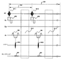
図2はこのような計測方法を示す図で、例えばk空間を3つの領域21、22、23に分けて撮像する場合、領域22の計測を他の領域の計測より多く繰り返し、順次更新される画像51、52、53では領域22については常に新しい計測データに置き換わるようにする。即ち、まず領域21、領域22、領域23のデータを順次収集して画像51を再構成し、次のデータ収集では新たに領域22及び21を順に取得し、直前の画像再構成に用いた領域23のデータと共に画像52を再構成する。さらに次のデータ収集では新たに領域22及び23を順に取得し、直前の画像再構成に用いた領域21のデータと共に画像53を再構成する。この場合、時間経過に伴う画像変化に最も寄与するのは低空間周波数領域であるため、この低空間周波数領域を常に更新される領域22とすることにより、再生画像の時間分解能をほとんど劣化させることなく動画を得ることができる。
【0045】
このような改良されたMRフロロスコピーにおいても、各計測にナビゲーションエコーの発生と検出を追加し、画像毎に例えば最先の計測で得られたナビゲーションエコーを基準として他の領域の計測データの位相を補正する。即ち画像51では領域21の計測で得られたナビゲーションエコーを基準として他の領域の計測データの位相を補正し、画像52では領域23の計測で得られたナビゲーションエコーを基準として他の領域の計測データの位相を補正する。この場合にも、画像の時間分解能2TRに合わせて位相補正の分解能も2TRとすることができる。基準とするナビゲーションエコーは、上述のように1つの画像について最先の計測で得られたナビゲーションエコーとしてもよいが、それに限定されず、例えば常に更新される領域22の計測で得られたナビゲーションエコーとしてもよい。
【0046】
また、一般にMR撮影の計測では本計測に先立って静磁場均一性を調整するため等のプリスキャンを行う場合があるので、このような場合にはプリスキャン自体にもナビゲーションエコーを加えることができ、このナビゲーションエコーを基準ナビゲーションエコーとしてもよい。
【0047】
さらに、本実施例では、MRフロロスコピーの基準シーケンスとしてEPIシーケンスを例にとって説明したが、このようなシーケンスに限定されるものではなく、原理的には、エコー信号を得る際にRFパルスのショットを繰り返して1枚の画像再構成のためのエコー信号を得るようなシーケンスに対しては、どのようなものであっても好適に適用できる。このようなシーケンスとして、例えば、バーストイメージング、ハイブリッドバーストイメージング、グラディエントエコーシーケンス、分割高速グラディエントエコーシーケンス、3d−EPI、エコーボリューマー、スパイラルイメージング、EPI型スペクトロスコピックイメージング、拡散イメージング等が挙げられる。
【0048】
また、本実施例では、ナビゲーションエコーをRFパルス1ショットにつき読み出し方向のみに1エコーづつ入れたが、読み出し方向、位相エンコード方向の2方向に入れてもよい。またナビゲーションエコーとしては、1軸方向のナビゲーションエコーに限らず、2つの直交する方向に位相が90度ずれた傾斜磁場を印加することにより発生させたオービタルナビゲーションエコーを採用することもできる。これにより、2つの軸により形成される平面の位相情報を補正することができる。
【0049】
また、本実施例では、ナビゲーションエコーは位相エンコード量0としているが、一般的にはナビゲーションエコーにおける位相エンコード量が同条件ならば0に限られるものではない。
【0050】
さらに、本発明は、以上の実施例で開示された内容にとどまらず、本発明の趣旨を踏まえた上で各種形態を取り得る。
【0051】
【発明の効果】
以上説明したように本発明によれば、MRフロロスコピーにナビゲーションエコー法を適用する際、基準となるナビゲーションエコーを動画を構成する画像ごとに順次更新していくことにより、動画像のMRI方法において、高い時間分解能を保持しつつ、また、画像取得時の被検体の位置情報を反映しつつ被検体の体動を補正することができる。
【図面の簡単な説明】
【図1】本発明のMRI方法の一実施例を説明する図。
【図2】本発明のMRI方法が適用される他の実施例を説明する図。
【図3】本発明のMRI方法を実施するためのMRI装置のブロック図。
【図4】本発明及び従来のMRI方法に適用されるマルチショットEPIのパルスシーケンス図。
【図5】本発明及び従来のMRI方法に適用されるナビゲーションエコー法を説明する図。
【図6】従来のナビゲーションエコー法を説明する図。
【図7】従来のMRフロロスコピーを説明する図。
【図8】MRフロロスコピーとナビゲーションエコー法とを単純に組み合わせた場合を説明する図。
【符号の説明】
304、1011〜1014・・・・・・繰り返し単位(計測)
1041〜1045・・・・・・画像
2011、2012・・・・・・RFパルス
3021、3022・・・・・・ナビゲーションエコー[0001]
BACKGROUND OF THE INVENTION
The present invention, imaging in nuclear magnetic resonance (hereinafter, NMR hereinafter) measures the signal, a magnetic resonance imaging to image density distribution and relaxation time distribution or the like of the nuclear (MRI) apparatus from hydrogen or phosphorus in the subject The present invention relates to a method (hereinafter referred to as an MRI method), and more particularly to an MRI method that eliminates body motion artifacts while maintaining high temporal resolution in moving images.
[0002]
[Prior art]
In multi-shot echo planar imaging (multi-shot EPI), three-dimensional EPI, etc., a navigation echo method is known for reducing body motion artifacts caused by movement of a subject between shots (Seong-Gi Kim et al. “High-speed interleaved EPI with navigator: high-resolution anatomical and functional image in 4 Tesla” Magnetic Resonance in Medicine 35: 895-902, June 1996).
[0003]
The navigation echo is generated, for example, by applying a navigation echo generation gradient magnetic field pulse between the
[0004]
For example, as shown in FIG. 6, when the measurement of the
[0005]
On the other hand, MR fluoroscopy is known as a technique for applying multi-shot EPI to MR images of moving images. As shown in FIG. 7, this is necessary to obtain an echo signal while repeating measurement of
[0006]
Although such an MR fluoroscopy also causes a problem of artifacts due to body movement between shots, there has been no application of the navigation echo method to MR fluoroscopy.
[0007]
[Problems to be solved by the invention]
It is conceivable to correct the body motion by combining the above-mentioned MR fluoroscopy with the navigation echo method. However, in the case of simple combination, as shown in FIG. The navigation echo that becomes a reference for phase correction in each image is the navigation echo of the fixed shot number among the shot numbers of the four repetition units, for example, No. 1 (shown in gray in the figure).
[0008]
In this case, the
[0009]
However, in practice, it is strongly desired to set the reference time for body motion correction as finely as possible to improve time resolution.
[0010]
Accordingly, an object of the present invention is to provide an MRI apparatus that realizes an MRI method capable of performing body motion correction while maintaining high time resolution in a moving image.
[0011]
[Means for Solving the Problems]
In the MRI apparatus of the present invention, after irradiating a subject with RF pulses having a magnetic resonance frequency, a sequence for detecting echo signals in time series and a step for reconstructing an image using the obtained echo signals are continuously performed. In an MRI apparatus that obtains a moving image by sequentially updating a part of echo signals used for image reconstruction, a navigation echo is generated and detected for each RF pulse irradiation, and image reconstruction is performed for each image. An image is obtained by updating the navigation echo as a reference for phasing the echo signal to be used and correcting the phase of the echo signal.
[0012]
By sequentially updating the reference navigation echo, the reference time for body motion correction can be made to coincide with the image update interval, and body motion correction can be performed with high time resolution.
[0013]
Such an MRI method can be suitably applied when image data is obtained from an echo signal acquired by repeating irradiation of a plurality of RF pulses, that is, in a multi-shot sequence, and is caused by body movement that occurs between shots. Artifacts can be eliminated.
[0014]
The navigation echo preferably additionally generates at least one phase encode amount zero navigation echo for each RF pulse. The body motion correction can remove the body motion artifact almost completely by correcting the phase of the acquired echo signal using the phase difference between the navigation echo as a reference and the navigation echo acquired by each RF pulse.
[0015]
DETAILED DESCRIPTION OF THE INVENTION
The MRI method of the present invention will be described below with reference to the drawings.
[0016]
FIG. 3 is a diagram showing a schematic configuration of a typical MRI apparatus to which the present invention is applied. This MRI apparatus generates a magnetic field around a
[0017]
The gradient
[0018]
The
[0019]
Next, MR fluoroscopy employed in the MRI method of the present invention will be described with reference to FIG. In order to obtain a moving image, it is necessary to repeat imaging continuously in time, and a plurality of (P) imagings 1021, 1022, 1023,... Each imaging is made up of a multi-shot sequence as shown in FIG. 5, and in this example, a multi-shot EPI with four shots is employed, and four
[0020]
The
[0021]
If there is a body movement between shots in the moving image obtained in this way, it becomes an artifact, so the imaging method of the present invention introduces a step of generating and detecting navigation echoes for each
[0022]
The pulse sequence for generating the navigation echo is a multi-shot sequence plus a procedure for generating the navigation echo. First, as shown in FIG. 5, the
[0023]
In FIG. 5,
[0024]
The process from RF pulse irradiation to
[0025]
When this pulse sequence is applied to the MR fluoroscopy in FIG. 1, navigation echoes of the number corresponding to the number of shots N (= 4) × number of imaging times P are obtained. Each navigation echo can be represented by V (kx, pn). Here, kx is a data number in the reading direction and satisfies 1 ≦ kx ≦ KX. pn represents the navigation echo acquired in the nth shot of the pth imaging, and satisfies 1 ≦ p ≦ P and 1 ≦ n ≦ N. Similarly, the echo signal S acquired in the mth (1 ≦ m ≦ M) in the nth shot in the pth imaging can be represented by S (kx, pn, m), and the corresponding navigation echo V ( The body motion is corrected based on the phase information of kx, pn) (echo with the same pn).
[0026]
Next, a method for correcting body motion using the navigation echo thus obtained, that is, a procedure for correcting the phase of each echo signal S (kx, pn, m) will be described.
[0027]
The MRI method of the present invention is characterized in that the navigation echo which is a reference for obtaining the phase information of each navigation echo is not fixed to a specific shot number but is forwarded. That is, the navigation echo of each shot is a navigation echo as a body movement monitor at one time, but becomes a reference navigation echo at another time. In FIG. 1, the upper half part of each shot is displayed in gray and the lower half part is displayed in white, which indicates that each navigation echo becomes both a reference and a monitor.
[0028]
In this embodiment, in order to reflect the subject position at the time of image acquisition, the navigation echo in the oldest (earliest) shot in the measurement group used for image reconstruction is used as the reference navigation echo. Will be explained. In this case, the reference navigation echo of the
[0029]
Several methods can be adopted as a method for correcting body motion. Here, the phase difference between the reference navigation echo and each navigation echo as a body motion monitor is directly obtained, and the phase difference of the corresponding echo signal is obtained by this phase difference. A method for correcting the phase will be described.
[0030]
Now, assuming that the reference navigation echo is V (kx, 1) and each navigation echo whose phase difference is to be obtained by the reference navigation echo is V (kx, n), the phase difference P is obtained, for example, by the following calculation. . Note that the imaging numbers p of V (kx, 1) and V (kx, n) are not necessarily the same, but here the reference numerals corresponding to the imaging numbers are omitted for the sake of simplicity.
[0031]
First, C (kx, n) of a real part and an imaginary part of a signal is obtained by the following calculation.
[0032]
[Expression 1]
This C (kx, n) is named a phase shift map. The phase difference P for n is expressed by the following equation using C (kx, n):
P (kx, n) ≡arctan (im [C (kx, n)] / re [C (kx, n)])
It can ask for. The phase difference P is obtained for each data number (kx: time phase) in the reading direction.
[0033]
The phase difference of the signal S is corrected from this phase difference. The phase difference obtained by the above calculation includes a phase change and noise around the main value. Therefore, it is preferable to perform a process for correcting a phase change and noise prior to use for phase correction of the echo signal S (kx, n, m).
[0034]
First, to remove the phase around the main value,
| P (kx, n) -P (kx-1, n) |> A and | P (kx, n) -P (kx + 1, n) |> A (A is a constant)
When
P (kx, n) = (P (kx-1, n) + P (kx + 1, n)) / 2
The process is performed.
[0035]
In this way, noise is reduced in the phase after the main value is removed, but still includes a noise component that can hinder the calculation of the phase shift amount. These noise components can be suppressed by a filter process such as a median filter, a Butterworth filter, or a local averaging process, thereby obtaining an overall phase shift change.
[0036]
Further, in order to bring the phase after filtering closer to the ideal phase, 1 for all time phases (−kx to + kx) or a part of time phases, for example, y = ax + b (a and b are constants). Function fitting to the next function.
[0037]
Using the phase shift map C ′ (kx, n) corrected in this way, the echo signal S (kx, n, m) is corrected, and the signal S ′ (kx, n, m) whose phase shift is corrected is obtained. obtain. The phase shift is corrected by calculating the following equation for the echo signal S (kx, n, m) having the same kx and n as the phase shift map C ′ (kx, n).
[0038]
[Expression 2]
[0039]
Such body motion correction processing reconstructs an image while updating a navigation echo as a reference for each image.
[0040]
In the above embodiment, the case where the earliest navigation echo in the echo train group is used as the reference navigation echo has been described, but any of the four measurements constituting one image may be used. The acquired navigation echo may be used as a reference.
[0041]
In the above embodiment, as the phase correction method, the method of obtaining the phase difference using the k-space data of the navigation echo and correcting the phase of the signal in the k-space has been described. However, the correction using the navigation echo applicable to the present invention is described. This method is not limited to this, and a well-known body motion correction method for obtaining a phase difference from a signal after Fourier transforming a navigation echo can also be adopted. For example, the navigation echo is Fourier-transformed, the phase difference between different navigation echoes is obtained for the Fourier-transformed signal, and the phase of the signal corresponding to the navigation echo is obtained for the signal Fourier-transformed on the same axis as the navigation echo. It may be a method of correcting in space. This method requires a lot of time because the number of times of Fourier transform is large, but fine motion can be corrected with high accuracy. Therefore, this method is particularly effective for a sequence in which artifacts appear even with slight motion such as diffusion imaging.
[0042]
Further, the navigation echo is subjected to Fourier transform to obtain a profile, the phase difference of the navigation echo is obtained from the positional deviation of the profile between different navigation echoes after the Fourier transform, and the phase of the corresponding signal is corrected in the k space. The method can also be adopted.
[0043]
The MR fluoroscopy method applicable to the present invention is not limited to that described in the above embodiment, and various modifications can be made. For example, the method described in Japanese Patent Laid-Open No. 6-343621 can be adopted as the MR fluoroscopy method. In this method, the measurement order is controlled so that only the measurement echo (for example, data in the low spatial frequency region) having specific phase information among the multiple measurement echoes constituting one image is completely replaced for each image. .
[0044]
FIG. 2 is a diagram showing such a measurement method. For example, when imaging is performed by dividing the k space into three
[0045]
Even in such improved MR fluoroscopy, the generation and detection of navigation echoes are added to each measurement, and the phase of the measurement data in other regions is taken for each image, for example, based on the navigation echo obtained in the earliest measurement. Correct. That is, in the
[0046]
In general, in MR imaging, pre-scanning such as adjusting the static magnetic field uniformity may be performed prior to the actual measurement. In such a case, navigation echo can be added to the pre-scan itself. This navigation echo may be used as a reference navigation echo.
[0047]
Furthermore, in this embodiment, the EPI sequence is described as an example of the MR fluoroscopy reference sequence. However, the present invention is not limited to such a sequence. In principle, when an echo signal is obtained, an RF pulse shot is obtained. Any sequence can be suitably applied to a sequence in which the echo signal for reconstructing one image is obtained by repeating the above. Examples of such sequences include burst imaging, hybrid burst imaging, gradient echo sequence, divided high-speed gradient echo sequence, 3d-EPI, echo volumer, spiral imaging, EPI-type spectroscopic imaging, diffusion imaging, and the like.
[0048]
In this embodiment, navigation echoes are put in one echo pulse only in the readout direction per one shot of the RF pulse, but may be put in two directions, ie, the readout direction and the phase encoding direction. The navigation echo is not limited to the uniaxial navigation echo but can be an orbital navigation echo generated by applying a gradient magnetic field whose phase is shifted by 90 degrees in two orthogonal directions. Thereby, the phase information of the plane formed by the two axes can be corrected.
[0049]
In this embodiment, the navigation echo has a phase encoding amount of 0. However, in general, the phase encoding amount in the navigation echo is not limited to 0 if the condition is the same.
[0050]
Furthermore, the present invention is not limited to the contents disclosed in the above embodiments, and can take various forms in consideration of the gist of the present invention.
[0051]
【The invention's effect】
As described above, according to the present invention, when the navigation echo method is applied to the MR fluoroscopy, the navigation echo as a reference is sequentially updated for each image constituting the moving image. The body movement of the subject can be corrected while maintaining high time resolution and reflecting the position information of the subject at the time of image acquisition.
[Brief description of the drawings]
FIG. 1 is a diagram for explaining an embodiment of an MRI method of the present invention.
FIG. 2 is a diagram for explaining another embodiment to which the MRI method of the present invention is applied.
FIG. 3 is a block diagram of an MRI apparatus for carrying out the MRI method of the present invention.
FIG. 4 is a pulse sequence diagram of multi-shot EPI applied to the present invention and a conventional MRI method.
FIG. 5 is a diagram for explaining a navigation echo method applied to the present invention and a conventional MRI method.
FIG. 6 is a diagram for explaining a conventional navigation echo method.
FIG. 7 is a diagram illustrating conventional MR fluoroscopy.
FIG. 8 is a diagram illustrating a case where MR fluoroscopy and navigation echo method are simply combined.
[Explanation of symbols]
304, 1011 ~ 1014 ・ ・ ・ ・ ・ ・ Repeating unit (measurement)
1041 ~ 1045 ・ ・ ・ ・ ・ ・ Image
2011, 2012 ・ ・ ・ ・ ・ ・ RF pulse
3021, 3022 ... Navigation echo
Claims (4)
前記制御手段は、前記2種類のエコー信号を検出するシーケンスを連続して繰り返し、画像再構成に用いる画像用エコー信号の少なくとも一部を順次更新して複数の体動補正された画像を得、その際、基準となるナビゲーションエコー信号を一つ選択し、選択された基準ナビゲーションエコー信号に対する他のナビゲーションエコー信号との差に基いて前記体動補正を行う磁気共鳴イメージング装置において、
前記基準ナビゲーションエコー信号を、前記シーケンスの繰り返しの進行とともに更新していくことを特徴とする磁気共鳴イメージング装置。An RF pulse irradiation means for irradiating a subject placed in a static magnetic field with an RF pulse having a magnetic resonance frequency; an echo signal for detecting an image echo signal generated from the subject and a navigation echo signal for body movement correction; Detection means, image reconstruction means for reconstructing an image whose body motion has been corrected using the obtained two types of echo signals, and control for controlling the RF irradiation means, echo signal detection means and image reconstruction means Means and
The control means continuously repeats the sequence of detecting the two types of echo signals, sequentially updates at least part of the image echo signals used for image reconstruction, and obtains a plurality of body motion corrected images, At that time, in the magnetic resonance imaging apparatus that selects one navigation echo signal as a reference and corrects the body motion based on the difference between the selected reference navigation echo signal and other navigation echo signals,
The magnetic resonance imaging apparatus, wherein the reference navigation echo signal is updated as the sequence is repeated.
前記制御手段は、前記RFパルス照射毎にナビゲーションエコーを発生させると共にこれを検出し、画像毎に、画像再構成に用いるエコー信号を位相するための基準となるナビゲーションエコーを順次更新して前記エコー信号を位相補正し、画像を得るように前記RFパルス照射手段、エコー信号検出手段及び画像再構成手段を制御することを特徴とする磁気共鳴イメージング装置。Using an RF pulse irradiating means for irradiating a subject placed in a static magnetic field with an RF pulse having a magnetic resonance frequency, an echo signal detecting means for detecting an echo signal generated from the subject, and the obtained echo signal An image reconstructing means for reconstructing an image; and a control means for controlling the RF pulse irradiating means, an echo signal detecting means, and an image reconstructing means. The sequence of detecting the signal in time series and the step of reconstructing the image using the obtained echo signal are continuously repeated, and a part of the echo signal used for the image reconstruction is sequentially updated to update the moving image. In a magnetic resonance imaging apparatus to obtain
The control means generates and detects a navigation echo for each irradiation of the RF pulse, and sequentially updates the navigation echo as a reference for phasing an echo signal used for image reconstruction for each image. A magnetic resonance imaging apparatus characterized by controlling the RF pulse irradiation means, the echo signal detection means and the image reconstruction means so as to obtain an image by correcting the phase of the signal.
前記RFパルス照射手段からのRFパルスの照射の各々に応答して前記被検体の所定のスライス面の所定領域から発生するエコー信号群及び少なくとも一つのナビゲーターエコーを取得するために前記被検体を囲む静磁場空間に傾斜磁場を印加する手段と、
前記傾斜磁場印加手段からの傾斜磁場の印加に応答して発生した各エコー信号群に属するエコー信号群とナビゲーターエコーとを検出する手段と、
前記エコー検出手段で取得した複数のエコー信号群を用いて所定のスライス面の画像を再構成する手段とを備えた磁気共鳴イメージング装置において、
前記画像再構成手段は、各画像再構成において、前記エコー検出手段から新たに取得した少なくとも一つのエコー信号群とそれ以前の画像を再構成するのに用いた複数のエコー信号群の一部を用いて前記所定のスライス面の結果画像を再構成し、画像再構成のそれぞれに用いた複数のエコー信号群の一つに属するナビゲーターエコーの一つを基準ナビゲーターエコーとし、当該基準ナビゲーターエコーとそれ以外のナビゲーターエコーとの位相差を決定し、画像再構成に用いられた複数のエコー信号群の位相を、前記決定された位相差に基き補正し、複数のエコー信号群の各々の位相補正に用いた基準ナビゲーターエコーを画像再構成毎に更新することを特徴とする磁気共鳴イメージング装置。Means for repeatedly irradiating a subject placed in a static magnetic field with RF pulses having a magnetic resonance frequency at predetermined intervals;
Surrounding the subject to acquire an echo signal group generated from a predetermined region of a predetermined slice surface of the subject and at least one navigator echo in response to each irradiation of the RF pulse from the RF pulse irradiating means Means for applying a gradient magnetic field to the static magnetic field space;
Means for detecting echo signals and navigator echoes belonging to each echo signal group generated in response to application of a gradient magnetic field from the gradient magnetic field application means;
In a magnetic resonance imaging apparatus comprising: means for reconstructing an image of a predetermined slice plane using a plurality of echo signal groups acquired by the echo detection means;
The image reconstruction means includes at least one echo signal group newly acquired from the echo detection means and a part of a plurality of echo signal groups used to reconstruct the previous image in each image reconstruction. The result image of the predetermined slice plane is used to reconstruct, and one of the navigator echoes belonging to one of a plurality of echo signal groups used for each of the image reconstruction is set as a reference navigator echo, and the reference navigator echo and The phase difference between the other navigator echoes is determined, and the phases of the plurality of echo signal groups used for the image reconstruction are corrected based on the determined phase differences, and each phase correction of the plurality of echo signal groups is performed. A magnetic resonance imaging apparatus that updates a used reference navigator echo for each image reconstruction.
Priority Applications (4)
| Application Number | Priority Date | Filing Date | Title |
|---|---|---|---|
| JP28494597A JP3815585B2 (en) | 1997-10-17 | 1997-10-17 | Magnetic resonance imaging system |
| EP98116655A EP0909958A3 (en) | 1997-10-17 | 1998-09-03 | Use of navigator echoes for the correction of motion artifacts in MRI |
| US09/149,121 US6118273A (en) | 1997-10-17 | 1998-09-09 | Magnetic resonance imaging method and device therefor |
| CN98124131.XA CN1231177C (en) | 1997-10-17 | 1998-10-16 | Magnetic resonance imaging method and device therefor |
Applications Claiming Priority (1)
| Application Number | Priority Date | Filing Date | Title |
|---|---|---|---|
| JP28494597A JP3815585B2 (en) | 1997-10-17 | 1997-10-17 | Magnetic resonance imaging system |
Related Child Applications (1)
| Application Number | Title | Priority Date | Filing Date |
|---|---|---|---|
| JP2006121685A Division JP4068114B2 (en) | 2006-04-26 | 2006-04-26 | Magnetic resonance imaging system |
Publications (2)
| Publication Number | Publication Date |
|---|---|
| JPH11113878A JPH11113878A (en) | 1999-04-27 |
| JP3815585B2 true JP3815585B2 (en) | 2006-08-30 |
Family
ID=17685110
Family Applications (1)
| Application Number | Title | Priority Date | Filing Date |
|---|---|---|---|
| JP28494597A Expired - Fee Related JP3815585B2 (en) | 1997-10-17 | 1997-10-17 | Magnetic resonance imaging system |
Country Status (4)
| Country | Link |
|---|---|
| US (1) | US6118273A (en) |
| EP (1) | EP0909958A3 (en) |
| JP (1) | JP3815585B2 (en) |
| CN (1) | CN1231177C (en) |
Families Citing this family (35)
| Publication number | Priority date | Publication date | Assignee | Title |
|---|---|---|---|---|
| JP4197059B2 (en) * | 1997-10-17 | 2008-12-17 | 株式会社日立メディコ | Nuclear magnetic resonance imaging system |
| JP2002530173A (en) * | 1998-11-25 | 2002-09-17 | コーニンクレッカ フィリップス エレクトロニクス エヌ ヴィ | Magnetic resonance method and apparatus |
| JP4138258B2 (en) * | 1999-05-26 | 2008-08-27 | 株式会社日立メディコ | Magnetic resonance imaging system |
| JP2001095775A (en) * | 1999-10-01 | 2001-04-10 | Hitachi Medical Corp | Nuclear magnetic resonance imaging apparatus and procedure |
| JP3454760B2 (en) * | 1999-10-22 | 2003-10-06 | ジーイー・メディカル・システムズ・グローバル・テクノロジー・カンパニー・エルエルシー | Phase distribution measuring method and apparatus, phase correcting method and apparatus, and magnetic resonance imaging apparatus |
| US6424153B1 (en) * | 1999-11-23 | 2002-07-23 | Koninklijke Philips Electronics, N.V. | On-the-fly removal of data inconsistency with k-space oversampling and demodulation in MRI acquisitions |
| DE10029585C2 (en) * | 2000-06-15 | 2002-04-18 | Siemens Ag | Method for operating a magnetic resonance device with detection of changes in position |
| DE10044424C2 (en) * | 2000-09-08 | 2002-12-05 | Siemens Ag | Method for operating a magnetic resonance tomography device, wherein a spatially resolved navigator rod is obtained for position monitoring of an object to be examined |
| DE10051594A1 (en) | 2000-10-18 | 2002-05-02 | Philips Corp Intellectual Pty | Phase correction method for real-time MR imaging |
| DE10056874C2 (en) * | 2000-11-16 | 2003-02-06 | Siemens Ag | Method for operating a magnetic resonance device in which changes in position are detected by means of orbital navigator echoes |
| DE10105388B4 (en) * | 2001-02-06 | 2007-05-24 | Siemens Ag | Method for adapting the spatial coding during operation of a magnetic resonance apparatus |
| JP3858194B2 (en) * | 2001-04-04 | 2006-12-13 | ジーイー・メディカル・システムズ・グローバル・テクノロジー・カンパニー・エルエルシー | MRI equipment |
| JP3878429B2 (en) * | 2001-04-05 | 2007-02-07 | ジーイー・メディカル・システムズ・グローバル・テクノロジー・カンパニー・エルエルシー | MRI equipment |
| US6518759B2 (en) | 2001-04-09 | 2003-02-11 | Mayo Foundation For Medical Education And Research | Motion correction of magnetic resonance images |
| US6771068B2 (en) * | 2001-05-10 | 2004-08-03 | General Hospital Corporation | System and method for providing real-time motion correction by utilizing navigators |
| JP4443079B2 (en) | 2001-09-13 | 2010-03-31 | 株式会社日立メディコ | Magnetic resonance imaging apparatus and RF receiving coil for magnetic resonance imaging apparatus |
| JP4141147B2 (en) * | 2002-02-01 | 2008-08-27 | 株式会社日立メディコ | Magnetic resonance imaging system |
| US7239138B2 (en) | 2002-10-11 | 2007-07-03 | Koninklijke Philips Electronics N.V. | Magnetic resonance method and device |
| DE10330926B4 (en) * | 2003-07-08 | 2008-11-27 | Siemens Ag | Method for the absolute correction of B0 field deviations in magnetic resonance tomography imaging |
| DE102004017852B4 (en) * | 2004-04-13 | 2008-11-27 | Siemens Ag | Motion-corrected multi-shot method for diffusion-weighted imaging in magnetic resonance imaging |
| CN100392424C (en) * | 2004-11-15 | 2008-06-04 | 华东师范大学 | Method for implementing echo data reconstitution in graphic pulse sequence compiler |
| EP1911400A4 (en) * | 2005-07-27 | 2011-05-04 | Hitachi Medical Corp | Magnetic resonance imaging device |
| US7358732B2 (en) * | 2005-10-24 | 2008-04-15 | The General Hospital Corporation | System, method, software arrangement and computer-accessible medium for providing real-time motion correction by utilizing clover leaf navigators |
| DE102006002982B4 (en) * | 2006-01-21 | 2009-10-29 | Bruker Biospin Mri Gmbh | Magnetic resonance i.e. nuclear magnetic resonance, image generating method for use in clinical applications, involves phase-correcting data of measurements based on motion conditions to keep positions of partial area in stationary state |
| DE102006017049B3 (en) * | 2006-04-11 | 2008-02-14 | Siemens Ag | Method of recording magnetic resonance image data and magnetic resonance device |
| CN101470178B (en) * | 2007-12-29 | 2013-06-05 | 西门子(中国)有限公司 | Method and apparatus for restraining residual motion artifact |
| DE102010001703B4 (en) * | 2010-02-09 | 2012-03-08 | Bruker Biospin Mri Gmbh | Compensation for MR measurements on moving objects by adjusting the measurement conditions |
| DE102011006230B4 (en) | 2011-03-28 | 2013-01-24 | Siemens Aktiengesellschaft | Pixel-wise correction of phase information in MR images using a navigator signal |
| EP2831611B1 (en) * | 2012-03-26 | 2020-08-12 | Koninklijke Philips N.V. | Through-plane navigator |
| DE102014210471B4 (en) * | 2014-06-03 | 2018-11-08 | Siemens Healthcare Gmbh | A method of performing a magnetic resonance examination with a prospective motion correction and magnetic resonance system therefor |
| JP2016198392A (en) * | 2015-04-13 | 2016-12-01 | 東芝メディカルシステムズ株式会社 | Magnetic resonance imaging apparatus |
| US10823806B2 (en) * | 2017-11-22 | 2020-11-03 | Siemens Healthcare Gmbh | Magnetic resonance imaging using dataset undersampling |
| US10809341B1 (en) * | 2019-04-19 | 2020-10-20 | Canon Medical Systems Corporation | Readout-segmented echo planar imaging with k-space averaging |
| CN113625209B (en) * | 2020-05-09 | 2024-02-27 | 上海联影医疗科技股份有限公司 | Method and device for determining frequency drift amount of magnetic resonance system and computer equipment |
| CN112014781B (en) * | 2020-09-02 | 2021-04-20 | 无锡鸣石峻致医疗科技有限公司 | Phase correction method and device for magnetic resonance echo signals, computer equipment and computer readable storage medium |
Family Cites Families (11)
| Publication number | Priority date | Publication date | Assignee | Title |
|---|---|---|---|---|
| US4684891A (en) * | 1985-07-31 | 1987-08-04 | The Regents Of The University Of California | Rapid magnetic resonance imaging using multiple phase encoded spin echoes in each of plural measurement cycles |
| JPH0632643B2 (en) * | 1986-04-11 | 1994-05-02 | 株式会社日立メディコ | Nuclear magnetic resonance imaging device |
| US4830012A (en) * | 1987-08-14 | 1989-05-16 | Duke University | High speed NMR imaging method and apparatus |
| US5270654A (en) * | 1991-07-05 | 1993-12-14 | Feinberg David A | Ultra-fast multi-section MRI using gradient and spin echo (grase) imaging |
| JPH05154130A (en) * | 1991-12-06 | 1993-06-22 | Hitachi Ltd | Body motion artifact eliminating method |
| JP3283632B2 (en) * | 1993-06-04 | 2002-05-20 | 株式会社日立製作所 | Nuclear magnetic resonance equipment |
| JPH0775627A (en) * | 1993-06-11 | 1995-03-20 | Hitachi Ltd | Body motion follow-up measuring method in magnetic resonance diagnostic device |
| JP2713160B2 (en) * | 1994-03-31 | 1998-02-16 | 株式会社島津製作所 | MR imaging device |
| US5800354A (en) * | 1994-11-23 | 1998-09-01 | U.S. Phillips Corporation | Method of and device for magnetic resonance imaging |
| US5539312A (en) * | 1995-02-02 | 1996-07-23 | Mayo Foundation For Medical Education And Research | Detection and measurement of motion during NMR imaging using orbital navigator echo signals |
| DE19524184B4 (en) * | 1995-07-03 | 2006-08-17 | Siemens Ag | Pulse sequence for rapid imaging in magnetic resonance imaging |
-
1997
- 1997-10-17 JP JP28494597A patent/JP3815585B2/en not_active Expired - Fee Related
-
1998
- 1998-09-03 EP EP98116655A patent/EP0909958A3/en not_active Ceased
- 1998-09-09 US US09/149,121 patent/US6118273A/en not_active Expired - Lifetime
- 1998-10-16 CN CN98124131.XA patent/CN1231177C/en not_active Expired - Fee Related
Also Published As
| Publication number | Publication date |
|---|---|
| US6118273A (en) | 2000-09-12 |
| EP0909958A2 (en) | 1999-04-21 |
| EP0909958A3 (en) | 2000-03-29 |
| CN1231177C (en) | 2005-12-14 |
| JPH11113878A (en) | 1999-04-27 |
| CN1216242A (en) | 1999-05-12 |
Similar Documents
| Publication | Publication Date | Title |
|---|---|---|
| JP3815585B2 (en) | Magnetic resonance imaging system | |
| JP4197059B2 (en) | Nuclear magnetic resonance imaging system | |
| US10444315B2 (en) | MRI with motion correction using navigators acquired using a dixon technique | |
| US7847546B2 (en) | Magnetic resonance imaging apparatus | |
| US7417430B2 (en) | Continuous moving-table MRI contrast manipulation and/or update of scanning parameters | |
| JP6243522B2 (en) | Parallel MRI with multi-echo Dixon water-fat separation and B0 distortion correction using regularized detection reconstruction | |
| WO2017009391A1 (en) | Mr imaging with motion detection | |
| US5055789A (en) | Magnetic resonance imaging system | |
| JP4072879B2 (en) | Nuclear magnetic resonance imaging system | |
| US6728568B1 (en) | Magnetic resonance imaging method and device | |
| JP2952228B1 (en) | Continuous MRI image reconstruction method and apparatus | |
| JP4330247B2 (en) | Nuclear magnetic resonance imaging system | |
| JP4390328B2 (en) | Magnetic resonance imaging system | |
| JP2002085376A (en) | Nuclear magnetic resonance imaging device and method | |
| JP4068114B2 (en) | Magnetic resonance imaging system | |
| EP2392935A1 (en) | EPI distortion correction using non-phase encoded reference echoes | |
| EP3688479B1 (en) | Dixon-type water/fat separation mr imaging with improved fat shift correction | |
| JP2004089275A (en) | Phase correction method in magnetic resonance imaging device | |
| JP4678916B2 (en) | Magnetic resonance imaging system | |
| JP3573570B2 (en) | Magnetic resonance imaging system | |
| WO2001024695A1 (en) | Nuclear magnetic resonance imaging device and method | |
| EP4343356A1 (en) | Mr imaging with water/fat/b0 mapping |
Legal Events
| Date | Code | Title | Description |
|---|---|---|---|
| A521 | Request for written amendment filed |
Free format text: JAPANESE INTERMEDIATE CODE: A523 Effective date: 20040930 |
|
| A621 | Written request for application examination |
Free format text: JAPANESE INTERMEDIATE CODE: A621 Effective date: 20040930 |
|
| A977 | Report on retrieval |
Free format text: JAPANESE INTERMEDIATE CODE: A971007 Effective date: 20051101 |
|
| A131 | Notification of reasons for refusal |
Free format text: JAPANESE INTERMEDIATE CODE: A131 Effective date: 20051115 |
|
| A521 | Request for written amendment filed |
Free format text: JAPANESE INTERMEDIATE CODE: A523 Effective date: 20060113 |
|
| A521 | Request for written amendment filed |
Free format text: JAPANESE INTERMEDIATE CODE: A523 Effective date: 20060201 |
|
| A131 | Notification of reasons for refusal |
Free format text: JAPANESE INTERMEDIATE CODE: A131 Effective date: 20060228 |
|
| A521 | Request for written amendment filed |
Free format text: JAPANESE INTERMEDIATE CODE: A523 Effective date: 20060426 |
|
| TRDD | Decision of grant or rejection written | ||
| A01 | Written decision to grant a patent or to grant a registration (utility model) |
Free format text: JAPANESE INTERMEDIATE CODE: A01 Effective date: 20060530 |
|
| A61 | First payment of annual fees (during grant procedure) |
Free format text: JAPANESE INTERMEDIATE CODE: A61 Effective date: 20060531 |
|
| R150 | Certificate of patent or registration of utility model |
Free format text: JAPANESE INTERMEDIATE CODE: R150 |
|
| FPAY | Renewal fee payment (event date is renewal date of database) |
Free format text: PAYMENT UNTIL: 20090616 Year of fee payment: 3 |
|
| FPAY | Renewal fee payment (event date is renewal date of database) |
Free format text: PAYMENT UNTIL: 20100616 Year of fee payment: 4 |
|
| FPAY | Renewal fee payment (event date is renewal date of database) |
Free format text: PAYMENT UNTIL: 20110616 Year of fee payment: 5 |
|
| FPAY | Renewal fee payment (event date is renewal date of database) |
Free format text: PAYMENT UNTIL: 20110616 Year of fee payment: 5 |
|
| FPAY | Renewal fee payment (event date is renewal date of database) |
Free format text: PAYMENT UNTIL: 20120616 Year of fee payment: 6 |
|
| FPAY | Renewal fee payment (event date is renewal date of database) |
Free format text: PAYMENT UNTIL: 20120616 Year of fee payment: 6 |
|
| FPAY | Renewal fee payment (event date is renewal date of database) |
Free format text: PAYMENT UNTIL: 20130616 Year of fee payment: 7 |
|
| LAPS | Cancellation because of no payment of annual fees |